1
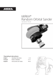
TECHNICAL MANUAL (ver.2.0)
Plasma Display:
PDP-V402/V402E
Down converter:
PDA-4003
Tilted cradle:
PDK-4001
Metal fixture for ceiling-hanging type plasma display: PDK-4002
PDK-4003
PDK-4004
PDP bracket:
PDK-4005
Metal fixture for wall-hanging type plasma display:
PDK-4006
Mobile cart:
PDK-5008
Multiple mounting fixture for plasma display:
PDM-4001
Protective filter:
PDA-4002
Speaker system:
PDP-S03-LR
This manual gives precautions, general information, and examples for installation and handling of the plasma display
and its metal fixtures.
Carefully examine the structure, material, strength, and environmental conditions for the site at which the display is to
be installed before selecting an installation method. If the site is unsatisfactory, venders should not sell or install the
equipment.
For safety
In this manual, this symbol indicates important
precautions. Read these precautions carefully.
Note:
• We are not responsible for damage caused by defective
parts supplied by third parties.
• The performance of the equipment is guaranteed only
when assembly and adjustment are performed as
described herein.
• The specifications and descriptions given in this
technical manual are subject to change without notice.
[Installation]
¶ We sell this equipment on the assumption that it
will be installed by a specialist with adequate training.
The equipment must be installed by trained vendors
or by your dealer.
¶ We are not responsible for injuries or damage
resulting from choice of unsuitable installation sites,
problems in assembly and installation, improper
installation, or natural disasters.
Contents
Features .................................................................................................................................................................. 4
specifications .......................................................................................................................................................... 6
2.1 List of specifications ..................................................................................................................................... 6
2.2 Outline drawing ............................................................................................................................................ 7
2.3 Part names ................................................................................................................................................... 8
2.4 Various pin arrangements ............................................................................................................................. 9
2.5 Remote control ........................................................................................................................................... 10
2.6 Remote control case .................................................................................................................................. 11
Installation ............................................................................................................................................................ 12
3.1 Installation environment ............................................................................................................................. 12
3.2 Installation conditions ................................................................................................................................. 14
3.2.1 Radiation .............................................................................................................................................. 14
3.2.2 Calculating calorific values ................................................................................................................... 14
3.2.3 Installation position .............................................................................................................................. 15
3.2.4 Strain on surface where equipment is installed ................................................................................... 17
3.3 Installation procedure ................................................................................................................................. 18
3.3.1 Precautions for transportation .............................................................................................................. 18
3.3.2 Unpacking ............................................................................................................................................ 18
3.3.3 Wiring ................................................................................................................................................... 20
3.4 Special installations .................................................................................................................................... 24
3.4.1 Fixing on a structure ............................................................................................................................ 24
3.4.2 Wall hanging ........................................................................................................................................ 26
3.4.3 Wall embedding ................................................................................................................................... 30
3.4.4 When the display is put in a box ......................................................................................................... 34
3.4.5 Wall hanging (vertically wall-hanging equipment) ................................................................................ 38
3.4.6 Wall embedding (vertically wall-embedding equipment) ...................................................................... 42
3.4.7 Ceiling suspension (using wires) .......................................................................................................... 46
3.4.8 Installation with the screen downward ................................................................................................ 48
3.4.9 Ceiling embedding ............................................................................................................................... 50
3.4.10 Installation on the floor ...................................................................................................................... 52
3.4.11 Installation under the floor ................................................................................................................. 54
3.4.12 Installation under the floor (using the PDM-4001) ............................................................................. 58
3.4.13 Horizontal connections ....................................................................................................................... 60
3.4.14 Vertical connections ........................................................................................................................... 61
Mounting stadard metal fixtures ........................................................................................................................ 62
4.1 Functions and features of standard metal fixtures ..................................................................................... 62
4.2 Handling standard metal fixtures ................................................................................................................ 64
4.2.1 Precautions on handling metal fixtures ................................................................................................ 64
4.2.2 Precautions for vendors performing the installation ............................................................................ 64
4.3 Stand (an accessory to PDP-V402 <PDP-V402E>) ..................................................................................... 65
4.3.1 Installing the stand ............................................................................................................................... 65
4.3.2 Outer-dimensions diagram (Unit: mm) ................................................................................................. 66
4.4 Down converter PDA-4003 ........................................................................................................................ 67
4.4.1 Specifications ....................................................................................................................................... 67
4.4.2 Outline drawing (Unit: mm) .................................................................................................................. 68
4.4.3 The outline from setting up to adjusting of down converter ................................................................ 69
4.4.4 Before using the down converter ........................................................................................................ 71
4.4.5 Mounting on the plasma display .......................................................................................................... 72
4.4.6 When mounting using only this device ................................................................................................ 75
4.4.7 Repackaging procedure ....................................................................................................................... 77
4.4.8 Operating a down converter ................................................................................................................ 78
4.5 Tilting stand: PDK-4001 .............................................................................................................................. 82
4.5.1 Specifications ....................................................................................................................................... 82
4.5.2 Outer-dimension diagram (Unit: mm) ................................................................................................... 82
4.5.3 Assembling and installing the metal fixture and mounting the plasma display ................................... 83
4.6 One-sided, ceiling-suspension metal fixture for the plasma display: PDK-4002 ........................................ 86
4.6.1 Specifications ....................................................................................................................................... 86
4.6.2 Outer-dimension diagram (Unit: mm) ................................................................................................... 87
4.6.3 Assembling and installing the metal fixture and mounting the plasma display
(same procedure as for the PDK-4003) ............................................................................................. 88
4.7 Double-sided, ceiling-suspension metal fixture for the plasma display: PDK-4003 .................................... 92
4.7.1 Specifications ....................................................................................................................................... 92
4.7.2 Outer-dimension diagram (Unit: mm) ................................................................................................... 93
4.7.3 Assembling and installing the metal fixture and mounting the plasma display ................................... 93
4.8 Ceiling-suspension metal fixture for the plasma display (head screw type): PDK-4004 ............................. 94
4.8.1 Specifications ....................................................................................................................................... 94
4.8.2 Outer-dimension diagram (Unit: mm) ................................................................................................... 94
2
Contents
4.8.3 Assembling and installing the metal fixture and mounting the plasma display ................................... 95
4.9 PDP bracket: PDK-4005 .............................................................................................................................. 98
4.9.1 Specifications ....................................................................................................................................... 98
4.9.2 Assembling and installing the metal fixture and mounting the plasma display ................................... 99
4.10 Wall hanging metal fixture for the plasma display : PDK-4006 ............................................................... 104
4.10.1 Specifications ................................................................................................................................... 104
4.10.2 Assembling and installing the metal fixture and mounting the plasma display ............................... 105
4.11 Mobile cart:PDK-5008 ............................................................................................................................ 110
4.11.1 Specification ..................................................................................................................................... 110
4.11.2 Assembling and mounting the metal fixtures, and mounting the plasma display ........................... 111
4.11.3 Mounting procedure ........................................................................................................................ 112
4.11.4 In case of mounting an optional protective filter .............................................................................. 114
4.12 Partition Multiple installation fixture ....................................................................................................... 116
4.12.1 Specification ..................................................................................................................................... 116
4.12.2 Outer dimensional drawing [Unit: mm] ............................................................................................ 117
4.12.3 Installation conditions ...................................................................................................................... 118
4.12.4 Before installation and assembly .................................................................................................... 121
4.12.5 Installation and assembly ................................................................................................................. 122
4.13 Protective filter: PDA-4002 ..................................................................................................................... 142
4.13.1 Specifications and features (Protective filter: PDA-4002) ................................................................ 142
4.13.2 Assembling and installing the metal fixture and mounting the plasma display ............................... 142
4.13.3 Mounting the PDP bracket (PDK-4005) with PDA-4002 mounted ................................................... 145
4.14 Speaker system: PDP-S03-LR ................................................................................................................ 146
4.14.1 Before operation .............................................................................................................................. 146
4.14.2 Specifications ................................................................................................................................... 146
4.14.3 Assembling and installing the metal fixture and mounting the plasma display ............................... 147
4.14.4 Precautions for mounting various metal fixtures
after the optional speakers are attached to the plasma display main body ..................................... 150
Adjustment ......................................................................................................................................................... 154
5.1 Before Beginning Adjustments ................................................................................................................ 154
5.1.1 Operating mode ................................................................................................................................. 154
5.1.2 Combination in use of remote, unit operating panel, and PC ............................................................ 155
5.1.3 List of adjustable items ...................................................................................................................... 156
5.1.4 Picture quality and white-balance adjustment memory ..................................................................... 157
5.1.5 Phase-adjustment memory ................................................................................................................ 158
5.1.6 Last memory ...................................................................................................................................... 159
5.1.7 Aging .................................................................................................................................................. 160
5.2 Menu mode .............................................................................................................................................. 162
5.2.1 Various adjustments and setting ........................................................................................................ 162
5.3 Integrator mode ........................................................................................................................................ 166
5.3.1 Adjustments and setting in the integrator mode ............................................................................... 166
5.3.2 Precautions ........................................................................................................................................ 175
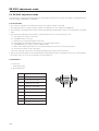
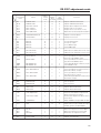
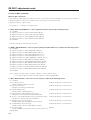
5.4 RS-232C adjustment mode ..................................................................................................................... 176
5.4.1 Precaution .......................................................................................................................................... 176
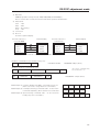
5.4.2 Interface ............................................................................................................................................. 176
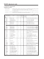
5.4.3 RS-232C commands table ................................................................................................................. 178
5.4.4 List of GET commands ...................................................................................................................... 180
5.5 KEY LOCK/UNLOCK ................................................................................................................................. 182
5.5.1 Functions ........................................................................................................................................... 182
5.5.2 Setting method .................................................................................................................................. 182
6.1 Pseudo contour ........................................................................................................................................ 183
6.2 Precautions ............................................................................................................................................... 184
Warning
• To prevent damage or injury, carefully read and follow this manual and all labels provided on the main display
body before undertaking assembly, installation, movement, or adjustment.
• To prevent fire and electric shock resulting from moisture infiltration, never use this system outdoors.
• To prevent injury, take care when handling the system's sharp edges.
• When installing the system at a height, create an off-limits zone to prevent injury or secondary damage in case of
falling equipment.
• To prevent fire and electric shock, never place foreign objects within or make modifications to the equipment.
• Always observe the following operating environmental conditions:
Temperature : 0 °C to 40 °C
Humidity
: Relative humidity 20% to 80%
• Make sure the site is well-ventilated, and take care to maintain adequate ventilation following installation.
3
Features
Features and functions of the plasma display (PDP-V402/V402E)
¶ Layout Freedom and Slim Design
Layout freedom is enhanced by providing the highest level of thinness and lightness in the industry (Thinness: 88
mm, Weight: 30.8 kg).
The thin, light form of the plasma display panel provides immediate improvement of operating conditions by increasing
the potential installation locations and style coordination for smooth integration into a variety of applications.
¶ Materialization of higher luminance and picture quality
Improved efficiency of the driving current provides even higher luminance.
Adoption of a black stripe and improved filters provides better daylight contrast and color fidelity.
¶ Flexible Response to a Wide Band of Input Signals
VIDEO signals and 640 x 480 dot (VGA) PC signals are displayed with great clarity.
Connection of the exclusive high performance down converter (Scheduled for release soon) enables broad response
up to 1024 x 768 dot (XGA) PC signals, and provides the optimum solution for sharp resolution to prevent loss of
information such as fine characters and lines.
¶ Best display for industrial and public purposes
Our plasma display (PDP-V402/V402E) is specifically designed for use as an industrial display. It has been designed
to provide the following features:
• An aspect ratio of 4:3 optimal for use as a public display
• A versatile mounting structure and metal fixtures permitting wall or vertical installation
• Equipped with integrator mode that enables fine adjustment of white-balance
• Provided with RS-232C as an external control interface
• Color temperature (white-balance) changeover function to allow retakes
• Equipped with a full set of input/output terminals (four input systems and one output system) capable of
handling a wide range of applications
• Operating state monitoring function
• Priority input auto switching mode
• Key lock function to prevent tampering
• OSD (On Screen Display) ON/OFF function
Our plasma display has been designed for durability and reliability, features required in industrial displays. Its features
and quality allow use in a wide range of applications and locations.
4
Features
5
List of specifications
2.1 List of specifications
Light emission panel ...... 40-inch plasma display panel
Aspect ratio ............................................................. 4:3
No. of pixels ................... 640 × 480 (adaptable to VGA)
Pixel pitch
........... 1.26 (horizontal, RGB trio) × 1.26 (vertical) mm
No. of gradations ................................ 256 gradations/
16,770,000-color full color
View angle ............................ Horizontal : 160° or more
Vertical : 160° or more
Input/output terminals
RGB Input
1 BNC Terminal R, G, B (fixed to 75 Ω input)
Analog R, G, B (fixed 75 Ω input, G-on Sync input)
HD (H/V SYNC), VD (switching between 75 Ω /2.2 kΩ
input)
Switch VD according to the sync output impedance
of the connector. Switch VD to 2.2 kΩ except when
the sync output impedance is 75 Ω. (The terminal is
factory-set to 75 Ω.)
2 Mini Dsub 15P
Analog RGB, 0.7 Vp-p, 75 Ω input, G-on Sync input
(Sync 0 - 3 Vp-p)
Synchronization:
HD, VD 2.2 kΩ input, 2.0 - 5.0 Vp-p (Positive/Negative),
G-on Sync switch (G-on Sync ON/OFF Change over)
Turn the switch on only if images become greenish
(when the G-on Sync signal is applied) at RGB2 input.
Under normal circumstances, the switch is left off.
(The switch is factory-set to G-on Sync OFF.)
Video input ...... Single-system BNC terminal 75 Ω input
Composite 1 Vp-p
Y/C input .......... Double-system BNC terminal 75 Ω input
Control input .... Dsub 9P (RS-232C control)
Video output .... Single-system BNC terminal 75 Ω output
(Note: Up to four units, including the unit
to which the signal is first input, may be
connected when the equipment is
connected in series using this output
terminal. However, increasing the
number of connected units may increase
the noise.)
Applicable sources
1 Video system: NTSC <PAL/NTSC Dual>
2 Computer system
1.Resolution
AT-compatible: VGA (640 dots × 480 lines)
Macintosh:
13-inch mode (640 dots × 480 line)
PC-9800:
Normal mode (640 dots × 400 line)
6
2. Synchronizing frequency:
AT-compatible: 31.5 kHz (horizontal), 59.9 Hz (vertical)
37.9 kHz (horizontal), 72.8 Hz (vertical)
37.5 kHz (horizontal), 75 Hz (vertical)
Macintosh:
35 kHz (horizontal), 66.7 Hz (vertical)
PC-9800:
24.8 kHz (horizontal), 56.4 Hz (vertical)
31.5 kHz (horizontal), 70.1 Hz (vertical)
Does not accommodate the interlaced mode of the computer.
Some types of computer have multiple indication modes.
However, some modes cannot be displayed even if the computer
meets the specifications. Please contact your dealer for further
information.
Power source ...................... 100 to 120 V AC, 50/60 Hz
<220 to 240 V AC , 50/60 Hz>
Inrush ................................ 70 A or less <30 A or less>
Power factor ............................................ 0.95 or more
Power consumption .............. 350 W (in standby: 2 W)
Outer dimensions ........ 916 (W) × 714 (H) × 88 (D) mm
Weight .............................................. 30.8 kg <31.6 kg>
Operating environment temperature range
..................................................................... 0 to 40 °C
Operating environment humidity range
.................................... Relative humidity 20% to 80%
Operating environment air pressure range
.................................... 0.8 - 1.1 atmospheric pressure
Storage conditions (plasma display panel alone)
Storage ambient temperature range
-20 to 60°C (Temperature gradient (10°C/hr. or less)
Storage ambient humidity range
.......................... 20 to 90% (without condensation)
Storage ambient air pressure range
............................... 0.6 - 1.5 atmospheric pressure
Storage conditions (Package state)
Storage environment temperature range
............................................................ –40 to 60 °C
Storage environment humidity range
............................... Relative humidity 20% to 90%
Storage ambient air pressure range
............................... 0.6 - 1.5 atmospheric pressure
Storage stack limit ............................ maximum of 10
Accessory
Power cord (PDP-V402 only) ........................................ 1
Remote control ............................................................ 1
Remote control case .................................................... 1
AA battery .................................................................... 2
Stand ............................................................................ 2
Bolt ............................................................................... 2
Washer ......................................................................... 2
Cable clamp .................................................................. 3
Operating Instructions .................................................. 1
Warranty card ............................................................... 1
• Specifications and appearance are subject to change
without notice.
• < > shows the PDP-V402E.
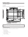
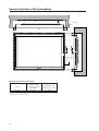
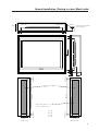
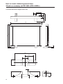
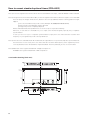
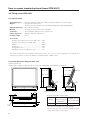
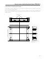
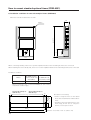
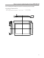
Outline drawing
2.2 Outline drawing
Plasma display main body weight : 30.8 kg <31.6 kg>
Material : Front - Plastic, Back - plate
Treatment : Front - Leather satin gray paint, Back - Semi-matte black paint (Coating colors should be according to
Pioneer's original color specification)
Packing specifications - See “3.3.2 Unpacking”
• < > shows the PDP-V402E.
604.8 (Effective picture size)
: Location of center of gravity
24
<Light-accepting section
of the remote controller>
806.4 (Effective picture size)
<Operation panel
of the main body>
202.5
107
φ12 (the opening for infrared remote control signals)
24
14
14.8
14-M8 (with φ16-hole rivet)
Rear View
7
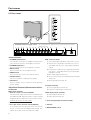
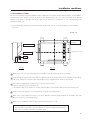
Part names
2.3 Part names
STANDBY
/ON
1
2
INPUT
3
MENU
4
ADJUST
5
SET
6
<Terminals and power supply section>
(The terminals and power supply section are located at the back of the plasma
display main body.)
7
OFF
8
ON
REMOTE
9 0
OFF
RGB-2
ON 75 (Ω) 2.2k
G ON SYNC
SYNC
-
VD
=
~
!
@
#
HD
B
G
R
C
(H/V SYNC) RGB-1 (ON SYNC)
Y/C
$
%
^
Y
OUT
VIDEO
IN
&
*
(
RS-232C
<Control Panel>
1 STANDBY/ON indicator
The indicator is red when in standby mode and turns
RGB-1 input terminals
0 Sync Signal Input Impedance switch (75 Ω/2,2 kΩ)
green when the power to the display is turned on.
2 STANDBY/ON button
- Vertical Sync Signal Input terminal: (75 Ω/2,2 kΩ,
switchable with the Sync Signal Input Impedance
Press to turn the power to the display on and off.
3 INPUT button
switch)
= Horizontal or Composite Sync Signal Input terminal:
Press to switch the various input functions.
4 MENU button
(75 Ω/2,2 kΩ, switchable with the Sync Signal Input
Impedance switch)
Press to enter the menu screen and exit from it.
5 ADJUST button
~ Blue Signal Input terminal: 75 Ω
! Green or Green with Sync Signal Input terminal (ON
Use the +/– buttons to adjust picture quality.
6 SET button
SYNC) :75 Ω
@ Red Signal Input terminal: 75 Ω
Press to finalize menu selections when adjusting
picture quality.
<Rear Panel Terminals/Connections to Power Source>
RGB-2 input terminals
7 Remote control out switch (ON/OFF)
This switch will output remote control commands from
the RGB-2 (D-SUB 15-pin) terminal to control external
peripheral devices planned for future sales release.
Normally be sure to use set to OFF.
8 MINI D-SUB 15-pin terminal
9 G on Sync mode selection switch (ON/OFF)
If the images become greenish when an external
device is connected to the RGB-2 input terminal, turn
ON the G on SYNC mode. Normally set to OFF.
8
Y/C input terminals
# Color Signal Input terminal: 75 Ω
$ Luminance Signal Input terminal: 75 Ω
VIDEO input/output terminals
% Video Output terminal: 75 Ω
^ Video Input terminal: 75 Ω
& Control Signal Input terminal (RS-232C)
* AC inlet
( MAIN POWER switch
Part names
2.4 Various pin arrangements
RGB-2 input terminal (mini D-sub 15-pin
connector: female)
Pin arrangement
5
1
10
1
5
6
15
Pin No.
RS-232C terminal (D-sub 9-pin connector: male)
Pin arrangement
11
Signal
6
Pin No.
9
Signal
1
2
R
G
1
2
NC (not connected)
TxD (Transmit Data)
3
4
B
NC (not connected)
3
4
RxD (Receive Data)
NC (not connected)
5
6
GND
GND
5
6
GND
NC (not connected)
7
8
GND
GND
7
8
NC (not connected)
RTS (Reguest To Send)
9
10
NC (not connected)
GND
9
NC (not connected)
11
12
NC (not connected)
Remote control signal output (Note)
13
14
HD or H/V SYNC
VD
15
NC (not connected)
Note: This is a pin for controlling an external add-on
peripheral device to be released in the near future.
1 This can be turned ON/OFF with the remote out
switch 7.
When ''OFF'' is selected, it is NC (not connected).
9
Remote control
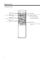
2.5 Remote control
Power button
Turns power on or off.
VIDEO button
Sets Input Function to VIDEO
Input.
MENU button
Used to switch the menu
screen and normal screen.
ADJUST button
Used to adjust images.
STANDBY/ON
VIDEO
Y/C
INPUT
SELECT
RGB 1
RGB 2
MENU
RGB 1 and 2 buttons
These buttons set Input
Functions to RGB 1 (BNC
terminal) and RGB 2 (Mini DSUB terminal), respectively.
SET
Î
10
Y/C button
Sets Input Function to Y/C input.
SET button
This button used to select an
adjustment item for picture
adjustment.
Remote control
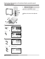
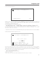
2.6 Remote control case
Remove the peel-off paper from the double-sided tape on the back of the remote control case, and attach it on the
back of this display or on the installation metal fixture to use as a remote control storage case.
Remote
Example of attaching a
remote control case
Remote control case
Double-sided tape
(Note) Make sure not to block any air inlet hole with the remote control case.
11
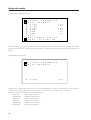
Installation environment
3.1 Installation environment
The plasma display and special metal fixture must be installed after careful discussion with the building owner and
manager of the building. Never undertake installation without careful consideration of the consequences. In addition,
contact the contractor responsible for building construction and interior structure design and confirm the structure and
safety of the building.
: Safety precautions
1) Structure of installation site
Be sure to use an appropriate installation method, after fully understanding the structure of the installation site.
There are many types of building structures and materials, and appropriate installation methods will vary accordingly.
When using a special metal mounting fixture, consult your dealer or the maker of the fixture.
Before drilling holes, always consider the location of wiring and piping within the building.
2) Load resistance of the installation site
Select an installation site capable of supporting the combined weight of the metal fixture and display.
“Sufficient strength to withstand” means sufficient strength to withstand a weight four times that of the
main body including the metal fixture.
3) Horizontal plane
Select a level, sturdy, installation site with sufficient load-bearing capacity.
When using suspension bolts, take care to distribute load evenly on the ceiling on the floor of the installation site.
4) Securing installation space
Select an installation site with adequate space for working. This work requires two or more people.
Remember to leave adequate space for future maintenance.
5) Peripheral equipment
Installation sites close to air conditioner outlets or light bulbs may be unsuitable due to potential damage from
dust, temperature, humidity, or condensation.
6) Dangerous location sites
Do not install the display at locations where it may be leaned against or grasped. Similarly, avoid installing at sites
subject to excessive vibration or physical shock.
7) Lighting
• For more visible display, avoid installation in very bright locations. Before choosing the location site and
method,carefully consider the location of lighting fixtures and direction and strength of sunlight.
• In bright locations, images may appear dark even if the luminance is increased. Adjusting picture brightness to
excessively high levels to compensate for extremely bright ambient lighting may reduce the service life of the
display panel.
8) Semi-outdoor installation
This machine is designed for indoor use. Installed semi-outdoors, the display will be subject to problems resulting
involving the following factors:
• Water, dust, etc.
• Changing temperature and humidity
• Air-borne salt
To ensure that pictures appear normal, avoid installation in locations subject to direct sunlight.
12
Installation environment
9) Temperature and humidity
The installation site should conform to the following temperature and humidity conditions:
• Operating temperature range: 0 to 40 °C (Depending somewhat on installation conditions, see descriptions of
special installations and methods for installation of the standard metal fixture.)
Operating environment humidity range .............. Relative humidity 20% to 80%
Operating environment air pressure range ......... 0.8 - 1.1 atmospheric pressure
Storage conditions (plasma display panel alone)
Storage ambient temperature range ...................... -20 to 60°C (Temperature gradient (10°C/hr. or less)
Storage ambient humidity range ............................ 20 to 90% (without condensation)
Storage ambient air pressure range ....................... 0.6 - 1.5 atmospheric pressure
Storage conditions (Package state)
Storage environment temperature range ............... –40 to 60 °C
Storage environment humidity range ..................... Relative humidity 20% to 90%
Storage ambient air pressure range ....................... 0.6 - 1.5 atmospheric pressure
We recommend against installing electronic equipment, including this display, in high-humidity environments. If
the display must be installed at a site subject to humid conditions, observe the following:
• Never install the machine in environments having humidity falling outside the specification range.
• Ground the equipment.
• Do not allow condensation to form on any display surface.
• Do not allow water or other liquids to enter the unit.
10) Condensation
One common problem encountered during winter is condensation, drops of water that form on display surfaces
when the ambient temperature rises suddenly. Such moisture may adversely affect the performance of the display.
If condensation is observed, turn off the machine for one hour before attempting to use it again. Another solution
is to raise the ambient temperature gradually, if possible.
11) Power requirements
The voltage range required to ensure specified performance is ± 10% of the rated voltage. Keep in mind that highimpedance power distributing wires will produce an effect equivalent to a voltage drop. Watch for the following
cases, and recheck power distribution.
• The voltage drop between the switchboard and the plasma display is significant.
• When the power to the machine is turned on and off, voltage fluctuations are large.
Estimate the power consumption of this machine as 400 VA plus a safety margin.
The inrush current when the machine is turned on is approximately 70 A <30 A>.
< > shows the PDP-V402E.
12) Coverage of the remote control
The display communicates with the remote control through weak infrared signals, which typically reflect off display
surroundings. The operating range of the remote is affected by the reflective characteristics of surrounding objects.
If the range of coverage appears to be unusually short, check the following:
• Do the walls and platform for the display have a mirror or white finish?
• Are there objects near the infrared-accepting section?
• Are the remote control batteries weak or dead?
Other devices using infrared remote control and wireless systems may not work properly if located close to the
infrared-emission source of the display. Consult your dealer before using such equipment near the display.
13
Installation conditions
3.2 Installation conditions
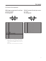
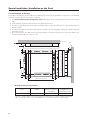
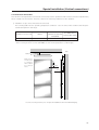
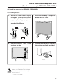
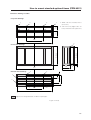
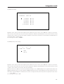
3.2.1 Radiation
This display comes with multiple ventilation holes for efficient radiation of heat. Avoid blocking any of these holes.
Ventilation holes are indicated by arrows in the following drawing.
2
ø6
49.8 mm
539 mm (Size of air inlet hole)
463 mm (Size of air inlet hole)
377 mm (Size of air inlet hole)
49 mm (Size of air inlet hole)
328 (Size of air inlet hole)
638 (Size of air inlet hole)
49.8mm
23 mm
110mm
50mm 40mm
Exhaust fan 5 units
380 (Size of air inlet hole)
150mm
494 mm (Size of air inlet hole)
90mm
58 mm
23mm
C.L.
48.8mm
23mm
46mm 152mm (Size of air inlet hole)
82.5mm 101.5mm
4mm
152mm (Size of air inlet hole)
160mm (Size of air inlet hole)
284.3 mm
189.5mm (Size of air inlet hole)
858mm (Size of air inlet hole)
402.4mm
916mm
Air flows out through five of the ventilation holes and flows in through the other holes. For special installations, such
as wall-hanging or embedding, additional restrictions apply concerning operating temperature. See “3.4 Special
installations”.
3.2.2 Calculating calorific values
Estimate the maximum power consumption per device as 400 W plus a safety margin. Most of the power consumed
is converted to heat, so power consumption is roughly equivalent to generated heat.
1) Conversion to calories
[W] × 0.86 = [kcal/h]
Calorific value per display
400 × 0.86 = 344 [kcal/h]
2) Conversion to British thermal unit (BTU)
[W] × 3.41 = [B.t.u./h]
Calorific value per display
400 × 3.41 = 1256 [B.t.u./h]
14
Installation conditions
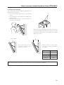
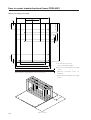
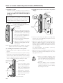
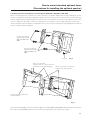
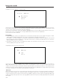
3.2.3 Installation position
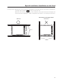
We recommend using the metal installation fixture made by Pioneer. When using a different fixture, use the M8 bolt
hole provided on this display to mount the fixture to the display. Remove the hole rivets on the back of the plasma
display, if necessary for the particular fixture. Tighten bolts with a force of 60 kg.cm or less. Overtightening may
damage the blind nuts.
• The following figure indicates mounting holes that can be used. (Use a coin or similar object to turn the cap to
remove it.)
'a' hole × 14
Hole a
Hole a
Exhaust holes
(with fans)
Mounting surface
Metal fixture
Hole a
Centerline of 'a' hole
Hole a
Bolt
13 to 20 mm
Hole a
Side view
Hole a
Rear view
Make sure to use 4 or more holes that are horizontally or vertically symmetrical to the centerline.
Use bolts that do not penetrate more than 13 to 20 mm from the mounting surface of the machine (see the above
side view). If the bolts used are longer than the above, they may damage the inside of the machine.
Do not block ventilating holes or blowholes in the rear of the machine.
Hot air is emitted from the ventilating holes.
Care must be taken not to weaken or soil the wall at the back of the machine with the hot air from the holes.
Glass is used in this machine. It must always be mounted on the straight face.
Make sure to finger tighten the bolts 2 or 3 times, and after confirming that the bolts are inserted in the right
direction, use the tool for final tightening.
Make sure to use M8 (p=1.25) bolts (Any other bolts should not be used).
For mounting metal fixtures and so forth, use our genuine parts as much as possible.
We will not be responsible in any way whatsoever for any accidents and/or damages
due to the use of parts other than our genuine parts.
15
Installation conditions
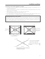
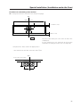
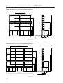
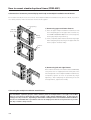
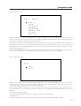
We recommend mounting at a minimum of 4 points, and at 6 or 8 points as shown below if possible. Avoid mounting
the display with the particular 4-point scheme shown below.
Mounting method — bad example
Mounting method — good example
A. 8-point mounting
B. 6-point mounting
(Do not block ventilation holes.)
C. 4-point mounting (Metal fixture is mounted vertically.)
(Do not block ventilation holes.)
D. 4-point mounting (Metal fixture is mounted horizontally.)
(Take care to avoid pinching power cord, signal cable, etc.)
16
(Do not block the fan.)
Installation conditions
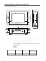
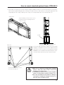
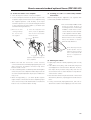
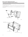
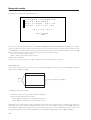
3.2.4 Strain on surface where equipment is installed
1 This display uses glass in its display section. When using a third-party metal fixture, check that strain is 1 mm or
less by the following method.
2 Tightly fit a thread using a force of φ 0.1psi or less diagonally through the mounting bolt openings on the mounting
surface, as shown in the drawing.
3 Measure distance L of the intersection of the strings in the center section.
The relationship between strain and L is given by Strain = L × 2.
4 If L is 0, interchange the front and rear positions of two strings and check the distance again. If the value of L is not
0, it is the true value of L. If L is 0 after the position is changed, strain is approximately 0.
* Regarding the distortion of 1 mm or below:
It is possible that the housing of this device causes a maximum distortion of about 3 mm. It is also possible that
this device causes stress on the glass when this device suffers a distortion of 4 mm or more. Therefore, make
sure to keep the distortion on the mounting surface within 1 mm so that the total distortion should remain less
than 4 mm including the distortion of the housing itself under it.
a
d
d
a
A
A
Plasma displaymounting surface (mounting
metal fixture)
Holes for
mounting
bolts
c
b
c
b
Plasma display-mounting surface
(mounting metal fixture)
a
d
Thread
Point e is the center of the thread a-b.
Point f is the center of the thread c-d.
Distance between e and f = L
Points e and f are indicated in an enlarged figure for more detailed understanding.
f
e
Thread c
Right angle
b
Enlarged drawing of the intersectional part A
(showing the part obliquely)
17
Installation procedure
3.3 Installation procedure
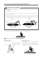
3.3.1 Precautions for transportation
1 Use two workers to move packages. Do not grasp the PP band during transportation. The band may snap and
result in injury.
2 For transportation and storage, keep the package horizontal. Do not stack packages longitudinally or laterally. If
packages are transported or stored while longitudinally stacked or laterally stacked, the company is guarantee will
be invalidated.
3 For transportation and storage, never stack more than ten packages, as indicated on the upper carton.
4 For transportation and storage, observe the conditions detailed on the upper carton.
5 To protect the glass surface of the display, avoid stepping on the package, placing heavy items on top, or sticking
sharp objects into the top.
*
If the plasma display and fixture needs to be packed and transported again, follow the packing method and
precautions given below:
• Pack goods by reversing the procedure for unpacking given in “3.3.2 Unpacking”. Take care when replacing the
mirror mat to place the smooth face facing out, with the soft surface toward the product.
• Replace the remote control and the stand in the specified positions. If they are placed in the center of the upper
pad, the panel may be damaged during transportation.
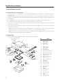
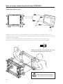
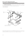
3.3.2 Unpacking
1) Packing specifications: 1130 (W) × 295 (H) × 852 (D) 39.5 kg <40.4 kg>
< > shows the PDP-V402E.
No.
PDP-V402 Only
27
1.
2.
3.
4.
5.
6
9
27
18
19
PDP-V402 Only20
15
26
28
4
23
25
16
22
17
5
PDP-V402 Only
1
21
PDP-V402 Only
2
3
2
1
7
6.
7.
8.
9.
10.
Upper Carton
Under Carton
Mirror Mat
Literature Bag
Operating Instructions
11.
12.
13.
14.
15.
Plasma Caution Sheet
Plasma Caution Sheet
Caution Sheet
Remote Control Unit
Battery Cover
16.
17.
18.
19.
20.
Batteries (R6P, AA)
Vinyl Bag
Cable Clamp
Display Stand V
Controller Case
21.
22.
23.
24.
25.
AC Power Cord
Bolt (Hex)
Washer
Warranty Card
Vinyl Pouch
26.
27.
28.
29.
Vinyl envelope
Label
Caution Sheet
Warranty Card
18
26
29
8
18
Upper Pad A
Upper Pad B
Upper pad C
Upper Pad
Partition Box
14
10
11
13
12
24
Name
Installation procedure
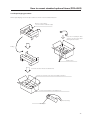
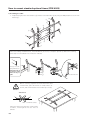
2) Procedure for unpacking
1 Remove the PP band.
2 Slowly lift and remove the upper carton.
3 Remove the catalogue bag (9) (instruction manuals), stand (19), and the plastic bag for (26) (accessories) on
top of the upper pad.
Caution: If the upper pad (4) is removed before removing these items, the items may fall and damage the
product.
4 Remove the upper pad (4).
5 Open the mirror mat (8).
6 Remove the product. (Requires two workers to remove the set.)
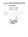
3) Movement after unpacking
Moving the product after unpacking requires two workers.
• Never drag the product on the floor.
• The display screen (front protective panel) is fragile. Move it slowly, and take care to avoid striking it or scraping
objects against it.
• Remove the protective film applied to the front protective panel only after construction and work are finished
and dust has settled.
19
Installation procedure
3.3.3 Wiring
1) Power source connection
• Refer to Power cord connection on page 24 <36, 82> of the instruction manual.
• For power source capacity, see the description given in “3.1 Installation environment, 11) Power requirements”
in this manual.
2) Signal cable connection
(1) Connecting to a PC
• See the description given in Connecting to a PC
, on pp. 19 to 20 <26 to 29, 72 to 75> of the instruction
manual.
(2) Connecting to a video cassette recorder
• See the description given in Connection to a video cassette recorder
81> of the instruction manual.
, on pp. 21 to 23 <30 to 35, 76 to
(3) Precautions
• Use coaxial cables. For video signals, use the 3C-2V for lengths of 15 m or less, and the 5C-2V for lengths of
30 m or less. Since data signals are more easily degraded than video signals, use a thick cable (e.g. a 5C-2V
cable) for data communications, even for lengths of 15 m or less. Try to minimize the distance between the
signal transmission device and the plasma display unit.
• If a video cable is wired close to a dimmer, neon tube, air conditioner, or other device, or if it is wired in
<
parallel to a cable television cable, display performance may be affected.
> shows the PDP-V402E.
3) Treatment of wires
• For long-term or permanent installations, rather than short-term installations for specific events, use wires of
the proper length, carefully considering the placement of all other wires.
• Place wires so that no load or force is applied to the connecting terminals. For short-term use, wires may be
bundled with string. For long-term installations, form wire bunches using cable clamps.
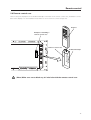
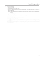
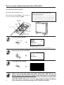
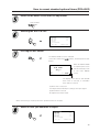
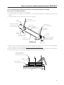
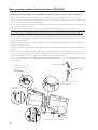
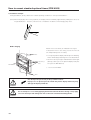
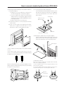
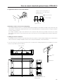
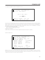
4) Mounting cable clamp
Use a cable clamp to form cable bunches in the upward direction, as shown in the drawing.
Cable clamps are supplied for bundling connection cables.
Follow these steps when using cable clamps:
<Back>
Peel off the paper at the back and insert the supplied
cable clamp into the mounting holes until it clicks.
Peel off the label covering the mounting holes before attaching the cable clamps.
Caution
20
When cables are inserted in a cable clamp, keep the clamp at least 10 cm from the wall to allow
ventilation.
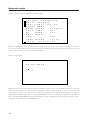
Installation procedure
21
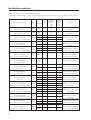
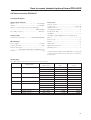
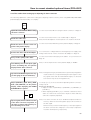
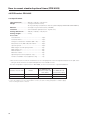
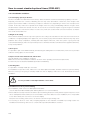
Installation conditions
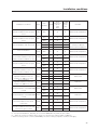
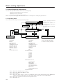
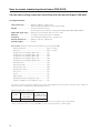
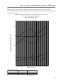
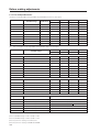
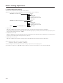
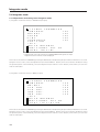
Outline of conditions for installing PDP-V402 system
For installation space (distances from surrounding structures and so forth), make sure to carefully read this section.
Installation conditions
Room
VIDEO
Page
temperatures
PC-9800
70.1Hz
72.8Hz
75Hz
Remarks
Normal installation
Rear open air *2
P24
40°C
O
O
O
Vertical installation
Rear open air *2
P24
40°C
O
O
O
30°C
O
O
×
35°C
O
O
×
40°C
×
×
×
35°C
O
O
O
Excluding the rear side
Open air *2 without fan
40°C
O
O
O
30°C
O
O
×
and partition
Upper and lower clearances 0, left
35°C
×
×
×
40°C
×
×
×
and right clearances 100 mm
without fan and fan and partition
40°C
O
O
O
Upper and lower clearances 0, left
and right clearances 100 mm
Wall hanging
Normal installation
P26
Rear clearance between 0 and 50 mm
Wall hanging
Normal installation
Rear clearance of 50 mm or more
Wall hanging (recessed space)
Normal installation
P26
P28
Rear clearance between 0 and 50 mm
Wall hanging (recessed space)
Normal installation
Rear clearance of 50 mm or more
Wall embedding (less than150 mm)
Normal installation
P28
Normal installation
Front mesh
Box installation
Normal installation
P30
Wall hanging
Vertical installation
Wall hanging
Vertical installation
P36
P38
P38
Wall hanging (recessed or raised space)
Vertical installation
Rear clearance of 100 mm or more
Open air *2 without fan
and partition
O
O
Without fan and partition
35°C
O
O
O
Upper, lower, left and right
40°C
O
O
×
rear clearances 100 mm
without fan and partition
35°C
O
O
O
40°C
×
×
×
Upper, lower, left and right
rear clearances 50 mm
30°C
O
O
O
35°C
O
O
×
40°C
30°C
×
O
×
O
×
×
35°C
×
×
×
Excluding the rear side
Open air *2 without fan
40°C
30°C
×
O
×
O
×
O
and partition
Excluding the rear side
35°C
O
O
×
40°C
O
O
×
Open air *2 without fan
and partition
35°C
O
O
O
40°C
O
O
×
30°C
O
O
O
35°C
O
O
×
40°C
×
×
×
35°C
O
O
O
Upper, lower, left and right
rear clearances 100 mm
40°C
O
O
×
without fan and partition
P38
Rear clearance of 100 mm or more
Wall hanging (recessed or raised space)
Vertical installation
Rear clearance between 50 and 100 mm
and partition
Excluding the rear side
O
P34
Rear clearance between 0 and 50 mm
Wall hanging
Vertical installation
Rear clearance between 50 and 100 mm
and partition
Open air *2 without fan
40°C
P32
Rear mesh
Box installation
Normal installation
Side mesh
Open air *2 without fan
without fan and fan and partition
Rear open air*2
Wall embedding (recessed space)
22
PC-9800
56.4Hz
Machintosh
66.7Hz
VGA
60Hz
P40
P40
without fan and partition
Upper, lower, left and right
rear clearances 50 mm
without fan and partition
Excluding the rear side
Open air *2 without fan
and partition
Upper, lower, left and right
rear clearances 100 mm
without fan and partition
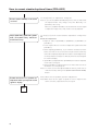
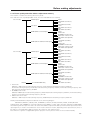
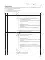
Installation conditions
Installation conditions
Wall embedding (less than 60 mm)
Vertical installation with rear open
Room
VIDEO
Page
temperatures
P42
air *2
Wall embedding (less than 150 mm)
Vertical installation with rear open
air *2
Wall embedding
Vertical installation with front mesh
PC-9800
56.4Hz
Machintosh
66.7Hz
VGA
60Hz
PC-9800
70.1Hz
72.8Hz
75Hz
Remarks
Without fan and partition
40ºC
O
O
O
35ºC
O
O
O
40ºC
O
O
×
30ºC
O
O
O
35ºC
O
O
×
Upper, lower, left and right
clearances 100 mm
40ºC
×
×
×
without fan and partition
40ºC
O
O
O
Without fan and partition
35ºC
O
O
O
40ºC
×
×
×
35ºC
O
O
O
40ºC
O
O
×
35ºC
O
O
O
40ºC
O
O
×
30ºC
O
O
×
35ºC
×
×
×
40ºC
×
×
×
35ºC
O
O
O
40ºC
×
×
×
30ºC
O
O
×
40ºC
×
×
×
35ºC
O
O
×
40ºC
×
×
×
35ºC
O
O
O
40ºC
×
×
×
35ºC
O
O
O
40ºC
×
×
×
Without fan and partition
P42
P44
Ceiling suspension (using wires)
Vertical installation
P46
Ceiling installation
Downward installation with rear
P48
clearance between 50 mm or more
Ceiling embedding (using wires)
Vertical installation with rear open
air *2
Floor installation
Upward installation with rear
P50
Upward installation with rear
clearance of 300 mm or more
Floor installation
Upward installation with rear
P54
Upward installation when PDM-4001 P58
is used
Floor installation
Upward installation when PDM-4001 P58
is used
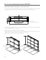
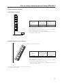
Wall hanging installation
Normal installation with lateral
connection
Wall hanging installation
Normal installation with horizontal
connections (up to 3 units)
Without fan
With fans
P54
clearance of 300 mm or more
Floor installation
Without fan and partition
Without fan and partition
P52
clearance between 50 mm or more
Floor installation
Without fan and partition
Without fan
With fans
Without fan and partition
P60
Without fan and partition
P61
*1 : For special installations, basically, do not use PC-9800 (70.1 Hz), VGA (72.8 Hz, 75Hz)
*2 : ''Open air'' means a condition where there is no interference within a radius of 300 mm.
* When mounting a down converter (PDA-4003), the same working temperate conditions will apply.
23
Special installations (Fixing on a structure)
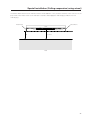
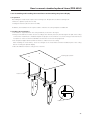
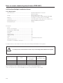
3.4 Special installations
This display may be installed in several different positions, including wall-hanging and wall-embedding. Conditions,
including temperature, may restrict the use of certain positions or installation methods.
Consider installation methods and conditions, and see the description given in “3.1 to 3.3” in this chapter.
All the measurement conditions in this manual are set in conformity with the following:
• 100% white light is applied.
• After sufficient aging
All measurements should be performed under the same conditions. The aging time needed for measurement
depends on the size of the installation space, but the standard time is approximately 2.5 hours.
“Sufficient strength to withstand” means sufficient strength to withstand a weight four times that of the main body
including the metal fixture.
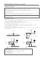
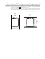
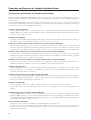
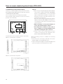
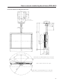
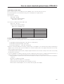
3.4.1 Fixing on a structure
1mm MAX.
To fix the machine on a structure, observe the following conditions:
1 When fixing on a structure, make sure to install the display in a complete open-air condition (a condition that has no
interference within a radius of 300 mm of this display).
2 After fixing on a structure, the distortion of the unit must be within 1 mm.
3 Do not block holes other than those shown blocked in the fixing figure on the next page.
4 Use a structure 20 mm or less in thickness.
(In the case of the fixing examples 1 and 4 on the next page, the thickness of the structure is not limited.)
5 If an L-shaped structure is used, the thickness of the structure must be 100 mm or less.
6 Use a structure with sufficient strength.
7 Care must be taken not to apply stress to the power cable.
* The descriptions in 2 - 7 indicate the common precautions for fixing the machine on the structure in “wall-hanging”
and “wall-embedding.”
100 mm
or less
L-shaped structure
Distortion of the unit is 1mm max.
20 mm or less
in thickness
20 mm or less
in thickness
36 mm or less in width
The thickness of the examples 1 and
4 on the next page is not limited.
36 mm or less in width
The thickness of the examples 1 and
4 on the next page is not limited.
Operating temperature requirements
When normally installed
• Ambient temperature requirement: 0 to 40°C (Examples 1 and 2)
When vertically installed
• Ambient temperature requirement: 0 to 40°C (Examples 3 and 4)
When installing speakers
For ambient temperature requirements, the same requirements as indicated above apply.
* When mounting the down converter (PDA-4003), the same working temperature conditions apply.
24
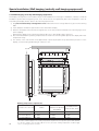
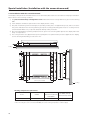
Special installations (Fixing on a structure)
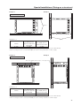
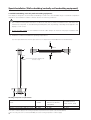
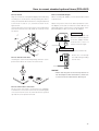
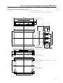
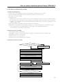
Example 1:
Example 2:
When normally installed
Beams
Example 1, 2
Beams
VIDEO
PC-9800 (56.4Hz)
Machintosh(66.7Hz)
0~40°C
VGA (60Hz)
0~40°C
PC-9800 (70.1Hz)
VGA (72.8Hz, 75Hz)
0~40°C
* The same conditions apply to the working temperature requirements for a speaker system (PDP-S03-LR).
*When mounting the down converter (PDA-4003), the same working temperature conditions apply.
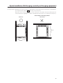
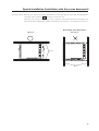
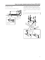
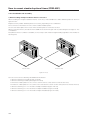
Example 3:
Example 4:
When vertically installed
Mount the display with the fans on the upper side.
Example 3, 4
VIDEO
PC-9800 (56.4Hz)
Machintosh (66.7Hz)
0~40°C
VGA (60Hz)
0~40°C
PC-9800 (70.1Hz)
VGA (72.8Hz, 75Hz)
0~40°C
* The same conditions apply to the working temperature requirements for a speaker system (PDP-S03-LR).
* When mounting the down converter (PDA-4003), the same working temperature conditions apply.
25
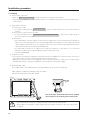
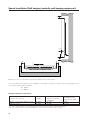
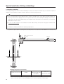
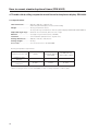
Special installations (Wall hanging)
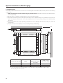
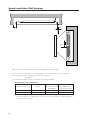
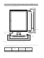
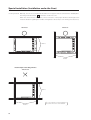
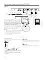
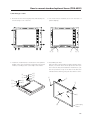
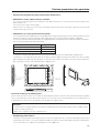
3.4.2 Wall hanging
This display may be wall-mounted. Since this form of mounting affects ventilation patterns inside, observe the following
requirements:
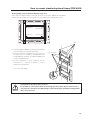
1 When mounting plate metal, avoid blocking any ventilation holes. Use plate metal of the size indicated in the
following drawing.
2 Provide space for adequate ventilation between the wall and the display.
3 Use plate metal having sufficient strength (with a safety factor of approximately four), and attach at four points (4point mounting) as shown below. Since wall installations involve certain hazards, always follow double-safety
procedures.
4 The following table lists proper operating temperatures. Use the display within the listed range of outside air
temperature.
5 Keep deformation of the display to 1 mm, including twisting and bending.
Wall
Do not block this area at either the top or bottom.
50mm
Do not block this area at either the left or right.
40mm
A
40mm
50mm
75mm 75mm
Clearance A to the wall
694 mm (center indicated)
VIDEO
75mm 75mm
PC-9800 (56.4Hz)
Machintosh (66.7Hz)
PC-9800 (70.1Hz)
VGA (72.8Hz, 75Hz)
Less than 50 mm
0~35°C
VGA (60Hz)
0~35°C
Not usable
50 mm or more
0~40°C
0~40°C
0~35°C
* The same conditions apply to the working temperature requirements for a speaker system (PDP-S03-LR).
* In case the clearance A to the wall is 50 mm or more, the same working temperature conditions apply
when mounting the down converter.
26
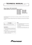
Special installations (Wall hanging)
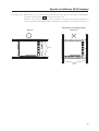
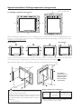
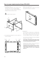
Securing method: Basically, the unit is secured as indicated below. Keep open all areas other than the shaded parts.
The fixing method marked
cannot be used for the unit.
When the unit is fixed on a structure, select a structure of the proper thickness and height. Care
must also be taken regarding the number of fixing bolts to be used (see “3.4.1 Fixing on a structure”).
Bad example of blocking exhaust
<Incorrect>
<Correct>
Beams
Beams
27
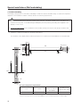
Special installation (Wall hanging)
A
B
50mm
B
Do not block this area at either the left or right.
10mm
Basically, it is not recommended to operate this display in any confined space.
In the event that you are going to use this display in a closed space, make sure to observe the
following requirements in accordance with the above drawing.
B ≥ 100mm
* No limitations of upper and lower clearances for the plasma display
Working temperature requirements
Clearance A to the wall
VIDEO
PC-9800 (56.4Hz)
Machintosh (66.7Hz)
PC-9800 (70.1Hz)
VGA (72.8Hz, 75Hz)
Less than 50 mm
0~30°C
VGA (60HZ)
0~30°C
Not usable
50 mm or more
0~40°C
0~40°C
0~35°C
* The same conditions apply to the working temperature requirements for a speaker system (PDP-S03-LR).
* In case the clearance A to the wall is 50 mm or more, the same working temperature conditions apply when
mounting the down converter.
28
Special installations (Wall hanging)
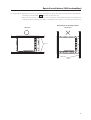
Securing method: Basically, the unit is secured as indicated below. Keep open all areas other than the shaded parts.
The fixing method marked
cannot be used for the unit.
When the unit is fixed on a structure, select a structure of the proper thickness and height. Care
must also be taken regarding the number of fixing bolts to be used (see “3.4.1 Fixing on a structure”).
Bad example of blocking exhaust
<Incorrect>
<Correct>
Beams
Beams
29
Special installations (Wall embedding)
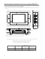
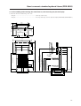
3.4.3 Wall embedding
This display is designed to accommodate embedding in a wall. Note that the allowable range of outside-air temperature
depends on the installation conditions. Please observe the following requirements:
1 Use a metal mounting fixture that does not block the side slits or the back ventilation holes, and attach at a
minimum of four points. To avoid breaking the PDP panel, limit any twisting or bending stress applied to the
display to 1 mm or less.
2 Do not use cable clamps for this installation method. Cable clamps can interfere with proper ventilation and
result in device failure.
3 Installation conditions and ambient operating temperatures:
(1) If the back of the display will be unobstructed (If there is no obstruction within 300 mm from the backside):
100 mm
MAX 20 mm
X
A
Y
A
A
Exhaust
Intake
100 mm
100 mm
100 mm
A
B
X-Y space temperature requirements
A size
150 mm or more
VIDEO
0~40°C
PC-9800 (56.4Hz)
Machintosh (66.7Hz)
VGA (60Hz)
0~40°C
PC-9800 (70.1Hz)
VGA (72.8Hz, 75Hz)
0~40°C
* The same conditions apply to the working temperature requirements for a speaker system (PDP-S03-LR).
* When mounting the down converter (PDA-4003), the same working temperature conditions apply.
30
Special installations (Wall embedding)
Securing method: Basically, the unit is secured as indicated below. Keep open all areas other than the shaded parts.
The fixing method marked
cannot be used for the unit.
When the unit is fixed on a structure, select a structure of the proper thickness and height. Care
must also be taken regarding the number of fixing bolts to be used (see “3.4.1 Fixing on a structure”).
Bad example of blocking exhaust
<Incorrect>
<Correct>
Beams
Beams
31
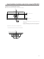
Special installations (Wall embedding)
50mm or more
Y
Punching net
X
100mm or more
100mm or more
100mm
or more
50mm
10mm
Aperture efficiency 50%
or more
100mm
or more
Working temperature requirements
VIDEO
PC-9800 (56.4Hz)
Machintosh (66.7Hz)
0~40°C
VGA (60Hz)
0~40°C
PC-9800 (70.1Hz)
VGA (72.8Hz, 75Hz)
0~35°C
* When mounting the down converter (PDA-4003), the same working
temperature conditions apply.
32
Special installations (Wall embedding)
Securing method: Basically, the unit is secured as indicated below. Keep open all areas other than the shaded parts.
The fixing method marked
cannot be used for the unit.
When the unit is fixed on a structure, select a structure of the proper thickness and height. Care
must also be taken regarding the number of fixing bolts to be used (see “3.4.1 Fixing on a structure”).
Bad example of blocking exhaust
<Incorrect>
<Correct>
Beams
Beams
33
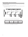
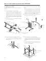
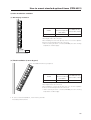
Special installation (Putting in a box) Rear side mesh
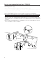
3.4.4 When the display is put in a box
Operating this display in confined spaces is not recommended.
• If the display is to be used in confined spaces, observe the following conditions shown in the drawing in a page to the
right:
A ≥ 50
B ≥ 50
C ≥ 10
D ≥ 50
Use a mesh with aperture efficiency of 50% or more.
• Keep the temperature in the closed space "Y" and the open space "X" less than the following temperature
range. In particular, the space "Y" should be ventilated sufficiently by the air conditioner or fan so that hot air
is not trapped in the space. Thus, everywhere in "Y" must be kept less than the following temperature range. If hot
air remains in the closed space, the temperature may rise, causing a malfunction or fire. As a precaution in case of
accidents, the inner wall should have sufficient heat resistance or fire resistance.
Usage temperature conditions (BOX air temperature)
VIDEO
0~35 °C
PC-9800 (56.4Hz)
Machintosh (66.7Hz)
VGA (60Hz)
0~35 °C
PC-9800 (70.1Hz)
VGA (72.8Hz, 75Hz)
0~35 °C
* When mounting the down converter (PDA-4003), the same working temperature conditions apply.
34
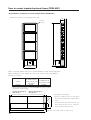
Special installation (Putting in a box) Rear side mesh
Mesh
Mesh
Intake side
Outside air temperature measuring point
10mm
Exhaust side
A
A
B
10mm
B
D
C
B+50mm
B+50mm
Rear view (the following area should be made of mesh)
Mesh with aperture efficiency of 50% or more
614mm
614mm
Area 900 cm2 or more
B+50mm
B+50mm
Minimum area
900 cm2 or more
A ≥ 50
B ≥ 50
C ≥ 10
D ≥ 50
A+50mm 150mm or more
150mm or more A+50mm
35
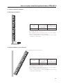
Special installation (Putting in a box) Mesh (side)
Operating this display in confined spaces is not recommended.
• If the display is to be used in confined spaces, observe the following conditions shown in the drawing in a page to the
right:
A ≥ 50
B ≥ 50
C ≥ 10
D ≥ 50
Use a mesh with aperture efficiency of 50% or more.
• Keep the temperature in the closed space "Y" and the open space "X" less than the following temperature
range. In particular, the space "Y" should be ventilated sufficiently by the air conditioner or fan so that hot air
is not trapped in the space. Thus, everywhere in "Y" must be kept less than the following temperature range. If hot
air remains in the closed space, the temperature may rise, causing a malfunction or fire. As a precaution in case of
accidents, the inner wall should have sufficient heat resistance or fire resistance.
Usage temperature conditions (BOX air temperature)
VIDEO
0~35 °C
PC-9800 (56.4Hz)
Machintosh (66.7Hz)
VGA (60Hz)
0~35 °C
PC-9800 (70.1Hz)
VGA (72.8Hz, 75Hz)
0~30 °C
* When mounting the down converter (PDA-4003), the same working temperature conditions apply.
36
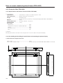
Special installation (Putting in a box) Mesh (side)
Intake side
Mesh
Exhaust side
100 mm
Mesh
Outside air temperature
measuring point
A
A
B
10mm
B
C
B+50 mm
B+50 mm
D
564 mm
564 mm
Minimum area 500 cm2
or more
A ≥ 50
B ≥ 50
C ≥ 10
D ≥ 50
B+100 mm
100 mm C
or more
(Intake side)
B+100 mm
Mesh with aperture efficiency of 50% or more
100 mm
or more
(Exhaust side)
C
37
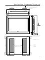
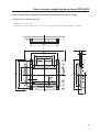
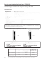
Special installation (Wall hanging (vertically wall-hanging equipment))
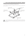
3.4.5 Wall hanging (vertically wall-hanging equipment)
This display is designed to accommodate a range of wall installations. For this type of installation, carefully consider all
installation specifics before beginning work, since these factors can significantly affect the temperature of the air
surrounding the display. Please observe the following requirements:
1 Use plate metal that keeps all single holes clear and has dimensions no larger than those given in the following
table.
2 Leave adequate ventilation space between the wall and the display.
3 Mount a metal plate with sufficient strength at each of the four positions indicated in the following figure (fourpoint stopping).
Mounting the display on the wall involves danger. Be sure to take double safety measures.
4 Recommended ambient operating temperatures are listed in the following table. Operate the display within this
temperature range.
5 The surface of the wall should closely approximate a perfectly flat plane. Keep deformation pressures on the
display, such as twisting and bending, at or below 1 mm.
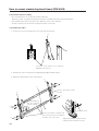
Wall
A
Do not block this area to the left or right.
40mm
75mm 75mm
694 mm (center indicated)
Do not block this area on either the top or the bottom.
75mm 75mm
40mm
50mm
50mm
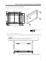
Working temperature requirements
Clearance A to the wall
38
VIDEO
PC-9800 (56.4Hz)
Machintosh (66.7Hz)
PC-9800 (70.1Hz)
VGA (72.8Hz, 75Hz)
Less than 50 mm
0~30°C
VGA (60Hz)
0~30°C
Not usable
50 mm or more
Less than 100 mm
0~40°C
0~40°C
0~30°C
Less than 100 mm
0~40°C
0~40°C
0~35°C
* The same conditions apply to the working temperature requirements for a speaker system (PDP-S03-LR).
* In case the clearance A to the wall is 50 mm or more, the same working temperature conditions apply
when mounting the down converter.
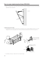
Special installation (Wall hanging (vertically wall-hanging equipment))
Securing method: Basically, the unit is secured as indicated below. Keep open all areas other than the shaded parts.
The fixing method marked
cannot be used for the unit.
When the unit is fixed on a structure, select a structure of the proper thickness and height. Care
must also be taken regarding the number of fixing bolts to be used (see “3.4.1 Fixing on a structure”).
<Correct>
Bad example of blocking exhaust
<Incorrect>
Beams
Beams
39
Special installation (Wall hanging (vertically wall-hanging equipment))
B
50mm
A
B
C
50mm
C
Basically, it is not recommended to operate this display in any confined space.
In the event that you are going to use this display in a closed space, make sure to observe the following requirements
in accordance with the above drawing.
B ≥ 100mm
C ≥ 100mm
Working temperature requirements
Clearance A to the wall
VIDEO
PC-9800 (56.4Hz)
Machintosh (66.7Hz)
50 mm or more and/or 100 mm or less
0~35°C
VGA (60Hz)
0~35°C
100 mm or more
0~40°C
0~40°C
PC-9800 (70.1Hz)
VGA (72.8Hz, 75Hz)
30°C
0~35°C
* The same conditions apply to the working temperature requirements for a speaker system (PDP-S03-LR).
* When mounting the down converter (PDA-4003), the same working temperature conditions apply.
40
Special installation (Wall hanging (vertically wall-hanging equipment))
Securing method: Basically, the unit is secured as indicated below. Keep open all areas other than the shaded parts.
The fixing method marked
cannot be used for the unit.
When the unit is fixed on a structure, select a structure of the proper thickness and height. Care
must also be taken regarding the number of fixing bolts to be used (see “3.4.1 Fixing on a structure”).
<Correct>
Bad example of blocking exhaust
<Incorrect>
Beams
Beams
41
Special installation (Wall embedding (vertically wall-embedding equipment))
3.4.6 Wall embedding (vertically wall-embedding equipment)
This display is designed to accommodate embedding in a wall. Since the allowable range of outside-air temperature
depends on the installation conditions. Please observe the following conditions:
1 Use a metal mounting fixture that does not block the side slits or the back ventilation holes, and attach at a
minimum of four points. To avoid breaking the PDP panel, limit any twisting or bending stress applied to the
display to 1 mm or less.
2 Do not use cable clamps for this installation method. Cable clamps can interfere with proper ventilation and
result in device failure.
3 Installation conditions and ambient operating temperatures:
(1) If the space behind the wall is open (If there is no obstruction within 300 mm from the backside):
100 mm
A
100 mm
A
C
A
Exhaust
Install the display with
the fan on top.
100
mm
100
mm
A
Working temperature requirements
PC-9800 (56.4Hz)
A size
VIDEO
Machintosh (66.7Hz)
VGA (60Hz)
60 mm or less
60 mm or more and/or 150 mm or less
0~40°C
0~40°C
0~40°C
0~40°C
PC-9800 (70.1Hz)
VGA (72.8Hz, 75Hz)
0~40°C
0~35°C
* The same conditions apply to the working temperature requirements for a speaker system (PDP-S03-LR).
* When mounting the down converter (PDA-4003), the same working temperature conditions apply.
42
Special installation (Wall hanging (vertically wall-hanging equipment))
Securing method: Basically, the unit is secured as indicated below. Keep open all areas other than the shaded parts.
The fixing method marked
cannot be used for the unit.
When the unit is fixed on a structure, select a structure of the proper thickness and height. Care
must also be taken regarding the number of fixing bolts to be used (see “3.4.1 Fixing on a structure”).
<Correct>
Bad example of blocking exhaust
<Incorrect>
Beams
Beams
43
Special installations (Wall hanging (Vertically installing this display by embedding in the wall)
(2) When there is a closed space behind the wall.
Punching net
B
A
Punching
net
50mm 50mm
B
Aperture ratio 50%
or more
C
Punching net
C
Punching net
B ≥ 100
C ≥ 100
Basically, it is not recommended to operate this display in a confined space.
In the event that you are going to use this display in a closed space, make sure to observe the following requirements
in accordance with the above drawing.
Clearance A to the wall
100mm or more
VIDEO
0~35°C
PC-9800 (56.4Hz)
Machintosh (66.7Hz)
VGA (60Hz)
0~35°C
PC-9800 (70.1Hz)
VGA (72.8Hz, 75Hz)
0~30°C
* The same conditions will apply to the working temperature requirements for a speaker system (PDP-S03-LR).
* When mounting the down converter (PDA-4003), the same working temperature conditions apply.
44
Special installation (Wall hanging (vertically wall-hanging equipment))
Securing method: Basically, the unit is secured as indicated below. Keep open all areas other than the shaded parts.
The fixing method marked
cannot be used for the unit.
When the unit is fixed on a structure, select a structure of the proper thickness and height. Care
must also be taken regarding the number of fixing bolts to be used (see “3.4.1 Fixing on a structure”).
<Correct>
Bad example of blocking exhaust
<Incorrect>
Beams
Beams
45
Special installation (Ceiling suspension (using wires))
3.4.7 Ceiling suspension (using wires)
Mount the display with the
fans on the upper side.
C
C
A
B
B
A
D
D
When suspending the display by wires, use a combination of two mounting rows, as shown in the diagram above (rows
A - B or C - D, from rows A - D). This is done to safeguard against subjecting the display to twisting forces. Use a
minimum of four mounting points.
Good example
Bad example
×
Use the following metal fixture to keep load from centering on the two mounting points at the top. As discussed in
3.4.1 Fixing on a struc, avoid blocking any ventilation holes other than those in the shaded (
).
When attaching cables to the ceiling, install two cables at two independent points for safety.
Wire
Wire
If the display is
suspended close to a
wall, provide at least
300 mm clearance
between that wall
and the display.
Metal fixture
Metal fixture
Working temperature requirements
Use mounting screws with minimum strength equal to that of mild steel cable, or
stronger screws with hexagonal socket heads.
The cable must be capable of supporting a load four times as heavy as the total weight
of the display (30.8 kg <31.6 kg>) plus the weight of the metal fixture, if one is used.
Provide auxiliary back-up cables to safeguard against breakage of main cables due to
earthquakes etc..
< > shows the PDP-V401E.
46
VIDEO
0~40°C
PC-9800 (56.4Hz)
PC-9800 (70.1Hz)
Machintosh (66.7Hz)
VGA (72.8Hz, 75Hz)
VGA (60Hz)
0~40°C
0~40°C
* When mounting the down converter (PDA-4003), the same
working temperature conditions apply.
Special installation (Ceiling suspension (using wires))
Should the distance between the wall face and the unit be 300 mm or less, treat the clearance in the rear cover of the
pop or that of the fixture nearer to the wall as the clearance A and apply the wall hanging conditions in 3.4.2.
wall hanging.
Metal fixture
Metal fixture
PDP
A
A or more
Wall
47
Special installation (Installation with the screen downward)
3.4.8 Installation with the screen downward
This display is designed to be installed with the screen downward, but certain uses can interfere with proper ventilation.
Please observe the following conditions:
1 Use plate metal that keeps all single holes clear and has dimensions no larger than those given in the following
table.
2 Leave adequate ventilation space between the display and the ceiling.
3 Use plate metal having sufficient strength (incorporating a safety factor of approximately four), and secure at the
four points indicated in the following drawing (four-point mounting). Mounting plate metal on a ceiling involves
certain hazards. Make sure you provide adequate back-up safety measures.
4 Recommended ambient operating temperatures are given in the following table. Operate the display within this
range of temperatures.
5 The ceiling should closely approximate a perfectly flat plane. Keep deformation pressures applied to the display,
such as twisting and bending, at or below 1 mm.
50mm
Do not block this area on either the top or the bottom.
Ceiling
40mm
40mm
Do not block this area on either the top or the bottom.
A
75mm 75mm
694 mm (center indicated)
75mm 75mm
Ceiling
Working temperature requirements
PC-9800 (56.4Hz)
A size
VIDEO
Machintosh (66.7Hz)
VGA (60Hz)
50 mm or more
0~35°C
0~35°C
PC-9800 (70.1Hz)
VGA (72.8Hz, 75Hz)
0~35°C
* The same conditions apply to the working temperature requirements for a speaker system (PDP-S03-LR).
* When mounting the down converter (PDA-4003), the same working temperature conditions apply.
48
Special installation (Installation with the screen downward)
Securing method: Basically, the unit is secured as indicated below. Keep open all areas other than the shaded parts.
The fixing method marked
cannot be used for the unit.
When the unit is fixed on a structure, select a structure of the proper thickness and height. Care
must also be taken regarding the number of fixing bolts to be used (see “3.4.1 Fixing on a structure”).
Bad example of blocking exhaust
<Correct>
<Incorrect>
Beams
Beams
49
Special installation (Ceiling embedding)
3.4.9 Ceiling embedding
This display is designed to accommodate embedding in a ceiling. Note that the allowable range of outside-air temperature
depends on the installation conditions. Please observe the following requirements:
1 Use a mounting fixture with a shape that does not block ventilation holes on the back or disturb ventilation in
any way, and secure the display at four or more points. Moreover, when installing this display, ensure that the
deformation such as twisting and bending of this display can be kept within 1 mm. Otherwise, it is likely that
PDP panel will cause cracks.
2 Do not use cable clamps for this installation method. Cable clamps can interfere with proper ventilation and
result in device failure.
3 Installation conditions and ambient operating temperatures:
(1) When the space above the ceiling is not enclosed (If there is no obstruction within 300 mm from the backside):
Intake (holes other than
100 mm that of fan)
Exhaust
A
A
100 mm
100 mm
100 mm
A
Working temperature requirements
Clearance A to the wall
150 mm or less
VIDEO
0~40°C
PC-9800 (56.4Hz)
Machintosh (66.7Hz)
VGA (60HZ)
0~40°C
PC-9800 (70.1Hz)
VGA (72.8Hz, 75Hz)
0~35°C
* The same conditions apply to the working temperature requirements for a speaker system (PDP-S03-LR).
* When mounting the down converter (PDA-4003), the same working temperature conditions apply.
50
Special installation (Ceiling embedding)
Securing method: Basically, the unit is secured as indicated below. Keep open all areas other than the shaded parts.
The fixing method marked
cannot be used for the unit.
When the unit is fixed on a structure, select a structure of the proper thickness and height. Care
must also be taken regarding the number of fixing bolts to be used (see “3.4.1 Fixing on a structure”).
Bad example of blocking exhaust
<Incorrect>
<Correct>
Beams
Beams
51
Special installation (Installation on the floor)
3.4.10 Installation on the floor
This display is designed to accommodate floor installation, but certain specific installations may interfere with adequate
ventilation. Always observe the following conditions:
1 Use plate metal that keeps all single holes clear and has dimensions no larger than those given in the following
table.
2 Leave adequate ventilation space between the display and the floor.
3 Use plate metal having sufficient strength, and attach at the four points indicated in the following drawing (fourpoint mounting).
4 Recommended ambient operating temperatures are listed in the following table. Operate the display within this
temperature range.
5 The ceiling should closely approximate a perfectly flat plane. Keep deformation pressures upon the display, such
as twisting and bending, at or below 1 mm.
Floor
Floor
Do not block this area at the top or bottom.
50mm
Do not block this area at the left or right.
40mm
A
40mm
50mm
Floor
75mm 75mm
694 mm (center indicated)
75mm 75mm
Working temperature requirements
PC-9800 (56.4Hz)
A size
50 mm or more
VIDEO
0~40°C
Machintosh (66.7Hz)
VGA (60Hz)
0~40°C
PC-9800 (70.1Hz)
VGA (72.8Hz, 75Hz)
0~35°C
* The same conditions apply to the working temperature requirements for a speaker system (PDP-S03-LR).
* When mounting the down converter (PDA-4003), the same working temperature conditions apply.
52
Special installation (Installation on the floor)
Securing method: Basically, the unit is secured as indicated below. Keep open all areas other than the shaded parts.
The fixing method marked
cannot be used for the unit.
When the unit is fixed on a structure, select a structure of the proper thickness and height. Care
must also be taken regarding the number of fixing bolts to be used (see “3.4.1 Fixing on a structure”).
Bad example of blocking exhaust
<Correct>
<Incorrect>
Beams
Beams
53
Special installation (Installation under the floor)
3.4.11 Installation under the floor
• If protective glass or similar material is used, the following installation conditions must be observed:
Floor
Protective glass surface
C
C
600 mm or more
600 mm or more
Intake
Exhaust
G
F
B
B
C
C
E
A
Exhaust fan
Exhaust port
Tempered glass, etc. (permeable)
A + 50 mm
or less
60 mm
or less
A + 50 mm
or less
Exhaust
50mm
60 mm or
less
Flow of air from the air conditioner
B
D
Intake port
B
| Looking in the direction of the arrow (see the next page)
If the display is used in the closed space, observe the following conditions in the above environment:
A ≥ 20 mm (clearance between the protective glass and PDP)
B ≥ 100 mm (clearance between the PDP and side wall)
C ≥ 50 mm (clearance between the PDP and side wall)
D ≥ 290 mm (clearance between the surface of the PDP and the mounting surface under
the floor)
E ≥ D – 65 mm
F ≥ 180 mm
G ≥ 600 mm
VIDEO
PC-9800 (56.4Hz)
Machintosh (66.7Hz)
PC-9800 (70.1Hz)
VGA (72.8Hz, 75Hz)
Without exhaust fan
0~30°C
VGA (60Hz)
0~30°C
Not usable
With exhaust fan
0~35°C
0~35°C
0~35°C
* When mounting the down converter (PDA-4003), the same working temperature conditions apply.
54
Special installation (Installation under the floor)
Conditions for embedding under the floor
| Looking in the direction of the arrow (see the previous page)
C. L.
600 mm or more
a
A + 50 mm or less
a
b
60 mm or less
a=b
The size of the intake port is the same as that of the
exhaust port.
For the exhaust port only, add a fan at the position
indicated in the left figure (in the case of a single fan).
Fan placement....Place a fan in an upper position.
* The maximum air flow rate of the fan is 2.0 m3/min.
C. L.
In the case of two fans:
a
a
a
a
55
Special installation (Installation under the floor)
Securing method: Basically, the unit is secured as indicated below. Keep open all areas other than the shaded parts.
The fixing method marked
cannot be used for the unit.
When the unit is fixed on a structure, select a structure of the proper thickness and height. Care
must also be taken regarding the number of fixing bolts to be used (see “3.4.1 Fixing on a structure”).
<Correct>
<Correct>
Beams
Beams
Bad example of blocking exhaust
<Incorrect>
Beams
Beams
56
Do not install the horizontal beam at
the same time as the vertical beam.
Special installation (Installation under the floor)
57
Special installation (Installation under the floor (using the PDM-4001))
3.4.12 Installation under the floor (using the PDM-4001)
• If protective glass or similar material is used, the multi-installation fixture (PDM-4001) shown in the following figure is
very useful.
Floor
Protective glass surface
C
C
600 mm or more
600 mm or more
Intake
Exhaust
B
B
C
C
A
Exhaust fan
Exhaust port
A + 50 mm
or less
Tempered glass, etc. (permeable)
291mm
A + 50 mm
or less
Exhaust
60 mm
or less
60 mm or
less
Flow of air from the air conditioner
B
50mm
Multi-installation fixture (PDM-4001)
Intake port
B
| Looking in the direction of the arrow (see the next page)
If the display is used in the closed space, observe the following conditions in the above environment:
A ≥ 20 mm (clearance between the protective glass and PDP)
B ≥ 100 mm (clearance between the PDP and side wall)
C ≥ 50 mm (clearance between the PDP and side wall)
PC-9800 (56.4Hz)
VIDEO
Without exhaust fan
With exhaust fan
0~30°C
0~35°C
Machintosh (66.7Hz)
VGA (60Hz)
0~30°C
0~35°C
PC-9800 (70.1Hz)
VGA (72.8Hz, 75Hz)
Not usable
0~35°C
* When mounting the down converter (PDA-4003), the same working temperature conditions apply.
58
Special installation (Installation under the floor (using the PDM-4001))
Conditions for embedding under the floor:
| Looking in the direction of the arrow (see the previous page)
C. L.
600 mm or more
a
A + 50 mm or less
a
b
60 mm or less
a=b
The size of the intake port is the same as that of the
exhaust port.
For the exhaust port only, add a fan at the position
indicated in the left figure (in the case of a single fan).
Fan placement....Place a fan in an upper position.
* The maximum air flow rate of the fan is 2.0 m3/min.
C. L.
In the case of two fans:
a
a
a
a
59
Special installation (Horizontal connections)
3.4.13 Horizontal connections
While the display is designed to accommodate side-by-side installations, keep in mind that specific installation
configurations may affect ventilation. Observe the following requirements:
1 The following table lists the operating temperature conditions. Use the units under conditions that keep the
outside atmosphere in this range.
A
Partition
50mm
Unit C
50mm
Unit B
50mm
Unit A
50mm
50mm
50mm
40mm
In case of lateral connections, ensure that left and right partitions are provided.
Be careful to install the partitions so that the air on the left and right backside of the set is not
mixed up.
Clearance A to the wall
50 mm or more
VIDEO
0~35°C
PC-9800 (56.4Hz)
Machintosh (66.7Hz)
VGA (60HZ)
0~35°C
PC-9800 (70.1Hz)
VGA (72.8Hz, 75Hz)
0~35°C
* The same conditions apply to the working temperature requirements for a speaker system (PDP-S03-LR).
* When mounting the down converter (PDA-4003), the same working temperature conditions apply.
* For the securing method, see 3.4 Special installations and 3.4.2 Wall hanging.
60
Special installation (Vertical connections)
3.4.14 Vertical connections
This machine is designed to be used vertical connection, but some operations under vertical connection may adversely
affect ventilation in the machine. Therefore, observe the following conditions for safe operation:
1 Installation of up to three units (Vertical connection)
The following table lists the operating temperature conditions. Use the units under conditions that keep the
outside atmosphere in this range.
PC-9800 (56.4Hz)
Clearance A to the wall
50 mm or more
VIDEO
0~35°C
Machintosh (66.7Hz)
VGA (60HZ)
0~35°C
PC-9800 (70.1Hz)
VGA (72.8Hz, 75Hz)
0~35°C
* The same conditions apply to the working temperature requirements for a speaker system (PDP-S03-LR).
* When mounting the down converter (PDA-4003), the same working temperature conditions apply.
Wall
Partition
A
Make sure to
mount them
so that they
will not block
any exhaust
holes.
50mm
50mm
* For the securing method, see 3.4 Special installations and 3.4.2 Wall hanging.
61
Before making adjustments
5.1 Before Beginning Adjustments
You can make adjustments to the unit in the following ways:
• With the operating panel of the main unit
• With the remote control unit
• With a PC (through RS-232C control)
Make sure you’ve thoroughly read and understood the following before making any adjustments.
5.1.1 Operating mode
The unit has the following four major operating modes:
Standby Status
STANDBY/ON
<POF>
1 Normal Operating Mode
MENU
(Note 1)
<PON>
<
indicates operating mode and
status.
indicates button operations on
the remote or on the main unit’s
operating panel.
> indicates RS-232C command operations.
<AJY>
<AJN>
DISPLAY
MENU
2 Menu Mode
PICTURE PARAMETER
MENU
STANDBY/ON
3 Integrator Mode
4 RS-232C Adjustment Mode
PICTURE PARAMETER
CONTRAST
CONTRAST
BRIGHT.
COLOR (Note:1)
TINT (Note:1,4)
SHARPNESS (Note:1)
CLK.FRQ. (Note:2)
CLK.PHS. (Note:2)
HOR.POS. (Note:2)
VER.POS. (Note:2)
INIT.
SCART RGB (Note:6)
BRIGHT.
COLOR (Note:1)
TINT (Note:1,4)
SHARPNESS (Note:1)
CLK.FRQ. (Note:2)
CLK.PHS. (Note:2)
HOR.POS.
VER.POS.
INIT.
See the description provided in
“5.3 Outer control by RS-232C”.
WHITE BALANCE
R HIGH
G HIGH
B HIGH
R LOW
G LOW
B LOW
INIT.
ADDITIONAL SET UP
COLOR MODE
BAUD RATE
AUTO RGB2
MP MODE (Note:5)
NTSC MASK (Note:4)
FULL MASK
OSD
FOUR METER (Note:3)
TOTAL INITIALIZE
Note 1:
Note 2:
Note 3:
Note 4:
Only when VIDEO and Y/C are input.
Only when RGB1 and RGB2 are input.
Only indication
Only when NTSC signal, no signal, or no applicable signal is input (VGA, Macintosh, PC-9800 inputs).
Cannot adjust when PAL signals are input <PAL signals can be input only for PDP-V402E>.
Note 5: Only when signals other than the NTSC signal are input.
Note 6: PDP-V402 only
154
Functions and features of standard optional items
4.1 Functions and features of standard metal fixtures
Our plasma display (PDP-V402 <PDP-V402E>) features a large screen, high luminance, and high picture quality. In
addition, the plasma display is so light and thin that it can be installed in a far wider area than competing displays now
on the market.
The PDP-V402 <PDP-V402E> is designed so that it can be installed in different ways, as we have taken the operating
environment and installation structure in consideration. To take advantage of this flexibility in installation methods, you
can select one of the following standard metal fixtures:
¶ Down converter: PDA-4003
This is a high performance down converter, which allows our plasma display PDP-V402 to display the XGA (images
of 1024 x 768 pixels). It enables the plasma display to deliver considerably sharp images, minimizing missing information
such as very fine characters or lines.
¶ Tilting stand: PDK-4001
The angle of the PDK-4001 tilting stand can be adjusted in a range from 0° to 20° from vertical. With this stand, you
can adjust the tilt of a plasma display installed on a desk or floor to suit your eyes.
¶ One-sided, ceiling-suspension the metal fixture for the plasma display: PDK-4002
With this simple support fixture, you can adjust the installation angle between ± 45° from right to left and up to 25°
down from horizontal. The depth of the display with this metal fixture at the time of installation is less than or equal
to 170 mm when the display is installed vertically. This fixture can cover a large area depending on the application.
¶ Double-sided, ceiling-suspension the metal fixture for the plasma display: PDK-4003
The metal fixture for double-sided installation makes good use of the display’s thin, light structure. This fixture
enables double-sided installations of less than or equal to 470 mm when the display is installed vertically, something
which is not possible with other displays on the market.
¶ Ceiling-suspension metal fixture for the plasma display (hand screw type): PDK-4004
This low-cost metal fixture uses a bolt, and allows you to adjust the angle up to 25° down from horizontal. It is
suitable for installing the display in rooms having a standard ceiling height (2.40 – 2.70 m).
¶ PDP bracket: PDK-4005
The PDK-4005 bracket can be used when handling the display during transport or installation. You can also use this
bracket as a frame for wire-hanging or wall-installation. It is best suited to rental applications that require speedy
installation and simple and safe mounting.
¶ Wall-mounting metal fixture for plasma display: PDK-4006
This mounting fixture permits adjustable installation angles between 0 and 25 degrees. When installation is complete,
the installed depth should be 125 mm or less (for vertical installations without optional speaker system). Adjust the
tilt to for best visibility, depending on the particular use.
¶ Mobile cart: PDK-5008
This is a carryable stand, which is stable enough for one person to freely transfer the plasma display.
It is possible to adjust the height and angle of the screen to meet the sightline of the viewers, depending on the
purpose.
¶ Multi-display bracket for plasma display: PDM-4001
The multi-display bracket allows you to take full advantage of the thinness of the plasma display. With plasma
displays of 300 mm depth or less, which was virtually impossible with conventional display, installation of a maximum
4 x 4 multiple displays (3676 x 2868 mm) is possible. Furthermore, once the multiple displays are installed, maintenance
of the displays is possible using front access.
¶ Protective filter: PDA-4002
This filter is used to improve the durability of the plasma display for industrial use.
This filter prevents the plasma display from being damaged or stained due to malicious acts, and improves the
strength of the front of the panel. When the filter is mounted, the anti-reflection coating prevents the quality of
images from deteriorating.
62
Functions and features of standard optional items
¶ Speaker system: PDP-S03-LR
The sound system employs a vertical twin-system, composed of a 2.5-cm dome corn-type tweeter at the center and
newly-developed elliptical drivers 4.5 cm in width, arranged vertically. The resulting configuration system produces
rich, stable sound fields.
Only 7.4-cm wide, the cabinet reproduces a rich and dynamic sound range. (When the speaker is mounted to the
main body of the plasma display, the operation panel on the main body may not be used.)
The work of assembling and installing the metal fixture and mounting the plasma display must
always be performed by two people.
Caution
63
Handling standard optional items
4.2 Handling standard metal fixtures
4.2.1 Precautions on handling metal fixtures
This chapter describes how to install and handle metal fixtures specially designed for plasma displays sold by us,
PIONEER. We sell this unit on the premise that it will be installed by specialist vendors with sufficient technical skill.
The plasma display must be installed by a specialist in this work or by the dealer from which you made your purchase.
4.2.2 Precautions for vendors performing the installation
1) Before installation
Strictly observe the instructions in “3.1 Installation environment”.
2) Installation
Thoroughly read the contents of this chapter and observe the instructions.
For safety, make sure the work is performed by more than one person.
“Sufficient strength to withstand” means sufficient strength to withstand a weight four times that of the main body
including the metal fixture.
3) After installation
After installing the metal fixture, check it for strength and make sure there are no loose screws. When the plasma
display is mounted, check the installation again.
4) Delivery to the customer
(1) Precautions on operation
¶ Precautions
After finishing the above checks, the installing vendor must describe the following precautions to the customer.
Even if the construction is perfect, handling the metal fixture improperly can undermine the integrity of the installation.
You should explain precautions on handling to the customer so that the customer can understand how to handle
the display.
¶ Convenient use of the plasma display
• If the display is not mounted properly, please ask the installing vendor to check and repair it.
• To prevent the display from falling or similar accidents, do not try to adjust the angle or height of the plasma
display yourself. Please ask the installing vendor to adjust it (Except the PDK-4001).
¶ Do not do the following.
The following actions are inherently dangerous. Exercise caution in handling the metal fixtures.
• Applying loads by pushing or pulling.
• Spilling water on the fixture.
• Placing something on the fixture.
• Touching screws that are part of the fixture.
(2) Notes for vendor performing the installation (Japanese only)
Once the installation is completed and checked and the above precautions have been explained to the customer,
the installing vendor must enter certain data in the Vendor’s installation notes and give these notes to the customer.
(3) Periodic inspection
Parts that are not visible from the exterior, which are either inside the display or part of the floor or ceiling on which
the plasma display is mounted, may age without obvious signs until the display falls from the mounting fixtures.
Advise the customer to ask the installing vendor or a specialist to periodically inspect the fixture and plasma display.
64
How to mount standard optional items
(Stand: an accessory to PDP-V402 <PDP-V402E>)
4.3 Stand (an accessory to PDP-V402 <PDP-V402E>)
4.3.1 Installing the stand
1.
Attach the stand to the display
using M8 commercial screws
whose length equals the thickness
of the table to which the fixture is
attached plus 25 mm.
3.
Insert the main body of the plasma
display into the stand.
4.
Fix the main body to the stand with
the washers and bolts provided.
Front
590
100
Rear
100
2.
Remove hole rivets A and A’ with
a coin or the like.
A
A'
For this work, use a hexagonal
wrench.
This unit weighs 30.8 kg <31.6 kg>. In
addition, it is unstable due to its small depth,
and should be unpacked and carried by at
Caution
least two persons.
< > shows the PDP-V402E.
65
How to mount standard optional items
(Stand: an accessory to PDP-V402 <PDP-V402E>)
4.3.2 Outer-dimensions diagram (Unit: mm)
88
250
92
64.8
70
25
163
22
736
714
916
250
100
70
66
66
49
65
11
22.4
24.2
11
65
1.5
How to mount standard optional items (PDA-4003)
4.4 Down converter PDA-4003
4.4.1 Specifications
Input/output terminals
Input ............................................................ D-sub 15pin
Accessories
Remote control ............................................................ 1
Output .......................................................... D-sub15pin
Remote control satellite input (Sold separately)
Screw rivets .................................................. 8 (spare 4)
Rubber cushion ............................................................ 4
.................................................................. MINI DIN4pin
DC supply connector ........................................ Mini-jack
AA manganese battery ................................................. 2
D-sub 15 pin cable ........................................................ 1
Output signal
AC adaptor ................................................................... 1
(AC 100 V - 240 V 50/60 Hz DC 9.3 V Rating 3 A)
Resolution, refresh rate ................ 640 X 480(VGA),60Hz
Belcro ........................................................................... 2
Power Cord .................................................................. 1
Miscellaneous
Power supply .................................................... DC 9.3V
Binder ......................................................................... 10
Cable strap ................................................................... 1
Current (DC 9.3V) .................................................... 0.8A
External dimension ..........................................................
Operating Instructions .................................................. 1
Warranty Card .............................................................. 1
.................... 338(Width) X 28(Height) X 150(Depth) mm
Weight ....................................................................... 1kg
The specifications and external appearance of the product may change without prior notice due to constant improvements.
Input Signals
The input signals for the down converter are as shown below.
Resolution
(dots x lines)
Vertical Frequency
(Hz)
Horizontal Frequency
(kHz)
640 x 480
72.809
37.861
640 x 480
640 x 480
75.000
85.008
37.500
43.269
VASA Guidelines
800 x 600
800 x 600
56.250
60.317
35.156
37.879
VESA Standerd
800 x 600
800 x 600
75.000
85.061
46.875
53.674
1024 x 768
1024 x 768
60.004
70.069
48.363
56.476
1024 x 768
1024 x 768
75.029
84.997
60.023
68.677
13-inch monitor
16-inch monitor
640 x 480
832 x 624
66.670
74.502
35.000
49.693
19-inch monitor
1024 x 768
74.700
60.000
Display Mode
VGA
SVGA
XGA
Macintosh
VESA Standard
VASA Guidelines
VESA Standerd
67
How to mount standard optional items (PDA-4003)
Note 1) In case the signals for the full lines which are more than 845 lines are input, ''OUT OF RANGE'' will be indicated.
Note 2) Though it is not shown in the above table, in case the signals for the full lines which are equal to or less than 845
lines are input, the images will be shown, but there are some possibilities that the following problems might
happen:
1 The out-of-roundness may not be correct (Example: PC-9800/640 X 400 @ 56.4Hz)
2 Noise may be caused/images may be distorted.
3 Images may not be completely adjusted.
Please understand that these problems are out of the scope of our product warranty.
Moreover, in case that it is inevitable for you to input some interlaced signals, input by way of separate
synchronization.
In case you use G on Sync or composite synchronization to input, there is a chance that the resolution and
frequency of your signals may not be correctly identified.
Note 3) There are some older Macintosh PC models that can output both C on Synch and composite synchronization at
the same time. In such a case, there is a chance that the resolution and frequency of the signals may not be
correctly identified or the white balance may be disturbed. Therefore, basically, do not use such models.
Note 4) Macintosh is the registered trademark of Apple Computer Inc.
PC-9800 is the registered trademark of NEC Corporation.
4.4.2 Outline drawing (Unit: mm)
CL
CL
338
144.4
85
φ5.1
φ6
AAAX2750-A
φ6
DC IN 8.3V
0.8A
5.7
RGB OUT
RGB IN
RGB OUT
RGB IN
4.5
ON
4.4
OFF
SATELLITE REMOTE
DC8V
12mA MAX
(to JA-V15IR or JA-V150IR)
CL
OFF
ON
112.7
68
22
28
DC8V
12mA MAX
SATELLITE REMOTE
0.8A
DC IN 8.3V
17.9
12.2
306
150
φ6×5.1
19.6
325.2
How to mount standard optional items (PDA-4003)
4.4.3 The outline from setting up to adjusting of down converter
The following explains the outline from setting up to adjusting of down converter, when using PDP-V402, PDP-V402E
plasma display manufactured by our company.
Start
Open the section titled ''Before using
the down converter.''
Mount the cable strap
Mount the down converter on the rear
See the section titled ''Before using this down converter'' in Page 71.
See the section titled ''How to use a cable strap'' in Page 74.
Note) If it has already been mounted, there is no need for this work.
See the section titled ''Mounting on the plasma display'' in Page 72.
panel of the plasma display.
Connect the cables and the AC adapter.
See ''Connection'' in Page 76 and ''Connecting the power supply cord''
in Page 76 as well as ''How to mount the AC adapter'' in Page 73.
Carry out the styling of the cables.
See the section titled ''On styling of the cables'' for your reference in
Page 75.
Turn ON the power for the input signal
Note) Turn the input function of the plasma display to ''RGB2.''
source (including PC), the plasma
display and the down converter.
Input the FULL WHITE signal, and carry
out the aging (for about 10 minutes).
Note) During this time, pay careful attention to prevent any image burnin. (Be careful not to keep transmitting the OSD signal or enter
any signals other than the FULL WHITE signal, etc. because
such actions may cause an image burnt-in)
Adjust [CLK.FRQ.], [CLK. PHS.], [HOR.
POS.] and [VER.POS.] of the plasma
display, while displaying the DOWN
CONVERTER test pattern.
See Steps 1 to 5 of the section titled ''Operating a down converter''
in Page 78, 79.
Knacks for adjustment:
• Adjust in order of [CLK.FRQ.] to [HOR.PDS.] or [VER.POS.] to
[CLK.PHS.].
• When adjusting [CLK.PHS.], try to minimize a transverse flicker
and a color shift on the screen (there may be a chance that they
cannot be completely adjusted).
Input a signal, which is identical to that
of the down converter test pattern, at
the same resolution and frequency for
an actual image to be used.
Note) The down converter can store 10 different adjusted values in
memory. When the eleventh signal is input, it will overwrite on
the first signal.
Whenever any resolution and frequency of the input signal for
the down converter are changed, it is necessary to adjust the
resolution and frequency, respectively.
69
How to mount standard optional items (PDA-4003)
Execute [AUTO SETUP] of the down
converter.
See Step 6 and 7 of ''Operations'' in Page 79.
Note) If you execute [AUTO SETUP] many times, there is chance that
the adjusted value may change every time (Basically, it is
[CLK.PHS.] value only).
Moreover, if [AUTO SETUP] is executed with an unclear signal
to adjust the image area, it may not be correctly adjusted.
Adjust [CLK. FRQ.], [CLK. PHS.], [HOR.
POS.] and [VER. POS.], whenever
deemed necessary.
See Step 7 to - of the section titled the ''Operations'' in Page 79 to
80.
Knacks for adjustment:
• Adjust in order of [CLK.FRQ.] to [HOR.POS.] or [VER.POS.] to
[CLK.PHS.].
• There may be almost no need to readjust the signals other than
[CLK.PHS.].
• When adjusting [CLK.PHS.], try to minimize a transverse flicker
and a color shift on the screen (there may be a chance that they
cannot be completely adjusted). Even if there is still a slight flicker,
it is likely that there may be no difficulty when the actual signals
are used for display.
• If [CLK.PHS.] is adjusted when [CLK.FRQ.] has not been adjusted,
it wil not be converged.
• When [CLK.POS.] is adjusted, there is a chance that one dot of
information or so may drop out.
Note) To ensure to store the adjusted data in memory, make sure to
clear the menu by clicking on the [DOWN CONVERTER - MENU]
button.
Confirm that there is no problem for
adjustment when you input the actual
signal for display.
End
70
Note) When there is a problem, perform readjustment.
Note) When there are two types of signals or more to input into the
down converter, repeat the flow from Step A.
How to mount standard optional items (PDA-4003)
4.4.4 Before using the down converter
Before using the down converter, please carefully read and prepare the following items, and then start your mounting,
connection and adjustment.
• Are all the accessories ready now? See the section tilted ''Specifications'' in Page 67.
- A remote control
- AA cells X 2 pieces (for the above remote control)
- D-Sub 15P cable
- AC adapter
- Power supply cable (for the above AC adapter)
- Velcro x 2 pieces (No need in case it has been attached to the plasma display and AC adapter).
- Cable strap (No need if it has been attached to the down converter).
- Screw rivet x 4 pieces (This is necessary only when the down converter is mounted on the plasma display)
- Rubber cushion X 4 pieces (This is needed when it is mounted on the plasma display (other than PDP-V402,
PDP-V402E).)
- Binders x some pieces
• Is it the plasma display PDP-V402, PDP-V402E that you are going to combine?
=
If NO,
we will prepare the remote control satellite (JA-V15IR).
Explanation: In case of PDP-V402, PDP-V402E the signal is transmitted from the remote control to the plasma
display photo-sensor (=the plasma display micrEo computer) to the plasma display RGB 2 terminal (No. 12 pin)
to the down converter to the RGB IN terminal (No. 12 pin) to the down converter microcomputer. Therefore, it
is possible to adjust the down converter without using the remote control satellite (The remote control satellite
is operated aiming at the plasma display's photo-sensor). In this case, the plasma display's remote switch is
turned ON.
Note) In the following cases, it is difficult to receive the remote control signal:
-When the remote control satellite is connected even though it is PDP-V402, PDP-V402E.
-When a display with PLUG & PLAY function is connected.
• Adjust the white balance of the plasma display correctly.
See the section titled ''How to adjust the image quality and white balance'' in Page 155
• To match the actual resolution, we will have prepared a vertical stripe-alternating pattern in black and white for you,
which is similar to the test pattern for the down converter.
In this case, it is easier to execute the AUTO.SETUP, if the outer boundary of the image area is edged with white
color.
71
How to mount standard optional items (PDA-4003)
4.4.5 Mounting on the plasma display
This device can be used by mounting it on the rear of the
plasma display (PDP-V402). (But, this cannot be mounted
on PDP-V401 and PDP-V401E).
Two mounting locations ("a" and "b") are provided.
This should be usually mounted on the lower side ("a"
portion) of the main body.
b
Caution:
• When using a ceiling-hanging type plasma display
metal fixture (double-sided type) (PDK-4003),
which is our standard fixture, it is recommended
that the metal fixture should be mounted on the
"b" portion, as there is an angle restriction if it is
mounted on the "a" portion.
Moreover, when using a wall-hanging type plasma
display metal fixture (PDK-4006), mount this device
on the "b" portion as this device cannot be mounted
on the "a" portion.
• When mounting it on the plasma display, do
not use the attached rubber cushions.
• The temperature conditions are the same as
those conditions for special installation (See
3.4) when mounting the down converter.
• Please refrain from transporting the down
converter as mounted on the rear panel of the
a
The dimension in the mounted condition is as follows:
When it is mounted on ''a'' portion
plasma display (PDP-V402,PDP-V402E).
Before mounting, ensure to complete the following
procedure:
• Disconnect any connecting cords that connect the
plasma display to any peripheral devices.
• Switch off the power supply to the plasma display, and
pull out the power source plug from the outlet.
When it is mounted on ''b'' portion
72
How to mount standard optional items (PDA-4003)
How to mount
Align each rivet hole of the plasma display with a matching
How to mount AC adapter
When mounting AC adapter, use the attached hook and
mounting hole of this device while pressing the device
with your left hand. Mount the device using the attached
loop fasteners.
screw rivets in order of 1, 2, 3 and 4 as shown in the
figure below.
Attach one portion of the hook and loop fastener to the
AC adapter (on the side on which the caution label is not
Just inserting the screw rivets into the holes and pushing
them down into the holes by hand can securely mount
attached) and the other portion on the backside of the
plasma display in order to mount the AC adapter.
the device.
Vertical direction
Attach the hook and loop
fastener so that the bottom
of the AC adapter will be
located at the center of
1
lowermost fan in height.
4
Horizontal direction
Attach it between this device and the fan.
2
3
Route the cord though
the cable clamp, avoiding
How to attach screw rivets
Inserting the screw rivets and pushing down the screw
the fan hole.
portion from above can secure the screw rivets.
NOTICE:
• When attaching the hook and loop fastener to
the AC adapter as well as this device, make sure
to remove dirt and dust before attaching it.
How to remove the screw rivets
As the screw rivet head is cross-sloted, use a Phillips
screwdriver to remove the screw rivet. The remaining part
of a screw rivet will come off, when this device is pulled
up with the screw portion removed.
73
How to mount standard optional items (PDA-4003)
How to use a cable strap
D-|sub-15 pin cable can be secured so that the cable will
not hang down from the plasma display main body.
How to mount
Insert the tip of the cable strap into the cable-strapmounting hole of this device.
The belt can be loosened or removed when the lever is
pushed as shown in the figure below.
How to use the binder
This binder is used to bundle cables. Once this binder is
fastened, it cannot be loosened.
To remove the binder, the binder has to be cut out. In
such a case, pay attention so that the cable will not be
damaged.
74
How to mount standard optional items (PDA-4003)
On styling of the cables
4.4.6 When mounting using only this device
Carry out the styling of the cables as follows:
When placing it on a rack, etc., apply the attached rubber
cushions to the points 1, 2, 3 and 4 in order to prevent
the surface of the rack from scratching or making it
slippery.
To use this device safely, do not tighten it with the
screws when it is placed on a rack and so forth.
Use the attached
binders to bundle
the cables.
Use the attached cable
straps to secure the D-Sub
5-pin cables.
2
4
1
3
R emove a peelout paper from the
double-sided tape,
and attach the
cushion as shown
in the figure.
Aligning the end face.
75
How to mount standard optional items (PDA-4003)
Connection
OFF
Accessory
power cord
0.8A
DC IN 9.3V
ON
DC8V
18mA MAX
SATELLITE REMOTE
RGB OUT
RGB IN
Accessory AC adaptor
To wall
power outlet
Accessory
D-sub 15
cable
To the remote control satellite
When you use a plasma display other than our company's
plasma display (PDP-V402, PDP-V402E), make sure to
connect the optional remote control satellite (JA-V15IR).
Moreover, use it after turning on the remote control
out switch which is located close to the RGB2 terminal
of the PDP-V402 or PDP-V402E main unit (it is not
necessary to use the remote control satellite because the
PC
remote control signal received by the PDP-V402 or PDPV402E remote control signal receiving portion is
transmitted through the D-sub 15-pin cable).
Remote control out switch
(PDP-V402, PDP-V402E only)
NOTICE:
When you use our company's plasma display (PDPV402, PDP-V402E), switching on the remote control
out switch and also connecting with the remote
control satellite may make it difficult to receive the
remote control signal.
Power Cord Connection
Connect all the peripheral devices first before connecting
the unit's power cord.
CAUTION
Do not use a power supply other than the indicated voltage
(AC 100 - 240 V). It may cause a fire or electric shock.
1
CAUTION
Always use the supplied power cord and AC adaptor.
2
To wall
power
outlet
1 Connect the power cord to the accessory AC
adaptor.
2 Insert the power plug into the power outlet on
the wall, etc.
76
How to mount standard optional items (PDA-4003)
4.4.7 Repackaging procedure
When repackaging, follow the procedure as shown in the illustrations below.
Remote control device
(Secure it with an adhesive tape)
Place the D-sub15-pin cable
over the cutoff sections after
packing all other items.
Rolling
Cutoff section
Put it into the box with the underside first
Put the accessories (such as power supply cord) here.
Put the manual and the AC adapter here.
Ma
nu
al
Put into a bag.
AC adapter
77
How to mount standard optional items (PDA-4003)
4.4.8 Operating a down converter
When PDP-V402, PDP-V402E is used
When using a plasma display other than
When the plasma display MENU is open, ensure to
close it once before opening this MENU.
PDP-V402, PDP-V402E
Connect an optional remote control satellite to this
device, and operate the remote control directing it to
the light-receiving portion. The operating method is
the same as when using PDP-V402, PDP-V402E.
2,6,8
10
VID
EO
S
/ONTAND
BY
RG
B1
Y/C
RG
B2
1, 5, 11
ME
NU
SE
T
DO
WN
CO
NV
ER
TER
M
10
EN
U
3,7,9
Push the MENU button
DOWN CONVERTER
MENU
AUTO SETUP
CLK. FRQ.
CLK. PHS.
HOR. POS.
VER. POS.
STATUS
TEST PATTERN
SET : SEL
124
-1
32
16
MENU : EXIT
Main MENU screen
Currently selected items are indicated in magenta.
Selecting the TEST PATTERN
AUTO SETUP
CLK. FRQ.
CLK. PHS.
HOR. POS.
VER. POS.
STATUS
TEST PATTERN
SET : SEL
124
-1
32
16
MENU : EXIT
Pressing the SET button.
SET
A test pattern is indicated.
78
Adjust each of the CLK. FRQ., CLK. PHS., HOR. POS., VER. POS for the
plasma display (PDP-V402,PDP-V402E) while indicating the test pattern.
(For adjustment, see the instruction manual for the plasma display (PDPV402,PDP-V402E). Moreover, once the adjustment has been completed,
close the menu of the plasma display (PDP-V402,PDP-V402E)).
How to mount standard optional items (PDA-4003)
Return to the MENU screen after the adjustment.
DOWN CONVERTER
MENU
Selecting the AUTO SETUP.
AUTO SETUP
CLK. FRQ.
CLK. PHS.
HOR. POS.
VER. POS.
STATUS
TEST PATTERN
SET : SEL
124
-1
32
16
MENU : EXIT
Pressing the SET button.
SET
The AUTO SETUP screen is indicated.
Select YES or NO using
buttons, and then push the SET
button.
When the AUTO SETUP
is completed, the screen
will automatically return
AUTO SETUP?
YES NO
to the main MENU
screen.
SET : SETUP
The display in this area is "SET:SETUP"
when "YES" is selected, or "SET:EXIT"
when "NO" is selected.
(1) When YES is selected:
It is adjusted automatically according to the input signal.
(2) When NO is selected:
No adjustment will be made.
When a fine-tuning is needed, follow the operations after the Step (8).
Select an item you would like to adjust.
AUTO SETUP
CLK. FRQ.
CLK. PHS.
HOR. POS.
VER. POS.
STATUS
TEST PATTERN
SET : SEL
124
-1
32
16
MENU : EXIT
79
How to mount standard optional items (PDA-4003)
Deciding on a selected item
SET
A fine-tuning will be done according to the following procedure:
CLK. FRQ. ......... When the letters in the picture are missing, or a rainbow-shaped noise is annoying, use
(-128 to 128)
this function for adjustment. This function is to adjust the frequency of the internal
clock signal for the video signal input.
CLK. PHS. .......... When some letters in the picture flicker and the colors blurs use this function for
(-16 to 15)
adjustment. Make adjustments to minimize the flickers and color blurs. This function is
to adjust the phase of the internal clock signal, which is adjusted with the CLK. FRQ.
function.
Note) When CLK. FRQ. has been adjusted, it may become necessary to readjust HOR.
POS.
HOR. POS. ........ This adjusts the horizontal position of the picture.
(-50 to 50)
VER. POS. ......... This adjusts the vertical position of the picture.
(-43 to 42)
STATUS ............. This indicates the resolution of the signal now being input, and synchronous frequency.
Adjusting
CLK. FRQ.
: ADJ.
120
SET: EXIT
Pushing the SET button will return to the screen for the Step (8).
To adjust other items, repeat the Steps 8 to 10.
After completing the setting, return to the original screen.
DOWN CONVERTER
MENU
AUTO SETUP
CLK. FRQ.
CLK. PHS.
HOR. POS.
VER. POS.
STATUS
TEST PATTERN
SET : SEL
120
-1
32
16
Returning to the
original screen.
MENU : EXIT
Note:
• When using this device in combination with one of the plasma displays manufactured by our company other than
PDP-V402, PDP-V402E operate the plasma display with this device directing it to the display's light receiving portion.
• When adjusting the plasma display MENU using a function other than RGB-2, never push the MENU button of this
device, because there is a possibility that the adjustment value of this device may change.
80
How to mount standard optional items (PDA-4003)
• "NO SYNC!" in red characters is displayed when no signal is input. The display automatically disappers in about 3
minutes even when it is left as it is.
NO SYNC!
• "OUT OF RANGE!" in red characters is displayed when a signal incompatible with this unit is input. The display
automatically disappears in about 3 minutes even when it is left as it is.
OUT OF RANGE!
• After completing the plasma display adjustment with the test pattern ON, if the test pattern is switched OFF without
closing the plasma dosplay menu, both the plasma display menu and the menu of this unit would be displayed
overlapped. To prevent this, be sure to switch the plasma display menu OFF before switching the test pattern OFF.
• Remote control operation may sometimes not be accepted immediately after pressing the power switch ON, switching
the input signal, inputting a signal, executing AUTO SETUP or switching the test pattern OFF. In such a case, wait for
a few seconds before retrying the operation.
• The HOR.POS. adjustment value may vary when the CLK.FRQ. value is varied.
• The HOR.POS. and VER.POS. adjustment values may sometimes vary by more than 2 steps with certain input signal
types or with a single press of the 2 or 3 cursor buttan.
• With certain input signal types, it may happen that the CLK.FRQ. value chanfes but the actual video does not change.
81
How to mount standard optional items (PDK-4001)
4.5 Tilting stand: PDK-4001
4.5.1 Specifications
Outer dimensions ....... 916 (W) × 346.9 (D) × 761 (H) mm(When the plasma display is mounted vertically)
Weight ......................... 5.5 kg (metal fixture alone)
36.3 kg <37.1 kg> (metal fixture with plasma display PDP-V402 <PDP-V402E>)
Adjustable angle range .... Up to 20° from vertical
Material ........................ Steel pipe for general structures (STK-MR)
Treatment .................... Semi-matt black paint (Pioneer's original color)
Package dimensions ...... 880 (W) × 420 (D) × 185 (H) mm
Package weight ........... 8.5 kg
Accessories:
Hexagon socket button head screw (M8 × 45) ..... 6 pcs
Hexagon socket button head (M8 × 60) ................ 4 pcs
Washer .................................................................. 10 pcs
Round joint ............................................................ 4 pcs
Hexagonal wrench ................................................ 1 pc
Operating Instructions (Japanese only) ................. 1 pc
The fixture is attached to the installation stand using screws. The choice of screws depends on the strength and
material of the surface on which the display is installed. Prepare suitable screws.
4.5.2 Outer-dimension diagram (Unit: mm)
Stand weight: 5.5 kg
Stand weight + display weight: 36.3 kg <37.1 kg> (when PDP-V402 <PDP-V402E> is installed)
Front |
\ Rear
Front |
771.2
437.3
404
761
34
916
ø28.6
ø28.6
333
333
346.9
346.9
Angle of screen: 0°
120
50
\ Rear
Display center
Display center
892
20˚
Angle of screen: 20°
190
Working temperature requirements
PC-9800 (56.4Hz)
70
VIDEO
32
ø10
82
860
0~40°C
PC-9800 (70.1Hz)
Machintosh (66.7Hz)
VGA (72.8Hz, 75Hz)
VGA (60Hz)
0~40°C
0~40°C
* The same conditions apply to the working temperature requirements for a speaker system (PDP-S03-LR).
* When mounting the down converter (PDA-4003), the same
working temperature conditions apply.
How to mount standard optional items (PDK-4001)
4.5.3 Assembling and installing the metal fixture and mounting the plasma display
7 Procedure for assembling the fixture
1. Insert the round joint into each end of the joint pipe.
2. Temporarily attach one joint pipe to the stand frame L or R using an M8 × 60 hexagon socket button head screw and
washer.
3. Temporarily attach the other stand frame to the other joint pipe.
Stand frame L
Washer
Hexagon socket button
head screw M8 × 60
Round joint
Stand frame R
Joint pipe
Round joint
Washer
Washer
Round joint
Hexagon socket button
head screw M8 × 60
Joint pipe
Round joint
Washer
4. With the screen of the plasma display facing downwards, place the display on the edge of a horizontal and stable
table as indicated in the following figure. Be sure not to drop or damage the unit.
5. Fix the stand frames to the plasma display by tightening 6 M8 × 45 hexagon socket button head screws and washers.
6. Place the stand frames on a flat surface, and tighten the set screws to the joint pipes.
Hexagon socket button
head screw M8 × 45
Washer
Plasma display
Table
83
How to mount standard optional items (PDK-4001)
Precautions for assembly
¶ First read the instruction manual. Observe the following points when attaching the stand frame to the
plasma display.
1.Use 45-mm bolts (shorter bolts).
2.Before securing the display with the bolts, verify that the positions of the display nuts match the bolt hole
positions in the stand frame.
3.When mounted to the stand frame, the display must have zero clearance and/or backlash to the stand frame,
or the plasma display nut will be damaged (Fig.1). Loosen the four bolts securing the joint pipe, as indicated by
the arrow, and adjust to remove any clearance or backlash. Then mount the display (Fig.2).
<Incorrect>
<Correct>
Fig. 1
Fig. 2
Clearance, backlash
7. To prevent the display from falling, tighten the screws at two points evenly. (The appropriate choice of fixing screws
depends on the material, structure, and strength of the table. Use high-quality screws.)
Be sure to anchor it with two bolts so that it will not fall.
7 Angle adjustments
7 Backlash adjustment
(Variable up to 20° from vertical)
If the stand frames placed on the table have backlash,
adjust the fixture.
Do not loosen this
screw.
84
Loosen these screws on the left
and right sides and decide on the
angle you want. Then, tighten
the screws.
1. Loosen the 4 screws used to attach the joint pipes.
2. Adjust the stand frames to eliminate backlash beween
the table and the stand frames, and then tighten the
loose screws.
How to mount standard optional items (PDK-4001)
85
How to mount standard optional items (PDK-4002)
4.6 One-sided, ceiling-suspension metal fixture for the plasma display: PDK-4002
4.6.1 Specifications
Outer dimensions .............. 916 (W) × 300 (D) × 1162 (H) mm
(When the plasma display is mounted horizontally)
Weight ................................ 12.6 kg (metal fixture alone)
43.4 kg <44.2 kg> (metal fixture with plasma display PDP-V402 <PDP-V402E>)
Adjustable angle range ..... 25° down from horizontal, 45° to the left or right
Material .............................. Steel pipe for general structures (STK-MR)
Treatment ........................... Semi-matt black paint (Pioneer's original color)
Package dimensions .......... 970 (W) × 725 (D) × 230 (H) mm
Package weight ................. 19.8 kg
Accessories: Quantities in parentheses indicate those for the PDK-4003
Monitor fixing bolt ................................................. 6 pcs (× 12 pcs)
Flange nut ............................................................. 6 pcs (× 12 pcs)
Hexagonal socket head bolt (M5 × 16) ................. 1 pc
Hexagonal socket head bolt (M6 × 10) ................. 3 pcs
Hexagonal socket head bolt (M6 × 30) ................. 1 pc
Hexagonal socket head bolt (M8 × 75) ................. 2 pcs
Hexagonal socket head bolt (M10 × 85) ............... 2 pcs
Flat washer φ 8 ...................................................... 2 pcs
Flat washer φ 10 .................................................... 2 pcs
Spring washer φ 8 ................................................. 2 pcs
Spring washer φ 10 ............................................... 2 pcs
Hole cover ............................................................. 1 pc
Spacer ................................................................... 1 pc
Pattern paper ........................................................ 1 pc
Operating Instructions (Japanese only) ................. 1 pc
Vendor’s installation notes (Japanese only) .......... 1 pc
The screws used to mount the metal fixture on the ceiling depend on the strength or material of the surface on
which the fixture is installed. Provide high-quality screws.
Working temperature requirements
VIDEO
0~40°C
PC-9800 (56.4Hz)
PC-9800 (70.1Hz)
Machintosh (66.7Hz)
VGA (72.8Hz, 75Hz)
VGA (60Hz)
0~40°C
0~40°C
* The same conditions apply to the working temperature requirements for a speaker system (PDP-S03-LR).
* When mounting the down converter (PDA-4003), the same working temperature conditions apply.
86
How to mount standard optional items (PDK-4002)
4- φ 13.5 × 22
φ 240.5
300
325
φ 70
170
200
300
200
4.6.2 Outer-dimension diagram (Unit: mm)
805
1162
φ 60.5
14
25°
916
118
°
45
45
°
256
51
102
Outline path of the plasma display when it is tilted 25°
22
69
Angle of rotation: 45° to the left or right
R4
R5
Outline path of the plasma display when it is tilted 25°
87
How to mount standard optional items (PDK-4002)
4.6.3 Assembling and installing the metal fixture and mounting the plasma display (same procedure
as for the PDK-4003)
1) Preparation
Assembling the PDK-4002 fixture requires the following tools. Prepare them before starting work. (The PDK-4003 is
assembled using the same tools.)
•
•
Wrench or spanner (side size: 12 mm)
Hexagonal wrench (side size: 4 mm: for M5)
•
•
Hexagonal wrench (side size: 5 mm for M6)
Hexagonal wrench (side size: 6 mm for M8)
•
Hexagonal wrench (side size: 8 mm for M10)
In addition, the installation work requires a drill to machine the ceiling. Be sure to have one on hand.
2) Assembling and installing the metal fixture (The same assembly and installation procedures are used for the
PDK-4003.)
1. Check that the left and right monitor brackets are firmly mounted on the monitor frame.
Next, pass the center rod through the monitor frame and spacer. Insert the rod into the support COMP, pass it all the
way through, and tighten it using two M8 × 75 hexagonal socket head bolts.
2. Tighten the M5 × 16 hexagonal socket head bolt to eliminate backlash.
3. Decide where to install the fixture, and apply the supplied pattern paper to the ceiling. Make a hole in the ceiling
according to the pattern and mount the ceiling flange COMP.
The fixing screws and nuts must be chosen according to the material, structure, and strength of the part of the
ceiling on which the fixture is installed. Provide high-quality screws and nuts.
4. Pass two M10 × 85 hexagonal socket head bolts through the ceiling flange and tighten the support COMP.
5. Tighten the M6 × 10 hexagonal socket head bolt to eliminate backlash.
• Firmly tighten the bolt.
• After installing the fixture, check the strength of the fixture and ceiling installation before mounting the plasma
display.
• Double-check the safety of the installation by using the hole made in the ceiling flange COMP, as illustrated. (Use
parts with sufficient strength to withstand the weight of this product.)
Anchor
Foundation ceiling
Ceiling flange COMP
Bolt
Safety wire
Safety wire
Shackle
Reference example:
The shackle and safety wire are
used to fix the fixture onto the
foundation ceiling.
88
How to mount standard optional items (PDK-4002)
Pattern paper
Ceiling flange
COMP
Flat washer
[WC100FZK]
Hexagonal socket head
bolt (to eliminate
backlash) (M6 × 10)
[SME60H100FZK]
Spring washer
[WS100FZK]
Hexagonal socket head
bolt (M10 × 85)
[SME100H850FZK]
Flat washer
[WC80FZK]
Hexagonal socket head
Cable holes
bolt (for tilt adjustment)
(M6 × 10)
[SME60H100FZK]
Support COMP
Hexagonal socket head
bolt (M8 × 75)
[SME80H750FZK]
Spring washer
[WS80FZK]
Spacer
Hexagonal socket head
bolt (to eliminate black
lash) (M5 × 16)
[SME50H160FZK]
Monitor frame
Center rod
Monitor bracket
Hole cover
Use this hole cover to hide
the machined hole in the
suspended ceiling.
The figure illustrates the one-sided PDK-4002 fixture.
The PDK-4003, which is double-sided, is assembled and installed in the same manner.
89
How to mount standard optional items (PDK-4002)
3) Mounting the plasma display (For the PDK-4003, the same procedure is used to mount two displays.)
1. Remove the 6 hole rivets (arranged lengthwise) from the back of the plasma display with a coin or the like.
2. Mount the monitor mounting bolt assemblies (three each for the left and right) delivered with the display in the
mounting holes on the back of the plasma display.
3. Loosen only the top mounting screws in the left and right monitor brackets, and tilt the monitor brackets all the way
(do not loosen the bottom screws).
4. Lift up the plasma display, and insert the monitor mounting bolt assemblies into the monitor brackets.
5. With only the top screws used to mount the monitor brackets loosened, tighten three nuts each for the left and right
monitor mounting bolt assemblies. When doing this, be sure not to twist the main body of the plasma display.
6. Adjust the angles of the top and bottom of the plasma display (variable from horizontal to 25° downward).
Decide on the angle you want while supporting the plasma display. Tighten the top screws in the left and right
monitor brackets. At this point, the monitor bracket hole will be the measure for angle adjustment. in the monitor
bracket (in 5° increments).
7. Adjust the left-to-right angle of the plasma display (it can rotate 45° left or right). Manually rotating the monitor frame,
decide on the angle you want.
Fix the monitor frame tightly using the M6 × 30 hexagonal socket bolt, which is supplied to prevent the display from
rotating.
8. Pass the connecting cable through the cable hole of the support COMP of the metal fixture, and connect it to the
connectors. If some of the connecting cables cannot pass through the cable hole because the cables are too thick,
use thinner cables or connect the cables without passing them through the cable hole.
For information on how to use the cable clamp that is provided with the fixture, refer to “3.3 Installation procedures,
3.3.3 Wiring”.
Connecting cable
Hexagonal socket head
bolt (to prevent rotation)
(M6 × 30)
[SME60H300FZK]
Support
COMP
4.
7.
To the connector on the
PDP’s main body
Standard for angle
adjustment
6.
3.
1. Hole rivet
2. Monitor mounting bolt assembly
90
How to mount standard optional items (PDK-4002)
91
How to mount standard optional items (PDK-4003)
4.7 Double-sided, ceiling-suspension metal fixture for the plasma display: PDK-4003
4.7.1 Specifications
Outer dimensions .............. 916 (W) × 466 (D) × 1162 (H) mm
(When the plasma display is mounted horizontally)
Weight ................................ 16.5 kg (metal fixture alone)
78.1 kg <79.7 kg> (metal fixture with two plasma displays PDP-V402 <PDP-V402E>)
Adjustable angle range ..... 25° down from horizontal, 45° to the left or right
Material .............................. Steel pipe for general structures (STK-MR)
Treatment ........................... Semi-matt black paint (Pioneer's original color)
Package dimensions .......... 970 (W) × 725 (D) × 415 (H) mm
Package weight ................. 25.9 kg
Accessories ........................ See the accessories to the PDK-4002
Working temperature requirements
Clearance A to the wall
VIDEO
PC-9800 (56.4Hz)
Machintosh (66.7Hz)
VGA (60Hz)
Installation angle
0 degree
Installation angle
25 degrees
PC-9800 (70.1Hz)
VGA (72.8Hz, 75Hz)
0~35°C
0~35°C
0~35°C
0~35°C
0~35°C
0~35°C
* The same conditions apply to the working temperature requirements for a speaker system (PDP-S03-LR).
* When mounting the down converter (PDA-4003), the same working temperature conditions apply.
92
How to mount standard optional items (PDK-4003)
4- φ 13.5 × 22
φ 240.5
170
φ 70
325
200
300
300
200
4.7.2 Outer-dimension diagram (Unit: mm)
14
25°
25°
1162
805
φ 60.5
916
233
233
(466)
°
45
R5
45
°
371
371
742
Outline path of the plasma display when it is tilted 25°
86
(R
58
6)
Angle of rotation: 45° to the left or right
45
°
°
45
Outline path of the plasma display when it is tilted 25°
4.7.3 Assembling and installing the metal fixture and mounting the plasma display
Refer to the instructions for the PDK-4002.
93
How to mount standard optional items (PDK-4004)
4.8 Ceiling-suspension metal fixture for the plasma display (head screw type): PDK-4004
4.8.1 Specifications
Outer dimensions .............. 916 (W) × 240 (D) × 792 (H) mm
(When the plasma display is mounted horizontally)
Weight ................................ 5.5 kg (metal fixture alone)
36.3 kg <37.1 kg> (metal fixture with plasma displays PDP-V402 <PDP-V402E>)
Adjustable angle range ..... 25° down from horizontal
Material .............................. Steel pipe for general structures (STK-MR)
Treatment ........................... Semi-matt black paint (Pioneer's original color)
Package dimensions .......... 950 (W) × 800 (D) × 330 (H) mm
Package weight ................. 9.6 kg
Accessories
Monitor mounting bolt ........................................... 6 pcs
Flange nut .............................................................. 6 pcs
Pattern paper .......................................................... 1 pc
Operating Instructions (Japanese only) .................. 1 pc
Vendor’s installation notes (Japanese only) ........... 1 pc
The choice of screws used to mount the metal fixture on the ceiling depends on the strength and material of the part
of the ceiling on which the fixture is installed. Prepare the most suitable screws.
25
Working temperature requirements
50
20
8- φ 12
(30)
4.8.2 Outer-dimension diagram (Unit: mm)
240
200
140
30
VIDEO
0~40°C
PC-9800 (56.4Hz)
PC-9800 (70.1Hz)
Machintosh (66.7Hz)
VGA (72.8Hz, 75Hz)
VGA (60Hz)
0~40°C
0~40°C
* The same conditions apply to the working temperature requirements for a speaker system (PDPS03-LR).
* When mounting the down converter (PDA-4003),
the same working temperature conditions apply.
847
872
(120)
435
792
40
916
25°
14
118
94
256
51
102
How to mount standard optional items (PDK-4004)
4.8.3 Assembling and installing the metal fixture and mounting the plasma display
1) Preparation
Assembling the metal fixture requires the following tools. Prepare all tools before starting work.
• Wrench or spanner (side size: 12 mm)
• Hexagonal wrench (side size: 6 mm for M8)
In addition, the installation work requires a drill to machine the ceiling. Prepare a suitable drill.
2) Installing the metal fixture
• This fixture is suspended from the ceiling with bolts, as shown in the figure.
• Fixing screws and nuts must be chosen according to the material, structure, and strength of the part of the ceiling
on which the metal fixture is installed. Prepare the proper screws and nuts. Secure the fixing screws and nuts at
four points to ensure a uniform load. Make sure that the screws are firmly tightened.
• Use the pattern paper delivered with the fixture to make holes in the ceiling.
After installing the metal fixture, check the strength of the metal fixture and the installation part of the ceiling
before mounting the plasma display.
• Take anti-vibration measures using a wire or the like.
Installing paper pattern
Head screw bolt
Double nut
95
How to mount standard optional items (PDK-4004)
3) Mounting the plasma display
1. Remove the 6 hole rivets (arranged lengthwise) from the back of the plasma display.
2. Install the monitor mounting bolt assemblies (three each on the left and right) provided with the display in the
mounting holes on the back of the plasma display.
3. Loosen only the top mounting screws for the left and right monitor brackets, and tilt the monitor brackets all the way
(do not loosen the bottom screws).
4. Lift up the plasma display, and insert the monitor mounting bolt assemblies into the monitor brackets.
5. With only the top screws used to mount the monitor brackets loosened, tighten three nuts each on the left and right
monitor mounting bolt assemblies. When doing this, be sure not to twist the main body of the plasma display.
6. Adjust the angles of the top and bottom of the plasma display (variable from horizontal to 25° downward). Decide on
the angle you want while supporting the plasma display. Tighten the top screws for the left and right monitor
brackets. At this point, the monitor bracket hole will be used for angle adjustment. in the monitor bracket (in 5°
increments).
7. When using the cable clamp provided with the plasma display to connect the connecting cable to the connectors,
refer to “3.3 Installation procedures, 3.3.3 Wiring”.
4.
6. Standard for angle
adjustment
3.
1. Hole rivet
2. Monitor mounting bolt assembly
96
How to mount standard optional items (PDK-4004)
97
How to mount standard optional items (PDK-4005)
4.9 PDP bracket: PDK-4005
4.9.1 Specifications
Outer dimensions .............. 916 (W) × 138 (D) × 714 (H) mm
Weight ................................ 3.3 kg (metal fixture alone)
34.1 kg <34.9 kg> (metal fixture with two plasma displays PDP-V402 <PDP-V402E>)
Material .............................. Steel pipe for general structures (STK-MR)
Treatment ........................... Semi-matt black paint (Pioneer's original color)
Package dimensions .......... 720 (W) × 130 (D) × 115 (H) mm
Package weight ................. 4.2 kg
Accessories
Vertical frame ......................................................... 2 pcs
Horizontal frame ..................................................... 2 pcs
Hexagon socket button head bolt (M8 × 18) .......... 4 pcs
Plus/minus screw (M5 × 50) with washer .............. 8 pcs
Special eye bolt ...................................................... 4 pcs
M8 hexagon nut with spring washer ..................... 4 pc
M8 hexagon nut ..................................................... 8 pc
M8 flat washer ....................................................... 4 pc
M8 wave washer ................................................... 4 pc
Operating instructions (Japanese only) .................. 1 pc
Vendor's installation notes (Japanese only) ........... 1 pc
• The screws used to mount the metal fixture to the ceiling depend on the strength and material of the part of the
ceiling in which the fixture is installed. Prepare the most suitable screws.
• For the temperature requirements for PDK-4005, see the section titled ''3. Special Installations.
PC-9800 (56.4Hz)
Clearance A to the wall
Less than 50 mm
50 mm or more
VIDEO
0~35°C
0~40°C
Machintosh (66.7Hz)
VGA (60Hz)
0~35°C
0~40°C
PC-9800 (70.1Hz)
VGA (72.8Hz, 75Hz)
Not usable
0~35°C
* The same conditions apply to the working temperature requirements for a speaker system (PDP-S03-LR).
* In case the clearance A to the wall is 50 mm or more, the same working temperature conditions apply
when mounting the down converter.
98
How to mount standard optional items (PDK-4005)
4.9.2 Assembling and installing the metal fixture and mounting the plasma display
1) Outer-dimension diagram (Unit: mm)
• PDP bracket weight: 3.3 kg
• PDP bracket weight + display weight: 34.1 kg <34.9 kg> (when PDP-V402 <PDP-V402E> is installed)
620
916
20
53
590
23
455
528
700
30
40
400
660
714
400
4- 9
137.8
99
How to mount standard optional items (PDK-4005)
2) Assembly procedure
1. Temporarily tighten the vertical frame (1) and the horizontal frame (2) by using the M5 plus/minus screw with
washer (5) .
1
3
8
3
2
5
8
1
6
9
5
6
5
5
7
7
7
2
8
8
3
3
When assembling the PDP bracket, install an M8 nut, as shown, to keep the Special eye bolt from loosening.
(This step is not described in the instruction manual.)
3
8
7
Hexagon nut with
spring washer (4 pcs.)
Attach the nut up
to the base of the
bolt as far as possible.
6
7
Before screwing together the horizontal frame and
vertical frame, place the frames on a flat surface, as
shown, and confirm that the holes match up correctly.
Caution
<Incorrect>
Table or similar flat surface
When the frames are placed on a flat surface
as above, inserting bolts into the holes is
difficult.
100
Viewed from below.
How to mount standard optional items (PDK-4005)
2. Place the fixture on a horizontal table, tighten all bolts, and tighten the four bolts (3).
3. With the screen of the plasma display facing downward, place the display on the edge of a flat and stable table, as
shown in the figure. Be sure not to drop or damage the display.
PDP bracket
9
9
0
0
Table
4. Tighten the assembled PDP bracket at four points using M8 hexagonal socket button head bolts (9) and M8
wave washers (0).
3) Application example
With the PDP bracket mounted, you can install the plasma display (except the PDK-4003, PDK-4006) to a PIONEER
standard metal fixture.
As indicated in the figure, you can use the fixture as a handle during transport or installation.
101
How to mount standard optional items (PDK-4005)
4) Installation example
During installation, strictly observe the related operating conditions in “3.4 Special installation”.
(Note) When hanging by wires using eyebolts, the display will tilt forward by approximately 20 degrees due to its
weight distribution. Therefore, take this into consideration in advance when hanging it by wires.
20˚
7 Wire hanging
Attach wires to the bolts, as indicated in the figure.
To attach the wires to the ceiling, secure two wires at
two independent points for safety.
Wire
• To keep the plasma display main body from vibrating,
fix the main body by attaching wire to the bottom bolt.
Special eye
bolt
PDP bracket
• Use wires strong enough to withstand the total weight
(30.8 kg <31.6 kg> for the plasma display itself plus
3.3 kg for the PDP bracket).
< > shows the PDP-V402E.
Wire
Use the Special eye bolt only at the specified locations.
Improper use of Special eye bolts within the plasma display main body may
damage the display's blind nut.
Caution
Do not attempt to correct tilt by applying downward load with the wires. Doing so may apply
excessive load upon and damage the wire connections and metal mounting fixture.
Caution
102
How to mount standard optional items (PDK-4005)
7 Suspending connected plasma displays using wires
More than one display can be connected, as shown in the figure. (Maximum: 3 displays)
When wires are fixed to the ceiling, use two wires fixed at two independent points.
Hole (9-mm dia.)
Hole (9-mm dia.)
Hole (9-mm dia.)
Hole (9-mm dia.)
Wire
• To prevent plasma displays from tilting, fix them with
wires that pass through the bottom bolts.
• When more than two displays are to be hung, use
as many wires as needed to withstand the total
Hole (9-mm dia.)
weight (30.8 kg <31.6 kg> for a plasma display and
3.3 kg for a PDP bracket).
• For the temperature or other conditions, see the
description in “Special installation, Ceiling
suspension (using wires).”
< > shows the PDP-V402E.
Strength when special eye bolts are used
It is possible to connect three units in total using special eye bolts. Do not connect four or
Caution
more units, because there is a likely danger of wire attachments and fixtures being broken
due to excessive load.
103
How to mount standard optional items (PDK-4006)
4.10 Wall hanging metal fixture for the plasma display : PDK-4006
4.10.1 Specifications
Outer dimensions .............. 916 (W) × 125 (D) × 714 (H) mm
Weight ................................ 6.7 kg (metal fixture alone)
37.5 kg <38.3 kg> (metal fixture with two plasma displays PDP-V402 <PDP-V402E>)
Material .............................. Steel pipe for general structures (STK-MR)
Treatment ........................... Semi-matt black paint (Pioneer's original color)
Package dimensions .......... 885 (W) × 270 (D) × 80 (H) mm
Package weight ................. 7.6 kg
Accessories
Vertical frame ......................................................... 2 pcs (for the left side and the right side)
Lateral frame .......................................................... 2 pcs
Hexagonal socket frange bolt ................................. 8 pcs
Monitor fixing bolt .................................................. 4 pcs
Hexagonal wrench ................................................. 1 pc
The operating environmental temperature must be kept within the range of 0 to 35 °C when this fixture is used to
install the display. When the angle is 5 degrees or more, you may use the display at 0 to 40 °C. For details, see
“ 4.9.2 7), Recommended ambient operating temperature.”
• Recommended ambient operating temperature (in the open state)
5° or more (117mm or more from Wall)
Wall
Angle: less than 5°
Operate at 0 to 35 °C.
When PC75Hz is input, however, operate at
0 to 30°C.
(Do not cover the metal fixture or the sides
of the display main body.)
Wall
Angle: 5° or more
May be used between 0 to 40 °C.
When PC75Hz is input, however, operate at
0 to 35°C.
(Do not cover the metal fixture or the sides
of the display main body.)
Working temperature requirements
PC-9800 (56.4Hz)
PC-9800 (70.1Hz)
VGA (72.8Hz, 75Hz)
VIDEO
Machintosh (66.7Hz)
VGA (60HZ)
Angle: Less than 5°
0~35 °C
0~35 °C
0~30 °C
Angle: Equal to or
greater than 5°
0~40 °C
0~40 °C
0~35 °C
* The same conditions apply to the working temperature requirements for a speaker system (PDP-S03-LR).
* When mounting the down converter (PDA-4003), the same working temperature conditions apply.
104
How to mount standard optional items (PDK-4006)
4.10.2 Assembling and installing the metal fixture and mounting the plasma display
1) Outer-dimension diagram (Unit: mm)
Weight ................................. 6.7 kg (metal fixture alone)
Weight ................................. 37.5 kg <38.3 kg> (metal fixture with plasma display PDP-V402 <PDP-V402E>)
20
(27)
42
11
20
37
50
(268.5)
860± 1.0
25°
43
32
355
455
555
655
500
589
35
3.2
8 – 9 (f 23)
(124.8)
38
400
580
(597.1)
500
107
455
912
(916)
50
2 (speaker mounting fixture)
20
(35.9) 53
107
45 50
8-21 x 9 slot (35 x 23)
105
How to mount standard optional items (PDK-4006)
2) Precautions before assembly
• The vertical frame is for the left side and the right side.
Mount the frame so that the hexagonal socket faces outward for both the left and right sides.
• Set a lateral frame with the shorter socket diameter closer to the wall side.
A total of 14 holes are involved in mounting the frame to the wall.
3) Assembly procedure
1. Loosen the screw in a and remove one end of the hook fixture.
a
a
Loosen the screw until the screw completely
disappears from this hole.
2. Hold the top of the vertical frame and spread it by approximately 10 cm.
3. Mount the lateral frame to the vertical frame.
1
3
2
This face should face toward
the wall.
1
3
Assemble the frames so
that the hexagonal
socket face outside.
3
2
Hexagonal wrench
3
106
This face should face toward the wall.
(The socket with the shorter diameter
should be closer to the wall.)
Tighten the bolt with a hexagonal wrench,
holding the bolt head with one finger.
How to mount standard optional items (PDK-4006)
4) Mounting the monitor fixing bolt to the plasma display
104
860
590
4
104
250
49.8
1. Mount the monitor fixing bolt at four points on the rear of the plasma display.
4
49.8
250
660
4
4
101.5
48.8
14-M8 (with φ 16 hole rivet)
Make the end of the
nut 4 flush with the
screw.
2. Mount the assembled metal fixture to the wall.
Mount the assembled metal fixture to the wall, using screws or bolts, attaching at a minimum of four points
(shown below as b). The choice of screws or bolts here should be made based on the specific composition and
strength of the wall.
Caution
Mount the fixture after checking the strength of the wall and beams.
b
b
b
b
Caution: Mount one of the four groups bs to the wall at four points
107
How to mount standard optional items (PDK-4006)
3. After securing the fixture with screws, open it as shown in the figure and tighten the screws c on the left and
right sides of the vertical frame.
Wall side
c
5) Mounting the plasma display
1. As shown below, two workers should hold the left and right ends of the plasma display and insert four monitor
fixing bolts into the mounting fixture holes. First insert the bolts in the bottom holes, then in the top holes.
Insert a monitor fixing
bolt into the hole of the
mounting fixture and
set it down.
Tighten the screw from
above to prevent the bolt
from falling out.
Display
Tighten the nut.
2. The display mounting is complete. Now set the optimal angle.
108
How to mount standard optional items (PDK-4006)
6) Setting the optimal angle
This metal fixture is infinitely variable in a 25° range. This
work requires two workers.
1. Loosen the left and right screws c of the vertical
a
frame.
2. Lowering the arm, press against the display to get
the best angle.
3. When the desired angle is achieved, tighten the
screws c on both sides.
When the monitor is flat against the wall, use screws to
connect the variable side and fixed side of the hook fixture
shown above. (Use screws in a.) Tighten the left-and
c
Wire, flat bar
right-side screws c.
X
After setting the angle, use screws
a and a wire or flat bar to prevent
the frame from opening.
Measure the degree of opening relative
to the wall, X, to obtain the standard for
the set angle.
X
Angle
117 mm
5°
173 mm
10°
229 mm
15°
282 mm
20°
When the tilted angle is 5 degrees or less, make sure to secure it using wires or flat bars.
109
How to mount standard optional items (PDK-5008)
4.11 Mobile cart:PDK-5008
4.11.1 Specification
Outer dimension .......................... 916 (W) X 720 (D) X 1710 (H) (Maximum) ( Minimum : 1460)
Weight ........................................... 36.5 kg (Stand only)
67.3 kg (Stand + plasma display)
Material ......................................... STKM (steel pipe) SPCC and SS41
Treatment ..................................... Melamine coating, baking finished (silver metallic)
Packaging dimension ................... 1704 (W) X 900 (D) X 105 (H) (Support main body portion)
987 (W) X 770 (D) X 255 (H) (Bracket portion)
705 (W) X 460 (D) X 75 (H) (Shelf portion)
Packaging Weight ........................ 31.5 kg (Support main body portion)
12kg (Bracket portion)
4.5kg (Shelf portion)
Accessories
Panel support ............................................................. 1 pcs
Bracket ....................................................................... 1 pcs
Leg base .................................................................... 2 pcs
Stand Shelf ................................................................ 1 pcs
Shelf bracket .............................................................. 2 pcs
Hexagonal wrench ..................................................... 1 pcs
Hexagonal socket head bolt (M8 X 60) ...................... 4 pcs
Hexagonal socket head bolt (M8 X 20) ...................... 8 pcs
Ornament screw (M6 X 12) ....................................... 4 pcs
Washer ...................................................................... 4 pcs
Spring washer ............................................................ 4 pcs
Leg base collar ........................................................... 4 pcs
Cord clip ..................................................................... 6 pcs
• Operating temperature conditions:
Ambient temperature conditions: 0 - 40˚
• Operating temperature conditions when speakers (PDP-S03-LR) are installed:
Ambient temperature conditions: 0 - 40˚
110
How to mount standard optional items (PDK-5008)
4.11.2 Assembling and mounting the metal fixtures, and mounting the plasma display
1) External dimensional drawing Unit: mm
Weight ............................................................ 36.5 kg (Stand only)
Weight ............................................................ 67.3 kg <68.1kg> (Stand + plasma display PDP-V402<PDP-V402E>)
600
35
30
95
4
432
20
390
(Front shelf)
45
630
(Front shelf)
260
455
60
235
660
30
4
95
916
125 125 125
207
32
125
660
32
232
27
798
305.5
49
305.5
1316
868
345
350
330 (Minimum)
440
Ø 60
406
126.5
30
220
20
770 (Maximum)
1350 (Maximum)
(Display mounting pitch 125mm)
1100 (Minimum)
1023
P84x5=420
(Tilt angle)
730
(Shelf mounting pitch 40mm)
144.2
260
29
84
714
(Panel portion)
5°
650
720
111
How to mount standard optional items (PDK-5008)
4.11.3 Mounting procedure
For safety reasons, two or more people should carry out
this work.
1 Securing the leg bases to the panel support
Secure the leg bases to the panel support with the
hexagonal socket head bolts (M8X60) and the leg
base collars as shown in the figure below so that
the label on the backside faces to the rear casters.
*Use the binding clip to bundle the power supply
cord, computer-connecting cables, BNC terminal
3 Mounting the bolts for securing the bracket to the panel
support
Mount each hexagonal socket head bolt (M8X20)
to the panel support with a gap of 5 to 6 mm left as
shown in the figure below. (It is possible to mount
the plasma display at three different level, namely
1,350 mm, 1,125 mm and 1,100 mm from the floor
surface to the center of the display screen.)
(Note) Do not mount any bolts at the fourth level from
the top. This will be used for Step 4.
cables, etc.
(Note) For safety, make sure to firmly tighten each bolt
twice or more alternately.
Label
Panel support
Panel support
Leg base
Leg base
collar
Hexagonal
socket head bolt
(M8 X 60)
5 to 6 mm
Spring washer
Adjuster
Rear caster
Hexagonal socket head bolt
(M8 X 60)
Washer
2 AInsert the cord clip into the support main body.
*Use the cord clip when bundling the power supply
cord, computer connecting cable and BNC terminal
cable and so forth.
4 Mounting the bracket on the plasma display
Secure the bracket on the plasma display backside
inserting the attached hexagonal head socket bolts
(M8X20) into the bolt holes as shown in the figure
below.
(Note) It is recommended to cover the front surface of
the plasma display with a blanket or similar material
so that it is not be damaged.
Cord clip
Bracket
Hexagonal socket head bolt
(M8 X 60)
Plasma Display
112
How to mount standard optional items (PDK-5008)
5 Mounting the plasma display mounted with the bracket
on the panel support
6 Securing stand shelf and shelf bracket
Secure stand shelf and shelf bracket fixture on one
1. Hang the hooks of the bracket on the bolts on
the left and right sides of the panel support.
side with the attached ornament screw (M6X12).
Secure the shelf bracket on the other side in the
2. Secure the bolt holes under the hook portions
and the bolt holes of the panel support with the
same manner.
hexagonal socket head bolts (M8X20) as shown
in the figure below.
Shelf bracket
Ornament screw
(M6 X 12)
3. Tighten the bolts at the hook portions.
(Note 1) Ensure that two or more people should carry
out this work.
(Note 2) To ensure safety when tightening the bolts,
make sure to tighten each bolt twice or more
alternately in order to firmly tighten the bolts.
Stand shelf
Rear view of stand shelf
7 Mounting the stand shelf on the panel support
1.3
Tilt the stand shelf and insert the tips of the hook
portions into the slits on the panel support, and then
return the stand shelf to the horizontal position.
1.3
Panel support
2
Hook
''How to adjust the tilting angle of the plasma display
screen''
If you want to make it easier for the viewer to see the
screen, you can tilt the plasma display forward by changing
the bracket mounting position.
Slit
0˚
5˚
When mounting the bracket to the panel support, ensure
that two persons hang the bracket while they are holding
the poles for safety reasons.
8 Adjusting the adjuster
When the location for installing the carryable stand is decided,
make sure to adjust the adjuster.
1) Turn the adjuster base in the arrow-pointed direction till it
touches the floor surface.
2) Secure the adjuster by turning the adjuster securing nut located at the upper portion in the arrow-pointed direction.
Adjuster
securing nut
Adjuster base
113
How to mount standard optional items (PDK-5008)
4.11.4 In case of mounting an optional protective filter (PDA-4002)
When using a separately-sold PDA-4002 protective filter, the 4 bolts indicated by arrows in the diagram below must
also be screwed into the bracket.
Note that the bolts used must consist of the hexagonal bored bolts (M8 X 20) provided with the product.
Bracket
114
How to mount standard optional items (PDK-5008)
115
How to mount standard optional items (PDM-4001)
4.12 Partition Multiple installation fixture
4.12.1 Specification
Outer dimension .............................................................. 919 (W) X 290.8 (D) X 717 (H) mm
(Without sliding)
Weight ............................................................................. 20.6 kg (Metal fixture only)
51.4 kg (metal fixture + plasma display PDP-V402)
Material ........................................................................... Steel pipe for general structures (STK-MR)
Treatment ........................................................................ Semi-matte black coating (Pioneer's original color)
Packaging dimension ....................................................... 990 (W) X 800 (D) X 310 (H) mm
Packaging Weight ............................................................ 27.0 kg
Accessories
Cover
Monitor securing bolts .................................................... x 1
Hexagon bolts (M10 X 100) ............................................. x 4
Nuts (M10) ...................................................................... x 6
Washers .......................................................................... x 6
Spring washers ................................................................ x 6
Tapping threads ............................................................... x 3
Chain ............................................................................... x 1
Tag ................................................................................... x 3 (Red, blue and yellow)
Operating instructions ..................................................... x 1
Information on installation contractors ............................ x 1
For safety reasons, ensure that two workers carry out mounting and installation work together.
For safety reasons, ensure that two workers carry out mounting and installation work together.
Caution
PC-9800 (56.4Hz)
Clearance A to the wall
PC-9800 (70.1Hz)
VGA (72.8Hz, 75Hz)
VIDEO
Machintosh (66.7Hz)
VGA (60Hz)
Two units
Three units
0~40°C
0~35°C
0~40°C
0~35°C
0~35°C
0~30°C
Four units
0~35°C
0~35°C
0~30°C
Make sure to provide with partitions for left and right sides when making lateral connections.
When installing in a series side by side, there is no need for a left and right partition.
* When mounting the down converter (PDA-4003), the same working temperature conditions apply.
116
How to mount standard optional items (PDM-4001)
4.12.2 Outer dimensional drawing [Unit: mm]
Weight ........................................................................ 20.6 kg (metal fixture only)
51.4 kg (metal fixture + plasma display PDP-V402)
870
12 Through hole
30
600
120
6- ø 6
158.5
210
PDP
877
210
Main body
717 (metal fixture outer dimension)
919 (metal fixture outer dimension)
Sliding frame
(when sliding: 229)
6- ø 12 3.5
200
10
120
2- ø 12 Through hole
8- ø 12 Through hole
30
400
870
560
Locking metal fitting
(When a chain is attached and pulled down, it can cause
the frame to slide.)
6- ø 12 Through hole
711.9
Front view
117
How to mount standard optional items (PDM-4001)
4.12.3 Installation conditions
1) Load carrying capacity of the floor
The floor should be level and with an even surface, and it should have a sufficient load carrying capacity of its own.
Especially, when the floor consists of boarding, the floor may cause deformation or deflection, if the weight of this
system is put near the middle of reinforcing crosspieces under the floor, depending on where such crosspieces are
located. In this case, make sure to spread out the weight on the floor, using solid boarding sufficient enough to resist
the deformation or deflection caused over time. A concrete floor sometimes may be not good enough for horizontal
installation, because of an uneven surface. In such a case, make sure to take similar corrective measures so that the
floor can be leveled and even.
2) Height of the ceiling
Ensure that the distance from the top of this system to the ceiling is at least 30 cm. If there are an air outlet of an airconditioner or a lighting display in the upper area, it is necessary to pay sufficient attention because they may cause
problems due to dust, temperature, humidity and water droplets. Moreover, when the system is going to be fully
covered with furnishings, make sure to provide a process to eliminate the heat accumulated on the top panel. Otherwise,
it may cause problems.
3) Front space
It is possible to pull out the PDP main body forward using the sliding frame. For maintenance, make sure to provide a
sufficient working space on the front side.
4) Space on both sides and backside, and fan unit
They all depend on the installation conditions.
Make sure to follow the installation conditions as shown in the operating environment requirements.
For a fan unit, see the attached standard specification and drawing.
5) Stacking units
It is possible to vertically install up to four units.
For installation of up to three units, make sure to use a base plate and cradles, and take measures to prevent shifting.
Moreover, when you are going to vertically install four units of displays, make sure to use anchor bolts for secure
installation.
It is not possible to vertically install five or more units.
Caution
6) Installations works to prevent shifting.
• For installation, make sure to use base plates and cradles.
(See the attached cradle and base plate drawing based on our recommendation.)
• Ensure that all necessary measures are taken to prevent shifting, because it is likely that the system may move or turn
due to earthquakes and accidents (It is recommended to use anchor bolts for secure installation). If it is not possible
to use anchor bolts, then use wires to secure the display.
Note) For wire mounting, make sure to use the holes shown in Figure in Page 113.
• For securing on the floor or the wall, everything depends on the materials of installation (securing) location. For
installation and mounting, make sure to consult with a specialized installation contractor.
118
How to mount standard optional items (PDM-4001)
7) Calculating calorific values
Assume that the power consumption per unit is 400 W, to be on the safe side. As most of
the consumed power is converted into heat, power consumption is roughly equal to
generated heat.
1 Conversion to calories
[W] X 0.86 = [kcal/h]
Calorific value per plasma display:
400 x 0.86 = 344 [kcal/h]
2 Conversion to British thermal unit (B.t.u./h)
[W] X 3.41 = B.t.u./h]
Calorific value per plasma display
400 x 3.41 x =1364 [B.t.u./h]
No. of surfaces
1 surface
Calorific value [kcal/h]
344
British thermal unit [B.t.u./h]
1364
4 surfaces
9 surfaces
1376
3096
5456
12276
12 surfaces
16 surfaces
4128
5504
16368
21824
8) Temperature and humidity requirements
• Strictly observe the following requirements for the temperature and humidity at the
site:
[1] Allowable operating temperature : 0 to 35ºC (no condensation)
[2] Allowable operating humidity : 20 to 80%
[3] Storage temperature : - 10 to 45ºC (as packed)
• Moisture is strictly prohibited. The shape of this product is vulnerable to the external effects. When installing this
display closer to an air outlet of an air conditioner or a water fountain, where it is highly humid, make sure to take
perfect waterproofing measures.
In a building that has newly been built, it may be highly humid due to the moisture coming out from the concrete. Pay
full attention to this factor.
• It is never advisable to install such delicate electronic equipment as this system in a highly humid environment. If a
higher temperature is even slightly anticipated, however, please take the following precautions:
* Never install this system in such an environment that exceeds the scope of the recommended installation
conditions.
* Provide for a suitable grounding.
* Make sure that there will be no condensation.
* Install it where the general public will not be able to touch it.
* Ensure that no water droplets come in contact with any part of the display.
119
How to mount standard optional items (PDM-4001)
9) Power supply requirements
When it consists of some multiple systems, never provide the power from the existing
power outlet because it is extremely dangerous to do so. Make sure to provide the power
from the distribution panel.
1 Power voltage
Guaranteed operating voltage for a plasma display is +/-10% of the rated voltage. It is necessary to have a power
voltage of more than 100V (102 V to 105 V) without any load.
Ensure that the voltage will not drop below 96 V, when all the power has been turned ON.
If it drops below 96 V, it may be necessary to replace the power cable from the distribution panel to the plasma
display with a thicker one.
2 Calculate the power consumption of a plasma display at 400 VA per unit, to be on the safe side. When it is going to
be connected with any other equipment, take the power consumption of such other equipment into consideration.
When the total current capacity is obtained, make sure to derive the power from the power distribution panel
though a circuit breaker, allowing for about 25% or more extra power.
In Japan, it is customary to use 15 A to 20 A per circuit. If the total power consumption is higher than this, it is
necessary to increase the number of circuits, say, by two or three additional circuits.
No. of surfaces
of a plasma display unit
1 surface
Power capacity
Current capacity
400VA
4A
4 surfaces
9 surfaces
1600VA
3600VA
16A
36A
12 surfaces
16 surfaces
4800VA
6400VA
48A
64A
Moreover, when the power for a plasma display is ON, the inrush current is about 70A. If it is composed of some
multiple systems, make sure not to turn ON all the systems at one time, but to turn ON one system after another.
If all the systems are turned ON at one time, the circuit breaker may be tripped.
3 Power supply breaker
To reduce the noise, the plasma display has a built-in power line filter. For this reason, a leakage current of 0.5 mA
is passing throughout the circuit. In case that a leakage breaker is provided, confirm that the leakage current sensivity
is greater than the leakage current value of the plasma display to be used.
10) Cautions for using base plates and cradles
Make sure to install so that the system remains horizontal. We will not be responsible in
any way whatsoever for any damages due to defective installation and/or mounting of
this system, or any natural disasters.
120
How to mount standard optional items (PDM-4001)
4.12.4 Before installation and assembly
1) Check the following items:
[1] Dimension of the installation site, space of the backside, and distance from the ceiling.
[2] Horizontal angle and strength of the floor, and whether the floor is uneven or not.
[3] Location of the power supply
[4] Installation site
Whether any reinforcement is needed for the floor or the wall (reinforcing covers, sheet or floor plate); whether
the width of the route or passage to bring in and bring out the display is sufficient; whether there is an elevator
available or not (if available, the size and load limitations); and whether there is any air flow passage of an air
conditioner and so forth.
[5] Site, specification, configuration, and kind of image of the transmitter.
[6] Model No. of the display to be used and the quantity, etc. of machinery parts (Check according to the list)
Check if the quantity of the machinery parts to be brought in is all ready product by product.
* The same person should do all of this checking.
2) Necessary tools for assembly
• No. 2 Phillips (+) driver (magnetized)
• Stepladders or trestles x 2 (the height depends on the No. of units and height of the installation site)
• Ring spanners (12, 13) x 2 pieces each
• Spanners (12, 13, 17) x 2 pieces each
• Hexagon socket wrench (diagonal: 6 cm for M8) x 1
3) System flow chart for assembly
Is a fan or partition needed?
(For special installations etc)
Provide partitions and fans for
each multiple unit.
Confirm the flatness of the installation surface (floor, etc.)
Place a base plate
Place cradles
Align the front and rear surfaces as well as the flatness
and height of left and right cradles.
Secure the cradles and base plate.
Tighten the cradles on the left and right sides.
Up to 3 units
Take measures to prevent shifting
4 units
Use anchors, etc. to secure
Place multiple metal fixtures, and align left and right,
and front and rear before tightening
Connect the left and right sides of the multiple frames
Repeat the same procedure for
as many units as necessary
Mount the main body of a plasma display
Carry our wiring, etc.
121
How to mount standard optional items (PDM-4001)
4.12.5 Installation and assembly
1) When installing multiple installation fixtures on the floor
When installing the multiple installation fixtures on the floor, make available the cradles and base plates as shown in
figure 4.11.5-1.
Prepare as many cradles and base plates as necessary, depending on the combination.
Here is reference information on how to make cradles and base plates.
The size of the base plate shows a case where the base plate is not fixed to the floor.
When it is fixed to the floor, decide the A size and B size as shown in Figure 4.11.5-7, after taking the strength, etc. into
consideration.
Note) Where the floor condition is unstable, it is necessary to take measures against falling regardless of the number of
stacking units.
For three units
For two units
Figure 4.11.5-1)
Here are some reference drawings and additional information.
• Reference drawing of a cradle (Figure 4.11.5-2))
• Reference drawing of a base plate (Figure 4.11.5-3))
• Dimension of base plates for two or more columns of three units (when not fixed to the floor).
• Dimension of base plates for one column of two units and one column of three units (when not fixed to the floor).
• Reference drawing of 2 x 2 = 4-surface multiple installation (Figure 4.11.5-7)
• Reference drawing of 3 X 3 = 9-surface multiple installation (Figure 4.11.5-8)
• Reference drawing of 4 x 4 = 16-surface multiple installation(Figure 4.11.5-9)
122
How to mount standard optional items (PDM-4001)
Reference drawing of cradles
<Top view drawing>
b
b
b
a: M10...10 mm threaded holes
a
(two holes)
b: ø12 mm holes (Upper side- six
b
holes, and lower side- eight holes)
141
a
b
120
a
400
870
b
b
186
919
20
C~15 mm
C~55 mm
<Front view drawing>
291
<Bottom view drawing>
b
b
241
b
b
181
61
b
b
b
400
b
870
Supports are designed based on 40-mm square pipe.
Figure 4.11.5-2)
123
How to mount standard optional items (PDM-4001)
Reference drawing of base plate
870
a
B + 30 mm
b
b
b
b
c
c
c
c
181
200
a
c
61
c
241
30
400
c
c
A
c
b
200
b
30
a
b
b
a
660
a: 12 mm hole (four holes)
854
(For securing a base plate)
b: M8 x 8 mm threaded holes (eight
This base plate is designed based on 15 mm in thickness.
holes)
(Bracket
15
910
mounting
holes
for
transport)
c: M10 x 10 mm threaded holes (eight
holes)
a
b
124
Figure 4.11.5-3)
How to mount standard optional items (PDM-4001)
Dimension of a base plate for stacking two and three units (when not fixed to the floor).
When stacking the multiple installation metal fixtures for two units and three units, the value of the fore-mentioned
base plate A and B should be decided according to Figure 4.11.5-4), using the value when the combined height of the
cradle and base plate is C.
<Relationship between the height of a cradle and the sizes of the front and
rear of the base plate (A value and B value)>
(300 ≤ cradle height ≤ 1500)
[mm]
2000
Length of base plate (A value and B value)
A value (three units)
1500
A value (two units)
1000
B value (three units)
500
B value (two units)
0
500
1000
1500 [mm]
Height of cradle C
(Example) Where C=300
Two units
Three units
A
B
1330
1500
300
400
Figure 4.11.5-4)
125
How to mount standard optional items (PDM-4001)
Dimension of base plates for one column of two units and one column of three units when not fixed to the
floor)
(In case of two columns or more, this is not necessary)
When fixing the base plates on the floor, using the multiple installation fixtures for one column of two units and two
columns of three units, read the values indicating the side direction (size: 910) in Figure 4.11.5-3) as 919 + 2D and 919
+ 2E, respectively (See Figure 4.11.5-5).
Reference)
Use the D and E values in Figure 4.11.5-6)
15
15
C
C
However, the upper limit of the cradle height should be 1500 mm.
D
919
D
For one column of two units
919
For one column of two units
Figure 4.11.5-5)
126
E
E
How to mount standard optional items (PDM-4001)
Height of cradle and dimension of base plate when not fixed to the floor
(300 ≤ cradle height ≤ 1500)
[mm]
300
Base plate side length
E value (three units)
200
100
D value (two units)
0
500
1000
1500 [mm]
Height of cradle
(Example) Where C=300
A
Two units
Three units
B
dimension (mm)
150
919+180=1099
919+300=1219
150
Figure 4.11.5-6)
127
How to mount standard optional items (PDM-4001)
Reference drawing of 2 x 2 = 4-surface multiple installation
15
C
C+1x717
C+(717/2)
C+(717/2)+717
C+2x717
919
1838
291
B
A
Figure 4.11.5-7)
Reference drawing of 3 X 3 = 9-surface multiple installation
15
C
C+717
2757
291
A
Figure 4.11.5-8)
128
B
C+3x717
C+2x717
C+(717/2)+717
C+(717/2)+2x717
C+(717/2)
1838
How to mount standard optional items (PDM-4001)
Reference drawing of 4 x 4 = 16-surface multiple installation (Securing by using anchors, etc. is needed)
3676
C+4x717
C+2x717
C+3x717
C
C+717
C+(717/2)+3x717
C+(717/2)+717
C+(717/2)+2x717
C+(717/2)
2757
919
291
Figure 4.11.5-9)
129
How to mount standard optional items (PDM-4001)
2) Connections between a plasma display main body and multiple installation metal fixtures
Do not stack vertically in excess of four units. The multiple installation metal fixtures may deform or break, if you do so.
* For safety reasons, make sure that two workers work together.
Locking fitting
1) Connecting upper and lower fixtures
AZB1369
(M10 x 100)
1 Place an upper multiple installation metal fixture with
Spring
washer
the locking fitting put on the upper side of a lower one,
insert AZB 1369 (M 10 X 100) into the connecting holes,
and roughly adjust the positioning.
2 Next, temporarily attach washers and nuts finger tight.
After readjusting the positioning of the upper and lower
fixtures, tighten the bolts finally.
Washer
Nut
2) Connecting left and right fixtures
Place washers and nuts as well as the attached AZB 1369,
using holes each on a upper part and a lower part on the
left and right side of the multiple installation metal fixtures,
temporarily tighten as much as possible by finger
tightening. After readjusting the positioning of the left
and right frames, tighten them finally.
3) Securing the multiple installation metal fixtures
For installation, separately prepare cradles and base plates for multiple frames. Use eight or more M10
bolts to secure the base plate and the cradles, and the cradles and the multiple frames. As there may be
a danger of a drop or fall, etc., depending on the number of multiple units to be installed and the installation
site, it is recommended that a specialized contractor be employed to take necessary measures to prevent
the drop or fall for safety reasons.
130
How to mount standard optional items (PDM-4001)
3) Preparation for mounting a plasma display
When shipped, a multiple installation fixture is secured with two nuts and two hexagon socket bolts so that the slide
frame will not slide during transportation.
Before mounting a plasma display, remove these two nuts and two hexagon socket bolts, and make preparations so
that the slide frame will slide when the locking fittings are released. Keep the removed nuts and bolts safely as they
may be used later.
Remove the nuts.
717 (Outer size of metal fixture)
919 (Outer size of metal fixture)
Remove the bolts (both left
and right bolts)
131
How to mount standard optional items (PDM-4001)
4) Mounting a plasma display
Bolts for securing the monitor
Hole rivet
1. Remove hole rivets (at four points as shown by an arrow) from the backside of the display using a coin, etc.
2. Insert the attached monitor securing bolts into multiple installation fixtures at the points as shown in the above
drawing of a plasma display.
3. Release the locking fittings, and pull out the slide frame (See the next page on how to release them).
4. Insert the monitor securing bolts into potbellied holes located on the front side of the plasma display.
When placing the nuts, ensure that the end of a nut
and a thread are aligned on the same surface.
When returning the pulled-out frame,
be careful not to pinch your fingers.
Caution
132
How to mount standard optional items (PDM-4001)
5. Tighten the nuts to secure the monitor.
Insert a monitor securing bolt into a
potbellied hole on the slide frame,
and lower the bolt.
Plasma display
Tighten the nut.
6. Mounting a chain to release the locking fitting.
The multiple installation fixture is so designed that the plasma display can be drawn forward for easy maintenance by
releasing the locking fittings. Attaching a chain to the locking fitting allows to easily release the locking mechanism
from the lowermost area.
For multiple installation, tags in three different colors (red, blue and yellow) are provided so that they can easily
differentiate each column or each unit from the others. It is, therefore, recommended that those tags are attached to
the chains.
7. Sliding prevention mechanism
A sliding prevention mechanism is provided to prevent any accident so that the plasma display will not inattentively
slide out when the multiple installation fixtures are mounted forward tilted or downward tilted.
• If you use those two nuts and two bolts that were removed when making preparations for installation as shown
below, it is possible to prevent sliding.
Place the nuts.
Hook
919 (Outer size of metal fixture)
717 (Outer size of metal fixture)
Chain
Remove the bolts (both left
and right bolts)
133
How to mount standard optional items (PDM-4001)
5) Securing the multiple installation fixtures, cradles and base plate
1. When securing cradles and multiple installation fixtures, mount them by inserting M10 bolts into ø12 x 8 holes and
120
using M10 nuts and washers, which are located on the bottom panel of a fixture as shown below.
8ø 12 through hole
30
400
870
2. Use M10 x 8 bolts and M10 X 8 washers to secure cradles and base plate, using ø 10 x 8 holes on the bottom side
of the cradle and M10 X 8 taps on the base plate.
* Make sure to place the base plate on a flat and horizontal floor.
* When the base plate is not secured to the floor, the multiple installation fixtures can be stacked up to two units in
addition to the two-unit cradles, and up to 3 units in addition to 3-unit cradles.
* When securing to the floor, see the Procedure 3 in Page 113.
Two-unit base
plate for two units
134
Three-unit base
plate for three units
How to mount standard optional items (PDM-4001)
3. It is possible to stack up to four units using the multiple installation fixtures. For four-unit stacking, it is necessary to
take measures against falling by either securing the cradle to the floor with anchors, securing the upper portion by
suspending from the ceiling or bolting to the ceiling or securing the back side to the wall with bolts, etc.
Upper portion
To prevent falling, use these holes to secure
the upper portion by suspending from the
ceiling or the wall.
Cradle
floor
Back side
Secure the cradle using anchors. Moreover, for the actual
examples of installation works in which suspension bolts
and anchors were used, see the attached manual
(ZMZ014) for the installation and implementation of the
exclusive fixture (TVK series) for the system monitor.
To prevent falling, use these holes
to secure to the wall, etc.
• Make sure to confirm the strength after installing
anchors. They may come off due to defective
Caution
installation or concrete work.
• For detailed information on the size and strength of
anchors, see the product catalogs of anchors, etc.
• We are not responsible for any accidents or damages
caused due to insufficient strength of anchors or
defective anchor installation work.
135
How to mount standard optional items (PDM-4001)
6) Installation conditions for two-unit multiple fixture (PDM-4001)
When the rear side is attached to the wall.
291
A+2x717
Partition
10
A
100
919
When connecting laterally, make sure to provide a partition between the left and right units to be connected.
When installing in a series side by side, there is no need for a partition between the left and right units to be connected.
Installation conditions
VIDEO
0~40°C
PC-9800 (56.4Hz)
PC-9800 (70.1Hz)
Machintosh (66.7Hz)
VGA (72.8Hz, 75Hz)
VGA (60Hz)
0~40°C
0~35°C
* When mounting the down converter (PDA-4003), the same working
temperature conditions apply.
40
Precaution for mounting:
90 ±1
230
0
-2
2-
∆1
4
40
Attach a double-sided tape etc
Attach a double-sided tape etc
within this range.
within this range.
C.L
- Ensure to align the holes on the lateral
faces of the metal fixtures with the above
holes.
- The above shows the dimension for one
shelf usage, and in case of using two
shelves, use two pieces each.
677 ±1
717
136
0
-2
Material : Sheet made of resin etc (t=0.3 to 1.0)
How to mount standard optional items (PDM-4001)
7) Other installation conditions
(1) Wall hanging installation
PC-9800 (56.4Hz)
VIDEO
PC-9800 (70.1Hz)
Machintosh (66.7Hz)
VGA (72.8Hz, 75Hz)
VGA (60Hz)
0~35°C
0~35°C
0~30°C
When connecting laterally, make sure to provide a partition between the
left and right units to be connected.
When installing in a series side by side, there is no need for a partition
between the left and right units to be connected.
* When mounting the down converter (PDA-4003), the same working
temperature conditions apply.
Open
(2) Tilted installation (5 to 25 degrees)
Put additional reinforcing crosspieces
VIDEO
0~35°C
PC-9800 (56.4Hz)
PC-9800 (70.1Hz)
Machintosh (66.7Hz)
VGA (72.8Hz, 75Hz)
VGA (60Hz)
0~35°C
0~30°C
When connecting laterally, make sure to provide a partition between the
left and right units to be connected.
When installing in a series side by side, there is no need for a partition
between the left and right units to be connected.
* When mounting the down converter (PDA-4003), the same working
temperature conditions apply.
• In case of tilted installation, never fail to provide
necessary reinforcement.
137
How to mount standard optional items (PDM-4001)
8) Installation conditions for 3-unit multiple fixture (PDM-4001)
When the rear side is attached to the wall.
291
Partition
A+3x717
291
10
A
100
919
When connecting laterally, make sure to provide a partition between the left and right units to be connected.
When installing in a series side by side, there is no need for a partition between the left and right units to be connected.
Installation conditions
VIDEO
0~35°C
PC-9800 (56.4Hz)
PC-9800 (70.1Hz)
Machintosh (66.7Hz)
VGA (72.8Hz, 75Hz)
VGA (60Hz)
0~35°C
0~30°C
* When mounting the down converter (PDA-4003), the same working
temperature conditions apply.
40
Precaution for mounting:
90 ±1
230
0
-2
2-
∆1
4
40
Attach a double-sided tape etc
Attach a double-sided tape etc
within this range.
within this range.
C.L
- Ensure to align the holes on the lateral
faces of the metal fixtures with the above
holes.
- The above shows the dimension for one
shelf usage, and in case of using two
shelves, use two pieces each.
677 ±1
717
138
0
-2
Material : Sheet made of resin etc (t=0.3 to 1.0)
How to mount standard optional items (PDM-4001)
9) Other installation conditions
(1) Wall hanging installation
VIDEO
0~35°C
PC-9800 (56.4Hz)
PC-9800 (70.1Hz)
Machintosh (66.7Hz)
VGA (72.8Hz, 75Hz)
VGA (60Hz)
0~35°C
0~30°C
When connecting laterally, make sure to provide a partition between the
left and right units to be connected.
When installing in a series side by side, there is no need for a partition
between the left and right units to be connected.
* When mounting the down converter (PDA-4003), the same working
temperature conditions apply.
300 mm
or more
Open
(2) Tilted installation (5 to 25 degrees)
Put additional reinforcing crosspieces
VIDEO
0~35°C
PC-9800 (56.4Hz)
PC-9800 (70.1Hz)
Machintosh (66.7Hz)
VGA (72.8Hz, 75Hz)
VGA (60Hz)
0~35°C
0~30°C
When connecting laterally, make sure to provide a partition between the
left and right units to be connected.
When installing in a series side by side, there is no need for a partition
between the left and right units to be connected.
* When mounting the down converter (PDA-4003), the same working
temperature conditions apply.
• In case of tilted installation, never fail to provide
necessary reinforcement.
139
How to mount standard optional items (PDM-4001)
10) Installation conditions for 4-unit multiple fixture (PDM-4001)
When the rear side is secured tightly to the wall:
291
A+4 × 717
Partition
A
100
10
919
When connecting laterally, make sure to provide partitions on both left and right sides.
When installing in a series side by side, there is no need for a left or right partition.
Installation conditions
VIDEO
0~35°C
PC-9800 (56.4Hz)
PC-9800 (70.1Hz)
Machintosh (66.7Hz)
VGA (72.8Hz, 75Hz)
VGA (60Hz)
0~35°C
0~30°C
* When mounting the down converter (PDA-4003), the same working
temperature conditions apply.
40
Precaution for mounting:
90 ±1
230
0
-2
2-
∆1
4
40
Attach a double-sided tape etc
Attach a double-sided tape etc
within this range.
within this range.
C.L
- Ensure to align the holes on the lateral
faces of the metal fixtures with the above
holes.
- The above shows the dimension for one
shelf usage, and in case of using two
shelves, use two pieces each.
677 ±1
717
140
0
-2
Material : Sheet made of resin etc (t=0.3 to 1.0)
How to mount standard optional items (PDM-4001)
11) Other installation conditions
(1) Wall hanging installation
VIDEO
0~35°C
PC-9800 (56.4Hz)
PC-9800 (70.1Hz)
Machintosh (66.7Hz)
VGA (72.8Hz, 75Hz)
VGA (60Hz)
0~35°C
0~30°C
When connecting laterally, make sure to provide a partition between the
left and right units to be connected.
When installing in a series side by side, there is no need for a partition
between the left and right units to be connected.
* When mounting the down converter (PDA-4003), the same working
temperature conditions apply.
300 mm
or more
Open
(2) Tilted installation (5 to 25 degrees)
Put additional reinforcing crosspieces.
PC-9800 (56.4Hz)
VIDEO
0~35°C
PC-9800 (70.1Hz)
Machintosh (66.7Hz)
VGA (72.8Hz, 75Hz)
VGA (60Hz)
0~35°C
0~30°C
When connecting laterally, make sure to provide a partition between the
left and right units to be connected.
When installing in a series side by side, there is no need for a partition
between the left and right units to be connected.
* When mounting the down converter (PDA-4003), the same working
temperature conditions apply.
141
How to mount standard optional items (PDA-4002)
4.13 Protective filter: PDA-4002
4.13.1 Specifications and features (Protective filter: PDA-4002)
1) Specifications
Transmittance .................... Transmittance of light in the visible spectrum - 92%
Outer dimensions .............. 916 (W) × 96.3 (D) × 718.2 (H) mm
Weight ................................ 3.6 kg (Filter only)
34.4 kg <35.2 kg> (metal fixture with plasma display PDP-V402 < PDP-V402E>)
Material .............................. Acrylic
Packing dimensions .......... 1115 (W) × 815 (D) × 76 (H) mm
Packing weight .................. 7.6 kg
Accessories
Metal fixture ........................................................... 4 pcs
Hexagonal socket button head bolt (M8 x18) ........ 8 pcs
Washer ................................................................... 8 pcs
Decorative screw ................................................... 4 pcs
Filter ....................................................................... 1 pc
2) Features
Mounting this product can improve the strength of the front of the panel of the plasma display.
4.13.2 Assembling and installing the metal fixture and mounting the plasma display
1) Outer-dimension diagram (Unit: mm)
96.3
Filter weight ...............................................................3.6 kg
Filter weight + display weight ................................... 34.4 kg <35.2 kg> (when PDP-V402 <PDP-V402E> is mounted)
908 (filter's outer dimensions)
142
73.3
104
718.2 (filter's outer dimensions <including mounting fixtures>)
590
707 (filter's outer dimensions)
104
916 (display's outer dimensions)
714 (display's outer dimensions)
3 (filter thickness)
How to mount standard optional items (PDA-4002)
2) Mounting procedure
1. Remove the hole rivets (eight points) indicated by the
arrows using a coin or the like.
3. The metal fixture installed (seen from the back of
plasma display)
2, 3
2. Install two metal fixtures to the bottom of the plasma
display using the hexagonal socket button bolt and
washer, according to the outer shape of the fixture.
1
1
2, 3
4. Assembling the filter
Place the filter with the light-accepting window at the
bottom, as shown. Peel off the protective film from
the rear of the filter, then attach the metal fixture 1 at
the two positions on top of the filter in the direction
2
2
3
2
3
3
1
indicated in the drawing, using the decorative screws.
5
1
2
1
3
1
5
D
4
Light-accepting
window
143
How to mount standard optional items (PDA-4002)
5. Assembling the filter
Install the filter assembled in Step 4, hanging it on the
metal fixture from the top of the plasma display.
Set the bottom of the filter outside the metal fixture
7. With the filter installed (front)
When all assembly work is complete, peel off the
protective film on the front of the filter.
and attach with the decorative screws.
Always install from above the filter.
2
3
3
2
D
5
D
8. Maintenance
The filter surface is delicate, due to its special anti-
5
glare coating. To clean the filter surface, brush dust
from the surface and wipe with a soft cloth. Do not
6. The metal fixture installed (as seen from the back of
the plasma display)
use hard or abrasive materials, such as tissue paper.
Use of solvents such as benzene or thinner will damage
and discolor the filter coating.
2, 3
1
1
2, 3
If the inside of the filter becomes dirty, unscrew
the decorative screws and remove the filter. In this
case, unscrew the bottom screws first.
Handling the filter carefully, clean the inside surface in
the same way as for the outer surface.
Install the filter by reversing the above procedures,
beginning by first tightening the decorative screws
on the top. Make sure the screws are adequately
tightened.
144
How to mount standard optional items (PDA-4001 • PDA-4002)
4.13.3 Mounting the PDP bracket (PDK-4005) with PDA-4002 mounted
To attach the PDP bracket (PDK-4005) with the PDA-4002 mounted, tighten along with the filter-supporting metal
fixture, as shown below.
Hexagonal socket head
button bolt (M8 x M18)
(supplied with the PDA4002)
Hexagonal socket head
button bolt (M8 x M18)
(supplied with the PDA4002)
M8 wave washers
(supplied with the
PDK-4005)
Hexagonal socket head
button bolt (M8 x M18)
(supplied with the PDA4002)
Hexagonal socket head
button bolt (M8 x M18)
(supplied with the PDA4002)
In this case, use both the hexagonal socket-head button bolt (M8 x 18) and the washer supplied with the
PDA-4002. If the PDK-4005 is tightened using the hexagonal socket-head button bolt (M8 x 14) supplied
with the PDK-4005, the screw is too short to provide sufficient strength. To ensure safe operation, use the
Caution
M8 x 18 bolt.
145
How to mount standard optional items (PDP-S03-LR)
4.14 Speaker system: PDP-S03-LR
4.14.1 Before operation
• The speaker's nominal impedance is 8 Ω. Connect to a stereo amplifier capable of driving loads ranging from
4 to 16 Ω.
• Observe the following precautions to protect the speaker from damage caused by high input.
• Do not apply inputs higher than the recommended level.
• Turn off power to the amplifier before inserting or removing the pin-plug.
• Do not turn up audio volume beyond recommended levels, when increasing the high-frequency output with a
graphic equalizer.
• Particularly with relatively low-capacity amplifiers, do not drive close to their rated maximums. (Doing so will
produce square waves that can destroy tweeters. )
• Handle the speaker grilles and cabinet carefully to prevent damage caused by shock.
• To protect the speaker from excessive input and abnormal signals, the system contains an automatic return-type
protective device. When excessive input is applied to the speaker, the protective device activates to kill sound
output. If this occurs, decrease the amplifier volume. The sound should return in 5 to 10 seconds.
4.14.2 Specifications
Cabinet
Closed type, magnetic-resistance type
Speakers (2-way system)
Low or medium toned (woofer) .......................... Elliptical cone type × 2
Tweeter .............................................................. 2.5-cm dome type
Nominal impedance ................................................... 8 Ω
Regenerative frequency band .................................... 50 Hz - 60.000 Hz
Output sonic levels .................................................... 84 dB/W (1 m)
Permissible input
Maximum input (EIAJ) ........................................ 12 W
Rated input (EIAJ) ............................................... 4 W
Crossover frequency ................................................. 4 kHz
Outer dimensions ...................................................... 74 (W) × 98 (D) × 714 (H) mm
Weight ....................................................................... 2.7 kg (one unit)
Accessory (for 2 units)
2 speaker cords (5 m), 4 countersunk screws, 4 hexagonal socket head screws, 1 hexagonal wrench, 4 washers
M8 ( φ 25), metal fixture (for upper left) × 1, metal fixture (for upper right) × 1, metal fixture (for lower) × 2,
mounting plate (for left) × 1, mounting plate (for right) × 11 copy of warranty and 1 copy of Operating Instructions
(Japanese only)
Specifications and appearance are subject to change without notice, for purposes of improvement.
* The electromagnetic resistance design (EIAJ) is a speaker system conforming to the technical standards of the
Electronic Industries Association of Japan.
Caution
When mounting a speaker system on both sides of the display, the operation panel cannot operate
this display.
146
How to mount standard optional items (PDP-S03-LR)
4.14.3 Assembling and installing the metal fixture and mounting the plasma display
1) Outer dimension diagram (Unit: mm)
Speaker weight ................................................................................ 2.7 × 2 = 5.4 kg
Plasma display (PDP-V402 <PDP-402E>) + speaker weight ........... 36.2 kg <37.0kg>
88
98
1070
3
10.5
74
85
48
33
36.5
714
916
147
How to mount standard optional items (PDP-S03-LR)
2) Installing procedure
Install the speaker according to the procedure (1)
(3) Installing the speaker to the side of the plasma
display
through (3) below:The illustrations below show the
speaker (for right) to be mounted to the right of
Plasma display
the display.
Caution:
When the speaker is mounted to the display, the
operation panel of the display cannot be used. A remote
UP
controller supplied to the display should be used.
(1) Affixing the mounting plate to the speaker
Set the mounting plate to 0.5 to 1cm below the top of the speaker.
Seal (2 places)
Hole rivet
Hexagon socket
screws
Mounting plate
UP
1. Make sure of right and left speakers by
confirming the indication of "Right" and
"Left" on the rear side. Set the mounting
plate to the corresponding speaker so
as to get a proper combination of
speaker and mounting plate.
2. Peel off two seals at the affixing plane
on the mounting plate.
3. Make sure of the position to be affixed
and affix the mounting plate to the side
of the speaker.
(Note) Attach mounting plates to speakers only when
speakers are to be mounted on to the display.
1. Remove the hole rivets (two places on a single side)
from the rear of the display (by turning the hole rivet
with a coin and so forth).
2. Make sure of right and left position by looking at the
indication of "Right" and "Left" on the rear side of the
speakers. With the "UP»" indication placed upward,
install the upper metal fixture first and then the lower
one on the display.
(To make allowance for clearance correction,
(2) Installing the metal fixture on the speaker
• Washers M8 (φ 25) are supplied for third-party metal
temporarily install the display.)
3. Adjust the position of the display so that the clearance
fixtures.
• Mount commercial fixtures by the two-point mounting
between the speakers and the display is even, then
fully tighten the screws.
method to the mounting holes provided at the center
or bottom of the back of the speaker. These mounting
• When you install the speakers, using
holes are at different levels. To make the hole levels
even, use additional washers until they are flush.
Mounting plate
Mounting metal
fixture (for upper
side)
1. Since the upper metal
UP
fixtures are distinguished
between right and left ones,
make sure of speakers and
right and left metal fixtures
Countersunk screw
properly before setting up.
2. Install the metal fixtures at
the position as shown in the
figure to the left.
Metal fixture (for lower side)
148
screws other than those provided may
cause the speakers to fall or malfunction.
Caution
Use only the screws provided for
installation.
• When the display is to be moved after
installing the speakers, do not hold the
speaker itself. Please move the display
by holding its lower side.
How to mount standard optional items (PDP-S03-LR)
(3) Connection with a stereo amplifier
1. Turn off the power switch of a stereo amplifier.
(4) Installing procedure of commercially available
metal fixture
2. Connect an input terminal of the speaker system with
a speaker output terminal of the stereo amplifier using
Washers M8 (φ 25) are supplied to use together with
commercially available metal fixtures.
the supplied speaker cords. Polarity of the input
terminal is positive (+) for red terminal (right terminal
• Fix commercially available metal
in the figure below) and negative (-) for black (left
terminal in the figure below).
1 Remove the wire
covering and keep
the end of each
wire together.
fixture at either position of
mounting holes for commercially
available metal fixture at the
center or bottom of the rear side
2 Press the respective lever
down, insert the applicable
wire into the hole and then
release the lever.
of the speakers with two bolts.
Since there is a difference in step
between these two mounting
holes, the washer is used to
· terminal ªterminal
diminish that difference.
Washer
M8 (φ 25)
To · pole.
To ª pole.
Fix the fixture by two bolts
at either position. Use the
washer for lower mounting
hole to compensate the difference in step between
two holes.
(Speaker output terminal of the
stereo amplifier)
• Make sure that the end of the cord is securely
connected with the terminals by lightly pulling the cord
after connection. Incomplete connection may cause
broken sound or noise.
• If the cord wiring sticks out and the positive and negative
wires short, the stereo amplifier will be subjected to an
excessive load, and operation may stop or a malfunction
may occur.
• When wrong polarity (+, -) of either speaker system
(right or left) is connected to the stereo amplifier, proper
stereo effects may not be obtained due to insufficient
bass or loss of sound orientation feeling.
(5) Cleaning the cabinet
• Lightly wipe off dust or dirt by a polishing cloth or a dry
cloth.
• If the cabinet is very dirty, clean off the dirt using a soft
cloth dipped in a neutral cleanser diluted 5 - 6 times,
then wipe off any moisture using a dry cloth. Do not
use a furniture wax or cleaner because it may dissolve
or discolor the surface.
• Note that the surface may be dissolved or discolored
when thinner, benzene, or spray type insecticide is stuck
there.
• If using a chemically impregnated cloth, take care to
observe the caution notices applying to use of the cloth.
149
How to mount standard optional items
(Precautions for installing the optional speaker)
4.14.4 Precautions for mounting various metal fixtures after the optional speakers are attached to
the plasma display main body
When various metal fixtures are to be mounted after the optional speakers have been mounted to the plasma display,
the following steps and precautions must be observed, depending on the specific type.
1) Tilted stand (PDK-4001)
Washer
(supplied with the PDK-4001)
Bolt
(supplied with the PDK4001)
Washer
(supplied with the
PDK-4001)
Bolt
(supplied with the
PDK-4001)
Washer of φ 25-mm outer diameter
(supplied with the optional speaker)
Fig. 1
When mounting the optional speaker, tighten the PDK-4001 and optional speaker with the mounting screws
supplied with the PDK-4001. However, for the center section with no speaker metal fixture, align the height by
inserting under the speakers the outer diameter φ 25 mm washers supplied with the speaker.
150
How to mount standard optional items
(Precautions for installing the optional speaker)
2) Ceiling-suspension metal fixture for plasma display (PDK-4002 / PDK-4003 / PDK-4004)
When a ceiling suspension metal fixture is to be mounted to the plasma display with the optional speaker, use the
monitor mounting bolt to tighten the display and speaker, as shown in Fig.2. Then, as shown in Fig.3, use the φ 25-mm
washers supplied with the optional speaker and the monitor mounting bolts not used to fix the speaker at the center
section to tighten the assembly, . Follow the usual steps for mounting the normal ceiling suspension metal fixture.
After mounting the optional speaker, it will be difficult to see the monitor mounting bolts. Take appropriate precautions
when mounting the optional speaker.
Monitor-mounting bolt
(supplied with the PDK4002, PDK-4003, PDK4004)
Monitor-mounting bolt
(supplied with the PDK4002, PDK-4003, PDK4004)
Hole rivet
Monitor mounting bolt
(supplied with the ceiling suspension
metal fixture for the plasma display)
Fig. 2
Washer of φ 25-mm outer diameter
(supplied with optional speaker)
Ceiling-suspension metal fixture
for plasma display
Fig. 3
This shows the PDK-4002. The same illustration applies to the PDK-4003 and PDK-4004. Optional speakers mounted to
both sides of the PDK-4003 may interfere with each other, depending on the specific tilt or angle.
151
How to mount standard optional items
(Precautions for installing the optional speaker)
3) Wall-hanging metal fixture (PDK-4006)
When the wall hanging metal fixture is mounted to the plasma display with the optional speaker, use the monitormounting bolt to tighten the speaker, as indicated in Fig.4. Next, as shown in Fig.5, follow the usual steps for mounting
the wall hanging metal fixture.
After the optional speaker is mounted, it will be difficult to see the monitor-mounting bolt attaching section on the wall
hanging metal fixture side and the angle setting screw section. Take appropriate precautions when mounting the
optional speaker.
Monitor mounting bolt
(supplied with the PDK-4006)
Hole rivet
Fig. 4
Monitor fixing bolt
(supplied with the PDK-4006)
Wall hanging metal fixture
Monitor fixing bolt
(supplied with the PDK-4006)
Fig. 5
152
How to mount standard optional items
(Precautions for installing the optional speaker)
153
Before making adjustments
1) Normal Operating Mode
Intended for video playback, this mode enables the following basic operations:
• Switching to STANDBY status (POWER OFF)
• Input switching
• Key Lock/Unlock switching (this must be done using a button found only on the main unit.)
• Switching to Menu or RS-232C adjustment mode
Additionally, Normal operating mode also enables some of the RS-232C controls (as discussed in “5.4.3 RS232C Commands”).
2) Menu Mode
Use this mode to set picture quality, image position, and other characteristics.
Refer to “5.3 Menu Mode” for further details.
The mode allows you to change adjustment data within certain limits, based on values adjusted in Integrator
or RS-232C adjustment modes (discussed later).
For more information, refer to “5.2 Menu Mode.”
3) Integrator Mode
This mode provides adjustment functions for the integrator.
White balance adjustment and various other setting items are available in addition to those in Menu mode.
Refer to “5.3 Integrator Mode” for further details.
4) RS-232C Adjustment Mode
This mode enables various adjustments and settings using a PC.
Some adjustment items are available only in this mode.
Refer to “5.4 RS-232C Adjustment Mode” for further details.
Combination use of remote, Unit operation panel, and PC.
5.1.2 Combination in use of remote, unit operating panel, and PC
• The remote, and the operating panel of the main unit may be used together.
Example: You can enter Menu mode through the operating panel of the main unit, then make adjustments
using the remote.
• Depending on which has transmitted the more recent command, either the remote or the operating panel(of the
main unit), or RS-232C may originate the command currently in effect.
Example:
Operation
Action
Press the MENU button on the remote = Enters Menu mode.
(or on the operating panel of the main
At this time, the only available RS-232C commands are:
unit)
• <AJY>
• <POF>
Now, issue an <AJY> command from = Menu mode is disabled and RS-232C adjustment mode
a PC.
is activated. At this time, only the following options are
available from the remote(or the operating panel of the
main unit):
• Power switch
• MENU button
• KEY LOCK/UNLOCK button
155
Before making adjustments
5.1.3 List of adjustable items
(1) Menu-mode adjustable items/variable range/variable amount for each input
Variable range
1 STEP
Variable amount
CONTRAST
–96 to +96
×3
BRIGHT
–96 to +96
×3
COLOR
–96 to +96
×3
TINT
–96 to +96
×3
SHARPNESS
–96 to +96
×3
CLK. FRQ.
–32 to +32
×1
CLK. PHS.
–128 to +127
×1
HOR. POS.
–32 to +32
×1
VER. POS.
–32 to +32
×1
(2)
INPUT 1
INPUT 2
INPUT 3
INPUT 4
VIDEO
Y/C
RGB 1
RGB 2
‡
‡
‡
‡
‡
‡
‡
‡
‡
‡
‡
‡
‡
‡
‡
‡
‡
‡
‡
‡
‡
‡
List of Integrator mode adjustable items/variable range for each input
Variable range
INPUT 1
VIDEO
INPUT 2
Y/C
INPUT 3
RGB 1
INPUT 4
RGB 2
‡
‡
‡
‡
‡
‡
‡
‡
‡
‡
‡
‡
‡
‡
‡
‡
‡
‡
‡
‡
‡
‡
<PICTURE PARAMETER>
CONTRAST
000 to (128) to 255
BRIGHT
000 to (128) to 255
COLOR
000 to (128) to 255
TINT
000 to (128) to 255
SHARPNESS
000 to (128) to 255
CLK. FRQ.
000 to (128) to 255
CLK. PHS.
000 to (128) to 255
HOR. POS.
000 to (128) to 255
VER. POS.
000 to (128) to 255
‡ (Note:1)
‡ (Note:2)
‡ (Note:1)
‡ (Note:2)
‡
‡
‡
‡
‡
‡
‡
‡
‡
‡
‡
‡
‡
‡
‡
‡
‡
‡
‡
‡
‡
‡
‡
<WHITE BALANCE>
R HIGH
000 to (128) to 255
G HIGH
000 to (128) to 255
B HIGH
000 to (128) to 255
R LOW
000 to (128) to 255
G LOW
000 to (128) to 255
B LOW
000 to (128) to 255
<WHITE BALANCE>
COLOR MODE
2/1
BAND RATA
1200~19200BPS
AUTO RGB2
ON/OFF
MP MODE
BLACK/GRAY/OFF
FULL MASK
OFF/WHITE/RED/GREEN/BULUE etc.
ON/OFF
(Note:1) Variable range is 111 to (128) to 145.
(Note:2) Variable range is 123 to (128) to 133.
(Note:3) Common setting for all functions.
(Note:4) Common setting for RGB1 and RGB2.
156
‡ (Note:4)
ON/OFF
NTSC MASK
OSD
‡ (Note:3)
‡ (Note:3)
‡ (Note:3)
‡ (Note:3)
‡ (Note:3)
‡ (Note:3)
Before making adjustments
5.1.4 Picture quality and white-balance adjustment memory
This machine contains the following 44 memory areas.
Note that there are only 20 adjustable areas, since the FACTORY area is read-only.
Color mode 1
VIDEO input
Y/C input
RGB1 (BNC terminal input)
RGB1 (Mini D-SUB terminal input)
Color mode 2
VIDEO input
Y/C input
RGB1 (BNC terminal input)
RGB1 (Mini D-SUB terminal input)
NOTE)
is for PDP-V402E Only
NTSC
FACTORY (For NTSC)
PAL
FACTORY (For PAL)
NTSC
FACTORY (For NTSC)
PAL
FACTORY (For PAL)
NTSC
VGA mode
PC-9800 normal mode
Macintosh 13-inch mode
FACTORY (Except PAL)
PAL
FACTORY (For PAL)
NTSC
VGA mode
PC-9800 normal mode
Macintosh 13-inch mode
FACTORY (Except PAL)
PAL
FACTORY (For PAL)
NTSC
FACTORY (For NTSC)
PAL
FACTORY (For PAL)
NTSC
FACTORY (For NTSC)
PAL
FACTORY (For PAL)
NTSC
VGA mode
PC-9800 normal mode
Macintosh 13-inch mode
FACTORY (Except PAL)
PAL
FACTORY (For PAL)
NTSC
VGA mode
PC-9800 normal mode
Macintosh 13-inch mode
FACTORY (Except PAL)
PAL
FACTORY (For PAL)
• VGA mode
640 dots × 480 lines/horizontal-scanning frequency 31.47 kHz/vertical-scanning frequency 59.94 Hz
Horizontal-scanning frequency 37.86 kHz/ vertical-scanning frequency 72.81Hz, horizontal-scanning frequency 37.5
kHz/ vertical-scanning frequency 75.00Hz
• PC-9800/normal mode
640 dots × 400 lines/horizontal-scanning frequency 24.83 kHz/vertical-scanning frequency 56.42 Hz, horizontal-scanning
frequency 31.5 kHz/vertical-scanning frequency 70.1 Hz
• Macintosh 13-inch mode
640 dots × 480 lines/horizontal-scanning frequency 35.00 kHz/vertical-scanning frequency 66.67 Hz
Quality and white-balance adjustment data are of the following 10 types:
CONTRAST, BRIGHT., COLOR, TINT, SHARPNESS, R HIGH, G HIGH, B HIGH, R LOW, G LOW, B LOW
COLOR, TINT, and SHARPNESS cannot be adjusted when RGB1,2 is input. TINT cannot be adjusted for PDP-V401E
when PAL signals are input. This mode can select white-balance adjustment data synchronized with input function and
input signal. If you need to switch between Color mode 1 and Color mode 2, depending on the input function, link to a
PC and use command (CM1, CM2) to perform the switch for each input function.
Note: When no signal or not applicable signal is input, the memory area for NTSC is selected automatically.
157
Before making adjustments
5.1.5 Phase-adjustment memory
This machine contains the following 10 memory areas.
Of these, note that only 8 are adjustable, since the FACTORY area is read-only.
RGB1(BNC terminal input)
NTSC
PAL
VGA mode
PC-9800 normal mode
Macintosh 13-inch mode
FACTORY
RGB2(Mini D-SUB terminal input)
NTSC
PAL
VGA mode
PC-9800 normal mode
Macintosh 13-inch mode
NOTE)
is for PDP-V402E only
FACTORY
• VGA mode
640 dots × 480 lines/horizontal-scanning frequency 31.47 kHz/vertical-scanning frequency 59.94 Hz
Horizontal-scanning frequency 37.86 kHz/ vertical-scanning frequency 72.81Hz, horizontal-scanning frequency 37.5
kHz/ vertical-scanning frequency 75.00Hz
• PC-9800 normal mode
640 dots × 400 lines/horizontal-scanning frequency 24.83 kHz/vertical-scanning frequency 56.42 Hz, horizontal-scanning
frequency 31.5 kHz/vertical-scanning frequency 70.1 Hz
• Macintosh 13-inch mode
640 dots × 480 lines/horizontal-scanning frequency 35.00 kHz/vertical-scanning frequency 66.67 Hz
Phase adjustment data are of the following 4 types:
CLQ.FRQ., CLK.PHS., HOR.POS., VER.POS.
These settings are automatically selected according to input function and input signal.
Note: When no signal or no applicable signal is input, the memory area for NTSC is selected automatically.
158
Before making adjustments
5.1.6 Last memory
On this machine, the items below are saved as the latest data in the memory, except when the following is performed
without satisfying memory timing requirements:
•
•
Turning off main power
Removing the power cord from the plug socket
•
Turning off the plug socket breaker
No.
ITEM
MEMORY TIMING
1
STANDBY/ON
Approx. 4 seconds after operation
2
Input function
When the system is controlled through the main body operation panel or the
remote control
Approx. 4 seconds after operation
Controlled with the RS-232C command
When switching is performed within RS-232C adjustment mode and:
a) when STANDBY status is activated
b) when the non-operational period lasts approx. 30 seconds and the
OSD indication disappears
c) when switching to Normal Operations mode using the <AJN>
command
d) when switching to Normal Operations mode by pressing the mainbody operation-panel button
e) when switching to Normal Operations mode after the input signal is
switched externally
f) when switching to Menu mode by pressing the MENU button
g) when switching to Normal Operations mode by pressing the button
on the main body operation panel or remote control, in KEY LOCK
status
Note: When switching is performed in Normal Operations mode, data is not
saved as the latest data in the memory.
3
Color mode
When the system is controlled through the main body operation panel or the
remote control.
Approx. 4 seconds after setting by the SET button
Controlled with the RS-232C Command
When switching is performed within RS-232C adjustment mode and:
a) when STANDBY status is activated
b) when the non-operational period lasts approx. 30 seconds and the
OSD indication disappears
c) when switching to Normal Operations mode using the <AJN>
command
d) when switching to Normal Operations mode by pressing the mainbody operation-panel button
e) when switching to Normal Operations mode after the input signal is
switched externally
f) when switching to Menu mode by pressing the MENU button
g) when switching to Normal Operations mode by pressing the button
on the main body operation panel or remote control, in KEY LOCK
status
Note: When switching is performed in Normal Operations mode, data is not
saved as the latest data in the memory.
4
BAUD RATE
When the system is controlled through the main body operation panel or the
remote control.
Approx. 4 seconds after setting by the SET button
Controlled with the RS-232C Command
Approx. 4 seconds after operation
159
Before making adjustments
No.
ITEM
MEMORY TIMING
5
HOUR METER counting No.
At any time, and when STANDBY status is activated
6
KEY LOCK/UNLOCK
Approx. 4 seconds after operation
7
Mask color when PC-9800 is used Approx. 4 seconds after operation
8
Setting of mask when NTSC is used
Approx. 4 seconds after operation
9
MP mode
Approx. 4 seconds after operation
10
CONTRAST adjustment data
11
BRIGHT. adjustment data
12
COLOR adjustment data
13
TINT adjustment data
14
SHARPNESS adjustment data
15
R HIGH adjustment data
16
G HIGH adjustment data
17
B HIGH adjustment data
18
R LOW adjustment data
19
G LOW adjustment data
20
B LOW adjustment data
21
CLK.FRQ. adjustment data
22
CLK.FHS. adjustment data
23
HOR.POS. adjustment data
24
VER.POS. adjustment data
When adjusting using the main body operation panel or remote control,
a) when STANDBY status is activated
b) when the non-operational period persists for approx. 180 seconds,
and operation is switched to Normal Operations mode
c) when switching to Normal Operations mode by pressing the MENU button
d) when switching to Normal Operations mode by pressing the KEY
LOCK button on the main body
e) when switching to Normal Operations mode after the input signal is
switched over externally
f) when switching to RS-232C adjustment mode using the <AJY>
command
g) when hierarchy is restored by pressing the SET button.
When adjusting using the RS-232C command,
a) when STANDBY status is activated
b) when the non-operational period persists for approx. 30 seconds,
and the OSD indication disappears
c) when switching to Normal Operations mode using the <AJN> command
d) when switching to Normal Operations mode by pressing the mainbody operation-panel button
e) when switching to Normal Operations mode after the input signal is
externally switched over
f) when switching to Menu mode by pressing the MENU button
g) when switching to Normal Operations mode by pressing the mainbody operation-panel button or the remote control, in KEY LOCK status
h) when adjustment items are changed
25
AUTO RGB2
Approx. 4 seconds after operation
26
OSD enable / disable
Approx. 4 seconds after operation
27
FULL MASK
Approx. 4 seconds after operation
Note: However, when FULL MASK is set using the remote control and
main operation panel, the last memory operation is not performed.
28
SCART RGB
Approx. 4 seconds after operation
• When the breaker is turned on or off to start or stop an entire system, such as a permanent system, the timing
conditions above are required in order to save the latest data in the memory.
5.1.7 Aging
• When power is turned on, input signals that will not cause screen burnout, such as a 100% white signal or LD
animation, perform aging (for approx. 30 min) until the system is stable. After aging, adjustments may be performed
smoothly and accurately.
Note: Screen burnout may occur if PAUSE operation is used for long display.
160
Before making adjustments
161
Performing adjustments on the plasma display operation panel
and remote control
5.2 Menu mode
1)
5.2.1 Various adjustments and setting
STANDBY
/ON
INPUT
MENU
RGB-1 (BNC) or RGB-2 (MINI DSUB) Input:
Adjust the picture quality for each input: the RGB-1 (BNC),
the RGB-2 (MINI D-SUB), the video, and the Y/C.
* Refer to page 51 for the sources.
Switch to the MENU screen.
ADJUST
Choose the item to be adjusted.
SET
VID
EO
IN
SE PUT
LEC
T
ME
STA
Y/C
ND
BY
/ON
RG
B1
RG
B2
NU
SE
T
Remote control
MENU
Main unit
MENU
P I CTURE PARAMETER
CONTRAST
BR I GHT.
+10
CLK. FRQ.
– 5
CLK. PHS.
0
HOR. POS.
+ 8
VER. POS.
I N I T.
OFF
SCART RGB
SET : SEL.
MENU : EXIT
• Displayed only for RGB-1.
(PDP-V402 ONLY)
Remote control
Main unit
ADJUST
P I CTURE PARAMETER
CONTRAST
BR I GHT.
+10
CLK. FRQ.
– 5
CLK. PHS.
0
HOR. POS.
+
8
VER. POS.
I N I T.
OFF
SCART RGB
SET : SEL.
MENU : EXIT
• Displayed only for RGB-1.
(PDP-V402 ONLY)
• The currently selected item will
be displayed in purple.
Remote control
SET
Finalize your choice.
Make adjustment concerning each item as follows:
CONTRAST .........
Adjusts the contrast of the
picture according to the brightness of
the environment so that you can watch
the picture easier.
BRIGHT ............. Adjusts the brightness of the picture
so that you can watch the darker parts
of the picture easier.
CLK.FRQ. .......... When part of the letters in the picture
is missing, or if the displayed image is
distorted as a rainbow-like noise, use
this function. This function is to adjust
(–32 to +32)
the frequency of the internal clock signal
for the video signal input.
NOTE:
HOR.POS may need to be adjusted in
some cases if CLK.FRQ has been
adjusted.
CLK.PHS. ........... When some letters in the picture flicker
and the color becomes distorted, use
(–128 to +127)
this function. Adjust it to minimize the
flicker and the color distortion. This
function is to adjust the phase of the
internal clock signal, which is adjusted
with the CLK. FRQ function.
HOR.POS. ......... Adjust the horizontal position of the
(–32 to +32)
picture.
VER.POS. .......... Adjust the vertical position of the
(–32 to +32)
picture.
INIT. ................... Returns the above picture settings to
their center values. *1
SCART RGB .... T his switches the synchronizing signal
(ON/OFF)
mode. Always leave it OFF, except for
(Displayed only
RGB input to a unit with a Euro AV
for RGB-1)
terminal.
(PDP-V402 ONLY)
*1
When you select INIT. , the message on the right is displayed.
Select “YES” or “NO” by using the 2 or 3 button.
Selecting “YES” and pressing the SET button sets back all
picture quality settings to their default values.
When “NO” is selected, all settings will remain as they are.
P I CTURE PARAMETER
P I CTURE PARAMETER
Main unit
SET
I N I T I AL I ZE?
CONTRAST
: ADJ.
YES
NO
SET : EXIT
SET : EX I T
162
If “NO” has been selected,
SET:EXIT will be displayed
here.
If “YES” has been selected, SET:INIT will be displayed.
Performing adjustments on the plasma display operation panel
and remote control
Remote control
1
P I CTURE PARAMETER
Adjust the picture quality concerning
the selected item.
1 In case of CONTRAST and BRIGHT:
2 In case of CLK.FRQ., CLK PHS., HOR.POS. and
CONTRAST
: ADJ.
SET : EXIT
VER.POS.:
Main unit
2
ADJUST
To return to the step-2 screen, press the SET button.
P I CTURE PARAMETER
CLK. FRQ.
: ADJ.
+10
SET : EXIT
Remote control
When the interlaced signals such as NTSC, PAL(PDP• Return to the normal screen.
MENU
When you have completed the setting,
return to the normal screen.
NOTE:
MENU
Main unit
Repeat steps 2 through 4 to adjust the other items.
V402E only), etc. are input from the RGB input terminal,
adjust the HOR. POS. and VER. POS. (horizontal and
vertical positions) so that the image becomes positioned
in the center of the screen.
The picture may not be reproduced properly if the
positions are altered extremely from the original ones.
163
Performing adjustments on the plasma display operation panel
and remote control
2)
STANDBY
/ON
Video or Y/C Input
Switch to the MENU screen.
INPUT
The currently selected item will be displayed in purple.
MENU
ADJUST
Choose the item to be adjusted.
SET
VID
EO
IN
SE PUT
LEC
T
ME
SE
STA
Y/C
ND
BY
RG
RG
/ON
B1
B2
NU
T
<NTSC>
Remote control
MENU
P I CTURE PARAMETER
CONTRAST
BR I GHT.
COLOR
T I NT
SHARPNESS
I N I T.
SET : SEL.
Main unit
MENU
MENU : EX I T
<PAL> (PDP-V402E only)
P I CTURE PARAMETER
CONTRAST
BR I GHT.
COLOR
SHARPNESS
I N I T.
SET : SEL.
MENU : EX I T
<NTSC>
Remote control
P I CTURE PARAMETER
CONTRAST
BR I GHT.
COLOR
T I NT
SHARPNESS
I N I T.
SET : SEL.
Main unit
MENU : EX I T
• The currently selected item will be
displayed in purple.
ADJUST
P I CTURE PARAMETER
CONTRAST
BR I GHT.
COLOR
SHARPNESS
I N I T.
SET : SEL.
MENU : EX I T
<PAL> (PDP-V402E only)
164
Performing adjustments on the plasma display operation panel
and remote control
Finalize your choice.
Remote control
SET
P I CTURE PARAMETER
Main unit
CONTRAST
: ADJ.
SET
Remote control
SET : EXIT
1
P I CTURE PARAMETER
CONTRAST
: ADJ.
SET : EXIT
2
Main unit
P I CTURE PARAMETER
Make adjustments for each item as follows:
CONTRAST ........ Adjusts the contrast of the picture
according to the brightness of the
environment so that you can watch
the picture easier.
BRIGHT ............... Adjusts the brightness of the picture
so that you can watch the darker
parts of the picture, (such as night
scenes and dark hair), easier.
COLOR ................ Adjusts the color of the picture as
desired. (Set it to a little lower position than that you want, to obtain
natural pictures.)
TINT .................... Adjusts the tint of the picture so that
the face color looks natural.
(Possible to adjust when the NTSC
signal is inputted.)
SHARPNESS ...... Normally set to their center values.
But if you want images to be displayed in softer tones, adjust it to the
left from the center position.
INIT ..................... Returns the above picture settings
to their center values. *1
*1
When you select INIT. , the message on the right is displayed.
Select “YES” or “NO” by using the 2 or 3 button.
ADJUST
T I NT
: ADJ.
SET : EXIT
• Only in the NTSC mode
Selecting “YES” and pressing the SET button sets back all
picture quality settings to their default values.
When “NO” is selected, all settings will remain as they are.
P I CTURE PARAMETER
I N I T I AL I ZE?
YES
Remote control
MENU
NO
SET : EX I T
If “NO” has been selected, SET:EXIT
will be displayed here.
If “YES” has been selected, SET:INIT
will be displayed.
• Returns to the normal screen.
Main unit
MENU
Adjust the picture quality concerning
the selected item.
1 In case of the items other than TINT:
2 In case of TINT:
To return to the step-2 screen, press the SET button.
Repeat Steps 2 through 4 to adjust the other items.
When you have completed the setting,
return to the normal screen.
165
Integrator mode
5.3 Integrator mode
5.3.1 Adjustments and setting in the integrator mode
1) Integrator mode main menu (for VIDEO and Y/C input)
P A R A M E T E R
P I C T U R E
C O N T R A S T
1 2 8
1 2 8
B R I G H T .
C
* T
S
P
I
O
I
H
O
N
L
N
A
S
I
O
T
R
I
T
R
1 2 8
1 2 8
P N E S S
T I O N
.
1 2 8
W H I T E
B A L A N C E
A D D I T I O N A L
S E T
I N I T I A L
T O T A L
U P
* Adjustments cannot be carried out for PDP-V402E if PAL signals are input.
Adjustment items will also not be displayed.
This mode is entered from STANDBY by pressing the Menu button and pressing the power button within three seconds.
Using the remote control, select the adjustment item with the 5 and ∞ buttons, then select with the SET button. Using
the operation panel of the main body, select the adjustment item with the + and – buttons, and confirm your selection
with the SET button.
2) Integrator mode main menu (for RGB1, 2 input)
P A R A M E T E R
P I C T U R E
C O N T R A S T
1 2 8
1 2 8
B R I G H T .
C L K . F R Q .
C L K . P H S .
H O R . P O S .
V E R . P O S .
I N I T .
B A L A N C E
W H I T E
1 2 8
1 2 8
1 2 8
1 2 8
A D D I T I O N A L
S E T
U P
I N I T I A L I Z E
T O T A L
This mode is entered from STANDBY by pressing the Menu button and pressing the power button within three seconds.
Using the remote control, select the adjustment item with the 5 and ∞ buttons, then select with the SET button. Using
the operation panel of the main body, select the adjustment item with the + and – buttons, and confirm your selection
with the SET button.
166
Integrator mode
3) Quality and phase adjustment
P I C T U R E
P A R A M E T E R
C O N T R A S T
1 2 8
Using the remote control, make adjustments with the 2 and 3 buttons. Using the operation panel, make adjustments
with using the +, – buttons. The range of possible adjustments is 000 - 255 (Note). Values set in this mode become the
central values to be adjusted in Menu mode.
The following parameters can be adjusted in this item.
When VIDEO and Y/C are input : CONTRAST, BRIGHT., COLOR., TINT, SHARPNESS., HOR.POS., VER.POS.
When RGB1 and RGB2 are input : CONTRAST, BRIGHT., CLK.FRQ., CLK.PHS., HOR.POS., VER.POS.
Note: When VIDEO and Y/C are input, the range of possible adjustments of HOR.POS. and VER.POS. is 111 to (128) to
145 and 123 to (128) to 133, respectively.
* Adjustments cannot be carried out for PDP-V402E if PAL signals are input. Adjustment items will not also be displayed.
4) Quality and phase adjustment (adjustment reset)
P I C T U R E
P A R A M E T E R
I N I T I A L I Z E ?
Y E S
W H I T E
N O
B A L A N C E
A D D I T I O N A L
S E T
U P
I N I T I A L I Z E
T O T A L
This function returns adjusted values, and are set in adjustment mode to factory-preset values, which are within the
range of values currently held in the selected memory area. Selecting “YES” with the remote control 2 button or
operation panel + button restores factory-preset values. Selecting “NO” with the remote control 3 button or operation
panel – button restores the current status. Select the following:
“YES” to restore factory-preset values
“NO” to avoid restoring factory-preset values
and press the SET button.
In either case, you are returned to the above adjustment mode when selection is complete.
167
Integrator mode
5) White-balance adjustment menu
P A R A M E T E R
P I C T U R E
W H I T E
B A L A N C E
R
H I G H
G
B
H I G H
H I G H
L O W
R
G
L O W
B
L O W
I N I T .
1 2 8
1 2 8
1 2 8
1 2 8
1 2 8
1 2 8
A D D I T I O N A L
S E T
U P
I N I T I A L I Z E
T O T A L
Using the remote control, select the desired item with the 5 and ∞ buttons, and enter that choice with the SET button.
Using the operation panel, select the desired item with the + and – buttons and confirm your selection with the SET
button.
6) White-balance adjustment
P A R A M E T E R
P I C T U R E
W H I T E
B A L A N C E
R
H I G H
1 2 8
Adjustments are made either with the remote control 2 and 3 buttons or with the operation panel + and – buttons.
The adjustment range is 000 - 255. A value adjusted here becomes the center value in the new mode.
This item may be used to adjust the following parameters:
168
RED HIGH
GREEN HIGH
: RED of high luminance
: GREEN of high luminance
BLUE HIGH
RED LOW
: BLUE of high luminance
: RED of low luminance
GREEN LOW
BLUE LOW
: GREEN of low luminance
: BLUE of low luminance
Integrator mode
7) Integrator white-balance adjustment (adjustment reset)
P A R A M E T E R
P I C T U R E
W H I T E
B A L A N C E
I N I T I A L I Z E ?
Y E S
N O
A D D I T I O N A L
S E T
U P
I N I T I A L I Z E
T O T A L
This function returns adjusted values, and are set in adjustment mode to the factory-preset values, which are within the
range of values currently held in the selected memory area. Selecting “YES” with the remote control 2 button or
operation panel + button restores factory-preset values. Selecting “NO” with the remote control 3 button or operation
panel – button restores the current state. Select the following:
“YES” to restore factory-preset values
“NO” to avoid restoring factory-preset values
and press the SET button.
In either case, you are returned to the above adjustment mode when selection is complete.
8) Various setting menu
P A R A M E T E R
P I C T U R E
W H I T E
B A L A N C E
A D D I T I O N A L
S E T
U P
M O D E
C O L O R
R A T E
B A U D
R G B 2
A U T O
O F F
N T S C
M A S K
B L A C K
F U L L
M A S K
O S D
H O U R
T O T A L
1
4 8 0 0 B P S
O N
M E T E R
1 2 3 4 5
I N I T I A L I Z E
Operation is the same as with other input functions. With the remote control, use the 5 and ∞ buttons to select the
item to be set, and confirm your selection with the SET button. With the operation panel, select the item with the + and
– buttons, then confirm your selection with the SET button.
169
Integrator mode
9) Various setting menu (PC-9800, VGA, or MAC is input)
P A R A M E T E R
P I C T U R E
W H I T E
B A L A N C E
A D D I T I O N A L
S E T
M O D E
C O L O R
R A T E
B A U D
R G B 2
A U T O
1
M P
M O D E
F U L L
M A S K
O S D
U P
4 8 0 0 B P S
O F F
O F F
O N
H O U R
T O T A L
M E T E R
1 2 3 4 5
I N I T I A L I Z E
Operation is the same as with other input functions. With the remote control, use the 5 and ∞ buttons to select the
item to be set, and confirm your selection with the SET button. With the operation panel, select the item with the + and
– buttons, then confirm your selection with the SET button.
10) Color-mode-setting
C O L O R
M O D E
1
2
Operation is the same as with other input functions. With the remote control, use the 5 and ∞ buttons to select the
item to be set, and confirm your selection with the SET button. With the operation panel, select the item with the + and
– buttons, then confirm your selection with the SET button. Operating these buttons enables adjustment of picture
quality and white-balance parameters. Selecting COLOR MODE 1 selects the normal picture-quality and white-balance
values. Selecting COLOR MODE 2 selects the best picture quality for applications in which pictures are taken again.
The system is factory-preset to COLOR MODE 1.
170
Integrator mode
11) Baud-rate setting
B A U D
R A T E
1 2 0 0
2 4 0 0
B P S
B P S
4 8 0 0
B P S
9 6 0 0
1 9 2 0 0
B P S
B P S
Operation is the same as with other input functions. With the remote control, use the 5 and ∞ buttons to select the
item to be set, and confirm your selection with the SET button. With the operation panel, select the item with the + and
– buttons, then confirm your selection with the SET button. This function selects the communication rate (baud rate) for
external RS-232C communications.
The factory-preset value is 4800BPS.
12) RGB2 priority mode setting
A U T O
R G B 2
O N
O F F
Operation is the same as with other input functions. With the remote control, use the 5 and ∞ buttons to select the
item to be set, and confirm your selection with the SET button. With the operation panel, select the item with the + and
– buttons, then confirm your selection with the SET button.
With the mode set to ON, the function automatically changes over to RGB2 (Dsub) when a signal is input (Note) into
RGB2 (Dsub). When there is no input signal for RGB2 (Dsub), the function is automatically restored to the previous one.
(Note) As it is operated based on whether there is HD or a composite sink, this function does not operate in case of Gon
Sync signal.
The factory-preset value is OFF.
171
Integrator mode
13) Mask for screen top/bottom for NTSC input
N T S C
M A S K
B L A C K
G R A Y
O F F
This function is valid only when NTSC signals are input. With the remote control, use the 5 and ∞ buttons to select the
item to be set, and confirm your selection with the SET button. With the operation panel, select the item with the + and
– buttons, then confirm your selection with the SET button.
This function selects black or gray mask (MASK GRAY/BLACK) processing for approximately 10 lines at the top or
bottom of the screen, or reproduction of images (MASK OFF) for the whole screen (480 lines).
The factory-preset value is BLACK.
Precautions
• If masked display is used for extended periods, the unmasked and masked areas of the display may begin to exhibit
slightly different display characteristics, as a result of varying rates of phosphor deterioration.
For example, on a masked display receiving NTSC signals that rarely displays a full-screen 480 lines, the top and
bottom masked sections will experience no phosphor deterioration, resulting in possible differences in luminance
and white-balance from the image area.
• Depending on the input source, the display may exhibit some anomalies when the mask is removed, such as a
wavering display at the top on the screen.
14) MP (Motion Picture) mode-setting mode
M P
M O D E
O N
O F F
This function is valid only for PC-9800, VGA, and MAC input signals (and for NTSC inputs double-rate-converted from
RGB-1 and RGB-2 terminals). With the remote control, use the 5 and ∞ buttons to select the item to be set, and
confirm your selection with the SET button. With the operation panel, select the item with the + and – buttons, then
confirm your selection with the SET button. This function allows the selection appropriate for image-sequence processing
or for stills or animations. Select ON for stills and OFF for animations.
• MP mode
When animations such as those used in games are reproduced in the input of non-interlaced signals, including noninterlaced computer signals, the “stripe-like shadow” may appear in parts of the resulting image. Known as pseudocontour, this phenomenon results from the method of gradation expression used to express. Changing the MP mode
to ON can greatly reduce pseudo-contour, though gradation expression may be less sharp, depending on the particular
input signal.
172
Integrator mode
15) FULL MASK setting
F U L L
M A S K
E X I T
R E D
G R E E N
B L U E
Y E L L O W
M A G E N T A
C Y A N
W H I T E
Operation is the same as with other input functions. With the remote control, use the 5 and ∞ buttons to select the
item to be set, and confirm your selection with the SET button. With the operation panel, select the item with the + and
- buttons, then confirm your selection with the SET button.
For example, if WHITE is selected and the set button is pressed, the control screen is displayed as white regardless of
the input signal. During this time, neither PLAY operation or On Screen Display can be used. To reset, press the set
button again or turn the power OFF/ON using the remote control or the main operation panel. (Note: Use this for aging,
panel burnout reduction, etc.)
(Note): When FULL MASK setting is performed with RS-232C, data is saved as the latest data in the memory. In this
case, to cancel the setting, select <AJY> with RS-232C followed by the cancel command <FMN>.
16) OSD indication setting
O S D
O N
O F F
Operation is the same as with other input functions. With the remote control, use the 5 and ∞ buttons to select the
mode to be set, and confirm your selection with the SET button. With the operation panel, select the mode with the +
and - buttons, then confirm your selection with the SET button.
This function disables OSD indication such as function display. When it is not necessary to select OSD indication for
automatic operation, set to "OSD:OFF". Even during "OSD:OFF" setting, MENU and KEY LOCK/UNLOCK setting can be
displayed.
The factory-preset value is ON.
* Even when [OSD:OFF] are being set, it is possible to indicate the following OSD:
1 Indicates menu
2 Indicates announcement while KEY KOCK is being set, and indicated KEY LOCK/UNLOCK setting.
173
Integrator mode
17) Initial reset setting mode (total adjustment)
P A R A M E T E R
P I C T U R E
W H I T E
B A L A N C E
A D D I T I O N A L
S E T
U P
I N I T I A L I Z E
T O T A L
I N I T I A L I Z E ?
Y E S
N O
This function restores adjusted values for PICTURE PARAMETER and WHITE BALANCE to factory-preset values,
which are within the range of values currently held in the selected memory area. Selecting “YES” with the remote
control 2 button or operation panel + button restores factory-preset values. Selecting “NO” with the remote control 3
button or operation panel – button restores the current state. Select the following:
“YES” to restore factory-preset values
“NO” to avoid restoring factory-preset values
and press the SET button.
In either case, you are returned to the above adjustment mode when selection is complete.
18) PC-9800 mask
This function selects the color of the mask section at the top and bottom of the screen when PC-9800 is input with
input function of RGB 1 or RGB 2.
Black
or
gray
Images are displayed over 400 lines.
The display is factory-set to black.
This function can be set only through RS-232C commands.
Activate RS-232C adjustment mode and
Send a <MKB> command to set the black mask section.
Send a <MKG> command to set the gray mask section.
Depending on the input signal, the rate of phosphor deterioration in the masked section may differ from that in the
unmasked section. For example, a display with mask section color set to BLACK that receives PC-9800 signals and
rarely displays a 480-full-line display will suffer no phosphor deterioration in the top and bottom mask sections and
demonstrate better luminance and white-balance for the full 480-line display than for other 400-line displays.
174
Integrator mode
5.3.2 Precautions
• Input cannot be switched over in Menu or Integrator modes.
First select the input to adjust, then move to Menu mode or Integrator mode.
• The system automatically exits Menu mode or Integrator mode if one of the following occurs:
a) The main switch is turned off (AC OFF).
b) STANDBY status is invoked.
c) A non-operational period persists for approx. 180 seconds.
d) The KEY-LOCK button of the main body is pressed.
e) Input signals are externally switched-over, or a no-signal state arises.
f) The system is switched to RS-232C adjustment mode with an <AJY> command.
g) The protective circuit (P.D.) is activated.
Note: For a) and g), only the item currently being adjusted is not placed in latest data in the memory.
175
RS-232C adjustment mode
5.4 RS-232C adjustment mode
The main body is equipped with an RS-232C port to allow different operations using an external PC, including adjustment
of picture quality, white-balance, and phase.
5.4.1 Precaution
• The contents of adjustment are placed in last-memory with the <AJN> command.
Once adjustments are complete, perform <AJN>. The display for screen adjustment disappears.
• Some RS-232C commands can be used in normal mode (during normal operation). Refer to “5.4.3, RS-232C commands
table”
• The system automatically exits RS-232C command mode when one of the following occurs:
a) The main power switch is turned off.
b) STANDBY status is invoked.
c) Any button on the operation panel is pressed.
d) Input signals are externally switched over, or a no-signal status arises.
e) The MENU button is used to switch to MENU mode.
f) While in KEY LOCK status, buttons on the operation panel or the remote control are pressed.
g) The protective (P.D.) circuit is activated.
Note: For a) and g), only the item currently being adjusted is not placed in last memory.
• Space in the unit's RS-232C communications buffer is limited. When many commands are sent in one communication,
the system may not receive all commands or function properly.
5.4.2 Interface
1) Connector
D-sub 9 pin (male)
2) Pin arrangements
Pin No.
176
Signalµ
1
NC (Not connected)
2
TXD (Transmit Date)
3
RXD (Receive Date)
4
NC (Not connected)
5
GND
6
NC (Not connected)
7
NC (Not connected)
8
RTC (Request To SEND)
9
NC (Not connected)
1
5
6
9
RS-232C adjustment mode
3) Baud rate
4800 bps (possible settings include 1200, 2400, 9600, and 19200 bps)
Notes: Set this value so that the machine's baud rate equals the PC baud rate.
4) Data format
Start
Data
: 1-bit
: 8-bit
Parity : 0 (no parity)
Stop : 1-bit
5) Connection
6) Protocol
From PC to plasma display
Personal computer for
Plasma display
Personal computer for
control (PC-9800)
RXD 3
TXD 2
CTS 5
GND 7
Plasma display
control (DVS-V)
2
3
2
2 TXD
3 RXD
RXD 2
TXD 3
8 RTS
5 GND
CTS 8
GND 5
2
3
2
2 TXD
3 RXD
8 RTS
5 GND
Straight cable
* Third-party D-sub 9P-D-sub 25P conversion cables are available commercially.
(1) When commands are sent serially (one by one).
STX
COMMAND
ETX
STX=02h ETX=03h
COMMAND 3-Byte (ASCII)
(2) When groups of commands are sent
STX
COMMAND
COMMAND
COMMAND
Up to three commands may
be sent at a time. note)
ETX
(3) In the case of commands followed by numbers in the 0-255 range
STX
COMMAND
ARGUMENT
ETX
ARGUMENT : 3-Byte (ASCII)
Bad Example 1) Send the <PON> and <POF> commands one by one.
(Allow 3 seconds or longer between commands.)
STX
PON
AJY
CNT
Bad Example 2) Send input switching commands <IN 1 - 4> and “AJY”
commands separately. (Allow at least 1.5 seconds after
STX
POF
PON
ETX
Bad Example 3) input switching commands <IN 1 - 4> are set before
sending any other commands.)
STX
IN2
AJY
CNT
ETX
ETX
177
RS-232C adjustment mode
5.4.3 RS-232C commands table
Explanation of the tables
• Normal validity
: Indicates whether normal mode can be used. Commands that may be used even when
not in RS-232C adjustment mode (after sending <AJY> commands).
• Number direct
: Commands sent directly followed by numbers (3 digits), which immediately become the
new adjusted values.
• UP/DOWN command : Commands followed by UPn/DWn (n is any number from 0 to 9) are capable of incrementing
adjustment values up or down in increments of their values.
‡: Valid
Command
name
Name
Validity of Validity of
Validity in
numberUP/
normal
direct
DOWN
mode
command command
×: Invalid
Function
A
AJN
AJY
A4N
A4Y
ADJUST NO
ADJUST YES
AUTO INPUT NO
AUTO INPUT YES
×
‡
×
×
×
×
×
×
×
×
×
×
Exits RS-232C adjustment mode.
Activates RS-232C adjustment mode.
Turns OFF SCART RGB.
Turns ON SCART RGB.
B
BRT
BHI
BLW
BRIGHTNESS
BLUE HIGH
BLUE LOW
×
×
×
‡
‡
‡
‡
‡
‡
Adjust BRIGHTNESS.
Adjust BLUE HIGH-LIGHT.
Adjust BLUE LOW-LIGHT.
BR1
BR2
BR3
BR4
BR5
BAUD RATE 1
BAUD RATE 2
BAUD RATE 3
BAUD RATE 4
BAUD RATE 5
×
×
×
×
×
×
×
×
×
×
×
×
×
×
×
Sets the RS-232C baud rate to 1200bps.
Sets the RS-232C baud rate to 2400bps.
Sets the RS-232C baud rate to 4800bps.
Sets the RS-232C baud rate to 9600bps.
Sets the RS-232C baud rate to 19200bps.
CFR
CM1
CM2
CLOCK FREQ.
COLOR MODE 1
COLOR MODE 2
×
‡
‡
‡
×
×
‡
×
×
CNT
CNN
CNY
COL
CPH
CONTRAST
SCART RGB NO
SCART RGB YES
COLOR
CLOCK PHASE
×
×
×
×
×
‡
×
×
‡
‡
‡
×
×
‡
‡
DIN
DISP NO
×
×
×
DIY
DISP YES
×
×
×
DOF
DW0
DWn
DWF
DISPLAY OFF
DOWN 10
DOWN n
DOWN FULL
×
×
×
×
×
×
—
—
—
—
—
—
FMN
FMY
FMR
FMG
FMB
FMK
FMM
FMC
FRP
FULL MASK NO
FULL MASK YES
FULL MASK RED
FULL MASK GREEN
FULL MASK BLUE
FULL MASK YELLOW
FULL MASK MAGENTA
FULL MASK CYAN
FRESH POSITION
×
×
×
×
×
×
×
×
×
×
×
×
×
×
×
×
×
×
×
×
×
×
×
×
×
×
×
FRW
FRESH WHITE BAL.
×
×
×
C
D
F
178
Adjust PLL frequency.
Makes white-balance adjusting data Mode 1.
Makes white-balance adjusting data Mode 2
(retake).
Adjust CONTRAST.
Turns OFF RGB2 priority mode.
Turns ON RGB2 priority mode.
Adjusts COLOUR (except for RGB setting).
Adjust PLL phase.
Disable OSD indication (except for
menu screen, etc.).
Enables OSD indication (except for
menu screen, etc.).
Turns OFF OSD indication.
Makes the adjustment value 10 DOWN.
Makes the adjustment value n DOWN.
Minimize the adjustment value.
Cancels FULL MASK.
Turns ON FULL MASK WHITE.
Turns ON FULL MASK RED.
Turns ON FULL MASK GREEN.
Turns ON FULL MASK BLUE.
Turns ON FULL MASK YELLOW.
Turns ON FULL MASK MAGENTA.
Turns ON FULL MASK CYAN.
Restores picture quality, white-balance adjusting
data to center values.
Returns phase adjustment data to cen ter values.
RS-232C adjustment mode
Command
name
Name
Validity in Validity of Validity of
numberUP/
normal
DOWN
direct
mode
command command
Function
G
GHI
GLW
GPS
GST
GS2
GWB
GREEN HIGH
GREEN LOW
GET POSI. DATA
GET STATUS
GET STATUS 2
GET W/B DATA
×
×
×
×
×
×
‡
‡
×
×
×
×
‡
‡
×
×
×
×
Adjusts GREEN HIGH-LIGHT.
Adjusts GREEN LOW-LIGHT.
Outputs phase-adjustment values.
Outputs various set values.
Output various set values (T x D)
Output values for picture quality and white-balance.
H
HMD
HPS
HOUR METER DISP.
H POSITION
×
×
×
‡
×
‡
Adjusts horizontal phase.
Displays hour meter.
I
IN1
IN2
IN3
IN4
INPUT1
INPUT2
INPUT3
INPUT4
‡
‡
‡
‡
×
×
×
×
×
×
×
×
Selects VIDEO input.
Selects Y/C input.
Select RGB1 input.
Select RGB2 input.
K
KLN
KLY
KEY LOCK NO
KEY LOCK YES
×
×
×
×
×
×
Enables input to the operation panel or remote control.
Disables input to the operation panel or remote control.
M
MKB
MASK BLACK
×
×
×
MKG
MASK GRAY
×
×
×
MPN
MPY
MP MODE NO
MP MODE YES
×
×
×
×
×
×
NMB
NTSC MASK BLACK
×
×
×
NMG
NTSC MASK GRAY
×
×
×
NMN
NTSC MASK ON
×
×
×
P
POF
PON
POWER OFF
POWER ON
‡
‡
×
×
×
×
Turn off power.
Turn on power.
R
RHI
RLW
RED HIGH
RED LOW
×
×
‡
‡
‡
‡
Adjusts RED HIGH-LIGHT.
Adjusts RED LOW-LIGHT.
S
STD
STD. W/B DATA
×
×
×
STP
STD. POSI. DATA
×
×
×
SHP
SHARPNESS
×
‡
‡
T
TNT
TINT
×
‡
‡
Adjusts TINT (except for RGB 1 & 2 inputs,
and PAL signal for the PDP-V401E).
U
UP0
UPn
UPF
UP 10
UP n
UP FULL
×
×
×
—
—
—
—
—
—
Makes the adjustment value 10UP.
Makes the adjustment value nUP.
Maximizes the adjustment value.
V
VPS
V POSITION
×
‡
‡
Adjusts vertical phase.
N
Sets top and bottom mask sections to
black when PC-9800 is input.
Sets top and bottom mask sections to
gray when PC-9800 is input.
Turns OFF MP (Motion Picture) mode.
Turn ON MP mode.
Sets top and bottom mask sections to
black when NTSC is input.
Sets top and bottom mask sections to
gray when NTSC is input.
Turns OFF top and bottom mask sections
when NTSC is input.
Restores white-balance adjustment
data to factory-preset values.
Returns phase adjustment data to factorypreset values.
Adjusts SHARPNESS (except for RGB 1 & 2 input).
179
RS-232C adjustment mode
5.4.4 List of GET commands
What are GET commands?
• Commands to output adjustment data from the PC connected to the plasma display to another personal computer
• Adjustment data is output for each input function, each input mode, and each mode.
• Adjustment data is output in ASCII.
Note: Data in < > indicates a command name.
1) <GPS> (GET POSITION DATA) — Phase-adjustment data is output in the following format:
(1) STX (02H)
(2) Adjustment data for <CFR>/CLOCK FREQ (3BYTE).
(3) Adjustment data for <CPH>/CLOCK PHASE (3BYTE).
(4) Adjustment data for <HPS>/HOR.POSITION (3BYTE).
(5) Adjustment data for <VPS>/VER.POSITIOIN (3BYTE).
(6) ETX (03H)
Note:Not valid when VIDEO and Y/C are input.
2) <GWB> (GET W/B DATA) — Data for picture quality and white-balance are output in the following format:
(1) STX (02H)
(2) Adjustment data for <CNT>/CONTRAST (3BYTE).
(3) Adjustment data for <BRT>/BRIGHTNESS (3BYTE).
(4) Adjustment data for <COL>/COLOR (3BYTE). Note 1)
(5) Adjustment data for <TNT>/TINT (3BYTE). Note 1, 2)
(6) Adjustment data for <SHP>/SHARPNESS (3BYTE). Note 1)
(7) Adjustment data for <RHI>/RED HIGH-LIGHT (3BYTE).
(8) Adjustment data for <GHI>/GREEN HIGH-LIGHT (3BYTE).
(9) Adjustment data for <BHI>/BLUE HIGH-LIGHT (3BYTE).
(10) Adjustment data for <RLW>/RED LOW-LIGHT (3BYTE).
(11) Adjustment data for <GLW>/GREEN LOW-LIGHT (3BYTE).
(12) Adjustment data for <BLW>/BLUE LOW-LIGHT (3BYTE).
(13) ETX (03H)
Note: 1) When the input function is INPUT = RGB 1, 2, dummy data is output.
2) The dummy data is output when PAL signals are input for PDP-V402E.
3) <GST> (GET STATUS) — The status of each setting is output in the following format:
(1) STX (02X)
(2) PC software version
(5 BYTE): Output by command name.
Example: 5559A: Indicates version A.
(3) Input function status
(3 BYTE): Output by command name.
Example: IN1: Indicates VIDEO input.
(4) COLOR MODE Status
(3 BYTE): Output by command name.
Example: CM1: COLOR MODE = 1.
(5) OSD indication, Enable/Disable setting state
(3 BYTE): Output by command name.
Example: DIY: Indicate OSD indication and Enable.
(6) Remote control Enable/Disable status, and operation panel (3 BYTE): Output by command name.
Example: KLY: Indicates Operation Disabled.
(7) RGB2 priority mode setting state,
(3 BYTE): Output by command name.
Example: A4N: Indicate RGB2 priority mode OFF.
(8) SCART RGB mode setting state,
(3 BYTE): Output by command name.
Example: CNN: Indicate SCART RGB mode OFF.
(9) Hour meter value
(5BYTE)
Example: 00020: Accumulated conduction time is 20 hours.
(10) ETX (03H)
180
RS-232C adjustment mode
4) GS2 (GET STATUS 2) - The status of each setting is output in the following format:
(1) STX (02H)
(2) MP mode setting status
Example: MPY: Indicates MP mode ON.
(3 BYTE): Output by command name.
(3) NTSC Top/Bottom mask-mode setting status
Example: NMG: Indicates Gray Mask On.
(3 BYTE): Output by command name.
(4) PC98 mask-mode setting status
Example: MKB: Indicates mask setting of black.
(3 BYTE): Output by command name.
(5) FAN rotation state
Example: FCH: High rpm
(3 BYTE)
FCL: Low rpm
(6) ETX (03H)
181
KEY LOCK/UNLOCK
5.5 KEY LOCK/UNLOCK
5.5.1 Functions
To prevent tampering following installation, invoke “KEY LOCK” status to prevent use of “the main-body operation
panel” or “the remote control”. (RS-232C commands are valid.)
If an attempt is made to use “the operation panel” or “the remote control”, the screen displays “KEY LOCK” at the top
right.
The system is factory-set to “KEY UNLOCK” to enable use of “the operation panel” and “the remote control”.
5.5.2 Setting method
KEY LOCK status can be set in two ways.
1) Operation panel of the main body (hidden button)
Press the KEY LOCK/UNLOCK button located in the opening between the STANDBY/ON button and INPUT button.
The button toggles between KEY LOCK and KEY UNLOCK settings.
2) RS-232C commands
Activate RS-232C adjustment mode and
send a <KLY> command to set for KEY LOCK status, or
send a <KLN> command to set for KEY UNLOCK.
182
6.1 Pseudo contour
When input function is RGB 1 or RGB 2, and a gradation image (such as human face and skin) moves at a speed, the
“stripe-like shadow” may appear in that image. This “stripe-like shadow” is known as the “pseudo contour”.
This phenomenon is an illusion of human eyes attributable to the gradation expression method peculiar to the plasma
display. This phenomenon does not appear in stills picture images.
The problem of this noise (pseudo contour) has been solved by using PIONEER’s unique driving system, and achieved
high picture quality (particularly, for animation).Note that this technology is effective, only when operation is for NTSC
(interlace signal) and computer images (no-interlace signal), with MP mode ON. Therefore, when the following signals
are inputted, this phenomenon may appears when MP mode is OFF:
• VGA animation signal (when a high speed game software and video CD play on PC.
• NTSC double scanning signal (using double raster, etc.)
183
Various precautions for operation
6.2 Precautions
• When the power to the display repeats turning off, some circuits mey be faulty (because of defective parts, etc.).
Turn off the power to the plasma display and turn on the switch again after several seconds. When the power is
turned off again, the system may be faulty. When it normally works, the system can be used without problems.
• When the same images (such as stills and telop) are on the display for hours, images are printed on the display and
not disappear. To prevent this trouble, examine the contents of software, showing method, system configuration,
etc.
• When the following signals are inputted, the screen may be abnormal:
VTR signal on which dubbing (copying) has been repeated
VTR signal that is protected by the copy guard
Scrambled CATV signal
Signal in which the phase of synchronizing signal is extremely off the position of the phase of picture signal.
• When the power is turning on or input is switched over, it requires some time for the screen to appear or for input to
change over, regardless of operation from buttons on the main body, remote controller, or RS-232C. Take into account
this point for direction.
(1) When the power is turned on
Maximum 7 seconds
In either case of the main power on, or power on from standby, take into accounts that it requires approx. up to seven
seconds for images to appear.
For approx. 3 seconds in the standby state, pushing the power-on key cannot make operation valid.
(2) When input is switched over:
Usual
Maximum
Approximately 0.5 seconds
Approximately 1.0 seconds
Images becomes blackout, because the system stops driving to make the plasma display emit plasma and must
rewrite the contents of the image memory. In addition, to switch over input between different frequencies, it takes
more time to convert the arrangement of the contents of the image memory. (maximum approx. 1.0 seconds).
Take into account this point for direction.
• This device is so designed that the fans will automatically increase the number of rotation to cool the inside of the
device in order to protect both the panel and circuits, when the ambient temperature exceeds about 40$ (in such a
case, it is likely that the fan rotation noise will increase).
Moreover, the starting temperature of the above-mentioned guaranteed operation will vary, depending on such
factors as image signal design, air permeability of external environment, and whether or not there is any dust on or
around the ventilating holes of the main body.
Operate this machine with the ambient temperature of 40 °C or lower.
• If the power is automatically turned off, and the standby indicator flickeres green during operating this machine, the
following causes will be possible and take the proper steps:
1 The ambient temperature exceeds 55 °C.
Operate this machine with the ambient temperature of 40 °C or lower.
2 In the cases that the ventilating hole is blocked or some parts abnormally heats up, temperature in the machine is
abnormally high.
Remove the power plug. Then, contact an after-sales service representative and ask for repair.
184
Various precautions for operation
• Remove the plug from the plug socket before maintenance.
• Maintenance of the cabinet/remote controller
Do not use solvent such as benzene and thinner. The cabinet and remote controller may deteriorate in quality or the
paint may peel off.
Use a soft cloth to wipe off dust lightly.
When they are very dirty, put a soft cloth in detergent diluted with water, fully wring it and wipe with it. Finish
cleaning with a dry soft cloth.
• Maintenance of screen (protective front panel)
The screen (protective front panel) surface is treated by special coating to prevent reflection. This causes the panel to be very
delicate. Use a dry soft cloth for maintenance after wiping dust off. Do not wipe it with tissue paper or hard paper.
Do not use solvent such as benzen and thinner to maintain this panel. Using solvent may result in discoloration of the panel.
We recommend cleaning cloth and cleaning liquid.
Name
Type No.
Cleaning cloth: MiniMax
Cleaning cloth: Wiping cloth
GED-009
AED1174
Cleaning liquid: B4
GEM1004
If the panel is slightly dirty, brush any dust off the panel and lightly wipe with a Mini Max or Wiping Cloth.
If the panel it is very dirty, brush any dust off the panel, and then apply a small amount of B4 to the edge of a Mini
Max or Wiping Cloth and clean the dirty panel. In this state, the surface of the panel is unevenly cleaned. When the
B4 is dry, rub the surface with a dry Mini Max or Wiping Cloth.
fan 5 units
Side slit
Side slit
Care and cleaning of ventilating holes
Remove with a vacuum cleaner set to 'LOW' the dust that gathered in the side slits of the main body and the ventilating
holes on the backside (See the above figure) at least once a month as a rule of thumb. Moreover, for maintenance of
ventilating holes, make sure to turn OFF the main body power supply switch.
Cautions:
In case the device is operated without removing accumulated dust, the temperature inside the device will abnormally
increase, resulting in failures.
Make sure to regularly clean the ventilating holes.
• Readjusting white balance
This device uses phosphor as with CRT, and if it is used for a long period of time, it is likely that phosphor deteriorates
and luminance decreases. Since green and blue phosphors are likely to deteriorate slightly earlier than red phosphor,
we recommend you to readjust the white balance every 1,000 hours.
185