1
Agilent Technologies E5500A
Phase Noise Measurement System
Installation Guide
Part number: E5500-90001
Printed in USA
June 2000
Supersedes September 1999
Manual Revision A.01.05
Notice
The information contained in this document is subject to change without
notice.
Agilent Technologies makes no warranty of any kind with regard to this
material, including, but not limited to, the implied warranties of
merchantability and fitness for a particular purpose. Agilent Technologies
shall not be liable for errors contained herein or for incidental or
consequential damages in connection with the furnishing, performance, or
use of this material.
Agilent Technologies assumes no responsibility for the use or reliability of
its software on equipment that is not furnished by Agilent Technologies.
This document contains proprietary information which is protected by
copyright. All rights are reserved. No part of this document may be
photocopied, reproduced, or translated to another language without prior
written consent of Agilent Technologies.
U.S. Government Restricted Rights
The Software and documentation are provided with "Restricted Rights".
Use, duplication or disclosure by the U.S. Government is subject to the
restrictions set forth in subparagraph (c)(1)(ii) of the Rights in Technical
Data and Computer Software clauses in DFARS 252.227-7013 or as set
forth in subparagraph (c)(1) and (2) of the Commercial Computer Software Restricted Rights clauses at 48 CFR 52.227-19, as applicable. The
Contractor for the Software is Agilent Technologies, 3000 Hanover Street,
Palo Alto, California 94304.
Trademarks
Windows NT 4.0 is a U.S trademarks of Microsoft Corp.
Pentium is a U.S. trademark of Intel Corporation
© Copyright Agilent Technologies 1997, 1998, 1999, 2000
Agilent Technologies
Santa Rosa Systems Division
1400 Fountaingrove Parkway
Santa Rosa, CA 95403-1799, U.S.A.
ii Agilent Technologies E5500A Installation Guide
AGILENT
TECHNOLOGIES
SOFTWARE
LICENSE TERMS
The following terms govern your use of the enclosed software programs
("Software") unless you have a separate written agreement with
Agilent Technologies.
License Grant
Agilent Technologies grants you a license to use one copy of the version of
the Software identified in your documentation on any one product. "Use"
means storing, loading, installing, executing or displaying the Software. You
may not modify the Software or disable any licensing or control features of
the Software. Additional copies of the software may be used for the sole
purpose of viewing previously measured data.
Ownership
The Software is owned and copyrighted by Agilent Technologies or its third
party licensors. Your license confers no title or ownership in the Software
and should not be construed as a sale of any rights in the Software. Agilent
Technologies' third party licensors may protect their rights in the event of
any violation of these terms.
Copies and Adaptations
You may only make copies or adaptations of the Software for archival
purposes or when copying or adaptation is an essential step in the authorized
use of the software You must reproduce all copyright notices in the original
Software on all authorized copies or adaptations. You may not copy the
Software onto any bulletin board or similar system.
No Disassembly or Decryption
You may not disassemble, decompile or decrypt the Software unless Agilent
Technologies' prior written consent is obtained. In some jurisdictions,
Agilent Technologies' consent may not be required for disassembly or
decompilation. Upon request, you will provide Agilent Technologies with
reasonably detailed information regarding any disassembly or
decompilation.
Transfer
Your license will automatically terminate upon any transfer of the Software.
Upon transfer, you must deliver all copies of the Software and related
documentation to the transferee. The transferee must accept these License
Terms as a condition to the transfer.
Third Party Software
Software may include third party software. Those third parties may protect
their rights in the event of any violation of these License Terms.
Agilent Technologies E5500A Installation Guide iii
Termination
Agilent Technologies may terminate your license upon notice for failure to
comply with any of these License Terms. Upon termination, you must
immediately destroy the Software, together with all copies, adaptations and
merged portions in any form.
Export Requirements
You may not export or re-export the Software or any copy or adaptation in
violation of any applicable laws or regulations.
iv Agilent Technologies E5500A Installation Guide
What You’ll Find in This Manual…
Chapter 1
•
E5500A Installation
Agilent Technologies E5500A Installation Guide v
Limited Warranty
Software
Agilent Technologies warrants that the software will perform substantially
in accordance with the written materials for a period of one (1) year from the
date of receipt.
Agilent Technologies does not warrant that the operation of the software will
be uninterrupted or error free. In the event that this software product fails to
execute its programming instructions during the warranty period, the
customer’s remedy shall be to return the media to Agilent Technologies for
replacement. Should Agilent Technologies be unable to replace the media
within a reasonable amount of time, Customer’s alternate remedy shall be a
refund of the purchase price upon return of all copies of the software.
Media
Agilent Technologies warrants the media upon which this product is
recorded to be free from defects in materials and workmanship under normal
use for a period of one (1) year from the date of purchase. In the event any
media prove to be defective during the warranty period, Customer’s remedy
shall be to return the media to Agilent Technologies for replacement. Should
Agilent Technologies be unable to replace the media within a reasonable
amount of time, Customer’s alternate remedy shall be a refund of the
purchase price upon return of the product and all copies.
Notice of Warranty
Claims
Customer shall notify Agilent Technologies in writing of any warranty claim
not later than thirty (30) days after the expiration of the warranty period.
Limitation of
Warranty
Agilent Technologies makes no other express warranty, whether written or
oral, with respect to this product.
Any implied warranty of merchantability or fitness is limited to one (1) year
duration of this written warranty.
This warranty gives specific legal rights, and Customer may also have rights
which vary which vary from state to state, or province to province.
Exclusive Remedies
The remedies provided above are Customer’s sole and exclusive remedies.
In no event shall Agilent Technologies be liable for any direct, indirect,
special, incidental, or consequential damages (including lost profit) whether
based on warranty, contract, tort, or any other legal theory.
Assistance
For assistance, call your local Agilent Technologies Sales and Service
Office (refer to “Service and Support” on page -vii).
vi Agilent Technologies E5500A Installation Guide
Service and Support
Any adjustment, maintenance, or repair of this product must be performed
by qualified personnel. Contact your customer engineer through your local
Agilent Technologies Service Center. You can find a list of Agilent
Technologies Service Centers on the web at
http://www.agilent.com/find/tmdir
If you do not have access to the Internet, one of these Agilent Technologies
centers can direct you to your nearest Agilent Technologies representative:
United States:
Agilent Technologies
Test and Measurement Call Center
PO Box 4026
Englewood, CO 80155-4026
(800) 452 4844 (toll-free in US)
Canada:
Agilent Technologies Canada Ltd.
5150 Spectrum Way
Mississauga, Ontario L4W 5G1
(905) 206 4725
Europe:
Agilent Technologies European Marketing Centre
Postbox 999
1180 AZ Amstelveen
The Netherlands
(31 20) 547 9900
Japan:
Yokogawa-Agilent Technologies Ltd.
Measurement Assistance Center
9-1, Takakura-Cho, Hachioji-Shi
Tokyo 192, Japan
(81) 426 56 7832
(81) 426 56 7840 (FAX)
Latin America:
Agilent Technologies Latin American Region
Headquarters
5200 Blue Lagoon Drive, 9th Floor
Miami, Florida 33126, U.S.A.
(305) 267 4245
(305) 267 4288 (FAX)
Australia/New
Zealand:
Agilent Technologies Australia Ltd.
31-41 Joseph Street
Blackburn, Victoria 3130
Australia
1 800 629 485 (toll-free)
Asia-Pacific:
Agilent Technologies Asia Pacific Ltd.
17-21/F Shell Tower, Times Square
1 Matheson Street, Causeway Bay
Hong Kong
(852) 2599 7777
(852) 2506 9285 (FAX)
Agilent Technologies E5500A Installation Guide vii
Contents
Notice . . . . . . . . . . . . . . . . . . . . . . . . . . . . . . . . . . . . . . . . . . . . . . . . . . . . . ii
U.S. Government Restricted Rights . . . . . . . . . . . . . . . . . . . . . . . . ii
Trademarks . . . . . . . . . . . . . . . . . . . . . . . . . . . . . . . . . . . . . . . . . . ii
AGILENT TECHNOLOGIES SOFTWARE LICENSE TERMS . . . . iii
License Grant . . . . . . . . . . . . . . . . . . . . . . . . . . . . . . . . . . . . . . . . iii
Ownership . . . . . . . . . . . . . . . . . . . . . . . . . . . . . . . . . . . . . . . . . . . iii
Copies and Adaptations . . . . . . . . . . . . . . . . . . . . . . . . . . . . . . . . . iii
No Disassembly or Decryption . . . . . . . . . . . . . . . . . . . . . . . . . . . iii
Transfer . . . . . . . . . . . . . . . . . . . . . . . . . . . . . . . . . . . . . . . . . . . . . iii
Third Party Software . . . . . . . . . . . . . . . . . . . . . . . . . . . . . . . . . . . iii
Termination . . . . . . . . . . . . . . . . . . . . . . . . . . . . . . . . . . . . . . . . . . iv
Export Requirements . . . . . . . . . . . . . . . . . . . . . . . . . . . . . . . . . . . iv
What You’ll Find in This Manual… . . . . . . . . . . . . . . . . . . . . . . . . . . . . . . v
Limited Warranty . . . . . . . . . . . . . . . . . . . . . . . . . . . . . . . . . . . . . . . . . . . . vi
Software . . . . . . . . . . . . . . . . . . . . . . . . . . . . . . . . . . . . . . . . . . . . . . . . vi
Media . . . . . . . . . . . . . . . . . . . . . . . . . . . . . . . . . . . . . . . . . . . . . . . . . . vi
Notice of Warranty Claims . . . . . . . . . . . . . . . . . . . . . . . . . . . . . . . . . . vi
Limitation of Warranty . . . . . . . . . . . . . . . . . . . . . . . . . . . . . . . . . . . . . vi
Exclusive Remedies . . . . . . . . . . . . . . . . . . . . . . . . . . . . . . . . . . . . . . . vi
Assistance . . . . . . . . . . . . . . . . . . . . . . . . . . . . . . . . . . . . . . . . . . . . . . . vi
Service and Support . . . . . . . . . . . . . . . . . . . . . . . . . . . . . . . . . . . . . . . . . vii
1.
Welcome to the E5500A Phase Noise Measurement System Series of
Solutions
What You’ll Find in This Section… . . . . . . . . . . . . . . . . . . . . . . . . . . . . . 1-2
Introduction . . . . . . . . . . . . . . . . . . . . . . . . . . . . . . . . . . . . . . . . . . . . . . . . 1-3
System Requirements . . . . . . . . . . . . . . . . . . . . . . . . . . . . . . . . . . . . . . . . 1-4
Step 1. Unpacking Your System . . . . . . . . . . . . . . . . . . . . . . . . . . . . . . . . 1-5
Step 2. Installing the Hardware . . . . . . . . . . . . . . . . . . . . . . . . . . . . . . . . . 1-6
Step 2a - Removing your Computer’s Cover . . . . . . . . . . . . . . . . . . . 1-7
Step 2b - Accessing your Computer’s ISA Slots . . . . . . . . . . . . . . . . 1-8
Step 2c - Taking ESD Precautions . . . . . . . . . . . . . . . . . . . . . . . . . . . 1-9
Step 2d- Installing the Interface Cards . . . . . . . . . . . . . . . . . . . . . . . 1-10
Installing the GPIB Interface. . . . . . . . . . . . . . . . . . . . . . . . . . . . .1-10
Installing the PCI-MIX-2 Digitizer Interface Card . . . . . . . . . . 1-11
Step 2e - Replacing the Computer Cover . . . . . . . . . . . . . . . . . . . . . 1-12
E5500A Connect Diagram Example . . . . . . . . . . . . . . . . . . . . . 1-13
Step 3. Installing the I/O Libraries . . . . . . . . . . . . . . . . . . . . . . . . . . . . . 1-14
Step 3a - Installing the Agilent/HP I/O Libraries . . . . . . . . . . . . . . . 1-14
Step 3b - Installing the Agilent/HP I/O Library Upgrade . . . . . . . . 1-15
Step 4. Installing the VXI-Digitizer Software . . . . . . . . . . . . . . . . . . . . 1-17
E5500A Phase Noise Measurement System Contents-1
Step 5. Installing the Windows NT 4.0 Service Pack . . . . . . . . . . . . . .
Step 6. Installing the Measurement Software . . . . . . . . . . . . . . . . . . . .
Step 7. Using the Asset Manager to Configure your System . . . . . . . .
Configuring the Agilent/HP 70420A Test Set . . . . . . . . . . . . . . . .
Configuring the VXI Digitizer . . . . . . . . . . . . . . . . . . . . . . . . . . . .
Step 8. Entering the License Key for the Phase Noise Test Set . . . . . .
Step 9. Starting the Measurement Software . . . . . . . . . . . . . . . . . . . . .
Step 10. Using Server Hardware Connections to Specify Assets for the
Confidence Test . . . . . . . . . . . . . . . . . . . . . . . . . . . . . . . . . . . . . . .
Step 11. Running the System Confidence Test . . . . . . . . . . . . . . . . . . .
Beginning the Measurement . . . . . . . . . . . . . . . . . . . . . . . . . . . . . .
Making the Measurement . . . . . . . . . . . . . . . . . . . . . . . . . . . . . . . .
Congratulations . . . . . . . . . . . . . . . . . . . . . . . . . . . . . . . . . . . . . . . .
A
1-19
1-20
1-21
1-22
1-26
1-32
1-35
1-36
1-38
1-39
1-40
1-40
Connect Diagrams
Connect Diagrams You’ll Find in This Chapter . . . . . . . . . . . . . . . . . . . A-1
E5501A Standard Connect Diagram . . . . . . . . . . . . . . . . . . . . . . . . . . . . A-2
E5501A Opt. 001 Connect Diagram . . . . . . . . . . . . . . . . . . . . . . . . . . . . A-3
E5501A Opt. 201, 430, 440 Connect Diagram . . . . . . . . . . . . . . . . . . . . A-4
E5501A Opt. 201 Connect Diagram . . . . . . . . . . . . . . . . . . . . . . . . . . . . A-5
E5502A Standard Connect Diagram . . . . . . . . . . . . . . . . . . . . . . . . . . . . A-6
E5502A Opt. 001 Connect Diagram . . . . . . . . . . . . . . . . . . . . . . . . . . . . A-7
E5502A Opt. 201 Connect Diagram . . . . . . . . . . . . . . . . . . . . . . . . . . . . A-8
E5503A Standard Connect Diagram . . . . . . . . . . . . . . . . . . . . . . . . . . . . A-9
E5503A Opt. 001 Connect Diagram . . . . . . . . . . . . . . . . . . . . . . . . . . . A-10
E5503A Opt. 201 Connect Diagram . . . . . . . . . . . . . . . . . . . . . . . . . . . A-11
E5504A Standard Connect Diagram . . . . . . . . . . . . . . . . . . . . . . . . . . . A-12
E5504A Opt. 001 Connect Diagram . . . . . . . . . . . . . . . . . . . . . . . . . . . A-13
E5504A Opt. 201 Connect Diagram . . . . . . . . . . . . . . . . . . . . . . . . . . . A-14
Index
Contents-2 E5500A Phase Noise Measurement System
1
Welcome to the E5500A Phase Noise
Measurement System Series of Solutions
Agilent Technologies E5500A Installation Guide 1-1
Welcome to the E5500A Phase Noise Measurement System Series of
Solutions
What You’ll Find in This Section…
•
•
•
•
•
•
•
•
•
“Introduction” on page 1-3
•
“Step 8. Entering the License Key for the Phase Noise Test Set” on
page 1-32
•
•
“Step 9. Starting the Measurement Software” on page 1-35
•
“Step 11. Running the System Confidence Test” on page 1-38
“System Requirements” on page 1-4
“Step 1. Unpacking Your System” on page 1-5
“Step 2. Installing the Hardware” on page 1-6
“Step 3. Installing the I/O Libraries” on page 1-14
“Step 4. Installing the VXI-Digitizer Software” on page 1-17
“Step 5. Installing the Windows NT 4.0 Service Pack” on page 1-19
“Step 6. Installing the Measurement Software” on page 1-20
“Step 7. Using the Asset Manager to Configure your System” on
page 1-21
“Step 10. Using Server Hardware Connections to Specify Assets for the
Confidence Test” on page 1-36
1-2 Agilent Technologies E5500A Installation Guide
Welcome to the E5500A Phase Noise Measurement System Series of
Solutions
Introduction
Preconfigured System
A preconfigured system
includes a computer
shipped from Agilent
Technologies with the
hardware and software
preinstalled.
Table 1-1
This installation guide will take you though the process of installing both the
hardware and the E5500 Phase Noise Software. If you ordered a
preconfigured system from Agilent Technologies, follow the alternate
steps in the right column of Table 1-1.
A confidence test is also included as the last step in the installation
procedure.
Installation Steps
If you ordered a standard E5500 “A” system (without a
computer), do the following steps:
If you ordered a preconfigured E5500A system, do
the following steps:
Read “System Requirements” on page 1-4
Skip “System Requirements” on page 1-4
“Step 1. Unpacking Your System” on page 1-5
“Step 1. Unpacking Your System” on page 1-5
“Step 2. Installing the Hardware” on page 1-6
Skip Steps 2 to 8
“Step 3. Installing the I/O Libraries” on page 1-14
“Step 4. Installing the VXI-Digitizer Software” on page 1-17
“Step 5. Installing the Windows NT 4.0 Service Pack” on
page 1-19
“Step 6. Installing the Measurement Software” on page 1-20
“Step 7. Using the Asset Manager to Configure your System”
on page 1-21
“Step 8. Entering the License Key for the Phase Noise Test
Set” on page 1-32
“Step 9. Starting the Measurement Software” on page 1-35
“Step 9. Starting the Measurement Software” on
page 1-35
“Step 10. Using Server Hardware Connections to Specify
Assets for the Confidence Test” on page 1-36
“Step 10. Using Server Hardware Connections to Specify
Assets for the Confidence Test” on page 1-36
“Step 11. Running the System Confidence Test” on
page 1-38
“Step 11. Running the System Confidence Test” on
page 1-38
Agilent Technologies E5500A Installation Guide 1- 3
Welcome to the E5500A Phase Noise Measurement System Series of
Solutions
System Requirements
The setup program in the E5500 Phase Noise Measurement Software makes
installation easy. In case you want a quick review of the system
requirements, we have listed them first.
NOTE
E5500 Standard “A” (without a computer supplied by Agilent Technologies)
users are required to supply an Agilent/HP 82341C GPIB Interface Card for
their computer.
The system requirements for the phase noise measurement software are:
•
•
•
•
•
•
•
•
•
Table 1-2
Part Number
Pentium microprocessor (100 MHz or higher recommended)
32 megabytes (MB) of memory (RAM)
1 gigabyte (GB) hard disk
Super Video Graphics Array (SVGA)
2 additional 16-bit ISA slots available for the phase noise system
hardware.
❍
1 for VXI-Digitizer Card
❍
1 for GPIB Interface Card
Windows NT 4.0
Windows NT 4.0 Service Pack 3
PCI/MIX-2 PC Board (included)
Agilent/HP 82341C GPIB Interface Card (Required)
Connectors and Adapters
Description
Agilent/HP
70420A
Agilent/HP
70420A
Option 001
Agilent/HP
70420A
Option 201
1250-0207
BNC, 50 ohm Termination
1
1
1
1250-0780
Adapter, N(m) - BMC(f)
3
2
3
1250-1250
Adapter, N(m) - SMA(f)
1250-2015
Adapter, SMA(f) - BNC(m)
5061-5311
Adapter/Saver, 3.5mm(f) - 3.5mm(f)
2
1250-1200
Adapter, SMA(m) - BNC(f)
2
1
Agilent/HP
70422A
1
2
1
1-4 Agilent Technologies E5500A Installation Guide
2
Welcome to the E5500A Phase Noise Measurement System Series of
Solutions
Step 1. Unpacking Your System
1. Unpack and inspect the shipping container and its contents thoroughly to
ensure that nothing was damaged during shipment.
If the container or packing material is damaged, the contents should be
checked both mechanically and electrically. If the contents are damaged
or defective, contact your nearest Agilent Technologies Sales and
Service office. Keep the shipping materials for the carrier’s inspection.
2. Verify that all parts and materials were included in the shipping
container:
•
•
•
•
•
•
•
E5500 Phase Noise Measurement System CD-ROM
E5500 Software Keyword Licence Certificate
E5500 User’s Guide
E5500A Installation Guide
9300-1408 Disposable Grounding Strap (Option 1FF)
5957-4369 Electrostatic Discharge (ESD) Warning Pamphlet
0960-1280 VXI-Digitizer PC Interface Card
Agilent Technologies E5500A Installation Guide 1- 5
Welcome to the E5500A Phase Noise Measurement System Series of
Solutions
Step 2. Installing the Hardware
NOTE
If you have ordered a preconfigured phase noise system from Agilent
Technologies, skip this step and proceed to “Step 9. Starting the
Measurement Software” on page 1-35.
Installing the phase noise hardware into your computer involves the
following steps:
Step 2a - Removing your Computer’s Cover, page 1-7
Step 2b - Accessing your Computer’s ISA Slots, page 1-8
Step 2c - Taking ESD Precautions, page 1-9
Step 2d- Installing the Interface Cards, page 1-10
Step 2e - Replacing the Computer Cover, page 1-12
1-6 Agilent Technologies E5500A Installation Guide
Welcome to the E5500A Phase Noise Measurement System Series of
Solutions
Step 2a - Removing
your Computer’s
Cover
CAUTION
Refer to your computer’s documentation for installation safety instructions
and specific instructions for opening your computer.
Use the following steps to install the GPIB and VXI-Digitizer cards in your
computer:
3. Power down the computer and all its peripherals
4. Disconnect the power cord from the computer
5. Unlock and remove the cover from the computer. This gives access to
the I/O slots. (See your computer documentation for detailed
instructions.)
Agilent Technologies E5500A Installation Guide 1- 7
Welcome to the E5500A Phase Noise Measurement System Series of
Solutions
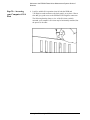
Step 2b - Accessing
your Computer’s ISA
Slots
6. Look for suitable ISA expansion slots for both the GPIB and
VXI-Digitizer cards and remove the back panel’s cover plates. Choose
slots that give good access to the GPIB and VXI-Digitizer connectors.
The following drawing shows a view of the ISA slots vertically
mounted; your computer’s ISA slots may be horizontally mounted, but
the process is the same.
1-8 Agilent Technologies E5500A Installation Guide
Welcome to the E5500A Phase Noise Measurement System Series of
Solutions
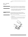
Step 2c - Taking ESD
Precautions
CAUTION
To prevent possible ESD damage, you must be properly grounded with a
grounding wrist strap before touching the VXI-Digitizer or GPIB Interface
Cards. While inserting the cards, be sure to hold the cards by their edges.
7. Using the disposable grounding strap, supplied with the VXI-Digitizer
interface card, unwrap the first two folds of the wrist strap and wrap the
exposed adhesive side firmly around your wrist.
CAUTION
Wear this grounding wrist strap before unpacking or touching the
VXI-Digitizer or GPIB interface cards; it is provided for control of static
electricity. Failure to use the grounding wrist strap properly can result in
damage to electronic devices and assemblies
8. Unroll the rest of the wrist strap and peel the liner from the copper foil at
the opposite end.
9. Attach the copper foil to a convenient and exposed electrical ground
somewhere on the computer’s chassis. This should be an unpainted
surface of the computer cabinet.
Agilent Technologies E5500A Installation Guide 1- 9
Welcome to the E5500A Phase Noise Measurement System Series of
Solutions
Step 2d- Installing the
Interface Cards
Installing the GPIB Interface Card
10. Verify that the GPIB (Agilent/HP 82341C GPIB) Interface card is set to
the following settings:
•
•
switches 1-2-3 set the base port address
❍
0-0-0: 0x250-0x257 (default)
switch 4 is not used
11. Insert the GPIB interface edge connector into the expansion slot
connector of the computer. Make sure the interface is fully seated by
pushing firmly on the edge of the card with the palm of your hand. The
GPIB connector should extend through the back panel opening to allow
cable installation.
NOTE
Use of a GPIB connector extender may be necessary for adequate clearance
between the GPIB cable and the computer chassis.
1-10 Agilent Technologies E5500A Installation Guide
12. Replace the GPIB back-panel cover plate screw to hold the interface in
place. (Save the blank cover plate for use if the interface is removed
later.
Installing the PCI-MIX-2 Digitizer Interface Card
13. Insert the PCI-MIX-2 Digitizer interface edge connector into the
expansion slot connector of the computer. Make sure the interface is
fully seated by pushing firmly on the edge of the card with the palm of
your hand.
14. Replace the PCI-MIX-2 Digitizer back-panel cover plate screw to hold
the interface in place. (Save the blank cover plate for use if the interface
is removed later.
Agilent Technologies E5500A Installation Guide 1-11
Welcome to the E5500A Phase Noise Measurement System Series of
Solutions
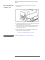
Step 2e - Replacing the
Computer Cover
15. Replace the computer cover as described in your computer’s
documentation.
16. Connect the double cable between the VXI-Digitizer PC interface card
and the Agilent/HP E1421B VXI mainframe.
17. Connect a BNC to BNC cable between the Agilent/HP E1430A VXI
card’s Analog in connector and the Agilent/HP 70420A Test Set’s
<100 MHz output connector.
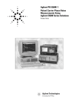
18. Refer to the following system connect diagram example for more
information about system interconnections:
❍
NOTE
“E5500A Connect Diagram Example” on page 1-13
For additional examples, refer to A, “Connect Diagrams”.
1-12 Agilent Technologies E5500A Installation Guide
Welcome to the E5500A Phase Noise Measurement System Series of
Solutions
E5500A Connect Diagram Example
Agilent Technologies E5500A Installation Guide 1- 13
Welcome to the E5500A Phase Noise Measurement System Series of
Solutions
Step 3. Installing the I/O Libraries
Installing the I/O libraries involves the following steps:
•
•
Step 3a - Installing the Agilent/HP I/O Libraries, page 1-14
Step 3b - Installing the Agilent/HP I/O Library Upgrade, page 1-15
NOTE
If, for any reason, the Agilent/HP I/O Libraries must be re-installed at a later
date, the E5500 Measurement Software (Step 6.) must also be re-installed
after the I/O Library installation.
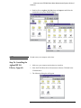
Step 3a - Installing the
Agilent/HP I/O
Libraries
1. Make sure your computer and monitor are turned on.
2. Place the E5500 Phase Noise Measurement Software CD-ROM in the
CD-ROM drive.
3. The following dialog box will appear.
1-14 Agilent Technologies E5500A Installation Guide
Welcome to the E5500A Phase Noise Measurement System Series of
Solutions
4. Double-click on Agilent_IO_Libs, then on Setup.exe and follow the
instructions (accept the default settings).
NOTE
Do not restart your computer at this time.
Step 3b - Installing the
Agilent/HP I/O
Library Upgrade
1. Make sure your computer and monitor are turned on.
2. Place the E5500 Phase Noise Measurement Software CD-ROM in the
CD-ROM drive.
3. The following dialog box will appear.
Agilent Technologies E5500A Installation Guide 1- 15
Welcome to the E5500A Phase Noise Measurement System Series of
Solutions
4. Double-click on Agilent_IO_libs, Upgrade_IO, then on Install.exe.
NOTE
Do not restart your computer at this time.
1-16 Agilent Technologies E5500A Installation Guide
Welcome to the E5500A Phase Noise Measurement System Series of
Solutions
Step 4. Installing the VXI-Digitizer Software
NOTE
If you have ordered a preconfigured phase noise system from Agilent
Technologies, skip this step and proceed to “Step 9. Starting the
Measurement Software” on page 1-35.
1. Make sure your computer and monitor are turned on.
2. Place the E5500 Phase Noise Measurement Software CD-ROM in the
CD-ROM drive.
3. The following dialog box will appear.
Agilent Technologies E5500A Installation Guide 1- 17
Welcome to the E5500A Phase Noise Measurement System Series of
Solutions
4. Double-click on NI_IO_Libs, Vxi, Disk 1, then on Setup.exe and
follow the instructions (accept the default settings).
NOTE
When offered the choice, do not restart your computer at this time.
1-18 Agilent Technologies E5500A Installation Guide
Welcome to the E5500A Phase Noise Measurement System Series of
Solutions
Step 5. Installing the Windows NT 4.0 Service
Pack
NOTE
If you have ordered a preconfigured phase noise system from Agilent
Technologies, skip this step and proceed to “Step 9. Starting the
Measurement Software” on page 1-35.
1. Make sure your computer and monitor are turned on.
2. Place the E5500 Phase Noise Measurement Software CD-ROM in the
CD-ROM drive.
3. The following dialog box will appear.
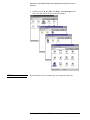
4. Double-click on Service Pack, then on Update, then on Update.exe and
follow the instructions (accept the default settings).
5. Reboot your computer at this time.
Agilent Technologies E5500A Installation Guide 1- 19
Welcome to the E5500A Phase Noise Measurement System Series of
Solutions
Step 6. Installing the Measurement Software
NOTE
If you have ordered a preconfigured phase noise system from Agilent
Technologies, skip this step and proceed to “Step 9. Starting the
Measurement Software” on page 1-35.
1. Make sure your computer and monitor are turned on.
2. Place the E5500 Phase Noise Measurement Software CD-ROM in the
CD-ROM drive.
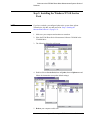
3. The following dialog box will appear. Double click on Setup.exe and
follow the instructions (accept the default settings).
1-20 Agilent Technologies E5500A Installation Guide
Welcome to the E5500A Phase Noise Measurement System Series of
Solutions
Step 7. Using the Asset Manager to Configure
your System
The following procedure will configure both the Agilent/HP 70420A Phase
Noise Test Set and VXI-Digitizer so they can be used in the E5500A Phase
Noise Measurement System to make measurements.
NOTE
If you have ordered a preconfigured phase noise system from Agilent
Technologies, skip this step and proceed to “Step 9. Starting the
Measurement Software” on page 1-35.
1. Make sure your computer and monitor are turned on.
2. Place the E5500 Phase Noise Measurement Software CD-ROM in the
CD-ROM drive.
3. Click the Start button, point to Programs, point to Agilent
Subsystems, point to E5500 Phase Noise, and then click E5500 Asset
Manager.
Agilent Technologies E5500A Installation Guide 1- 21
Welcome to the E5500A Phase Noise Measurement System Series of
Solutions
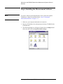
4. To place the Asset Manager in non-demo mode, click Options, and then
click Demo Mode to unselect Demo Mode.
5. Click OK. The Asset Manager can be invoked from within the phase
noise measurement software, and if that were the case you would need to
restart the software for any changes made in the Asset Manager to take
effect.
Configuring the
Agilent/HP 70420A
Test Set
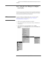
6. Click the Asset Wizard button to start configuring the
Agilent/HP 70420A Phase Noise Test Set using the Asset
Manager Asset Wizard.
1-22 Agilent Technologies E5500A Installation Guide
Welcome to the E5500A Phase Noise Measurement System Series of
Solutions
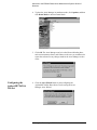
7. From the Asset Type pull-down list, select Test Set, then click the Next
button.
8. Click on Agilent/HP 70420, then click the Next button.
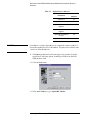
9. From the Interface pull-down list, select GPIB0.
10. In the Address box, type 20. 20 is the default address for the
Agilent/HP 70420A phase noise test set.
The following are default device addresses used by Agilent Technologies.
Table 1-3
Default Device Addresses
Instrument
Address
Agilent/HP 70420A Test Set
20
Agilent/HP 70421A
Downconverter
28
Agilent/HP 70422A
Downconverter
28
Agilent/HP 70427A
Downconverter
28
RF Analyzer
17
FFT Analyzer
18
Source # 1
19
Agilent Technologies E5500A Installation Guide 1- 23
Welcome to the E5500A Phase Noise Measurement System Series of
Solutions
Table 1-3
Default Device Addresses
Instrument
CAUTION
Address
Source # 2
23
Counter
3
Agilent/HP E1430 VXI
Digitizer
129
Agilent/HP E1437 VXI
Digitizer
192
Agilent/HP E1420B VXI
Counter
48
Agilent/HP E1441 VXI Arb
80
If an address is a single digit address, for example the counter at address 3,
do not add a leading zero (03) to the address. The phase noise software treats
3 and 03 as different addresses.
11. The Library pull-down list does not apply to this example. It applies
specifically to either the Agilent Technologies GPIB or the National
GPIB interface cards.
12. Click the Next button.
13. In the Asset Name box, type Agilent/HP 70420A.
1-24 Agilent Technologies E5500A Installation Guide
Welcome to the E5500A Phase Noise Measurement System Series of
Solutions
14. In the Serial Number (optional) box, type the serial number for your
Agilent/HP 70420A test set. Click the Next button.
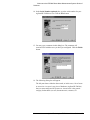
15. You may type a comment in this dialog box. The comment will
associate itself with the asset you have just configured. Click the Finish
button.
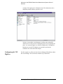
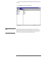
16. The following dialog box will appear.
The left pane shows either the demo mode, or in this case, a list of assets
or asset roles. An asset is any piece of hardware (Agilent/HP 70420A)
that you want configured for system use. An asset role is the general
category for hardware (test sets, downconverters, counters, for
Agilent Technologies E5500A Installation Guide 1- 25
Welcome to the E5500A Phase Noise Measurement System Series of
Solutions
example). The right pane is information only. The information can be
changed by double-clicking a specific asset.
You have just used the Asset Manager to configure the Agilent/HP
70420A test set. The process for configuring any asset is essentially the
same. As a second example, we will now configure the VXI-Digitizer.
Both the test set and VXI-digitizer are required to perform the
confidence test at the end of this chapter.
Configuring the VXI
Digitizer
For this example we will use invoke the Asset Manager Wizard from within
the Asset Manager. This is the most common way to add assets.
1-26 Agilent Technologies E5500A Installation Guide
Welcome to the E5500A Phase Noise Measurement System Series of
Solutions
17. Click Asset, and then click Add.
18. From the Asset Type pull-down list, select FFT Analyzer, then click
the Next button.
Agilent Technologies E5500A Installation Guide 1- 27
Welcome to the E5500A Phase Noise Measurement System Series of
Solutions
19. Click on Agilent/HP E1430A, then click the Next button
20. From the Interface pull-down list, select VXI0 via MXI.
21. In the Address box, type 129. 129 is the default address for the
Agilent/HP E1430 VXI-Digitizer.
1-28 Agilent Technologies E5500A Installation Guide
Welcome to the E5500A Phase Noise Measurement System Series of
Solutions
The following are default device addresses used by Agilent Technologies.
Table 1-4
Default Device Addresses
Instrument
CAUTION
Address
Agilent/HP 70420A Test Set
20
Agilent/HP 70422A
Downconverter
28
RF Analyzer
18
Source
19
Counter
3
Agilent/HP E1430 VXI
Digitizer
129
Agilent/HP E1420B VXI
Counter
48
Agilent/HP E1441A VXI Arb
80
If an address is a single digit address, for example the counter at address 3,
do not add a leading zero (03) to the address. The phase noise software treats
3 and 03 as different addresses.
22. In the Library pull-down list, select the National Instruments VISA
NOTE
All VXI devices require the National Instruments VISA library.
23. Click the Next button.
Agilent Technologies E5500A Installation Guide 1- 29
Welcome to the E5500A Phase Noise Measurement System Series of
Solutions
24. In the Asset Name box, type Agilent/HP E1430A.
25. In the Serial Number (optional) box, type the serial number for your
VXI-digitizer. Click the Next button.
26. From the Baseband Source pull-down list, select (none).
NOTE
If you had previously configured an Agilent/HP E1441A VXI Arb into the
Asset Manager for use as a baseband noise source for PLL loop suppression
verification, that option would also be available and you would select it here.
27. Click the Next button.
1-30 Agilent Technologies E5500A Installation Guide
Welcome to the E5500A Phase Noise Measurement System Series of
Solutions
28. You may type a comment in this dialog box. The comment will
associate itself with the asset you have just configured. Click the Finish
button.
29. You have just used the Asset Manager to configure the VXI-digitizer.
The process you have used to configure both the Agilent/HP 70420A
and VXI-digitizer is the same process you will use to add software
controlled assets to the phase noise measurement software.
30. Click Server, and then click Exit to exit the Asset Manager. Next we
will enter the license key for the software.
Agilent Technologies E5500A Installation Guide 1- 31
Welcome to the E5500A Phase Noise Measurement System Series of
Solutions
Step 8. Entering the License Key for the Phase
Noise Test Set
Use the following procedure to enter your keyword for your Agilent/HP
70420A Phase Noise Test Set.
NOTE
If you have ordered a preconfigured phase noise system from Agilent
Technologies, skip this step and proceed to “Step 9. Starting the
Measurement Software” on page 1-35.
1. Make sure your computer and monitor are turned on.
2. Click the Start button, point to Programs, point to Agilent
Subsystems, point to E5500 Phase Noise, and then click E5500 Asset
Manager.
1-32 Agilent Technologies E5500A Installation Guide
Welcome to the E5500A Phase Noise Measurement System Series of
Solutions
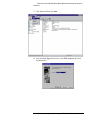
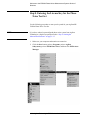
3. Click Options, and then click License Keys.
NOTE
The license key for your system is unique and may only be used with a
specific Agilent/HP 70420A Test Set serial number. The license key may be
found both on your license-key document and in the file “license_key.txt”
on the License_key floppy disk provided with your system.
Agilent Technologies E5500A Installation Guide 1- 33
Welcome to the E5500A Phase Noise Measurement System Series of
Solutions
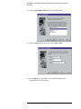
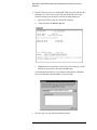
4. Enter the license key for your Agilent/HP 70420A Test Set and click the
Set button. Use the Licence_key.txt file described in the next step to
facilitate entering your license key into the licensing dialog box.
a. Insert the E5500 License Key disk in the computer.
b. Using Notepad, load License_key.txt.
c. Highlight the keyword in the License_key.txt file and copy it to the
dialog box shown below, then click the Set button.
For information about how to copy and paste information in Windows,
refer to the Windows documentation or On-Line Help.
5. The next step is to start the measurement software.
1-34 Agilent Technologies E5500A Installation Guide
Welcome to the E5500A Phase Noise Measurement System Series of
Solutions
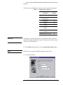
Step 9. Starting the Measurement Software
1. Click the Start button, point to Programs, point to Agilent
Subsystems, point to E5500 Phase Noise, and then click E5500 User
Interface.
2. The following dialog box appears.
Agilent Technologies E5500A Installation Guide 1- 35
Welcome to the E5500A Phase Noise Measurement System Series of
Solutions
Step 10. Using Server Hardware Connections to
Specify Assets for the Confidence Test
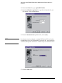
1. From the System menu, choose Server Hardware Connections.
2. The following dialog box will appear.
1-36 Agilent Technologies E5500A Installation Guide
Welcome to the E5500A Phase Noise Measurement System Series of
Solutions
3. From the Test Set pull-down list, select Agilent/HP 70420A. Click the
Check I/O button. A green check-mark will appear after the I/O check
has been performed by the software. If a red circle with a slash appears,
return to the Asset Manager (click the Asset Manager button) and
verify that the Agilent/HP 70420A and VXI-Digitizer are configured
correctly (check that the license key has been entered correctly). Also
check your system hardware connections. Click the Check I/O button
for a re-check.
4. From the FFT Analyzer pull-down list, select Agilent/HP E1430A.
Click the Check I/O button. A green check-mark will appear after the
I/O check has been performed by the software.
Selecting both the Agilent/HP 70420A test set and the Agilent/HP
E1430A FFT Analyzer (VXI digitizer) will tie both assets to the
confidence test we will be performing in the next step.
Agilent Technologies E5500A Installation Guide 1- 37
Welcome to the E5500A Phase Noise Measurement System Series of
Solutions
Step 11. Running the System Confidence Test
This measurement demonstration will introduce you to the system’s
operation by guiding you through an actual phase noise measurement.
This first measurement tests the Agilent/HP 70420A Test Set’s low-noise
amplifier circuitry. The phase detectors are not tested. This measurement
will also confirm that the PC and phase noise test set are communicating
with each other.
1. From the File menu, choose Open.
2. If necessary, choose the drive or directory where the file you want is
stored.
3. In the File Name box, choose Confidence.pnm.
4. Click the Open button.
1-38 Agilent Technologies E5500A Installation Guide
Welcome to the E5500A Phase Noise Measurement System Series of
Solutions
The appropriate measurement definition parameters for this example
have been pre-stored in this file. Table 1-5 on page 1-41 lists the
parameter data that has been entered for the Agilent/HP 70420A
Confidence Test example.
Beginning the
Measurement
1. From the Measure menu, choose New Measurement.
2. When the Perform a New Calibration and Measurement dialog box
appears, click OK.
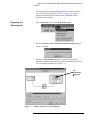
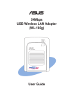
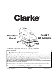
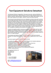
3. When the Connect Diagram dialog box appears, connect the 50 Ω
termination provided with your system to the Agilent/HP 70420A Test
Set’s Noise Input connector. (See Figure 1-1.)
50 Ω
termination
goes here
Figure 1-1
System Confidence Test Setup Diagram.
Agilent Technologies E5500A Installation Guide 1- 39
Welcome to the E5500A Phase Noise Measurement System Series of
Solutions
Making the
Measurement
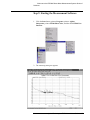
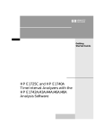
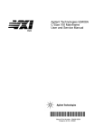
1. Press the Continue key. Because you selected New Measurement to
begin this measurement, the System starts by running the routines
required to calibrate the current measurement setup.
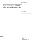
Figure 1-2 shows a typical baseband phase noise plot for an Agilent/HP
70420A Phase Noise Test Set.
Figure 1-2
Congratulations
Typical Phase Noise Curve for a System Confidence Test.
You have completed a phase noise measurement. You will find that this
measurement of the Agilent/HP 70420A Phase Noise Test Set’s low-noise
amplifier circuitry provides a convenient way to verify that the System
hardware and software are properly configured for making noise
measurements.
1-40 Agilent Technologies E5500A Installation Guide
Welcome to the E5500A Phase Noise Measurement System Series of
Solutions
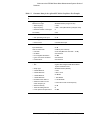
Table 1-5
Parameter Data for the Agilent/HP 70420A Confidence Test Example
Ste
p
Parameters
1
Type and Range Tab
2
Data
Measurement Type
• Baseband Noise (using a test set)
• Start Frequency
• 10 Hz
• Stop Frequency
• 100E + 6 Hz (determined by analyzer used)
• Minimum Number of Averages
• 4
FFT Quality
• Fast
Cal Tab
• Gain preceding noise input
3
Block Diagram Tab
• Noise Source
4
5
• 0 dB
• Test Set Noise Input
Test Set Tab
Input Attenuation
• 0 dB
LNA Low Pass Filter
• 20 MHz (Auto checked)
• LNA Gain
• Auto Gain (Minimum Auto Gain - 14 dB)
• DC Block
• Not checked
• PLL Integrator Attenuation
• 0 dBm
• Ignore out-of-lock conditions
• Not checked
• Pulsed Carrier
• Not checked
Graph Tab
• Title
• Agilent Technologies E5500 Phase Noise
System Confidence Test
• Graph Type
• Baseband Noise (dBV/Hz)
• X Scale Minimum
• 10 Hz
• X Scale Maximum
• 100 E + 6 Hz
• Y Scale Minimum
• 0 dBc/Hz
• Y Scale Maximum
• - 200 dBc/Hz
• Normalize trace data to a
• 1 Hz bandwidth
• Scale trace data to a new
carrier frequency of
• 1 times the current carrier frequency
• Shift trace data by
• 0 dB
• Trace Smoothing Amount
• 0
• Power present at input of DUT
• 0 dBm
Agilent Technologies E5500A Installation Guide 1- 41
A
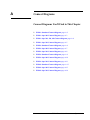
Connect Diagrams
Connect Diagrams You’ll Find in This Chapter
•
•
•
•
•
•
•
•
•
•
•
•
•
E5501A Standard Connect Diagram, page A-2
E5501A Opt. 001 Connect Diagram, page A-3
E5501A Opt. 201, 430, 440 Connect Diagram, page A-4
E5501A Opt. 201 Connect Diagram, page A-5
E5502A Standard Connect Diagram, page A-6
E5502A Opt. 001 Connect Diagram, page A-7
E5502A Opt. 201 Connect Diagram, page A-8
E5503A Standard Connect Diagram, page A-9
E5503A Opt. 001 Connect Diagram, page A-10
E5503A Opt. 201 Connect Diagram, page A-11
E5504A Standard Connect Diagram, page A-12
E5504A Opt. 001 Connect Diagram, page A-13
E5504A Opt. 201 Connect Diagram, page A-14
E5500 Phase Noise Measurement System A-1
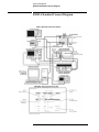
Connect Diagrams
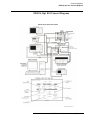
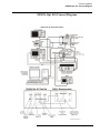
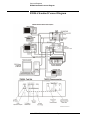
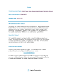
E5501A Standard Connect Diagram
E5501A Standard Connect Diagram
A-2 E5500 Phase Noise Measurement System
Connect Diagrams
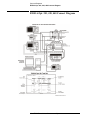
E5501A Opt. 001 Connect Diagram
E5501A Opt. 001 Connect Diagram
E5500 Phase Noise Measurement System A- 3
Connect Diagrams
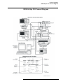
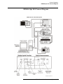
E5501A Opt. 201, 430, 440 Connect Diagram
E5501A Opt. 201, 430, 440 Connect Diagram
A-4 E5500 Phase Noise Measurement System
Connect Diagrams
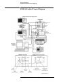
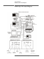
E5501A Opt. 201 Connect Diagram
E5501A Opt. 201 Connect Diagram
E5500 Phase Noise Measurement System A- 5
Connect Diagrams
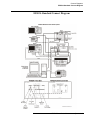
E5502A Standard Connect Diagram
E5502A Standard Connect Diagram
A-6 E5500 Phase Noise Measurement System
Connect Diagrams
E5502A Opt. 001 Connect Diagram
E5502A Opt. 001 Connect Diagram
E5500 Phase Noise Measurement System A- 7
Connect Diagrams
E5502A Opt. 201 Connect Diagram
E5502A Opt. 201 Connect Diagram
A-8 E5500 Phase Noise Measurement System
Connect Diagrams
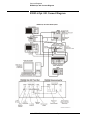
E5503A Standard Connect Diagram
E5503A Standard Connect Diagram
E5500 Phase Noise Measurement System A- 9
Connect Diagrams
E5503A Opt. 001 Connect Diagram
E5503A Opt. 001 Connect Diagram
A-10 E5500 Phase Noise Measurement System
E5503A Opt. 201 Connect Diagram
E5500 Phase Noise Measurement System A-11
Connect Diagrams
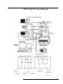
E5504A Standard Connect Diagram
E5504A Standard Connect Diagram
A-12 E5500 Phase Noise Measurement System
Connect Diagrams
E5504A Opt. 001 Connect Diagram
E5504A Opt. 001 Connect Diagram
E5500 Phase Noise Measurement System A- 13
Connect Diagrams
E5504A Opt. 201 Connect Diagram
E5504A Opt. 201 Connect Diagram
A-14 E5500 Phase Noise Measurement System
Index
Index
L
license key
entering, 1-32
A
accessing your computer’s ISA slots, 1-8
Asset Manager
Configuring your System, 1-21
C
computer cover
replacing, 1-12
configuring your system
asset manager, 1-21
connections
using server hardware, 1-36
cover
removing computer’s, 1-7
E
entering the license key, 1-32
ESD precautions, 1-9
H
hardware
installing, 1-6
I
I/O libraries
installing, 1-14
installation steps, 1-3
installing the Agilent/HP I/O library upgrade, 1-15
installing the hardware, 1-6
installing the I/O libraries, 1-14
installing the interface cards, 1-10
installing the measurement software, 1-20
installing the VXI-Digitizer software, 1-17
installing the Windows NT 4.0 Service Pack, 1-19
interface cards
installing, 1-10
ISA slots
accessing, 1-8
M
measurement software
installing, 1-20
starting, 1-35
P
precautions
ESD, 1-9
R
removing your computer’s cover, 1-7
replacing the computer cover, 1-12
requirements
system, 1-4
S
starting the measurement software, 1-35
steps
installation, 1-3
system
confidence test, 1-38
unpacking, 1-5
system confidence test, 1-38
system requirements, 1-4
U
unpacking your system, 1-5
upgrade
Agilent/HP I/O library, 1-15
using server hardware connections, 1-36
using this guide, 1-20
V
VXI-Digitizer software
installing, 1-17
Agilent Technologies E5500A Installation Guide Index-1
Index
W
Windows NT 4.0 Service Pack
installing, 1-19
Index-2 Agilent Technologies E5500A Installation Guide