1
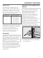
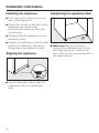
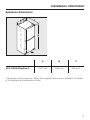
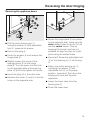
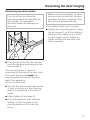
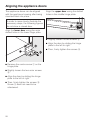
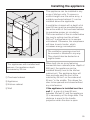
Installation Instructions KFN12823 SD en - CA Installation, repair and maintenance work should be performed by a Miele authorized service technician in accordance with national and local safety regulations and the provided installation instructions. Electrical connection ,Failure to follow these instructions can result in death, fire, or electrical shock. Improper connection of the equipment grounding conductor may result in electric shock. If you are in any doubt as to whether the appliance has been properly grounded, have the appliance checked by a qualified electrician or service technician. Installation, repairs and other work by unqualified persons could be dangerous. The manufacturer will not be held responsible for damage or injury arising from unauthorized work. Before installing the appliance, verify that the voltage, load and circuit rating information found on the data plate match the household electrical supply. ,Do not ground to a gas pipe. Check with a qualified elictrician if you are not sure the appliance is properly grounded. Do not have a fuse in the neutral or grounding curcuit. ,Electrocution hazard Electrical grounding required. This appliance is equipped with a three-prong (grounding) polarized plug for your protection against possible shock hazards. Do not remove the round grounding prong from the plug. Do not use a two-prong grounding adapter. Do not use extension cords or ungrounded (two prong) adapters. Connect this appliance to a 110 – 120 VAC, 60 Hz and 15 amp (20 amp for side-by-side) circuit (20 amp for side-by-side) with a circuit breaker or fuse. This appliance should have its own separate grounded circuit. The power cord is equipped with a three-prong (grounding) plug for your protection against potential electrical shock. To maintain this protection: – Do not modify the plug by removing the round grounding prong. – Do not use a two-prong adapter. Where a two-prong wall outlet is encountered, contact a qualified electrician and have it replaced with a three-prong outlet in accordance with the local electrical codes and regulations. – Do not use a power cord that is frayed or damaged. – Do not connect the appliance using an extension cord or extension socket. 46 Electrical connection The appliance must be connected to an electrical outlet that is properly grounded. The electrical installation must comply with the applicable electrical code. The outlet must be easily accessible and not concealed behind the appliance so that the appliance can quickly be disconnected from the electricity supply in an emergency. The plug and power cable must not come into contact with the back of the appliance, as they could be damaged by vibrations from the appliance. This may result in a short circuit. In addition, no other appliances should be plugged into a socket located directly behind this appliance. Do not use an extension cord to connect the appliance to the power supply. Extension cords do not guarantee the required safety of the appliance (e.g. they pose a danger of overheating). Do not connect the appliance to stand-alone inverters, such as those used with an autonomous energy source, e.g. solar power systems. Otherwise, when the appliance is switched on, peak loads in the system can cause the safety shutdown mechanism to be triggered. This can damage electronic units. In addition, the appliance must not be used with energy-saving devices, which reduce the amount of energy supplied to the appliance and cause it to overheat. If the power cable needs to be replaced, this work must only be performed by a qualified electrician. 47 Installation information Location Safe operation of the appliance is only assured if it has been installed and connected in accordance with these operating and installation instructions. WARNING! Danger of tilting! To avoid a hazard due to instability of the appliance, it must be fixde in accordance with the instructions. Do not use any appliances which give off heat, such as toaster ovens, portable burners or toasters, on the the appliance. The appliance may catch fire. Fire hazard! This fridge/freezer combination should not be installed directly next to a second model (in a side-by-side position). Because the appliance does not have heated side walls, a side-by-side installation can result in the accumulation of condensation. Contact your dealer for more information. 48 This appliance should not be installed near windows where it is exposed to direct sunlight or directly adjacent to heat-producing appliances such as an oven or a radiator. The higher the room temperature, the longer the compressor runs, increasing energy consumption by the appliance. Install the appliance in a dry, well-ventilated room. The following should also be taken into consideration: – The power outlet must not be located directly behind the appliance and must be easily accessible in an emergency. – The plug and power cable must not touch the back of the appliance, as they could be damaged by vibrations from the appliance. – No other appliances should be plugged into a socket located directly behind this appliance. Important! In environments with high humidity condensation can build up on the appliance exterior and ultimately cause corrosion on the outer walls. To prevent this from happening, we recommend installing the appliance in a dry and/or an air-conditioned room with sufficient ventilation. Once you have completed the installation, please make sure that the appliance doors close properly, that the ventilation openings are not covered and that the appliance has been installed as described in this chapter. Installation information Climate class The appliance is designed for use within a certain climate class (room temperature range) and should not be used outside this range. The climate class for your appliance is stated on the data plate inside the appliance. Climate class Room temperature SN +10 °C à +32 °C (50 °F à 90 °F) +16 °C à +32 °C (61 °F à 90 °F) +16 °C à +38 °C (61 °F à 100 °F) +16 °C à +43 °C (61 °F à 109 °F) N ST T Operating in a room which is too cold will cause the compressor to switch off for too long. This may result in increased temperatures inside the appliance, which can even cause frozen food to being thawing. Appliances with supplied wall spacers To achieve the indicated level of energy consumption, you should use the wall spacers that are included with a number of appliances. When installed, wall spacers increase the appliance depth by approx. 35 mm. If you elect not to use the wall spacers, your decision will have no impact on the functioning of the appliance. However, the smaller distance to the wall means that there will be a slight increase in this appliance's energy consumption. Ventilation WARNING! Danger of damage from overheating. May restrict operation. Keep ventilation openings, in the appliance enclosure or in the built-in structure, clear of obstruction. ^ Install the wall spacers in the top leftand right-hand corners on the back of the appliance. Air at the back of the appliance gets warm. To ensure proper ventilation, make sure that the ventilation openings are not covered or blocked in any way. They should also be dusted on a regular basis. 49 Installation information Installing the appliance Supporting the appliance door ^ First, remove the cable clip from the back of the appliance. ^ Check that all parts at the back of the appliance can vibrate freely. Carefully bend apart any parts that are touching. ^ Carefully slide the appliance into the desired location. ^ Position the appliance so that the wall spacers (if installed) or the back of the appliance are against the wall. Aligning the appliance ^ Use the adjustable feet to align the appliance so that it is stable and level. 50 ^ Make sure that you continue to unscrew the adjustable foot a from the hinge plate until it rests on the floor. Then turn the foot another 90° in the same direction. Installation information Appliance dimensions KFN 12823 SD edt/cs-2 A B C 1817 mm 600 mm 630 mm* * Dimension without spacers. When the supplied spacers are installed, the depth of the appliance increases by 35 mm. 51 Reversing the door hinging The appliance is delivered with right-hand door hinging. If left-hand hinging is required, the door hinging must be reversed: Removing the door handles: To reverse the door hinging, you will need the following tools: When reversing the door hinging, always enlist the help of another person. ^ When you pull the door handle a, the sidebar b slides back. ^ Remove the sidebar b from the guide by firmly pulling towards the appliance. ^ Now loosen the four screws (TX15) in the mounting plate and remove the handle. ^ Remove the cover caps from the opposite side, and fit them into the empty holes. 52 Reversing the door hinging Removing the appliance doors: Remove all food and drink from the door shelves on the inside of the doors. the left and pulling the cover forwards. ^ Turn the retaining plate f 180°. ^ Fit cover e onto the front of the retaining plate f and slide the cover to the right. The writing must be visible. ^ Remove cover g, turn it 180° and snap it into place on the opposite side. ^ Snap cover e and the retaining plate f into place on the opposite side. ^ Close the upper door. ^ Remove cover a by sliding it forwards and lifting it off. ^ Remove cover b by pulling it upwards. Caution! The upper door is no longer secured in place once the hinge plate has been removed in the next step. ^ Loosen the screws d on the upper hinge plate c and lift the hinge plate upwards to remove. ^ Carefully lift the upper door off of the appliance and set it aside. ^ Using a screwdriver, carefully loosen the cover e from above and remove it together with the retaining plate f. ^ Separate the retaining plate f from the cover e by sliding it slightly to 53 Reversing the door hinging ^ Close the lower door. Caution! The lower door is no longer secured in place once the hinge plate has been removed in the next step. ^ Remove the middle bearing pin i by pulling it upwards. ^ Lift each of the plugs l out of the door bushings and reinsert them on the opposite side. ^ Carefully lift the lower door off of the appliance and set it aside. ^ Pull off the cover j. ^ Unscrew the hinge plate k, turn it 180° and screw it into place on the opposite side. ^ Pull off the plastic cap h, turn it over and fit it back onto the hinge platek. ^ Attach the cover j on the opposite side. 54 ^ Using a screwdriver, remove each of the spring clips m from the bottom of the door and fit them on the opposite side. Reversing the door hinging Reversing the appliance doors: ^ Pull the entire bearing pin a, including washer b and adjustable foot c, upwards to remove. ^ Pull out the plug d. ^ Undo the screws e and remove the hinge plate f. ^ Slightly loosen the screw of the bearing piece h on the hinge platef. Turn the piece into the hole on the opposite side of the bearing plate f and firmly tighten the screw. ^ Insert the plug d in the other hole. ^ Remove the cover g and fit it into the holes on the opposite side. ^ Screw the hinge plate f into place on the opposite side, using only the outer slotted holes to do so. Do not use the centre screw. Only by keeping the centre hole free is it possible to align the door at a later point using the slotted holes. ^ Important! Screw the adjustable foot c on the bearing pin a all the way in. ^ Return the entire bearing pin a, including the washer b and adjustable foot c, to its proper position. Important! The tab on the bearing pin must still face the appliance. ^ Lower the lower door onto the bearing pin b. ^ Close the lower door. 55 Reversing the door hinging ^ Switch the positions of the covers a and b. ^ Align the door with the appliance housing using the slotted holes in the lower hinge plate. Then firmly tighten the screws. ^ Slide the bearing pin i through the middle hinge plate k and into the lower door. The pivot on the bearing pin rests in the notch on the hinge plate. ^ Place the upper door onto the bearing pin i at the middle of the appliance. ^ Close the upper door. ^ Position the hinge plate c on the opposite side and affix it using the screws d. You may have to pre-punch the necessary screw holes or use a battery-powered screwdriver. 56 Reversing the door hinging Reattaching the door handles: It is critical that you follow the instructions below for attaching the door handle. An improperly mounted handle will damage the door seal. Make sure that the sidebar d does not come into contact with the door seal when the door is opened. Over time, this will damage the seal. If the sidebar does touch the seal: ^ Realign the mounting plate c using the set screws a until the mounting plate and the sidebar d are at the correct angle and the sidebar no longer touches the seal when the door is opened. ^ First, loosely screw the door handle onto the opposite side using the two front screws b. The mounting plate c must be positioned on the side of the door such that, when the door is closed, the mounting plate is flush with the side wall of the appliance. If this is not the case, ^ Turn the two pre-mounted set screws a with a hex key until the mounting platec is positioned at the correct angle. ^ Firmly tighten all 4 screws b. ^ From the appliance side, slide the sidebar d into the guide on the mounting plate until it clicks into place. 57 Aligning the appliance doors The appliance doors can be aligned with the appliance housing after being mounted back into place. Align the upper door using the slotted holes in the middle hinge plate: In order to more clearly illustrate the necessary steps, the following figures do not show a closed door. Align the lower door using the outer slotted holes in the lower hinge plate: ^ Slightly loosen the two screws c. ^ Align the door by sliding the hinge plate to the left or right. ^ Then, firmly tighten the screws c. ^ Remove the centre screw a on the hinge plate. ^ Slightly loosen the two outer screws b. ^ Align the door by sliding the hinge plate to the left or right. ^ Then, firmly tighten the screws b. Screw a does not need to be refastened. 58 Installing the appliance This appliance can be installed in any array of kitchen units. To ensure a uniform height over the entire array, a suitable overhead cabinet a can be installed above the appliance. A ventilation channel with a depth of at least 50 mm must be provided across the entire width of the overhead cabinet to guarantee proper air circulation. The cross section of the air outlet below the room's ceiling must be at least 300 cm2 to allow warm air to escape unhindered. Otherwise, the compressor will have to work harder, which increases energy consumption. The ventilation openings must not be covered or blocked in any way. They should also be dusted on a regular basis. * For appliances with installed wall spacers, the appliance depth increases by 35 mm. a Overhead cabinet b Appliance c Kitchen cabinet d Wall When built into an array featuring normed kitchen cabinets (max. depth of 580 mm), the appliance can be installed directly next to the kitchen cabinet unit. The appliance door will then protrude past the front of the cabinet by 34 mm* on the sides and 55 mm* in the middle. This allows the door to be opened and closed without any interference. If the appliance is installed next to a wall d, a gap of at least 55 mm between the wall d and the appliance b is necessary on the hinge side. This distance is equal to the handle projection when the door is open. 59 60 61 62 &DQDGD ,PSRUWHU 0LHOH/LPLWHG +HDGTXDUWHUVDQG0LHOH&HQWUH &OUR6ALLEY$RIVE 6AUGHAN/.,+6 WWWMIELECA &XVWRPHU&DUH&HQWUH 0HONE CUSTOMERCARE MIELECA *HUPDQ\ 0DQXIDFWXUHU -IELE#IE+' #ARL-IELE3TRAE 'àTERSLOH 63 KFN 12823 SD edt/cs-2 en - CA M.-Nr. 09 852 800 / 00