1
SERVICE MANUAL
Serial Impact Dot Matrix Printer
EPSON FX-890/2190
®
SEDM02003
Notice
All rights reserved. No part of this manual may be reproduced, stored in a retrieval system, or transmitted in any form or by any means electronic,
mechanical, photocopying, or otherwise, without the prior written permission of SEIKO EPSON CORPORATION.
All effort have been made to ensure the accuracy of the contents of this manual. However, should any errors be detected, SEIKO EPSON would
greatly appreciate being informed of them.
The contents of this manual are subject to change without notice.
The above not withstanding SEIKO EPSON CORPORATION can assume no responsibility for any errors in this manual or the consequences
thereof.
EPSON is a registered trademark of SEIKO EPSON CORPORATION.
General Notice:
Other product names used herein are for identification purpose only and may be trademarks or registered trademarks of their
respective owners. EPSON disclaims any and all rights in those marks.
Copyright © 2003 SEIKO EPSON CORPORATION.
Imaging & Information Product Division
TPCS Quality Assurance Department
PRECAUTIONS
Precautionary notations throughout the text are categorized relative to 1)Personal injury and 2) damage to equipment.
DANGER
Signals a precaution which, if ignored, could result in serious or fatal personal injury. Great caution should be exercised in
performing procedures preceded by DANGER Headings.
WARNING
Signals a precaution which, if ignored, could result in damage to equipment.
The precautionary measures itemized below should always be observed when performing repair/maintenance procedures.
DANGER
1.
ALWAYS DISCONNECT THE PRODUCT FROM THE POWER SOURCE AND PERIPHERAL DEVICES PERFORMING ANY MAINTENANCE OR REPAIR
PROCEDURES.
2.
NO WORK SHOULD BE PERFORMED ON THE UNIT BY PERSONS UNFAMILIAR WITH BASIC SAFETY MEASURES AS DICTATED FOR ALL ELECTRONICS
TECHNICIANS IN THEIR LINE OF WORK.
3.
WHEN PERFORMING TESTING AS DICTATED WITHIN THIS MANUAL, DO NOT CONNECT THE UNIT TO A POWER SOURCE UNTIL INSTRUCTED TO DO
SO. WHEN THE POWER SUPPLY CABLE MUST BE CONNECTED, USE EXTREME CAUTION IN WORKING ON POWER SUPPLY AND OTHER ELECTRONIC
COMPONENTS.
4. When disassembling or assembling a product, be sure to wear gloves to avoid injuries from metal parts with sharp edges.
WARNING
1.
REPAIRS ON EPSON PRODUCT SHOULD BE PERFORMED ONLY BY AN EPSON CERTIFIED REPAIR TECHNICIAN.
2.
MAKE CERTAIN THAT THE SOURCE VOLTAGES IS THE SAME AS THE RATED VOLTAGE, LISTED ON THE SERIAL NUMBER/RATING PLATE. IF THE
EPSON PRODUCT HAS A PRIMARY AC RATING DIFFERENT FROM AVAILABLE POWER SOURCE, DO NOT CONNECT IT TO THE POWER SOURCE.
3.
ALWAYS VERIFY THAT THE EPSON PRODUCT HAS BEEN DISCONNECTED FROM THE POWER SOURCE BEFORE REMOVING OR REPLACING
PRINTED CIRCUIT BOARDS AND/OR INDIVIDUAL CHIPS.
4.
IN ORDER TO PROTECT SENSITIVE MICROPROCESSORS AND CIRCUITRY, USE STATIC DISCHARGE EQUIPMENT, SUCH AS ANTI-STATIC WRIST
STRAPS, WHEN ACCESSING INTERNAL COMPONENTS.
5.
DO NOT REPLACE IMPERFECTLY FUNCTIONING COMPONENTS WITH COMPONENTS WHICH ARE NOT MANUFACTURED BY EPSON. IF SECOND
SOURCE IF’S OR OTHER COMPONENTS WHICH HAVE NOT BEEN APPROVED ARE USED, THEY COULD CAUSE DAMAGE TO THE EPSON PRODUCT,
OR COULD VOID THE WARRANTY OFFERED BY EPSON.
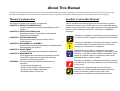
About This Manual
This manual describes basic functions, theory of electrical and mechanical operations, maintenance and repair procedures of the printer. The instructions and
procedures included herein are intended for the experienced repair technicians, and attention should be given to the precautions on the preceding page.
Manual Configuration
Symbols Used in this Manual
This manual consists of six chapters and Appendix.
CHAPTER 1. PRODUCT DESCRIPTIONS
Provides a general overview and specifications of the
product.
CHAPTER 2. OPERATING PRINCIPLES
Describes the theory of electrical and mechanical
operations of the product.
CHAPTER 3. TROUBLESHOOTING
Describes the step-by-step procedures for the
troubleshooting.
CHAPTER 4. DISASSEMBLY / ASSEMBLY
Describes the step-by-step procedures for disassembling
and assembling the product.
CHAPTER 5. ADJUSTMENT
Provides Epson-approved methods for adjustment.
CHAPTER 6. MAINTENANCE
Provides preventive maintenance procedures and the
lists of Epson-approved lubricants and adhesives
required for servicing the product.
APPENDIX Provides the following additional information for
reference:
• Connector pin assignments
• Electric circuit boards components layout
• Electrical circuit boards schematics
• Exploded diagram & Parts List
Various symbols are used throughout this manual either to provide
additional information on a specific topic or to warn of possible danger
present during a procedure or an action. Be aware of all symbols when
they are used, and always read NOTE, CAUTION, or WARNING
messages.
A D J U S T M E N T
R E Q U IR E D
C A U T IO N
C H E C K
P O IN T
W A R N IN G
Indicates an operating or maintenance procedure, practice
or condition that is necessary to keep the product’s quality.
Indicates an operating or maintenance procedure, practice,
or condition that, if not strictly observed, could result in
damage to, or destruction of, equipment.
May indicate an operating or maintenance procedure,
practice or condition that is necessary to accomplish a task
efficiently. It may also provide additional information that is
related to a specific subject, or comment on the results
achieved through a previous action.
Indicates an operating or maintenance procedure, practice
or condition that, if not strictly observed, could result in injury
or loss of life.
Indicates that a particular task must be carried out
according to a certain standard after disassembly and
before re-assembly, otherwise the quality of the
components in question may be adversely affected.
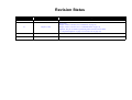
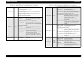
Revision Status
Revision
Date of Issue
A
June 20, 2003
B
August 21, 2003
Description
Formal first release
Revision up:
Chapter-3: Error Correction ("3.2.12 Fatal Error" on page 63)
Chapter-4: Error Correction ("4.2.3 C524MAIN Board" on page 74)
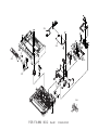
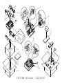
Appendix: The part list and the exploded diagram for the FX-2190 are added.
("7.3 Exploded Diagrams" on page 114, "7.4 Parts List" on page 122)
EPSON FX-890/2190
Revision B
Table of Contents
Chapter 1 PRODUCT DESCRIPTIONS
Chapter 2 Operating Principles
1.1 Features ............................................................................................................... 9
1.2 Interface .............................................................................................................
1.2.1 Parallel interface (Forward channel) ........................................................
1.2.2 Parallel interface (Reverse channel) .........................................................
1.2.3 USB Interface ...........................................................................................
1.2.4 Optional Interface .....................................................................................
1.2.5 Type-B Interface communication specification ........................................
1.2.6 Interface selection .....................................................................................
1.2.7 IEEE1284.4 protocol ................................................................................
23
23
25
26
27
27
28
29
1.3 Operation ...........................................................................................................
1.3.1 Control panel ............................................................................................
1.3.2 Switches ....................................................................................................
1.3.2.1 Operation in Normal Mode ...............................................................
1.3.2.2 Operations at Power-on .....................................................................
1.3.2.3 Operation in Default Setting Mode ...................................................
1.3.3 Indicators ( LEDs ) ...................................................................................
1.3.3.1 Indications in Normal Mode ..............................................................
1.3.4 Buzzer .......................................................................................................
1.3.5 Default Setting ..........................................................................................
1.3.5.1 Setting Method ..................................................................................
1.3.5.2 Setting Items ......................................................................................
1.3.6 EEPROM Clear Function .........................................................................
1.3.7 Bi-D Adjustment .......................................................................................
30
30
30
30
31
31
31
31
33
33
33
34
35
36
1.4 Dimensions and Weight ...................................................................................
1.4.1 FX-880T+ Mode .......................................................................................
1.4.1.1 Setting of FX-880T+ mode ...............................................................
1.4.1.2 Supported commands ........................................................................
1.4.1.3 Default setting items ..........................................................................
1.4.1.4 Printer defaults ..................................................................................
1.4.1.5 Action of the printer ..........................................................................
37
41
41
41
42
42
42
2.1 Overview ............................................................................................................
2.1.1 Printer Mechanism ....................................................................................
2.1.1.1 Printhead ............................................................................................
2.1.1.2 Paper Feed Mechanism .....................................................................
2.1.1.3 Carriage Movement Mechanism .......................................................
2.1.1.4 Tractor Feed Mechanism ...................................................................
2.1.1.5 Platen Gap Adjustment Mechanism ..................................................
2.1.1.6 Ribbon Feed Mechanism ...................................................................
2.1.1.7 Sensors ..............................................................................................
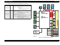
2.1.2 Circuit Operation ......................................................................................
2.1.2.1 C524 MAIN Board ............................................................................
2.1.2.2 C524 PSB/PSE/PSH Power Supply Circuit ......................................
44
45
45
45
45
45
45
46
46
47
47
50
Chapter 3 Troubleshooting
3.1 Overview ............................................................................................................
3.1.1 Specified Tools .........................................................................................
3.1.2 Procedure for Troubleshooting .................................................................
3.1.3 Preliminary Checks ...................................................................................
3.1.4 Error ..........................................................................................................
53
53
53
54
54
3.2 Troubleshooting Based on Symptoms ............................................................
3.2.1 Printer fails to operate when power is turned on ......................................
3.2.2 No LED on Control Panel lights up even with power turned on ..............
3.2.3 Abnormal operation of Carriage at power on ...........................................
3.2.4 Abnormal paper feeding ...........................................................................
3.2.5 Printing is faulty during self-test, but carriage operation is normal .........
3.2.6 Abnormal operation of Control Panel ......................................................
3.2.7 Abnormal on-line operation (normal self-printing, though) .....................
3.2.8 Abnormal operation of ribbon ..................................................................
3.2.9 Abnormal operation of Carriage Unit .......................................................
3.2.10 Faulty print .............................................................................................
55
55
56
56
57
58
59
59
60
61
62
6
EPSON FX-890/2190
Revision B
3.2.11 Electrical Noise ....................................................................................... 62
3.2.12 Fatal Error ............................................................................................... 63
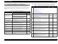
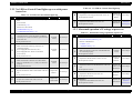
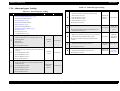
3.3 Troubleshooting for Individual Units ............................................................. 64
3.3.1 Main Component Checking Point ............................................................ 64
Chapter 4 Disassembly and Assembly
4.1 Overview ............................................................................................................
4.1.1 Disassembly Precautions ..........................................................................
4.1.2 Tools and Instruments ...............................................................................
4.1.3 Service Check After Repair ......................................................................
4.1.3.1 Abbreviations for Small Parts ...........................................................
66
66
66
67
68
4.2 Main Components Disassembly ......................................................................
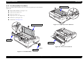
4.2.1 Pre-disassembly Procedures .....................................................................
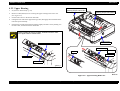
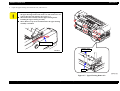
4.2.2 Upper Housing ..........................................................................................
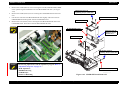
4.2.3 C524MAIN Board ....................................................................................
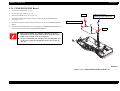
4.2.4 C524PSB/PSE/PSH Board .......................................................................
69
70
72
74
76
4.3 Printer Mechanism Disassembly .....................................................................
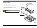
4.3.1 Printhead ...................................................................................................
4.3.2 HP (Home Position) Detector ...................................................................
4.3.3 Platen ........................................................................................................
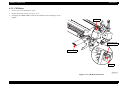
4.3.4 Printer Mechanism ....................................................................................
4.3.5 CR Motor ..................................................................................................
4.3.6 PF Motor ...................................................................................................
4.3.7 PF Gear Train ...........................................................................................
4.3.8 PG (Platen Gap) Detector .........................................................................
4.3.9 Release Detector .......................................................................................
4.3.10 Front PE (Paper End) Detector ...............................................................
4.3.11 Rear PE Detector ....................................................................................
4.3.12 Carriage Assembly ..................................................................................
4.3.13 Rear Paper Guide Assembly ...................................................................
4.3.14 Ribbon Drive (RD) Assembly ................................................................
77
77
78
79
80
81
83
84
86
86
87
87
88
90
92
5.2.1 Platen Gap Adjustment ............................................................................. 95
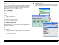
5.3 Adjustment Program .......................................................................................
5.3.1 Preparation ................................................................................................
5.3.1.1 System Requirement .........................................................................
5.3.1.2 Installation .........................................................................................
5.3.1.3 Running the Program ........................................................................
97
97
97
97
97
Chapter 6 Maintenance
6.1 Overview ............................................................................................................ 99
6.1.1 Preventive Maintenance ........................................................................... 99
6.2 Lubrication ...................................................................................................... 100
Chapter 7 Appendix
7.1 Connector Summary ...................................................................................... 105
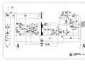
7.2 Electric Circuit Diagrams .............................................................................. 108
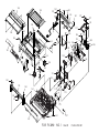
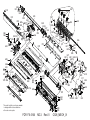
7.3 Exploded Diagrams ........................................................................................ 114
7.4 Parts List ......................................................................................................... 122
Chapter 5 Adjustment
5.1 Adjustment Overview ...................................................................................... 94
5.1.1 Required Adjustment ................................................................................ 94
5.1.2 Adjustment Tools ...................................................................................... 94
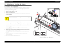
5.2 Adjusting and Resetting the Printer ............................................................... 95
7
1
CHAPTER
PRODUCT DESCRIPTIONS
EPSON FX-890/2190
Revision B
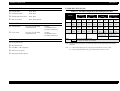
1.1 Features
PRINTING SPEED
EPSON FX-890/2190 is a small-foot 18-pin serial impact dot matrix printer.
Table 1-2. Printing Speed (cps) and Printable Columns
HARDWARE SPECIFICATIONS
Print method
: Impact Dot Matrix
Number of pins
Printing Mode
Character
Pitch
Printable Columns
FX-890
FX-2190
Printing Speed
Normal
Copy
10 cpi
80
136
566
489
: 18 pins
12 cpi
96
163
680
571
Print pin arrangement
: 9 pins x 2 files
10 cpi
80
136
559
476
Print pin diameter
: 0.29 mm (0.0114 inch)
12 cpi
96
163
627
539
Color
: Black ink ribbon
15 cpi
120
204
629
520
Print Direction
17 cpi
137
233
595
463
: Bi-direction with logic seeking
20 cpi
160
272
541
419
10 cpi
80
136
419
347
12 cpi
96
163
503
416
15 cpi
120
204
405
314
17 cpi
137
233
359
300
20 cpi
160
272
419
350
10 cpi
80
136
209
173
10 cpi
80
136
104.6
87.5
12 cpi
96
163
125.9
105.0
15 cpi
120
204
100.8
78.5
17 cpi
137
233
89.7
38.5
20 cpi
160
272
104.6
44.9
Ultra Speed Draft
High Speed Draft
High Speed Draft
Condensed
RESOLUTION
Draft
Table 1-1. Resolution ( dpi )
Horizontal Density
Vertical
Density
Adjacent Dot
Print
Draft Condensed
Ultra Speed Draft
10 cpi
80 dpi
72 dpi
No
Draft Emphasized
Ultra Speed Draft
12 cpi
84 dpi
72 dpi
No
High Speed Draft
10 cpi
90 dpi
72 dpi
No
High Speed Draft
12 cpi
96 dpi
72 dpi
No
Draft
120 dpi
72 dpi
No
Draft Condensed
240 dpi
72 dpi
No
Draft Emphasized
120 dpi
72 dpi
Yes
240 dpi
144 dpi
No
72 dpi
Yes
72 dpi
No
Printing Mode
NLQ
Bit Image
60, 72, 80, 90 or 120 dpi
120 or 240 dpi
PRODUCT DESCRIPTIONS
NLQ
Note1: When the power supply voltage drops to the lower limit, the printer stops printing and
then starts printing remains on that line again more slowly than before.
2: When the head temperature rises to the upper limit, the printer stops printing. When the
head temperature falls to the normal level, the printer starts printing again more slowly
than before.
Features
9
EPSON FX-890/2190
Revision B
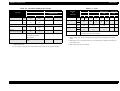
FEEDING METHOD
PAPER SPECIFICATIONS
Friction feed
: Front, Rear
Push tractor feed
: Front, Rear
Push & Pull tractor feed
: Front, Rear
Pull tractor feed
: Front, Rear, Bottom
Table 1-3. Cut Sheet (Single sheet, Not multi part) FX-890
Front Entry
FX-890
FEED SPEED
Normal mode
Copy mode
4.23 mm (1/6 inch feed)
Continuous feed
4.23 mm (1/6 inch feed)
Continuous feed
FEEDER
Front push tractor
Rear push tractor
CSF Bin 1 / Bin 2 (Option)
62 msec
0.127 MPS (m/sec)
[5.0 IPS (inches/sec)]
83 msec
0.078 MPS (m/sec)
[3.1 IPS (inches/sec)]
Manual
Manual
Rear Entry
High-Capacity
CSF
Min.
Max.
Single-Bin CSF
Min.
Max.
Min.
Max.
Min.
Max.
Width
(inch)
(mm)
(3.9)
100
(10.1)
257
(3.9)
100
(10.1)
257
(3.9)
100
(8.5)
216
(7.2)
182
(8.5)
216
Length
(inch)
(mm)
(3.9)
100
(14.3)
364
(3.9)
100
(14.3)
364
(3.9)
100
(14.3)
364
(8.3)
210
(14.3)
364
Thickness
(inch)
(mm)
(0.0025)
0.065
(0.0055)
0.14
(0.0025)
0.065
(0.0055)
0.14
(0.0028)
0.07
(0.0055)
0.14
(0.0028)
0.07
(0.0055)
0.14
Weight
(g/m2)
(lb)
52
(14)
90
(24)
52
(14)
90
(24)
64
(18)
90
(24)
64
(18)
90
(24)
CSF Capacity
---
---
185 sheets with the
60 sheets with the form
form 64 g/m2 (17lb) *1
64 g/m2 (17lb) *2
150 sheets with the
50 sheets with the form
form 82 g/m2 (22lb) *1
82 g/m2 (22lb) *2
Quality
Plain paper, Reclaimed paper
Not curled, not folded, not crumpled
Note : Printing on reclaimed paper is available only under normal temperature and humidity
conditions.
Note “*1”: When using High-Capacity CSF, paper total thickness is below 15 mm.
“*2” : When using Single-Bin CSF, paper total thickness is below 5 mm.
Pull tractor ( Option )
Roll paper holder (Option)
PRODUCT DESCRIPTIONS
Features
10
EPSON FX-890/2190
Revision B
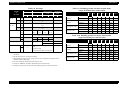
Table 1-4. Cut Sheet (Single sheet, Not multi part) FX-2190
Front Entry
FX-2190
Manual
Manual
Rear Entry
High-Capacity
CSF
Min.
Max.
Table 1-5. Cut Sheet (Multi part) FX-890
Front Entry
Single-Bin CSF
FX-890
Manual
Rear Entry
Manual / High-Capacity
CSF / Single-Bin CSF
Minimum
Maximum
Min.
Max.
Min.
Max.
Min.
Max.
Minimum
Maximum
Width
(inch)
(mm)
(3.9)
100
(16.5)
420
(3.9)
100
(16.5)
420
(3.9)
100
(16.5)
420
(7.2)
182
(16.5)
420
Width
(inch)
(mm)
(3.9)
100
(10.1)
257
-----
-----
Length
(inch)
(mm)
(3.9)
100
(16.5)
420
(3.9)
100
(16.5)
420
(3.9)
100
(16.5)
420
(8.3)
210
(14.3)
364
Length
(inch)
(mm)
(3.9)
100
(14.3)
364
-----
-----
Thickness
(inch)
(mm)
(0.0025)
0.065
(0.0055)
0.14
(0.0025)
0.065
(0.0055)
0.14
(0.0028)
0.07
(0.0055)
0.14
(0.0028)
0.07
(0.0055)
0.14
Copies
Weight
(g/m2)
(lb)
52
(14)
90
(24)
52
(14)
90
(24)
64
(18)
90
(24)
64
(18)
90
(24)
CSF Capacity
---
---
185 sheets with the
60 sheets with the form
form 64 g/m2 (17lb) *1
64 g/m2 (17lb) *2
150 sheets with the
50 sheets with the form
form 82 g/m2 (22lb) *1
82 g/m2 (22lb) *2
Quality
Plain paper, Reclaimed paper
Not curled, not folded, not crumpled
Note : Printing on reclaimed paper is available only under normal temperature and humidity
conditions
Note “*1”: When using High-Capacity CSF, paper total thickness is below 15 mm.
-----
Total thickness
(inch)
(mm)
(0.0047)
0.12
(0.018)
0.46
-----
-----
Weight
(g/m2)
(lb)
40
(12)
58
(15)
-----
-----
(one sheet of multi part)
Quality
Plain paper, Reclaimed paper
Not curled, not folded,
not crumpled
Jointing
Line glue at the top side of form
-----
-----
-----
Note1: Type of paper of multi-part forms should be Carbonless. Don’t use Carbon-backed and
Carbon-interleaved.
2: Type of paper of line glue at the top should be set jointing side of paper horizontally.
“*2” : When using Single-Bin CSF, paper total thickness is below 5 mm.
PRODUCT DESCRIPTIONS
1 original + 5 copies
Features
11
EPSON FX-890/2190
Revision B
Table 1-6. Cut Sheet (Multi part) FX-2190
Front Entry
FX-2190
Manual
Table 1-7. Card
Rear Entry
Manual / High-Capacity CSF
/ Single-Bin CSF
Minimum
Maximum
Front Entry
FX-890
&
FX-2190
Manual
Min. Max.
Minimum
Maximum
Width
(inch)
(mm)
(3.9)
100
(16.5)
420
-----
-----
Width
(inch) (3.9)
(mm) 100
Length
(inch)
(mm)
(3.9)
100
(16.5)
420
-----
-----
Length
(inch)
Copies
1 original + 5 copies
-----
Total thickness
(inch)
(mm)
(0.0047)
0.12
(0.018)
0.46
-----
Weight
(g/m2)
(lb)
40
(12)
58
(15)
-----
(one sheet of multi part)
Quality
Jointing
Line glue at the top side of
form
Single-Bin
CSF
Min. Max.
Min.
Max.
(3.9)
100
(5.8)
148
(3.9)
100
(5.8)
148
---
---
(3.9)
100
(5.8)
148
(3.9)
100
(5.8)
148
---
---
(mm)
(5.8)
148
Thickness
(inch)
(mm)
(0.0087)
0.22
(0.0087)
0.22
(0.0087)
0.22
---
---
Weight
(g/m2)
192
(51)
192
(51)
192
(51)
---
---
-----
(lb)
-----
Quality
Plain paper, Reclaimed paper
Not curled, not folded,
not crumpled
(5.8)
148
Manual
Rear Entry
High-Capacity
CSF
Min.
Max.
-----
Plain paper, Reclaimed paper
Not curled, not folded, not crumpled
Note1: Printing on card is available only under normal temperature and humidity conditions
-----
2: When setting cards, be sure to align their left edge with the matchmark of the sheet
guide.
-----
3: When Paper size is A6 and the sheet is to be set horizontal, it should be inserted from
rear entrance only.
Note1: Type of paper of multi-part forms should be Crbonless. Don’t use Carbon-backed and
Carbon-interleaved.
4: When using card, set up card mode.
2: Type of paper of line glue at the top should be set jointing side of paper horizontally.
PRODUCT DESCRIPTIONS
Features
12
EPSON FX-890/2190
Revision B
Table 1-8. Envelope
Front Entry
FX-890
&
FX-2190
Manual
Min. Max.
Envelope Width (inch)
(mm)
(No.6)
Length (inch)
Manual
Min.
Max.
(6.5)
165
-----
-----
(3.6)
92
-----
-----
(9.5)
241
-----
(4.1)
105
-----
-----
(mm)
Total Thickness
Weight
(inch)
(mm)
(g/m2)
-----
(0.0063)
0.16
(0.0205)
0.52
-----
-----
The difference of thickness at the printable
area is within 0.25 mm (0.0098 inch)
-----
-----
(lb)
CSF capacity
Single-Bin
CSF
Min. Max.
-----
(mm)
Envelope Width (inch)
(mm)
(No.10)
Length (inch)
Rear Entry
High-Capacity
CSF
Min.
Max.
-----
Quality
-----
(0.0205)
0.52
(0.0063)
0.16
45
90
45
90
(12)
(24)
(12)
(24)
Table 1-9. Handling possible cut sheets of fixed forms
(single sheet/multi-part) with FX-890
Size
Direction
A5
A6
Envelope
{/---
Horizontal
---/---
---/---
---/---
Front Entry
(manual)
Vertical
---/---
{/{
Horizontal
---/---
---/---
---/---
{ /{ { /{ { /{
---
Vertical
---/---
---/---
{/--- {/--- {/--- {/---
---
Horizontal
---/---
---/---
---/---
Vertical
---/---
---/---
{/--- {/---
---
---
---
Horizontal
---/---
---/---
---/---
---
---
---
High-Capacity CSF
Single-Bin CSF
{/--- {/--- {/--- {/---
---
{/--- {/--- {/---
{
{ /{ { /{ { /{ { /{
---
{/--- {/--- {/-----/---
{
Table 1-10. Handling possible cut sheets of fixed forms
(single sheet/multi-part) with FX-2190
----
Direction
30 sheets (12lb)
----
BOND paper, PLAIN paper or AIR
MAIL
No glue at a flap
Not curled, not folded, not crumpled
-----
Rear Entry
(manual)
Front Entry
(manual)
2: Set the longer side of envelope horizontally.
B5
---/---
Size
3: When setting envelopes of No. 6 paper size, be sure to align their left edge with the
matchmark of the sheet guide.
A4
Vertical
-----
Note1: Printing on envelope is available only under normal temperature and humidity
conditions
B4
Rear Entry
(manual)
25 sheets (24lb)
-----
A3
High-Capacity CSF
Single-Bin CSF
A3
B4
A4
B5
A5
A6
Vertical
{/---
{/---
{/--- {/--- {/--- {/---
---
Horizontal
{/---
{/---
{/--- {/--- {/--- {/---
{
Vertical
{/{
{/{
{ /{ { /{ { /{ { /{
---
Horizontal
{/{
{/{
{ /{ { /{ { /{ { /{
---
Vertical
TBD
TBD
TBD
TBD
TBD
TBD
TBD
Horizontal
TBD
TBD
TBD
TBD
TBD
TBD
TBD
Vertical
TBD
TBD
TBD
TBD
TBD
TBD
TBD
Horizontal
TBD
TBD
TBD
TBD
TBD
TBD
TBD
Envelope
4: Envelope should be inserted from rear entrance only.
5: Except for AIRMAIL, the sheets stacked must not exceed 4 sheets.
6: Printing is allowed only on the front side; printing on the back side is impossible.
PRODUCT DESCRIPTIONS
Features
13
EPSON FX-890/2190
Revision B
Table 1-11. Continuous paper (Single sheet and Multi Part) FX-890
Table 1-12. Continuous paper (Single sheet and Multi Part) FX-1190
Bottom/Front/Rear Entry
Minimum
Maximum
FX-890
Bottom/Front/Rear Entry
Minimum
Maximum
FX-2190
Width
(inch)
(mm)
(4)
101.6
(10)
254
Width
(inch)
(mm)
(4)
101.6
(16)
406.4
Length (one page)
(inch)
(mm)
(4)
101.6
(22)
558.8
Length (one page)
(inch)
(mm)
(4)
101.6
(22)
558.8
1 original + 5 copies *
Copies
1 original + 5 copies *
Copies
Total thickness
(inch)
(mm)
(0.0025)
0.065
(0.018)
0.46
Total thickness
(inch)
(mm)
(0.0025)
0.065
(0.018)
0.46
Weight
(not multi part)
(g/m2)
(lb)
52
(14)
82
(22)
Weight
(not multi part)
(g/m2)
(lb)
52
(14)
82
(22)
Weight
(one sheet of multi part)
(g/m2)
(lb)
40
(12)
58
(15)
Weight
(one sheet of multi part)
(g/m2)
(lb)
40
(12)
58
(15)
Quality
Plain paper, Reclaimed paper
Carbonless multi part paper
Not break, without wrinkle, without tear,
without turn over
Quality
Plain paper, Reclaimed paper
Carbonless multi part paper
Not break, without wrinkle, without tear,
without turn over
Jointing
Point glue or paper staple(both side)
Jointing
Point glue or paper staple(both side)
Note “*” : When pull tractor is used, 1 original + 6 copies are available only under normal
temperature and humidity conditions.
PRODUCT DESCRIPTIONS
Note “*” : When pull tractor is used, 1 original + 6 copies are available only under normal
temperature and humidity conditions.
Features
14
EPSON FX-890/2190
Revision B
Table 1-14. Labels (FX-2190)
Table 1-13. Labels (FX-890)
Bottom/Front Entry
Minimum
Maximum
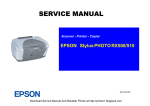
See Figure 1-1 below.
FX-890
Label size
Rear Entry
Minimum Maximum
Label size
-----
Base sheet width
(inch)
(mm)
(4)
101.6
(10)
254
-----
-----
Base sheet length
(one page)
(inch)
(mm)
(4)
101.6
(22)
558.8
-----
Base sheet
Thickness
(inch)
(mm)
(0.0028)
0.07
(0.0035)
0.09
Total thickness
(inch)
(mm)
(0.0063)
0.16
(0.0075)
0.19
Label weight
(g/m2)
(lb)
Quality
Bottom/Front Entry
Minimum
Maximum
See Figure 1-1 below.
FX-2190
Rear Entry
Minimum Maximum
-----
Base sheet width
(inch)
(mm)
(4)
101.6
(16)
406.4
-----
-----
-----
Base sheet length
(one page)
(inch)
(mm)
(4)
101.6
(22)
558.8
-----
-----
-----
-----
Base sheet
Thickness
(inch)
(mm)
(0.0028)
0.07
(0.0035)
0.09
-----
-----
-----
-----
Total thickness
(inch)
(mm)
(0.0063)
0.16
(0.0075)
0.19
-----
-----
-----
Label weight
(g/m2)
(lb)
-----
Quality
64
(17)
Plain paper or the same quality
labels
Note1: Printing on labels is available only under normal temperature and humidity conditions.
64
(17)
Plain paper or the same quality
labels
---------
Note1: Printing on labels is available only under normal temperature and humidity conditions.
2: The base sheet of labels must be continuous paper.
2: The base sheet of labels must be continuous paper.
3: Labels should be inserted from bottom or front entrance.
3: Labels should be inserted from bottom or front entrance.
4: Do not pull out paper from backward.
4: Don’t pull out paper from backward.
5: No label paper should be left on the printer when the printer is not used.
5: No label paper should be left on the printer when the printer is not used.
6: Do not print on the base sheet of labels.
6: Don’t print on the base sheet of labels.
7: Do not use cut sheet labels.
7: Don't use cut sheet labels.
Figure 1-1. Label Size
PRODUCT DESCRIPTIONS
Features
15
EPSON FX-890/2190
Revision B
CHARACTER TABLES
Table 1-15. Roll Paper
FX-890&
FX-2190
Bottom/Front Entry
Minimum
Maximum
Rear Entry
Minimum
Maximum
Standard version
: 13 tables
Width
(inch)
(mm)
-----
(8.5)
216
NLSP version
: 42 tables
Length
(inch)
(mm)
-----
-----
International character sets
: 13 countries
Diameter
(inch)
(mm)
-----
Thickness
(inch)
(mm)
-----
(0.0028)
0.07
(0.0035)
0.09
Weight
(g/m2)
(lb)
-----
52
(14)
82
(22)
Quality
-----
(5)
INPUT BUFFER
φ127 mm
128 Kbyte
Plain paper, not curled, not
folded, not crumpled
Note1: Roll paper must be set on the roll paper holder (option).
2: Roll paper should be inserted from rear entrance only.
3: Release lever position should be friction.
TYPEFACE
Bit map font
EPSON Draft
: 10 cpi, 12 cpi, 15 cpi
EPSON Roman
: 10 cpi, 12 cpi, 15 cpi, Proportional
EPSON Sans Serif
: 10 cpi, 12 cpi, 15 cpi, Proportional
EPSON OCR-B
: 10 cpi *
Bar code fonts:
EAN-13, EAN-8, Interleaved 2 of 5, UPC-A, UPC-E, Code 39, Code 128,
POSTNET, Coda bar (NW-7)*, Industrial 2 of 5*, Matrix 2 of 5*
NOTE: “*”: These fonts are not described in user’s manual.
PRODUCT DESCRIPTIONS
Features
16
EPSON FX-890/2190
Revision B
ELECTRICAL SPECIFICATION
Table 1-18. UPS Version
Table 1-16. 120V Version
Rated voltage
AC 120 V
Input voltage range
AC 103.5 to 132 V
Rated frequency range
50 to 60 Hz
Input frequency range
49.5 to 60.5 Hz
Rated current
1.1 A (Max. 2.5 A)
Power consumption
Approx.53 W (ISO/IEC 10561 Letter pattern)
Approx. 3.5 W in sleep mode *
0 W in power off mode
Energy Star compliant
Insulation resistance
10 MΩ min. (between AC line and chassis, DC 500 V)
Dielectric strength
AC 1000 V rms. 1 min. or AC 1200 V rms. 1 sec.
(between AC line and chassis)
Table 1-17. 230V Version
Rated voltage range
AC 220 to 240 V
Input voltage range
AC 198 to 264 V
Rated frequency range
50 to 60 Hz
Input frequency range
49.5 to 60.5 Hz
Rated current
0.6 A (Max. 1.3A)
Power consumption
Approx. 53 W (ISO/IEC 10561 Letter pattern)
Approx. 3.5 W in sleep mode *
0 W in power off mode
Energy Star compliant
Insulation resistance
10 MΩ min. (between AC line and chassis, DC 500 V)
Dielectric strength
AC 1500 V rms. 1 min. (between AC line and chassis)
PRODUCT DESCRIPTIONS
Rated voltage range
AC 100 to AC240V
Input voltage range
AC 90 to 264V
Rated frequency range
50 to 60 Hz
Input frequency range
49.5 to 60.5 Hz
Rated current
1.1 A (Max. 3.0 A)
Power consumption
Approx.56 W (ISO/IEC 10561 Letter pattern)
Approx. 4.0 W in sleep mode *
0 W in power off mode
Energy Star compliant
Insulation resistance
10 MΩ min. (between AC line and chassis, DC 500 V)
Dielectric strength
AC 1500 V rms. 1 min. ( between AC line and chassis)
Note “*” : Upon a lapse of 5 minutes under the following conditions, the printer enters sleep
mode:
• Not in Pause, not in error status
• There is no data in input buffer.
Features
17
EPSON FX-890/2190
Revision B
ACOUSTIC NOISE
Level:
55 dB(A) (ISO 7779 pattern)
Color
Black
Ribbon dimensions
13 mm (W) x 17 M (L) Endless
Ribbon life
Approximately 7.5 million characters
(Draft 10 cpi, 14 dots / character)
Cartridge dimensions
287 mm (W) x 30 mm (H) x 77 mm (D)
ENVIRONMENTAL CONDITIONS
Temperature :
Humidity :
Resistance to shock :
5 to 35°C (operating, *1)
15 to 25°C (operating, *1,*2)
<FX-2190>
-30 to 60°C (non-operating)
Type
Fabric
10 to 80 % RH (operating, *1)
Color
Black
30 to 60 % RH (operating, *1,*2)
Ribbon dimensions
13 mm (W) x 19 M (L) Endless
0 to 85 % RH (non-operating)
Ribbon life
Approximately 12 million characters
(Draft 10 cpi, 14 dots / character)
Cartridge dimensions
468.5 mm (W) x 34 mm (H) x 78 mm (D)
1 G, within 1ms (operating)
2 G, within 2ms (non-operating)
Resistance to vibration :
0.25 G, 10 to 55 Hz (operating)
SAFETY APPROVALS
0.50 G, 10 to 55 Hz (non-operating)
120 V version
*1: without condensation
*2: during printing on reclaimed paper, multi part paper, envelope, label or roll paper
RELIABILITY
Safety standards
UL 1950, CSA C22.2 No. 950
EMI
FCC part 15 subpart B class B, CSA C108.8 class B
230 V version
Total print volume (MVBF)
52 million lines (except print head)
Safety standards
EN60950
MTBF
20000 POH (25% Duty)
EMI
Print head life
400 million strokes/wire
(Approx. 400 million characters (Draft 10 cpi, 14 dots/
character))
EN55022 ( CISRP pub.22 ) class B
AS/NZS.3548 class B
UPS Version
RIBBON CARTRIDGE
<FX-890>
Type
Safety standards
UL 1950, CSA C22.2 No. 950
EN60950
EMI
FCC part 15 subpart B class B, CSA C108.8 class B
EN55022 (CISPR pub. 22) class B
AS/NZS 3548 class B
Fabric
PRODUCT DESCRIPTIONS
Features
18
EPSON FX-890/2190
Revision B
CE MARKING
EXPENDABLES & OPTIONS
Table 1-19. Expendables & Option
230 V version & UPS version
Expendables
Low Voltage Directive 73/23/EEC: EN60950
EMC Directive 89/336/EEC:
EN55022 class B
EN61000-3-2
EN61000-3-3
EN55024
INTERFACE
Bi-directional parallel interface (IEEE-1284 nibble mode supported)
USB (ver1.1) I/F
Type-B I/F level 2 (Option)
CONTROL CODE
ESC/P
IBM PPDS emulation
Ribbon cartridge (Black)
Code No.
FX-890
FX-2190
S015329
S015327
Options
High capacity cut sheet feeder (Bin 1)
C80638*
C80640*
Single bin cut sheet feeder (Bin 2)
C80637*
C80639*
Pull tractor unit
C80020*
C80021*
#8310
#8310
Roll paper holder
Front sheet guide
C81400*
C81401*
Front paper guide
C81402*
C81403*
Serial Interface card
C82305* / C82306*
C82305* / C82306*
32KB intelligent serial Interface card
C82307* / C82308*
C82307* / C82308*
Local Talk I/F card
C82312*
C82312*
32KB IEEE-488 I/F card
C82313*
C82313*
Coax I/F card
C82314*
C82314*
Twinax I/F card
C82315*
C82315*
IEEE-1284 parallel I/F card
C82345*
C82345*
EpsonNet 10 Base 2/T Int. Print Server
C82362*
C82362*
EpsonNet 10/100 Base Tx Int. Print Server
C82363* *1/C82364*
C82363* *1/C82364*
EpsonNet 10/100 Base Tx Int. Print Server
C82384*
C82384*
EpsonNet 10/100 Base Tx Int. Print Server 2
C82391*
C82391*
EpsonNet 802.11b Wireless Ext. Print Server
C12C82396*
C12C82396*
Note “*1”: When you use Ethernet interface card C82363*, you need to attach the optional
interface adapter (C82525*) to the interface card.
PRODUCT DESCRIPTIONS
Features
19
EPSON FX-890/2190
Revision B
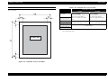
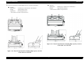
PRINTABLE AREA
Table 1-20. Printable Area for Cut Sheet
Single Sheet / Multi Part
Cut sheets
PW (Width)
PL (Length)
LM (Left Margin)
RM (Right Margin)
TM (Top Margin)
BM (Bottom Margin)
FX-890
FX-2190
Refer to “PAPER
SPECIFICATIONS” Table 1-3 on
page 10 for single sheet or
Table 1-5 on page 11 for multi
part
Refer to “PAPER
SPECIFICATIONS” Table 1-4 on
page 11 for single sheet or
Table 1-6 on page 12 for multi
part
3 mm or more (PW<=209.2 mm)
26.9 mm or more (PW=257 mm)
3 mm or more (PW<=351.4 mm)
37.3 mm or more (PW=420 mm)
4.2 mm or more
Note : The maximum horizontal printable area is 203.2 mm (8 inch) for FX-890 or 345.4 mm
(13.6 inch) for FX-2190.
Printable Area
Figure 1-2. Printable Area for Cut Sheet
PRODUCT DESCRIPTIONS
Features
20
EPSON FX-890/2190
Revision B
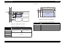
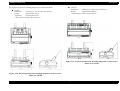
Continuous paper
Envelope
PW
LM
RM
TM
Printable Area
PL
Printable Area
Figure 1-3. Printable Area for Envelope
BM
Table 1-21. Printable Area for Envelope
Envelope Printable Area
PW (Width)
PL (Length)
Figure 1-4. Printable Area for Continuous Paper
Refer to “PAPER SPECIFICATIONS” Table 1-8 on page 13
LM (Left Margin)
RM (Right Margin)
TM (Top Margin)
BM (Bottom Margin)
Table 1-22. Printable Area for Continuous Paper
3 mm or more
Continuous Paper
4.2 mm or more
FX-890
PW (Width)
PL (Length)
LM (Left Margin)
RM (Right Margin)
TM (Top Margin)
BM (Bottom Margin)
PRODUCT DESCRIPTIONS
Features
FX-2190
Refer to “PAPER
SPECIFICATIONS” Table 1-11
on page 14
Refer to “PAPER
SPECIFICATIONS” Table 1-12
on page 14
13 mm or more (PW<=241.3mm,
9.5 inches)
26 mm or more (PW=254 mm,
10 inches)
13 mm or more (PW<=377.8mm,
14.875 inches)
26 mm or more (PW=406.4 mm,
16 inches)
4.2 mm or more
21
EPSON FX-890/2190
Revision B
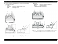
Label
Roll paper
PW
LM
RM
TM
1.2mm
or more
PW
TM LM
RM
Printable area
PL
Printable area
BM
6.35mm
or more
Figure 1-6. Printable Area for Roll Paper
Table 1-24. Printable Area for Roll Paper
Roll Paper
Figure 1-5. Printable Area for Label
PW (Width)
PL (Length)
LM (Left Margin)
Table 1-23. Printable Area for Label
RM (Right Margin)
Continuous Paper
FX-890
PW (Width)
PL (Length)
FX-2190
Refer to “PAPER
SPECIFICATIONS” Table 1-13
on page 15
Refer to “PAPER
SPECIFICATIONS” Table 1-14
on page 15
TM (Top Margin)
BM (Bottom Margin)
Refer to “PAPER SPECIFICATIONS” Table 1-15 on page 16
----3 mm or more
3 mm or more
4.2 mm or more
-----
LM (Left Margin)
RM (Right Margin)
TM (Top Margin)
3 mm or more
BM (Bottom Margin)
PRODUCT DESCRIPTIONS
Features
22
EPSON FX-890/2190
Revision B
1.2 Interface
Table 1-25. Connector pin assignment (Forward channel) (continued)
This printer provides bi-directional 8-bit parallel interface, USB interface and Type-B
optional interface slot as standard.
1.2.1 Parallel interface (Forward channel)
Specifications
Pin
No.
Signal
Name
Return
GND
Pin
IN/
Out*
Function description
12
PE
28
Out
This signal’s high level means that the printer is in
a state of paper-out error.
13
SLCT
28
Out
Always at high level when the power to the printer
is on.
14
-AFXT
30
In
Not used.
31
-INIT
30
In
This signal’s negative pulse initializes printer.
32
-ERROR
29
Out
This signal’s low level means the printer is in a
state of error.
Transmission mode:
8 bit parallel, IEEE-1284 compatibility mode
Adaptable connector:
57-30360 (Amphenol) or equivalent
Synchronization:
-STROBE pulse
Handshaking :
BUSY and -ACKNLG signals
36
-SLIN
30
In
Signal level:
TTL compatible (IEEE-1284 level 1 device)
18
Logic H
-
Out
This line is pulled up to +5 V through 3.9 kΩ
resistor.
35
+5 V
-
Out
This line is pulled up to +5 V through 1.0 kΩ
resistor.
17
Chassis
-
-
Chassis GND.
Table 1-25. Connector pin assignment (Forward channel)
Not used.
Pin
No.
Signal
Name
Return
GND
Pin
IN/
Out*
Function description
16, 33
19-30
GND
-
-
Signal GND.
1
-STROBE
19
In
Strobe pulse. Input data is latched at falling edge of
the signal.
15, 34
NC
-
-
Not connected.
2
DATA1
20
In
Parallel input data to the printer.
3
DATA2
21
In
bit 1
4
DATA3
22
In
bit 2
5
DATA4
23
In
bit 3
6
DATA5
24
In
bit 4
7
DATA6
25
In
bit 5
8
DATA7
26
In
bit 6
9
DATA8
27
In
bit 7: MSB
10
-ACKNLG
28
Out
This signal (negative pulse) indicates that the
printer has received data and is ready to accept next
one.
11
BUSY
29
Out
This signal’s high level means that the printer is not
ready to accept data.
PRODUCT DESCRIPTIONS
bit 0: LSB
Note : In/Out shows the direction of signal flow from the printer’s point of view.
Interface
23
EPSON FX-890/2190
Revision B
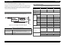
Data transmission timing
BUSY signal is active (high level) under any of the following conditions:
In the process of receiving data
DATA
Input buffer full
data byte n+1
data byte n
t hold
-INT signal active (low level)
-STROBE
t setup
During hardware initialization
t next
t stb
-ERROR or PE signal active (low level or high level, respectively)
BUSY
In the self test mode
t ready
t busy
In the adjustment mode
-ACKNLG
t reply
In the default-setting mode
t ack
t nbusy
Figure 1-7. Data transmission timing
-ERROR signal is active (low level) under any of the following conditions:
In the condition of the printer hardware error (fatal error)
In the condition of the paper-out error
Table 1-26. Parameters
Parameter
Minimum
Maximum
t setup
500 nsec
_
t hold
500 nsec
_
t stb
500 nsec
_
t ready
0
_
t busy
_
500 nsec
t reply
_
_
t ack
500 nsec
10 us
t nbusy
0
_
t next
0
_
t tout*1
_
120 nsec
t tin*2
_
200 nsec
In the condition of the release lever error
In the condition of the cover open error
In the condition of the paper eject error
PE signal is active (high level) under the following condition:
In the condition of paper-out error
Note “*1”: Rise and fall time of output signals
“*2” : Rise and fall time of input signals
PRODUCT DESCRIPTIONS
Interface
24
EPSON FX-890/2190
Revision B
FX-2190
1.2.2 Parallel interface (Reverse channel)
When IEEE1284.4 is enabled,
Specifications
Transmission mode :
IEEE-1284 nibble mode
[00H][4EH]
Adaptable connector:
57-30360 (Amphenol) or equivalent
MFG:EPSON;
Synchronization :
Refer to the IEEE-1284 specification
Handshaking :
Refer to the IEEE-1284 specification
Signal level:
TTL compatible (IEEE-1284 level 1 device)
CMD:ESCP9,PRPII9,BDC,D4;
MDL:FX-2190;
CLS:PRINTER;
DES:EPSON[SP]FX-2190;
Data transmission timing : Refer to the IEEE-1284 specification
Extensibility request :
The printer responds to the extensibility request in
the affirmative, when the request is 00H or 04H,
which mean;
00H : Request nibble mode of reverse channel transfer
04H : Request device ID in nibble mode of reverse channel transfer
Device ID: The printer sends the following device ID string when it is requested
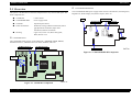
When IEEE1284.4 is disabled,
[00H][4BH]
MFG:EPSON;
CMD:ESCP9,PRPII9,BDC;
MDL:FX-2190;
CLS:PRINTER;
FX-890
DES:EPSON[SP]FX-2190;
When IEEE1284.4 is enabled,
[00H][4CH]
MFG:EPSON;
CMD:ESCP9,PRPII9,BDC,D4;
MDL:FX-890;
CLS:PRINTER;
DES:EPSON[SP]FX-890;
When IEEE1284.4 is disabled,
[00H][49H]
MFG:EPSON;
CMD:ESCP9,PRPII9,BDC;
MDL:FX-890;
CLS:PRINTER;
DES:EPSON[SP]FX-890;
PRODUCT DESCRIPTIONS
Interface
25
EPSON FX-890/2190
Revision B
1.2.3 USB Interface
Table 1-27. Connector pin assignment (Reverse channel)
1
HostClk
Return
GND
Pin
19
2
DATA1
3
Pin No. Signal Name
IN/
Out*
Specifications
Function description
Standard:
Based on
“Universal Serial Bus Specifications
Revision 1.1”
“Universal Serial Bus Device Class
Definition for Printing Devices Version 1.1”
Bit rate :
12 Mbps (Full Speed Device)
Data encording :
NRZI
bit 5
Adaptable connector :
USB Series B
In
bit 6
Recommended cable length : 2 meters
In
bit 7: MSB
In
Host clock signal.
20
In
Parallel input data to the printer.
DATA2
21
In
bit 1
4
DATA3
22
In
bit 2
5
DATA4
23
In
bit 3
6
DATA5
24
In
bit 4
7
DATA6
25
In
8
DATA7
26
9
DATA8
27
10
PtrClk
28
Out
Printer clock signal.
11
PtrBusy /
DataBit-3,7
29
Out
Printer busy signal and reverse channel transfer
data bit 3 or 7.
12
AckDataReq /
DataBit-2,6
28
Out
Acknowledge data request signal and reverse
channel transfer data bit 2 or 6.
13
Xflag /
DataBit-1,5
28
Out
X-flag signal and reverse channel
transfer data bit 1 or 5.
14
HostBusy
30
In
Host Busy signal.
31
-INIT
30
In
Not used.
32
-DataAvail /
DataBit-0,4
29
Out
36
1284-Active
30
In
18
Logic-H
-
Out
This line is pulled up to +5 V through 3.9 kΩ
resistor.
35
+5 V
-
Out
This line is pulled up to +5 V through 1.0 kΩ
resistor.
17
Chassis
-
-
Chassis GND.
16, 33
19-30
GND
-
-
Signal GND.
15, 34
NC
-
-
Not connected.
bit 0: LSB
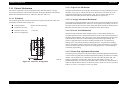
Connector pin assignment and signals :
Table 1-28. Connector pin assignment
Pin No. Signal name
Data Available signal and reverse channel transfer
data bit 0 or 4.
In/Out
-
Function description
Cable power. Maximum power consumption is
100mA
1
VCC
2
-Data
Bi-directional Data
3
+Data
Bi-directional Data, pull up to +3.3V via 1.5K Ω resistor
4
Ground
-
Pin #2
Cable ground
Pin #1
1284 active signal.
Pin #3
Pin #4
Figure 1-8. USB Interface connector pin assignment
Note : In/Out refers to the direction of signal flow from the printer’s point of view.
PRODUCT DESCRIPTIONS
Interface
26
EPSON FX-890/2190
Revision B
1.2.4 Optional Interface
1.2.5 Type-B Interface communication specification
Type-B optional interface cards are available.
Reply for Optional command
(*: Reply for Type-B I/F Level 2 device: not described in user's manual)
Table 1-29. FX-890
Reply message
Main-Type
Product-Name
ESC/P
MT9p, PW80c110cpi,
PRG(Wxxxxx)rev, AP500ma
IBM PPDS
MT9p, PW80c110cpi,
PRG(Wxxxxx)rev, AP500ma
FX-890
FX-890
Table 1-31. Reply for Optional command
Option command
Command name
number
00h
No-operation
Reply-A
Reply-B
-----
-----
Emulation-Type ESCP9, PRPII9, BDC
ESCP9, PRPII9, BDC
01h
Start Hardware Reset
Accept*
Execute OK*
Entity-Type
EPSONPRPII9
02h
Start Software Reset
Reject
-----
03h
Send Main System Type
Accept
Execute OK
04h
Send Name Data
Reject
-----
05h
Inquire Name Data
Accept
Execute OK
06h
Send Product Name
Accept
Execute OK
07h
Send Software Emulation Type
Accept
Execute OK
08h
Complete Buffered Data
Accept
Execute OK
09h
Stop Procedure
Reject
-----
0Ah
Return Buffered Data
Reject
-----
0Bh
Send Entity Type
Accept
Execute OK
0Ch
Send Status
Accept
Execute OK
0Dh
Quit Procedure
Reject
-----
0Eh
Inquire ASCII Message
Reject
-----
0Fh
Send ASCII Message
10h
(Reserved)
11h
EPSONFX
Table 1-30. FX-2190
Reply message
Main-Type
Product-Name
ESC/P
MT9p, PW136c110cpi,
PRG(Wxxxxx)rev, AP500ma
IBM PPDS
MT9p, PW136c110cpi,
PRG(Wxxxxx)rev, AP500ma
FX-2190
FX-2190
Emulation-Type ESCP9, PRPII9, BDC
ESCP9, PRPII9, BDC
Entity-Type
EPSONPRPII9
EPSONFX
Accept
Execute OK
Unknown
-----
Send All Entity Type
Reject
-----
12h
Inquire Protocol
Reject
-----
13h
(Reserved)
Unknown
-----
14h
Inquire Emergency Message
Accept
Execute OK
15h
Send Emergency Reply
Accept
Execute OK
Unknown
-----
16h-17h
PRODUCT DESCRIPTIONS
Interface
(Reserved)
27
EPSON FX-890/2190
Revision B
Main command
1.2.6 Interface selection
Table 1-32. Main command
Option command
number
01h
Command name
Sending Timing
•
•
•
•
•
Init signal on the std. parallel
Type-B I/F Option command : 01h
Panel Reset
Cold start
Deciding the level of Type-B I/F
after power on
• Type-B I/F Option command: 05h
Start Software Reset
02h
Send Option Type
04h
Send Name Data
07h
0Eh
Inquire Software Emulation Type • Changing control language
• Writing to DBIN-register
Inquire ASCII Message
14h
Inquire Emergency Reply
15h
Send Emergency Message
Back Ground Job command:
“0x00”: get device
“0x01”: get all status
“0x02”~“0x3F”
• Reply for Back Ground Job
command response
• Receive back Ground Job
command
The printer has 3 interfaces; the parallel interface, USB interface and Type-B optional
interface. These interfaces are selected manually by Default Setting or selected
automatically.
Manual selection
One of the three interfaces can be selected by Default Setting.
Automatic selection
The automatic interface selection is enabled by Default Setting. In this automatic
interface selection mode, the printer is initialized to the idle state scanning which
interface receives data at power-on. Then the interface that receives data first is
selected. When the host stops data transfer and the printer is in the stand-by state
for the period of seconds specified by Default Setting, the printer is returned to the
idle state. As long as the host sends data or the printer interface is the busy state,
the selected interface is let as it is.
Interface state and interface selection
When the parallel interface is not selected, the interface gets info a busy state.
When the Type-B serial interface card is installed and it is not selected, the
interface sends XOFF and sets the DTR signal MARK. When the optional
interface is not selected, the printer sets “OFFLINE” bit of MNSTS register to the
optional interface. When the printer is initialized or returned to the idle state, the
parallel interface got into a ready state, the serial interface sends XON and sets the
DTR SPACE and the printer resets “OFFLINE” bit of MNSTS register to the
optional interface. Note that the interrupt signal such as a -INIT signal on the
parallel interface is not effective while that interface is not selected.
Response
ID Normal response
Normal response
Processing impossible response
A bit rate available by Serial I/F card :
19200bps, 9600bps, 4800bps, 2400bps, 1200bps, 600bps, 300bps
Preventing Hosts from Data Transfer Timeout
Generally, hosts abandons data transfer to peripherals when a peripheral is in the
busy state for dozens of seconds continuously. To prevent hosts from this kind of
timeout, the printer receives data very slowly, several bytes per minute, even if the
printer is in the busy state. This slowdown is started when the rest of the input
buffer becomes several thousands of bytes. At last, when the input buffer is full,
the printer is in the busy state continuously.
IEEE1284.4 on the parallel interface and on the USB interface do not require this
function.
PRODUCT DESCRIPTIONS
Interface
28
EPSON FX-890/2190
Revision B
1.2.7 IEEE1284.4 protocol
The packet protocol described by IEEE1284.4 is supported on the parallel I/F.
Two function modes of IEEE1284.4 protocol, “Off” and “Auto”, are available and
one of them is selected according to the value of Default setting. (See Section
1.3.5. Default Setting).
NOTE:Packet protocol option “Off” &“Auto” in Default setting mode are effective in
not only parallel I/F but also USB I/F.
Auto:
Communication is carried out in the convetional mode until a magic
string (1284.4 synchronous commands) is received. By receiving a
magic string, communication in IEEE1284.4 packet mode is started.
Off:
Communication is carried out in the convetional mode.
NOTE:The packet protocol of IEEE1284.4 allows a device to carry on multiple
exchanges or conversations which contain data and/or control information
with another device at the same time across a single point-to-point link. The
protocol is not, however, a device control language. It does provide basic
transport-level flow control and multiplexing services. The multiplexed
logical channels are independent of each other and blocking of one has no
effect on the others. The protocol operates over IEEE1284.
PRODUCT DESCRIPTIONS
Interface
29
EPSON FX-890/2190
Revision B
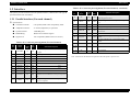
1.3 Operation
1.3.2 Switches
This section describes the operations on this printer.
1.3.2.1 Operation in Normal Mode
In the normal mode, pressing panel switches executes the following functions.
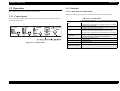
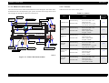
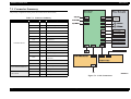
1.3.1 Control panel
Table 1-33. Normal Mode
The control panel of this printer is equipped with 6 switches and 10 LEDs, which are
located as shown below.
Switch
Font
Pitch
• Selects pitch.
Reset (Font & Pitch)
• Resets the printer.
Pause
Load/Eject
LF/FF
Tear Off/Bin
Figure 1-9. Control Panel
Function
Alternates printing and no-printing status.
Enables Micro Adjust function, holding it down for 3 seconds.
Loads or ejects the paper.
Executes micro feed forward, when this function is enabled.
Executes line feed, pressing it shortly.
Executes form feed, holding it down for a few seconds.
Executes micro feed backward, when this function is enabled.
Advances continuous paper to the Tear-Off position.
Selects CSF bin 1/2 or Card mode in friction mode.
Selects font and draft quality.
•
•
•
•
•
•
•
•
•
•
• Enter or exit the default setting mode.
Menu
(Pitch & Tear Off/Bin)
PRODUCT DESCRIPTIONS
Operation
30
EPSON FX-890/2190
Revision B
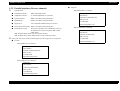
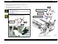
1.3.2.2 Operations at Power-on
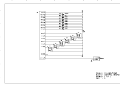
1.3.3 Indicators ( LEDs )
Holding down the specified switch (switches) while turning on the power to the printer
enables the special functions as listed below.
This printer has the following indicators to indicate its current condition, as shown in
the table below:
Table 1-34. At Power-On
Switches
1.3.3.1 Indications in Normal Mode
Function
Load/Eject
Table 1-36. Normal Mode
NLQ self test
LF/FF
Draft self test
Load/Eject & LF/FF
Data dump
LED
Printer status
Pause
Load/Eject & LF/FF & Pause
Clear EEPROM
Paper out error
On
On
_
_
_
Tear Off/Bin & Load/Eject
Clear EEPROM for Driving Line count for ribbon change
timing
Release lever error
On
_
_
_
_
Paper eject error
On
Blink
_
_
_
Pause
Bi-D adjustment
Head hot warning
Blink
_
_
_
_
Load/Eject & Pause
Panel lock out mode
Micro Adjust
Blink
_
_
_
_
LF/FF & Pause
Default setting for panel lock out
Tear off
_
_
*3
_
_
1.3.2.3 Operation in Default Setting Mode
Table 1-35. Default Setting Mode
Switch
Menu (Pitch & Tear Off/Bin)
Function
Enter or exit the default setting mode.
Item ↑ (Font), Item ↓ (Pitch)
Select the menu.
Set (Tear Off/Bin)
Changes the setting.
The others
Not available
Pause
*1
On
Paper Out
*2
_
Tear-Off /
Bin
_
Font
Pitch
_
_
Bin selection
_
_
*3
_
_
Font selection
_
_
_
*4
_
Pitch selection
_
_
_
_
*5
Locked switch pressed
*6
*6
_
_
_
Blink
Blink
Blink
Blink
Blink
Fatal error
*1. Pause ( Orange )
The “Pause” LED is on when the printer is in the pause status, and off when it
is not in the pause status.
The “Pause” LED blinks when the Micro Adjust function is enabled or when
the printer is in the head hot status.
See *6 for LED indication when a locked switch is pressed.
PRODUCT DESCRIPTIONS
Operation
31
EPSON FX-890/2190
Revision B
*2. Paper Out ( Red )
*5. Pitch ( Green )
The “Paper Out” LED is on when the printer is in the “paper out” status, and it
Three LEDs display the status of Pitch selection.
blinks when the printer has developed a paper eject error, and it is off when
the printer is not in such status.
See *6 for LED indication when a locked switch is pressed.
*3. Tear Off / Bin (Green)
Two LEDs display the status of CSF bin selection when cut sheet is used.
Both LEDs are off when Bin1 is selected, only the right LED is on when Bin2
is selected, and only the left LED is on when Card mode is selected.
Figure 1-12. Pitch LEDs
Both LEDs blink when continuous paper is in the Tear-off position and both
LEDs are off when continuous paper is out of the Tear-off position.
Both LEDs are on when the printer is in default setting mode.
*6. LED indication when a locked switch is pressed (Green)
With panel lock out mode “On”, when a locked switch is pushed, the “Pause”
LED and “Paper Out” LED flash simultaneously for three seconds or so.
Figure 1-10. Tear Off/ Bin LEDs
*4. Font ( Green )
Figure 1-13. LED indication when a locked switch is pressed
NOTE:At this time, buzzer does not sound.
Three LEDs indicate the status of Font & Draft Quality selection.
.
Figure 1-11. Font LEDs
PRODUCT DESCRIPTIONS
Operation
32
EPSON FX-890/2190
Revision B
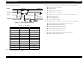
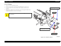
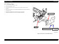
1.3.4 Buzzer
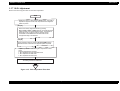
1.3.5 Default Setting
This printer has the buzzer to indicate its current condition with the following
indications.
You can change some parameters that the printer refers to at printer initialization.
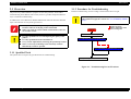
1.3.5.1 Setting Method
The symbols used in the table above represent the following:
Refer to the following flowchart for default setting.
“•” Short Beep (Beeper sounds about 100 ms and interval is about100 ms)
“-”
Long Beep (Beeper sounds about 500 ms and interval is about100 ms)
Finish?
START
Table 1-37. Buzzer Status
Printer status
Paper out error
Beep sounds
•••
Release lever operation error
•••
Cover open error
•••
Paper eject error
•••
Panel operation
•
Fatal error *1
NO
Press Set (Tear Off/Bin)
button.
Holding down Item ↓ (Font)
button, turn the printer on.
The select sheet will be
printed.
Language selection sheet.
Change the
language?
-----
YES
Press Item ↓ (Font) button to
select the aimed language.
NO
Note “*1”: The printer detects various type of “Fatal Error” condition and a type of error is
memorized in EEPROM of the main controller board. Refer to Chapter-3: 3.2.12
Fatal Error for details.
YES
Press Set (Tear Off/Bin)
button.
The current setting value
and the language that was
selected will be printed.
Referring to Font LEDs,
press Item ↓ (Font) or Item
↑ (Pitch) button to select
the menu.
Referring to Pitch LEDs,
press Set (Tear Off/Bin)
button to change the setting
value.
Finish?
NO
YES
Press Menu (Pitch & Tear
Off/Bin) button. *
* The printer will exit from the default setting mode after storing
the setting into non-volatile memory.
END
Figure 1-14. Flowchart for Default Setting
PRODUCT DESCRIPTIONS
Operation
33
EPSON FX-890/2190
Revision B
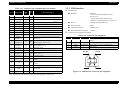
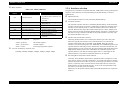
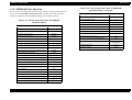
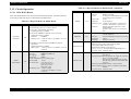
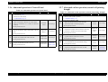
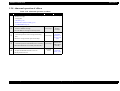
1.3.5.2 Setting Items
Table 1-38. Setting Values Available in Default Setting Mode (continued)
Setting values available for default setting and factory settings are as shown in the table
below:
Table 1-38. Setting Values Available in Default Setting Mode
Item
Page length for front tractor
Page length for rear tractor
3inch, 3.5inch, 4inch, 5.5inch, 6inch, 7inch, 8inch, 8.5inch,
11inch, 70/6inch, 12inch, 14inch, 17inch
Skip over perforation
OFF, ON
Auto tear off
OFF, ON
Auto line feed
OFF, ON
Print direction
Bi-D, Uni-D
Software
ESC/P, IBM PPDS
0 slash
0, ∅
I/F mode
Auto, Parallel, USB, Option
Auto I/F wait time
10 seconds., 30 seconds.
Buzzer
OFF, ON
Auto CR ( IBM PPDS)*1
IBM character
Setting / Value *2
3inch, 3.5inch, 4inch, 5.5inch, 6inch, 7inch, 8inch, 8.5inch,
11inch, 70/6inch, 12inch, 14inch, 17inch
Setting / Value *2
Item
table*1
OFF, ON
Table 2, Table 1
Note “*1”: This setting is effective when IBM PPDS emulation is selected.
“*2” : Settings with bold weight mean the standard factory settings.
Parallel I/F bidirectional time OFF, ON
Packet mode
Auto, OFF
Character table
Standard version:
Italic, PC437, PC850, PC860, PC863, PC865, PC861,
BRASCII, Abicomp, Roman 8, ISO Latin 1, PC 858, ISO
8859-15
NLSP version:
Italic, PC437, PC850, PC437 Greek, PC 853, PC855, PC852,
PC857, PC866, PC869, MOZOWIA, Code MJK, ISO 8859-7,
ISO Latin 1T, Bulgaria, PC774, Estonia, ISO 8859-2, PC866
LAT., PC866UKR, PCAPTEC, PC708, PC720, PC AR864,
PC860, PC865, PC861, PC 863, BRASCII, Abicomp,
Roman8, ISO Latin 1, PC858, ISO8859-15, PC771, PC437
Slovenia, PC MC, PC 1250, PC 1251
International character set for Italic U.S.A., Italic France, Italic Germany, Italic U.K., Italic
Italic table
Denmark 1, Italic Sweden, Italic Italy, Italic Spain 1
Manual feed wait time
1 second, 1.5 seconds, 2 seconds, 3 seconds
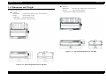
PRODUCT DESCRIPTIONS
Operation
34
EPSON FX-890/2190
Revision B
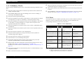
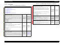
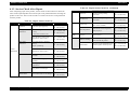
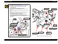
1.3.6 EEPROM Clear Function
Table 1-39. Cleared Items and Values on EEPROM
(Standard Model) (continued)
You can return some parameters into the factory settings to perform panel operation
easily. Pressing Load/Eject & LF/FF & Pause switches at the same time while
turning on the printer returns the default settings into the factory settings:
Item
Buzzer
Auto CR
Tear-off adjustment value
Table 1-39. Cleared Items and Values on EEPROM
(Standard Model)
Tear-off wait time
TOF minimum value
Value
On
Off
0
3 sec.
4.2 mm
Item
Character table selection
Value
PC437
Page length for rear tractor
11 inch
Paper length for rear manual insertion
22 inch
Page length for front tractor
11 inch
Paper length for front manual insertion
22 inch
Page length for CSF bin 1
22 inch
Sub number for customization
Standard
Page length for CSF bin 2
22 inch
Parallel I/F bidirectional mode
On
TOF adjustment value for rear tractor
8.5 mm
Packet mode for Parallel I/F (IEEE1284.4)
TOF adjustment value for front tractor
8.5 mm
TOF adjustment value for CSF bin 1
8.5 mm
TOF adjustment value for CSF bin 2
8.5 mm
TOF adjustment value for rear manual insertion
8.5 mm
TOF adjustment value for front manual insertion
8.5 mm
Bottom margin for rear tractor
11 inch
Bottom margin for front tractor
11 inch
Font Selection
Draft
Pitch selection
10cpi
Print direction setting
Bi-d
I/F mode selection
Auto
Auto I/F waiting time setting
Auto line feed
Off
Off
Skip over perforation
Off
Input buffer
On
0 slash
PRODUCT DESCRIPTIONS
Packet mode for USB (IEEE1284.4)
0
Auto
same as ‘IEEE 1284.4
for Parallel I/F‘
Manual feed wait time
1.5 sec.
IBM character table
Table2
10 sec.
Auto tear off
Software
Paper edge length
ESC/P
Off
Operation
35
EPSON FX-890/2190
Revision B
1.3.7 Bi-D Adjustment
Refer to the following flowchart for the Bi-D adjustment.
start
Turning the printer on while pressing Pause switch. The guide to
adjust Bi-d. alignment in this mode is printed and first alignment
pattern is printed.
[ Step A ]
Select most closely alignment number by pressing
Item ↓ (Font) and Item ↑ (Pitch) switches. Font LEDs show the
pattern number which is selected at that time. The selestion is
advanced one by one as the switch is pressed, and the
combination of On/Off/Blink of those three LEDs is also
changed according to the selection.
[ Step B ]
Fix the selected number by pressing Set (Tear Off/Bin) switch.
Selected number is fixed and next alignment pattern is printed.
Repeat Steps A and B until finishing Bi-d. adjustment for NLQ
mode.
Following adjustment is executed.
1. Bi-d. adjustment for high speed draft mode
2. Bi-d. adjustment for draft mode
3. Bi-d. adjustment for NLQ mode
Turn the printer off.
The setting is stored into EEPROM.
END
Figure 1-15. Bi-D Adjustment Flowchart
PRODUCT DESCRIPTIONS
Operation
36
EPSON FX-890/2190
Revision B
1.4 Dimensions and Weight
Physical specifications
Dimensions:
Weight:
589 mm (W) x 350mm (D) x 167.5mm (H) *
Approximately TBD kg
* This measure excludes “the protrusions.”
FX-890
Dimensions:
Weight:
Appearance:
FX-2190
414 mm (W) x 350 mm (D) x 167.5 mm (H) *
Approximately 7.6 kg
See the figures below.
* This measure excludes “the protrusions.”
Figure 1-17. Physical Specifications for FX-2190
Figure 1-16. Physical Specifications for FX-890
PRODUCT DESCRIPTIONS
Dimensions and Weight
37
EPSON FX-890/2190
Revision B
Physical specifications including High capacity cut sheet feeder (Bin1)
FX-2190
Dimensions:
Weight:
FX-890
Dimensions:
Weight:
Appearance:
414 mm (W) x 434 mm (D) x 378 mm (H) *
Approximately 8.9 kg
See the figures below.
589mm (W) x 434mm (D) x 378mm (H) *
Approximately TBD kg
* This measure excludes “the protrusions.”
* This measure excludes “the protrusions.”
Figure 1-19. Physical Specifications including High capacity cut sheet
feeder (Bin 1) for FX-2190
Figure 1-18. Physical Specifications including High capacity cut sheet
feeder (Bin 1) for FX-890
PRODUCT DESCRIPTIONS
Dimensions and Weight
38
EPSON FX-890/2190
Revision B
Physical specifications including Single bin cut sheet feeder (Bin2)
FX-2190
Dimensions:
Weight:
FX-890
Dimensions:
Weight:
Appearance:
414 mm (W) x 445 mm (D) x 386 mm (H) *
Approximately 8.2 kg
See the figures below.
589mm (W) x 445mm (D) x 386mm (H) *
Approximately TBD kg
* This measure excludes “the protrusions.”
* This measure excludes “the protrusions.”
Figure 1-21. Physical Specifications including Single bin cut sheet feeder
(Bin 2) for FX-2190
Figure 1-20. Physical Specifications including Single bin cut sheet feeder
(Bin 2) for FX-890
PRODUCT DESCRIPTIONS
Dimensions and Weight
39
EPSON FX-890/2190
Revision B
Physical specifications including High capacity cut sheet feeder (Bin) & Single
bin cut sheet feeder (Bin2)
Dimensions:
Weight:
FX-890
Dimensions:
Weight:
Appearance:
FX-2190
414 mm (W) x 564 mm (D) x 408 mm (H) *
Approximately 9.5 kg
See the figures below.
589mm (W) x 564mm (D) x 408mm (H) *
Approximately TBD kg
* This measure excludes “the protrusions.”
Figure 1-23. Physical Specifications including High capacity cut sheet
feeder (Bin1) & Single bin cut sheet feeder (Bin 2) for FX-2190
Figure 1-22. Physical Specifications including High capacity cut sheet
feeder (Bin1) & Single bin cut sheet feeder (Bin 2) for FX-890
PRODUCT DESCRIPTIONS
Dimensions and Weight
40
EPSON FX-890/2190
Revision B
FX-880T+ (=ML320T) mode is different from “current FX-890” mode in the
1.4.1 FX-880T+ Mode
C A U T IO N
following features:
This function may be used only on the models intended for EAI
market. On any model intended for any other market, do not
execute the command to enter this mode.
Supports commands similar to ML320T
Adds some default setting items similar to ML320T
Supports printer defaults similar to ML320T
Action of the printer is similar to ML320T
This printer has FX-880T+ mode which supports not only OKI ML command but also
ML320T’s defaults.
You can switch printer mode from current FX-890 to FX-880T+ (=ML320T) in the
following way on FX-890. Also FX-2190 can set FX-880T+ mode.
1.4.1.2 Supported commands
FX-880T+ (=ML320T) mode supports ESC/P, IBM and OKI ML320T commands.
NOTE: “Remote commands” should not be used in FX-880T+ mode.
1.4.1.1 Setting of FX-880T+ mode
To change mode from “current FX-890” to “FX-880T+ (=ML320T)” or vice
versa:
Turn the printer on while pressing both of “Tear Off/Bin” and “Pause” buttons.
The following commands are available in any command emulation mode (ESC/P,
IBM, OKI ML320T)
ESC { n
emulation change
ESC } Nul
software I-Prime
In ESC/P command emulation, if the following commands come, printer ignores
them.
ESC ( Nul
ESC X m n1 n2
In IBM command emulation, if the following commands come, printer ignores
them.
Turn the printer on while pressing both
of “Tear Off/Bin” & “Pause” buttons
C H E C K
P O IN T
ESC V Nul
ESC % H
When the printer starts in the newly set mode, it beeps one
time or two times depending on the new mode.
FX890 →
FX-880T+ : 1 time
FX-880T+ → FX890
: 2 times
When the printer starts in the newly set mode, the new setting
is saved into EEPROM.
At this point, the other setting contents of EEPROM are
initialized.
PRODUCT DESCRIPTIONS
Dimensions and Weight
41
EPSON FX-890/2190
Revision B
1.4.1.3 Default setting items
1.4.1.5 Action of the printer
Table 1-40. Setting Values Available for Default Setting Mode
Item
Setting / Value
ESC/P, IBM PPDS, OKI ML320T
*IBM PPDS is the same as IBM 238x plus.
Software
Interface
FX-880T+ mode does not have Device ID.
Only Parallel I/F is possible use. (Can not use USB I/F and Optional Type-B I/F)
Tear Off
Auto tear Off Wait Time
0.5 second, 1 second, 2 seconds, others
Bottom margin
4.2 mm, 20 mm, 22 mm, 24 mm, others
*When “24 mm” is selected, the printer acts with approx.23.5 mm
Line Spacing
6LPI, 8LPI
Paper Out Override
OFF (No), ON (Yes)
When the Tear Off button is pushed, the printer sends the present printing position
in the Tear Off position.
If the Auto Tear Off setting is On, the printer always do the Tear Off action when
it is not printing.
TOF position (MicroAdjust)
The setting range of Micro Adjust is 4.2mm to 22mm to 558.8mm(22inch).
NOTE: * Don’t set up TOF more largely than Page length.
Note : Settings with bold weight mean the default setting.
1.4.1.4 Printer defaults
FX-880T+ mode has different defaults from current FX-890 mode as follows.
N
Table 1-41.
Items
Current FX-890
ESC/P
FX-880T+ (=ML320T)
IBM PPDS (*)
Top margin
4.2 mm
22.5 mm
Bottom margin
4.2 mm
24 mm
Auto tear Off Wait Time
3.0 sec.
0.5 sec.
Software
Note “*” : IBM PPDS is same as IBM 238x plus.
PRODUCT DESCRIPTIONS
Dimensions and Weight
42
2
CHAPTER
OPERATING PRINCIPLES
EPSON FX-890/2190
Revision B
2.1 Overview
C524 PSB/PSE/PSH Board
This printer is divided into several main components for easy removal and repair. The
main components are:
C524MAIN:
Control board
C524PSB/PSE/PSH:
Power supply board
C524PNL:
Operation panel board
Printer mechanism:
Printhead, Carriage, Ribbon mechanism, Platen
gap adjustment mechanism, Paper feed
mechanism, Release mechanism
Housing:
Upper case, Lower case, Rear sheet guide,
Knob, Printer cover
The C524 PSB/PSE/PSH power supply board consists of Transformer, Switching FET,
Regulator IC, Diode bridge, Fuse, Photo-coupler, and so on.
CN1
Photo-coupler
Switching FET
Transformer
C524MAIN Board
CN2
The C524MAIN board consists of 2in1ASIC(CPU), EEPROM, PROM, DRAM,
PF Motor Driver IC, CR Motor Driver IC driver elements, and so on.
CR Motor Driver IC
PF Motor Driver IC
Diode Bridge
Figure 2-2. C524 PSB/PSE/PSH Component
2in1ASIC
E01A29CA
PROM
Print Head
Driver
EEPROM
DRAM
Figure 2-1. C524MAIN Component
Operating Principles
Overview
44
EPSON FX-890/2190
Revision B
2.1.1 Printer Mechanism
2.1.1.2 Paper Feed Mechanism
This printer mechanism consists of Printhead, Paper feed mechanism, Carriage
movement mechanism, Tractor feed mechanism, Platen gap adjustment mechanism,
Ribbon feed mechanism, PF motor, CR motor, detectors, and so on.
The paper feed mechanism picks up paper and transports it to the printhead, then ejects
the paper step by step or continuously driven by the PF motor. PF motor drives the
paper feed mechanism gears and the platen roller. The top of form and paper out
condition are detected by the front and rear PE detectors, respectively.
2.1.1.1 Printhead
The printhead prints data from the control board on paper using the ink ribbon. The
printhead is mounted on the carriage unit.
Printing method:
Impact dot matrix printing
Number of dot wires:
18
Diameter of dot wire:
φ0.29 mm
Dot wire arrangement:
2.1.1.3 Carriage Movement Mechanism
The carriage movement mechanism carries the carriage unit left and right along the CR
guide shaft and mechanism frame, and stops it at any position for printing. It is driven
by torque sent from the CR motor via the timing belt. Home position is detected by the
HP (home position) detector at power on and at CR motor phase change.
2.1.1.4 Tractor Feed Mechanism
The tractor feed mechanism feeds continuous paper to the printhead and ejects it.
Torque from the PF motor is transferred to the tractor unit via the release mechanism in
the paper feed mechanism. The release lever in the release mechanism switches torque
from the PF motor between cut sheet feeding and continuous paper feeding. This
printer is equipped with several tractor feeding methods (front / rear push tractor
feeding, front / rear push & pull tractor feeding and front / rear pull tractor feeding),
which is selected according to the tractor unit setting positions and the lever positions.
The tractor detector detects the release lever setting position, for cut sheet feeding or
continuous paper feeding.
2.1.1.5 Platen Gap Adjustment Mechanism
Figure 2-3. Dot Wire Arrangement
Operating Principles
The platen gap (the gap between the platen and the printhead) adjustment mechanism
consists of the CR guide shaft, parallelism adjustment bushing, PG adjust lever and PG
detector. The PG adjust lever is attached to the left side of the CR guide shaft. The
bushing is attached to the left frame. Since the CR guide shaft is eccentric, the
printhead approaches or recedes from the platen roller as the PG lever turns forward or
backward. The PG detector detects the PG lever position. If the lever is set to a position
between “2” and “6”, the printer is in the copy mode.
Overview
45
EPSON FX-890/2190
Revision B
2.1.1.6 Ribbon Feed Mechanism
2.1.1.7 Sensors
The CR motor drives the ribbon feed mechanism via the timing belt. The ribbon feed
mechanism has the sun and planetary gear system. No matter the carriage unit is driven
left and right, the ink ribbon is driven in one direction.
Table below lists the sensors of this printer.
Tractor
PG
Detector
Table 2-1. Sensors
Sensor
PF Motor
Rear PE Detector
Release Lever
CR HP detection
Outline
Means
Switch rating
Switch mode
Platen Roller
Front PE detector
PE detection
(Front)
CR Guide Shaft
PE detection
(Rear)
Printhead
Timing Belt
CR Motor
PG Adjust
Lever
HP Detector
Carriage Unit
Platen Gap
detection
Release Detector
Ribbon Unit
Release Lever
detection
Figure 2-4. Printer Mechanism Outline
Operating Principles
Cover open
detection
Overview
Means
Switch rating
Switch mode
Means
Switch rating
Switch mode
Means
Switch rating
Switch mode
Means
Switch rating
Switch mode
Means
Switch rating
Switch mode
Refer to for
Disassembly/
Assembly
Mechanical contact
06~1.0 mA 5 VDC ± 5%
(Resistance load)
Within home (IN): CLOSE
Out of home (OUT): OPEN
p.78
Mechanical contact
06~1.0 mA 5 VDC ± 5%
(Resistance load)
There is paper: OPEN
No paper: CLOSE
p.87
Photo interrupter
5 VDC ± 5%
(Resistance load)
There is paper: OPEN
No paper: CLOSE
p.87
Mechanical contact
06~1.0 mA 5 VDC ± 5%
(Resistance load)
Normal mode (0~1): CLOSE
Copy mode (2~7): OPEN
p.86
Mechanical contact
06~1.0 mA 5 VDC ± 5%
(Resistance load)
Friction: OPEN
Tractor: CLOSE
p.86
Mechanical contact
06~1.0 mA 5 VDC ± 5%
(Resistance load)
Case opened: OPEN
Case closed: CLOSE
p.72
46
EPSON FX-890/2190
Revision B
2.1.2 Circuit Operation
Table 2-2. Major Elements on MAIN Board (continued)
Elements
Location
2.1.2.1 C524 MAIN Board
Use:
Device:
Type:
The C524 MAIN board is the control circuit board of this printer. This board consists
of several IC chips and drivers, as described in the table below:
Table 2-2. Major Elements on MAIN Board
Elements
Location
DRAM
IC5
Function
Package:
240 SQFP (0.5 mm between pins)
Manufacturing process: 0.35µ Cell base IC
CPU (H8S/2670 (Hitachi) equivalent)
CPU/ASIC
(2in1ASIC)
PROM
(Flash ROM)
IC1
IC4
Operating Principles
Function
• Operating frequency: 24 MHz
I/F section (E05B80CC (Hitachi series) equivalent)
• Operating frequency: 48 MHz
• Function:
E05B80C
• Memory cycle: 3 states (1 state 41.7 ns, RDNn = 0, no CS
assertion)
Mechanical Controller section (E05B85YA (Fujimi)
equivalent)
• Operating frequency: 24 MHz
• Memory cycle: 3 states (1 state 41.7 ns, RDNn = 0, no CS
assertion)
Various buffers, work areas
MSM51V18165D
2CAS type 16-Mbit DRAM of access time
60 ns with page access function
Bus width:
16 bits
Package:
50-pin TSOP II
Memory cycle: 4 states at normal times (1 state 50.6 ns)
2 states in burst mode (1 state 50.6 ns)
Refresh:
Refresh controller of the CPU is used
(CBR method)
Period: 1,024 cycles/16 ms (15.625 us or
less)
Use:
EEPROM
Parallel IF circuit
Use:
Program
Type:
MBM29LV800BA-90
Capacity:
8Mbit
Package:
44SOP
Bit configuration: 8/16 switching type
Bus width:
16 bits
Access time:
tCE 181 ns or less
tACC 181 ns or less
tOE 156 ns or less
tDF 60 ns or less
Memory cycle: 3 states 1 weight
(1 state 50.6 ns, RDNn = 0, no CS
assertion)
IC11
Device:
Capacity:
Package:
Storage of default setting values and
various parameters
S-93C46ADFJ (SII) (10 ms/word writing)
1 kbits
SOP8 pin (150 mil)
Specification: IEEE1284 compliant Nibble
Data receiving system: Data transfer by DMA
ACK pulse width: Can be selected
Data transfer timing: Can be selected
Transceiver IC: 74LVX161284 (FAIRCHILD) (IC2)
Control circuit: Inside the ASIC
Specification:
USB IF circuit
Overview
Universal Serial Bus Specification
Revision 1.1
Reception mode:Full speed mode (D+ signal line is pulled
up to +3.3V with 1.5 kΩ)
Pull-up of D+ signal line is not activated
until the logic system becomes stable after
power on.
Receiving system: Bulk transfer / control transfer
Data reception capacity: About 1.15 MB/s at peak (Bulk
transfer)
Control circuit: Inside the ASIC
47
EPSON FX-890/2190
Revision B
Table 2-2. Major Elements on MAIN Board (continued)
Elements
Location
Table 2-2. Major Elements on MAIN Board (continued)
Function
Elements
Level 2
Current consumption 0.5 A max.
SSI is supported.
Transmission rates supported are 600/1200/2400/4800/
9600/19200 [bps].
Data reception rate (between TYPE B and Main Circuit
Board) is 2 MB/s at peak.
Data receiving system: DMA
Data reception timing: Based on TYPE-B specification
Location
Specification:
TYPE-B IF circuit
RESET IC
IC13
Oscillating circuit
Drive voltage: 42 V ± 5%
Drive IC:
SLA7024M (Sanken)
Drive system: Constant-current unipolar drive
Excitation method: 2-2 phase /1-2 phase (quadrangular) /1-2
phase (circular) /W1-2 phase driving
Current detection resistance:0.68 Ω, 2 W
Current value setting:Setting with D/A port of the CPU
D/A reference voltage (= 3.3 ± 0.3 V)
The maximum of 8-bit current setting
register for D/A (= d'255)
Current setting resolution:3.3/255/
0.68=0.019A
QPIT compensation: D/A circuit is compensated to ensure
current accuracy (± 5% at the maximum
current and ± 10% at the minimum
current).
CR Motor Driver
Power ON reset
• Device:
Reset IC LA5623M (Sanyo) equivalent
reset circuit 2
• Detecting voltage: 4.2 ± 0.2 V (logic system)
• Processing:
Generates a hardware reset, and there is
delay of 60 ms (min.) at turning High from
Low.
Power OFF detection
• Device:
Reset IC LA5623M (Sanyo) equivalent
reset circuit 1
• Detecting voltage:1.25 ± 0.05 V (keeps watch on power
system by resistor division)
• Processing:
Divides 42 V source voltage by resistance
at 1.4/30, and keeps watch on.
Generates NMI interrupt request when
42V source voltage is 28.0 V (min. 26.4
V).
IC15
Drive voltage: 42 V± 5%
Drive system: Constant-current bipolar drive
Drive IC:
A3972 (Sanken)
Excitation method:1-2 phase
Phase change: The ASIC generates the control signal of
the drive IC based on the trigger signal
(CPU output).
Current value setting: Setting with D/A converter of drive
IC. Any setting number is available.
Current detection resistance:0.56Ω ± 1%, 1 W
Output at reset: SLEEP signal (G/A output) Low. (Output
current off)
PF Motor Driver
IC9
Element:
Ceramic oscillator
Frequency:
48.00 MHz
Oscillation stabilization time: 10 ms or less
Head Driver
Operating Principles
Function
Overview
QM1,
QM2,
QM3
Drive voltage: 42 V ± 5%
Drive system: Constant voltage drive
Drive Tr:
SMA4037 (Sanken) 3A
Control method: Controlled by ASIC based on print timing
signal (CPU output)
At reset:
G/A output L (head drive off)
QPIT compensation: The voltage detecting circuit is
compensated to ensure the accuracy of
head energization time.
48
EPSON FX-890/2190
Revision B
Table 2-2. Major Elements on MAIN Board (continued)
Elements
Location
Energy save (ESA
VE) circuit
Simple ecodrive
circuit
Function
Driver element: DTC124X
Control:
Controlled by output port (P_CTRL) of ASIC
Register setting
0: 42 V power voltage rising (Power ON)
{At reset}
1: 42 V power voltage lowering
90 V constant voltage circuit:(2 circuits each of which is
constituted with 9 pins)
Type:
Constant-voltage dropper circuit (for head
power regression)
Driver element:FET 2SK3155 (Hitachi)
Input eco voltage:88.7 V ~ 95.8 V
Output power voltage:+42 V ± 5% (Controlled to a constant
voltage by Power Supply Unit.)
Overvoltage detecting circuit (OVP): Detects 120 V or
above as a overvoltage.
Outputs Off signal to the Power Supply Unit.
Figure 2-5. C524 MAIN Block Diagram
Operating Principles
Overview
49
EPSON FX-890/2190
Revision B
2.1.2.2 C524 PSB/PSE/PSH Power Supply Circuit
This printer can be powered by one of the following three power supply boards: the
C524PSB (120 V) board, the C524PSE (230 V) board, or the C524PSH (Universal)
board. The function of the boards is the same, except for a difference in the primary
circuitry. The power supply outputs the DC current necessary to drive the printer
control circuit and drive the mechanism.
INPUT SPECIFICATIONS
Table 2-4. Input Specifications
Power Supply Unit
Name
Rated input power
voltage
Input voltage range
CIRCUIT CONSTITUTION
Rated input power
frequency
Figure 2-6 below shows the block diagram of this power supply circuit.
Input frequency range
Input
current
(Only for
reference
*1)
Input
power
(Only for
reference
*1)
Min. load
ZC-RCC Converter
+5 V Circuit
Chopper circuit with a MOSFET discrete structure
100-120 VAC
220-240 VAC
100-240 VAC
85-138 VAC
187-276 VAC
85-276 VAC
50-60 Hz
47-63 Hz
(100 V, 60 Hz
/240 V, 50 Hz)
0.05 A / 0.05 A
0.05 A / 0.04 A
0.08 A / 0.08 A
Rated load
0.78 A / 0.69 A
0.41 A / 0.39 A
0.78 A / 0.42 A
2.30 A / 1.96 A
1.18 A / 1.10 A
2.34 A / 1.18 A
(100 V, 60 Hz
/240 V, 50 Hz)
(100 V/120 V, 60 Hz) (220 V/240 V, 50 Hz)
Min. load
2.1 W / 2.3 W
2.2 W / 1.6 W
3.6 W / 2.1 W
Rated load
45.5 W / 45.2 W
45.4 W / 45.4 W
47.1 W / 46.8 W
Max. load
153.3 W / 148.6 W
147.9 W / 146.7 W
159.7 W / 152.2 W
40 A (0-p) or less
(Input: 138 V/60 Hz)
40 A (0-p) or less
(Input: 276 V/50 Hz)
40 A (0-p) or less
(Input: 276 V/50 Hz)
(Ambient temperature: 25°C, At cold start)
Table 2-3. Circuit Constitution
42 V zero cross RCC of high performance
Constant-voltage detecting circuit of Tr+ZD type
Low power standby mode function by the ESAVE signal is
C524 PSH
(100-240V Spec)
Max. load
Inrush current
Description
Inrush current preventive circuit with a power thermistor
C524 PSE
(220-240V Spec)
(100 V / 120 V, 60 Hz) (220 V / 240 V, 50 Hz)
Figure 2-6. Power Supply Circuit Block Diagram
Block
Input Filter
C524 PSB
(100-120V Spec)
Leak current
0.25 mA or less
(Input: 100 V / 50 Hz)
0.75 mA or less
0.75 mA or less
0.75 mA or less
(Input: 138 V / 60 Hz) (Input: 276 V / 60 Hz)
(Input: 276 V / 60 Hz)
(Ambient temperature: 25°C)
supported
43 ms or more
Output holding time
(Input: 85 V/47 Hz)
(Input: 187 V/47 Hz)
(Input: 85 V/47 Hz)
(Output: Rated load/Ambient temperature: 25°C
Operating Principles
Overview
50
EPSON FX-890/2190
Revision B
Table 2-4. Input Specifications
Power Supply Unit
Name
Special output holding
time
(The period from the
time when output 1 has
dropped below 26 V to
the time when output 2
drops below the output
voltage lower limit)
PROTECTIVE FUNCTIONS
C524 PSB
(100-120V Spec)
C524 PSE
(220-240V Spec)
120 ms or more
C524 PSH
(100-240V Spec)
(Input: 85 V, 60 Hz)
(Input: 187 V, 50 Hz)
(Input: 85 V, 60 Hz)
Table 2-6. Protective Functions
(Output: At output 1 of no-load and output 2 of rated load)
Item
Overcurrent protection (OCP)
Output 1
Dropping + cutoff
Output 2
Cutoff
OCP reset method
Turning power off
once and on again
Turning power off
once and on again
0A
0A
Overvoltage protection (OVP)
Cutoff type
Cutoff type
OVP preset voltage
45 ~ 58 V
6~9V
Load short-circuit current
Note “*1”: Each value indicated here is only the average of measured values of samples
(sample size n = 3), that is, it is not a typical value or guaranteed value.
“*2” : Each value does not include the current flowing in the capacitor of the EMI filter
circuit.
OUTPUT SPECIFICATIONS
Table 2-5. Output Specifications
Item
Rated output voltage
Output voltage fluctuation *1
Rated output current
Output current at startup *2
Output current range
Output 1
+42 V
Output 2
+5 V
40.0 ~ 44.0 V
4.75 ~ 5.25 V
0.8 A
0.7 A
0A
0.7 A
0~2.8 A
0~0.7 A
Ripple voltage *3
-----
100 mVpp Typ.
Spike voltage *3
1500 mVpp Typ.
300 mVpp Typ.
Note “*1”: Neither Output 1 nor Output 2 includes the spike voltage component.
“*2” : The output current during power supply startup must be not greater than the value
specified above.
“*3” : The values for ripple and spike voltage indicated above, which are the values with a
rated resistance load, are only for reference. (Ambient temperature: 25°C)
For measurement, connect a KMF50V470µF electrolytic capacitor and 0.1 µF film
capacitor to the output 1 terminal, and a KME16V47µF electrolytic capacitor and
0.1µF film capacitor to the output 2 terminal.
Operating Principles
Overview
51
3
CHAPTER
TROUBLESHOOTING
EPSON FX-890/2190
Revision B
3.1 Overview
3.1.2 Procedure for Troubleshooting
Perform troubleshooting work according to the flowchart shown at right.
The printer may exhibit different symptoms for the same problem, which makes
troubleshooting more difficult. This section, however, provides simple and effective
ways to facilitate troubleshooting.
C A U T IO N
In addition, the User's Manual for EPSON EPSON FX-890/2190 describes detailed
steps to be taken for recovery from typical errors.
W A R N IN G
Before starting disassembly and assembly work, read and
understand thoroughly the contents of 3.1.3 “Preliminary Checks
(p.54)” .
When you disassemble the printer, pull the power cable and the
interface cable out of the plug socket beforehand.
When you touch any surface which can become hot, take care
not to suffer a burn.
Broken line arrow:
Refer to depending on the
result of diagnosis
START
3.1.3 Preliminary Checks (p.54)
C A U T IO N
Use only specified tools to avoid impairing the quality of the
printer.
Use only specified lubricants and adhesives.
Carry out the adjustment by following the specified procedure.
Wear a wrist strap to discharge static electricity from the
human body, whenever possible.
3.2 Troubleshooting Based on Symptoms (p.55)
3.3 Troubleshooting for Individual Units (p.64)
3.1.1 Specified Tools
This printer does not require any specified tools for troubleshooting.
Adjustment (p.93) and Maintenance (p.98)
Figure 3-1. Troubleshooting Process Flowchart
Troubleshooting
Overview
53
EPSON FX-890/2190
Revision B
3.1.3 Preliminary Checks
Make sure that gears of the printer mechanism do not rub each other excessively.
Before starting troubleshooting, be sure to verify that the following conditions are all
met:
Make certain that the rollers inside the printer are free from soiling and free from
Confirm that all gears are engaged properly.
The power supply voltage must be within the specification limits. (Measure the
scratches.
Clear EEPROM to return the internal settings of the printer to the factory default
voltage at the wall socket.)
settings, if necessary. (Refer to “EEPROM Clear Function” on page -35.)
The POWER CORD must be free from damage, short circuit or breakage, or
miswiring in the POWER CORD.
The printer must be grounded properly.
The printer should not be located in a place where it can be exposed to too high or
low temperature, too high or low humidity, or abrupt temperature change.
The printer should not be located near waterworks, near humidifiers, near heaters
or near flames, in a dusty atmosphere or in a place where the printer can be
exposed to blast from an air conditioner.
3.1.4 Error
As this printer checks its condition by itself at power-on, when it finds any trouble, it
indicates it with error indication buzzer and LEDs. The error indications and
corresponding remedies are shown in the table below:
Table 3-1. Error Indications
The printer should not be located in a place where volatile or inflammable gases
Error
are produced.
The printer should not be located in a place where it can be exposed to direct rays
of the sun.
Beep
sounds
When printer fails to load
Set paper in the printer
a sheet, it goes into paper
correctly.
out error.
Release lever operation error
•••
When release lever
position is wrong, printer
goes into release lever
error.
Set the release lever in the
correct position.
Cover open error
•••
When printer’s cover is
open, printer goes into
cover open error.
Close the cover.
Paper eject error
•••
When printer fails to eject
Remove the jammed paper
a sheet, it goes into paper
from inside the printer.
out error.
-----
Turn off the printer once
A failure related to certain and turn it back on, to see
components is detected.
if the same error occurs
again..
inclination larger than 5 degrees).
The paper used must conform to the specification.
There must be no error in handling of the printer.
The Regular Replacement Parts must have been replaced every time their
respective specified numbers of sheets had been printed.
When printing can not be performed, execute self testing and check to see if any
trouble occurs. (Refer to “Operations at Power-on” on page -31.)
In addition, check the values for “Default Setting”. (Refer to “Default Setting” on
page -33.)
Check to see if the surface or the inside of the printer is soiled remarkably or if any
component is broken.
Make certain that the harness is connected properly.
Troubleshooting
Remedy
•••
Paper out error
The printer must be located in a well-ventilated place.
The printer must be placed on a strong and steady level table (without an
Cause
Fatal error
Note : The symbols used in the table above represent the following:
“•”: Beeper sounds about 100 ms and interval is about100 ms
“-”:Beeper sounds about 500 ms and interval is about100 ms
Overview
54
EPSON FX-890/2190
Revision B
3.2 Troubleshooting Based on Symptoms
3.2.1 Printer fails to operate when power is turned on
You can identify the defective component from the symptom displayed. Table 3-2
below lists the symptoms for various failures so that you can easily identify the
problem. Based on the symptom as mentioned below, identify the problem and take a
remedy by following the appropriate troubleshooting procedure given in Table 3-3 to
Table 3-13.
Table 3-3. Printer fails to operate when power is turned on
Step
Printer fails to operate
when power is turned on
Abnormal carriage
operation at power on.
Problem
Refer to
Printer mechanism does not operate.
p.55
No LED on control panel lights up.
p.56
Carriage moves away from the home position at
power on.
Carriage returns to home position correctly, but the
printer then fails to enter the READY mode.
p.56
No
1
Fuse
Check the electric circuit and printer mechanism,
and if they are not short-circuitted, replace the fuse
with a new one.
Problem
solved
Go to Step 2
Problem
solved
Go to Step 3
Replace the
CR HP
Detector.
Go to Step 4
Replace the
CR Motor.
Go to Step 5
Replace the PF
Motor.
Go to Step 6
Replace the
Power Supply
Board.
Go to Step 7
Replace the
Main Board.
Go to 3.2.11
Electrical
Noise (p.62)
♦Is the problem solved?
Printing is faulty during
self-test, but carriage
operation is normal.
No printing at all. Faulty printing. Some dots are
missing from print.
p.58
Abnormal paper feeding
The printer prints but does not feed paper properly.
p.57
Abnormal operation of
Control Panel
• Faulty LED indication
• Input through switches impossible
p.59
Data sent from the host
computer is not printed
properly.
Carriage operates normally at power on, and self-test
is executed correctly, but data is not printed. Data
from the computer is not printed properly.
p.59
Abnormal operation of
ribbon
• Defective ribbon cartridge
• Defective ribbon feed mechanism
p.60
Abnormal operation of
Carriage Unit
Printer mechanism does not operate.
p.60
Faulty print
Printer mechanism operates, but print is faulty.
Printer goes into fatal
error status when power is
turned on.
• “Fatal error” is displayed on the control panel.
• After initialization operation, the printer goes into
error status.
2
Connection with connectors
Make sure that the connectors on the Main Board
are connected properly.
♦Is the problem solved?
3
Defective CR HP Detector
Replace the CR HP Detector with a new one.
♦Is the problem solved?
4
Defective CR Motor
Replace the CR Motor with a new one.
5
Defective PF Motor
Replace the PF Motor with a new one.
♦Is the problem solved?
♦Is the problem solved?
p.62
p.63
6
Power Supply Board
Replace the Power Supply Board with a new one.
♦Is the problem solved?
7
Main Board
Replace the Main Board with a new one.
♦Is the problem solved?
Troubleshooting
Yes
Parts below can be the source of this error (Chapter 4 Disassembly and Assembly)
• Fuse
• HP (Home Position) Detector (p.78)
• CR Motor (p.81)
• PF Motor (p.83)
• C524MAIN Board (p.74)
• C524PSB/PSE/PSH Board (p.76)
Table 3-2. Symptoms and Problems
Symptom
Action and Question
Troubleshooting Based on Symptoms
55
EPSON FX-890/2190
Revision B
3.2.2 No LED on Control Panel lights up even with power
turned on
Table 3-4. No LED on Control Panel lights up
Step
Action and Question
Yes
No
Parts below can be the source of this error (Chapter 4 Disassembly and Assembly)
• Fuse
• Power Switch
• Control Panel (p.72)
• Harness of Control Panel
• C524MAIN Board (p.74)
• C524PSB/PSE/PSH Board (p.76)
1
Fuse
Check the electric circuit and printer mechanism,
and if they are not short-circuitted, replace the fuse
with a new one.
Table 3-4. No LED on Control Panel lights up
Step
6
♦Is the problem solved?
7
2
Go to Step 2
Problem
solved
Go to Step 3
3
4
Problem
solved
5
♦Is the problem solved?
Troubleshooting
Go to Step 7
Replace the
Main Board.
Go to 3.2.11
Electrical
Noise (p.62)
Action and Question
Yes
No
Parts below can be the source of this error (Chapter 4 Disassembly and Assembly)
• HP (Home Position) Detector (p.78)
• Harness of HP Detector
• CR Motor (p.81)
• C524MAIN Board (p.74)
1
Connection with connectors
Make sure that the connectors on the Main Board
are connected properly.
2
Defective CR HP Detector
Replace the CR HP Detector with a new one.
♦Is the problem solved?
Go to Step 4
3
Replace the
harness.
Defective harness of CR HP Detector
Replace the harness of CR HP Detector with a new
one.
♦Is the problem solved?
Go to Step 5
4
♦Is the problem solved?
Control Panel
Replace the Control Panel with a new one.
Replace the
Power Supply
Board.
Problem
solved
Go to Step 2
Replace the
CR HP
Detector.
Go to Step 3
Replace the
harness of CR
HP Detector.
Go to Step 4
Replace the
CR Motor.
Go to Step 5
♦Is the problem solved?
♦Is the problem solved?
Harness of Control Panel
Replace the harness of the Control Panel with a new
one.
No
Table 3-5. Abnormal Carriage operation at power on
Step
Problem
solved
Yes
3.2.3 Abnormal operation of Carriage at power on
♦Is the problem solved?
Connection of harness of Control Panel
Make sure that the connectors of Control Panel ~
Main Circuit Board (CN1 ~ CN20) are connected
properly.
Main Board
Replace the Main Board with a new one.
♦Is the problem solved?
♦Is the problem solved?
Connection with connectors
Make sure that the following connectors are
connected properly:
• Power Supply Board connector (CN1)
• Power Supply Board ~ Main Circuit Board
(CN2~CN14)
Action and Question
Power Supply Board
Replace the Power Supply Board with a new one.
Defective CR Motor
Replace the CR Motor with a new one.
♦Is the problem solved?
Replace the
Control Panel.
Go to Step 6
5
Main Board
Replace the Main Board with a new one.
♦Is the problem solved?
Troubleshooting Based on Symptoms
Replace the
Main Board.
Go to 3.2.11
Electrical
Noise (p.62)
56
EPSON FX-890/2190
Revision B
3.2.4 Abnormal paper feeding
Table 3-6. Abnormal paper feeding
Step
Table 3-6. Abnormal paper feeding
Step
Action and Question
Yes
No
Parts below can be the source of this error (Chapter 4 Disassembly and Assembly)
• Front PE (Paper End) Detector (p.87)
• Harness of Front PE Detector
• Rear PE Detector (p.87)
• Harness of Rear PE Detector
• Release Detector (p.86)
• Harness of Release Detector
• Rear Paper Guide Assembly (p.90)
• PF Motor (p.83)
• PF Gear Train (p.84)
• C524MAIN Board (p.74)
1
Checking for foreign matters
Make sure that there are no foreign matters in the
following areas.
• Paper path
• PF Gear Train
Problem
solved
2
Yes
No
Replace the
defective
harness.
Go to Step 5
Go to Step 6
Check PF
Gear Train
(p.84)
Go to Step 7
Check the
paper feed
mechanism
Replace the PF
Motor.
Go to Step 8
Replace the
Main Board.
Go to 3.2.11
Electrical
Noise (p.62)
♦Is the problem solved?
Paper changeover mechanism
5
♦Is the paper feeding direction switched when you
operate the release lever?
6
Paper feed mechanism
With power turned off, check to see if you can feed
paper by turning the platen knob by hand.
♦Can paper be fed by turning the platen knob by
hand?
Go to Step 2
7
♦Is the problem solved?
Connection of sensor
Make sure that the following sensors are connected
properly:
• Front PE Detector (CN6)
• Rear PE Detector (CN7)
• Release Detector (CN11)
4
Action and Question
Harness of sensor
Replace the defective harness of the following
sensors with a new one:
• Front PE Detector (CN6)
• Rear PE Detector (CN7)
• Release Detector (CN11)
PF Motor
Replace the PF Motor with a new one.
♦Is the problem solved?
8
Problem
solved
Go to Step 3
Replace the
defective
sensors.
Go to Step 4
Main Board
Replace the Main Board with a new one.
♦Is the problem solved?
♦Is the problem solved?
3
Defective sensor
Replace the defective one of the following sensors
with a new one:
• Front PE Detector (CN6)
• Rear PE Detector (CN7)
• Release Detector (CN11)
♦Is the problem solved?
Troubleshooting
Troubleshooting Based on Symptoms
57
EPSON FX-890/2190
Revision B
3.2.5 Printing is faulty during self-test, but carriage
operation is normal
Table 3-7. Printing faulty during self-test, but carriage operation normal
Step
Table 3-7. Printing faulty during self-test, but carriage operation normal
Step
Action and Question
Yes
No
Parts below can be the source of this error (Chapter 4 Disassembly and Assembly)
• Fuse
• Printhead (p.77)
• CR Motor (p.81)
• PF Motor (p.83)
• C524PSB/PSE/PSH Board (p.76)
• C524MAIN Board (p.74)
1
Fuse
Check the electric circuit and printer mechanism,
and if they are not short-circuitted, replace the fuse
with a new one.
Problem
solved
Go to Step 2
Problem
solved
Go to Step 3
Replace the
Printhead.
Go to Step 4
Replace the
CR Motor.
Go to Step 5
5
Action and Question
Defective PF Motor
Replace the PF Motor with a new one.
♦Is the problem solved?
6
Power Supply Board
Replace the Power Supply Board with a new one.
♦Is the problem solved?
7
Main Board
Replace the Main Board with a new one.
♦Is the problem solved?
Yes
No
Replace the PF
Motor.
Go to Step 6
Replace the
Power Supply
Board.
Go to Step 7
Replace the
Main Board.
Go to 3.2.11
Electrical
Noise (p.62)
♦Is the problem solved?
2
Connection with connectors
Make sure that all the connectors on the Main
Circuit Board and Power Supply Board are
connected properly.
♦Is the problem solved?
3
Platen Gap
Adjust the Platen Gap.
♦Is the problem solved?
4
Defective CR Motor
Replace the CR Motor with a new one.
♦Is the problem solved?
Troubleshooting
Troubleshooting Based on Symptoms
58
EPSON FX-890/2190
Revision B
3.2.6 Abnormal operation of Control Panel
3.2.7 Abnormal on-line operation (normal self-printing,
though)
Table 3-8. Abnormal operation of Control Panel
Step
Action and Question
Yes
No
Parts below can be the source of this error (Chapter 4 Disassembly and Assembly)
• Control Panel (p.72)
• Harness of Control Panel
• C524MAIN Board (p.74)
1
Connection of harness of Control Panel
Make sure that the connectors of Control Panel ~
Main Circuit Board (CN1 ~ CN20) are connected
properly.
Problem
solved
Go to Step 2
Table 3-9. Abnormal on-line operation (normal self-printing, though)
Step
1
2
Replace the
harness.
Go to Step 3
2
3
♦Is the problem solved?
4
Main Board
Replace the Main Board with a new one.
♦Is the problem solved?
Replace the
Control Panel.
Replace the
Main Board.
Connection of interface cable
Make sure that the interface cable meets the
specification and is connected properly.
Go to Step 4
Go to 3.2.11
Electrical
Noise (p.62)
Interface cable
Replace the interface cable because the cable may
be defective and thus can cause some trouble.
♦Is the problem solved?
♦Is the problem solved?
Control Panel
Replace the Control Panel with a new one.
3
Firmware
Upgrade firmware to the latest version.
4
EEPROM clearing
Clear EEPROM to restore the default settings.
♦Is the problem solved?
♦Is the problem solved?
5
Main Board
Replace the Main Board with a new one.ÅB
♦Is the problem solved?
Troubleshooting
Yes
No
Problem
solved
Go to Step 2
Replace the
interface
cable.
Go to Step 3
Problem
solved
Go to Step 4
Problem
solved
Go to Step 5
Problem
solved
Go to 3.2.11
Electrical
Noise (p.62)
♦Is the problem solved?
♦Is the problem solved?
Harness of Control Panel
Replace the harness of the Control Panel with a new
one.
Action and Question
Parts below can be the source of this error (Chapter 4 Disassembly and Assembly)
• Interface cable (USB or parallel)
• C524MAIN Board (p.74)
Troubleshooting Based on Symptoms
59
EPSON FX-890/2190
Revision B
3.2.8 Abnormal operation of ribbon
Table 3-10. Abnormal operation of ribbon
Step
Action and Question
Yes
No
Parts below can be the source of this error (Chapter 4 Disassembly and Assembly)
• Ribbon Cartridge
• Timing Belt
• CR Motor (p.81)
• Ribbon Drive (RD) Assembly (p.92)
• C524MAIN Board (p.74)
1
Ribbon Cartridge
Defective Ribbon Cartridge
2
Defective Carriage
Check the operation of the Carriage and Timing
Belt.
Go to Step 2
Replace the
Ribbon
Cartridge.
Go to Step 3
Go to 3.2.9
Abnormal
operation of
Carriage Unit
(p.61)
Go to Step 3
Replace or
lubricate the
Ribbon Drive
Assembly.
Problem
solved
Go to 3.2.11
Electrical
Noise (p.62)
♦Can the Ribbon Cartridge be turned by hand?
♦Does the carriage and belt operate smoothly?
3
4
Defective Ribbon Drive Assembly
Check the operation of the Ribbon Drive Assembly.
♦Does the Ribbon Drive Assembly turn smoothly?
Main Board
Replace the Main Board with a new one.
♦Is the problem solved?
Troubleshooting
Troubleshooting Based on Symptoms
60
EPSON FX-890/2190
Revision B
3.2.9 Abnormal operation of Carriage Unit
Table 3-11. Abnormal operation of Carriage Unit (continued)
Table 3-11. Abnormal operation of Carriage Unit
Step
Action and Question
Yes
No
Parts below can be the source of this error (Chapter 4 Disassembly and Assembly)
• Timing Belt
• CR Motor (p.81)
• HP (Home Position) Detector (p.78)
• Harness of HP Detector
• Ribbon Drive (RD) Assembly (p.92)
• C524MAIN Board (p.74)
1
Checking the connection of connectors
Make sure that the following connectors are
connected properly.
• HP Detector (CN8)
• CR Motor (CN12)
Step
Action and Question
Yes
No
6
Defective harness of HP Detector
Replace the harness of the HP Detector with a new
one.
Replace the
harness of
the HP
Detector.
Go to Step 7
Replace the
CR Motor.
Go to Step 8
Replace the
Main Board.
Go to 3.2.11
Electrical
Noise (p.62)
♦Is the problem solved?
7
Defective CR Motor
Replace the CR Motor with a new one.
♦Is the problem solved?
Main Board
8
Replace the Main Board with a new one.
♦Is the problem solved?
Problem
solved
Go to Step 2
Go to Step 3
Replace the
Timing Belt.
Go to Step 4
Replace or
lubricant the
Ribbon Drive
Assembly.
Go to Step 5
Refer to
Lubrication
(p.100)
Replace the
HP Detector.
Go to Step 6
♦Is the problem solved?
2
Timing Belt
Check to see if the driving path of the Timing Belt
is obstructed with foreign matters or the belt is
damaged.
♦Is the Timing Belt free from obstruction or damage?
3
Ribbon Drive Assembly
Operate the Timing Belt by hand and check the
movement.
♦Does the Timing Belt operate smoothly?
4
Checking the operation of the Carriage Unit
Check to see if you can move the Carriage Unit on
the SHAFT,CR,GUIDE from side to side by hand.
5
Defective HP Detector
Replace the HP Detector with a new one.
♦Does the Carriage Unit operate smoothly?
♦Is the problem solved?
Troubleshooting
Troubleshooting Based on Symptoms
61
EPSON FX-890/2190
Revision B
3.2.10 Faulty print
3.2.11 Electrical Noise
Table 3-12. Faulty print
Step
Action and Question
Table 3-13. Troubleshooting for Electrical Noise
Yes
No
Step
Parts below can be the source of this error (Chapter 4 Disassembly and Assembly)
• Ribbon Mask
• Printhead (p.77)
• Printhead FFC
• C524MAIN Board (p.74)
1
Ribbon Mask
Remove the Ribbon Mask from the Printhead, and
make sure that the Ribbon Mask is free from
deformation or damage.
Problem
solved
Go to Step 2
Defective Printhead
Replace the Printhead with a new one.
Replace the
Printhead.
Go to Step 3
♦Is the problem solved?
3
Platen Gap Adjustment (p.95)
Adjust the platen gap.
♦Is the problem solved?
4
Printhead FFC
Replace the Printhead FFC with a new one.
♦Is the problem solved?
5
Main Board
Replace the Main Board with a new one.
♦Is the problem solved?
Problem
solved
1
Go to Step 4
Go to Step 5
Replace the
Main Board.
Go to 3.2.11
Electrical
Noise (p.62)
No
External noise
1. Check to see if within 3 m from the printer there is
another electrical apparatus, such as a generator,
radio transmitter or an apparatus incorporating a
motor.
2. Turn off the power to the electrical apparatus in
question or move the printer to a position at least 6
m distant from the apparatus.
Go to Step 2
Problem
solved
Go to Step 3
Ask the
customer for
repair of the
AC power
connection.
Go to Step 4
Install the
grounding
screw
properly.
Go to Step 5
Ensure
grounding.
Replace the
Power Supply
Board.
Go to Step 7
Replace the
Main Board.
Problem
solved
♦Does the problem with electrical noise still occur?
2
Replace the
Printhead
FFC.
Yes
Parts below can be the source of this error (Chapter 4 Disassembly and Assembly)
• C524PSB/PSE/PSH Board (p.76)
• C524MAIN Board (p.74)
♦Is the problem solved?
2
Action and Question
AC grounding
Check the AC power connection.
♦Is the AC power cable connected and grounded
properly?
3
Harness of Power Switch
1. Remove the Printer Mechanism. (p.80)
2. Replace the HOUSING ASSY.,LOWER with a new
one.
♦Is the cable grounded properly?
4
Grounding of circuit boards
1. Remove the Shield Cover.(p.74)
2. Make sure that the screws for the Power Supply
Board is tightened securely.
♦Is grounding ensured?
5
Power Supply Board
Replace the Power Supply Board with a new one.
♦Is the problem solved?
6
Main Board
Replace the Main Board with a new one.
♦Is the problem solved?
Troubleshooting
Troubleshooting Based on Symptoms
62
EPSON FX-890/2190
Revision B
3.2.12 Fatal Error
Table 3-14. Troubleshooting for Fatal Error (continued)
Action and Question
Table 3-14. Troubleshooting for Fatal Error
Action and Question
Yes
No
Parts below can be the source of this error (Chapter 4 Disassembly and Assembly)
• C524MAIN Board (p.74)
• C524PSB/PSE/PSH Board (p.76)
• Printhead (p.77)
• CR Motor (p.81)
• PF Motor (p.83)
• HP (Home Position) Detector (p.78)
Abnormal +42V Drive Voltage
(PD Error : value = 37H)
The printer detects abnormal voltage level with +42V line.
Check to see if the components to which +42V is supplied; is
defective (short-circuit).
• Printhead
• CR Motor
• PF Motor
Abnormal CR operation
(CR Error : value = 30H)
CR Home position seek operation is failed, or CR Home
position is detected during printing.
Check to see if one of the following component is defective.
• CR Motor
• Timing belt tension
• CR HP Sensor
CG Access Error
(CG Error : value = 33H)
Failed to access CG, or error in EEPROM data verification.
Check to see if an error solved by replacing the C524MAIN
board.
Troubleshooting
Replace the
defective
component.
Replace the
power supply
circuit board
(C524PSB/
PSE/PSH).
Replace the
defective
component.
Replace
C524MAIN
Board.
Replace
C524MAIN
Board.
Go to 3.2.11
Electrical
Noise (p.62)
Yes
No
Re-connect
FFC or replace
the defective
component.
Replace the
printhead.
Abnormal Printhead TrVce Voltage
(VDD Error : value = 36H)
The level of drive voltage supplied to the printhead is
abnormal.
Replace the
power supply
circuit board
(C524PSB/
PSE/PSH).
Replace the
printhead.
Abnormal voltage with the simple ecodrive circuit
(ECO Error : value = 3CH)
The printer check the operation of simple ecodrive circuit
when it is turned on, and recognizes this error condition if the
voltage level is abnormal.
Replace
C524MAIN
Board.
Replace the
power supply
circuit board
(C524PSB/
PSE/PSH).
Abnormal Printhead Temperature
(Head Open Error : value = 3AH)
The printer actually checks the connection between the
printhead and C524MAIN Board, and an error is recognized
as an abnormal printhead temperature if the connection is
wrong.
Check to see if the connection between the printhead and
C524MAIN Board is correct.
• FFC is not properly connected (or disconnected).
• FFC is damaged.
Troubleshooting Based on Symptoms
63
EPSON FX-890/2190
Revision B
3.3 Troubleshooting for Individual Units
Table 3-16.
F
Common
Line
3.3.1 Main Component Checking Point
Corresponding Wires
R
Common
Line
Corresponding Wires
The following components can be checked with a simple measurement tool, such as a
multi-meter, easily.
C1
1, 7, 13
C5
2, 5, 11
C2
9
C6
3, 15
Motors
C3
10, 18
C7
16, 17
C4
6, 12
C8
4, 8, 14
Table 3-15. Motor Coil Resistance Test Points
Motor
Test Pin Number
Test Method*
Meter
Reading
16.0 Ω ± 10%
(at 25 °C per
one phase)
PF Motor
(CN13)
1 and 3,
2 and 4
Place one lead on pin 1 (pin2) and the other
lead on pin3 (pin 4) on each of the test pins
to check the two motor phases.
CR Motor
(CN12)
Common pin: 5
Test pins: 1, 2, 3
and 4
Place one lead on pin 5 and the other lead on 2.7 Ω±10%
each of the 4 test pins to check the two motor (at 25°C per
phase.
one phase)
Note : 1~18:
Wire numbers (Refer to “Figure 2-3“ in Chapter 2 for wire numbers.)
C1~ C8: Common terminals
T:
Thermistor terminal
N:
Not used
(The contact of the connector and FFC is positioned at the bottom side of the
connector.)
Note “*”: Set the meter to ohms. Then disconnect the Motor from the Main Board and check it
with printer power off.
Printhead
Test Method
: For example, place one lead on pin C1 and the other lead on
Test pin 1 to check #1 pin of the Printhead solenoid. Test
pin numbers match the printhead solenoid (dot wire)
numbers.
NOTE: Set the meter to ohms. Then disconnect the Motor from the Main Board
and check it with printer power off.
Specifications : 8.19 ± 0.8 Ω (at 25°C)
Figure 3-2. Printhead Connector Pin Assignment
Troubleshooting
Troubleshooting for Individual Units
64
4
CHAPTER
DISASSEMBLY AND ASSEMBLY
EPSON FX-890/2190
Revision B
4.1 Overview
4.1.2 Tools and Instruments
This section describes procedures for disassembling and assembling EPSON FX-890/
2190. Unless otherwise specified, disassembled units or components can be reassembled by reversing the disassembly procedure. Therefore, no assembly procedures
are included in this section. Precautions for any disassembly or assembly procedure are
described under the heading “CHECK POINT”. Any adjustments required after
disassembling the units are described under the heading “ADJUSTMENTS”.
The table below lists the tools and the instruments required for disassembling,
assembling or adjusting the printer. Use only tools that meet these specifications.
Table 4-1. Tool and Instrument List
Name
No.2
B743800200
Phillips Screwdriver
No.1
B743800100
Box Driver
7.0mm Diagonal
B741700200
Tweezers
-
B741000100
Round-nose pliers
-
B740400100
Before disassembling, assembling or adjusting the printer,
Thickness gage
-
B776702201
disconnect the power supply cable from the AC power socket.
Failure to do so might cause personal injury.
Be careful with the Printhead when you handle it as it may be
very hot right after printing.
Do not touch the heat sink attached to the switching FET (Q1)
on the power supply board right after power off, as it may be
very hot.
Soldering iron
-
B740200100
E-Ring holder
Size:#6
B740800800
Multi-Meter
OHM/Voltage/Current
-
Oscilloscope
Min. 50MHz
-
Follow the precautions below when disassembling the printer.
C A U T IO N
EPSON Part No.
Phillips Screwdriver
4.1.1 Disassembly Precautions
W A R N IN G
Specification
NOTE:All tools and instruments listed above are commercially available.
To maintain efficient printer operation, take the precautions
below:
Use only the recommended tools for maintenance work.
Use only the recommended lubrications and adhesives (See
Chapter 6.)
Adjust the printer only in the manner described in this
manual.
Always wear gloves for disassembly and reassembly to avoid
iujury from sharp metal edges.
To protect sensitive microprocessors and circuitry, use static
discharge equipment, such as anti-static wrist straps, when
accessing internal components.
Be aware that the existing drawings for FX-890 are substituted
for FX-2190. It is because no exclusive drawings for FX-2190
has been made since the major mechanical difference between
FX-890 and FX-2190 is width only.
Disassembly and Assembly
Overview
66
EPSON FX-890/2190
Revision B
4.1.3 Service Check After Repair
Table 4-2. Repair Status Check List (continued)
After completing repair of the product, use the check list shown below to check the
status of the repaired product and overall repair work performed before returning the
product to the users. This list can be used as a record of all service works performed
with the product.
Category
Operation
Component
Component
Item to Check
Status
Checked, OK
Not necessary
Printhead
Do all wires print properly?
Carriage
Mechanism
Dose the carriage move smoothly?
• Noisy
• Any dirt or excessive oil?
Checked, OK
Not necessary
Is the CR Motor at the normal
temperature? (Not too hot?)
Checked, OK
Not necessary
Does paper advance smoothly?
* Noisy?
* Paper is jamming?
Checked, OK
Not necessary
Is the PF Motor at the normal
temperature? (Not too hot?)
Checked, OK
Not necessary
Do all types of paper advance
smoothly?
Paper Feed
Mechanism
Printer
Mechanism
Paper Path
Is the tractor feeding paper
smoothly?
Are all paper paths clear of
obstructions?
Ribbon Mask
Disassembly and Assembly
Adjustment
ROM
Packing
Status
Self-Test
Checked, OK
Not necessary
On-line Test
Was the on-line printing
successful?
Checked, OK
Not necessary
Platen-Gap
Is the gap adjusted correctly?
(PG = 0.38 ( 0.02mm )
Checked, OK
Not necessary
Bi-D Alignment
Is the Bi-Directional alignment
made properly?
Checked, OK
Not necessary
Version
Latest version =
Ribbon Cartridge
Has the ribbon cartridge been
removed from the printer?
Attachments
Have all relevant attachments been
packed together with the printer?
Checked, OK
Not necessary
Table 4-2. Repair Status Check List
Category
Item to Check
Was the self-test printing
successful?
Checked, OK
Not necessary
Checked, OK
Not necessary
Checked, OK
Not necessary
Checked, OK
Not necessary
Checked, OK
Not necessary
Is the plate free of damage?
Checked, OK
Not necessary
Is the ribbon mask free of damage?
Checked, OK
Not necessary
Overview
67
EPSON FX-890/2190
Revision B
4.1.3.1 Abbreviations for Small Parts
Table 4-3. List of Screws Used
The table below lists the abbreviations used in this manual for small parts, such as
screws and washers.
Table 4-3. List of Screws Used
No.
Name and specification
11
PRINTER
MECHANISM
MOUNTING SCREW
No.
Name and specification
1
CBS (M3x6)
12
CP (M3x4)
2
CBS (M3x12)
13
SHAFT,MOUNT,CR
(M8x10)
3
PLASTIC HEAD
P TITE,4X13
14
CB (M3x6)
15
CBS (M3x10)
4
CBP (M4x12)
16
Hexagon nut
normal(M4)
5
CBS (M3x8)
6
CBP (M3x8)
7
CBP (M3x12)
8
CBS (M3x4)
9
CBS (M3x8) C(P2)
10
CB (0) (M4x8)
Disassembly and Assembly
Shape
Shape
Overview
68
EPSON FX-890/2190
Revision B
4.2 Main Components Disassembly
This section provides the disassembly procedures. The basic order for disassembly is shown in the flowchart below. The exploded diagrams are also provided in the “Exploded
Diagrams” (page 114). Refer to them to see how components are engaged with each other if necessary.
START
Main Components Disassembly
Pre-disassembly Procedures (p.70)
Printhead (p.77)
HP (Home Position) Detector (p.78)
Platen (p.79)
Upper Housing (p.72)
C524MAIN Board (p.74)
C524PSB/PSE/PSH Board (p.76)
Printer Mechanism Disassembly (p.77)
Printer Mechanism (p.80)
PF Motor (p.83)
PG (Platen Gap) Detector (p.86)
Release Detector (p.86)
Front PE (Paper End) Detector (p.87)
Rear PE Detector (p.87)
PF Gear Train (p.84)
CR Motor (p.81)
Carriage Assembly (p.88)
Rear Paper Guide Assembly (p.90)
Ribbon Drive (RD) Assembly (p.92)
Figure 4-1. Disassembly Flowchart
Disassembly and Assembly
Main Components Disassembly
69
EPSON FX-890/2190
Revision B
4.2.1 Pre-disassembly Procedures
Paper Eject Cover
Remove the Paper Guide Assembly, top cover, front cover, paper eject cover, knob and
tractor unit.
Paper Guide Assembly. (See Figure 4-2)
Top cover.(See Figure 4-2)
Knob. (See Figure 4-2)
Paper eject cover. (See Figure 4-3)
Front cover. (See Figure 4-4)
Tractor unit. (See Figure 4-5)
Figure 4-3. Paper Eject Cover Removal
Paper Guide Assembly
Top cover
Front Cover
Figure 4-4. Front Cover Removal
Knob
Figure 4-2. Pre-Disassembly
Disassembly and Assembly
Main Components Disassembly
70
EPSON FX-890/2190
Revision B
C A U T IO N
Remove the paper eject cover and the tractor unit by pushing and
releasing the hooks at both sides. When remounting them, be sure
to snap these hooks on the projecting parts.
Figure 4-5. Tractor Unit Removal
Disassembly and Assembly
Main Components Disassembly
71
EPSON FX-890/2190
Revision B
4.2.2 Upper Housing
CBS Screws (3x8) x2
Tightening Torque: 1.08 ±0.1 N.m
1.
Perform Pre-Disassembly. (p.70)
2.
Remove 3 CBS (M3x8) screws securing the upper housing to the lower case.
(See Figure 4-6)
3.
Set the release lever to the friction feed side.
4.
Lifting the front side of the upper housing a little, disengage the hook found at the
left of the panel assembly.
5.
Push out the left side of the Panel Assembly slightly and take it out by shifting it to
the left a little, and disconnect the Panel FFC.
CBS Screw (3x8)
Tightening Torque: 0.58-0.78 N.m
When installing the Panel Assembly, lead the lead wires of the
Case Open Sensor as shown below:
Upper Housing
Lead wires of the Case Open Sensor
Panel Assembly
Connector
Hooks
Panel FFC
Panel Assembly
Harness, Panel
Figure 4-6. Upper Housing Removal 1
Disassembly and Assembly
Main Components Disassembly
72
EPSON FX-890/2190
6.
Revision B
Open the upper housing from the front side, and remove it.
C A U T IO N
When assembling the upper housing, put the catching holes in
the upper housing on the hooks at the rear side of the lower case
at first, then close the housing. (See Figure 4-7)
Mount the Panel assembly onto the upper housing before
installing the upper housing assembly.
Sheet, Release, Cap can be assembled after the upper housing
assembly is installed.
Sheet, Release, Cap
Catching holes
Hooks
Figure 4-7. Upper Housing Removal 2
Disassembly and Assembly
Main Components Disassembly
73
EPSON FX-890/2190
Revision B
4.2.3 C524MAIN Board
C A U T IO N
CBS Screws (3x6) x5
Tightening Torque: 0.58-0.78 N.m
The C524MAIN board has the mechanical drive power supply
voltage (+42V, Vp) management circuit and an electrical
characteristic of the components composed of this circuit is
measured with the custom instruments and regulated at the
assembly process. Never attempt to replace any components of
this circuit on the board, and doing so resulted in damaging the
unit.
Be careful with the edges of the shield plate, as they are very
sharp.
Be sure to match the connector colors with each other.
1.
Perform Pre-Disassembly. (p.70)
2.
Remove the Upper Housing. (p.72)
3.
Remove 5 CBS (M3x6) screws and 2 CBP (M3x12) screws securing the shield
cover to the Printer Mechanism and lower housing. Then remove the shield cover.
(See Figure 4-8)
4.
Disconnect all the connectors connected to the C524MAIN board.
(See Figure 4-9)
CBP Screws (3x12) x2
Tightening Torque
: 0.78-0.98 N.m
Shield Cover
No screw here
(Screw for tightening the
Upper Housing together
must be installed later)
Figure 4-8. C524MAIN Board Removal 1
Table 4-4.
CN No.
CN5
CN6
CN7
CN8
CN11
CN12
CN13
CN14
CN15
CN16
CN19
CN20
Pins
2
2
3
2
2
5
4
10
2
Color
Blue
Black
White
White
Yellow
Red
White
(FPC)
(FPC)
White
(FPC)
Connected to
PG Detector
Front PE Detector
Rear PE Detector
HP Detector
Release Detector
CR Motor
PF Motor
C524PSB/PSE/PSH Board
Printhead
Printhead
Fan
Panel
Figure 4-9. C524MAIN Board Removal 2
Disassembly and Assembly
Main Components Disassembly
74
EPSON FX-890/2190
5.
Revision B
Remove the 2 CBS (M3x12) screws securing the COVER,CONNECTOR,UPPER
or the optional Type-B I/F Board to the I/F GROUNDING PLATE. (See Figure
4-10)
6.
Remove the 6 CBP (M3x12) screws securing the C524MAIN Board to the lower
case.
7.
Lift the rear side of the I/F GROUNDING PLATE slightly and remove the I/F
GROUNDING PLATE together with the C524MAIN board.
8.
Remove the 3 CP (M3x4) screws securing the I/F GROUNDING PLATE to the
C524MAIN board. Then remove the I/F GROUNDING PLATE.
CBP Screws (3x12) x6
Tightening Torque: 0.9±0.1 N.m
GROUND PLATE, I/F, UPPER
GUIDE,I/F,BOARD
Lead the lead wires as shown below:
I/F GROUNDING PLATE
CP Screws (3x4) x3
Tightening Torque
: 0.48±0.1 N.m
C524MAIN Board
CBP Screws (3x12) x2
Tightening Torque: 0.9±0.1 N.m
A D J U S T M E N T
R E Q U IR E D
Once the C524MAIN Board has been replaced, be sure to make
the following adjustments with the adjustment program. Refer to
“Adjustment Program” on page -97. :
• Bi-D Adjustment
• EEPROM Writing
• USB-ID Input
• Firmware Reloading
Disassembly and Assembly
Main Components Disassembly
COVER, CONNECTOR,UPPER
C524MainB_R01.eps
Figure 4-10. C524MAIN Board Removal 3
75
EPSON FX-890/2190
Revision B
4.2.4 C524PSB/PSE/PSH Board
1.
Perform Pre-Disassembly. (p.70)
2.
Remove the Upper Housing. (p.72)
3.
Remove the shield cover. (See Figure 4-8)
4.
Disconnect the harness from the connector CN14 on the C524MAIN board.
(See Figure 4-11)
5.
Disconnect the power cable from the connector CN1 on the C524PSB/PSE/PSH
Board.
6.
Remove the 2 CBP (M3x12) screws securing the C524PSB/PSE/PSH Board to the
Lower Case, and remove the C524PSB/PSE/PSH Board.
W A R N IN G
CN1
CBP Screws (3x12) x2
Tightening Torque: 0.88±0.1 N.m
C524PSB/PSE/PSH Board
CN14
Before disassembling, assembling or adjusting the printer,
disconnect the power supply cable from the AC power socket.
Failure to do so might cause personal injury.
Do not touch the heat sink attached to the switching FET (Q1)
on the power supply board right after power off as it may be
very hot.
Figure 4-11. C524PSB/PSE/PSH Board Removal
Disassembly and Assembly
Main Components Disassembly
76
EPSON FX-890/2190
Revision B
4.3 Printer Mechanism Disassembly
Ribbon Mask
4.3.1 Printhead
1.
Remove the top cover.(See Figure 4-2)
2.
Remove the 2 CBS C (P2) (M3x8) screws securing the Printhead to the Carriage
Assembly.(See Figure 4-12)
3.
Disconnect the head FFC from the Printhead and remove it.
W A R N IN G
CBS C(P2)
Screws (3x8) x2
Tightening Torque
: 0.7±0.1 N.m
Be careful with the Printhead when you handle it, as it may be very
hot right after printing.
Head FFC
Printhead
A D J U S T M E N T
R E Q U IR E D
After installing the Printhead, make the following adjustments:
• Platen Gap Adjustment (p.95)
• Bi-d Adjustment (p.101)
Ribbon Mask Holder
Hook
When installing the Printhead with the Head FFC, put the
Head FFC under the hook of the carriage base.
Make sure that the Head FFC is propoerly connected to the
printhead. Do not connect the Head FFC at angle, to a
connector either on the printhead or the C524MAIN Board.
When replacing the Printhead, be sure to replace the Ribbon
Mask Holder (with the Ribbon Mask) at the same time. All
related parts are available as a kit as below.
HEAD KIT, ASP
Code: 1267348
Figure 4-12. Printhead Removal
Disassembly and Assembly
Printer Mechanism Disassembly
77
EPSON FX-890/2190
Revision B
4.3.2 HP (Home Position) Detector
Hook
1.
Remove the top cover. (See Figure 4-2)
2.
Release the hook attaching the HP detector to the Printer Mechanism, and remove
it. (See Figure 4-13)
3.
Disconnect the harness of the detector from the detector connector.
Harness
HP Detector
Hook
Figure 4-13. HP Detector Removal
Disassembly and Assembly
Printer Mechanism Disassembly
78
EPSON FX-890/2190
Revision B
4.3.3 Platen
CBS Screws (3x8) x2
Tightening Torque: 0.9±0.1N.m
1.
Perform Pre-Disassembly. (p.70)
2.
Remove the 2 CBS (M3x8) screws securing the COVER,PLATEN. (See Figure
4-14)
3.
Rotating the teeth of the Bushing, 8, Right and Bushing 8 Left forward, disengage
them from the Left/Right Side Frame.
4.
Move the carriage to the right end, lift the left side of the platen slightly, move the
carriage to the center and remove the platen to the left. (See Figure 4-15)
C A U T IO N
Bushing, 8, Left
COVER, PLATEN
Take care not to cut your finger on the metallic frame or on the
PAPER GUIDE ASSY., SUPPORT.
When installing the COVER, PLATEN, make sure that the hook
on the right side of the COVER, PLATEN is engaged with the gear
shaft on the right side of the Printer Mechanism Assy properly.
Bushing, 8, Right
Figure 4-14. Platen Removal 1
COVER, PLATEN
A D J U S T M E N T
R E Q U IR E D
After installing the Platen, make the following adjustment:
• Platen Gap Adjustment (p.95)
Figure 4-15. Platen Removal 2
Disassembly and Assembly
Printer Mechanism Disassembly
79
EPSON FX-890/2190
Revision B
4.3.4 Printer Mechanism
1.
Perform Pre-Disassembly. (p.70)
2.
Remove the Upper Housing. (p.72)
3.
Remove the shield cover.(See Figure 4-8)
4.
Disconnect all the connectors connected to the C524MAIN board.
(See Figure 4-9)
5.
Remove the 2 CBP (M3x8) screws securing the MOUNT HOUSING to the lower
housing, and remove the MOUNT HOUSING. (See Figure 4-16)
6.
Remove the 4 CBB (W13, M3x14) screws, and remove the Printer Mechanism by
lifting it up.
A D J U S T M E N T
R E Q U IR E D
CBB (W13, M3x14) Screws x4
Tightening Torque: 1.1±0.1N.m
CBP Screws (3x8) x2
Tightening Torque
: 1.1±0.1N.m
After installing the Printer Mechanism, make the following
adjustment:
• Bi-d Adjustment (p.101)
MOUNT, HOUSING
Figure 4-16. Printer Mechanism Removal 1
Disassembly and Assembly
Printer Mechanism Disassembly
80
EPSON FX-890/2190
Revision B
4.3.5 CR Motor
1.
Remove the Printer Mechanism. (p.80)
2.
Release the tension spring. (See Figure 4-17)
3.
Disengage the TIMING BELT,CR from the CR Motor pinion and hang it on the
Hanger.
CR Motor
TIMING BELT,CR
Tension Spring
Hanger
Figure 4-17. CR Motor Removal 1
Disassembly and Assembly
Printer Mechanism Disassembly
81
EPSON FX-890/2190
Revision B
4.
Remove the 2 SHAFT,MOUNT,CR (M3x12) screws securing the CR Motor
assembly to the FRAME,SUB,RIGHT, and remove the CR Motor.
(See Figure 4-18)
5.
Remove the 2 CB (M3x6) screws securing the CR Motor to the MOUNTING
PLATE,MOTOR,CR, and remove the CR Motor.
A D J U S T M E N T
R E Q U IR E D
CR Motor
After installing the CR Motor, make the following adjustment:
SHAFT,MOUNT,CR Screws (3x10) x2
Tightening Torque: 0.9±0.1N.m
• Bi-d Adjustment (p.101)
After installing the TIMING BELT,CR, make the following
adjustment:
• Bi-d Adjustment (p.101)
MOUNTING
PLATE,MOTOR, CR
Position the CR Motor assembly on the MOUNTING
PLATE,MOTOR,CR correctly as shown below;
MOUNTING PLATE,
MOTOR,CR
CB Screws (3x6) x2
Tightening Torque: 0.9±0.1N.m
Cable
CR Motor
Lead the FFC and lead wires as shown below:
Figure 4-18. CR Motor Removal 2
Disassembly and Assembly
Printer Mechanism Disassembly
82
EPSON FX-890/2190
Revision B
4.3.6 PF Motor
1.
Remove the Printer Mechanism. (p.80)
2.
Release the motor harness from the Printer Mechanism. (See Figure 4-19)
3.
Locate the release lever (Lever, Release) in the forefront position (Tractor
Position).
4.
Remove the 2 (CBS (M3x10), CB (M3x8)) screws securing the PF Motor to the
FRAME,SUB,RIGHT, and remove the PF Motor.
CBS Screw (3x10)
Tightening Torque: 0.9±0.1N.m
PF Motor
C A U T IO N
If the release lever is set to the Friction feeding position, PF Motor
is not released.
CB Screw (3x8)
Tightening Torque: 0.9±0.1N.m
HOLDER, CABLE
Figure 4-19. PF Motor removal
Disassembly and Assembly
Printer Mechanism Disassembly
83
EPSON FX-890/2190
Revision B
4.3.7 PF Gear Train
1.
Remove the Printer Mechanism. (p.80)
2.
Remove the PF Motor. (p.83)
3.
Locate the release lever (Lever, Release) in the forefront position (Tractor
Position).
4.
Remove the head FFC from the FRAME,SUB,RIGHT of the Printer Mechanism.
(See Figure 4-20)
5.
Remove the 2 (CBS (M3x8), CB (M3x8)) screws securing the
FRAME,SUB,RIGHT, and remove the FRAME,SUB,RIGHT.
FRAME,SUB,RIGHT
Head FFC
CBS Screws (3x8)
Tightening Torque: 0.9±0.1N.m
CB Screws (3x8)
Tightening Torque
: 0.9±0.1N.m
Figure 4-20. PF Gear Train Disassembly 1
Disassembly and Assembly
Printer Mechanism Disassembly
84
EPSON FX-890/2190
Revision B
Lubrication is necessary at two points.
(For details, refer to “Lubrication” (p.100) in Chapter 6.)
Pay attention to the gear engagement position of the
LEVER,RELEASE.
For assembly, follow the following procedure:
1. Make certain that the SHAFT,RELEASE is in the Tractor
position.
2. Install the INTERMITTENT GEAR in a position as shown
below.
3. Install the LEVER,RELEASE and LEVER, RELEASE,
TRANSMISSION in the Tractor position.
After installing the FRAME,SUB,RIGHT, move the
LEVER,RELEASE from the Tractor position (forefront) to the
Friction position and vice versa to confirm proper gear
engagement.
SPUR GEAR,21
SPUR GEAR,34.5
COMBINATION
GEAR,31,5,8
LEVER, RELEASE
INTERMITTENT
GEAR
SPUR GEAR,27
LEVER,
RELEASE
SPUR GEAR, 34.5
INTERMITTENT GEAR
pfgeartrain02.eps
SPUR GEAR,34.5
SPUR GEAR,34
CAM,CLUTCH,
TRACTOR
CAM, CLUTCH, TRACTOR
Figure 4-21. PF Gear Train Disassembly 2
Disassembly and Assembly
Printer Mechanism Disassembly
85
EPSON FX-890/2190
Revision B
4.3.8 PG (Platen Gap) Detector
4.3.9 Release Detector
1.
Remove the Printer Mechanism. (p.80)
1.
Remove the Printer Mechanism. (p.80)
2.
Release the 2 clips attaching the PG detector to the LEFT FRAME in the Printer
Mechanism, and remove the detector. (See Figure 4-22)
2.
Release the 2 clips attaching the Release detector to the FRAME,SUB,RIGHT in
the Printer Mechanism, and remove the detector. (See Figure 4-23)
3.
Disconnect the harness from the detector.
3.
Disconnect the harness from the detector.
Harness
Clips
Clips
LEFT FRAME
PG Detector
Release Lever
Detector
FRAME,SUB,
RIGHT
Harness
Figure 4-23. Release Detector Removal
Figure 4-22. PG Detector Removal
Disassembly and Assembly
Printer Mechanism Disassembly
86
EPSON FX-890/2190
Revision B
4.3.10 Front PE (Paper End) Detector
4.3.11 Rear PE Detector
1.
Remove the Printer Mechanism. (p.80)
1.
Remove the Printer Mechanism. (p.80)
2.
Release the 2 clips attaching the front PE detector to the Rear Paper Guide
Assembly, and remove the detector. (See Figure 4-24)
2.
Hold the Printer Mechanism horizontally.
3.
Release the 2 clips securing Rear PE detector to Rear Paper Guide Assembly.
3.
Disconnect the harness from the detector.
4.
Release the 2 notches on the Rear Paper Guide Assembly securing the detector,
and slide the detector toward rear a little. Then remove the detector by pulling it
downward. (See Figure 4-25)
5.
Disconnect the harness from the detector.
Front PE
Detector
Clips
Harness
Rear PE Detector
Harness
Rear Paper Guide
Assembly
1
2
1
Figure 4-24. Front PE Detector Removal
Figure 4-25. Rear PE Detector Removal
Disassembly and Assembly
Printer Mechanism Disassembly
87
EPSON FX-890/2190
Revision B
4.3.12 Carriage Assembly
1.
Remove the Printer Mechanism. (p.80)
2.
Remove the Head FFC. (See page 77)
3.
Remove the Platen. (p.79)
4.
Remove the CR Motor. (p.81)
5.
Remove the hexagon nut (M4) and the washer securing the LEVER,G,ADJUST to
the SHAFT,CR,GUIDE, and remove the lever. (See Figure 4-26)
6.
Remove the BUSHING,PARALLEL,ADJUST to turn the SHAFT,CR,GUIDE.
BUSHING, PARALLEL,
ADJUST
LEVER, G, ADJUST
Hexagon Nut (4)
Tightening Torque: tamporary(about 2Kgfcm)
Figure 4-26. Carriage Assembly Removal 1
Disassembly and Assembly
Printer Mechanism Disassembly
88
EPSON FX-890/2190
Revision B
7.
Move the Carriage Assembly to the right end, and remove it from the rack of the
FRAME,FRONT with the SHAFT,CR,GUIDE. (See Figure 4-27)
8.
Release the TIMING BELT from the 2 clips at the bottom of the Carriage
Assembly.
A D J U S T M E N T
R E Q U IR E D
TIMING BELT
After installing the Carriage Assembly, make the following
adjustments:
• Bi-d Adjustment (p.101)
• Platen Gap Adjustment (p.95)
Clips
Lubrication is necessary at three points.
(For details, refer to “Lubrication” (p.100) in Chapter 6.)
When attaching the TIMING BELT to the Carriage Assembly,
secure the TIMING BELT with the left and right clips in the
Carriage Assembly, as shown below, and ensure there is no
slack in the TIMING BELT.
Clip
TIMING BELT
SHAFT, CR, GUIDE
<NG>
<OK>
Make sure that the groove for the rail in the front of the
Carriage Assembly is fitted on the rail of the FRAME, FRONT.
Figure 4-27. Carriage Assembly Removal 2
Frame, FRONT
Disassembly and Assembly
Carriage
Assembly
Printer Mechanism Disassembly
89
EPSON FX-890/2190
Revision B
4.3.13 Rear Paper Guide Assembly
1.
Remove the Printer Mechanism. (p.80)
2.
Remove the Platen. (p.79)
3.
Remove the hexagon nut and the washer securing the LEVER,G,ADJUST to the
SHAFT,CR,GUIDE, and remove the lever. (See Figure 4-26)
4.
Remove the BUSHING,PARALLEL,ADJUST to turn the SHAFT,CR,GUIDE.
(See Figure 4-26)
5.
Remove the harness for PG Detector. (See page 86)
6.
Remove the harness for HP Detector. (See page 78)
7.
Remove the CBS (M3x8) screw securing the Holder Pulley Driven to the LEFT
FRAME, and remove the Holder Pulley Driven. (See Figure 4-28)
8.
Remove 3 CBS (M3x8) screws securing the LEFT FRAME in the Printer
Mechanism.
9.
CBS Screws (3x6) x3
Tightening Torque: 0.9±0.1N.m
Holder Pulley
Driven
CBS Screws (3x8)
Tightening Torque: 0.9±0.1N.m
LEFT FRAME
Remove the Head FFC from the FRAME,REAR in the Printer Mechanism.
And release all the cables from the hooks on the FRAME,REAR.
(See Figure 4-29)
Figure 4-28. Rear Paper Guide Assembly Removal 1
FRAME,SUB,RIGHT
Head FFC
FRAME,REAR
3
Figure 4-29. Rear Paper Guide Assembly Removal 2
Disassembly and Assembly
Printer Mechanism Disassembly
90
EPSON FX-890/2190
Revision B
10. Release the cables from the HOLDER,CABLE on the RIGHT FRAME, and
remove the HOLDER,CABLE from the RIGHT FRAME.
FRAME,REAR
11. Remove the CBS (M3x8) screw securing the FRAME,REAR to the RIGHT
FRAME, and remove the Rear Paper Guide Assembly. (See Figure 4-30)
12. Push and slide the clip on the left side of the Rear Paper Guide Assembly laterally,
and separate the Rear Paper Guide Assembly and the FRAME, REAR from each
other.
Clip
Lubrication is necessary.
(For details, refer to “Lubrication” (p.100) in Chapter 6.)
When attaching the Holder Pulley Driven to the LEFT
FRAME, put the hook of the Holder Pulley Driven on the shaft
of driven pulley at the Ribbon Drive Assembly.
Holder Pulley Driven
Shaft Pulley
Driven
Install the RIGHT FRAME and Rear Paper Guide Assembly so
that the Release Shaft is positioned as shown below and the
LEVER,RELEASE is in the Pull Tractor position (forefront
position). After installation, make certain that the LEVER,
RELEASE moves smoothly.
Position Roller Assy.,PF as shown
Release Shaft
CBS Screws (3x8)
Tightening Torque: 0.9±0.1N.m
HOLDER, CABLE
Figure 4-30. Rear Paper Guide Assembly Removal 3
Disassembly and Assembly
Printer Mechanism Disassembly
91
EPSON FX-890/2190
Revision B
4.3.14 Ribbon Drive (RD) Assembly
CBS C(P2) Screw (3x8)
Tightening Torque: 0.9±0.1N.m
1.
Remove the Printer Mechanism. (p.80)
2.
Remove the Platen. (p.79)
3.
Remove the hexagon nut and the washer securing the LEVER,G,ADJUST to the
SHAFT,CR,GUIDE, and remove the lever. (See Figure 4-26)
4.
Remove the BUSHING,PARALLEL,ADJUST to turn the SHAFT,CR,GUIDE.
(See Figure 4-26)
5.
Remove the harness for PG Detector. (See page 86)
6.
Remove the harness for HP Detector from the LEFT FRAME. (See page 78)
7.
Remove the CBS (M3x8) screw securing the Holder Pulley Driven to the LEFT
FRAME, and remove the Holder Pulley Driven. (See Figure 4-28)
8.
Remove the 3 CBS (M3x8) screws securing the LEFT FRAME in the Printer
Mechanism, and remove the LEFT FRAME. (See Figure 4-28)
9.
Release the tension spring. (See Figure 4-17)
Ribbon Drive
Assembly
FRAME, FRONT
10. Remove the CBS C (P2) (M3x8) screw and the CBP (M3x8) screw securing the
Ribbon Drive Assembly. (See Figure 4-31)
11. Release the Ribbon Drive Assembly engaging with the ROLLER
ASSEMBLY,DRIVE, and remove the Ribbon Drive Assembly.
A D J U S T M E N T
R E Q U IR E D
After installing the Ribbon Drive Assembly, make the following
adjustments:
• Bi-d Adjustment (p.101)
• Platen Gap Adjustment (p.95)
ROLLER ASSEMBLY,
DRIVE
When installing the Ribbon Drive Assembly, perform lubrication
according to “Lubrication” (p.100) in Chapter 6.
CBP Screw (3x8)
Tightening Torque: 0.9±0.1N.m
Figure 4-31. Ribbon Drive Assembly Removal 1
Disassembly and Assembly
Printer Mechanism Disassembly
92
5
CHAPTER
ADJUSTMENT
EPSON FX-890/2190
Revision B
5.1 Adjustment Overview
5.1.2 Adjustment Tools
Table 5-2 below shows the tools required for each adjustment.
5.1.1 Required Adjustment
This section describes the adjustments required after specified parts are removed or
replaced. Table 5-1 below shows the parts removed/replaced and corresponding
adjustments required.
Adjustment
Platen Gap
Bi-d Adjustment
Table 5-1. Required Adjustment
Removal or Replacement Requiring
Adjustment
Table 5-2. Adjustment Tools
Required Tool
Thickness gauge (0.37 mm, 0.40 mm)
Adjustment program (for FX-890/2190)
Control panel operation (built-in function)
Required Adjustment / Setting
Bi-d
Platen Gap
F/W Reload
Adjustment
Printhead Removal or Replacement
O
O
---
Printer Mechanism Replacement
---
O
---
Printer Mechanism Removal
O
O
---
Main Boar Replacement
---
O
O
Timing Belt Replacement
O
O
---
Platen Replacement
O
---
---
Carriage Assembly Replacement
O
O
---
CR Motor Replacement
---
O
---
EEPROM Clear
---
O
---
NOTE 1:“O” :Adjustment required.
NOTE 2:“---” :Adjustment not required.
Adjustment
Adjustment Overview
94
EPSON FX-890/2190
Revision B
5.2 Adjusting and Resetting the Printer
5.2.1 Platen Gap Adjustment
When the SHAFT,CR,GUIDE or BUSHING,PARALLEL,ADJUST is rotated or
reinstalled, or printing is too faint or stained, the Platen Gap adjustment must be
performed by the following procedure:
1.
Remove the Upper Housing. (p.72)
2.
Remove the Printhead. (p.77)
3.
Using tweezers, remove the Ribbon Mask from the ribbon mask holder of the
Carriage Assembly.
C A U T IO N
Ribbon Mask
Take care not to deform or damage the Ribbon Mask during its
removal or installation.
4.
Attach the Printhead onto the Carriage Assembly.
5.
Set the PG Adjustment Lever (Lever,Gap,Adjust) in the position “0”. (Position the
lever in the bottom one of the lever positioning holes in the Frame Assy.,Left.)
6.
Rotate the SHAFT,CR,GUIDE so that the large countersink at the left end of the
shaft comes upward.
7.
Loosen slightly the hexagon nut securing the PG Adjust Lever to the
SHAFT,CR,GUIDE.
8.
Tilt the printer forward until the Printhead becomes vertical to the reference
surface (e.g. the top surface of a table or desk).
Put a support (e.g. a stand) underneath the printer to hold the printer at the
position.
9.
Insert a screwdriver into the countersink located at the left end of the
SHAFT,CR,GUIDE.
10. Move the Carriage Assembly to the right end.
Figure 5-1. Platen Gap Adjustment 1
Adjustment
Adjusting and Resetting the Printer
95
EPSON FX-890/2190
Revision B
11. Put an adjustment gauge between the Printhead and the PLATEN vertically, and
judge and adjust the platen gap by referring to Table 5-3 below.
For adjustment, turn the SHAFT,CR,GUIDE toward the PLATEN (widen) or
toward the front (lessen). (See Figure 5-2, Figure 5-3)
Criterion
0.37 mm
Falls by its own weight
0.40 mm
Does not fall by its own weight
Copy Mode
Platen Gap (PG) [mm]
Table 5-3. Criteria for Platen Gap
Adjustment Gauge
Normal Mode
12. After completion of the adjustment with the carriage located at the right end, make
the judgment with the carriage at the left end and then at the center.
13. When the adjustment is completed, put the printer down and tighten the hexagon
nut and the washer securing the adjust lever.
14. Attach the ribbon mask onto the ribbon mask holder.
Paper Thickness [mm]
C H E C K
P O IN T
C A U T IO N
After the adjustment, perform printing and make certain that
there is no problem with print quality.
Single sheet:
The printed side of paper must be free from soiling caused by
rubbing with the ribbon.
Multi-part form:
The copy paper must be free from blurs or traces of rubbing.
Continuous paper (perforated uncut paper):
There must be no catch at perforations in uncut paper.
Figure 5-2. Platen Gap Adjustment 2
Note1: The numbers followed with # represent the Adjust Step Numbers.
2: The paper thickness at the boundary of two adjacent Platen Gaps is included in the paper
thickness range for the lower Platen Gap.
3: “Platen Gap” means the clearance, as shown in Figure.7, between the platen and the wire
end without the ribbon or paper in between. The Platen Gap must always meet the
appropriate range as shown in Figure 6 under any conditions.
Do not rotate the PLATEN during the adjustment.
Be sure to set the Adjust Lever to the position “0” when
φ 36.3 mm or more
Platen
Head
Nose
adjusting the platen gap.
Wire end
Platen Gap
Figure 5-3. Platen Gap Adjustment 3
Adjustment
Adjusting and Resetting the Printer
96
EPSON FX-890/2190
Revision B
5.3 Adjustment Program
Sequential Adjustment Mode
This mode is specifically designed to assist repair engineer to preform all
necessary adjustment/setting item in proper order. A wizard like menu help
you to select necessary adjustment in accordance with the type of repair you
have made.
There are various adjustment/settings that required after performing repair on the unit,
and in order to facilitate performing all necessary adjustments and settings for each
individual repair content, an exclusive adjustment program is available. This section
describes the basics on how to use the adjustment program.
5.3.1 Preparation
5.3.1.1 System Requirement
PC
Sequential Mode
Windows-base PC equipped with a parallel and a USB interface.
OS
Windows 98/SE, Me, 2000, XP
5.3.1.2 Installation
1.
Decompress the supplied archive file.
2.
Place all extracted files in the same folder.
Particular Mode
5.3.1.3 Running the Program
To run the program, double-click on the program icon [APFX8902190_Ver10E].
When the program is properly executed, a main window shown in XXX appears. Select
appropriate item wtih each menu.
Model Name (FX-890 / FX-2190)
Destination (Select the product configuration that matches to your market)
Program Type
This adjustment program has two adjustment modes and each mode is designed to
be selectively performed depending on your needs. Follow the instructions shown
on the screen to perform the adjustment.
Particular Adjustment Mode
This mode is useful if a specific adjustment or setting is need to be made.
Adjustment
Adjustment Program
97
6
CHAPTER
MAINTENANCE
EPSON FX-890/2190
Revision B
6.1 Overview
6.1.1 Preventive Maintenance
Preventive maintenance is important to keep the printer in the best condition and to
prevent potential troubles from occurring. If necessary, use denatured alcohol to clean
the exterior cases. Use a vacuum cleaner to remove dust and paper debris accumulated
in the printer.
W A R N IN G
C A U T IO N
Before disassembling, assembling or adjusting the printer,
disconnect the power supply cable from the AC power socket.
Failure to do so might cause personal injury.
Be careful with the Printhead when you handle it as it may be
very hot right after printing.
Do not touch the heat sink attached to the switching FET (Q1)
on the power supply board right after power off, as it may be
very hot.
Do not use thinner, trichloroethylene, or ketone-based solvents
on the plastic components of the printer.
Never use the oil and grease other than those specified in this
manual; use of different type of lubricant can damage the
printer or its components.
Maintenance
Overview
99
EPSON FX-890/2190
Revision B
6.2 Lubrication
Table 6-2. Lubrication Points
Influence that oil and grease give is considerably large especially in low temperature.
Therefore, EPSON has tested and analyzed various types of oil and grease extensively,
and found the oil and grease listed below most applicable to the printer.
Assy to be
Lubricated
(Reference Page)
PF Gear Train (p.84)
Table 6-1. Lubrication
Type
Oil
Name
O-14
Quantity
40 g
Available
EPSON
Part No.
1049820
Grease
G-26
40 g
EPSON
1080614
Lubrication Point
SPUR GEAR, 34.5 (shaft hole)
SPUR GEAR, 34.5 (shaft hole)
Lubricant must be applied during the reassembling process.
Fig.
No.
G-26
(one grain of rice)
Figure
6-1
Shaft A
Shaft B
Shaft C
G-26
Figure
(a half grain of rice) 6-2
Ratchet,RD
G-26
(a half grain of rice)
SPUR GEAR, 21
C A U T IO N
Lubricant
(Amount of
Application)
Ribbon Drive (RD) Plain Washer, 3.1x0.2x6, S/NA
Assembly (p.92)
E-Ring,3x0.45x7,S/NA
Plain Washer, 4.1x0.2x7.8, S/NA
G-26
(one grain of rice)
Figure
6-3
G-26
(a half grain of rice)
Combination Gear, 8.19 (upper gear teeth)
Combination Gear, 8.19 (lower gear teeth)
Spur Gear, 25.5 (gear teeth)
G-26
Figure
(a half grain of rice) 6-4
Combination Gear, 7.5,15 (lower gear teeth)
Roller Assy, PF,
Drive
Holder, PF, Shaft (Holder, PF, Shaft ~
Direction of Leaf Spring)
Rear Paper Guide
Assembly (p.90)
Shaft Release (Sliding points)
FX-890:
6 points
FX-2190: 8 points
Carriage Assembly
(p.88)
Oil pad
LEFT FRAME
(p.88)
Maintenance
Holder, PF, Shaft
(Holder, PF, Shaft~Plain Washer)
Lubrication
PG Adjusting holes (7 holes)
Roller, PF, Drive (Upper side of the hole)
G-26
Figure
(a half grain of rice) 6-5
G-26
Figure
(a half grain of rice) 6-6
O-14
(0.2 ± 0.03 cc)
Figure
6-7
G-26
Figure
(a half grain of rice) 6-8
100
EPSON FX-890/2190
Revision B
SPUR GEAR, 34.5
G-26
G-26
Figure 6-1. Lubrication Point (PF Gear Train)
G-26
G-26
SPUR GEAR, 21
G-26
Ratchet,RD
Figure 6-2. Lubricating Point (RD Assy 1)
Maintenance
Figure 6-3. Lubricating Point (RD Assy 2)
Lubrication
101
EPSON FX-890/2190
G-26
Revision B
Combination Gear, 8.19
Shaft Release
G-26
G-26
Spur Gear, 25.5
Combination Gear, 7.5,15
G-26
Figure 6-6. Lubricating Points (Shaft Release)
Figure 6-4. Lubricating Points (RD Assy 3)
O-14
Direction of Leaf Spring
G-26
Holder, PF, Shaft
Holder, PF, Shaft
Plain Washer
Figure 6-7. Lubricating Points (Carriage Assembly)
Figure 6-5. Lubricating Points (Roller Assy, PF, Drive)
Maintenance
Lubrication
102
EPSON FX-890/2190
Revision B
G-26
Roller, PF, Drive
PG Adjusting holes (7 holes)
Figure 6-8. Lubricating Points (LEFT FRAME)
Maintenance
Lubrication
103
7
CHAPTER
APPENDIX
EPSON FX-890/2190
Revision B
7.1 Connector Summary
The primary components of the printer are connected as shown below;
Table 7-1. Connector Summary
Board
C524MAIN Board
C524 PSB/PSE/PSH Board
Control Panel
Appendix
Connector No.
Pin
Description
CN1
36
Parallel I/F
CN2
36
Type-B I/F (Option)
CN3
4
USB I/F
CN5
2
PG Detector
CN6
2
Front PE Detector
CN7
3
Rear PE Detector
CN8
2
HP Detector
CN11
2
Release Detector
CN12
5
CR Motor
CN13
4
PF Motor
CN14
10
DC input, Power On/Off
CN15
16
Printhead (upper connector)
CN16
17
Printhead, Thermistor (lower
connector)
CN19
2
FAN
CN20
20
Control Panel
CN1
2
AC line input
CN2
10
DC output
CN1
20
C524 MAIN
CN2
2
Case Open Detector
Figure 7-1. Cable Connections
Connector Summary
105
EPSON FX-890/2190
Revision B
Parallel I/F (CN1)
Refer to “Parallel interface (Forward channel)” (page 23).
Type-B I/F (CN2)
Refer to “Type-B Interface communication specification” (page 27).
HP Detector(CN8)
Table 7-5. Connector Pin Assignment - CN8
Pin No.
I/O
Signal Name
1
I
HP
2
-
GND
USB I/F (CN3)
Refer to “USB Interface” (page 26).
PG Detector (CN5)
Table 7-2. Connector Pin Assignment - CN5
Function
I/O
Signal Name
Pin No.
I/O
Signal Name
1
I
PG1
PG Detector signal
1
I
RELEASE
2
-
GND
Ground
2
-
GND
Pin No.
I/O
Signal Name
1
I
PE
2
-
GND
Function
Front PE Detector signal
Ground
Rear PE Detector(CN7)
Table 7-4. Connector Pin Assignment - CN7
Pin No.
I/O
Signal Name
1
-
+5V
2
I
PE
3
-
GND
Appendix
Function
+5V
Rear PE Detector signal
Ground
HP Detector signal
Ground
Release Detector(CN11)
Table 7-6. Connector Pin Assignment - CN11
Pin No.
Front PE Detector (CN6)
Table 7-3. Connector Pin Assignment - CN6
Function
Function
Release Detector signal
Ground
CR Motor (12)
Table 7-7. Connector Pin Assignment - CN12
Pin No.
I/O
Signal Name
Function
1
O
CRA
CR Motor phase A
2
O
CR-A
CR Motor phase /A
3
O
CRB
CR Motor phase B
4
O
CR-B
CR Motor phase /B
5
-
CRCOM
Common
PF Motor (CN13)
Table 7-8. Connector Pin Assignment - CN13
Pin No.
I/O
Signal Name
1
O
PFA
PF Motor phase A
2
O
PFB
PF Motor phase B
3
O
PF-A
PF Motor phase /A
4
O
PF-B
PF Motor phase /B
Connector Summary
Function
106
EPSON FX-890/2190
Revision B
Printhead (CN15, CN16)
F side (CN16: lower connector)
R side (CN15: upper connector)
Table 7-10. Connector Pin Assignment - CN16
Pin No.
I/O
Signal Name
1
–
–
#3 Head Data
2
O
HEAD1
#1 Head Data
Not used
3
O
HEAD9
#9 Head Data
#15 Head Data
4
O
HEAD13
#13 Head Data
#2, 5, 11 Common
5
O
HEAD7
#7 Head Data
#2 Head Data
6
–
C1
#3, 15 Common
7
–
–
Table 7-9. Connector Pin Assignment - CN15
Not used
Pin No.
I/O
Signal Name
1
O
HEAD3
2
–
–
3
O
HEAD15
4
–
C5
5
O
HEAD2
6
–
C6
7
O
HEAD5
#5 Head Data
8
O
HEAD18
8
O
HEAD16
#16 Head Data
9
–
C2
9
O
HEAD11
#11 Head Data
10
O
HEAD12
10
–
C7
#16, 17 Common
11
–
C3
#10, 18 Common
11
O
HEAD17
#17 Head Data
12
–
C4
#6, 12 Common
12
–
C8
#4, 8, 14 Common
13
–
–
13
–
–
Not used
14
O
HEAD6
#6 Head Data
14
O
HEAD14
#14 Head Data
15
O
HEAD10
#10 Head Data
15
O
HEAD4
#4 Head Data
16
I
TH
Thermistor
16
O
HEAD8
#8 Head Data
17
I
TH
Thermistor
Appendix
Function
Function
Connector Summary
#1, 7, 13 Common
Not used
#18 Head Data
#9 Common
#12 Head Data
Not used
107
EPSON FX-890/2190
Revision B
7.2 Electric Circuit Diagrams
The following pages show circuit diagrams below.
C524MAIN Circuit Diagram
C524PANEL Circuit Diagram
C524PSB Circuit Diagram
C524PSE Circuit Diagram
C524PSH Circuit Diagram
Appendix
Electric Circuit Diagrams
108
EPSON FX-890/2190
Revision B
7.3 Exploded Diagrams
See the following pages for the exploded diagrams below:
Exploded Diagram for FX-890 (1)
Exploded Diagram for FX-890 (2)
Exploded Diagram for FX-890 (3)
Exploded Diagram for FX-890 (4)
Exploded Diagram for FX-2190 (1)
Exploded Diagram for FX-2190 (2)
Exploded Diagram for FX-2190 (3)
Appendix
Exploded Diagrams
114
103
181
106
181
181
109
127
181
127
133
184
117
184
104
180
120
105
C
141
102
A
J
K
C
B
185
D
G
185
E
H
F
L
M
138
D
150
151
111
110
A
182
116
125
183
108
B
I
180
132
180
180
121
180
112
182
112
101
180
112
122
181
115
107
100
F OR F X-890
101
NO.1
137
R ev.01
C 524-C AS E -01
180
350
300
I
C
J
K
A
450
C
B
D
G
372
A
400
NO.2
R ev.01
C 524-E LE C -01
F
200
D
F OR F X-890
H
L
M
B
E
557
662
546
548
533
551
535
545
552
563
535
550
561
562
560
564
556
585
584
615
614
583
524
544
610
573
521
650
181 581
579
576
600
537
569 660
661
589
620
531
K
528
578
503
572
617 181
623
618
J
I
534
602
575
588
536
526
181
570
568
181 581
534
532
621
622
619
653
577
530
525
M
619
502
504
182
549 527
551
610
603
L
532
574
652
522
543
547
552
G
184
523
533
542
582
597
613
651
601
607 595 590
593
655
660
E
587
181
511
661
580
501
500
594 599
598
601
591
607 595
541
660
661
596
H
529
660
F OR F X-890
NO.3
661
R ev.01
609
C 524-ME C H-01
F
609
608
592
02
04
04
xx
02
03
05
02
06
07
05
01
F OR F X-890
NO.4 R ev.01
C 524_P AC K _01
118
The parts to which no reference number
is assigned will not be available as
after-sale service parts.
106
105
120
113
103
102
104
119
A
126
125
108
B
126
110
109
125
150
151
125
133
115
125
A
126
F
126
101
116
126
126
121
135
127
123
F D
H
E
B
J
K
L
F
100
111
112
107
FOR FX-2190
112
NO.1
Rev.01
132
I
122
101
117
G
C526_CASE_01
126
450
A
B
372
A
373
F
F D
H
330
G
E
I
B
J
200
K
L
F
400
FOR FX-2190
NO.2
Rev.01
C526_ELEC_01
548
551
546
542
610
533
573
610 603
552
545
544
575
650
568
585
584
550
543
547
549
588
I
524 521
F
583
527
565
H
536
552
551
589
570
652
L
530
532
534
572
534
534
571
502
561
560
564
615
569
600
579
123
577
600
576
593
618
557
562
600
123 586
620
531
621
622
528
597
601 595 616
501
607
582
556
563
504
522
523
526
J
603
K
525
535
540
505
503
613
590
610
605
511
609
E
500
541
586
540
505
The parts to which no reference number
is assigned will not be available as
after-sale service parts.
FOR FX-2190
587
651
610
578
594 598
596
591
601
607 595
540
505
D
540
505
NO.3
Rev.01
C526_MECH_01
G
529 524 580
592
610
EPSON FX-890/2190
Revision B
7.4 Parts List
Table 7-11. Parts List - FX-890
DESCRIPTION
REF#
127
C.B.S. SCREW(B300204311)
Table 7-11. Parts List - FX-890
132
"GROUNDING PLATE,I/F"
DESCRIPTION
133
"GROUNDING PLATE,I/F,UPPER"
FX-890
REF#
NON FIG
"SOFTWARE CD-ROM,EAI"
137
"GROUNDING PLATE,BOTTOM"
NON FIG
USER'S GUIDE
138
"HOLDER,CABLE"
100
"HOUSING ASSY.,LOWER"
141
"SHEET,PANEL"
101
FOOT
150
"DETECTOR ASSY.,CASE OPEN"
102
"HOUSING ASSY.,UPPER"
151
"HOLDER,DETECTOR"
103
"COVER ASSY .,PRINTER,REAR"
180
"C.B.P-TITE SCREW,3X12,F/ZN"
104
"COVER ASSY .,PRINTER"
181
C.B.S. SCREW(B300204211)
105
WING;EPAG
182
"C.B.P-TITE SCREW,3X8,F/ZN"
106
SHEET GUIDE ASSY
183
"C.B.S-TITE,3X20,F/ZN"
107
"COVER ASSY .,FRONT"
184
C.B.S. SCREW(B300204311)
108
KNOB
185
C.P.SCREW(B010109511)
109
"SHIELD,PLATE,UPPER"
200
"BOARD ASSY., MAIN"
110
SHIELD PLATE;B
350
HARNESS AC INLET
111
SHIELD PLATE
372
HARNESS
112
GROUNDING PLATE
CN1
CONNECTOR 57RE-40360-830B(D7B)
115
"COVER,CONNECTOR,UPPER;EPAG"
CN11
CONNECTOR
116
"MOUNTING,HOUSING"
CN12
CONNECTOR
117
"GUIDE,I/F BOARD"
CN13
CONNECTOR
120
"LOGO PLATE,12X48;C"
CN14
CONNECTOR
121
"SHEET,RELEASE,CAP"
CN15
CONNECTOR
122
"STOPPER,COVER,FRONT"
CN16
CONNECTOR
125
FAN ASSY.
CN2
CONNECTOR
Appendix
Parts List
122
EPSON FX-890/2190
Revision B
Table 7-11. Parts List - FX-890
Table 7-11. Parts List - FX-890
DESCRIPTION
REF#
DESCRIPTION
REF#
CN20
CONNECTOR
524
CONNECTOR SWITCH;B
CN3
CONNECTOR
525
"PAPER GUIDE ASSY.,REAR"
CN5
CONNECTOR
526
"SHAFT,RELEASE"
CN6
CONNECTOR
527
"HARNESS,PE,FRONT"
CN7
CONNECTOR(X600440310)
528
"HARNESS,PE,REAR"
CN8
CONNECTOR(X600440120)
529
"HARNESS,RE"
CN9
CONNECTOR(X600440120)
530
"DETECTOR,PE,FRONT,S"
D1
DIODE
531
"DETECTOR ASSY., REAR"
D4
DIODE(X320010829)
532
"ROLLER,PF,DRIVEN,LOWER"
D7
DIODE(X320011839)
533
"ROLLER ASSY.,PF"
D8
DIODE(X320011839)
534
"EXTENSION SPRING,70"
IC1
ASIC
535
"COMPRESSION SPRING,1000"
IC11
EEPROM
536
CARRIAGE SUB ASSY.
IC13
RESET IC
537
"SLIDER,CR"
IC15
HYBRID IC SLA7024M
541
TRACTOR ASSY.
IC4
FLASH ROM
542
"TRACTOR,LEFT;EDGB"
IC9
IC
543
"TRACTOR,RIGHT;EDGB"
500
PRINTER MECHANISM(ASP)M-3Q10-100
544
"SHAFT,TR,DRIVE"
501
"FRAME ASSY.,RIGHT"
545
"SHAFT,TR,GUIDE"
502
"FRAME ASSY.,LEFT"
546
"FRAME,TR,LEFT;EPAG"
503
"MOTOR ASSY.,CR"
547
"FRAME,TR,RIGHT;EPAG"
504
RD ASSY.
548
"LEVER,TR,LEFT;EDGB"
511
"MOTOR,PF"
549
"LEVER,TR,RIGHT;EDGB"
522
"DETECTOR,HP"
550
PAPER SUPPORT
523
"HARNESS,HP"
551
"SPUR GEAR,20"
Appendix
Parts List
123
EPSON FX-890/2190
Revision B
Table 7-11. Parts List - FX-890
Table 7-11. Parts List - FX-890
DESCRIPTION
REF#
DESCRIPTION
REF#
552
RETAINING RING(B150300911)
587
"MOUNTING PLATE,MOTOR,CR"
556
"COVER, PAPER EJECT"
588
"HOLDER,RIBBON MASK"
557
"FRAME,PAPER EJECT;EPAG"
589
OIL PAD(F334005140)
560
"LEAF SPRING,PAPER EJECT,DOUBLE"
590
"LEVER,RELEASE;EDGB"
561
"SPUR GEAR,15"
591
"CAM,CLUTCH,TRACTOR"
562
"SPUR GEAR,11.5"
592
"HOLDER,CABLE"
563
"LEAF SPRING,PAPER EJECT,SINGLE"
593
"COMBINATION GEAR,31,5,8"
564
"ROLLER,PAPER EJECT,DRIVE"
594
"SPUR GEAR,27"
568
"HOLDER,CABLE,HEAD"
595
"SPUR GEAR,34.5"
569
"ROLLER ASSY,DRIVE"
596
"SPUR GEAR,34"
570
PLATEN ASSY.
597
"SPUR GEAR,15"
572
"BUSHING,8,RIGHT"
598
INTERMITTENT GEAR
573
"COVER,PLATEN"
599
"LEVER,RELEASE,TRANSMISSION;W"
574
"BUSHING,8,LEFT"
600
"EXTENSION SPRING,71"
575
RIBBON MASK
601
"COMPRESSION SPRING,200"
576
"PAPER GUIDE ASSY.,SUPPORT"
602
"SPRING PIN,2X18,F/B"
577
"GUIDE,PAPER LOAD"
603
C.B.S(P).(0) SCREW
578
"FRAME,REAR"
607
PLAIN WASHER(B100166012)
579
"FRAME,FRONT"
608
C.B.SCREW(B010303411)
580
"FRAME,SUB,RIGHT"
609
C.B.SCREW(B010303511)
581
"GROUNDING PLATE,MECHA"
610
C.B.S. SCREW(B300204311)
582
"FRAME,BASE"
613
"SHAFT,MOUNT,CR"
583
"BUSHING,PARALLEL,ADJUST"
614
TOOTHED LOCK WASHER A
584
"LEVER,GAP,ADJUST"
615
HEXAGON NUT(B070200411)
585
"CAP,LEVER;EDGB"
617
LEAF SPRING(B101253990)
Appendix
Parts List
124
EPSON FX-890/2190
Revision B
Table 7-11. Parts List - FX-890
Table 7-11. Parts List - FX-890
DESCRIPTION
REF#
DESCRIPTION
REF#
618
"SPUR GEAR,36"
619
RETAINING RING(B160101412)
NON FIG
OIL O-14
620
"LEVER,DETECTOR,PE,REAR"
NON FIG
GREASE G-26 (40GR)
621
"LEVER,PE,SUPPORT"
622
"TORSION SPRING,0.26"
623
"PLAIN WASHER,3X0.5X8,F/ZB"
650
HEAD KIT ASP
651
"EXTENSION SPRING,16.45"
652
"HOLDER,PULLEY DRIVEN"
653
"CABLE,HEAD"
655
"SHAFT,CR,GUIDE"
660
"C.B.B-TITE(P(13)),3X14,F/ZN"
661
BASE RUBBER
662
PAPER EJECT ASSY.
1
IND CARTON BOX FOR AMERICA
2
PAD SET PRINTER
3
"PAD,SHEET GUIDE ASSY."
4
"PAD,CR"
5
"PAD,PLATEN"
6
"PAD,SLEEVE"
7
"PLASTIC PROTECTIVE BAG,650X570X0.06T"
300
"BOARD ASSY., POWER SUPPLY"
400
POWER CABLE
Appendix
450
Parts List
"HOUSING ASSY.,PANEL"
125
EPSON FX-890/2190
Revision B
Table 7-12. Parts List - FX-2190
FX-2190
Ref. No.
Table 7-12. Parts List - FX-2190
Ref. No.
Description
NON FIG
"SOFTWARE CD-ROM,EAI"
NON FIG
USER’S GUIDE
100
"HOUSING ASSY.,LOWER"
101
FOOT
102
"HOUSING ASSY.,UPPER"
103
"COVER ASSY.,PRINTER,REAR"
104
"COVER ASSY.,PRINTER"
105
WIHG;EPAG
106
SHEET GUIDE ASSY
107
"COVER ASSY.,FRONT"
108
KNOB
109
"SHIELD,PLATE,UPPER"
110
SHIELD PLATE;B
111
SHIELD PLATE
112
GROUNDING PLATE
113
"SHEET,PANEL"
115
"COVER,CONNECTOR,UPPER;EPAG"
116
"MOUNT,HOUSING"
117
"GUIDE,I/F BOARD"
118
"HOLDER,SHEET GUIDE,L"
119
"HOLDER,SHEET GUIDE,R"
120
"LOGO PLATE,12X48;C"
121
"STOPPER,COVER,FRONT"
122
"HOLDER,CABLE"
Appendix
123
FAN ASSY.
125
C.B.S. SCREW(B300204211)
126
"C.B.P-TITE SCREW,3X12,F/ZN"
127
C.B.S. SCREW(B300204211)
132
"GROUNDING PLATE,I/F"
133
"GROUNDING PLATE,I/F,UPPER"
135
"C.B.S-TITE,3X20,F/ZN"
150
"DETECTOR ASSY.,CASE OPEN"
151
"HOLDER,DETECTOR"
(CN2)
Parts List
Description
"GROUNDING PLATE,I/F"
200
"BOARD ASSY., MAIN"
330
"BOARD ASSY., POWER SUPPLY"
372
HARNESS
373
HARNESS
400
UL/CSA APPROVED P.S. CORD SET 10A 125V
450
"HOUSING ASSY.,PANEL"
B1
BEADS CORE
B2
BEADS CORE
B29
BEADS CORE
CN1
CONNECTOR 57RE-40360-830B(D7B)
CN11
CONNECTOR
CN12
CONNECTOR
CN13
CONNECTOR
CN14
CONNECTOR
CN15
CONNECTOR
126
EPSON FX-890/2190
Revision B
Table 7-12. Parts List - FX-2190
Ref. No.
Table 7-12. Parts List - FX-2190
Description
Ref. No.
Description
CN16
CONNECTOR
501
"FRAME ASSY.,RIGHT"
CN2
CONNECTOR
502
"FRAME ASSY.,LEFT"
CN20
CONNECTOR
503
"MOTOR ASSY.,CR"
CN3
CONNECTOR
504
RD ASSY.
CN5
CONNECTOR
505
BASE RUBBER
CN6
CONNECTOR
511
"MOTOR,PF"
CN7
CONNECTOR(X600440310)
521
"HARNESS,PG"
CN8
CONNECTOR(X600440120)
522
"DETECTOR,HP"
D1
DIODE
523
"HARNESS,HP"
D4
DIODE(X320010829)
524
CONNECTOR SWITCH;B
D7
DIODE(X320011839)
525
"PAPER GUIDE ASSY.,REAR"
D8
DIODE(X320011839)
526
"SHAFT,RELEASE"
DM2
DIODE ARRAY
527
"HARNESS,PE,FRONT"
IC13
RESET IC
528
"HARNESS,PE,REAR"
IC15
HYBRID IC SLA7024M
529
"HARNESS,RE"
IC16
DRAM
530
"DETECTOR,PE,FRONT,S"
IC2
INTERFACE IC
531
"DETECTOR ASSY., REAR"
IC4
FLASH ROM
532
"ROLLER,PF,DRIVEN,LOWER"
IC6
VOLTAGE REGULATOR
533
"ROLLER ASSY.,PF"
IC9
IC
534
"EXTENSION SPRING,46"
Q1
TRANSISTOR
535
"COMPRESSION SPRING,1000"
Q27
TRANSISTOR(X302416909)
536
CARRIAGE SUB ASSY.
Q28
CHIP TRANSISTOR[X304116289]
540
"C.B.B-TITE(P(13)),3X14,F/ZN"
ZD3
ZENER DIODE
541
TRACTOR ASSY.
500
PRINTER MECHANISM(ASP)M-3R60-100
542
"TRACTOR,LEFT;EDGB"
Appendix
Parts List
127
EPSON FX-890/2190
Revision B
Table 7-12. Parts List - FX-2190
Ref. No.
Table 7-12. Parts List - FX-2190
Description
Ref. No.
Description
543
"TRACTOR,RIGHT;EDGB"
576
"PAPER GUIDE ASSY.,SUPPORT"
544
"SHAFT,TR,DRIVE"
577
"GUIDE,PAPER LOAD"
545
"SHAFT,TR,GUIDE"
578
"LEVER,RELEASE,TRANSMISSION;W"
546
"FRAME,TR,LEFT;EPAG"
579
"FRAME,FRONT"
547
"FRAME,TR,RIGHT;EPAG"
580
"FRAME,SUB,RIGHT"
548
"LEVER,TR,LEFT;EDGB"
582
"SHAFT,CR,GUIDE"
549
"LEVER,TR,RIGHT;EDGB"
583
"BUSHING,PARALLEL,ADJUST"
550
PAPER SUPPORT
584
"LEVER,GAP,ADJUST"
551
"SPUR GEAR,20"
585
"CAP,LEVER;EDGB"
552
RETAINING RING(B150300911)
586
"GROUNDING PLATE,MECHA"
556
"COVER,PAPER EJECT"
587
"MOUNTING PLATE,MOTOR,CR"
557
PAPER EJECT ASSY.
588
"HOLDER,RIBBON MASK"
560
"LEAF SPRING,PAPER EJECT,DOUBLE"
589
OIL PAD
561
"SPUR GEAR,15"
590
"LEVER,RELEASE;EDGB"
562
"SPUR GEAR,11.5"
591
"CAM,CLUTCH,TRACTOR"
563
"LEAF SPRING,PAPER EJECT,SINGLE"
592
"HOLDER,CABLE"
564
"ROLLER,EJ,DRIVE"
593
"COMBINATION GEAR,31,5,8"
565
"SLIDER,CR"
594
"SPUR GEAR,27"
568
"CABLE,HEAD"
595
"SPUR GEAR,34.5"
569
"ROLLER ASSY.,DRIVE"
596
"SPUR GEAR,34"
570
PLATEN ASSY.
597
"SPUR GEAR,15"
571
"FRAME,REAR"
598
INTERMITTENT GEAR
572
"FRAME,BASE"
600
"EXTENSION SPRING,71"
573
"COVER,PLATEN"
601
"COMPRESSION SPRING,200"
575
RIBBON MASK
603
C.B.S(P).(0) SCREW
Appendix
Parts List
128
EPSON FX-890/2190
Revision B
Table 7-12. Parts List - FX-2190
Ref. No.
Description
605
C.B.SCREW(B010303311)
607
"PLANE WASHER,8.2X0.5X12,L/NA"
609
C.B.SCREW(B010303511)
610
C.B.SCREW(B010303411)
613
"SHAFT,MOUNT,CR"
615
"HOLDER,CABLE,HEAD"
616
"SHEET,RELEASE,CAP"
618
"SPUR GEAR,36"
620
"LEVER,DETECTOR,PE,REAR"
621
"LEVER,PE,SUPPORT"
622
"TORSION SPRING,0.26"
650
HEAD KIT ASP
651
"EXTENSION SPRING,16.45"
652
"HOLDER,PULLEY DRIVEN"
NON FIG
OIL O-14
NON FIG
GREASE G-26 (40GR)(B702600001)
Appendix
Parts List
129