1
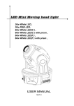
4 CHANNEL DIGITAL PROPORTIONAL RADIO CONTROL SYSTEM ETB41-2.4GHz RIC SYSTEM OPERATING MANUAL ~~GH2 nsss ~. TABLE OF CONTENTS Package List 3 Precautions for Keeping 3 Meaning of Special Markings 4 Precautions During Flight Warning 4 Transmitter 5 Receiver 9 Manual for Brushed ESC 10 Transmitter Operation and Movement of each Servo 11 Adjustments The Process Of Frequency Bind For 2.4GHz RIC System Flight simulation system instruction Glossary 2 13 5 ........................21 Thank you for purchasing the E-Fly ETB41-2.4GHz Digital Proportional Radio Control System. Before you operate this unit, please read and keep this manual carefully. Please comply the proper procedures strictly, user must be responsible for the damages of radio system and model or other loss caused by incorrect operation. Transmitter Receiver Servo Simulator cable Radio neck strap ESC-30(30A) Great Features: E-FLY ETB41-2.4GHz E-FLY ER61-2.4GHz AS-1 00 (9 gram) ( Users can buy as spare parts) 1 pes 1 pes 3pcs 1 pes (optional) 1 pes • Fully proportional • Servo reverse function • High quality joystick • Trainer port available • Remote control • • Low voltage alarm If it is your first using, please make sure the receiver can be controlled by the transmitter. If not, please rebind. Details can be found in Bind Process Description.the transmitter and the receiver must be bind again. More details, ease refer to the process of frequency bind for 2.4 GHz RIC System. • Please do not turn on several RC devices and bind them at the same time, only turn on a set of RC device at one time. • Do not store the radio system in the damp, dusty and vibratory place, temperature over 40°C or under -10°C and direct sunlight for long time. • If there is a long time not for use, please take the battery out from the transmitter and keep it in the dry place. • Forbid to wipe the radio system with the organic liquor such as thinner, acetone and chloroform. • Do not throwaway the using up batteries, please keep them in the metalloid container and transfer them to the environmental conservation institution. • On purpose of environmental conservation and low using cost, we suggest you use the rechargeable Ni-MH battery. .art-te c Pay special attention to the safety at the parts of this manual that are indicated by the following marks. MEANING MARK Procedures which may lead to a dangerous condition DANGER WARNING and cause death or serious injury to theuser if not carried out properly. & Procedures which may lead to dangerous condition or • cause death or serious injury to the user if not carried out properly, or procedures where the probability of superficial injury or physical damage is high. CAUTION Procedures where the possibility of serious injury to the user is small, but there is a danger of injury, or physical damage, if not carried out properly. Symbol: <S)Prohibited & • Mandatory WARNING! Do not fly in rainy or windy days, or at night. Water will penetrate into the transmitter and cause faulty operation, or loss of control, and cause a crash. Always test the digital proportional RIC set before use. Any abnormality in the digital proportional RIC set, or model, may cause a crash. Before starting the engine, check that the direction of operation of each servo matches the operation of its control stick. If a servo does not move in the proper direction, or operation is abnormal, do not fly the plane. The transmitter can not work properly if the frequency bind button is pressed down neglectfully. In this case, The transmitter and the receiver must be bind again. More details, ease refer to the process of frequency bind for 2.4 GHz RIC system. Please do not turn on several RC devices and bind them at the same time, bind only one set of RC device at one time. The RC device should not be stay in bind state for a long time. Do not fly the plane near the house, road, electrical wire and airport. • We offer Mode I and Mode II two types of transmitter for selection. Customers should choose one according to their individual needs. • You will need 8 AAA batteries for operating the transmitter. .&. • Low battery voltage alarm function. The transmitter will emit a high-pitched tone if the battery voltage gets too low. I (Mode 1) Antenna Hook Throttle Max Aileron right Elevator down R~~~e~;lF,R~~~~r Elevator up Throttle Min Power indicator Trim Charger Frequency Switch Servo reverse (Mode 2) Anten ·",rlr\l;r"., bar Hook Throttle Max Rudder Rudder left right Elevator down Aileron Aileron left ....... right Throttle Min Elevator up Power indicator Trim Power switch Charger port ***** ....... ,'·**0"0··* Frequency Switch Servo reverse (Mode 1) Antenna Ca bar Hook R~~~e~li;R~~~~r Throttle Max Aileron .:i: Aileron left ~ right Elevator up Throttle Min Elevator down Power indicator Trim Power switch Charger Frequency Switch Model MIX: delta-wing or V type tail-wing mode NOR: normal m..:o .:d,:.e,..~~ ~ . (Mode 2) Antenna bar Hook Throttle Max Rudder Rudder left right Elevator down Aileron Aileron left right Throttle Min Elevator up Trim Power Charger c:"."it",'h Frequency Switch Model MIX: delta-wing or V type tail-wing mode NOR: normal mode . com • Servo reversing switches • If the direction of servo operation is not the same as the model, adjust the reversing switches to reverse the direction. The lower position is the normal setting and the upper position is the reverse setting. Channel display AIL.: Aileron ELE.: Elevator THR.: Throttle RUD.: Rudder (CH 1) (Ch2) (CH3) (CH4) • Working modes' option MIX: delta-wing orV type tail-wing mode NOR: normal mode • Operating direction display REV.: Reverse setting NOR.: Normal setting Stick lever spring tension adjustment The stick spring tension can be adjusted. The operating feel of the aileron, elevator, and rudder sticks can be individually adjusted. • Remove the four transmitter rear case screws and remove the rea case. • Adjust the spring strength by turning the screw of the channel you want to adjust. • Close the rear case and tighten The four screws.Stick length adjustment. • Turn the head of stick. • TRAINER JACK Connects the trainer cord when using the trainer function (The trainer cord is sold separately), see part 8 for the details of the trainer function. • BATTERY COVER Use when replacing the battery. Slide the cover downward while pressing the part marked [] PUSH D With E-FLY ER61-2.4GHz receiver, the max range is 1000 feet (350m) in the air, suitable for small park flyer type model plane. Output channels OPERATION FOR AIRPLANES Signal (White line) + (Red line) ' OPERATION FOR COAXAL DUAL ROTOR B. Power/ Frequency bind 6. Flapron 5. Landing gear 4. Rudder 3. Throttle 2. Elevator 1. Aileron (Black line) B. Power/ Frequency bind , Signal (White line) L + (Red line) 4. Rudder 3. Throttle 2. Elevator 1. Aileron (Black line) SPECIFICATIONS AND PARAME"rERS • • • • • Operating voltage: 4.8V-5.2V • Channel: 6CH • Range(Height): ;?350m Current drain: ::s;40mA ;?50m (withcoaxal dual rotor) Weight: 12g Dimension: 44mm*23mm*15mm Adjacent channel rejection: ;? -85dBm Specifications for ESC-30A Working currency:30Al50A(max currency) input voltage: DC,5V-14.4V. starting mode: adaptable point ( 1.0ms-1.5ms ) control mode: 200 class proportional output voltage(BEC) : 5V/1 A(direct for servo) To battery + To receiver To battery - '" ~ ~~!1!!S!!.'~," Electronic Speed ~ -< "" Controller e ;r: Q ~ "" To motor e Auto cut-off function When the voltage of battery in model plane is under working voltage, ESC has the function of cutting the power to the motor and only supply to receiver in order to save power. In that case, the model plane should be landed immediately for the sake of safety. • Notice It is better to choose proper motor and battery in oder not to over load. And please pay attention to the conntion between ESC and the motor. In working condition, tile ESC will become hot,so please pay attention to that. Before making any adjustments, learn the operation of the transmitter and the movement of each servo. (In the following descriptions, the transmitter is assumed to be in the standby state.) AILERON OPERATION When the aileron stick is moved to the right, the right aileron is raised and the left aileron is lowered, relative to the direction of flight, and the plane turns to the right. When the aileron stick is moved to the left, the ailerons move in the opposite direction. ELEVATOR OPERATION When the elevator stick is pulled back, the tail elevator is raised and the tail of the plane is forced down, the airflow applied to the wings is changed, the lifting force is increased, and the plane climbs (UP operation). When the elevator stick is pushed forward, the elevator is lowered, the tail of the plane is forced up, the air flow applied to the wings is changed, the lifting force is decreased, and the plane dives (DOWN operation). THROTTLE OPERATION When the throttle stick is pulled back, the engine throttle lever arm moves to the SLOW (low speed) position. When the throttle stick is pushed forward, the throttle lever arm moves to the HIGH (hiqh speed) position. RUDDER OPERATION When the rudder stick is moved to the right, the rudder moves to the right and the nose points to the right, relative to the direction of flight. When the rudder stick is moved to the left, the rudder moves to the left and the nose points to the left and the direction of travel of the plane changes. The operating direction, neutral position, and steering angle of each servo are adjusted. ADJUSTMENT PROCEDURE Before making any adjustments, set all the SERVO REVERSER switches on the front of the transmitter to the lower (NOR) position. (Switch the switches with a small screwdriver, etc.) Turn on the transmitter and receiver power switches and make the following adjustments: 1. Check the direction of operation of each servo If a servo operates in the wrong direction, switch its SERVO REVERSER switch. (The direction of operation can be changed without changing the linkage.) * Note that the direction of the aileron servo is easily mistaken. 2. Check the aileron, elevator, and rudder neutral adjustment and left-right (up down) throw. Check that when trimmed to the center, the servo horn is perpendicular to the servo and check the neutral position of the fuselage control surfaces (aileron, elevator, rudder, etc.). If the neutral position has changed, reset it by adjusting the length of the rod with tile linkage rod adjuster. When the throw is unsuitable (different from steering angle specified by the kit instruction manual), adjust it by changing the servo horn and each control surface horn rod. 3. Check the engine throttle (speed adjustment) linkage. Change the servo horn installation position and hole position so that the throttle is opened fully when the throttle stick is set to HIGH (forward) and is closed fully when the throttle stick and throttle trim are set for maximum slow (backward position and lower position, respectively). 4. After all the linkages have been connected, recheck the operating direction, throw, etc.*Before flight, adjust the aircraft in accordance with the kit and engine instruction manuals. 5. Fly the plane and trim each servo. COAXAL DUAL ROTOR 1 J 1. Press the button for frequency bind, then turn on the transmitter's power. 2. Connect the ESC to receiver for electricity supply, wihch results to the indicator light glitter. And then plug the short-circuit plug into the Receiver in the position of BATT. 3. If the frequency bind is successful, the indicator light will extinguish. 4. Press frequency bind button again to get it rebound. The transmitter get into working mode. 5. The indicator light turns bright again seconds after pulling out the short-circuit plug, which means that the radio system can work normally now. AIRPLANES * If oil aircraft, please connect the power of receiver to other channel at first, and then plug it to BATT after frequency bind. 1. Press the button for frequency bind, then turn on the transmitter's power. 2. Connect the ESC to receiver for electricity supply, wihch results to the indicator light glitter. And then plug the short-circuit plug into the Receiver in the position of BATT. 3. If the frequency bind is successful, the indicator light will extinguish. 4. Press frequency bind button again to get it rebound. The transmitter get into working mode. 5. The indicator light turns bright again seconds after pulling out the short-circuit plug, which means that the radio system can work normally now. System requirements: above windows 2000 1.Flight simulation system includes: one CD, one audio cable, and one operation manual. 2.Please insert the appropriate end of the supplied cable to your transmitter, and the other end to the IVII C port. Pink Pink 3.Click "Start / Programs / Accessories / Entertainment / Sound Recorder" to open the Sound Recorder. Then click "Edit / Audio Properties" to open Audio Properties. 4.Click "Volume ... ",and choose the MIC, and adjust the volume to about 2/3 of full volume. Then click and to exit. 5.Click on the record button,( following the fig.) switch on the transmitter, and record the signal of the transmitter to make sure all connections are correct. If everything is wording properly you should see the wave pattern of the transmitted signal. If not, check the connections and audio settings. 6, Insert the CD-Rom and open it, copy it. Click 1 '"' Fr·~·:; 1 - from the CD to your C:/, and open to run "FMS", click "Controls" and select "Analog control. ..". ReMme ths fo!del t~0",e Ihls f~ CQP'~ tl"t,s roldtr Put.1lr)lI~ f~~r to tlv: Web ShMe !hls Icl~ (~ !Ql~t'$ hle~ Delete fcdC" "'---------------------------------------------------------------- --- - 7. Choose the Joystick interface and click ••. ~~~~~~~...-.I ..• 8.Click 9.Move all joysticks to calibrate the radio. Move aileron joystick to calibrate like the channel 3,move elevator joystick to calibrate like the channel 2, move throttle joystick to calibrate like the channel 4, mov rudder joystick to calibrate like the channel 1.Setup the channels following the figure of the right. (1,2,3,4,1 ,2,3,4).Then click "Next". Click "Finish" completing the calibration. Note :The calibration is very important, it will affect the performances of your model. About the "channel", there is a little different setup on different window system. 10. Now, everything is ready, you can fly the model at any moment you like. 11. Control keys: I: Restart P:Pause Number 2, Number 3, Number 4, Number 5, Number 6, Number 8, Number 9: Change the view. ~ NOTE: THERE ISALITTLE DIFFERENT INSTALLING STEP ON DIFFERENT WINDOW SYSTEM The following defines the symbols and terms used in this instruction manual. AILERON (AIL.) Control surface at the left and right sides of the main wing of an aircraft. It usually controls turning of the aircraft. ELEVATOR(ELE. ) Control surface that moves up and down of the horizontal stabilizer of an aircraft. It usually controls up and down. THROTTLE (THR.) Part that controls the air mixture at the engine intake. When opened (throttle high side), a large air mixture is sucked in and the engine speed increases. W hen closed (throttle low side), the engine speed decreases. ----== RUDDER (RUD.) Tail control surface that controls the direction of the aircraft. Manufacturer reserves the right to make improvements without notice. Forbid to transfer and copy contents in this manual without consent. There will be no notice given of any changes or improvements made. It is forbidden to copy any of the content of this manual without permission. 2008.10 - - - - - - - .