1
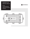
Installation and Operation Manual ID O V EN Y T K N O A R R B R L A EA W S IF GX2-PSAC10D-R Power Supply P 2- 0 pp -0 r Su 01 we -0 Po C 41D-R 00 88C10 00 0 52 SA 30 X G 0 66 P A 06 E ly E9 C 00 X0 669 USE ONLY WITH 250V FUSES M IN O 50/ PU DE L 60 T: 11 : Hz 5/2 G X 4.5 30V 2 -P /2.3 ~ A OU SAC TP 10 UT: D 1 -R 5.1 2V V P 1 RO 17.9 6.1A DUC AM MA TO AX X. 3 F PH . M .7V ILIP AX . PO 1 PINE WE 9.2A S R:3 M 00W AX . D BE ISCOCAU FO N U RE NE TIO CHNIT FREMCT PO N AS RO OV W SIS M IN ER G 86 24 9 -G X 2 R E1 AIH CAUTION RISK OF ELECTRIC SHOCK CAUTION: TO REDUCE THE RISK OF ELECTRIC SHOCK, DO NOT REMOVE COVER (OR BACK). NO USER-SERVICEABLE PARTS INSIDE. REFER SERVICING TO QUALIFIED SERVICE PERSONNEL. Caution These servicing instructions are for use by qualified personnel only. To reduce the risk of electrical shock, do not perform any servicing other than that contained in the Installation and Troubleshooting Instructions unless you are qualified to do so. Refer all servicing to qualified service personnel. Special Symbols That Might Appear on the Equipment This symbol indicates that dangerous voltage levels are present within the equipment. These voltages are not insulated and may be of sufficient strength to cause serious bodily injury when touched. The symbol may also appear on schematics. The exclamation point, within an equilateral triangle, is intended to alert the user to the presence of important installation, servicing, and operating instructions in the documents accompanying the equipment. For continued protection against fire, replace all fuses only with fuses having the same electrical ratings marked at the location of the fuse. This symbol indicates a hot surface. Use caution before touching a surface marked with this symbol. This equipment operates over the marked Voltage and Frequency range without requiring manual setting of any selector switches. Different types of line cord sets may be used for connections to the mains supply circuit and should comply with the electrical code requirements of the country of use. This equipment requires a grounding conductor in the line cord. The line cord provided with the equipment is acceptable for use with NEMA Style 5-15R ac receptacles supplying nominal 120 Volts. WARNING: TO PREVENT FIRE OR SHOCK HAZARD, DO NOT EXPOSE THIS APPLIANCE TO RAIN OR MOISTURE. THE APPARATUS SHALL NOT BE EXPOSED TO DRIPPING OR SPLASHING AND THAT NO OBJECTS FILLED WITH LIQUIDS SHALL BE PLACED ON THE APPARATUS. CAUTION: TO ENSURE REGULATORY AND SAFETY COMPLIANCE, USE ONLY THE RECOMMENDED POWER CABLES. CAUTION: SURFACE MAY BE HOT. DISCONNECT POWER AND ALLOW SURFACE TO COOL BEFORE TOUCHING. It is recommended that the customer install an AC surge arrestor in the AC outlet to which this device is connected. This is to avoid damaging the equipment by local lightning strikes and other electrical surges. FCC Compliance This equipment has been tested and found to comply with the limits for a Class A digital device, pursuant to Part 15 of the FCC Rules. These limits are designed to provide reasonable protection against harmful interference when the equipment is operated in a commercial environment. This equipment generates, uses, and can radiate radio frequency energy and, if not installed and used in accordance with the Installation Manual, may cause harmful interference to radio communications. Operation of this equipment in a residential area is likely to cause harmful interference in which case the user will be required to correct the interference at his/her own expense. Changes or modification not expressly approved by the party responsible for compliance could void the user’s authority to operate the equipment. Canadian Compliance This Class A digital apparatus meets all requirements of the Canadian Interference-Causing Equipment Regulations. Cet appareil numérique de la classe A respects toutes les exigences du Règlement sur le matériel brouilleur du Canada. International Declaration of Conformity We Motorola, Inc. 101 Tournament Drive Horsham, PA 19044, U.S.A. declare under our sole responsibility that the OmniStar® Model GX2-PSAC10D-R to which this declaration relates is in conformity with one or more of the following standards: EMC Standards EN55022 EN55024 EN55013 EN50083-2 CISPR-22 CISPR-24 CISPR-13 EN60825 EN50083-1 EN60950 IEC 60950 + A1: 1992 + A2: 1993 + A3: 1995 + A4: 1996 IEC60065 Safety Standards EN60065 following the provisions of the Directive(s) of the Council of the European Union: EMC Directive 89/336/EEC Low Voltage Directive 73/23/EEC WARNING There is an energy hazard on this built-in power supply. During operation, the operator must not touch the +12V output. This unit contains a secondary output exceeding 240VA. When installing into the end system, care must be taken not to touch the +12V output. Copyright © 2007 by Motorola, Inc. All rights reserved. No part of this publication may be reproduced in any form or by any means or used to make any derivative work (such as translation, transformation or adaptation) without written permission from Motorola, Inc. Motorola reserves the right to revise this publication and to make changes in content from time to time without obligation on the part of Motorola to provide notification of such revision or change. Motorola provides this guide without warranty of any kind, either implied or expressed, including, but not limited to, the implied warranties of merchantability and fitness for a particular purpose. Motorola may make improvements or changes in the product(s) described in this manual at any time. MOTOROLA, the Stylized M Logo, and OmniStar are registered in the US Patent & Trademark Office. All other product or service names are the property of their respective owners. © Motorola, Inc. 2007 Contents Section 1 Introduction Using This Manual ........................................................................................................................................................................... 1-2 Related Documentation................................................................................................................................................................... 1-2 Document Conventions................................................................................................................................................................... 1-2 If You Need Help............................................................................................................................................................................... 1-3 Calling for Repairs ........................................................................................................................................................................... 1-4 Section 2 Overview Redundancy...................................................................................................................................................................................... 2-3 Section 3 Installation and Operation Unpacking......................................................................................................................................................................................... 3-1 Installation ........................................................................................................................................................................................ 3-1 Powering ........................................................................................................................................................................................... 3-2 Operation .......................................................................................................................................................................................... 3-2 Fault Reporting................................................................................................................................................................................. 3-3 Appendix A Specifications Input Power.......................................................................................................................................................................................A-1 Output Power....................................................................................................................................................................................A-1 Physical Properties..........................................................................................................................................................................A-1 Environmental ..................................................................................................................................................................................A-1 Appendix B Menus Module Status Menu ........................................................................................................................................................................B-1 Module Info Menu.............................................................................................................................................................................B-2 Alarms ...............................................................................................................................................................................................B-2 Abbreviations and Acronyms GX2-PSAC10D-R Installation and Operation Manual ii Contents Figures Figure 1-1 GX2-PSAC10D-R............................................................................................................................................................1-1 Figure 2-1 GX2-HSG* fully populated .............................................................................................................................................2-1 Figure 2-2 GX2-PSAC10D-R front view..........................................................................................................................................2-2 Figure 2-3 GX2-PSAC10D-R top view ............................................................................................................................................2-2 Figure 2-4 GX2-PSAC10D-R rear view ...........................................................................................................................................2-3 Figure 3-1 GX2-PSAC10D-R............................................................................................................................................................3-1 Figure 3-2 AC input connector .......................................................................................................................................................3-2 Figure 3-3 GX2-PSAC10D-R block diagram ..................................................................................................................................3-2 Tables Table 3-1 LED fault indication ........................................................................................................................................................3-3 Table B-1 GX2-PSAC10D-R menus ............................................................................................................................................... B-1 GX2-PSAC10D-R Installation and Operation Manual Section 1 Introduction The OmniStar® GX2 is a fiber optic broadband transmission platform for headend and hub locations that supports advanced hybrid-fiber coax telecommunications systems. The GX2 series is a complete line of headend fiber optic products designed to transport video and data signals in CATV systems and related applications. The OmniStar GX2 system is flexible in its application and includes a series of modules and options that you can select to accommodate system requirements. The GX2 system offers a solution for the next generation of broadband network applications where its requirements for smaller node sizes, deployment of point-to-point lasers, and return-path applications optimize operating space. Its high module density enables network operators to install more equipment in less space. The wide operational bandwidth of the platform enables you to offer more revenue-generating services. This manual describes the GX2-PSAC10D-R power supply that provides power for the equipment shelf (GX2-HSG*) and all application modules. The GX2-PSAC10D-R features include: Regulated +5.1, +12, and +3.7 VDC to the equipment shelf backplane Integrated fans for localized cooling Dual power supply option (AC or DC) for load sharing and/or redundancy Microprocessor control and monitoring of critical functions Tri-colored LED for module status indication Wide operating temperature range from –20°C to +60°C Downloadable firmware True Plug-n-Play operation Restriction of Hazardous Substances (RoHS) compliant Figure 1-1 illustrates a rear view of the GX2-PSAC10D-R: F igu re 1-1 GX2-PSAC10D-R USE ONLY WITH 250V FUSES GX2-PSAC10D-R Installation and Operation Manual 1-2 Introduction Using This Manual The following sections provide information and instructions to install the GX2-PSAC10D-R: Section 1 Introduction provides a product description, related documentation, the technical helpline, and repair/return information. Section 2 Overview provides an overview of the GX2 system and a functional description of the GX2-PSAC10D-R. Section 3 Installation and Operation provides instructions on how to install the GX2-PSAC10D-R and verify that it is operating properly. Appendix A Specifications provides general specifications for the GX2-PSAC10D-R. Appendix B Menus provides the GX2-PSAC10D-R menu structure and information on how to use the optional SDU with display. Abbreviations and Acronyms The Abbreviations and Acronyms list contains the full spelling of the short forms used in this manual. Related Documentation The following documents provide information that is required for products that can be used with the GX2-PSAC10D-R: GX2-CM100B Control Module Installation and Operation Manual GX2-PSDC10D-R DC Power Supply Installation and Operation Manual GX2-HSG* Equipment Shelf Installation Manual There are additional documents that provide information that may be of interest to you. These documents are specific to each GX2 application module and are shipped with the product. Document Conventions Before you begin using the GX2-PSAC10D-R, familiarize yourself with the stylistic conventions used in this manual: SMALL CAPS Denotes silk screening on the equipment, typically representing front- and rear-panel controls, input/output (I/O) connections, and light emitting diodes (LEDs) * (asterisk) Indicates that several versions of the same model number exist and the information applies to all models; when the information applies to a specific model, the complete model number is given Italic type Denotes a displayed variable, a variable that you must type, or is used for emphasis GX2-PSAC10D-R Installation and Operation Manual Introduction 1-3 If You Need Help If you need assistance while working with the GX2-PSAC10D-R, contact the Motorola Technical Response Center (TRC): Toll-free: 1-888-944-HELP (1-888-944-4357) Outside the U.S.: 1-215-323-0044 Direct: 1-847-725-4011 Motorola Online: http://businessonline.motorola.com The TRC is on call 24 hours a day, 7 days a week. In addition, Motorola Online offers a searchable solutions database, technical documentation, and low-priority issue creation and tracking. For specific toll-free numbers when calling from outside the United States, please refer to your product manual or our Web page. Technical Response Center Telephone Menu Options Connected Home Solutions http://businessonline.motorola.com 888-944-HELP / 215-323-0044 Broadcaster, Satellite IRD or Encoder Products PRESS 2 Video Products PRESS 1 PRESS 1 Controllers PRESS 1 Digital PRESS 2 Headend PRESS 2 Uplink Encoder PRESS 1 Commercial IRD PRESS 3 Set-tops PRESS 2 Analog Consumer Products PRESS 4 Data Networks/ Transmission Products PRESS 3 PRESS 3 PRESS 2 PRESS 1 Cable Router Cable Modems Transmission Products VOIP Products Severity Level 1 - Critical Failure 2 - Serious Failure 3 - Lesser Failure 4 - Technical Assistance PRESS 4 Network Management PRESS 5 Multiservice Transport Products (MBT/MWT/MEA) PRESS 1 Consumer Satellite C Band PRESS 2 Broadband Retail Support PRESS 2 PRESS 1 Network Network Licensing Management Products Issued: 04/2005 GX2-PSAC10D-R Installation and Operation Manual 1-4 Introduction Calling for Repairs If repair is necessary, call Motorola’s Repair Facility at 1-800-227-0450 for a Return for Service Authorization (RSA) number before sending the unit. The RSA number must be prominently displayed on all equipment cartons. The Repair Facility is open from 8:00 AM to 5:00 PM Central Time, Monday through Friday.. When calling from outside the United States, use the appropriate international access code, and then call 956-541-0600 to contact the Repair Facility. When shipping equipment for repair, follow these steps: 1 Pack the unit securely. 2 Enclose a note describing the exact problem. 3 Enclose a copy of the invoice that verifies the warranty status. 4 Ship the unit PREPAID to the address indicated on the RSA form provided by Motorola. GX2-PSAC10D-R Installation and Operation Manual Section 2 Overview The OmniStar GX2 platform provides increased rack density, reliability, ease of operation, and computer-aided troubleshooting through the extensive use of status monitoring. Low time-to-repair is facilitated because application modules are accessible and replaceable from the front of the OmniStar GX2 equipment shelf. Fiber connections are also located in the front while RF and power connections are located on the rear of the equipment shelf. Basic components of the OmniStar GX2 system include: Equipment shelf model GX2-HSG* Control module GX2-CM100B Power supply module GX2-PSAC10D-R or GX2-PSDC10D-R A series of application modules to fit any system requirement Figure 2-1 illustrates a front view of a fully populated GX2-HSG*: Figure 2-1 GX2-HSG* fully populated The GX2-PSAC10D-R provides +5.1, +12, and +3.7 VDC power to the GX2-HSG* and all application modules. The auto-sensing input-voltage feature recognizes 115 VAC or 230 VAC applications. Surge protection for the input plus overcurrent protection for the output provide the necessary safeguards for the power supply and the application modules served by it. A large heatsink and integrated fans dissipate the internally generated heat and keep the module temperature within acceptable limits. GX2-PSAC10D-R Installation and Operation Manual 2-2 Overview Figure 2-2 illustrates a front view of the GX2-PSAC10D-R: Figure 2-2 G X 2 - P S AC 1 0 D - R f r o n t vi ew Figure 2-3 illustrates a top view of the GX2-PSAC10D-R: Figure 2-3 G X 2 - P S AC 1 0 D - R t o p vi ew CAUTION Surface may be hot. Disconnect power and allow surface to cool before touching. GX2-PSAC10D-R Installation and Operation Manual Overview 2-3 Figure 2-4 illustrates a rear view of the GX2-PSAC10D-R: Figure 2-4 G X 2 - P S AC 1 0 D - R r e a r vi ew IEC LED connector Thumbscrews Redundancy The unused compartment on the bottom of the GX2-HSG* can be used for redundant powering with the purchase of a second power supply. For redundancy, it is possible to use two GX2-PSAC10D-R's (as shown in Figure 3-1), two GX2-PSDC10Cs, or any combination of GX2-PS*10* power supplies. To provide load sharing in addition to redundancy, you must use two power supplies with model numbers ending in the same letter suffix. The exception to this rule is that models ending in “D-R” will load share with models ending in “C”. If one power supply fails, the other assumes the entire load. GX2-PSAC10D-R Installation and Operation Manual Section 3 Installation and Operation This section provides instructions to install the GX2-PSAC10D-R power supply in the GX2-HSG* and verify its operation. Unpacking Unpack the GX2-PSAC10D-R and inspect it for damage. If damage is visible, set it aside in the original packing material and contact the Motorola Customer Service Department for further instructions. Record the model number, serial number, and related information for future reference. Installation To operate, the GX2-HSG* must be equipped with a GX2-PSAC10D-R or GX2-PSDC10D-R power supply. To install the GX2-PSAC10D-R power supply: 1 Rotate the power supply so that the cooling fans face you and the external power connection is on the left. 2 Position the power supply into the left- or right-side power supply compartment on the rear of the GX2-HSG* as illustrated in Figure 3-1: Figure 3-1 G X 2 - P S AC 1 0 D - R 3 Insert the power supply completely into the chassis ensuring that connection is made with the backplane connectors. 4 Secure the power supply by tightening the two captive thumbscrews into the GX2-HSG*. 5 Plug the IEC connector end of the ac power cord into the rear of the GX2-PSAC10D-R. GX2-PSAC10D-R Installation and Operation Manual 3-2 Installation and Operation Powering After all connections, including fiber, have been established, apply power to the GX2-HSG*. Power connections are in the rear of the equipment shelf as illustrated in Figure 3-1. Using the supplied cable, provide power from a source voltage of 105 VAC to 264 VAC to the AC input connector on the rear of the GX2-PSAC10D-R as illustrated in Figure 3-2: Figure 3-2 AC i n p u t c o n n e c t o r Before removing a power supply from the GX2-HSG*, disconnect the power input cable from the rear of the GX2-PS*10*. If a GX2-PS*10* is removed before power is disrupted, you must wait approximately five minutes before restoring power or the unit may not start properly. In normal operation, it is not necessary to remove power from the equipment shelf when installing a new module or replacing one. The shelf and all modules are designed to enable module replacement with power applied. Operation The AC input voltage, which must be between 105 Vrms and 264 Vrms, is filtered and then applied to a power-factor control circuit that converts the AC voltage to DC. The high voltage DC is applied to three DC/DC converters. The converters, one for each of the three output voltages, supply precisely regulated output voltages of +5.1, +12, and +3.7 VDC respectively. Short circuit protection is provided by each of the DC/DC converters to limit the output current until the fault is cleared. Figure 3-3 illustrates a block diagram of the GX2-PSAC10D-R: Figure 3-3 G X 2 - P S AC 1 0 D - R b l o c k d i a g r a m GX2-PSAC10D-R Installation and Operation Manual Installation and Operation 3-3 Fault Reporting Each output voltage and the internal voltage of the supplies is monitored. The temperature of the incoming air, the heat sink, and fan operation are monitored as well. In the event of a fan failure, a major alarm is sent to the GX2-CM100B control module and the local LED glows red. The monitored signals are all compared to their appropriate internal specification. When a deviation occurs, either a minor or major alarm is sent to the control module, and the appropriate LED color on the GX2-PSAC10D-R illuminates. Table 3-1 lists the possible LED colors and the probable fault indication: Table 3-1 LED fault indication LED color Fault Indication Green Power is applied and all measured parameters are within tolerance. Yellow A minor alarm is detected, however, the GX2-PSAC10D-R is not rendered inoperative. Red A major alarm is detected and immediate intervention is required. Not lit If the LED is not lit, verify that system power is available. The GX2-PSAC10D-R also includes non-volatile memory to store module identity information that includes model number, serial number, and manufacturing date code. To access this information, the GX2-CM100B Control Module must be installed in the GX2-HSG*. Data from the GX2-PSAC10D-R is reported to the GX2-CM100B and is accessible through the GX2-SDU or the Ethernet port on the front panel. Using the GX2-SDU, or a network management system, you can identify the cause of a fault in the GX2-PSAC10D-R. Refer to Appendix B, Menus, for information regarding the SDU menu structure. The GX2-CM100B front panel also contains two tri-colored LEDs identified as PS1 and PS2. These LEDs give the same indication as identified in Table 3-1. If the PS1 or PS2 LED is not lit, then a power supply is not installed or the installed power supply is not functional. If one power supply fails in a redundant application, you can still access the failed power supply through the SDU or EMS. This is possible as the microprocessor on each power supply is powered from the backplane voltage rather than internally from the power supply. GX2-PSAC10D-R Installation and Operation Manual Ap pen dix A Specifications Specifications for the GX2-PSAC10D-R are valid over the given operating temperature range. Refer to the current Motorola BCS product catalog for additional information not provided in this section. Input Power AC input voltage 105 Vrms to 264 Vrms AC current At 115 V At 230 V 4.0 amps rms maximum with full load 2.0 amps rms maximum with full load Power consumption 420 watts maximum with full load Efficiency 68% at maximum load Fusing Two 10 amp slow blow at power input connector Output Power Output voltage +5.1 VDC range +12 VDC range +3.7 VDC range 5.05 to 5.15 VDC nominal with maximum load at +25°C 11.88 to 12.12 VDC nominal with maximum load at +25°C 3.66 to 3.75 VDC nominal with maximum load at +25°C Output current +5.1 VDC range +12 VDC range +3.7 VDC range 17.9 amps maximum with maximum load at +25°C 16.1 amps maximum with maximum load at +25°C 19.2 amps maximum with maximum load at +25°C Maximum total output power 300 Watts Physical Properties Dimensions 2.2” H x 7.7” W x 11.7” D (5.6 cm x 19.6 cm x 29.7 cm) Weight 8.0 lb (3.6 kg) Mounting GX2-HSG* Environmental Operating temperature range -20°C to +60°C (-4° to +140°F) Storage temperature range -40°C to +85°C (-40° to +186°F) GX2-PSAC10D-R Installation and Operation Manual Ap pen dix B Menus This appendix provides information about: Using the optional SDU with display to access GX2-PSAC10D-R menus The menu structure Alarms Table B-1 identifies the procedure for navigating through the GX2-PSAC10D-R menus using the optional SDU with display: Table B-1 G X 2 - P S AC 1 0 D - R m e n u s To Use Scroll to the top-level power supply menu Press the up or down arrows to scroll to the PS1 or PS2 menu. If a power supply is not installed, EMPTY is displayed after the PS1 or PS2. Enter a level two menu from the top-level PS1 or PS2 menu Press the right arrow. Then press the up and down arrows to scroll to the MODULE STATUS MENU or the MODULE INFO MENU. Change a parameter value Press the right arrow to enter edit mode. Use the up and down arrows to change the value. Press ENTER to save the new value or press the left arrow to exit edit mode without changing the value. If you press no key for 10 to 15 seconds, you exit edit mode with the value unchanged. Go up from level two to level one Press the left arrow. The following subsections provide the menu structure: Module Status Menu The italicized x’s in this table indicate a displayed variable: Parameter Value AMBIENT TEMPERATURE: xx.x °C HEATSINK TEMPERATURE: xx.x °C BACKPLANE +12 V: +5.1 V: +3.7 V: xx.x V x.x V x.x V GX2-PSAC10D-R Installation and Operation Manual B-2 Menus Module Info Menu ALIAS> User selected (default GX2-POWER SUPPLY) MODEL: GX2-PSAC10D-R S/N: 0123456789ABCDEF DATE CODE: mmddyyyy FW REV: XX HW REV: XX Alarms The second line on the SDU can display any of the following messages when an alarm condition exists: FAN CURRENT ALARM +12V BACKPLANE ALARM +5.1V BACKPLANE ALARM +3.7V BACKPLANE ALARM AMBIENT TEMPERATURE ALARM HEATSINK TEMPERATURE ALARM BANK 0 BOOT ALARM BANK 1 BOOT ALARM FLASH ALARM FACTORY CRC ALARM ALARM CRC ALARM MODEL NAME ALARM POWER SUPPLY FAIL GX2-PSAC10D-R Installation and Operation Manual Abbreviations and Acronyms The abbreviations and acronyms list contains the full spelling of the short forms used in this manual: CATV Community Antenna Television dB decibels dBm decibels referenced to one milliwatt dBc decibels relative to carrier level dBmV decibels referenced to one millivolt ESD electrostatic discharge LED light-emitting diode MHz Megahertz mW milliwatts RF radio frequency RSA Return for Service Authorization TRC Technical Response Center TTR time-to-repair GX2-PSAC10D-R Installation and Operation Manual Visit our website at: www.motorola.com 538445-001-a 5/07