1
These instructions must be read and understood completely before attempting
installation.
Safety Labeling and Signal Words
DANGER,
WARNING,
CAUTION,
and NOTE
Signal
The
signal
words
DANGER,
WARNING,
CAUTION, and NOTE are used to identify levels of
hazard seriousness.
The signal word DANGER is
only used on product labels to signify an immediate
hazard. The signal words WARNING,
CAUTION,
and NOTE will be used on product labels and
throughout this manual and other manual that may
apply to the product.
Words
in Manuals
The signal word WARNING
this manual in the following
is used throughout
manner:
The signal word CAUTION
this manual in the following
is used throughout
manner:
DANGER - Immediate hazards which will result in
severe personal injury or death.
WARNING
- Hazards or unsafe practices which
could result in severe personal injury or death.
Signal
Z_
CONSiDERATiONS
......................................
..............................................
AND STANDARDS
ELECTROSTATIC
DIMENSIONS
.......................................
DISCHARGE
(ESD) PRECAUTIONS
PROCEDURE
..........
RELATIVE
TO COOLING
AiR FOR COMBUSTION
CONDENSATE
TRAP
iNSTALLATION
MAXIMUM
EQUIVALENT
VENT
4
MAXIMUM
ALLOWABLE
EXPOSED
4
MAXIMUM
LENGTH
AND VENTiLATiON
.......................
...........................
18
HORIZONTAL
iNSTALLATiON
.....................................
20
........................................
23
..................................................
.................................................
25
ELECTRICAL
CONNECTIONS
27
DIRECT
VENT
TERMINATION
PROVINCES
iNSTALLING
20001.
.........................................
/ 2-PIPE
SYSTEM
COMBUSTION
OF ALBERTA
THE
AND
material
Printed
inU.S.A.
.......
31
32
...........................
32
FOR THE
SASKATCHEWAN
......................
..............................
of the text and tables are reprinted from NFPA 54/ANSI
This reprinted
iN CANADA
..................................
VENT TERMINATION
(M) ....
47
47
Use of the AHRI Certified TM Mark indicates a
manufacturer's
participation
in the program,
For verification
of certification
for individual
products,
31
FOR INSTALLATIONS
AiR SYSTEMS
REQUIREMENTS
PIPE-FT
_1_
27
...................................................
VENTILATED
Portions
.....................................
REQUIREMENTS
VENT
IS0 9001
25
GAS PiPiNG
VENTING
INSULATED
17
.....................................
SPECIAL
46
SPACE
17
........................................
iNSTALLATION
AND
.................
iN UNCONDITIONED
9
iNSTALLATiON
VENTING
OF UNiNSULATED
(METERS)
LENGTHS
10
DOWNFLOW
AiR DUCTS
- FEET
VENT
9
...............................................
FILTER ARRANGEMENT
LENTH
7
EQUIPMENT
...........................................
INSTALLATION
3
6
..................................................
LOCATION
J-BOX
symbol
5
................................................
LOCATION
UPFLOW
Safety-alert
OF CONTENTS
iNTRODUCTiON
CODES
Labeling
When you see this symbol on the unit and in
instructions
or manuals,
be alert to the
potential for personal injury.
NOTE - Used to highlight suggestions
which will
result
in enhanced
installation,
reliability,
or
operation.
SAFETY
on Product
Signal words are used in combination with
colors and/or pictures or product labels.
CAUTION
- Hazards or unsafe practices which
may result in minor personal injury or product or
property damage.
TABLE
Words
is not the complete
37
go to www,ahridirectory.org
.
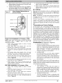
INSTALLER: Affix these instructions on or adjacent to the
furnace,
CONSUMER:
Retain these instructions
for future
reference.
42
Z223.1-2009(_;P, with permission
of National
Fire Protection
and official position of the NFPA or ANSI, on the referenced
subject,
Association,
Quincy, MA 02269 and American
which is represented
only
by the standard
Gas Association,
Washington,
in its entirety,
440 01 4201 01 Sept.2011
DC
Required Notice for Massachusetts
Installations
Important
The Commonwealth
of Massachusetts
5.08: Modifications
to NFPA-54,
requires compliance
Chapter
with regulation 248 CMR as follows:
10
2) Revise 10.8.3 by adding the following additional requirements:
(a)
For all side wall horizontally vented gas fueled equipment installed in every dwelling, building or structure used in whole or in part for residential
purposes, including those owned or operated by the Commonwealth and where the side wall exhaust vent termination is less than seven (7) feet
above finished grade in the area of the venting, including but not limited to decks and porches, the following requirements shall be satisfied:
INSTALLATION OF CARBON MONOXIDE DETECTORS. At the time of installation of the side wall horizontal vented gas fueled equipment, the
installing plumber or gasfitter shall observe that a hard wired carbon monoxide detector with an alarm and battery back-up is installed on the floor
level where the gas equipment is to be installed. In addition, the installing plumber or gasfitter shall observe that a battery operated or hard wired
carbon monoxide detector with an alarm is installed on each additional level of the dwelling, building or structure served by the side wall
horizontal vented gas fueled equipment. It shall be the responsibility of the property owner to secure the services of qualified license professionals
for the installation of hard wired carbon monoxide detectors.
1,
a. In the event that the side wall horizontally vented gas fueled equipment is installed in a crawl space or an attic, the hard wired carbon
monoxide detector with alarm and battery back-up may be installed on the next adjacent floor level.
b. In the event that the requirements of this subdivision can not be met at the time of completion of installation, the owner shall have a period of
thirty (30) days to comply with the above requirement; provided, however, that during said thirty (30) day period, a battery operated carbon
monoxide detector with an alarm shall be installed.
(b)
(c)
(d)
(e)
2.
APPROVED CARBON MONOXIDE DETECTORS. Each carbon monoxide detector as required in accordance with the above provisions shall
comply with NFPA 720 and be ANSI/UL 2034 listed and IAS certified.
3.
SIGNAGE. A metal or plastic identification plate shall be permanently mounted to the exterior of the building at a minimum height of eight (8) feet
above grade directly in line with the exhaust vent terminal for the horizontally vented gas fueled heating appliance or equipment. The sign shall
read, in print size no less than one-half (1/2) inch in size, "GAS VENT DIRECTLY BELOW. KEEP CLEAR OF ALL OBSTRUCTIONS".
4.
INSPECTION. The state of local gas inspector of the side wall horizontally vented gas fueled equipment shall not approve the installation unless,
upon inspection, the inspector observes carbon monoxide detectors and signage installed in accordance with the provisions of 248 CMR
5.08(2)(a) 1 through 4.
EXEMPTIONS:
The following equipment
is exempt from 248 CMR 5.08(2)(a)
listed in Chapter 10 entitled "Equipment
1 through 4:
1.
The equipment
Board; and
Not Required To Be Vented" in the most current edition of NFPA 54 as adopted by the
2.
Product Approved side wall horizontally vented gas fueled equipment installed in a room or structure separate from the dwelling, building or
structure used in whole or in part for residential purposes.
MANUFACTURER REQUIREMENTS - GAS EQUIPMENT VENTING SYSTEM PROVIDED. When the manufacturer of Product Approved side wall
horizontally vented gas equipment provides a venting system design or venting system components with the equipment, the instructions provided by
the manufacturer for installation of the equipment and the venting system shall include:
1.
Detailed instructions for the installation of the venting system design or the venting system components;
2.
A complete parts list for the venting system design or venting system.
and
MANUFACTURER REQUIREMENTS - GAS EQUIPMENT VENTING SYSTEM NOT PROVIDED. When the manufacturer of a Product Approved side
wall horizontally vented gas fueled equipment does not provide the parts for venting the flue gases, but identifies "special venting systems", the
following requirements shall be satisfied by the manufacturer:
1.
The referenced
"special venting system" instructions
shall be included with the appliance or equipment installation instructions;
2.
The "special venting systems" shall be Product Approved
installation instructions.
and
by the Board, and the instructions for that system shall include a parts list and detailed
A copy of all installation instructions for all Product Approved side wall horizontally vented gas fueled equipment, all venting instructions, all parts lists
for venting instructions, and/or all venting design instructions shall remain with the appliance or equipment at the completion of the installation.
For questions
regarding these requirements,
please contact the Commonwealth
Fitters, 239 Causeway
2
Specifications
of Massachusetts
Board of State Examiners of Plumbers and Gas
Street, Boston, MA 02114. 617-727-9952
are subject to change without notice.
440 01 4201
01
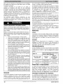
Safety Considerations
CUT HAZARD
FIRE, EXPLOSION,
ELECTRICAL
SHOCK,
CARBON MONOXIDE POISONING HAZARD
AND
Failure to follow this warning could result in dangerous
operation, personal injury, death, or property damage.
Improper installation, adjustment, alteration, service,
maintenance, or use can cause carbon monoxide
poisoning, explosion, fire, electrical shock, or other
conditions which may cause personal injury or property
damage. Consult a qualified service agency, local gas
supplier, or your distributor or branch for information or
assistance. The qualified service agency must use
only factory-authorized and listed kits or accessories
when modifying this product.
FURNACE
RELIABILITY
Failure to follow this
component damage.
HAZARD
caution
may
result
in unit
Application of this furnace should be indoors with
special attention given to vent sizing and material, gas
input rate, air temperature rise, unit leveling, and unit
sizing.
Improper
installation,
adjustment,
alteration,
service,
maintenance, or use can cause explosion, fire, electrical shock,
or other conditions which may cause death, personal injury or
property damage. Consult a qualified installer, service agency,
local gas supplier, or your distributor or branch for information
or assistance. The qualified installer or agency must use only
factory-authorized
kits or accessories when modifying this
product. Refer to the individual instructions packaged with the
kits or accessories when installing.
Installing and servicing heating equipment can be hazardous
due to gas and electrical components. Only trained and
qualified
personnel
should install, repair, or service
heating equipment. Untrained personnel can perform basic
maintenance functions such as cleaning and replacing air
filters. All other operations must be performed by trained
service personnel. When working on heating equipment,
observe precautions in literature, on tags, and on labels
attached
to or shipped with furnace
and other safety
precautions that may apply.
These instructions cover minimum requirements and conform
to existing national standards and safety codes. In some
instances, these instructions exceed certain local codes and
ordinances, especially those that may not have kept up with
changing residential construction practices. We require these
instructions as a minimum for a safe installation.
Failure to follow this caution may result in personal
injury.
Sheet metal parts may have sharp edges or burrs. Use
care and wear appropriate protective clothing, safety
glasses and gloves when handling parts, and servicing
furnaces.
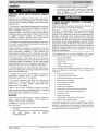
This is the safety-alert symbol /N • When you see this symbol
on the furnace and in instructions or manuals, be alert to the
potential for personal injury.
Understand
the signal words DANGER, WARNING,
and
CAUTION. These words are used with the safety-alert symbol.
DANGER identifies the most serious hazards which will result
in severe personal injury or death. WARNING signifies a
hazard which could result in personal injury or death.
CAUTION is used to identify hazards which may result in minor
personal injury or product and property damage. NOTE is used
to highlight
suggestions
which will result in enhanced
installation, reliability, or operation.
1. Use only with type of gas approved for this furnace.
Refer to the furnace rating plate.
2. Install this furnace only in a location and position as
specified in the "Location" section of these instructions.
3. Provide adequate combustion and ventilation air to the
furnace space as specified in "Air for Combustion and
Ventilation" section.
4.
Combustion products must be discharged outdoors.
Connect this furnace to an approved vent system only,
as specified
in the "Venting" section of these
instructions.
5.
Never test for gas leaks with an open flame. Use a
commercially available soap solution made specifically
for the detection of leaks to check all connections, as
specified in the "Gas Piping" section.
Always install furnace to operate within the furnace's
intended temperature-rise
range with a duct system
which has an external static pressure within the
allowable range, as specified
in the "Start-Up,
Adjustments, and Safety Check" section. See furnace
rating plate.
When a furnace is installed so that supply ducts carry air
circulated by the furnace to areas outside the space
containing the furnace, the return air shall also be
handled by duct(s) sealed to the furnace casing and
terminating outside the space containing the furnace.
See "Air Ducts" section.
6.
7.
8.
9.
10.
Follow all safety codes. Wear safety glasses, protective
clothing, and work gloves. Have a fire extinguisher available.
Read these instructions thoroughly and follow all warnings or
cautions included in literature and attached to the unit.
11.
440 01 4201 01
Specificati .....
bject to change without
A gas-fired furnace for installation in a residential
garage must be installed as specified in the warning box
in the "Location" section. (See Figure 4)
The furnace may be used for construction heat provided
that the furnace installation and operation complies with
the first CAUTION in the LOCATION section on page 7
of these instructions.
These Multipoise Gas-Fired
Furnaces are CSA
design-certified for use with natural and propane gases
(see furnace rating plate) and for installation in alcoves,
attics, basements, closets, utility rooms, crawlspaces,
and garages. The furnace is factory-shipped
for use
with natural gas. A CSA (A.G.A. and C.G.A.) listed
accessory gas conversion kit is required to convert
furnace for use with propane gas.
See Table 1 for required clearances to combustible
construction.
notice.
3
12.
Maintain a 1-in. (25 mm) clearance from combustible
materials to supply air ductwork for a distance of 36-in.
(914 mm) horizontally from the furnace. See NFPA 90B
or local code for further requirements.
Table 1
SUPPLY
Minimum Clearances to
Combustible Materials for All Units
REAR
FRONT
FRONT (Combustion air openings in
furnace and in structure)
1 (25)
Required for service
24 (610)
All Sides of Supply Plenum
Sides
1 (25)
0
Vent
0
Top of Furnace
1 (25)
MIN 60°F/16°C
These furnaces SHALL NOT be installed directly on
carpeting, tile, or any other combustible material other
than wood flooring. In downflow installations, factory
accessory floor base MUST be used when installed on
combustible materials and wood flooring. Special base
is not required when this furnace is installed on
manufacturer's Coil Assembly is used. See Table 1 for
clearance to combustible construction information.
Introduction
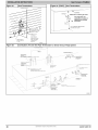
The 4-way multipoise Category IV condensing furnace is CSA
design-certified
as a direct (2-pipe) furnace. (See Figure 3)
The furnace is factory-shipped
for use with natural gas. The
furnace can be converted in the field for use with propane gas
when a factory-supplied
conversion kit is used. Refer to the
furnace rating plate for conversion kit information.
This furnace is not approved for installation in mobile homes,
recreational vehicles, or outdoors.
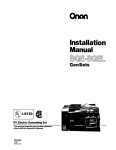
This furnace is designed for minimum continuous return-air
temperature of 60°F (15°C) db or intermittent operation down to
55°F (15°C) db such as when used with a night setback
thermostat. Return-air temperature must not exceed 80°F
(27°C) db. Failure to follow these return-air temperature limits
may affect reliability of heat exchangers, motors, and controls
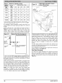
(See Figure 1)
The furnace should be sized to provide 100 percent of the
design heating load requirement plus any margin that occurs
because of furnace model size capacity increments. Heating
load estimates can be made using approved methods available
from Air Conditioning Contractors of America (Manual J);
American
Society
of
Heating,
Refrigerating,
and
Air-Conditioning
Engineers; or other approved engineering
methods. Excessive oversizing of the furnace could cause the
furnace and/or vent to fail prematurely.
For accessory installation details, refer to the applicable
instruction literature.
NOTE: Remove all shipping materials,
literature before operating the furnace.
MAX 80°F/27°C
_AIR
CLEARANCE
In(mm)
0
POSITION
13.
I Freeze Protection and Return Air
Temperature
Figure 1
parts assemblies
and
32 ° F/0 ° C MINIMUM INSTALLED
AMBIENT OR FREEZE
PROTECTION REQUIRED
J
Codes and Standards
Follow all national and local codes and standards in
addition to these instructions. The installation must comply
with regulations of the serving gas supplier, local building,
heating, plumbing, and other codes. In absence of local codes,
the installation must comply with the national codes listed
below and all authorities having jurisdiction.
In the United States and Canada, follow all codes and
standards for the following:
MAX 80°F/27°C
Safety
•
US: National Fuel Gas Code (NFGC) NFPA
54-2009/ANSI Z223.1-2009 and the Installation
Standards, Warm Air Heating and Air Conditioning
Systems ANSI/NFPA 90B
•
CANADA: National Standard of Canada, Natural Gas
and Propane Installation Code (NSCNGPIC)
CAN/CSA B149.1-2010
General Installation
•
US: NFGC and the NFPA 90B. For copies, contact the
National Fire Protection Association Inc.,
Batterymarch Park, Quincy, MA 02269; or for only the
NFGC contact the American Gas Association, 400 N.
Capitol, N.W., Washington DC 20001.
•
CANADA: NSCNGPIC. For a copy, contact Standard
Sales, CSA International, 178 Rexdale Boulevard,
Etobicoke (Toronto), Ontario, M9W 1R3, Canada.
Combustion
and Ventilation
Air
US: Section 9.3 of the NFPA54/ANSI Z223.1-2009,
Air for Combustion and Ventilation
CANADA: Part 8 of the CAN/CSA B149.1-2010,
Venting Systems and Air Supply for Appliances
4
Specificati .....
bject to change without
notice.
440 01 4201 01
Duct Systems
•
US and CANADA: Air Conditioning Contractors
Association (ACCA) Manual D, Sheet Metal and Air
Conditioning Contractors National Association
(SMACNA), or American Society of Heating,
Refrigeration, and Air Conditioning Engineers (ASHRAE)
2005 Fundamentals Handbook Chapter 35.
Acoustical
Duct
•
Lining and Fibrous Glass
1.
Disconnect
all power to the furnace.
Multiple
disconnects may be required. DO NOT TOUCH THE
CONTROL OR ANY WIRE CONNECTED TO THE
CONTROL PRIOR TO DISCHARGING YOUR BODY'S
ELECTROSTATIC CHARGE TO GROUND.
2.
Firmly touch the clean, unpainted, metal surface of the
furnace chassis which is close to the control. Tools held
in a person's hand during grounding will be satisfactorily
discharged.
After touching the chassis, you may proceed to service
the control or connecting wires as long as you do nothing
to recharge your body with static electricity (for example;
DO NOT move or shuffle your feet, do not touch
ungrounded objects, etc.).
If you touch ungrounded objects (and recharge your
body with static electricity), firmly touch a clean,
unpainted metal surface of the furnace again before
touching control or wires.
Use this procedure for installed and uninstatled
(ungrounded) furnaces.
Before removing a new control from its container,
discharge your body's electrostatic charge to ground to
protect the control from damage. If the control is to be
installed in a furnace, follow items 1 through 4 before
bringing the control or yourself in contact with the
furnace. Put all used and new controls into containers
before touching ungrounded objects.
An ESD service kit (available from commercial sources)
may also be used to prevent ESD damage.
3.
US and CANADA: current edition of SMACNA, NFPA
90B as tested by UL Standard 181 for Class I Rigid Air
Ducts
4.
Gas Piping and Gas Pipe Pressure
Testing
•
U.S.A.: NFPA 54/ANSI Z223.1-2009, NFGC; Chapters
5, 6, 7, and 8 and national plumbing codes.
•
Parts 4, 5, 6 and
CANADA: CAN/CSA-B149.1-2010,
9.
In the state of Massachusetts:
•
This product must be installed by a licensed plumber or
gas fitter.
•
When flexible connectors are used, the maximum
length shall not exceed 36-in. (914 mm).
•
When lever type gas shutoffs are used they shall be
T-handle type.
•
The use of copper tubing for gas piping is not
approved by the state of Massachusetts.
6.
7.
Accessories
See Specification
product.
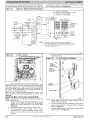
Electrical Connections
Table
•
U.S.A.: National Electrical Code (NEC) ANSI/NFPA
70-2011
•
CANADA: Canadian Electrical Code CSA C22.1
Electrostatic Discharge
Precautions Procedure
5.
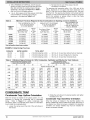
2
QUANTITY
(ESD)
Sheets
for a list of accessories
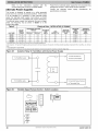
Loose Parts Bag Contents
(shipped
in blower compartment)
COMPONENT NAME
1
Air Intake Pipe Flange
1
Vent Pipe Flange
2
Coupling Flange Gaskets
10
Sharp Tip Screws (Vent and Inlet Flanges)
1
Vent Pipe Coupling
2
1
Vent Pipe Coupling Clamps
Pressure Switch Tube
1
Failure to follow this caution may result in unit com3onent damage.
1
Outlet Choke Plate (used with 40k BTUH
furnaces, only)
Drain Tube Elbow
1
Drain Extension Tube
Electrostatic discharge can affect electronic components. Take precautions during furnace installation and
servicing to protect the furnace electronic control. Precautions will prevent electrostatic discharges from personnel and hand tools which are held during the procedure. These precautions will help to avoid exposing
the control to electrostatic discharge by putting the
furnace, the control, and the person at the same electrostatic potential.
2
1
1
Drain Tube Clamps
Drain Line Grommet
Gas Line Grommet
1
1
Gas Line Knockout Plug
Junction Box Cover
1
Junction Box Base
1
Green Ground Screw
3
1
Blunt Tip Screws (Junction Box)
Thermostat Wire Grommet
FURNACE
RELIABILITY
440 01 4201 01
HAZARD
Specificati .....
bject to change without
notice.
for this
5
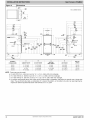
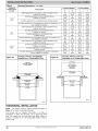
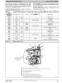
Figure
2
Dimensions
615/14
[17&1]
23_10
NOTE: ALL DIMENSIONS
IN INCH [MM]
[170.1]
•
2611/16_
[678.11
_s3t8
lsTo.ol
251/8_
lea&7]
_A_
OUTLETWIDTH
7/8 _
_
AIR INTAKE
AIRFLOW
¢3_
Cs
CONDENSATE
LOCATION
DRAIN
TRAP
_
_
176.L_
VENT
®
®
Ol
®
117,5]
A
(F/G9MAC)
FURNACE SIZE
6
CABINET WIDTH
OUTLET
C
WIDTH
D
SHIP W_
BOTTOM
INLET WIDTH
AIR INTAKE
LB (KG)
17-1/2
(445)
15-7/8 (403)
16 (406)
8 3/4 (222)
154 (69)
80,000
17-1/2
(445)
15-7/8 (403)
16 (406)
8 3/4 (222)
164 (73)
19-3/8 (492)
19-1/2 (495)
10 1/2 (267)
179(80)
22-7/8 (581)
23 (584)
12 1/4 (311)
203 (91)
120,000
a.
b.
c.
d.
B
[17.5]
60,000
100,000
NOTE:
BOTTOM RETURN
WIDTH
_ .
21 (533)
24-1/2
(622)
Doors may vary by model.
For 800 CFM 16-in. (406 mm) round or 14 ½ x 12-in. (368 x 305 mm) rectangle.
For 1200 CFM 20-in. (508mm round of 14 ½ x 19 ½-in. (368 x 495 mm) rectangle.
For 1600 CFM 22-in. (559 mm) round or 14 ½ x 22 1/16-in. (368 x 560 mm) rectangle.
For airflow requirements above 1800 CFM, see Air Delivery table in Installation Instructions for specific use of single side
inlets. The use of both side inlets, a combination of 1 side and the bottom, or the bottom only return air openings may be
required for airflow requirements above 1800 CFM at 0.5 in. w.c. ESP
Specificati .....
bject to change without
notice.
440 01 4201 01
Location
PERSONAL
HAZARD
be located close to the chimney or vent and attached to an
air distribution system. Refer to Air Ducts section.
be provided ample space for servicing and cleaning.
Always comply with minimum fire protection clearances
shown in Table 1 or on the furnace clearance to
combustible construction label.
INJURY AND/OR PROPERTY DAMAGE
Improper use or installation of this furnace may result in
3remature furnace component failure. This gas furnace
may be used for heating buildings under construction
3rovided that:
-The furnace is permanently installed with all electrical
wiring, piping, venting and ducting installed according to
these installation instructions. A return air duct is
3rovided, sealed to the furnace casing, and terminated
outside the space containing the furnace. This prevents
a negative pressure condition as created by the
circulating air blower, causing a flame rollout and/or
drawing combustion products into the structure.
-The furnace is controlled by a thermostat. It may not be
"hot wired" to provide heat continuously to the structure
without thermostatic control.
-Clean outside air is provided for combustion. This is to
minimize the corrosive effects of adhesives, sealers and
other construction materials. It also prevents the
entrainment of drywall dust into combustion air, which
can cause fouling and plugging of furnace components.
-The temperature of the return air to the furnace is
maintained between 55°F (13°C) and 80°F (27°C), with
no evening setback or shutdown. The use of the furnace
while the structure is under construction is deemed to be
intermittent operation per our installation instructions.
-The air temperature rise is within the rated rise range on
the furnace rating plate, and the gas input rate has been
set to the nameplate value.
CARBON MONOXIDE
DAMAGE HAZARD
POISONING
/ COMPONENT
Failure to follow this warning could result in personal injury or death and unit component damage.
Corrosive or contaminated air may cause failure of parts
containing flue gas, which could leak into the living
space. Air for combustion must not be contaminated by
halogen compounds, which include fluoride, chloride,
bromide, and iodide. These elements can corrode heat
exchangers and shorten furnace life. Air contaminants
are found in aerosol sprays, detergents, bleaches, cleaning solvents, salts, air fresheners, and other household
products. Do not install furnace in a corrosive or contaminated atmosphere. Make sure all combustion and circulating air requirements are met, in addition to all local
codes and ordinances.
The following types of furnace installations
may require
OUTDOOR AIR for combustion due to chemical exposures:
•
Commercial buildings
•
Buildings with indoor pools
•
Laundry rooms
•
Hobby or craft rooms, and
•
Chemical storage areas
If air is exposed to the following substances, it should not be
used for combustion air, and outdoor air may be required for
combustion:
-The filters used to clean the circulating air during the
construction
process must be either changed or
thoroughly cleaned prior to occupancy.
•
•
•
Chlorine based swimming pool chemicals
-The furnace, ductwork and filters are cleaned as
necessary to remove drywall dust and construction
debris from all HVAC system components
after
construction is completed.
•
Water softening chemicals
•
•
De-icing salts or chemicals
Carbon tetrachloride
•
•
Halogen type refrigerants
Cleaning solvents (such as perchloroethylene)
•
Printing inks, paint removers, varnishes, etc.
•
Hydrochloric acid
General
•
Cements and glues
These furnaces are shipped with the following materials to
assist in proper furnace installation. These materials are
shipped in the main blower compartment.
See Table 2 for loose parts bag contents.
This furnace must:
•
Antistatic fabric softeners for clothes dryers
•
Masonry acid washing materials
-Verify proper furnace operating conditions including
ignition, gas input rate, air temperature rise, and venting
according to these installation instructions.
•
•
be installed so the electrical components are protected
from water.
not be installeddirectly on any combustible material other
than
wood
flooring
(refer
to
SAFETY
CONSIDERATIONS).
440 01 4201 01
Specificati .....
Permanent wave solutions
Chlorinated waxes and cleaners
All fuel-burning
equipment must be supplied with air for fuel
combustion. Sufficient air must be provided to avoid negative
pressure in the equipment room or space. A positive seal must
be made between the furnace cabinet and the return-air duct
to prevent pulling air from the burner area.
bject to change without
notice.
7
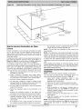
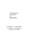
Figure3
1MultipoiseOrientations
AIRFLOW
THE BLOWER iS
LOCATED BELOW THE
BURNER SECTION, AND
CONDiTiONED AIR iS
DISCHARGED
UPWARD.
THE BLOWER iS LOCATED
TOTHE RIGHT OFTHE
BURNER SECTION, AND
AIR CONDiTiONED AiR iS
DISCHARGED TO THE LEFT.
I
HORIZONTAL
RIGHT/AIFF_LQW
THE BLOWER iS
THE BLOWER iS
LOCATED ABOVE THE
LOCATED TO THE LEFT
OF THE BURNER SECTION,
AND CONDiTiONED AiR iS
DISCHARGED TO THE RIGHT.
BURNER SECTION, AND
CONDiTiONED AiR iS
DISCHARGED
DOWNWARD
AIRFLOW
FIRE, INJURY OR DEATH HAZARD
FIRE HAZARD
Failure to follow this warning could result in personal injury, death and/or property damage.
Failure to follow this warning could result in personal injury, death and/or property damage.
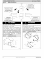
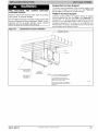
When the furnace is installed in a residential garage, the
burners and ignition sources must be located at least
18-in. (457 mm) above the floor. The furnace must be
located or protected to avoid damage by vehicles. When
the furnace is installed in a public garage, airplane
hangar, or other building having a hazardous atmosphere, the furnace must be installed in accordance with
the NFPA 54/ANSI
Z223.1-2009
or CAN/CSA
B149.1-2010. (See Figure 4)
Do not install the furnace on its back or hang furnace with
control compartment facing downward. Safety control
operation will be adversely affected. Never connect return-air ducts to the back of the furnace. (See Figure 5)
Figure 4
Figure 5
_Prohibited
Installations
1Installation in a Garage
BACK
BA(
18-1N. (457.2 mm)
MINIMUM
TO BURNERS
A10494
A93044
8
Specificati .....
bject to change without
notice.
440 01 4201 01
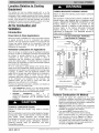
Location Relative to Cooling
Equipment
The cooling coil must be installed parallel with, or on the
downstream side of the unit to avoid condensation in the heat
exchangers. When installed parallel with the furnace, dampers
or other flow control must prevent chilled air from entering the
furnace. If the dampers are manually operated, they must be
equipped with means to prevent operation of either unit unless
the damper is in the full-heat or full-cool position.
Ventilation
Introduction
Combustion
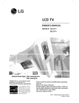
Figure
6
result
in personal
/T_
1 SQ IN.
,
TO _
/
OUTDOORS]
PER 2000
BPER4000
.......
D
12" MAX
1 SQIN.
_
"_'.[
,
t
12_,X (305mrn)
VENT
THROUGH
ROOF
_
BTUH*
1
1 SO IN.
PER
4000
BTUH*
8
DUCTS
TO
OUTDOORS
p_
8
SO IN.
PER
4000
BTUH*
1 SQ IN.
PER 2000
BTUH*
f
(305mm)
l
12" MAX
I
I
]
01ROULATING
12_ X (305mm)
12" MAX
I I (a0_mm/
AIR DUCTS
DuL_JcT'_'_,,_
TO
OUTDOORS
1
1 SQ IN.
PER 4000
BTUH*
*Minimum dimensions of 3-in.
NOTE:Use any of the following combinations
of open_ngs:
A&B
C&D
D&E
F&G
A03174
Outdoor
HAZARD
Failure to follow this caution may result in furnace
damage.
Air for combustion must not be contaminated by halogen
compounds, which include fluoride, chloride, bromide,
and iodide. These elements
can corrode heat
exchangers and shorten furnace life. Air contaminants
are found in aerosol sprays, detergents, bleaches,
cleaning solvents, salts, air fresheners, and other
household products.
Specificati .....
and for
Dilution
for Outdoors
lAir
Combustion,
Ventilation,
DUCTS
(3O5mm)
440 01 4201 01
could
The operation of exhaust fans, kitchen ventilation
fans,
clothes dryers, attic exhaust fans or fireplaces
could
create a NEGATIVE
PRESSURE
CONDITION
at the
Air Applications
When the furnace is installed using the ventilated combustion
air option, the attic or crawlspace must freely communicate with
the outdoor to provide sufficient air for combustion. The
combustion
air pipe cannot be terminated
in attics or
crawlspaces that use ventilation fans designed to operate
during the heating season. If ventilation fans are present in
these areas, the combustion air pipe must terminate outdoors
as a Direct Vent/2-Pipe system.
All air for combustion is piped directly to the furnace from a
space that is well ventilated with outdoor air (such as an attic or
crawlspace) and the space is well isolated from the living space
or garage.
In addition, other gas appliances installed in the
space with the furnace may require outside air for combustion.
Follow the guidelines below to insure that the roof or
crawlspace walls have sufficient free area to provide sufficient
air for combustion and ventilation for the furnaces. The
guidelines below can be used to insure that other gas
appliances have sufficient air for combustion.
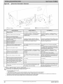
Provisions for adequate combustion, ventilation, and dilution air
must be provided in accordance with:
•
U.S. Installations: Section 9.3 of the NFPA 54/ANSI
Z223.1-2009 , Air for Combustion and Ventilation and
applicable provisions of the local building codes.
•
Canadian
Installations:
Part
8
of
CAN/CSA-B149.1-2010,
Venting Systems and Air
Supply for Appliances
and all authorities
having
jurisdiction.
FURNACE CORROSION
this warning
Applications
When the furnace is installed as a direct vent (2-pipe) furnace,
no special provisions for air for combustion are required.
However, other gas appliances installed in the space with the
furnace may require outside air for combustion. Follow the
guidelines below to insure that other gas appliances have
sufficient air for combustion.
Ventilated
Failure to follow
injury or death.
furnace.
Make-up
air MUST
be provided
for the
ventilation
devices, in addition to that required by the
furnace.
Refer to the Carbon
Monoxide
Poisoning
Hazard
warning
in the venting
section
of these
instructions
to determine
if an adequate
amount
of
make-up
air is available.
Air for Combustion and
Direct Vent (2-Pipe)
CARBON MONOXIDE POISONING HAZARD
bject to change without
Combustion
Air Method
1.
Provide the space with sufficient air for proper
combustion, ventilation, and dilution of flue gases using
permanent horizontal or vertical duct(s) or opening(s)
directly communicating with the outdoors or spaces that
freely communicate with the outdoors.
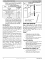
2. Figure 6 illustrates how to provide TWO OUTDOOR
OPENINGS, one inlet and one outlet combustion and
ventilation air openings to the outdoors.
a. One opening MUST commence within 12-in.
(300 mm) of the ceiling and the second opening
MUST commence within 12-in. (300 mm) of the floor.
b. Size openings and ducts per Figure 6 and Table 3.
c. TWO HORIZONTAL DUCTS require 1 square inch
(25.4 square mm) of free area per 2,000 Btuh (1,100
mm2/kW) of combined input for all gas appliances in
the space per Figure 6 and Table 3.
notice.
9
d. TWO OPENINGS OR VERTICAL DUCTS require 1
square inch (25.4 square mm)of free area per 4,000
Btuh (550 mm2/kW) for combined input of all gas
appliances in the space per Figure 6 and Table 3.
3. ONE OUTDOOR OPENING requires:
a. 1 sq. in. (25.4 square mm)of free area per 3,000 Btuh
(734 mm2/kW) for combined input of all gas
appliances in the space per Table 3 and
Table
3
Minimum
Free Area
TWO HORIZONTAL
Required
DUCTS
for Each Combustion
(BTUH)
Free Area of
Opening and Duct
Sq. In (Sq. mm)
40,000 *
60,000
80,000
100,000
120,000
140,000"
• Not all families
20 (12904)
30 (19355)
40 (25807)
50 (32258)
60 (38709)
70 (45161)
have these models.
EXAMPLE: Determining
FURNACE
Air Opening
SINGLE DUCT OR OPENING
(1 SQ. IN./2,000 BTUH)
(1,100 SQ. MM/KW)
FURNACE
INPUT
b. Not less than the sum of the areas of all vent
connectors in the space.
The opening shall commence within 12-in. (300 mm) of the
ceiling. Appliances in the space shall have clearances of at
least 1-in. (25 mm) from the sides and back and 6-in. (150 mm)
from the front. The opening shall directly communicate with the
outdoors or shall communicate through a vertical or horizontal
duct to the outdoors or spaces (crawl or attic) that freely
communicate with the outdoors.
(1 SQ. IN./3,000 BTUH)
(734 SQ. MM/KW)
Round
Duct
In. (mm)
Dia
Free Area of Opening and Duct
Sq. In (Sq. mm)
5 (127)
6 (152)
7 (178)
8 (203)
9 (229)
10 (254)
14 (8696)
20 (13043)
27 (17391)
34 (21739)
40 (26087)
47 (30435)
TWO OPENINGS OR
VERTICAL DUCTS
(1 SQ. IN./4,000 BTUH)
(550 SQ. MM/KW)
Round
Duct
In. (mm)
Dia
5
5
6
7
7
8
or Duct to Outdoors
(127)
(127)
(152)
(178)
(178)
(203)
Free Area of Opening and Duct
Sq. In (mm)
Round Duct
In. (mm)
Dia.
10 (6452)
15 (9678)
20 (12904)
25 (16130)
30 (19355)
35 (22581)
4
5
5
6
6
7
(102)
(127)
(127)
(152)
(152)
(178)
Free Area
WATER HEATER
TOTAL INPUT
100,000
60,000
+
+
30,000
40,000
=
=
(130,000 divided by 4,000)
(100,000 divided by 3,000)
=
=
32.5 Sq. In. for each two Vertical Ducts or Openings
33.3 Sq. In. for each Single Duct or Opening
80,000
+
30,000
=
(110,000 divided by 2,000)
=
55.0 Sq. In. for each two Horizontal Ducts
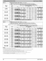
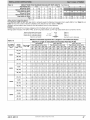
Table
4
Minimum Space Volumes for 100% Combustion,
Ventilation
and Dilution Air from Outdoors
OTHER THAN FAN-ASSISTED TOTAL
FAN-ASSISTED TOTAL
(1,000'S BTUH GAS INPUT RATE)
(1,000'S BTUH GAS INPUT RATE)
30
40
50
40
60
80
100
120
AOH
Space Volume Ft 3 (M3)
1,050
1,400
1,750
1,400
1,500
2,000
2,500
3,000
0.60
(29.7)
(39.6)
(49.5)
(39.6)
(42.5)
(56.6)
(70.8)
(84.9)
140
3,500
(99.1)
0.50
1,260
(35.6)
1,680
(47.5)
2,100
(59.4)
1,680
(47.5)
1,800
(51.0)
2,400
(67.9)
3,000
(84.9)
3,600
(101.9)
4,200
(118.9)
0.40
1,575
(44.5)
2,100
(59.4)
2,625
(74.3)
2,100
(59.4)
2,250
(63.7)
3,000
(84.9)
3,750
(106.1 )
4,500
(127.3)
5,250
(148.6)
0.30
2,100
(59.4)
2,800
(79.2)
3,500
(99.1)
2,800
(79.2)
3,000
(84.9)
4,000
(113.2)
5,000
(141.5)
6,000
(169.8)
7,000
(198.1 )
0.20
3,150
(89.1)
4,200
(118.9)
5,250
(148.6)
4,200
(118.9)
4,500
(127.3)
6,000
(169.8)
7,500
(212.2)
9,000
(254.6)
10,500
(297.1)
0.10
0.00
6,300
(178.0)
NP
8,400
(237.8)
NP
10,500
(297.3)
NP
8,400
(237.8)
NP
9,000
(254.6)
NP
12,000
(339.5)
NP
15,000
(424.4)
NP
18,000
(509.2)
NP
21,000
(594.1)
NP
NP = Not Permitted
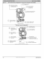
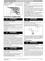
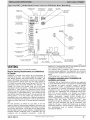
CONDENSATE
Condensate
TRAP
Trap-Upflow
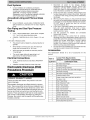
When the furnace is installed in the upflow position, it is not
necessary to relocate the condensate trap or associated
tubing.
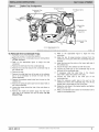
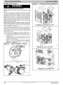
Refer to Figure7
for upflow condensate
trap
information. Refer to Condensate Drain section for information
how to install the condensate drain.
1. Loosen the clamp around the inlet of the vent elbow on
the inducer.
10
2. Rotate the vent elbow to the desired position and tighten
the clamp 15 in.-Ibs.
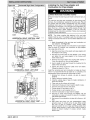
Orientation
Specificati .....
Condensate
Trap-Downflow
Orientation
When the furnace is installed in the downflow
factory-installed trap will be located at the upper
the collector box. When the furnace is installed in
orientation, the factory-installed
trap must be
proper condensate drainage.
bject to change without
notice.
position, the
left corner of
the downflow
relocated for
440 01 4201 01
ii:ii! ii i iit
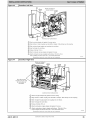
Figure 7
Upflow
¸
Trap Configuration
Vent Pipe Clamp
Vent Elbow Clamp
Condensate Trap
Relief Port
Elbow
Plugs
Collector Box
Plug
p
Relief Port
Pressure Switch
Port
Outlet
UPFLOW TRAP CONFIGURATION
MODULATING
Representative
To Relocate
the Condensate
drawing
only some
3. Refer to the
conversion.
appropriate
trap and tubing before
figure
to
begin
the
trap
4. Remove the relief tube from the condensate trap.
5. Remove the screw that secures the condensate
the collector box.
9. Remove the pressure switch tube from the stand-offs
the inducer assembly
on
10. Loosen the clamp around the inlet of the vent elbow on
the inducer.
11. Remove the middle and bottom plugs from the lower
right side of the collector box and set aside. Do Not
Discard Plugs.
Specificati .....
appropriate
figure
to
begin
the
trap
13. Install the two (2) plugs previous removed from the
collector box in the ports where the condensate trap was
removed.
14. Install the trap over the ports on the lower right side of
the collector box.
15. Secure the trap to the collector box with the screw.
trap to
6. Remove the trap.
7. Remove the relief tube from of the port on the collector
box. It is not necessary to remove the hose from the
inducer assembly.
8. Remove the pressure switch tube from the port on the
collector box.
440 01 4201 01
Al1306
models may vary in appearance.
12. Refer to the
conversion.
Trap:
1. Orient the furnace in the downflow position.
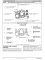
2. Figure 8 shows the condensate
and after relocation.
UN{TS
16. Connect the relief tube to the condensate
relief port of the condensate trap.
trap to the
17. If necessary, slide the relief tube in the
stand-offs to adjust the position of the tube.
inducer
18. Connect the relief tube to the relief port
condensate trap.
19. Route the pressure switch tube to the port
collector box next to the condensate trap. Trim
excess tube to avoid sags or kinks in the tube.
20. Rotate the vent elbow to the desired position and
the clamp 15 in.-Ibs.
21. Refer to Condensate Drain section for information
install the condensate drain.
of
bject to change without
notice.
the
on the
off any
tighten
how to
11
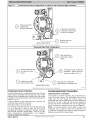
Figure
8
I Unconverted
Factory
Configuration
as viewed
in the Downflow
orientation
A
_
emove
pressure switch.
switch tube from
front
of pressure
Remove relief tube from relief
port on condensate trap.
(_
collector
emove trap
box. from
(_
Loosen
clamp on inlet
to vent elbow.
Remove tube from
relief port.
-__
(MODULATING UNITS)
Remove middle and bottom plugs.
DO NOT DISCARD.
Representative
drawing
only some models
may vary in appearance.
Downflow Trap Configuration
:_7/
"\, Route tube through
inducer stand-offs
\
Install plugs on
open ports on
collect(._r box.
/
/
Trim excess tube.
Connect pressure switch
tube to port on collector box.
/
/
f
Attach condensate trap
with screw to collector
box.
Connect relief tube
port on collector box.
'\
j
Rotate elbow to
desired F_sition and
tighten clamp t_,
15 lb.-in.
/
(MODULATING
UNITS)
/
/
/
Slide tube in stand_ffs
/
Connect relief tube to
relief port on condensate
trap.
/
/- _, Align condensate trap
.\ 2/: over middle and bottom
ports of collector box.
/
--/
t_; adjust length.
[ Representative
drawing
only some models
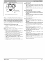
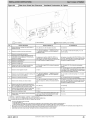
Condensate Trap-Horizontal
Orientation
When the furnace is installed in the horizontal right position, the
factory-installed trap will be located at the bottom left corner of
the collector box. When the furnace is installed in the horizontal
left position, the factory-installed trap will be located at the top
12
Specificati .....
may vary in appearance.
]
Al1277
of the collector box. The trap must be repositioned on the
collector box for proper condensate drainage.
When the furnace is installed as a direct vent furnace, a field
supplied, accessory Horizontal Installation Kit is required for all
horizontal installations. The kit contains a rubber casing
grommet designed to seal between the furnace casing and the
condensate trap. (See Figure 9)
bject to change without
notice.
440 01 4201 01
Figure
9
1Drain
10. Remove the trap.
Trap Grommet
Horizontal Left only:
1. Remove the relief tube from of the port on the collector
box. It is not necessary to remove the hose from the
inducer assembly.
2. Remove the pressure switch tube from the port on the
collector box.
3. Remove the pressure switch tube from the stand-offs
the inducer assembly.
on
For Horizontal Right only:
1. The pressure switch tube location is not modified.
trap
Horizontal
2. Loosen the clamp around the inlet of the vent elbow on
the inducer.
3. Remove the plugs from the collector box and set aside.
Do Not Discard Plugs.
For Horizontal Left only:
Drain Trap Grommet
Al1348
NOTE: The condensate trap extends below the side of the
casing in the horizontal position. A minimum of 2-in. (51 mm) of
clearance is required between the casing side and the furnace
platform for the trap to extend out of the casing in the horizontal
position. In areas where the ambient temperature will fall below
32 ° F. (O°C), a field-supplied condensate freeze protection kit is
required. See Product Data for current kit offering. Follow the
instructions included in the kit.
To Relocate
the Condensate
Trap:
1. Remove the knockout in the casing for the casing
grommet.
2. Install the grommet in the casing.
NOTE:
This
applications.
grommet
is
only
required
for
direct-vent
4. Allow for 2-in. (51 mm) of clearance underneath
furnace for the condensate trap and drain line.
the
5. Figure 10 shows the condensate trap and tubing before
and after relocation in the horizontal left position.
6. Figure 11 shows the condensate trap and tubing before
and after relocation in the horizontal right position.
appropriate
figure
to
begin
the
trap
8. Remove the relief tube from the condensate trap.
9. Remove the screw that secures the condensate
the collector box.
440 01 4201 01
For Horizontal Right only:
1. Remove the plug to the right of the condensate trap.
2. Refer to the
conversion.
appropriate
figure
to
begin
the
Specificati .....
trap
3. Install the plugs previous removed from the collector box
in the ports where the condensate trap was removed.
4. Install the trap over the ports on the lower side of the
collector box.
5. Secure the trap to the collector box with the screw.
6. Connect the relief tube to the condensate
relief port of the condensate trap.
trap to the
7. If necessary, slide the relief tube in the
stand-offs to adjust the position of the tube.
3. Orient the furnace in the desired position.
7. Refer to the
conversion.
1. Remove the middle and right plug from the ports at the
bottom of the collector box.
For Horizontal
inducer
Left only:
1. Connect the relief
condensate trap.
tube
to
the
relief
port
2. Connect the pressure switch tube to the port
collector box next to the condensate trap. Trim
excess tube to avoid sags or kinks in the tube.
3. Rotate the vent elbow to the desired position and
the clamp 15 in.-Ibs.
4. Refer to Condensate Drain section for information
install the condensate drain.
of
the
on the
off any
tighten
how to
trap to
bject to change without
notice.
13
Figure 10
1Unconverted
Factory Configuration
as viewed in the Horizontal Left orientation
Remove trap from
collector box.
If alternate
vent position
is required,
loosen clamp
Remove relief tube
on vent elbow inlet,
from relief port on
condensate
trap.
Remove pressure switch tube
from port on collector box.
Remove relief tube
from port on collector
box.
Remove middle and right
plug from collector box.
(MODULATING
Representative
drawing
only
UNITS)
some models may vary in appearance.
Horizontal Left Trap Configuration
Install plugs in open
ports on collector box.
Rotate elbow to
desired position and
torque clamp on inlet
15 Ib.-in.
Connect relief tube to
port on collector
box.
Slide relief tube in
stand-offs
length.
to adjust
Attach condensate
Trim excess tube.
trap to collector box
with screw.
Route pressure switch tube
underneath relief tube and
connect to port on collector
Align trap over middle
and right-hand port on
collector box.
box.
Connect relief tube to
relief port on condensate
trap.
(MODULATING UNITS)
Al1282
Representative
14
drawing
Specificati .....
only
some models may vary in appearance.
bject to change without
notice.
440 01 4201 01
iiiii! ii i iit
Figure 11
_Unconverted
(_)
¸
Factory Configuration
as viewed in the Horizontal Right orientation
collector
emove box.
plug from
DO NOT DISCARD.
If alternate vent position
is required, loosen clamp
on inlet of vent elbow.
\
Remove
collector
(MODULATING UNITS)
Representative
drawing
Horizontal
only some models
trap from
box.
may vary in appearance.
Right Trap Configuration
Slide relief tube in
stand-offs to adjust
length.
(_
tottach
collector
box with trap
condensate
screw.
(_)
Install
in open
port on plug
collector
box.
Vent elbow shown in alternate
orientation.
Tighten clamp on
inlet to vent elbow 15 lb.-in.
Align trap over middle and
right-hand port on collector
box.
(MODULATING UNITS)
Al1281
Representative
Condensate
drawing
only some models
Condensate
Drain Protection
Freezing condensate left in condensate trap and drain line may
cause cracks, and possible water damage may occur. Freeze
protection of the condensate trap is required when the furnace
is installed in the horizontal position and the attic temperature is
below 32 ° F (0° C).
If freeze protection for the condensate trap is required, use
condensate freeze protection accessory.
See Product Data for current kit offering.
The remaining condensate drain line can be protected by using
a 3 to 6 watt per ft. (.3M) at 120v and 40°F (4.4°0)
self-regulating, shielded, and waterproof heat tape. Wrap field
drain pipe with heat tape, approximately 1 wrap per ft. (.3M).
Follow manufacturer's
recommendations
and installation
instructions supplied with heat tape.
440 01 4201 01
may vary in appearance.
Specificati .....
Upflow/Downflow
Drain Connection
Orientation
In the Upflow or Downflow orientation, the condensate trap is
inside the furnace casing. The condensate drain must be
routed from the trap through the furnace casing. The
condensate drain can be routed through the left or right side of
the casing. (The left or right side is as you are viewing the
furnace.) The furnace condensate drain can be connected to
the Air Conditioning condensate drain as shown in Figure 12.
NOTE: On narrower casing, it may be easier to remove the
condensate trap, connect the drain line components and
re-install the condensate trap. Read the steps thoroughly to
familiarize yourself with the required steps.
bject to change without
notice.
15
Figure
12
6. Remove the formed grommet on the tube by cutting the
tube along the vertical line located about 1-in. away from
the formed grommet. (See Figure 13)
Example of Field Drain Attachment
Figure
OPEN STAND
PIPE FOR
13
A/C OR
HUMIDIFIER
DRAIN
_Modify
Drain Tube
Cut and removeformed end of
drain tube for left sideand horizontal
drain connection
\
U
_'-=TEE
TO OPEN
DRAIN
RIGHT SIDE DRAIN ELBOW
Al1276
Al1388
For Right Side Condensate Drain:
1. Remove the 7/8-in. knock-out from the right side of the
7. Slide a spring clamp 1-in.
drain tube
casing. (See Figure 15)
2. Remove the pre-formed
drain tube
clamps from the loose parts bag.
3. Slide a spring clamp 1-in.
drain tube.
8. With the bend in the tube oriented horizontally and plain
end of the tube pointing away from you, insert the 1/2-in
CPVC pipe into the other end of the drain tube. Rotate
the tube so the offset in the tube points away from you.
Slide a spring clamp over the open end of the 1/2-in.
CPVC tube and secure the cut end of drain tube to the
pipe. (See Figure 14)
and two spring
down the plain end of the
4. From inside the casing, insert the formed grommet end
of the tube through the 7/8-in. knockout in the casing.
5. Pull the tube through the casing from the outside until it is
seated in the knockout
6. Attach the plain end of the drain tube to the outlet stub
on the drain trap. Secure the drain tube to the trap with
the spring clamp.
7. Slide a spring clamp over the open end of the drain tube
outside the casing.
8. Open the spring clamp and connect a field-supplied
1/2-in. CPVC street elbow to the open end of the drain
tube.
down the plain end of the
Figure
14
_Drain
Trap Connection
Attach
Field supplied
1/2"CPVC
Cut formed
end off
condensate
drain tube
Connect
_7ulPl_ng2t,,d;n ainextension,
short end _
TRAP,
DRAIN
ELBOW
WITH
Modified
1. For left side condensate drainage, the drain line is routed
from the condensate trap, behind the inducer and out
through the left side of the casing. A pre-formed "Z" pipe
is provided in the loose parts bag shipped with the
furnace. The "Z" pipe is long enough to extend out of the
casing on the 14 3/16-in. (360 mm) wide furnace. Larger
casings will require a field supplied CPVC pipe and to
extend the drain line out of the furnace.
Field supplied
CPVC to drain
\
_'_
\v
DISCHARGE
drain tube
il ]
PIPE
connect
to
trap and "Z" pipe
1/2"
Easing grommet
2. The "Z" pipe is connected to the condensate trap by
modifying the formed rubber drain tube. Connect the
drain line as shown below:
Specificati .....
trap
\
of"Z"pipetomodified\_
condensate
16
tube to condensate
\
9. Connect additional 1/2-in. CPVC piping to a condensate
pump approved for use with acidic furnace condensate
or to a code-approved drain.
For Left Side Condensate
Drain Connection:
3. Remove the knock-out from the left side of the casing.
(See Figure 15)
4. Install the grommet for the 1/2-in. CPVC drain line in the
7/8-in. knockout in the casing.
5. Remove the pre-formed drain tube, the offset 1/2-in.
CPVC pipe and two spring clamps from the loose parts
bag.
and Routing
from
parts bag
LEFT SIDE DRAIN
Field-supplied
1/2"CPVC
pipe 17 1/2" 21"and
ROUTED
BEHIND
coupling
& drain
24 1/2"casings
INDUCER
Al1344
9. Prime the bare end of the pipe with CPVC primer.
10. Route the offset pipe behind the inducer assembly and
through the grommet in the casing, if the "Z" pipe is long
enough. If the "Z" pipe is not long enough, continue with
installation.
11. Attach the plain end of the drain tube to the outlet stub
on the drain trap. Secure the drain tube to the trap with
the spring clamp.
bject to change without
notice.
440 01 4201 01
12. If the "Z" pipe does not extend through the casing, slide a
piece of field supplied CPVC through the grommet in the
casing, otherwise, go to Step 17.
13. Cement a 1/2-in. CPVC coupling to the end of the CPVC
pipe.
14. Apply cement to the end of the "Z" pipe connected to the
condensate trap.
15. Connect the field-supplied CPVC pipe to the CPVC pipe
connected to the condensate trap.
16. Cut off excess CPVC pipe outside the casing.
17. Connect additional 1/2-in. CPVC piping to a condensate
pump approved for use with acidic furnace condensate
or to a code-approved drain.
7.
Slide the other spring clamp down the plain end of the
drain tube.
8. Connect additional 1/2-in. CPVC piping to the open end
of the tube.
9. Slide the spring clamp down over the 1/2-in. CPVC pipe.
10. Connect additional 1/2-in. CPVC piping to a condensate
pump approved for use with acidic furnace condensate
or to a code-approved drain.
11. When a condensate pump is not used, slope the pipe
away from the furnace to allow for proper drainage.
Figure
16
J Formed
Tube Grommet
INSTALL CLAMPS ON DRAIN TUBE
ATTACH DRAIN TUBE TO CONDENSATE----/
18. When a condensate pump is not used, slope the pipe
away from the furnace to allow for proper drainage.
DRAIN TRAP
/
PULL DRAIN STUB
THROUGH CASING
Figure
15
_Knockout
Removal
!
0
o_°
¢
yl
Al1305
OPEN SPRING
CLAMP
INSERT FIELD - SUPPLIED
1/2'" CPVC DRAIN PIPE
* CLAMP MAY BE LOCATED
ON OUTSIDE
OF DRAIN TUBE
RIGHT
SIDE DRAIN
INSTALLATION
Al1342
CUT HAZARD
Failure to follow this caution may result in personal injury.
Sheet metal parts may have sharp edges or burrs. Use
care and wear appropriate protective clothing, safety
glasses and gloves when handling parts, and servicing
furnaces.
Horizontal
INSTALLATION
UPFLOW
INSTALLATION
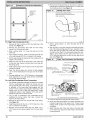
NOTE: The furnace must be pitched forward
Figure 17 for proper condensate drainage.
as shown in
Orientation
1. In the Horizontal orientation, a field supplied accessory
drain trap grommet is required to seal the gap between
the casing and the condensate trap for direct vent
applications only. The condensate trap outlet extends 2
inches (51 mm) below the furnace casing. To allow for
servicing the trap, the condensate drain tube in the loose
parts bag can be modified to make a coupler to allow for
future service of the condensate trap and drain line.
2. Remove the knock-out
side of the casing.
for the condensate
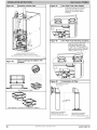
Figure
17
I Furnace
Pitch
Requirements
LEVEL 0-IN. (0 MM) TO
1/2-1N.(13 MM) MAX
MIN 1/4-IN. (6 MM) TO
1/2-1N.(13 MM) MAX
trap in the
3. Install the drain trap grommet in the casing (for direct
vent applications). If necessary, remove the trap, install
the grommet and re-install the trap.
4. Remove the pre-formed drain tube, the offset 1/2-in.
CPVC pipe and two spring clamps from the loose parts
bag.
5. Remove the formed grommet on the tube to create an
elbow or straight connector. (See Figure 16)
6. Connect the cut tube to the outlet of the condensate trap
with 1 spring clamp.
440 01 4201 01
Specificati .....
UPFLOW OR
DOWNFLOW
HORIZONTAL
Al1237
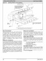
Supply Air Connections
For a furnace not equipped with a cooling coil, the outlet duct
shall be provided with a removable access panel. This opening
shall be accessible when the furnace is installed and shall be of
such a size that the heat exchanger can be viewed for possible
bject to change without
notice.
17
openings using light assistance or a probe can be inserted for
sampling the air stream. The cover attachment shall prevent
leaks.
Connect supply-air
duct to flanges on furnace supply-air
outlet. Bend flange upward to 90 ° with wide duct pliers. (See
Figure 21) The supply-air duct must be connected to ONLY
the furnace supply-outlet-air
duct flanges or air conditioning
coil casing (when used). DO NOT cut main furnace casing side
to attach supply air duct, humidifier, or other accessories. All
accessories MUST be connected to duct external to furnace
main casing.
Leveling
Legs (If Desired)
In upflow position with side return inlet(s), leveling legs may be
used. (See Figure 19) Install field-supplied, 5/16 x 1-1/2 in. (8
x 38 mm) (max) corrosion-resistant
machine bolts, washers
and nuts.
Figure
19
_ Leveling
Legs
5/.
(8ram)
Return Air Connections
1
(44mrn)
FIRE HAZARD
A failure to follow
this
warning
injury, death and/or property
could
cause
13/4"
(44mrn)
personal
damage.
Never connect
return-air
ducts
furnace. Fo ow nstruct ons be ow.
to
the
back
of
(8mrn)
the
5/16"
The return-air duct must be connected to bottom, sides (left or
right), or a combination of bottom and side(s) of main furnace
casing as shown in Figure26,
Figure27
and Figure28,
Bypass humidifier may be attached into unused return air side
of the furnace casing.
Bottom
Return
18
(44mm) 1 3/4"
(44mm)1 3/4'%_.
Air Inlet
These furnaces are shipped with bottom closure panel installed
in bottom return-air opening. Remove this panel when bottom
return air is used. This panel may be used as the bottom
closure of an accessory bottom return air box or discarded. To
remove bottom closure panel, perform the following:
1. Tilt or raise furnace and remove four (4) screws holding
bottom plate. (See Figure 18)
2. Remove bottom plate.
3. Remove bottom closure panel.
4. Reinstall bottom plate and screws.
Figure
(8mm)
I Removing
Bottom
Closure
A89014
NOTE: Bottom closure must be used when leveling legs are
used. It may be necessary to remove and reinstall bottom
closure panel to install leveling legs. To remove bottom closure
panel, see Step 1 in Bottom Return Air Inlet section.
To install leveling legs:
1. Position furnace on its back. Locate and drill a hole in
each bottom corner of furnace.
2.
For each leg, install nut on bolt and then install bolt with
nut in hole. (Install flat washer if desired.)
Install another nut on other side of furnace base. (Install
flat washer if desired.)
Adjust outside nut to provide desired height, and tighten
inside nut to secure arrangement.
Reinstall bottom closure panel if removed.
Panel
i
3.
•d" q
4.
5.
DOWN FLOW INSTALLATION
NOTE: The furnace must be pitched forward
Figure 17 for proper condensate drainage.
Supply
•
PANEL
•
Ltl F004
Side Return Air Inlet
These furnaces are shipped with bottom closure panel installed
in bottom return-air opening. This panel MUST be in place
when only side return air is used.
NOTE: Side return-air openings can be used in UPFLOW and
most HORIZONTAL configurations. Do not use side return-air
openings in DOWNFLOW configuration.
(See
Figure26,
Figure 27 and Figure 28)
18
in
Air Connections
NOTE: For downflow applications, this furnace is approved for
use on combustible flooring when any one of the following
three accessories are used (see Specification sheets for list of
approved accessories):
BOTTOM
CLOSURE
BOTTOM
PLATE
as shown
Specificati .....
bject to change without
Special Base - NAHA01101SB
Cased Coil AssemblyEND4X, ENW4X
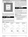
Determine application being installed from Table 5.
Construct hole in floor per Table 5 and Figure 20.
Construct plenum to dimensions specified in Table 5
and Figure 20.
4. Install as shown in Figure 22. If Coil Assembly Part is
used, install as shown in Figure 23.
1.
2.
3.
notice.
440 01 4201 01
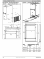
Figure20
Connect supply-air duct to supply-air outlet on furnace. Bend
flange inward past 90 ° with wide duct pliers (See Table 1
Figure 21) The supply-air duct must be connected to ONLY
the furnace supply outlet or air conditioning coil casing (when
used). When installed on combustible material, supply-air duct
must be connected to ONLY the factory-approved
accessory
subbase, or a factory-approved air conditioning coil casing. DO
NOT cut main furnace casing to attach supply side air duct,
humidifier, or other accessories. All accessories MUST be
connected to duct external to furnace casing.
Dimensions
JFloor
andPlenumOpening
Return
Air Connections
FIRE HAZARD
A failure to follow this warning could cause personal
injury, death and/or property damage.
Never connect return-air ducts to the back of the
furnace. Fo ow nstruct ons be ow.
A96283
NOTE: It is recommended that the perforated supply-air duct
flanges be completely removed from furnace when installing
the furnace on a factory-supplied
cased coil. To remove the
supply-air duct flange, use wide duct pliers or hand seamers to
bend flange back and forth until it breaks off. Be careful of
sharp edges. (See Figure 21)
The return-air duct must be connected to return-air opening
(bottom inlet) as shown in Figure 26. DO NOT cut into casing
sides (left or right). Bypass humidifier connections should be
made at ductwork or coil casing sides exterior to furnace. (See
Figure 26)
Bottom
Return
These furnaces are shipped with bottom closure panel installed
in bottom return-air opening. Remove and discard this panel
when bottom return air is used in downflow applications. To
remove bottom closure panel, perform the following:
1.
Tilt or raise furnace and remove four (4) screws holding
bottom plate panel. (See Figure 18)
Remove bottom plate.
Remove bottom closure panel.
Reinstall bottom plate and screws.
CUT HAZARD
Failure
injury.
to follow
this
caution
may
result
Air Inlet
2.
3.
4.
in personal
Sheet metal parts may have sharp edges or burrs. Use
care and wear appropriate
protective
clothing,
safety
glasses and gloves when handling parts, and servicing
furnaces.
Figure
21
JDuct
Flanges
=
UPFLOW
DOWN FLOW
HORIZONTAL
_PERFORATED
DISCHARGE
GE
DUCT
_9_0 T
_
_
YES
YES
YES
i
YES
120°\.
MIN
,\
\
120o',,
YES
MIN
YES
MIN
NO
NO
120 '°_.
NO
A1049_
440 01 4201 01
Specificati .....
bject to change without
notice.
19
Table 5
Opening Dimensions - in. (mm)
FURNACE
CASI NG WIDTH
PLENUM OPENING
A
IN, (mm)
Upflow Applications on Combustible or Noncombustible
(subbase not required)
C
D
21-5/8
(549)
16-5/8
(422)
22-1/4
(565)
15-7/8
(403)
15-1/8
(384)
19
(483)
19
(483)
16-1/2
(419)
16-3/4
(425)
19-5/8
(498)
20-5/8
(600)
15-1/2
(394)
19
(483)
16-1/2
(419)
20
(508)
19-1/2
(495)
21-5/8
(549)
20-1/8
(511)
22-1/4
(565)
19-3/8
(492)
19
(483)
20
(508)
19-5/8
(498)
18-5/8
(473)
19
(483)
20-1/4
(514)
20-5/8
(600)
19
(483)
19
(483)
20
(508)
20
(508)
23
(584)
21-1/8
(537)
23-5/8
(600)
22-1/4
(565)
22-7/8
(581)
19
(483)
23-1/2
(597)
19-5/8
(498)
Downflow applications on Combustible flooring
(subbase required)
22-1/8
(562)
19
(483)
23-3/4
(603)
20-5/8
(600)
Downflow Applications on Combustible Flooring with Coil Assembly or
coil box (subbase not required)
22-1/2
(572)
19
(483)
23-1/2
(597)
20
(508)
Downflow Applications on Noncombustible
(subbase not required)
Flooring
B
16
(406)
17-1/2
(445)
Flooring
Downflow applications on combustible flooring (subbase required)
Downflow Applications
on Combustible Flooring with Coil Assembly or coil
box (subbase not required)
Upflow Applications on Combustible or Noncombustible
(subbase not required)
Downflow Applications on Noncombustible
(subbase not required)
21
(533)
Flooring
Flooring
Downflow applications on combustible flooring
(subbase required)
Downflow Applications
on Combustible Flooring with Coil Assembly or coil
box (subbase not required)
Upflow Applications on Combustible or Noncombustible
(subbase not required)
Downflow Applications on Noncombustible
(subbase not required)
24-1/2
(622)
Figure 22
FLOOR OPENING
APPLICATION
Furnace, Plenum, and Subbase
Installed on a Combustible
Floor
Flooring
Flooring
Figure 23
Furnace, Plenum, and Coil
Assembly
on a Combustible
Floor
FURNACE
FURNACE
(OR COIL CASING
WHEN USED)
CD5 OR CK5
COIL ASSEMBLY
OR KCAKC
COIL'BOX
_
COMBUSTIBLE
FLOORING
--
\
COMBUSTIBLE
FLOORING
SHEET METAL
PLENUM
_.
SUBBASE
SHEET METAL
PLENUM
--
FLOOR
OPENING
FLOOR
OPENING
--
E
A96284
A96285
HORIZONTAL
INSTALLATION
NOTE: The furnace must be pitched forward
Figure 17 for proper condensate drainage.
as shown in
The furnace can be installed horizontally
in an attic or
crawlspace on either the left-hand (LH) or right-hand (RH)
side. The furnace can be hung from floor joists, rafters or
trusses or installed on a non-combustible
platform, blocks,
bricks or pad.
20
Specificati .....
bject to change without
notice.
440 01 4201 01
Suspended Furnace Support
FIRE, EXPLOSION,
AND
POISONING HAZARD
CARBON
The furnace may be supported under the entire length of the
furnace with threaded rod and angle iron. (See Figure 24)
Secure angle iron to bottom of furnace as shown.
MONOXIDE
Failure to follow this warning could result in personal
injury, death, or property damage.
Do not install the furnace on its back or hang furnace with
control compartment facing downward. Safety control
operation will be adversely affected. Never connect
return-air ducts to the back of the furnace.
Figure 24
1Suspended
Platform
Furnace
Support
Construct working platform at location where all required
furnace clearances are met. (See Table 1 and Figure 25) For
furnaces with 1-in. (25 mm) clearance requirement on side, set
furnace on non-combustible
blocks, bricks or angle iron. For
crawlspace installations, if the furnace is not suspended from
the floor joists, the ground underneath furnace must be level
and the furnace set on blocks or bricks.
Furnace Installation
--
COMBUSTION
- AIR
(SEE VENTING
SECTION)
PiPE
VENT
NOTE:
EXTEND
ANGLE
IRON OUT FOR
COIL SUPPORT
HEX
NUT
& WASHER
REQD.
PER
(4)
ROD
NOTES:
ROD
LOCATION
USING
DIMPLE
LOCATORS_
1. A 1 In. (25mm) clearance minimum between
top of furnace and combustible material
I
2. The entire length of furnace must be
supported when furnace is used in horizontal
position to ensure proper drainage.
Al1155
3. Furnace
Refer
shown
to the Venting
is a direct
section
vent
application.
for agowable
vent
configurations.
440 01 4201 01
Specificati .....
bject to change without
notice.
21
Figure
25
I Working
Platform
for Attic
Installation
COMBUSTION
- AIR
PIPE __
VENT
(SEE VENTING SECTION)
(305 mm) MIN HORIZONTAL
PIPE
SECTION IS RECOMMENDED
WITH A
SHORT (5 TO 8 FT / 1.5 TO 2.4 M) VENT
SYSTEM TO REDUCE EXCESSIVE
CONDENSATE
DROPLETS FROM
EXITING THE VENT PIPE.
30" (762 mm)
Min Work Area
MANUAL
ROLLOUT PROTECTION REQUIRED
Install 1.2" x 22" (305 x 559 mm) sheet
metal in front of burner compartment
area.
I
SHUTOFF
/
INDOOR
COIL
CONDENSATE
TRAP
TRAP
NOTE: FURNACE
VENTING
SHOWN AS DIRECT
SECTION
VENT APPLICATION.
FOR ALLOWABLE
REFER
TO THE
VENT CONFIGURATIONS
Al1154
Roll-Out
Protection
Return Air Connections
Provide a minimum 12-in. x 22-in. (305 x 559 mm) piece of
sheet metal for flame roll-out protection in front of burner area
for furnaces
closer than 12-in.
(305 mm) above the
combustible deck or suspended furnaces closer than 12-in.
(305mm) to joists. The sheet metal MUST extend underneath
the furnace casing by 1-in. (25mm) with the door removed.
The bottom closure panel may be used for flame roll-out
protection when bottom of furnace is used for return air
connection. See Figure 25 for proper orientation of roll-out
shield.
Supply
Air Connections
For a furnace not equipped with a cooling coil, the outlet duct
shall be provided with a removable access panel. This opening
shall be accessible when the furnace is installed and shall be of
such a size that the heat exchanger can be viewed for possible
openings using light assistance or a probe can be inserted for
sampling the air stream. The cover attachment shall prevent
leaks.
Connect supply-air
duct to flanges on furnace supply-air
outlet. Bend flange upward to 90 ° with wide duct pliers. (See
Figure 21) The supply-air duct must be connected to ONLY
the furnace supply-outlet-air
duct flanges or air conditioning
coil casing (when used). DO NOT cut main furnace casing side
to attach supply air duct, humidifier, or other accessories. All
accessories MUST be connected to duct external to furnace
main casing.
22
Specificati .....
The return-air
duct must be connected to bottom of the
furnace. The side of casing that faces downward may also be
used for return air connection.
A combination of the bottom
and downward facing side may also be used. Bypass
humidifier may be attached into unused return air side of the
furnace casing. (See Figure 28)
Bottom
Return
Air Inlet
These furnaces are shipped with bottom closure panel installed
in bottom return-air opening. Remove this panel when bottom
return air is used. This panel may be used for rollout protection
or discarded. To remove bottom closure panel, perform the
following:
1. Tilt or raise furnace and remove four (4) screws holding
bottom plate. (See Figure 18)
2. Remove bottom plate.
3. Remove bottom closure panel.
4. Reinstall bottom plate and screws.
Side Return
Air Inlet
These furnaces are shipped with bottom closure panel installed
in bottom return-air opening. This panel MUST be in place
when side return air inlet(s) are used without a bottom return air
inlet.
Not all horizontal furnaces are approved for side return air
connections (See Figure 28)
bject to change without
notice.
440 01 4201 01
Filter Arrangement
FIRE,
CARBON
HAZARD
Failure to follow
injury, or death.
Downflow Return Air
Configurations and Restrictions
Figure 26
MONOXIDE
this warning
AND
could
POISONING
result
in personal
X
Never operate a furnace without a filter or filtration device
installed. Never operate a furnace with filter or filtration
device access doors removed.
0
NOT
Furnaces
shipped
without
a filter
rack:
There are no provisions for an internal filter in these furnaces.
An external filter rack is required and is purchased separately.
A field supplied accessory air cleaner may also be used in
place of the filter rack.
For upflow applications, the filter can be installed on either side
of the furnace, the bottom of the furnace or any combination of
side and bottom of the furnace. (See Figure 27, Figure 29, and
Figure 30)
For downftow applications, the filter rack (or field supplied
accessory air cleaner) must only be connected to the bottom
opening on the furnace (See Figure 26 and Figure 30 and
Table 7).
For horizontal applications, the filter rack (or field supplied
accessory air cleaner) can be connected to the bottom opening
on the furnace. For side return use in the horizontal position,
refer to Figure 28. If both side and bottom openings are used in
Figure 28, each opening used will require a filter.
A filter rack or any field supplied accessory air cleaner can also
be installed in the common return duct prior to entering the
return air opening in any orientation.
See Table 6 for recommended filter size details.
Table
6
Filter
Size Information
FILTER SIZE
Figure
Upflow
Return
Air Configurations
and Restrictions
27
®
®
®
®
®
SIDE RETURN
17--1/2
(445)
16 x 25 x 3/4
(406 x 635 x 19)
16 x 25 x 3/4
(406 x 635 x 19)
Washable*
21 (533)
16 x 25 x 3/4
(406 x 635 x 19)
20 x 25 x 3/4
(508 x 635 x 19)
Washable*
24-1/2
(622)
16 x 25 x 3/4
(406 x 635 x 19)
24 x 25 x 3/4
(610 x 635 x 19)
Washable*
O
FILTER
TYPE
BOTTOM
RETURN
to maintain air filter face velocity.
L10F033
- inch (mm)
FURNACE
CASING
WIDTH
Recommended
number.
®
PERMITTED
See Product
RETURN
AIR
AI R
RETURN
Figure
RETURN
T
RESTRICTIONS
UPFLOW
_'1_
AIR
Lt0F032
Horizontal
Return
Air
Configurations
and Restrictions
28
Data for part
Refer to the instructions supplied with the Filter Rack or
accessory air filter for additional assembly and installation
options.
SUPPLY
AIR
RETURN
AIR
O
i.....................
_' / .......
._;_;_
* NOTE: RESTRICTION
HORIZONAL
LEFT
SAME
FOR
AIR
.........
RETURN
AIR
RESTRICTIONS
L10F034
440 01 4201 01
Specificati .....
bject to change without
notice.
23
External
Filter Cabinet
Figure 29
Configurations
Figure 30
_Accessory
Bottom Filter Rack
1Accessory Side Filter Rack
0
®
@
Lt0F031
B
A
L10F027
m
o
"--_1
._,1_,,i_
_,_--1(TYP.)
1/4 '' /I
3/8,,
TABS
1/2"-1
I
)
i
,)
.....................
_
_i___1 1/4,'
'"-' i v 23/8
251/8"
_---j
[3/4,,
l_
A
22-5/t
6
(566.4)
23 1/8"
17
OPENING
_
16
28-7/16
(722.2)
/8"
14 1/2"
OPENING
__!
-
,)
o
e
o
e
o
e
o
e
o
2-3/t 6
(55.5)
Table 7
Dimensional
KIT NO.
NAHB00601
FF
NAHB00701FF
NAH B00801FF
24
Specificati .....
bject to change without
notice.
Drawing
- inch (mm)
FURNACE
WIDTH
A
B
17-1/2
(444.5)
14-5/8
(371.5)
17-5/8
(447.7)
21
(533.4)
18-1/8
(460.4)
21-1/8
(536.6)
24-1/2
(622.3)
21-5/8
(549.3)
24-5/8
(625.5)
440 01 4201 01
Air Ducts
General Requirements
The duct system should be designed and sized according to
accepted national standards such as those published by: Air
Conditioning Contractors Association (ACCA), Sheet Metal and
Air Conditioning Contractors National Association (SMACNA)
or American
Society of Heating,
Refrigerating
and Air
Conditioning Engineers (ASHRAE) or consult The Air Systems
Design Guidefines reference tables available from your local
distributor. The duct system should be sized to handle the
required system design CFM at the design external static
pressure. The furnace airflow rates are provided in the Service
and Technical Manual, Air Delivery-CFM
(with filter). When a
furnace is installed so that the supply ducts carry air circulated
by the furnace to areas outside the space containing the
furnace, the return air shall also be handled by duct(s) sealed
to the furnace casing and terminating outside the space
containing the furnace.
Secure ductwork with proper fasteners for type of ductwork
used. Seal supply- and return-duct connections to furnace
with code approved tape or duct sealer.
NOTE: Flexible connections should be used between ductwork
and furnace to prevent transmission of vibration.
Ductwork passing through unconditioned
space should be
insulated
to enhance
system
performance.
When
air
conditioning is used, a vapor barrier is recommended.
Maintain a 1-in. (25 mm) clearance from combustible materials
to supply air ductwork for a distance of 36-in. (914 mm)
horizontally from the furnace. See NFPA 90B or local code for
further requirements.
Ductwork
Acoustical
FIRE OR EXPLOSION HAZARD
Failure to follow this warning could result in personal
injury, death, and/or property damage.
Use proper length of pipe to avoid stress on gas contro man fod and a gas eak.
FIRE OR EXPLOSION
HAZARD
Failure to follow this warning
injury, death, and/or property
could result in personal
damage.
Gas valve inlet and/or inlet pipe must remain capped
until gas supply line is permanently
installed to protect
the valve from moisture and debris. Also, install a sediment trap in the gas supply piping at the inlet to the
gas valve.
Gas piping must be installed in accordance with national and
local codes. Refer to current edition of NFGC in the U.S.A.
Refer to current edition of CAN/CSA B149.1 in Canada.
Installations must be made in accordance with all authorities
having jurisdiction. If possible, the gas supply line should be a
separate line running directly from meter to furnace.
NOTE: Use a back-up wrench on the inlet of the gas valve
when connecting the gas line to the gas valve.
NOTE: In the state of Massachusetts:
1.
Treatment
NOTE: Metal duct systems that do not have a 90 degree elbow
and 10 ft. (3 M) of main duct to the first branch take-off may
require internal acoustical lining. As an alternative, fibrous
ductwork may be used if constructed
and installed in
accordance with the latest edition of SMACNA construction
standard on fibrous glass ducts. Both acoustical lining and
fibrous ductwork shall comply with NFPA 90B as tested by UL
Standard 181 for Class 1 Rigid air ducts.
NOTE: For horizontal applications, the top most flange may be
bent past 90 °
to allow the evaporator coil to hang on the
flange temporarily while the remaining attachment and sealing
of the coil are performed.
Gas supply connections MUST be performed by a
licensed plumber or gas fitter.
2. When flexible connectors are used, the maximum length
shall not exceed 36-in. (915 mm).
3. When lever handle type manual equipment shutoff
valves are used, they shall be T-handle valves.
4. The use of copper tubing for gas piping is NOT approved
by the state of Massachusetts.
Refer to Table 8 for recommended gas pipe sizing. Risers must
be used to connect to furnace and to meter. Support all gas
piping with appropriate straps, hangers, etc. Use a minimum of
one hanger every 6 ft. (1.8 M). Joint compound (pipe dope)
should be applied sparingly and only to mate threads of joints.
Pipe dope must be resistant to the action of propane gas.
GAS PIPING
FIRE OR EXPLOSION
HAZARD
A failure to follow this warning could result in personal injury, death, and/or property damage.
FIRE OR EXPLOSION HAZARD
Failure to follow this warning could result in personal
injury, death, and/or property damage.
Never purge a gas line into a combustion chamber.
Never test for gas leaks with an open flame. Use a
commercially available soap solution made specifically
for the detection of leaks to check all connections. A
fire or explosion may result causing property damage,
3ersonal injury or loss of life.
If local codes allow the use of a flexible gas appliance
connector, always use a new listed connector. Do not use
a connector which has previously served another gas appliance. Black iron pipe shall be installed at the furnace
gas control valve and extend a minimum of 2-in. (51 mm)
outside the furnace.
FURNACE DAMAGE HAZARD
Failure to follow this caution may result in furnace damage.
Connect gas pipe to furnace using a backup wrench to
avoid damaging gas controls and burner misalignment.
440 01 4201 01
Specificati .....
bject to change without
notice.
25
Table
8
Maximum
Capacity
of Pipe
Redundant
NOMINAL
IRONPIPE
SIZE
IN.(aM)
INTERNAL
DIA,
IN.(MM)
10
(3.0)
20
(6.0)
30
(9.1)
40
(12.1)
50
(15.2
1/2 (13)
0.622
(158)
175
120
97
82
73
3/4 (19)
0.824
(20.9)
360
250
200
170
151
1 (25)
1.049
(26.6)
680
465
375
320
285
1-1/4(32)
1.380
(35.0)
140
0
950
770
660
580
1-1/2(39)
1.610
(40.9)
210
0
146
0
1180
990
900
* Cubic
ft of gas per hrfor
LENGTH OF PIPE - FT (M)
gas pressures
of 0.5 psig (14-tn.
a pressure
drop of 0.5-in.
W.C. (based on a 0.60
above, and 6.2 of NFPA54/ANSI
Z223.1-2009.
specific
Figure
32
Valve
Automatic
Control
(Modulating)
MODULATING
eN/OFF Switch
)
(Under Cap)
W.C.) or less and
gravity
gas).
Ref: Table
8
An accessible manual equipment shutoff valve MUST be
installed external to furnace casing and within 6 ft. (1.8 M) of
furnace.
Install a sediment trap in riser leading to furnace as shown in
Figure 31. Connect a capped nipple into lower end of tee.
Capped nipple should extend below level of furnace gas
controls. Place a ground joint union between furnace gas
control valve and exterior manual equipment gas shutoff valve.
Figure
31
I Typical
MANUAL
(REQUIRED)7,
Gas Pipe Arrangement
.._
SEDIMEN_T
TRAP
_
/
"_
_
UNION
"_'v
A10496
If pressure exceeds 0.5 psig (14-in. w.c.), gas supply pipe must
be disconnected from furnace and capped before and during
supply pipe pressure test. If test pressure is equal to or less
than 0.5 psig (14-in. w.c.), turn off electric shutoff switch
located on furnace gas control valve and accessible manual
equipment shutoff valve before and during supply pipe
pressure test. After all connections have been made, purge
lines and check for leakage at furnace prior to operating
furnace.
SHUT OFF
VALVE
Pressure Tap
The gas supply pressure shall be within the maximum and
minimum inlet supply pressures marked on the rating plate with
the furnace burners ON and OFF.
NOTE: " Union maybe inside the
vestibule where permitted by
local codes".
Some installations require gas entry on right side of furnace (as
viewed in upflow). (See Figure 33)
Gas Pipe Grommet
L10F030
A 1/8-in. (3 mm) NPT plugged tapping, accessible for test
gauge connection, MUST be installed immediately upstream of
gas supply connection to furnace and downstream of manual
equipment shutoff valve.
For direct vent (2-pipe) applications, the knockout for the gas
pipe must be sealed to prevent air leakage. Remove the
knockout, install the grommet in the knockout, then insert the
gas pipe. The grommet is included in the loose parts bag. (See
Figure 33)
Piping should be pressure and leak tested in accordance with
the current addition of the NFGC in the United States, local,
and national plumbing and gas codes before the furnace has
been connected. Refer to current edition of NSCNGPIC in
Canada. After all connections have been made, purge lines
and check for leakage at furnace prior to operating furnace.
NOTE: The furnace gas control valve inlet pressure tap
connection
is suitable to use as test gauge connection
providing test pressure DOES NOT exceed maximum 0.5 psig
(14-in. w.c.) stated on gas control valve. (See Figure 32)
26
Specificati .....
bject to change without
notice.
440 01 4201 01
Figure
33
_Gas
Left Side Gas Entry.Gas Pipe
Grommet Required For Direct
Vent Applications.
ELECTRICAL
ELECTRICAL
115-V
Entry
Gas Pipe GrommetRequirec
For Direct Vent Applications
CONNECTIONS
SHOCK HAZARD
Furnace must have a 115-v power supply properly connected
and grounded.
NOTE: Proper polarity must be maintained for 115-v wiring. If
polarity is incorrect, control status indicator light flashes rapidly
and furnace does NOT operate.
Verify that the voltage, frequency, and phase correspond to that
specified on unit rating plate. Also, check to be sure that
service provided by utility is sufficient to handle load imposed
by this equipment.
Refer to rating plate or Table9
for
equipment electrical specifications.
U.S.A. Installations:
Make all electrical
connections
in
accordance with National Electrical Code (NEC) ANSI/NFPA 70
and any local codes or ordinances that might apply.
Canadian Installations:
Make all electrical connections in
accordance with the current edition of the Canadian Electrical
Code CSA C22.1 and any local codes or ordinances that might
apply.
FIRE HAZARD
Failure to follow this warning could result in personal
injury or death.
Blower door switch opens 115-v power to control. No
component operation can occur. Do not bypass or close
switch with blower door removed.
Failure to follow this warning could result in personal
injury, death, or property damage.
Do not connect aluminum wire between disconnect
switch and furnace. Use only copper wire.
See Figure 34 for field wiring diagram showing typical field
115-v wiring. Check all factory and field electrical connections
for tightness.
Field-supplied wiring shall conform with the limitations of 63°F
(33°C) rise.
ELECTRICAL
Wiring
SWITCH
wIRPPERy
®
SHOCK AND FIRE HAZARD
Failure to follow this warning could result in personal
injury, death, or property damage.
The cabinet MUST have an uninterrupted or unbroken
ground according to NEC ANSI/NFPA 70-2011 or local
codes to minimize personal injury if an electrical fault
should occur. In Canada, refer to Canadian Electrical
Code CSA C22.1. This may consist of electrical wire,
conduit approved for electrical ground or a listed,
grounded power cord (where permitted by local code)
when installed in accordance with existing electrical
codes. Refer to the power cord manufacturer's ratings
for proper wire gauge.
Al1146
Use a separate, fused branch electrical circuit with a properly
sized fuse or circuit breaker for this furnace. See Table 9 for
wire size and fuse specifications. A readily accessible means of
electrical disconnect must be located within sight of the
furnace.
J-Box
Installation
FIRE OR ELECTRICAL
SHOCK HAZARD
Do not use gas piping as an electrical ground.
Failure to follow this warning could result in personal
injury, death, or property damage.
FURNACE MAY NOT OPERATE HAZARD
If field-supplied
manual disconnect switch is to be
mounted on furnace casing side, select a location where
a drill or fastener cannot damage electrical or gas
components.
Failure to follow this caution may result in intermittent
furnace operation.
Furnace control must be grounded for proper operation
or else control will lock out. Control must remain
grounded through green/yellow wire routed to gas
valve and manifold bracket screw.
440 01 4201 01
Specificati .....
The J-Box is used when field line voltage electrical connections
are made to the furnace wiring harness inside the furnace
casing. The J-Box is not required if a field-supplied electrical
box is attached to the outside of the furnace casing and the box
is grounded to the green ground wire of the main wiring
harness and the earth ground of the field electrical supply.
bject to change without
notice.
27
The J-Box cover, mounting bracket and screws are shipped in
the loose parts bag included with the furnace. The J-Box can
Figure
34
ITypical
2-Stage
Field Wiring
be mounted on the left or right side of the casing, as viewed
from the upflow position. (See Figure 35)
Diagram
....
....
-NOTE2
FIVE
WIRE--S.
BLOWER
THREE-WIRE_
DOOR
HEATINGSWITCH_HEoNLY
_
=
==Tw _v_==
_
I" _'-'
_
wHTI_.........
IWHT
j_!
__Z-Z-_-Z_____ I
:
,1-STAGE
THERMOSTAT
,(_),(_)TERM,NALS
I(_)_ _(_ _
I
_
I
i
FIELD 24-VOLT WIRING
FIELD 115-, 208/230-, 460-VOLT WIRING
FACTORY 24-VOLT WIRING
FACTORY 115-VOLT WIRING
I
I
I
I
P---4,
_
....
_
_
i
,
i
,
i
I
I
I
0 @ I ..... t.... t--_--',
N 0
: ..... ,
, ,
I
d iL
BOX
DISCONNECT
_-,_
k2/-
............ '
24-VOLT
TERMINAL
BLOCK
FURNACE
:_
/ 208/230- OR
460-VOLT
THREE
PHASE
.....
.....
_
_ --
FIELD-SUPPLIED
FUSEDD,SOONNECT
_ .............................................................
|___.__4._.J___.208/230-
i
I
CONDENSING
UNIT
I
NOTES:1. ConnectY/Y2-terminalasshownforproperoperation.
2. Somethermostatsrequirea "C"terminalconnectionasshown.
3. If any ofthe originalwire,as supplied,mustbe replaced,use
same type or equivalent wire.
Al1401
Figure 35
4.
I J-Box Location
Connect any code
field power wiring.
Figure
36
_J-Box
required
Bracket
external
disconnect(s)
to
Installation
@
J-BOX
MOUNTING
SCREWS
_,
J-BOX
MOUNTING
BRACKET
J BOX LOCATIONS
Representative
drawing
only, some models may vary in appearance.
Remove the J-Box cover and mounting bracket from the loose
parts bag. Select a 7/8-in. (22 mm) knock-out on the desired
side of the casing. Remove the knock-out from the casing. Drill
two 1/8-in. (3 mm) pilot holes in the casing dimples by the
desired 7/8-in. (22 mm) knock-out.
Align the J-Box mounting bracket against the inside of the
casing and secure the mounting bracket with the screws. (See
Figure 36)
Electrical
Box on Furnace
Casing
J-BOXCOVER
Side
NOTE: Check that duct on side of furnace will not interfere with
installed electrical box.
1. Fasten a field-supplied external electrical box to the
outside of the casing by driving two field-supplied
screws from inside electrical box into casing. (See
Figure 37)
2. Route field power wiring into external electrical box.
3. Pull furnace power wires through 1/2-in. (12 mm)
diameter hole in J-Box. If necessary, loosen power
wires from strain-relief
wire-tie on furnace wiring
harness.
28
GROUND
SCREW
Specifioati .....
bject to change without
All FO03
5.
6.
7.
notice.
Route external field power wires through holes in
electrical box and casing.
Connect field ground wire and factory ground wire to
green ground screw on J-Box mounting bracket as
shown in Figure 36.
Connect field power and neutral leads to furnace power
leads, as shown in Figure 34.
440 01 4201 01
8.
Attach furnace J-Box cover to mounting bracket with
screws supplied in loose parts bag. Do not pinch wires
between cover and bracket.
9.
Complete external disconnect wiring and installation.
Connect line voltage leads as shown in Figure 37. Use
best practices (NEC in U.S. for wire bushings, strain
relief, etc., and Canadian Electrical Code CSA C22.1 .)
Figure 37
Casing Electrical
I Furnace
Field-Supplied
5. Connect field power and neutral leads to furnace power
leads, as shown in Figure 34.
6. Attach furnace J-Box cover to mounting bracket with
screws supplied in loose parts bag. Do not pinch wires
between cover and bracket.
24-V Wiring
Make field 24-v connections at the 24-v terminal strip. (See
Figure 39) Connect terminal Y/Y2 as shown in Figure 34 for
proper cooling operation. Use only AWG No. 18, color-coded,
copper thermostat wire.
NOTE: Use AWG No. 18 color-coded copper thermostat wire
for lengths up to 100 ft. (30.5 M). For wire lengths over 100 ft.,
use AWG No. 16 wire.
Box on
The 24-v circuit contains an automotive-type,
3-amp. fuse
located on the control. Any direct shorts during installation,
service, or maintenance could cause this fuse to blow. If fuse
replacement is required, use ONLY a 3-amp. fuse of identical
size.
GROUND
NEUTRAL
Thermostats
A10141
Power Cord Installation
in Furnace
J-Box
NOTE: Power cords must be able to handle the electrical
requirements
listed in Table 9. Refer to power
cord
manufacturer's listings.
1. Install J-Box mounting bracket to inside of furnace
casing. (See Figure 36)
2. Route listed power cord through 7/8-in.
diameter hole in casing and J-Box bracket.
Accessories
1.
(22 mm)
3. Secure power cord to J-Box bracket with a strain relief
bushing or a connector approved for the type of cord
used.
4. Pull furnace power wires through 1/2-in. (12 mm)
diameter hole in J-Box. If necessary, loosen power wires
from strain--relief wire-tie on furnace wiring harness.
5. Connect field ground
green ground screw
shown in Figure 36.
BX Cable Installation
1. Install J-Box
casing.
mounting
in Furnace
bracket
J-Box
to inside
of furnace
2. Route BX connector through 7/8-in. (22 mm) diameter
hole in casing and J-Box bracket.
3. Secure BX cable to J-Box bracket with connectors
approved for the type of cable used.
4. Connect field ground wire and factory ground wire to
green ground screw on J-Box mounting bracket as
shown in Figure 36.
440 01 4201 01
2.
wire and factory ground wire to
on J-Box mounting bracket as
6. Connect power cord power and neutral leads to furnace
power leads as shown in Figure 34.
7. Attach furnace J-Box cover to mounting bracket with
screws supplied in loose parts bag. Do not pinch wires
between cover and bracket.
Specificati .....
and Control
Settings
For best results, use a communicating wall control to control
this modulating furnace. A single stage or two-stage heating
and cooling thermostat can be used with the furnace. The
furnace control board CPU will control the furnace and outdoor
unit staging. A two stage heating and cooling thermostat can
also be used to control the staging. However, full modulating
capability will not be available when the furnace staging is
controlled by the thermostat. Furnace staging will be limited to
Minimum and Maximum inputs or Intermediate and Maximum
inputs depending on the configuration
of set-up switches
SWl-2 and SW4-2. Refer to typical thermostat wiring diagrams
and the Sequence of Operation section for additional details.
Consult the thermostat installation
instructions for specific
information about configuring the thermostat.
(See Figure 38 and Figure 39)
Electronic Air Cleaner (EAC)
Connect an accessory Electronic Air Cleaner (if used)
using 1/4-in female quick connect terminals to the two
male 1/4-in quick-connect
terminals on the control
board marked EAC-1 and EAC-2. The terminals are
rated for 115VAC, 1.0 amps maximum and are
energized during blower motor operation.
Humidifier (HUM)
The HUM terminal is a 24 VAC output, energized
when the blower is operating during a call for heat.
Connect an accessory 24 VAC, 0.5 amp. Maximum (if
used) to the 1/4-in mate quick-connect HUM terminal
and COM-24V screw terminal on the control board
thermostat strip.
NOTE: If the humidifier has its own 24 VAC power supply, an
isolation relay may be required. Connect the 24 VAC coil of the
isolation relay to the HUM and COM/24V screw terminal on the
control board thermostat strip.
3. Communication Connector
This connection
is used when the furnace
is
controlled by an optional communicating wall control
instead of a standard thermostat. The communication
plug is supplied with the communicating wall control.
Refer
to the
instructions
supplied
with
the
communicating wall control for complete details.
4. Outside Air Thermistor (OAT)
The OAT connection is used in conjunction with
communicating wall control. It is not required when the
furnace is controlled by a standard type thermostat.
bject to change without
notice.
29
Refer
to the
instructions
supplied
with
communicating wall control for complete details.
the
Alternate Power Supplies
Power from an alternate power supply that non-sinusoidat
damage the furnace or cause erratic furnace operation.
manufacturer
Contact
the alternate
power
supply
specifications and details.
may
for
This furnace is designed to operate on a utility generated
power which has a smooth sinusoidat waveform. If the furnace
is to be operated on a generator or other alternate power
supply, the alternate power supply must produce a smooth
sinusoidal waveform for compatibility with furnace electronics.
The alternate power supply must generate the same voltage,
phase, and frequency (Hz) as shown in Table 9 or on the
furnace rating plate.
Table 9
Electrical Data - MODULATING
UNIT SIZE
OPERATING VOLTAGE
RANGE*
VOLTSHERTZPHASE
Maximum*
MAXIMUM
UNIT
AMPS
Minimum*
UNIT
AMPACITY#
(F/G)9MAC
MINIMUM
WIRE SIZE
AWG
MAXIMUM
WIRE
LENGTH
FT (M)$
MAXIMUM
FUSE OR CKT
BKR
AMPSI"
60,000
115-60-1
127
104
9.7
12.7
14
29 (8.8)
15
80,000
115-60-1
127
104
9.7
12.7
14
29 (8.8)
15
100,000
115-60-1
127
104
14.8
19.1
12
30 (9.1)
20
120,000
115-60-1
127
104
14.8
19.1
12
30 (9.1)
20
* Permissible limits of the voltage range at which the unit operates satisfactorily.
# Unit ampacity = 125 percent of largest operating component's full load amps plus 100 percent of all other potential operating components'
amps.
Time-delay type is recommended.
Length shown is as measured one way along wire path between unit and service panel for maximum 2 percent voltage drop.
Figure
38
1Isolation
Relay for Humidifiers
with
Internal
Power
O
To Humidifier Leads
(EAC, humidifier,
etc.) full load
Supply
To HUM Terminal On
FurnaceControl Board
I
I
I
24 V
Coil
To Humidifier Leads
O
To Com/24V Screw Terminal
on Thermostat Strip
Al1157
Figure 39
I Variable Speed Furnace Control - Switch Locations
OAT
SW4
SW-1
PL4
SW2
o
SW3
.q
30
Specificati .....
bject to change without
notice.
440 01 4201 01
ii,lii! ii i iit
¸
Figure 39 (CONT.) [Variable Speed Furnace Control for ECM Blower Motor (Modulating)
COMMUNICATION
CONNECTOR
MODEL
CONTINUOUSFAN
(CF) AIRFLOW
SETUPSWITCHES
PLUG
OUTDOOR
SW4SETUP
AIR TEMP
CONNECTOR
SWITCHES
PL8-MODULATING
GAS VALVE
CONNECTOR
SWITCHES
AND
BLOWER
OFFDELAY
AIR CONDITIONING
(A/C) AIRFLOW
SETUP
SWITCHES
_
//"
HUMIDIFIER
i
PL8
_
_
TERMINAL
0.5 AMP
24-V
THERMOSTAT
J
TERMINALS
_
-oF_
/
D_L
1
_
O_
'_
_
STATUSANDCOMM/
_i
_1
_
SEC-2
FUSE
CONNECTOR
_
(FACTORY
_1 oll
-I-=11
I=II
s___
. _
,,
PL3 - ECM BLOWER
[--I
I []II
I
I
HARNESS
I
I
CONNECTOR
TRANSFORMER 4VAC O I=z
= I I I I
EAC-2
CONNECTIONS
•
==
115-VAC (L2) NEUTRAL
CONNECTIONS
PL1-
-._ _
HARNESS
VOLTAGE
_
PL2
I-[
r-q
r-q
_V
I
v_7,_4=FZ044=4_
=f| --" I
vsHSI
-,7
' _
-'
HI
/4,ojr
_
LOW
EACh1
/
_I
_
MAIN
/
FLASH
UPGRADE
I:11
"_
m_r__COMM
3-AMP
_
X
1
LIGHTS
MAX.
ACR_J
"_
1
LED
(24-VAC
_
/
CONNECTOR
LO_*_
T
PART
NUMBEwRwAyND
/
SOFTWARE
VERSION
/
\
_
_
EAC-1 TERMINAL
(115-VAC
1.0 AMP
115-VAC (L1) LINE
MAX.)
VOLTAGE
PL2-HOT
SURFACE
IGNITER
& INDUCER
MOTOR CONNECTOR
CONNECTIONS
Lll
VENTING
Furnace is set in place in the required orientation.
Special Venting
in Canada
Requirements
for Installations
Installation in Canada must conform to the requirements of
CAN/CSA B149 code. Vent systems must be composed of
pipe, fittings, cements, and primers listed to ULC S636. The
special vent fittings and accessory concentric vent termination
kits and accessory external drain trap have been certified to
ULC S636 for use with those Royal Pipe and IPEX PVC vent
components which have been certified to this standard.
In
Canada, the primer and cement must be of the same
manufacturer as the vent system - GVS-65 Primer (Purple) for
Royal Pipe or IPEX System 636, PVC/CPVC Primer, Purple
Violet for Flue Gas Venting and GVS-65 PVC Solvent Cement
for Royal Pipe or IPEX System 636(1)t, PVC Cement for Flue
Gas Venting, rated Class IIA, 65 deg C. must be used with this
venting system - do not mix primers and cements from one
manufacturer with a vent system from a different manufacturer.
Follow the manufacturer's instructions in the use of primer and
cement and never use primer or cement beyond its expiration
date.
The safe operation, as defined by ULC S636, of the vent
system is based on following these installation instructions, the
vent system manufacturer's installation instructions, and proper
use of primer and cement. All fire stop and roof flashing used
with this system must be UL listed material. Acceptability under
Canadian standard CAN/CSA B149 is dependent upon full
compliance
with all installation
instructions.
Under this
440 01 4201 01
Specificati .....
F061
standard, it is recommended that the vent system be checked
once a year by qualified service personnel.
The authority having jurisdiction (gas inspection authority,
municipal building department, fire department, etc) should be
consulted before installation to determine the need to obtain a
permit.
*IPEX System 636
Consignes
ventilation
TM
is a trademark of IPEX Inc.
sp_ciales pour I'installation
au Canada
de
L'installation faite au Canada dolt se conformer aux exigences
du code CAN/CSA B149-2010. Ce syst_me de ventillation dolt
se composer
de tuyaux,
raccords,
ciments et appr_ts
conformes au ULC S636. La tuyauterie de ventillation des gaz,
ses accessoires, le terminal concentrique mural ainsi que
I'ensembte du drain de condensat exterieur ont et6 certifies
ULCS 636 pour I'application des composantes Royal Pipe,
IPEX PVC qui sont certifiees & ce standard. Au Canada,
I'appr_t et le ciment doivent _tre du m_me fabricant que le
systeme
d'evacuation.
Uappr_t
GVS-65
(Purple) et le
ciment-solvant GVS-65 doivent _tre utilise avec les Royal Pipe.
Systeme
IPEX 636, appr_t
PVC/CPVC,
Purple
pour
evacuation des gaz de combustion et systeme IPEX 636(1)t,
ciment PVC pour evacuation des gaz de combustion, cote
classe IIA, 65 deg C. doivent _tre utilises avec le systeme
d'evacuation IPEX 636 - Ne pas combiner I 'appr_t et le ciment
d'un manufacturier
avec un systeme
d'evacuation
d'un
manufacturier different.
bject to change without
notice.
31
Bien suivre les indications du manufacturier Iors de I'utilisation
de I'appr_t et du ciment et ne pas utitiser ceux-ci si la date
d'expiration est atteinte.
Uoperation securitaire, tel que definit par ULC S636, du
systeme
de ventilation
est base sur les instructions
d'instaltation suivantes, ainsi que I'usage approprie de I'appr_t
et ciment.
Tout arret feu et solin de toit utilises avec ce
systeme doivent _tre des materiaux listes UL. Uacceptation du
standard Canadien CAN/CSA B149 est directement relie &
I'installation conforme aux instructions ci- haut mentionnees. Le
standard Canadien recommande I' inspection par un personel
qualifie et ce, une fois par annee.
Les
autoritees
ayant
juridiction
(inspecteurs
de gas,
inspecteurs en b&timents, departement
des incendies, etc)
devraient _tre consultees avant I'instatlation afin de determiner
si un permis est requis.
CARBON MONOXIDE POISONING HAZARD
Failure to follow the steps outlined below for each appliance connected
to the venting system being placed
into operation could result in carbon monoxide poisoning or death.
Failure to follow the steps outlined below for each appliance connected
to the venting system being placed
into operation could result in carbon monoxide poisoning or death.
1.
2.
3.
4.
5.
6.
7.
8.
9.
Seal any unused openings in venting system.
Inspect the venting system for proper size and horizontal pitch, as required in the National Fuel Gas
Code, NFPA 54/ANSI Z223.1-2009
and these instructions. Determine that there is no blockage or restriction, leakage, corrosion and other deficiencies,
which could cause an unsafe condition.
As far as practical, close all building doors and windows and all doors between the space in which the appliance(s) connected to the venting system are located and other spaces of the building.
Close fireplace dampers.
Turn on clothes dryers and any appliance not connected to the venting system. Turn on any exhaust fans,
such as range hoods and bathroom exhausts, so they
are operating at maximum speed. Do not operate a
summer exhaust fan.
Follow the lighting instructions. Place the appliance
being inspected into operation. Adjust the thermostat
so appliance is operating continuously.
Test for spillage from draft hood equipped appliances
at the draft hood relief opening after 5 minutes of main
burner operation. Use the flame of a match or candle.
If improper venting is observed during any of the
above tests, the venting system must be corrected in
accordance with the National Fuel Gas Code, NFPA
54/ANSI Z223.1-2009.
After it has been determined that each appliance connected to the venting system properly vents when
tested as outlined above, return doors, windows, exhaust fans, fireplace dampers and any other gas-fired
burning appliance to their previous conditions of use.
General
An abandoned masonry chimney may be used as a raceway
for properly insulated and supported combustion-air
(when
applicable) and vent pipes. Each furnace must have its own set
of combustion-air
and vent pipes and be terminated
individually, as shown in Figure 52 for Direct Vent (2-pipe)
system or Figure 53 for ventilated combustion air option.
A furnace shall not be connected to a chimney flue serving a
separate appliance designed to burn solid fuel.
Other gas appliances with their own venting system may also
use the abandoned chimney as a raceway providing it is
permitted by local code, the current edition of the National Fuel
Gas Code and the vent or liner manufacturer's installation
instructions. Care must be taken to prevent the exhaust gases
from one appliance from contaminating the combustion air of
other gas appliances.
Do not take combustion air from inside the chimney when using
ventilated combustion air or single pipe vent option.
These furnaces can be vented either as direct vent furnace, or
as ventilated combustion air system. Each type of venting
system is described below.
Common venting between
furnaces or other appliances prohibited.
Materials
U.S.A.
Combustion air and vent pipe, fittings, primers, and solvents
must conform to American National Standards Institute (ANSI)
standards and American Society for Testing and Materials
(ASTM) standards. See Table 11 for approved materials for use
in the U.S.A.
Canada
Special Venting Requirements
for Installations
in Canada
Installation in Canada must conform to the requirements of
CAN/CSA B149 code. Vent systems must be composed of
pipe, fittings, cements, and primers listed to ULC S636.
Venting Systems
A factory accessory concentric vent termination kit is available
for direct vent terminations. Concentric vent termination kits are
available for 2-in. and 3-in. pipe. See Table 10 for available
options.
Table
specificati
.....
bject to change
Vent Termination
10
Kit for Direct
Vent (2-pipe) Systems
Direct Vent (2-pipe)
Termination Kit
Termination
System
2-in (51 mm) Concentric
Vent Kit
Single Penetration
of Wall or Roof
Diam. Of
CombustionAir
and Vent Pipes
in,(mm)
1, 1-1/2, 2, or 2-1/2
(25, 38, 51, 64 mm)
3-in (76 mm) Concentric
Vent Kit
Single Penetration
of Wall or Roof
2-1/2, 3 or 4
(64, 76, 102 mm)
Direct Vent / 2-Pipe
System
In a direct vent (2-pipe) system, all air for combustion is taken
directly from outdoor atmosphere, and all flue products are
discharged to outdoor atmosphere. Combustion-air and vent
pipes must terminate together in the same atmospheric
pressure zone, either through the roof or a sidewall (roof
termination preferred). See Figure 59 for required clearances.
Ventilated
If this furnace replaces a furnace that was connected to a vent
system or chimney, the vent or vent connectors of other
remaining appliances may need to be re-sized. Vent systems
or vent connectors of other appliances must be sized to the
minimum size as determined using appropriate table found in
32
the current edition of National Fuel Gas Code NFPA 54/ANSI
Z-223.1. In Canada, refer to CAN/CSA-B149.1
Combustion
Air Systems
In a ventilated combustion air option, the vent terminates and
discharges the flue products directly to the outdoors similar to a
direct vent system. See Figure 60 for required clearances.
All air for combustion is piped directly to the furnace from a
space that is well ventilated with outdoor air (such as an attic or
withoutnotice.
440 01 4201 01
crawl space) and the space is well isolated from the living
space or garage. Combustion air requirements for this option
are the same as the requirements for providing outside air for
combustion for a single pipe vent system. Refer to the "Air For
Combustion and Ventilation Section."
Provisions for adequate combustion, ventilation, and dilution air
must be provided in accordance with:
Table
11
ASTM
SPECIFICATION
(MARKED ON
MATERIA_
D1527
and Vent Pipe, Fitting and Cement Materials (U.S.A. Installation)
SOLVENT CEMENT AND
PRIMERS
MATERIAL
PIPE
FITTINGS
ABS
Pipe
-
D1785
PVC
Pipe
-
D2235
For ABS
-
-
D2241
PVC
Pipe
-
SDR-21 & SDR-26
D2466
PVC
-
Fittings
Schedule-40
D2468
ABS
-
Fittings
Schedule-40
D2564
For PVC
-
-
D2661
Figure
Approved Combustion-Air
U.S.A. Installations: Section 9.3 NFPA 54/ANSI Z223.1-2009,
Air for Combustion and Ventilation and applicable provisions of
the local building codes.
Canadian Installations:
Part 8 of CAN/CSA B149.1-2010.
Venting Systems and Air Supply for Appliances and all
authorities having jurisdiction.
DESCRIPTION
Schedule-40
Schedule-40
Solvent Cement
For ABS
Solvent Cement
For PVC
DWV at Schedule-40
ABS
Pipe
Fittings
D2665
PVC
Pipe
Fittings
F438
CPVC
-
Fittings
Schedule-40
F441
CPVC
Pipe
-
Schedule-40
F442
CPVC
Pipe
-
F493
For CPVC
-
-
F628
ABS
Pipe
-
F656
For PVC
-
-
F891
PVC
Pipe
-
40
Upflow
Vertical
IPS sizes
DWV
SDR
Solvent Cement
For CPVC
Cellular Core DWV at Schedule-40
sizes
Primer
IPS
For PVC
Cellular Core Schedule-40
& DWV
Vent
knAnYoOtthmeraunbs edsed
{}0
""_
f°rc°i it i a'r
440 01 4201 01
Specificati .....
bject to change without
notice.
33
Figure41
l UpflowRightVent
Any other unused
knockout may be used
for combustion air
connection.
Rotate vent elbow to
required position.
UPFLOW
(_
RIGHT
CONFIGURATION
Attach vent pipe adapter with gasket to furnace casing.
C) Align notches in rubber coupling over standoffs on adapter.
(_) Slide vent pipe through adapter and coupling
(_
Insert vent pipe into vent elbow.
(_
Torque all clamps 15 Ib.dn.
@ Attach combustion
(_
Slide clamps over the coupling.
into vent elbow.
air pipe adapter with gasket to furnace casing.
Attach combustion air pipe to adapter with silicone. Pilot drill a 1/8tin.
hole in adapter and secure with a #7 x 1/2tin. sheet metal screw.
Al1308
Representative drawing only, some models may vary in appearance.
Figure 42
l Upflow Left Vent
®
®
Any
other
unused
be used
for combustion
air
connection.
required
UPFLOW
®
Attach
vent
pipe adapter
with
(_)
Align
notches
in rubber
coupling
(_)
Slide
vent pipe through
C)
Insert
(_)
Torque
all clamps
Attach
combustion
Attach
combustion
®
vent pipe
hole in adapter
into vent
gasket
adapter
LEFT
casing,
standoffs
and coupling
on adapter.
Slide clamps
over
the coupling,
into vent elbow.
elbow.
15 lb.-in,
air pipe adapter
air pipe
and secure
with
to adapter
with
gasket
to furnace.
with silicone.
a #7 x 1/2-in
Representative
34
CONFIGURATION
to furnace
over
position.
Speoificati .....
sheet
drawing
Pilot
metal
drill a 1/8-in.
screw.
Al1309
only, some models may vary in appearance.
bject to change without
notice.
440 01 4201 01
ii,lii! ii i iit
Figure 43
_ Downflow
¸
Left Vent
Rotate vent elbow to
required position.
®
DOWNFLOW
©
LEFT CONFIGURATION
(_) Attach vent pipe adapter with gasket to furnace casing.
(_) Align notches in rubber coupling over standoffs
and coupling
on adapter.
Slide clamps over the coupling.
G)
Slide vent pipe through adapter
(_)
Insert vent pipe into vent elbow.
into vent elbow.
C)
Torque all clamps 15 lb.-in.
(_
Attach combustion
(_)
Attach combustion air pipe to adapter with silicone. Pilot drill a 1/8-in.
hole in adapter and secure with a #7 x 1/2-in sheet metal screw.
air pipe adapter with gasket to furnace.
Al1311
Representative drawing only, some models may vary in appearance.
Figure 44
Downflow
Right Vent
Rotate
vent elbow
required
to
position.
Any
knockout may be used
for combustion
air
connection.
(9
DOWNFLOW
(_)
Attach
(_)
Align notches
vent pipe adapter
(_
Slide vent pipe through
in rubber
RIGHT
with gasket
coupling
adapter
CONFiGURATiON
to furnace
over standoffs
and coupling
casing.
on adapter.
over the coupling.
into vent elbow.
(_)
Insert vent pipe into vent elbow.
(_)
Torque all clamps
Q
Attach
(Z)
Attach combustion
air pipe to adapter with silicone.
hole in adapter and secure with a #7 x 1/2-in sheet
combustion
Slide clamps
15 lb.-in.
air pipe adapter
with gasket
to furnace.
Pilot drill a 1/8-in.
metal screw.
Al1312
Representative drawing only, some models may vary in appearance.
440 01 4201 01
Speoificati.....
bject to change without notice.
35
Figure 45
1Downflow
Vertical Vent
Figure 47
_Vent Pipe Flush with Adaptor
VENT PIPE ADAPTER WITH GASKET
INSTALLED ON FURNACE VENT
PIPE IS CUT FLUSH WITH TOP OF
ADAPTER.
Figure 48
Vent Pipe Flush Showing Coupling
ALIGN NOTCHES IN VENT PIPE
COUPLING OVER STAND-OFF
ON ADAPTER. TORQUE LOWER
CLAMP 15 LB-IN. WHEN REMAINING
VENT PIPE IS INSTALLED, TORQUE
UPPER CLAMP TO 15 LB-IN.
Requires Accessory Internal Vent Kit
See Specification Sheets for current kit number
Representative drawing only, some models may vary in appearance.
L11F063
Figure 46
Vent Coupling and Adapter with
Gaskets
Figure 49
_Combustion
Air Pipe
Point elbow down towards
back of fu mace
L
Vent Coupling and Adapter
12" MINIMUM
256.0 mm
Attach gaskets to vent pipe and combustion air adapters
CASING SIDE ATTACHMENT
COMBUSTION AIR PIPE
(ATTIC OR CRAWLSPACE
ONLY)
TOP PLATE ATTACHMENT
COMBUSTION AIR PIPE
(ATTIC
36
speoificati
.....
bject to change
withoutnotice.
OR CRAWLSPACE
ONLY)
Al1376
440 01 4201 01
Termination Requirements
for the
Provinces of Alberta and Saskatchewan
Locating the Vent Termination
General
NOTE:
Termination Requirements for the Provinces of
Alberta and Saskatchewan are located at the end of this
section.
Combustion-air
must terminate
roof.
(Direct vent/2-pipe
outside structure,
system only) and vent pipe
either through sidewall or
For vent termination clearance, refer to Figure 59 for Direct
Vent/2-Pipe
system
and
Figure 60
for
Non-direct
Vent/Ventilated Combustion Air system. For exterior termination
arrangements, refer to Figure 59 for Direct Vent/2-Pipe system
and Figure60
for Non-Direct/Ventilated
Combustion
Air
system.
Roof termination is preferred since it is less susceptible to
damage or contamination, and it has less visible vent vapors.
Sidewall terminations require sealing or shielding of building
surfaces with a corrosive resistance material due to corrosive
combustion products of vent system.
NOTE: (Direct Vent/2-Pipe system ONLY) A factory accessory
termination kit MUST be used.
When determining appropriate
the following guidelines:
location for termination,
1. Comply with all clearance
requirements
Figure 59 or Figure 60 per application.
consider
stated
in
2. Termination or termination kit should be positioned where
vent vapors will not damage
plants/shrubs
or air
conditioning equipment.
3. Termination or termination kit should be positioned so
that it will not be affected by wind eddy, such as inside
building corners, nor by recirculation of flue gases,
airborne leaves, or light snow.
4. Termination or termination kit should be positioned where
it will not be damaged by or subjected to foreign objects
such as stones, balls, etc.
The Provinces of Alberta and Saskatchewan
require a
minimum unobstructed
distance of 4 ft. (1.2m) from the
foundation to the property line of the adjacent lot for vent
termination of any appliance with an input over 35,000 btuh. If
there is less than 4 ft. (1.2m) of unobstructed distance to the
property line of the adjacent lot, no type of vent termination is
permitted for appliances with inputs greater than 35,000 btuh.
There are no additional restrictions on unobstructed distances
greater than 8 ft. (2.4m). All single, 2-pipe and concentric vents
may be used, providing all other Code and manufacturer's
requirements in these instructions are adhered to. Refer to the
appropriate Vent Termination
section above for locating the
vent termination.
If the unobstructed distance from the foundation to the property
line of the adjacent lot is no less than 4 ft. (1.2m) and no
greater than 8 ft. (2.4m), it will be necessary to re-direct the flue
gas plume. In this situation, a concentric vent kit cannot be
used. A 2-pipe termination (or single pipe termination when
permitted) that re-directs the flue gas away by use of an elbow
or tee, certified to ULC $636 from the adjacent property line
must be used. (See Figure 50 and Figure 51)
The concentric vent kit currently cannot be modified to attach
an elbow to the vent portion of the rain cap. A tee attached to
the rain cap could potentially direct the flue gas plume toward
the intake air stream and contaminate the incoming combustion
air for the furnace.
Refer to Figure 50 and Figure 51 for terminations approved for
use in Alberta and Saskatchewan.
Figure
50
I Tee at Termination
Outlet
i
5. Termination or termination kit should be positioned where
vent vapors are not objectionable.
Direct Vent / 2-Pipe
System
Direct vent (2-pipe) vent and combustion air pipes must
terminate outside the structure. Follow all clearances as shown
Figure 59. Allowable vent and combustion air terminations are
shown in Figure 52.
Ventilated
Combustion
Air
The vent pipe for a Ventilated Combustion Air System must
terminate outdoors. Follow all vent termination clearances
shown in Figure 60. Allowable vent terminations are shown in
Figure 53. The combustion
air pipe terminates
in a
well-ventilated
attic or crawl space. When the furnace is
installed in a well ventilated attic or crawlspace, install the
combustion
air pipe as shown in Figure49.
Follow the
clearances as shown in Figure 57 and Figure 58.
12-in
0.48 cm
Above anticipated
snow level
The combustion air pipe cannot terminate in attics or crawl
spaces that use ventilation fans designed to operate in the
heating season. If ventilation fans are present in these areas,
the combustion air pipe must terminate outdoors as a Direct
Vent System.
440 01 4201 01
Specificati .....
bject to change without
Lt0F024
notice.
37
Figure 51
IVent Terminations
OVERHANG
OR
Figure 51 (CONT.) [Vent Terminations
ROOF
/
EXHAUST
Clearance
to overhang
per code
For single pipe vent
......
"_lL
applications, install a 45
downwarddegree
elbow pointing
12 In_ (30&Smm) M]N Ground
Leve_OR S#ow Level
MAINTAIN
12 IN.
CLEARANCE
ABOVE
HIGHEST
ANTICIPATED
LEVEL
(ELBOW
TO
PARALLEL
OR
WHICHEVER
SNOW
GRADE,
IS
GREATER.
WALL)
L10F023-1
Figure 52
I Combustion Air and Vent Pipe Termination for Direct Vent (2-Pipe)
Roof Te rm_nat_on
* ............
System
(Preferred)
At _east 36 _n
(914mm)
Con_ntric
Vent and Corn busdon Air
Roof Termination
{prefurred)
........
Vert_ca_ separation
between
combustion
ak and vent
8 3/4 in (222ram)for
3 in (76ram)kit
63/4_n
(172mm)for2_n
(51ram)
. -_-
clearance above
.. _ h_ghestanticipated
snow F_e_
\\\\\\
38
A05090
Specificati .....
bject to change without
notice.
440 01 4201 01
ii,lii! ii i iit
Figure 53
¸
_Vent Pipe Termination for Non-Direct
Roof
minimum
Terminatbn
Vent and Ventilated Combustion Air System
(Preferred)
(305mm)
clearance
above highest
ant_dpated
snow bvel maxim um of
24 _n (61 gem) above
roof
Abandoned
masonry
used as raceway
(percode)
12 _n m_n (305 mm)from
overhang
or roof
6 _n 152mm)
m_n_mum clearance
bergen
wa _ and end o vent p_pe
10 _n (254mm)
m_mum
p_pe bngh
Maintain
12 _n (305me)
m_n_mum cbarance
above h_ghest ant_dpated
snow level or grade
whichever
with
SidewalF
Straight
_s greater
Term[nat[on
Pipe (preferred)
Maintain
12 _n (305me)
m_n_mum cbarance
above h_ghest ant_dpated
snow leve_ or grade
whichever
_s greater
Side
w_h
wali term[naSon
2 eFbows
(preferred)
A05091
Size the Vent and Combustion
Air Pipes
General
Furnace combustion air and vent pipe connections are sized
for 2-in. (51 mm) pipe. Any pipe diameter change should be
made outside furnace casing in vertical pipe. Any change is
diameter to the pipe must be made as close to the furnace as
reasonably possible.
The Maximum Vent Length for the vent pipe and combustion air
pipe equals the Maximum Equivalent Vent Length (MEVL) in
Table 12 or Table 13, minus the number of fittings multiplied by
the deduction for each type of fitting used from Table 14.
The measured length of pipe used in a 2-pipe termination is
included in the total vent length. Include a deduction for a Tee
when used for Alberta and Saskatchewan
terminations.
Concentric vent terminations, pipe lengths or elbows do not
require a deduction from the Maximum Equivalent Vent Length.
1. Measure the individual distance from the furnace to the
termination for each pipe.
2. Select a Maximum Equivalent Vent Length (MEVL)
longer than the measured distance of the individual vent
and combustion air connections to the vent termination.
3. Count the number of elbows for each pipe.
4. For each pipe, multiply the number of elbows by the
equivalent length for the type of elbow used. Record the
equivalent length of all the elbows for each pipe.
5. If a Tee is used on the termination, record the equivalent
length of the Tee used.
6. Record the equivalent length of the termination to be
used.
7. Subtract the equivalent lengths of the fittings and
terminations from the Maximum Equivalent Vent Length.
8. If the Maximum Vent Length calculated is longer than the
individual measured
length of the vent pipe and
combustion air pipe, then the diameter of pipe selected
may be used.
9. If the Maximum Vent Length calculated is shorter than
the individual measured length of either the vent pipe or
440 01 4201 01
Specificati .....
the combustion air pipe, recalculate the Maximum Vent
Length using the next larger diameter pipe.
NOTE: The vent pipe and combustion air pipe must be the
same diameter.
NOTE: If the Maximum Vent Length for diameter of the pipe
selected is longer than the measured length and the equivalent
length of all the fitting and terminations, recalculate using the
next smaller diameter. If the recalculated Maximum Vent Length
is longer than the measured length of the vent pipe and
combustion air pipe, then that diameter of pipe selected may be
used.
When installing vent systems of short pipe lengths, use the
smallest allowable pipe diameter. Do not use pipe size greater
than required or incomplete combustion, flame disturbance, or
flame sense lockout may occur.
Combustion
Guidelines
NOTE:
Air and Vent
Piping Insulation
Use closed cell, neoprene insulation or equivalent.
The vent pipe may pass through unconditioned areas. The
amount of exposed pipe allowed is shown in Table 15.
1. Using
winter
design temperature
(used in load
calculations),
find appropriate
temperature
for your
application and furnace model.
2. Determine the amount of total and exposed vent pipe.
3. Determine required insulation thickness for exposed pipe
length(s).
4. When combustion air inlet piping is installed above a
suspended ceiling, the pipe MUST be insulated with
moisture resistant insulation such as Armafiex or other
equivalent type of insulation.
5. Insulate combustion air inlet piping when run in warm,
humid spaces.
6. Install the insulation per the insulation manufacturer's
installation instructions.
NOTE: Pipe length (ft / M) specified for maximum pipe lengths
located in unconditioned spaces (See Table 15) cannot exceed
total allowable pipe length as calculated from Table 12 or
Table 13.
bject to change without
notice.
39
Configure
the Furnace
Figure 55
CARBON MONOXIDE POISONING
_Horizontal
Left Vent Configuration
HAZARD
Failure to follow this warning could result in personal injury or
death.
To route the vent pipe and combustion air pipe through the
furnace, the manufacturer supplied kit must be used. Failure
to properly seal the blower compartment from the furnace
vestibule could result in the circulation of carbon monoxide
throughout the structure. The vent pipe and combustion air
pipe must be a continuous pipe while passing through the
blower compartment.
Seals supplied in this kit must be
installed per the instructions provided. Follow all procedures
outlined in these instructions.
With the furnace installed in the required position, remove the
desired knockouts from the casing. It will be necessary to
remove one knockout for the vent pipe and the other knockout
for the combustion air connection.
Use a flat blade screwdriver and tap on the knockout on
opposite sides, where the knockout meets the casing. Fold the
knockout down with duct pliers and work the knockout back
and forth until it is removed. Trim any excess metal from the
knockout with tin snips.
The vent elbow can be rotated to the required location on the
casing if necessary. See Figure 54 To rotate the vent elbow:
1. Loosen the clamp on the inlet of the vent elbow attached
to the inducer.
2. Rotate the vent elbow to the required position. There are
rounded notches in the vent elbow to align it with the
inducer for each orientation.
3. Tighten the clamp around the vent elbow. Torque the
clamp to 15 Ib-in. See Figure 40 through Figure 45,
Figure 55 and Figure 56.
Figure
54
J Inducer
Vent Elbow
HORIZONTAL
Representative
LEFT
drawing
only, some
VERTICAL
models
may
vary
VENT
M1327
in appearance
- Variable
!
Al1328
HORIZONTAL
Representative
MODULATING
Representative
drawing
INDUCER
only,
LEFT, LEFT VENT
some
models
may
vary
in appearance
ASSEMBLY
only, some
VENT
drawing
models
ELBOW
TORQUE
15 LB
may vary
in appearance
CLAMP
IN
--I
J
HORIZONTAL
Representative
40
Specificati .....
bject to change without
notice.
drawing
LEFT, RIGHT
only, some
models
may
vary
VENT
in appearance
440 01 4201 01
Figure56
_Horizontal
Right Vent Configuration
Installing the Vent Pipe Adapter
Combustion Air Pipe Adapter
CARBON MONOXIDE POISONING
and
HAZARD
Failure to follow this warning could result in personal injury or
death.
To route the vent pipe and combustion air pipe through the
furnace, the manufacturer supplied kit must be used. Failure
to properly seal the blower compartment from the furnace
vestibule could result in the circulation of carbon monoxide
throughout the structure. The vent pipe and combustion air
pipe must be a continuous pipe while passing through the
blower compartment.
Seals supplied in this kit must be
installed per the instructions provided. Follow all procedures
outlined in these instructions.
_==_
ALTERNATE
COMBUSTION
CONNECTmONS
HORIZONTAL
Representative
RIGHT,
drawing
Ol]ly,
some
VERTICAL
models
may
vary
VENT
Al1337
in appearance
NOTE: The rubber coupling that attaches to the vent pipe
adapter must be used. The adapter seals the vent pipe to the
casing and reduces the strain on the vent elbow attached to the
inducer.
1. Apply the gaskets to the vent pipe and combustion air
pipe adapters. See Figure 46.
NOTE: The vent pipe adapter and combustion air pipe adapter
have the same ID, however, the combustion air pipe adapter
has a pipe stop at the end.
2. Align the screw holes in the plastic vent pipe adapter with
the dimples in the casing.
3. Pilot drill the screw holes for the adapter in the casing
and attach the vent pipe adapter to the furnace with
sheet metal screws
4. Slide the end of the rubber vent coupling with notches in
it over the standoffs on the vent pipe adapter.
5. Insert a length of vent pipe through the coupling into the
outlet of the vent elbow.
HORIZONTAL
Representative
drawing
RIGHT, LEFT VENT
only,
some
mode_s
may
vary
in appearance
Al1336
ALTERNATE
COMBUSTION
AIR
HORIZONTAL
Representative
440 01 4201 01
drawing
RIGHT,
only,
some
mode_s
may
RIGHT
vary
VENT
in appearance
Specificati .....
Al1335
6. Tighten the clamp around the outlet of the vent elbow.
Torque the clamp to 15 Ib-in.
Install the remaining vent and combustion air pipes as shown
below. It is recommended that all pipes be cut, prepared, and
preassembled before permanently cementing any joint.
1. Working from furnace to outside, cut pipe to required
length(s).
2. Deburr inside and outside of pipe.
3. Chamfer outside edge of pipe for better distribution of
primer and cement.
4. Clean and dry all surfaces to be joined.
5. Check dry fit of pipe and mark insertion depth on pipe.
6. Insert the vent pipe into the vent elbow.
7. Torque clamp on vent elbow 15 Ib-in.
8. Torque clamp on vent coupling 15 Ib-in.
9. Insert the combustion air pipe into the adapter.
10. Pilot drill a screw hole through the adapter into the
combustion air pipe and secure the pipe to the adapter
with sheet metal screws.
11. Seal around the combustion air pipe with silicone or foil
tape.
12. After pipes have been cut and preassembled, apply
generous layer of cement primer to pipe fitting socket
and end of pipe to insertion mark. Quickly apply
approved cement to end of pipe and fitting socket (over
primer). Apply cement in a light, uniform coat on inside of
socket to prevent buildup of excess cement. Apply
second coat.
bject to change without
notice.
41
13. While cement is still wet, twist pipe into socket with
1/4-in. turn. Be sure pipe is fully inserted into fitting
socket.
14. Wipe excess cement from joint. A continuous bead of
cement will be visible around perimeter of a properly
made joint.
15. Handle pipe joints carefully until cement sets.
16. Horizontal portions of the venting system shall be
supported to prevent sagging. Support combustion air
piping and vent piping a minimum of every 5 ft. (1.5M) [3
ft. (.91M) for SDR-21 or -26 PVC] using perforated
metal hanging strap or commercially available hangars
designed to support plastic pipe.
17. Prevent condensate from accumulating in the pipes by
sloping the combustion air piping and vent piping
downward towards furnace a minimum of 1/4-in. per
linear ft. with no sags between hangers.
18. Complete the vent and combustion air pipe installation
by connecting to the concentric vent or by installing the
required termination elbows as shown in Figure 52 and
Figure 53, Alberta Figure 50 and Figure 51.
19. For ventilated combustion
air terminations,
refer to
Figure 53, Alberta Figure 50 and Figure 51.
20. Use appropriate
methods to seal openings where
combustion air pipe and vent pipe pass through roof or
sidewall.
Optional
Installation
of the vent
pipe
This option provides a disconnect point for the vent pipe. The
vent pipe must be cemented to the plastic vent pipe adapter to
maintain a sealed vestibule. See Figure 47 and Figure 48
1. Insert a length of vent pipe through the casing into the
outlet of the vent elbow.
2-pipe or single pipe vent systems, a flashing for each pipe of
the required diameter will be necessary.
It is recommended that the flashing be installed by a roofer or
competent professional prior to installing the concentric vent.
The terminations can be installed on a flat or pitched roof.
Concentric Vent
Single or multiple concentric vent must be installed as shown in
Figure 52. Maintain the required separation distance between
vents or pairs of vents as shown in Figure 52
and all
clearance shown in Figure 59.
Cut one 4-in. (102 mm) diameter hole for 2-in. (51 mm) kit, or
one 5-in. (127 mm) diameter hole for 3-in. (76 mm) kit in the
desired location.
Loosely assemble concentric vent/combustion
components together using instructions in kit.
air termination
Slide assembled kit with rain shield REMOVED through hole in
wall or roof flashing.
NOTE: Do not allow insulation or other materials to accumulate
inside of pipe assembly when installing it through hole.
Disassemble loose pipe fittings. Clean and cement using same
procedures as used for system piping.
2-Pipe Terminations
Two pipe vent must be installed as shown in Figure 52 and
Figure 53. Maintain the required separation distance between
vents or pairs of vents as shown in Figure 52 and Figure 53
and all clearance shown in Figure 59 or Figure 60.
Cut the required number of holes in the roof or sidewall for vent
and combustion air pipes. Sidewall holes for 2-pipe vent
terminations should be side-by-side, allowing space between
the pipes for the elbows to fit on the pipes.
2. Slide the plastic vent pipe adapter over the length of the
vent pipe down to the furnace casing. Mark the pipe
where it is flush with the outlet of the adapter.
3. Remove the pipe from the furnace and the adapter and
cut off any excess pipe.
4. Clean and prime the end of the pipe that is flush with the
vent adapter with a primer that is appropriate for the type
of pipe being used.
5. Re-insert the pipe through the casing into the vent
elbow.
6. Tighten the clamp around the outlet of the vent elbow.
Torque the clamp to 15 Ib-in.
7. Apply cement to the end of the pipe and to the inside of
the plastic vent adapter.
8. Slide the adapter over the vent pipe and align the screw
holes in the adapter with the dimples in the furnace
casing.
9. Pilot drill 1/8-in. screw holes for the adapter in the casing
and secure the adapter to the furnace with sheet metal
screws.
Holes in the roof for two pipe terminations should be spaced no
more than 18-in. (457 mm) apart.
Termination elbows will be installed after the vent and (if used)
combustion air pipe is installed.
10. Loosen the clamps on the rubber vent coupling.
11. Slide the end of the coupling with notches in it over the
standoffs in the vent pipe adapter.
12. Tighten the clamp of the coupling over the vent pipe
adapter. Torque the lower clamp around the vent pipe
adapter to 15 Ib-in.
13. Pilot drill a 1/8-in. hole in the combustion air pipe
adapter.
14. Complete the vent and combustion air pipe as shown in
"Install the Vent and Combustion Air Pipe"
4. Locate assembly through sidewall with rain shield
positioned no more than 1-in. (25 mm) from wall as
shown in Figure 52.
Installing
Roof
Concentric
Terminations
Vent Termination
Determine an appropriate location for termination kit using the
guidelines provided in section "Locating The Vent Termination"
in this instruction.
1. Cut one 4-in. diameter hole for 2-in.
diameter hole for 3-in. kit.
kit, or one 5-in.
2. Loosely
assemble
concentric
vent/combustion
air
termination components together using instructions in kit.
3. Slide assembled kit with rain shield REMOVED through
hole.
NOTE: Do not allow insulation or other materials to accumulate
inside of pipe assembly when installing it through hole.
5. Disassemble loose pipe fittings. Clean and cement using
same procedures as used for system piping.
Direct
Vent
(2-Pipe)
Termination
Determine an appropriate location for termination
kit using the
guidelines provided in section "Locating The Vent Termination"
in this instruction.
1. Cut two holes, one for each pipe, of appropriate
pipe size being used.
the Vent Termination
Terminations
A roof termination of any type will require a 4-in. (102 mm)
flashing for a 2-in. (51 mm) concentric vent or a 5-in. diameter
(127 mm) flashing for a 3-in. (76 mm) concentric vent kit. For
42
Sidewall
Specificati
.....
bject to change
size for
2. Loosely install elbow on combustion air and vent pipe
and place assembly on combustion-air pipe.
without
notice.
440 01 4201 01
NOTE: For applications using vent pipe option indicated by
dashed lines in Figure 52 and Figure 53, rotate vent elbow 90 °
from position.
next vent termination must be at least 36-in. (914 mm) away
from first two terminations. It is important that vent terminations
be made as shown in Figure 52 to avoid recirculation of flue
gases.
3. Disassemble loose pipe fittings. Clean and cement using
same procedures as used for system piping.
For Ventilated Combustion
Air Terminations,
terminate as
shown in Figure 53.
(Direct Vent / 2-Pipe
System
Inducer
Outlet
Restrictor
The loose parts bag may contain an inducer outlet restrictor.
The outlet restrictor is NOT used on these furnaces. Discard
restrictor.
ONLY)
When two or more furnaces are vented near each other, two
vent terminations may be installed as shown in Figure 52, but
Figure
57
|Crawl
Space
Vent Termination
J.
Ventilated Combustion
/
_1_
Air intake pipe
Pipe hangar
?
3" (76 mm)
t
Ventilated Combustion Air
intake termination in crawl
space
12" (305 ram)
CRAWL SPACE
Figure
58
_Attic
Vent Termination
Ventilated Combustion
Air intake pipe
!
-7
t throu hgb._=_
roof flashing
ATTIC
440 01 4201 01
Specificati .....
bject to change without
L11F016
notice.
43
Figure 59
1Direct Vent Termination Clearance
AREAWHERE
[]
Item
VEHTTERMINAL
\\\\\
_
TERMINAL IS NOT PERMITED
AIR SUPPLY INLET
ClearanceDescription
Canadian Installation (1)
U.S.Installation (2)
A
Clearance above grade,veranda, porch, deck, balcony,or
anticipatedsnow level
12 in. (305 ram).18 in. (457mm)above roof surface
12in. (305 mr'n)
B
Clearanceto a window or door that may be opened
12 in. (305ram) for appliances > 10,000 Btuh (3 kW) and <
100,000Btuh (30kW), 36 in. (914 mm) for appliances >
100,000Btuh (30 kW)
9 in. (229 ram) for appliances > 10,000 Btuh (3 kW)and <
50,000 Btuh (14.7kW), 12" (30cm) for appliances > 50,000
Btuh (14.7kW)
C
Clearanceto a permanentlyclosed window
D
Verticalclearance to a ventilatedsoffit locatedabove the
terminal within a horizontaldistance of 2' (61cm) from the
centerlineof the terminal
E
Clearanceto an unventilatedsoffit
For clearancesnot specifiedin ANSI Z223.1/NFPA54 or
CAN/CSAB149.1,clearancesshall bein accordancewith
local installationcodes and the requirementsof the gassupplier and the manufacture'sinstallationinstructions.
For clearancesnot spedfied in ANSI Z223.1/NFPA54 or CAN/
CSA B149.1,dearances shall be in accordancewith local installation codesand the requirementsof the gas supplierand the
manufacture'sinstallation instructions.
F
Clearanceto an outside corner
G
Clearanceto an insidecorner
H
Clearanceto each side of the centerlineextendedabove
electricalmeter or gas serviceregulatorassembly
3 ft. (.9 m) within a height15feet (4.5 m) above the meter/regulator assembly
3 ft. (.9 m) within 15feet (4.5 m) above the meter/regulator
assembly
3 ft. (.9 m) For dearances not specifiedin ANSI Z223.1/NFPA
54or CAN/CSAB149.1,clearancesshall be in accordancewith
local installationcodes and the requirementsof the gas supplier
andthe manufacture'sinstallationinstructions.
I
Clearanceto service regulatorvent outlet
3 ft. (.9 m)
j
Clearanceto non-mechanical air supply inletto buildingor the
combustionair inletto any otherappliance
12
in. (305ram)
for appliances
> 10,000
Btuh (3 kW)
and _
100,000Btuh
(30kW),
36" (91cm)
for appliances
> 100,000
Btuh (30 kW)
9
in. (23Btuh
cm)(15
for appliances
> cm)
10,000
Btuh (3 kW)and
50,000
kW), 12" (30
for appliances
> 50,000
Btuh (14.7kW)
K
Clearanceto a mechanical air supply inlet
6 ft. (1.8 m)
3 ft. (.9 m) above if within 10' (3m) horizontally
L
Clearance under a veranda, porch, deck, or balcony
12 in. (305 ram) Permittedonly if veranda, porch, deck, or
balconyis fullyopen on a minimum of two sides beneaththe
floor,
For clearancesnot spedfied in ANSI Z223.1/NFPA54 or CAN/
CSA B149.1,dearances shall be in accordancewith local installation codesand the requirementsof the gas supplierand the
manufacture'sinstallation instructions.
M
Clearanceto each side of the centerlineextendedabove or
belowvent terminal of the furnaceto a dryeror water heater
vent, or otherappliance'sdirect vent intake or exhaust.
12 in. (305mr'n)
12in. (305 mr'n)
N
Clearanceto the vent terminal of a dryer vent,water heater
vent, or otherappliancesdirect vent intake or exhaust.
3 ft. (.9 m)
3 ft. (.9 m)
O
Clearancefrom a plumbing vent stack
3 ft. (.9 m)
3 ft. (.9 m)
P
Clearanceabove a paved sidewalk or paveddrivewaylocated
on publicproperty,
7 ft. (2.1 m) A vent shall not terminate directly above a sidewalk or paved drivewaythat is located betweentwo single
For clearancesnot spedfied in ANSI Z223.1/NFPA54 or CAN/
CSA B149.1,dearances shall be in accordancewith local installation codesand the requirementsof the gas supplierand the
manufacture'sinstallationinstructions.
familydwellingsand serves bothdwellings,
> greater than, > greater than or equal to, < less than, < lessthan or equal to
(1) In accordancewith the currentCAN/CSAB149.1, Natural Gas and PropaneInstallationCode
(2) In accordancewiththe currentANSI Z223.1/NFPA54, National FuelGas Code
Notes:
1 The vent for this applianceshall not terminate
a. Over publicwalkways; or
b. Near soffitvents or crawlspace vents or other areas where condensateor vapor could createa nuisanceor hazard or propertydamage; or
c. Where condensatevapor could causedamage or could be detrimentalto the operationof regulators,relief valves,or otherequipment.
2. Whenlocatingvent terminations,considerationmust be givento prevailingwinds, location, and otherconditionswhich may cause recirculationof the combustionproductsof adjacentvents.
Recirculationcan cause poor combustion,inlet condensateproblems, and acceleratedcorrosionof the heatexchangers.
3. Avoidventing under a deck or large overhang.Recirculationcould occurand cause performanceor system problems.
44
Speoificati
.....
bject to change
without
notice.
440 O1 4201 O1
iiiii! ii i iit
Figure 60
¸
_Other than Direct Vent Clearance - Ventilated Combustion Air Option
I
,i
H
-fl
D
VENT TERMINAL
Item
\
tXi AIR SUPPLY INLET
Y_":x
ClearanceDescriptions
A
Clearance above grade, verand& porch, decL balcony, or
anticipatedsnow level
B
Clearance to a window or door that may be opened
E_
AREAWHERETERMINAL
IS NOT PERMITED
Canadian Installation(1)
U.S. Installation (2)
12in. (305 ram), 18 in. (457 ram) above roof surface
12 in. (305ram)
12in. (305mm) for appliances > 10,000 Btuh (3 kW)and
< 100,000Btuh (30kW), 36in. (914 ram) for appliances >
100,000Btuh (30kW)
4 ft. (1.2 m) below or to the side of the opening,lft.(.3
Forclearances not specified inANSI Z223.1/NFPA54 or
CANICSAB149.1,clearances shall be in accordancewith
local installationcodes andthe requirementsof the gas supplier and the manufacture'sinstallationinstructions.
For clearancesnot spedfied in ANSI Z223.1/NFPA54 or CAN/
CSA B149.1, dearances shall be in accordancewith local installation codes and the requirementsof the gas supplier andthe
manufacture'sinstallation instructions.
m)
above the opening.
C
Clearance to a permanentlyclosed window
D
Vertical clearanceto a ventilatedsoffit located above the
terminal within a horizontal distanceof 2' (61cm)from the
centerline of the terminal
E
Clearance to an unventilated soffit
F
Clearance to an outside corner
G
Clearance to an inside corner
H
Clearance to each side of the centerlineextendedabove
electrical meter or gas service regulatorassembly
3 ft. (.9 m) withina height 15ft (4.5 m) above the meter/regulator assembly
3 ft. (.9 m) within15 ft. (4.5 m) above the meter/regulator
assembly
Clearance to service regulatorvent outlet
3 ft. (.9 m)
3 ft. (.9 m) For dearances not specifiedin ANSI Z223.1/NFPA
54 or CANICSAB149.1, clearancesshall be in accordancewith
local installationcodes and the requirementsof the gassupplier
and the manufacture'sinstallationinstructions.
Clearance to non-mechanical air supply inlet to buildingor the
I
combustionair inlet to any other appliance
12in. (305ram) for appliances > 10,000 Btuh (3 kW) and
< 100,000Btuh (30kW), 36 in. (914 ram) for appliances >
100,000Btuh (30kW)
4 ft. (1.2 m) belowor to the side of opening: 1 ft. (.3 m) above
J
K
Clearance to a mechanicalair supply inlet
6 ft. (1.83m)
3 ft. (.9 m) above if within 10ft. (3 m) horizontally
Clearance under a veranda,porch, deck, or balcony
12in. (305 ram) Permittedonly if veranda•porch•deck, or
•
'
balconyis fully open on a minimum of two sides beneaththe
floor,
For clearancesnot spedfied in ANSI Z223.1/NFPA54 or CAN/
CSA B149.1, dearances shall be in accordancewith local installation codes and the requirementsof the gas supplier andthe
manufacture'sinstallation instructions.
belowvent terminal of the furnace to a dryer or water heater
vent, or other appliance'sdirectvent intake or exhaust.
12in. (305 ram)
12 in. (305ram)
N
Clearance to the vent terminal of a dryervent, water heater
vent, or other appliancesdirectvent intakeor exhaust.
3 ft. (.9 m)
3 ft. (.9 m)
O
Clearance from a plumbingvent stack
3 ft. (.9 m)
3 ft. (.9 m)
Clearance above a paved sidewalkor paved drivewaylocated
on publicproperty,
7 ft. (2.1 m) A vent shall not terminate directlyabove a sidewalk or paved drivewaythat is located betweentwo single
family dwellingsand servesboth dwellings.
L
opening.
Clearance to each side of the centedineextendedabove or
M
p
7 ft. (2.1 m)
> greaterthan, > greater than or equalto, < lessthan, < less than or equalto
(1) In accordancewith the current CANICSAB149.1,Natural Gas and PropaneInstallationCode
(2) In accordancewith the currentANSI Z223.1/NFPA54, NationalFuel Gas Code
Notes:
1 The vent for this applianceshall not terminate
a. Overpublic walkways; or
b. Nearsoffit vents or crawl spacevents or other areas where condensateor vapor could createa nuisance or hazard or property damage; or
c. Where condensatevapor could cause damageor could be detrimentalto the operation of regulators,relief valves, or other equipment.
2. When locatingvent terminations, considerationmust be given to prevailingwinds,location, and other conditionswhich may cause recirculation of the combustionproducts of adjacentvents.
Recirculationcan cause poor combustion,inlet condensateproblems, and acceleratedcorrosionof the heat exchangers.
3. Avoid venting under a deckor large overhang.Recirculationcould occurand cause performanceor system problems.
440 01 4201 01
Specificati .....
bject to change without
notice.
45
Table
12
MAXIMUM
EQUIVALENT
VENT
LENTH
- Feet (Meters)
Note: Maximum Equivalent Vent Length (MEVL) does NOT include elbows or terminations
Use Table 14 - DEDUCTIONS FROM MEVL to determine allowable vent length for each application.
DIRECT VENT (2-PIPE) AND VENTILATED COMBUSTION AIR
Unit Size
Vent Pipe Diameter (in.)
BTU/Hr
1-1/2
2
2-1/2
3
60,000
55
(16.8)
135
(41.1)
235
(71.6)
265
(80.8)
Altitude
FT (i)
0 to 2000
80,000
(0 to 610)
100,000
120,000
35
60,000
80,000
2001 to 3000
(610 to 914)
(10.7)
3001 to 4000
(914 to 1219)
4001 to 4500
(1219 to 1370)
80,000
100,000
(39.6)
175
(53.3)
235
(71.6)
265
(80.8)
50
(15.2)
110
15
(33.5)
(4.6)
235
100
(71.6)
(30.5)
265
250
(80.8)
(76.2)
(13.7)
127
(38.7)
222
(67.7)
250
(76.2)
30
(9.1)
90
40
(27.4)
(t 2.2)
165
104
(50.3)
(31.7)
222
223
(67.7)
(68.0)
249
250
(75.9)
(76.2)
119
(36.3)
(3.4)
(84.0)
93
235
(28.3)
(71.6)
(72.2)
(12.2)
11
210
237
40
25
(7.6)
85
40
(25.9)
(t2.2)
155
98
(47.2)
(29.9)
210
211
(64.0)
(84.3)
232
236
(70.7)
(71.9)
8
(2.4)
86
(26.2)
224
(68.3)
35
23
(10.7)
(7.0)
115
85
(35.1)
(25.9)
204
150
(62.2)
(45.7)
228
202
(69.5)
(61.6)
224
(68.3)
40
(12.2)
94
(28.7)
205
83
(62.5)
(25.3)
229
217
(69.8)
(66.1)
100,000
120,000
60,000
130
45
100,000
120,000
60,000
80,000
120,000
See notes at end of Venting
See Table 13 for altitudes
Table
Tables.
over 4500 ft (1370m).
13
MAXIMUM
60,000
80,000
152_
- Feet (Meters)
60,000
80,000
1829)
80,000
100,000
120,000
60,000
7001 to 8000
243_
111
(33.8)
198
(60.4)
221
(67.4)
23
(7.0)
85
40
(25.9)
(12.2)
146
91
(44.5)
(27.7)
195
200
(59.4)
(61.0)
216
222
(65.8)
(67.7)
103
(31.4)
186
(56.7)
(24.4)
(63.1)
(64.3)
(11.3)
80
207
211
37
22
(6.7)
76
33
(23.2)
(10.1 )
137
85
(41.8)
(25.9)
183
188
(55.8)
(57.3)
200
208
(61.0)
(63.4)
74
(22.6)
199
(60.7)
35
20
(10.7)
(6.1)
96
71
(29.3)
(21.6)
174
120
(53.0)
(36.6)
194
171
(59.1)
(52.1)
185
(56.4)
31
(9.4)
79
(24.1)
178
68
(54.3)
(20.7)
195
187
(59.4)
(57.0)
89
66
(27.1)
(20.1)
163
120
(49.7)
(36.6)
181
159
(55.2)
(48.5)
170
(51.8)
29
(8.8)
73
(22.3)
167
62
(50.9)
(18.9)
182
175
(55.5)
(53.3)
(9.8)
(5.5)
100,000
120,000
60,000
80,000
8001 to 9000
2743)
30
(9.1)
82
(25.0)
152
(46.3)
168
(51.2)
17
(5.2)
62
27
(18.9)
(8.2)
111
67
(33.8)
(20.4)
148
157
(45.1)
(47.9)
156
170
(47.5)
(51.8)
(8.2)
76
(23.2)
142
(43.3)
(17.1 )
(47.5)
(50.0)
27
56
156
164
60,000
80,000
100,000
120,000
15
(4.6)
57
24
(17.4)
(7.3)
103
62
(31.4)
(18.9)
137
147
(41.8)
(44.8)
142
157
(43.3)
(47.9)
51
(15.5)
153
(46.6)
100,000
120,000
9001 to 10,000
_743to
304_
4
(10.7)
32
18
80,000
3
35
100,000
6001 to 7000
(1829to 2134)
Vent Pipe Diameter
2-1/2
2
100,000
120,000
120,000
60,000
_438to
LENTH
1-1/2
5001 to 6000
_134to
VENT
Unit Size
4501 to 5000
(1524to
EQUIVALENT
Note: Maximum Equivalent Vent Length (MEVL) does NOT include elbows or terminations.
Use DEDUCTIONS FROM MEVL - Table 14 to determine allowable vent length for each application.
Note: Vent sizing for Canadian installations over 4500 ft. (1370 M) above sea level are subject to acceptance
by the local authorities having jurisdiction.
DIRECT VENT (2-PIPE) AND VENTILATED COMBUSTION AIR
Altitude
FT (M)
(1370to
4
NOTES:
A. 3- and 4-inch vent pipe systems
B. Vent sizing for Canadian
C. N/A - Not Allowed;
require
installations
pressure
long radius elbows.
over 4500 ft. (1370 M) above sea level are subject to acceptance
switch wil! not close, or flame disturbance
D. Do not use pipe size greater
than those specified
E. Size both the combustion-air
and vent pipe independently,
R Assume
two 45 ° elbows
having jurisdiction.
flame disturbance,
or flame sense lockout
may occur.
casing and at the vent termination
for both pipes.
and may be required
should not be included
in some cases.
in vent length or elbow count.
pipe length is 5 ft (1.5 M) for all applications.
I. Use 3-in. (76 mm) diameter
46
combustion,
then use the larger diameter
equal one 90 ° elbow. Wide radius elbows are desirable
G. Elbows and pipe sections within the furnace
H. The minimum
in table or incomplete
by the local authorities
may result..
concentric
vent termination
kit for installations
requiring
Specificati .....
4-in (102 mm) diameter
bject to change without
pipe.
notice.
440 01 4201 01
Table 14
DEDUCTIONS
Pipe
Diameter
FROM MAXIMUM EQUIVALENT VENT LENGTH - Feet (Meters)
(in):
1-1/2
2
2-1/2
3*
Mitered
90 ° Elbow
8
(2.4)
8
(2.4)
8
(2.4)
Radius
90 ° Elbow
5
(1.5)
5
(1.5)
5
(1.5)
Radius
90 ° Elbow
3
(0.9)
3
(0.9)
3
(0.9)
Mitered
45 -0Elbow
4
(1.2)
4
(1.2)
4
(1.2)
Radius
45 ° Elbow
2.5
(0.8)
2.5
(0.8)
2.5
(0.8)
Radius
45 ° Elbow
1.5
(0.5)
1.5
(0.5)
1.5
16
(4.9)
16
(4.9)
16
Medium
Long
Medium
Long
Tee
4*
3
(0.9)
3
(0.9)
(0.5)
1.5
(0.5)
1.5
(0.5)
(4.9)
16
(4.9)
16
(4.9)
* Note: 3- and 4-inch vent pipe systems require longradius elbows,
Venting
System
Length
Calculations
The maximum length for each vent pipe (inlet or exhaust) equals the Maximum Equivalent Vent Length (MEVL) from Table 12 and
Table 13 minus the number of elbows multiplied by the deduction for each elbow in Table 14.
Standard vent terminations and concentric vent terminations count for zero deduction.
Example
A Direct-Vent 60,000 BTU/Hr furnace installed at 2100 ft altitude with 2-inch vent piping.
Venting system includes, FOR EACH PIPE, (3) 90 °-long radius elbows, (2) 450-long radius elbows and a concentric vent kit.
Maximum Equivalent Vent Length
Deduct (3) 90 ° long radius elbows
Deduct (2) 45 ° long radius elbows
Maximum
3x3ft
2x
1.5ft
Table 12
Table 14
=
-3ft
Table 14
115 ft
(For EACH
vent length
vent
or inlet pipe)
Space
Maximum Length of Uninsulated and Insulated Vent Pipe-Ft (M)
No Insulation
Input
127 ft
-9ft
Maximum Allowable Exposed Vent Lengths in Unconditioned
Table 15
(F/G)eMAC
Max. Heat
=
=
Winter
Design
Temp °F (°C)
Pipe Length
in Ft. &M
Ft.
20 (-10)
M
Ft.
3/8-in.
Pipe Diameter-inches
(mm)
(9.5 mm)
Pipe Diameter-inches
1/2-in.
(mm)
(12.7
mm)
Pipe Diameter-inches
(mm)
1,5
2,0
2,5
3,0
4,0
1,5
2,0
2,5
3,0
4,0
1,5
2,0
2,5
3.0
4.0
(38)
34.0
10.4
(51)
29.0
8.8
(64)
28.0
8.5
(76)
23.0
7.0
(102)
N/A
N/A
(38)
55.0
16.8
(51)
88.0
26.8
(64)
79.0
24.1
(76)
69.0
21.0
(102)
N/A
N/A
(38)
55.0
16.8
(51)
104.0
31.7
(64)
93.0
28.3
(76)
81.0
24.7
(102)
N/A
N/A
14.0
9.0
7.0
0.0
N/A
55.0
49.0
43.0
34.0
N/A
55.0
60.0
52.0
42.0
N/A
4.3
5.0
2.7
0.0
2.1
0.0
0.0
0.0
N/A
N/A
16.8
41.0
14.9
32.0
13.1
26.0
10.4
18.0
N/A
N/A
16.8
50.0
18.3
40.0
15.8
33.0
12.8
24.0
N/A
N/A
1.5
0.0
0.0
0.0
0.0
0.0
0.0
0.0
N/A
N/A
12.5
30.0
9.8
21.0
7.9
16.0
5.5
8.0
N/A
N/A
15.2
37.0
12.2
28.0
10.1
22.0
7.3
13.0
N/A
N/A
0.0
0.0
0.0
0.0
N/A
9.1
6.4
4.9
2.4
N/A
11.3
8.5
6.7
4.O
N/A
0 (-20)
M
-20 (-30)
Ft
M
-40 (-40)
Ft
M
20 (-10)
Ft.
M
35.0
10.7
39.0
11.9
39.0
11.9
33.0
10.1
25.0
7.6
35.0
10.7
118.0
36.0
107.0
32.6
92.0
28.0
76.0
23.2
35.0
10.7
130.0
39.6
125.0
38.1
109.0
33.2
90.0
27.4
0 (-20)
Ft.
M
22.0
6.7
16.0
4.9
14.0
4.3
7.0
2.1
O.0
O.0
35.0
10.7
69.0
21.0
60.0
18.3
49.0
14.9
35.0
10.7
35.0
10.7
83.0
25.3
72.0
21.9
60.0
18.3
45.0
13.7
-20 (-30)
Ft.
M
11.0
3.4
5.0
1.5
2.0
0.6
O.0
O.0
O.0
O.0
35.0
10.7
46.0
14.0
39.0
11.9
29.0
8.8
16.0
4.9
35.0
10.7
57.0
17.4
48.0
14.6
37.0
11.3
23.0
7.0
-40 (-40)
Ft.
M
4.0
1.2
O.0
O.0
O.0
O.0
O.0
O.0
O.0
O.0
35.0
10.7
33.0
10.1
26.0
7.9
17.0
5.2
4.0
1.2
35.0
10.7
41.0
12.5
34.0
10.4
24.0
7.3
11.0
3.4
20 (-10)
Ft.
M
N/A
N/A
47.0
14.3
47.0
14.3
41.0
12.5
32.0
9.8
N/A
N/A
50.0
15.2
110,0
33.5
112,0
34.1
93.0
28.3
N/A
N/A
50.0
15.2
110,0
33.5
132.0
40.2
110,0
33.5
0 (-20)
Ft.
M
N/A
N/A
21.0
6.4
19.0
5.8
12.0
3.7
1.0
0.3
N/A
N/A
50.0
15.2
74.0
22.6
61.0
18.6
45.0
13.7
N/A
N/A
50.0
15.2
89.0
27.1
74.0
22.6
57.0
17.4
-20 (-30)
Ft.
M
N/A
N/A
8.0
2.4
6.0
1.8
O.0
O.0
O.0
O.0
N/A
N/A
50.0
15.2
49.0
14.9
38.0
11.6
23.0
7.0
N/A
N/A
50.0
15.2
60.0
18.8
48.0
14.6
32.0
9.8
-40 (-40)
Ft.
M
N/A
N/A
1.0
0.3
0.0
O.0
0.0
O.0
0.0
O.0
N/A
N/A
42.0
12.8
34.0
10.4
24.0
7.8
10.0
3.0
N/A
N/A
50.0
15.2
43.0
13.1
32.0
9.8
18.0
5.5
20 (-10)
Ft.
M
N/A
N/A
N/A
N/A
15.0
4.6
49.0
14.9
40.0
12.2
N/A
N/A
N/A
N/A
15.0
4.6
100.0
30.5
111.0
33.8
N/A
N/A
N/A
N/A
15.0
4.6
100.0
30.5
131.0
39.9
0 (-20)
Ft.
M
N/A
N/A
N/A
N/A
15.0
4.6
17.0
5.2
6.0
1.8
N/A
N/A
N/A
N/A
15.0
4.6
75.0
22.9
57.0
17.4
N/A
N/A
N/A
N/A
15.0
4.6
90.0
27.4
70.0
21.3
-20 (-30)
Ft.
M
N/A
N/A
N/A
N/A
10.0
3.0
2.0
0.6
O.0
O.0
N/A
N/A
N/A
N/A
15.0
4.6
48.0
14.6
32.0
9.8
N/A
N/A
N/A
N/A
15.0
4.6
59.0
18.0
42.0
12.8
-40 (-40)
Ft.
M
N/A
N/A
N/A
N/A
1.0
0.3
O.0
O.0
O.0
O.0
N/A
N/A
N/A
N/A
15.0
4.6
32.0
9.8
17.0
5.2
N/A
N/A
N/A
N/A
15.0
4.6
41.0
12.5
25.0
7.6
60000
80000
100000
120000
440 01 4201 01
Specificati .....
bject to change without
notice.
47