1
P460/P360 Memory
Scanners
Product Reference Guide
P460/P360 Memory Scanners
Product Reference Guide
70-37690-02
Revision A
June 2001
2001 by Symbol Technologies, Inc. All rights reserved.
No part of this publication may be reproduced or used in any form, or by any electrical or
mechanical means, without permission in writing from Symbol. This includes electronic or
mechanical means, such as photocopying, recording, or information storage and retrieval
systems. The material in this manual is subject to change without notice.
The software is provided strictly on an “as is” basis. All software, including firmware,
furnished to the user is on a licensed basis. Symbol grants to the user a non-transferable
and non-exclusive license to use each software or firmware program delivered hereunder
(licensed program). Except as noted below, such license may not be assigned,
sublicensed, or otherwise transferred by the user without prior written consent of Symbol.
No right to copy a licensed program in whole or in part is granted, except as permitted under
copyright law. The user shall not modify, merge, or incorporate any form or portion of a
licensed program with other program material, create a derivative work from a licensed
program, or use a licensed program in a network without written permission from Symbol.
The user agrees to maintain Symbol’s copyright notice on the licensed programs delivered
hereunder, and to include the same on any authorized copies it makes, in whole or in part.
The user agrees not to decompile, disassemble, decode, or reverse engineer any licensed
program delivered to the user or any portion thereof.
Symbol reserves the right to make changes to any software or product to improve reliability,
function, or design.
Symbol does not assume any product liability arising out of, or in connection with, the
application or use of any product, circuit, or application described herein.
No license is granted, either expressly or by implication, estoppel, or otherwise under any
Symbol Technologies, Inc., intellectual property rights. An implied license only exists for
equipment, circuits, and subsystems contained in Symbol products.
Symbol, Spectrum One, and Spectrum24 are registered trademarks of Symbol
Technologies, Inc. Other product names mentioned in this manual may be trademarks or
registered trademarks of their respective companies and are hereby acknowledged.
Symbol Technologies, Inc.
One Symbol Plaza
Holtsville, New York 11742-1300
http://www.symbol.com
ii
Contents
About This Manual
Introduction . . . . . . . . . . . . . . . . . . . . . . . . . . . . . . . . . . . . . . . . . . . . . . . . . . . . . . . . . . . . . . . . . . . . ix
Chapter Descriptions . . . . . . . . . . . . . . . . . . . . . . . . . . . . . . . . . . . . . . . . . . . . . . . . . . . . . . . . . . . . . ix
Notational Conventions . . . . . . . . . . . . . . . . . . . . . . . . . . . . . . . . . . . . . . . . . . . . . . . . . . . . . . . . . . . ix
Related Publications . . . . . . . . . . . . . . . . . . . . . . . . . . . . . . . . . . . . . . . . . . . . . . . . . . . . . . . . . . . . . x
Service Information . . . . . . . . . . . . . . . . . . . . . . . . . . . . . . . . . . . . . . . . . . . . . . . . . . . . . . . . . . . . . . x
Symbol Support Center . . . . . . . . . . . . . . . . . . . . . . . . . . . . . . . . . . . . . . . . . . . . . . . . . . . . . . . xi
Warranty . . . . . . . . . . . . . . . . . . . . . . . . . . . . . . . . . . . . . . . . . . . . . . . . . . . . . . . . . . . . . . . . . . . . . xiii
Warranty Coverage and Procedure . . . . . . . . . . . . . . . . . . . . . . . . . . . . . . . . . . . . . . . . . . . . . xiv
General . . . . . . . . . . . . . . . . . . . . . . . . . . . . . . . . . . . . . . . . . . . . . . . . . . . . . . . . . . . . . . . . . . . xiv
Chapter 1. The Phaser Series Scanner
Introduction . . . . . . . . . . . . . . . . . . . . . . . . . . . . . . . . . . . . . . . . . . . . . . . . . . . . . . . . . . . . . . . . . . 1-1
Rechargeable Battery . . . . . . . . . . . . . . . . . . . . . . . . . . . . . . . . . . . . . . . . . . . . . . . . . . . . . . . . . . 1-1
The Cradle . . . . . . . . . . . . . . . . . . . . . . . . . . . . . . . . . . . . . . . . . . . . . . . . . . . . . . . . . . . . . . . . . . . 1-2
Chapter 2. Set Up
Introduction . . . . . . . . . . . . . . . . . . . . . . . . . . . . . . . . . . . . . . . . . . . . . . . . . . . . . . . . . . . . . . . . . .
Unpacking . . . . . . . . . . . . . . . . . . . . . . . . . . . . . . . . . . . . . . . . . . . . . . . . . . . . . . . . . . . . . . . . . . .
Cables . . . . . . . . . . . . . . . . . . . . . . . . . . . . . . . . . . . . . . . . . . . . . . . . . . . . . . . . . . . . . . . . . . . . . .
Installing the Cable on the Scanner . . . . . . . . . . . . . . . . . . . . . . . . . . . . . . . . . . . . . . . . . . . .
Disconnecting Cables . . . . . . . . . . . . . . . . . . . . . . . . . . . . . . . . . . . . . . . . . . . . . . . . . . . . . . .
Setting Up the Cradle . . . . . . . . . . . . . . . . . . . . . . . . . . . . . . . . . . . . . . . . . . . . . . . . . . . . . . . . . .
Scanner Power Options . . . . . . . . . . . . . . . . . . . . . . . . . . . . . . . . . . . . . . . . . . . . . . . . . . . . . . . . .
Charging the Battery . . . . . . . . . . . . . . . . . . . . . . . . . . . . . . . . . . . . . . . . . . . . . . . . . . . . . . . . . . .
Using the Cradle . . . . . . . . . . . . . . . . . . . . . . . . . . . . . . . . . . . . . . . . . . . . . . . . . . . . . . . . . . .
Using the Cable . . . . . . . . . . . . . . . . . . . . . . . . . . . . . . . . . . . . . . . . . . . . . . . . . . . . . . . . . . .
Battery Charge. . . . . . . . . . . . . . . . . . . . . . . . . . . . . . . . . . . . . . . . . . . . . . . . . . . . . . . . . . . . . . . .
Connecting to a Host . . . . . . . . . . . . . . . . . . . . . . . . . . . . . . . . . . . . . . . . . . . . . . . . . . . . . . . . . . .
2-1
2-1
2-1
2-1
2-3
2-3
2-4
2-4
2-4
2-5
2-5
2-5
iii
P460/P360 Memory Scanners Product Reference Guide
RS-232 Power Supply Operation. . . . . . . . . . . . . . . . . . . . . . . . . . . . . . . . . . . . . . . . . . . . . . .
Using A Synapse Cable with the Cradle . . . . . . . . . . . . . . . . . . . . . . . . . . . . . . . . . . . . . . . . .
Using a Synapse Cable with the Scanner . . . . . . . . . . . . . . . . . . . . . . . . . . . . . . . . . . . . . . . .
Wand Emulation, OCIA, OCR, Keyboard Wedges . . . . . . . . . . . . . . . . . . . . . . . . . . . . . . . . .
2-5
2-6
2-6
2-7
Chapter 3. Operation
Introduction . . . . . . . . . . . . . . . . . . . . . . . . . . . . . . . . . . . . . . . . . . . . . . . . . . . . . . . . . . . . . . . . . . . 3-1
Default Applications . . . . . . . . . . . . . . . . . . . . . . . . . . . . . . . . . . . . . . . . . . . . . . . . . . . . . . . . . . . . 3-1
Initial Powerup . . . . . . . . . . . . . . . . . . . . . . . . . . . . . . . . . . . . . . . . . . . . . . . . . . . . . . . . . . . . . 3-2
Batch / Inventory Application . . . . . . . . . . . . . . . . . . . . . . . . . . . . . . . . . . . . . . . . . . . . . . . . . . 3-2
Eliminating Repetitive Scanning . . . . . . . . . . . . . . . . . . . . . . . . . . . . . . . . . . . . . . . . . . . . . . . 3-4
Reviewing and Deleting Stored Records . . . . . . . . . . . . . . . . . . . . . . . . . . . . . . . . . . . . . . . . . 3-4
Transmitting Data to the Host . . . . . . . . . . . . . . . . . . . . . . . . . . . . . . . . . . . . . . . . . . . . . . . . . 3-5
Daisy-Chaining Cradles . . . . . . . . . . . . . . . . . . . . . . . . . . . . . . . . . . . . . . . . . . . . . . . . . . . . . . 3-6
Scan and Transmit Application . . . . . . . . . . . . . . . . . . . . . . . . . . . . . . . . . . . . . . . . . . . . . . . . 3-6
System Menu . . . . . . . . . . . . . . . . . . . . . . . . . . . . . . . . . . . . . . . . . . . . . . . . . . . . . . . . . . . . . . 3-7
ADF Plus . . . . . . . . . . . . . . . . . . . . . . . . . . . . . . . . . . . . . . . . . . . . . . . . . . . . . . . . . . . . . . . . . . . . 3-13
Scanning . . . . . . . . . . . . . . . . . . . . . . . . . . . . . . . . . . . . . . . . . . . . . . . . . . . . . . . . . . . . . . . . . . . . 3-14
Scan the Entire Symbol . . . . . . . . . . . . . . . . . . . . . . . . . . . . . . . . . . . . . . . . . . . . . . . . . . . . . 3-14
Hold at an Angle . . . . . . . . . . . . . . . . . . . . . . . . . . . . . . . . . . . . . . . . . . . . . . . . . . . . . . . . . . 3-16
Test Symbols . . . . . . . . . . . . . . . . . . . . . . . . . . . . . . . . . . . . . . . . . . . . . . . . . . . . . . . . . . . . . . . . 3-16
P460/P360 1D Scanner Decode Zone . . . . . . . . . . . . . . . . . . . . . . . . . . . . . . . . . . . . . . . . . . . . . 3-18
P460/P360 2D Scanner Decode Zone . . . . . . . . . . . . . . . . . . . . . . . . . . . . . . . . . . . . . . . . . . . . . 3-19
Keypad Operation . . . . . . . . . . . . . . . . . . . . . . . . . . . . . . . . . . . . . . . . . . . . . . . . . . . . . . . . . . . . . 3-21
Troubleshooting . . . . . . . . . . . . . . . . . . . . . . . . . . . . . . . . . . . . . . . . . . . . . . . . . . . . . . . . . . . . . . 3-23
Nothing happens when you follow the operating instructions? . . . . . . . . . . . . . . . . . . . . . . . 3-23
The scanner emits transmit errors (error beeps after decode)? . . . . . . . . . . . . . . . . . . . . . . 3-23
The scanner does not decode the bar codes in the system menu section? . . . . . . . . . . . . . 3-24
The scanner does not decode the bar codes in the parameter menus section (Chapter 5, Parameter Menus)? . . . . . . . . . . . . . . . . . . . . . . . . . . . . . . . . . . . . . . . . . . . . . . . . . . . . . . . . . . . . . 3-24
Chapter 4. Maintenance And Specifications
Introduction . . . . . . . . . . . . . . . . . . . . . . . . . . . . . . . . . . . . . . . . . . . . . . . . . . . . . . . . . . . . . . . . . . . 4-1
Maintenance . . . . . . . . . . . . . . . . . . . . . . . . . . . . . . . . . . . . . . . . . . . . . . . . . . . . . . . . . . . . . . . . . . 4-1
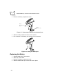
Changing the Battery . . . . . . . . . . . . . . . . . . . . . . . . . . . . . . . . . . . . . . . . . . . . . . . . . . . . . . . . . . . 4-1
Removing the Battery . . . . . . . . . . . . . . . . . . . . . . . . . . . . . . . . . . . . . . . . . . . . . . . . . . . . . . . 4-1
Replacing the Battery . . . . . . . . . . . . . . . . . . . . . . . . . . . . . . . . . . . . . . . . . . . . . . . . . . . . . . . 4-2
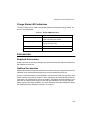
Charge Status LED Indications . . . . . . . . . . . . . . . . . . . . . . . . . . . . . . . . . . . . . . . . . . . . . . . . 4-3
Accessories. . . . . . . . . . . . . . . . . . . . . . . . . . . . . . . . . . . . . . . . . . . . . . . . . . . . . . . . . . . . . . . . . . . 4-3
Required Accessories . . . . . . . . . . . . . . . . . . . . . . . . . . . . . . . . . . . . . . . . . . . . . . . . . . . . . . . 4-3
Optional Accessories . . . . . . . . . . . . . . . . . . . . . . . . . . . . . . . . . . . . . . . . . . . . . . . . . . . . . . . . 4-3
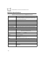
Technical Specifications . . . . . . . . . . . . . . . . . . . . . . . . . . . . . . . . . . . . . . . . . . . . . . . . . . . . . . . . . 4-4
iv
Contents
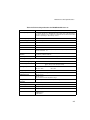
Pin-outs . . . . . . . . . . . . . . . . . . . . . . . . . . . . . . . . . . . . . . . . . . . . . . . . . . . . . . . . . . . . . . . . . . . . .
Cradle . . . . . . . . . . . . . . . . . . . . . . . . . . . . . . . . . . . . . . . . . . . . . . . . . . . . . . . . . . . . . . . . . . .
Scanner . . . . . . . . . . . . . . . . . . . . . . . . . . . . . . . . . . . . . . . . . . . . . . . . . . . . . . . . . . . . . . . . .
Beeper Indications . . . . . . . . . . . . . . . . . . . . . . . . . . . . . . . . . . . . . . . . . . . . . . . . . . . . . . . . . . . . .
4-6
4-6
4-7
4-8
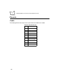
Chapter 5. Parameter Menus
Introduction . . . . . . . . . . . . . . . . . . . . . . . . . . . . . . . . . . . . . . . . . . . . . . . . . . . . . . . . . . . . . . . . . . 5-1
Operational Parameters. . . . . . . . . . . . . . . . . . . . . . . . . . . . . . . . . . . . . . . . . . . . . . . . . . . . . . . . . 5-1
Set Default Parameter . . . . . . . . . . . . . . . . . . . . . . . . . . . . . . . . . . . . . . . . . . . . . . . . . . . . . . . . . . 5-9
Communication Protocol . . . . . . . . . . . . . . . . . . . . . . . . . . . . . . . . . . . . . . . . . . . . . . . . . . . . . . . 5-10
Scan & Transmit Application. . . . . . . . . . . . . . . . . . . . . . . . . . . . . . . . . . . . . . . . . . . . . . . . . 5-10
Batch/Inventory Application . . . . . . . . . . . . . . . . . . . . . . . . . . . . . . . . . . . . . . . . . . . . . . . . . 5-11
Host Type . . . . . . . . . . . . . . . . . . . . . . . . . . . . . . . . . . . . . . . . . . . . . . . . . . . . . . . . . . . . . . . . . . 5-12
RS-232 Host Types . . . . . . . . . . . . . . . . . . . . . . . . . . . . . . . . . . . . . . . . . . . . . . . . . . . . . . . 5-12
Sleep Time. . . . . . . . . . . . . . . . . . . . . . . . . . . . . . . . . . . . . . . . . . . . . . . . . . . . . . . . . . . . . . . . . . 5-15
Date Separator . . . . . . . . . . . . . . . . . . . . . . . . . . . . . . . . . . . . . . . . . . . . . . . . . . . . . . . . . . . . . . 5-16
Hour Type . . . . . . . . . . . . . . . . . . . . . . . . . . . . . . . . . . . . . . . . . . . . . . . . . . . . . . . . . . . . . . . . . . 5-17
Decimal Separator . . . . . . . . . . . . . . . . . . . . . . . . . . . . . . . . . . . . . . . . . . . . . . . . . . . . . . . . . . . . 5-18
Date Format . . . . . . . . . . . . . . . . . . . . . . . . . . . . . . . . . . . . . . . . . . . . . . . . . . . . . . . . . . . . . . . . . 5-19
Key Click . . . . . . . . . . . . . . . . . . . . . . . . . . . . . . . . . . . . . . . . . . . . . . . . . . . . . . . . . . . . . . . . . . . 5-20
Laser On Time . . . . . . . . . . . . . . . . . . . . . . . . . . . . . . . . . . . . . . . . . . . . . . . . . . . . . . . . . . . . . . . 5-21
Scan Stand Options . . . . . . . . . . . . . . . . . . . . . . . . . . . . . . . . . . . . . . . . . . . . . . . . . . . . . . . . . . . 5-22
Time Delay to Low Power Mode. . . . . . . . . . . . . . . . . . . . . . . . . . . . . . . . . . . . . . . . . . . . . . 5-22
Timeout Between Decodes . . . . . . . . . . . . . . . . . . . . . . . . . . . . . . . . . . . . . . . . . . . . . . . . . 5-22
Beeper Options . . . . . . . . . . . . . . . . . . . . . . . . . . . . . . . . . . . . . . . . . . . . . . . . . . . . . . . . . . . . . . 5-25
Beeper Tone . . . . . . . . . . . . . . . . . . . . . . . . . . . . . . . . . . . . . . . . . . . . . . . . . . . . . . . . . . . . . 5-25
Beeper Volume . . . . . . . . . . . . . . . . . . . . . . . . . . . . . . . . . . . . . . . . . . . . . . . . . . . . . . . . . . . 5-26
Power Detect Beep. . . . . . . . . . . . . . . . . . . . . . . . . . . . . . . . . . . . . . . . . . . . . . . . . . . . . . . . 5-27
Beep After Good Decode . . . . . . . . . . . . . . . . . . . . . . . . . . . . . . . . . . . . . . . . . . . . . . . . . . . 5-28
Decode Options . . . . . . . . . . . . . . . . . . . . . . . . . . . . . . . . . . . . . . . . . . . . . . . . . . . . . . . . . . . . . . 5-29
Transmit “No Read” Message. . . . . . . . . . . . . . . . . . . . . . . . . . . . . . . . . . . . . . . . . . . . . . . . 5-29
Enable/Disable UPC-E/UPC-A/UPC-E1 . . . . . . . . . . . . . . . . . . . . . . . . . . . . . . . . . . . . . . . . . . . 5-30
Enable/Disable EAN-8/EAN-13 . . . . . . . . . . . . . . . . . . . . . . . . . . . . . . . . . . . . . . . . . . . . . . . . . . 5-31
Enable/Disable Bookland EAN . . . . . . . . . . . . . . . . . . . . . . . . . . . . . . . . . . . . . . . . . . . . . . . . . . 5-32
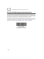
Decode UPC/EAN Supplementals. . . . . . . . . . . . . . . . . . . . . . . . . . . . . . . . . . . . . . . . . . . . . . . . 5-33
Decode UPC/EAN Supplemental Redundancy . . . . . . . . . . . . . . . . . . . . . . . . . . . . . . . . . . . . . . 5-34
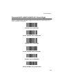
Transmit UPC-A/UPC-E/UPC-E1 Check Digit . . . . . . . . . . . . . . . . . . . . . . . . . . . . . . . . . . . . . . . 5-35
UPC-A Preamble . . . . . . . . . . . . . . . . . . . . . . . . . . . . . . . . . . . . . . . . . . . . . . . . . . . . . . . . . . . . . 5-36
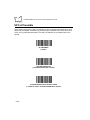
UPC-E Preamble . . . . . . . . . . . . . . . . . . . . . . . . . . . . . . . . . . . . . . . . . . . . . . . . . . . . . . . . . . . . . 5-37
UPC-E1 Preamble . . . . . . . . . . . . . . . . . . . . . . . . . . . . . . . . . . . . . . . . . . . . . . . . . . . . . . . . . . . . 5-38
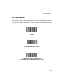
Convert UPC-E to UPC-A . . . . . . . . . . . . . . . . . . . . . . . . . . . . . . . . . . . . . . . . . . . . . . . . . . . . . . 5-39
Convert UPC-E1 to UPC-A . . . . . . . . . . . . . . . . . . . . . . . . . . . . . . . . . . . . . . . . . . . . . . . . . . . . . 5-40
EAN Zero Extend . . . . . . . . . . . . . . . . . . . . . . . . . . . . . . . . . . . . . . . . . . . . . . . . . . . . . . . . . . . . . 5-41
v
P460/P360 Memory Scanners Product Reference Guide
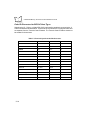
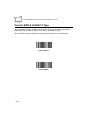
Convert EAN-8 to EAN-13 Type . . . . . . . . . . . . . . . . . . . . . . . . . . . . . . . . . . . . . . . . . . . . . . . . . . 5-42
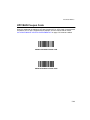
UPC/EAN Coupon Code . . . . . . . . . . . . . . . . . . . . . . . . . . . . . . . . . . . . . . . . . . . . . . . . . . . . . . . . 5-43
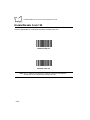
Enable/Disable Code 128 . . . . . . . . . . . . . . . . . . . . . . . . . . . . . . . . . . . . . . . . . . . . . . . . . . . . . . . 5-44
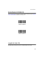
Enable/Disable UCC/EAN-128 . . . . . . . . . . . . . . . . . . . . . . . . . . . . . . . . . . . . . . . . . . . . . . . . . . . 5-45
Lengths for Code 128 . . . . . . . . . . . . . . . . . . . . . . . . . . . . . . . . . . . . . . . . . . . . . . . . . . . . . . . . . . 5-45
Enable/Disable ISBT 128 (2D Scanner only) . . . . . . . . . . . . . . . . . . . . . . . . . . . . . . . . . . . . . . . . 5-46
Enable/Disable Code 39 . . . . . . . . . . . . . . . . . . . . . . . . . . . . . . . . . . . . . . . . . . . . . . . . . . . . . . . . 5-47
Enable/Disable Trioptic Code 39. . . . . . . . . . . . . . . . . . . . . . . . . . . . . . . . . . . . . . . . . . . . . . . . . . 5-48
Set Lengths for Code 39 . . . . . . . . . . . . . . . . . . . . . . . . . . . . . . . . . . . . . . . . . . . . . . . . . . . . . . . . 5-49
Code 39 Check Digit Verification . . . . . . . . . . . . . . . . . . . . . . . . . . . . . . . . . . . . . . . . . . . . . . . . . 5-51
Transmit Code 39 Check Digit . . . . . . . . . . . . . . . . . . . . . . . . . . . . . . . . . . . . . . . . . . . . . . . . . . . 5-52
Enable/Disable Code 39 Full ASCII . . . . . . . . . . . . . . . . . . . . . . . . . . . . . . . . . . . . . . . . . . . . . . . 5-53
Convert Code 39 to Code 32 . . . . . . . . . . . . . . . . . . . . . . . . . . . . . . . . . . . . . . . . . . . . . . . . . . . . 5-54
Code 32 Prefix . . . . . . . . . . . . . . . . . . . . . . . . . . . . . . . . . . . . . . . . . . . . . . . . . . . . . . . . . . . . . . . 5-55
Enable/Disable Code 93 . . . . . . . . . . . . . . . . . . . . . . . . . . . . . . . . . . . . . . . . . . . . . . . . . . . . . . . . 5-56
Set Lengths for Code 93 . . . . . . . . . . . . . . . . . . . . . . . . . . . . . . . . . . . . . . . . . . . . . . . . . . . . . . . . 5-57
Enable/Disable Interleaved 2 of 5 . . . . . . . . . . . . . . . . . . . . . . . . . . . . . . . . . . . . . . . . . . . . . . . . . 5-59
Set Lengths for Interleaved 2 of 5. . . . . . . . . . . . . . . . . . . . . . . . . . . . . . . . . . . . . . . . . . . . . . . . . 5-60
I 2 of 5 Check Digit Verification . . . . . . . . . . . . . . . . . . . . . . . . . . . . . . . . . . . . . . . . . . . . . . . . . . . 5-62
Transmit I 2 of 5 Check Digit. . . . . . . . . . . . . . . . . . . . . . . . . . . . . . . . . . . . . . . . . . . . . . . . . . . . . 5-63
Convert I 2 of 5 to EAN-13 . . . . . . . . . . . . . . . . . . . . . . . . . . . . . . . . . . . . . . . . . . . . . . . . . . . . . . 5-64
Enable/Disable Discrete 2 of 5 . . . . . . . . . . . . . . . . . . . . . . . . . . . . . . . . . . . . . . . . . . . . . . . . . . . 5-65
Set Lengths for Discrete 2 of 5 . . . . . . . . . . . . . . . . . . . . . . . . . . . . . . . . . . . . . . . . . . . . . . . . . . . 5-66
Enable/Disable Codabar . . . . . . . . . . . . . . . . . . . . . . . . . . . . . . . . . . . . . . . . . . . . . . . . . . . . . . . . 5-68
Set Lengths for Codabar . . . . . . . . . . . . . . . . . . . . . . . . . . . . . . . . . . . . . . . . . . . . . . . . . . . . . . . . 5-69
CLSI Editing . . . . . . . . . . . . . . . . . . . . . . . . . . . . . . . . . . . . . . . . . . . . . . . . . . . . . . . . . . . . . . . . . 5-71
NOTIS Editing . . . . . . . . . . . . . . . . . . . . . . . . . . . . . . . . . . . . . . . . . . . . . . . . . . . . . . . . . . . . . . . . 5-72
Enable/Disable MSI Plessey . . . . . . . . . . . . . . . . . . . . . . . . . . . . . . . . . . . . . . . . . . . . . . . . . . . . . 5-73
Set Lengths for MSI Plessey. . . . . . . . . . . . . . . . . . . . . . . . . . . . . . . . . . . . . . . . . . . . . . . . . . . . . 5-74
MSI Plessey Check Digits . . . . . . . . . . . . . . . . . . . . . . . . . . . . . . . . . . . . . . . . . . . . . . . . . . . . . . . 5-76
Transmit MSI Plessey Check Digit . . . . . . . . . . . . . . . . . . . . . . . . . . . . . . . . . . . . . . . . . . . . . . . . 5-77
MSI Plessey Check Digit Algorithm. . . . . . . . . . . . . . . . . . . . . . . . . . . . . . . . . . . . . . . . . . . . . . . . 5-78
Enable/Disable PDF417 . . . . . . . . . . . . . . . . . . . . . . . . . . . . . . . . . . . . . . . . . . . . . . . . . . . . . . . . 5-79
PDF417 Scanning Mode . . . . . . . . . . . . . . . . . . . . . . . . . . . . . . . . . . . . . . . . . . . . . . . . . . . . . . . . 5-80
Programmable Raster Height And Raster Expansion Speed . . . . . . . . . . . . . . . . . . . . . . . . 5-80
Aiming Mode . . . . . . . . . . . . . . . . . . . . . . . . . . . . . . . . . . . . . . . . . . . . . . . . . . . . . . . . . . . . . 5-83
Enable/Disable MicroPDF. . . . . . . . . . . . . . . . . . . . . . . . . . . . . . . . . . . . . . . . . . . . . . . . . . . . . . . 5-84
Code 128 Emulation . . . . . . . . . . . . . . . . . . . . . . . . . . . . . . . . . . . . . . . . . . . . . . . . . . . . . . . . . . . 5-85
UCC/EAN-128 Emulation . . . . . . . . . . . . . . . . . . . . . . . . . . . . . . . . . . . . . . . . . . . . . . . . . . . . . . . 5-86
Macro PDF Features. . . . . . . . . . . . . . . . . . . . . . . . . . . . . . . . . . . . . . . . . . . . . . . . . . . . . . . . . . . 5-87
Macro PDF Transmit / Decode Mode Symbols . . . . . . . . . . . . . . . . . . . . . . . . . . . . . . . . . . . 5-88
Macro PDF Transmit / Decode Mode Symbols (Continued) . . . . . . . . . . . . . . . . . . . . . . . . . 5-89
Transmit Symbols in Codeword Format. . . . . . . . . . . . . . . . . . . . . . . . . . . . . . . . . . . . . . . . . 5-90
Transmit Unknown Codewords . . . . . . . . . . . . . . . . . . . . . . . . . . . . . . . . . . . . . . . . . . . . . . . 5-91
vi
Contents
Escape Characters . . . . . . . . . . . . . . . . . . . . . . . . . . . . . . . . . . . . . . . . . . . . . . . . . . . . . . . . 5-92
Delete Character Set ECIs . . . . . . . . . . . . . . . . . . . . . . . . . . . . . . . . . . . . . . . . . . . . . . . . . . 5-93
ECI Decoder . . . . . . . . . . . . . . . . . . . . . . . . . . . . . . . . . . . . . . . . . . . . . . . . . . . . . . . . . . . . . 5-94
Transmit Macro PDF User-Selected Fields . . . . . . . . . . . . . . . . . . . . . . . . . . . . . . . . . . . . . . . . . 5-95
Transmit File Name . . . . . . . . . . . . . . . . . . . . . . . . . . . . . . . . . . . . . . . . . . . . . . . . . . . . . . . 5-95
Transmit Block Count . . . . . . . . . . . . . . . . . . . . . . . . . . . . . . . . . . . . . . . . . . . . . . . . . . . . . . 5-96
Transmit Time Stamp . . . . . . . . . . . . . . . . . . . . . . . . . . . . . . . . . . . . . . . . . . . . . . . . . . . . . . 5-96
Transmit Sender . . . . . . . . . . . . . . . . . . . . . . . . . . . . . . . . . . . . . . . . . . . . . . . . . . . . . . . . . . 5-97
Transmit Addressee . . . . . . . . . . . . . . . . . . . . . . . . . . . . . . . . . . . . . . . . . . . . . . . . . . . . . . . 5-97
Transmit Checksum . . . . . . . . . . . . . . . . . . . . . . . . . . . . . . . . . . . . . . . . . . . . . . . . . . . . . . . 5-98
Transmit File Size . . . . . . . . . . . . . . . . . . . . . . . . . . . . . . . . . . . . . . . . . . . . . . . . . . . . . . . . . 5-98
Transmit Macro PDF Control Header . . . . . . . . . . . . . . . . . . . . . . . . . . . . . . . . . . . . . . . . . . 5-99
Last Blocker Marker . . . . . . . . . . . . . . . . . . . . . . . . . . . . . . . . . . . . . . . . . . . . . . . . . . . . . . . 5-99
Flush Macro Buffer . . . . . . . . . . . . . . . . . . . . . . . . . . . . . . . . . . . . . . . . . . . . . . . . . . . . . . . 5-100
Abort Macro PDF Entry. . . . . . . . . . . . . . . . . . . . . . . . . . . . . . . . . . . . . . . . . . . . . . . . . . . . 5-100
Security Options . . . . . . . . . . . . . . . . . . . . . . . . . . . . . . . . . . . . . . . . . . . . . . . . . . . . . . . . . . . . 5-101
Linear Code Type Security Levels . . . . . . . . . . . . . . . . . . . . . . . . . . . . . . . . . . . . . . . . . . . 5-101
Linear Code Type Security Level (Continued) . . . . . . . . . . . . . . . . . . . . . . . . . . . . . . . . . . 5-102
Bi-directional Redundancy . . . . . . . . . . . . . . . . . . . . . . . . . . . . . . . . . . . . . . . . . . . . . . . . . 5-103
UPC/EAN Security Level . . . . . . . . . . . . . . . . . . . . . . . . . . . . . . . . . . . . . . . . . . . . . . . . . . 5-104
UPC/EAN Security Level (Continued) . . . . . . . . . . . . . . . . . . . . . . . . . . . . . . . . . . . . . . . . 5-105
RS-232C Parameters. . . . . . . . . . . . . . . . . . . . . . . . . . . . . . . . . . . . . . . . . . . . . . . . . . . . . . . . . 5-106
Baud Rate. . . . . . . . . . . . . . . . . . . . . . . . . . . . . . . . . . . . . . . . . . . . . . . . . . . . . . . . . . . . . . 5-106
Baud Rate (Continued) . . . . . . . . . . . . . . . . . . . . . . . . . . . . . . . . . . . . . . . . . . . . . . . . . . . . 5-107
Parity . . . . . . . . . . . . . . . . . . . . . . . . . . . . . . . . . . . . . . . . . . . . . . . . . . . . . . . . . . . . . . . . . 5-108
Check Receive Errors. . . . . . . . . . . . . . . . . . . . . . . . . . . . . . . . . . . . . . . . . . . . . . . . . . . . . 5-109
Hardware Handshaking . . . . . . . . . . . . . . . . . . . . . . . . . . . . . . . . . . . . . . . . . . . . . . . . . . . 5-110
Hardware Handshaking (Continued) . . . . . . . . . . . . . . . . . . . . . . . . . . . . . . . . . . . . . . . . . 5-111
Hardware Handshaking (Continued) . . . . . . . . . . . . . . . . . . . . . . . . . . . . . . . . . . . . . . . . . 5-111
Software Handshaking . . . . . . . . . . . . . . . . . . . . . . . . . . . . . . . . . . . . . . . . . . . . . . . . . . . . 5-112
Software Handshaking (Continued) . . . . . . . . . . . . . . . . . . . . . . . . . . . . . . . . . . . . . . . . . . 5-113
Software Handshaking (Continued) . . . . . . . . . . . . . . . . . . . . . . . . . . . . . . . . . . . . . . . . . . 5-114
Host Serial Response Time-out . . . . . . . . . . . . . . . . . . . . . . . . . . . . . . . . . . . . . . . . . . . . . 5-114
RTS Line State . . . . . . . . . . . . . . . . . . . . . . . . . . . . . . . . . . . . . . . . . . . . . . . . . . . . . . . . . . 5-115
Stop Bit Select . . . . . . . . . . . . . . . . . . . . . . . . . . . . . . . . . . . . . . . . . . . . . . . . . . . . . . . . . . 5-116
ASCII Format . . . . . . . . . . . . . . . . . . . . . . . . . . . . . . . . . . . . . . . . . . . . . . . . . . . . . . . . . . . 5-116
Beep on <BEL> . . . . . . . . . . . . . . . . . . . . . . . . . . . . . . . . . . . . . . . . . . . . . . . . . . . . . . . . . 5-117
Intercharacter Delay . . . . . . . . . . . . . . . . . . . . . . . . . . . . . . . . . . . . . . . . . . . . . . . . . . . . . . 5-117
MCL-Net Parameters. . . . . . . . . . . . . . . . . . . . . . . . . . . . . . . . . . . . . . . . . . . . . . . . . . . . . . . . . 5-118
MCL-Net Baud Rate . . . . . . . . . . . . . . . . . . . . . . . . . . . . . . . . . . . . . . . . . . . . . . . . . . . . . . 5-118
MCL-Net Baud Rate (Continued) . . . . . . . . . . . . . . . . . . . . . . . . . . . . . . . . . . . . . . . . . . . . 5-119
MCL-Net Hex Addressing Mode. . . . . . . . . . . . . . . . . . . . . . . . . . . . . . . . . . . . . . . . . . . . . 5-120
Scanner Address . . . . . . . . . . . . . . . . . . . . . . . . . . . . . . . . . . . . . . . . . . . . . . . . . . . . . . . . 5-120
MCL-Net Transmit Retries . . . . . . . . . . . . . . . . . . . . . . . . . . . . . . . . . . . . . . . . . . . . . . . . . 5-121
vii
P460/P360 Memory Scanners Product Reference Guide
MCL-Net Frame Timeout . . . . . . . . . . . . . . . . . . . . . . . . . . . . . . . . . . . . . . . . . . . . . . . . . . . 5-121
Numeric Bar Codes. . . . . . . . . . . . . . . . . . . . . . . . . . . . . . . . . . . . . . . . . . . . . . . . . . . . . . . . . . . 5-122
Cancel . . . . . . . . . . . . . . . . . . . . . . . . . . . . . . . . . . . . . . . . . . . . . . . . . . . . . . . . . . . . . . . . . 5-124
Appendix A. Bar Code Information
UCC/EAN-128. . . . . . . . . . . . . . . . . . . . . . . . . . . . . . . . . . . . . . . . . . . . . . . . . . . . . . . . . . . . . . . . .A-1
AIM Code Identifiers . . . . . . . . . . . . . . . . . . . . . . . . . . . . . . . . . . . . . . . . . . . . . . . . . . . . . . . . . . . . A-3
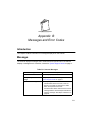
Appendix B. Messages and Error Codes
Introduction . . . . . . . . . . . . . . . . . . . . . . . . . . . . . . . . . . . . . . . . . . . . . . . . . . . . . . . . . . . . . . . . . . .B-1
Messages . . . . . . . . . . . . . . . . . . . . . . . . . . . . . . . . . . . . . . . . . . . . . . . . . . . . . . . . . . . . . . . . . . . .B-1
Index
Feedback
viii
About This Manual
Introduction
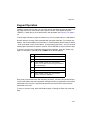
The P460/P360 Memory Scanner Product Reference Guide provides general instructions
for setup, operation, troubleshooting, maintenance, and programming the Phaser Batch
scanners.
Chapter Descriptions
!
Chapter 1, The Phaser Series Scanner, describes the Phaser, the battery, and the
cradle.
!
Chapter 2, Set Up, explains how to set up the Phaser scanner.
!
Chapter 3, Operation, explains how to operate the Phaser scanner.
!
Chapter 4, Maintenance And Specifications, talks about the maintenance and the
specifications of the Phaser scanner and the cradle.
!
Chapter 5, Parameter Menus, has all the optional parameter bar codes for
personalizing your Phaser.
!
Appendix A, Bar Code Information, has information about bar codes.
!
Appendix B, Messages and Error Codes, describes the messages and error codes
displayed by the scanner.
Notational Conventions
The following conventions are used in this document:
!
Bullets (•) indicate:
"
action items
ix
P460/P360 Memory Scanners Product Reference Guide
!
"
lists of alternatives
"
lists of required steps that are not necessarily sequential
Sequential lists (e.g., those that describe step-by-step procedures) appear as
numbered lists.
Related Publications
!
P460/P360 Memory Scanners Quick Reference Guide, p/n 70-33628-xx
!
PL 460 Cradle Quick Reference Guide, p/n 70-33657-xx
!
MCL Designer for Phaser Series User’s Guide, p/n 70-37689-xx
Service Information
If you have a problem with your equipment, contact the Symbol Support Center. Before
calling, have the model number, serial number, and several of your bar code symbols at
hand.
Call the Support Center from a phone near the scanning equipment so that the service
person can try to talk you through your problem. If the equipment is found to be working
properly and the problem is symbol readability, the Support Center will request samples of
your bar codes for analysis at our plant.
If your problem cannot be solved over the phone, you may need to return your equipment
for servicing. If that is necessary, you will be given specific directions.
Note: Symbol Technologies is not responsible for any damages incurred
during shipment if the approved shipping container is not used.
Shipping the units improperly can possibly void the warranty. If the
original shipping container was not kept, contact Symbol to have
another sent to you.
x
About This Manual
Symbol Support Center
For service information, warranty information or technical assistance contact or call the
Symbol Support Center in:
United States
Symbol Technologies, Inc.
One Symbol Plaza
Holtsville, New York 11742-1300
1-800-653-5350
Canada
Symbol Technologies Canada, Inc.
2540 Matheson Boulevard East
Mississauga, Ontario, Canada L4W 4Z2
905-629-7226
United Kingdom
Symbol Technologies
Symbol Place
Winnersh Triangle, Berkshire RG41 5TP
United Kingdom
0800 328 2424 (Inside UK)
+44 208 945 7529 (Outside UK)
Asia/Pacific
Symbol Technologies Asia, Inc.
230 Victoria Street #04-05
Bugis Junction Office Tower
Singapore 188024
337-6588 (Inside Singapore)
+65-337-6588 (Outside Singapore)
Australia
Symbol Technologies Pty. Ltd.
432 St. Kilda Road
Melbourne, Victoria 3004
1-800-672-906 (Inside Australia)
+61-3-9866-6044 (Outside Australia)
Austria
Symbol Technologies Austria GmbH
Prinz-Eugen Strasse 70
Suite 3
2.Haus, 5.Stock
1040 Vienna, Austria
1-505-5794 (Inside Austria)
+43-1-505-5794 (Outside Austria)
Denmark
Symbol Technologies AS
Gydevang 2,
DK-3450 Allerod, Denmark
7020-1718 (Inside Denmark)
+45-7020-1718 (Outside Denmark)
Europe/Mid-East Distributor Operations
Contact your local distributor or call
+44 208 945 7360
xi
P460/P360 Memory Scanners Product Reference Guide
Finland
Oy Symbol Technologies
Kaupintie 8 A 6
FIN-00440 Helsinki, Finland
9 5407 580 (Inside Finland)
+358 9 5407 580 (Outside Finland)
France
Symbol Technologies France
Centre d'Affaire d'Antony
3 Rue de la Renaissance
92184 Antony Cedex, France
01-40-96-52-21 (Inside France)
+33-1-40-96-52-50 (Outside France)
Germany
Symbol Technologies GmbH
Waldstrasse 68
D-63128 Dietzenbach, Germany
6074-49020 (Inside Germany)
+49-6074-49020 (Outside Germany)
Italy
Symbol Technologies Italia S.R.L.
Via Cristoforo Columbo, 49
20090 Trezzano S/N Navigilo
Milano, Italy
2-484441 (Inside Italy)
+39-02-484441 (Outside Italy)
Latin America Sales Support
7900 Glades Road
Suite 340
Boca Raton, Florida 33434 USA
1-800-347-0178 (Inside United States)
+1-561-483-1275 (Outside United States)
Mexico
Symbol Technologies Mexico Ltd.
Torre Picasso
Boulevard Manuel Avila Camacho No 88
Lomas de Chapultepec CP 11000
Mexico City, DF, Mexico
5-520-1835 (Inside Mexico)
+52-5-520-1835 (Outside Mexico)
Netherlands
Symbol Technologies
Kerkplein 2, 7051 CX
Postbus 24 7050 AA
Varsseveld, Netherlands
315-271700 (Inside Netherlands)
+31-315-271700 (Outside Netherlands)
Norway
Symbol Technologies
Trollasveien 36
Postboks 72
1414 Trollasen, Norway
66810600 (Inside Norway)
+47-66810600 (Outside Norway)
xii
About This Manual
South Africa
Symbol Technologies Africa Inc.
Block B2
Rutherford Estate
1 Scott Street
Waverly 2090 Johannesburg
Republic of South Africa
11-4405668 (Inside South Africa)
+27-11-4405668 (Outside South Africa)
Spain
Symbol Technologies S.A.
Edificioi la Piovera Azul
C. Peonias, No. 2 - Sexta Planta
28042 Madrid, Spain
9-1-320-39-09 (Inside Spain)
+34-9-1-320-39-09 (Outside Spain)
Sweden
Symbol Technologies AB
Albygatan 109D
Solna
Sweden
84452900 (Inside Sweden)
+46 84452900 (Outside Sweden)
If you purchased your Symbol product from a Symbol Business Partner, contact that
Business Partner for service.
Warranty
Symbol Technologies, Inc. (“Symbol”) manufactures its hardware products in accordance with
industry-standard practices. Symbol warrants that for a period of twelve (12) months from date of
shipment, products will be free from defects in materials and workmanship.
This warranty is provided to the original owner only and is not transferable to any third party. It shall
not apply to any product (i) which has been repaired or altered unless done or approved by Symbol,
(ii) which has not been maintained in accordance with any operating or handling instructions supplied
by Symbol, (iii) which has been subjected to unusual physical or electrical stress, misuse, abuse,
power shortage, negligence or accident or (iv) which has been used other than in accordance with
the product operating and handling instructions. Preventive maintenance is the responsibility of
customer and is not covered under this warranty.
Wear items and accessories having a Symbol serial number, will carry a 90-day limited warranty. Nonserialized items will carry a 30-day limited warranty.
xiii
P460/P360 Memory Scanners Product Reference Guide
Warranty Coverage and Procedure
During the warranty period, Symbol will repair or replace defective products returned to Symbol’s
manufacturing plant in the US. For warranty service in North America, call the Symbol Support Center
at 1-800-653-5350. International customers should contact the local Symbol office or support center.
If warranty service is required, Symbol will issue a Return Material Authorization Number. Products
must be shipped in the original or comparable packaging, shipping and insurance charges prepaid.
Symbol will ship the repaired or replacement product freight and insurance prepaid in North America.
Shipments from the US or other locations will be made F.O.B. Symbol’s manufacturing plant.
Symbol will use new or refurbished parts at its discretion and will own all parts removed from repaired
products. Customer will pay for the replacement product in case it does not return the replaced
product to Symbol within 3 days of receipt of the replacement product. The process for return and
customer’s charges will be in accordance with Symbol’s Exchange Policy in effect at the time of the
exchange.
Customer accepts full responsibility for its software and data including the appropriate backup
thereof.
Repair or replacement of a product during warranty will not extend the original warranty term.
Symbol’s Customer Service organization offers an array of service plans, such as on-site, depot, or
phone support, that can be implemented to meet customer’s special operational requirements and
are available at a substantial discount during warranty period.
General
Except for the warranties stated above, Symbol disclaims all warranties, express or implied, on
products furnished hereunder, including without limitation implied warranties of merchantability and
fitness for a particular purpose. The stated express warranties are in lieu of all obligations or liabilities
on part of Symbol for damages, including without limitation, special, indirect, or consequential
damages arising out of or in connection with the use or performance of the product.
Seller’s liability for damages to buyer or others resulting from the use of any product, shall in no way
exceed the purchase price of said product, except in instances of injury to persons or property.
Some states (or jurisdictions) do not allow the exclusion or limitation of incidental or consequential
damages, so the proceeding exclusion or limitation may not apply to you.
xiv
Chapter 1
The Phaser Series Scanner
Introduction
The P460/P360 Memory Scanners bring new flexibility and economy to data capture and
data management in both retail and industrial operations. In addition to an integrated bar
code scanner, the Phaser has an on-board keyboard and display. They can operate in both
corded and battery-powered cordless modes. There are many versions available:
!
1D P 460: the batch retail version
!
1D P 360: the batch industrial version
!
2D P 460: the batch retail version
!
2D P 360: the batch industrial version
Unless otherwise noted, the term Phaser refers to all versions of the scanner.
Rechargeable Battery
In the handle of the scanner, there is a rechargeable lithium-ion battery. This provides all
power to the scanner during cordless operation. It provides 12 hours of use in a typical
application.
When fully depleted, the battery can be recharged to full charge in about 3-1/2 hours.
1-1
P460/P360 Memory Scanners Product Reference Guide
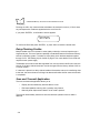
The Cradle
The PL 460 and PL 360 Cradles act as a:
!
stand
!
communication interface with the host
!
battery charger for the Phaser Batch Scanner.
Note: The cradle is not required for certain applications.
The scanner battery also charges when a power supply cable is
attached.
The cradle can sit on a desktop or be wall-mounted, whichever is more convenient. It
receives data from the scanner via connectors in the bottom of the scanner and the top of
the cradle. It then transmits that data to the host device through an attached cable. It also
acts as a holder for the scanner.
The cradle also provides power for charging the scanner’s battery (in the scanner). The
cradle has a charge status indicator light that shows the status of the battery charging
(Refer to Table 4-1 on page 4-3).
Charge Status
Indicator Light
Figure 1-1. Scanner and Cradle
1-2
The Phaser Series Scanner
There are two versions of the Cradle:
!
PL 460 Cradle: batch retail version
!
PL 360 Cradle: batch industrial version.
Unless otherwise noted, the term Cradle refers to both versions of the cradle.
1-3
P460/P360 Memory Scanners Product Reference Guide
1-4
Chapter 2
Set Up
Introduction
This chapter covers the procedures for setting up the Phaser and its accessories.
Unpacking
Remove the scanner from its packing and inspect it for damage. If the scanner was
damaged in transit, call one of the telephone numbers listed in the section Symbol Support
Center on page xi. KEEP THE PACKING. It is the approved shipping container and should
be used if you ever need to return your equipment for servicing.
Cables
Installing the Cable on the Scanner
1. Power down all devices that will be connected to the scanner.
2-1
P460/P360 Memory Scanners Product Reference Guide
2. Plug the modular connector on the cable into the receptacle in the bottom of the
Phaser handle.
The twist-lock
can be slipped
down the
cable to
facilitate
connecting.
Figure 2-1. Connecting the Cable to the Phaser
3. Turn the cable twist-lock 1/8 turn clockwise to seat it.
locked position
Figure 2-2. Locking the Cable to the Phaser
4. Gently pull the cable to make certain it is properly seated.
2-2
Set Up
Disconnecting Cables
To disconnect the scanner cable:
1. Power down all the devices connected to the scanner.
2. Remove the cable by twisting the twist-lock 1/8 turn counter-clockwise and pulling
the cable out.
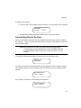
Setting Up the Cradle
On the bottom of the cradle are three ports. COM1 connects to the host computer, COM2
is used for daisy-chaining multiple base stations together, and the Power port supplies
power to the cradle.
COM1
COM2
Power port
Figure 2-1. Ports on the Cradle
1. Connect an appropriate power supply to the Power port on the cradle. The indicator
light on the cradle blinks, signifying successful power-up.
Figure 2-2. Power Supply Port
2. Insert the cable from the host computer into COM1 and the cable to the other base
stations, if any, into COM2. Refer to Connecting to a Host on page 25.
2-3
P460/P360 Memory Scanners Product Reference Guide
Scanner Power Options
Two power options are available:
!
Battery
!
Power Supply (“Charging”) Cable
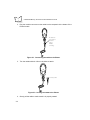
Charging the Battery
Before its first use, the Phaser battery must be charged.
Using the Cradle
1. Connect the power supply to the power input jack on the cradle.
2. Connect the power supply to a receptacle supplying AC power of the proper
voltage level.
3. Insert the scanner into the cradle so that the nose of the scanner and tip of the
handle seat into the receptacles. The scanner displays “UNIT CRADLED” when
properly inserted in the cradle.
Figure 2-3. Placing the Scanner into the Cradle
4. Check the charge status indicator light. For additional information on charging, see
Table 4-1 on page 4-3 .
5. The battery charges automatically. A full charge of a depleted battery takes
approximately 3-1/2 hours.
The cradle recharges batteries in the scanner only when the scanner is in the cradle. A
scanner with a depleted battery starts charging immediately upon insertion into the cradle,
2-4
Set Up
whereas a scanner with a partially charged battery begins charging after approximately 15
minutes. Note that the scanner can be removed from the cradle at any time.
Using the Cable
1. Connect the cable to the scanner.
2. Connect the power supply to the power jack on the cable.
3. Connect the power supply to a receptacle supplying AC power of the proper
voltage level.
4. The battery charges automatically. A full charge of a depleted battery takes
approximately 3-1/2 hours.
Battery Charge
When the battery’s charge is almost depleted, the scanner emits 4 high tone beeps, when
the trigger is pulled, indicating that it must be recharged.
Connecting to a Host
With some host types, the Phaser is unable to answer host terminal polls if the appropriate
host type is not selected. This may result in an error message generated by the host. To
correct this situation, select the proper parameter set and initialize the host terminal. See
Chapter 5, Parameter Menus for more information.
There are two basic host communications options available.
!
When using as a batch device running on a battery, you can transmit stored data
to a host either through an RS-232 or a Synapse cable connected directly to the
scanner, or through the cradle, as described in Setting Up the Cradle on page 23.
!
When using as a corded device, power and host communications takes place via
RS-232 or Synapse cables.
RS-232 Power Supply Operation
1. Make sure all host devices are powered down.
2. Plug the connector at the end of the scanner’s or cradle’s cable into an appropriate
RS-232 receiving port on the host device.
2-5
P460/P360 Memory Scanners Product Reference Guide
3. For the scanner cable, plug the power supply cable into the power supply port on
the housing of the host connector. For the cradle cable, plug the power supply
cable into the Power port on the bottom of the cradle.
4. Connect the power supply into an AC receptacle.
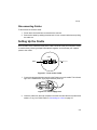
Using A Synapse Cable with the Cradle
1. Connect the Synapse Adapter cable to COM1 in the cradle.
2. Connect the Adapter cable to the Synapse Interface cable.
3. The Synapse Adapter cable has a flying power lead. Connect this lead to the
receptacle in the Synapse Interface cable, as shown below. See the Synapse
guide for details.
To Host
Synapse
Adapter Cable
Flying Power Lead
To Cradle
Figure 2-4. Synapse and Adapter Cable
4. Connect the Synapse Interface cable to the host.
5. Connect an appropriate power supply to the power receptacle on the cradle. The
indicator light on the cradle blinks, signifying successful power-up.
Using a Synapse Cable with the Scanner
1. Connect the Synapse Adapter cable into the bottom of the scanner.
2. Connect the Synapse Adapter cable to the Synapse Interface cable .
3. Connect the Synapse Adapter cable’s flying power lead to the receptacle in the
Synapse Interface cable (refer to Figure 2-4).
2-6
Set Up
4. Plug the Synapse Interface cable into the host device.
5. Connect an appropriate power supply to the power receptacle in the Synapse
Interface cable.
Wand Emulation, OCIA, OCR, Keyboard Wedges
See the instructions packed with the appropriate Synapse cable. An adapter cable is
required. See Figure 2-4 on page 2-6.
2-7
P460/P360 Memory Scanners Product Reference Guide
2-8
Chapter 3
Operation
Introduction
This chapter covers how to use the Phaser scanner.
Default Applications
The Phaser is shipped from the factory with two ready to use default applications:
•
Scan and Transmit
•
Batch / Inventory
These applications allow users to scan and view data, enter quantities, manually enter
data, and much more.
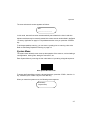
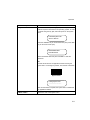
When the unit is initially powered up (e.g., when a new battery is inserted), it displays the
system start-up banner. Alternatively, the scanner can be reset manually by pressing the
<FUNC> key, then the <*> key. When the scanner is powered up or reset, the system
banner appears as follows:
Symbol Technologies
Phaser Memory Scnr
3-1
P460/P360 Memory Scanners Product Reference Guide
Initial Powerup
After a few seconds, the System Banner is replaced by the system initialization screen.
Symbol Technologies
Initializing...
After initialization, the scanner enters either the Scan & Transmit mode, or the Batch/
Inventory mode, depending on whether a communications cable is present or not. The
default communication protocols are:
•
RS232/Synapse for Scan & Transmit
•
MCL NET for Batch/Inventory
If a Synapse cable is attached, the scanner automatically overrides the default settings.
Batch / Inventory Application
The batch/inventory application is a scan-and-store program and allows you to:
•
Display and store (Batch) data for transmission later
•
Eliminate repetitive scanning with a quantity entry feature
•
Manually enter alphanumeric data if no bar code is present
•
Review and delete stored records
•
Transmit stored (batch) data to a host.
The scanner automatically switches to batch/inventory mode operation when the scanner
is removed from its cradle or its cable is disconnected.
The following screen appears:
SCAN:___________________
__________________
Scanned bar code data is automatically displayed and stored for review and transmission
to a host at a later date.
If the scanner powers down, pull the trigger or press the <ENTER> key to wake it up.
3-2
Operation
Numeric Data Entry
This inventory application also allows you to manually enter data if no bar code is present.
After keying in data, press the <ENTER> key. During data entry, the <BK> key corrects
keying errors digit by digit, and the <FUNC> + <BK> combination clears the screen so you
can start over. If your entry exceeds 34 characters, the characters will scroll off the visible
portion of the screen, but are retained for storage.
Alpha Data Entry
To enter alpha characters, press the <Mode> key once to put the scanner in Alpha Mode.
Numeric buttons 1 through 9 are associated with the alpha characters. For example, the
letters a, b and c are located on numeric button 7. Press the button with the letter you desire
- once for the letter a, twice for the letter b, or three times for the letter c. You can continue
entering alpha characters or switch to numerics. Press <ENTER> to save or send the data.
To return to numeric entry mode after entering alpha characters, press the <Mode> key
again. For example, to manually enter 17ABF5, do the following steps:
Data
Action
1
Press numeric button 1.
7
Press numeric button 7.
A
Press <MODE> button once, then numeric
button 7 once. Wait for one second (you will hear a
low pitched beep).
B
Press numeric button 7 twice.
F
Press numeric button 8 three times.
5
Press <MODE> button once, then numeric
button 5 once, then <ENTER>.
For more information, refer to Keypad Operation on page 3-21.
3-3
P460/P360 Memory Scanners Product Reference Guide
Eliminating Repetitive Scanning
To eliminate repetitive scanning of identical items, you can enter a quantity prior to scanning
a bar code. This quantity entry feature can also be used when manually entering bar code
data.
To enter a quantity, press the * key. The following screen appears:
Quantity: _____
Then, key in a quantity followed by the <ENTER> key. Next, the bar code data entry screen
reappears. Scan the item’s bar code. The scanner sends the bar code data to the host the
keyed-in amount of times. For instance, if you type in a quantity of 6 then scan a bar code,
the scanner sends that bar code data to the host six times as if the bar code had been
scanned six times.
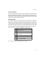
Reviewing and Deleting Stored Records
While running the inventory application, you can review and delete stored data. Press the
<FUNC> key, then the <2> key to enter this mode. The following screen appears:
CODE: xxxx
aaaa/bbbb
Three fields are shown on this screen:
•
xxxx = the data contained within the record (the first 25 characters)
•
aaaa = the record number of the file being viewed.
•
bbbb = the number of total records stored.
Use the up
and down
arrow keys to scroll through the stored data.
Press <ENTER> or the <FUNC> key, then the <BK> key at any time to exit the review
mode.
3-4
Operation
To delete stored records:
1. Press the <BK> key to select a record to delete. The confirmation screen displays:
Delete (data)
Yes <EN>
No <BK>
2. Press Enter to delete the record or <BK> key to cancel the process.
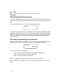
Transmitting Data to the Host
When you are ready to transmit your stored (Batch) data to the host, press the <FUNC>
key, then the <1> key on the key pad, then place the scanner in the cradle or connect the
communication cable.
Note: When attached to a cable, the scanner will automatically begin
running the Scan & Transmit application. The stored (Batch) data will
not be transmitted to the host until the <FUNC> key, then <1> key is
entered.
The scanner indicates the transfer is in progress with the following screen:
Uploading data.
Please wait ...
You have 30 seconds from the time that this screen appears to either insert the scanner
into a cradle or attach a communications cable. If you fail to do so, the following screen
appears:
Upload Failed! Retry?
<EN>=Y <BK>=N
If the upload is successful, the following screen appears:
Success! Erase Data?
<EN>=Y <BK>=N
3-5
P460/P360 Memory Scanners Product Reference Guide
Pressing the <BK> key causes the bar code data to be retained in memory. If this is done,
any subsequent bar codes are appended to the end of the file.
If you press <ENTER>, a confirmation screen appears:
Confirm file erase
<EN>=Y <BK>=N
To confirm the file erase press <ENTER>, or press <BK> to retain the stored data.
Daisy-Chaining Cradles
Multiple cradles can be connected in series (daisy-chained) to communicate through a
single serial port. This out-of-the-box capability is a standard feature of the Phaser memory
scanner’s operating system. To enable it, simply daisy-chain the base stations together
through Com 2. See Setting Up the Cradle on page 2-3 for more details. Each cradle still
requires its own power supply.
To establish which scanner the data originated from, and to prevent a buffer over-write, the
scanner ID of daisy-chained scanners must be changed from the factory default of 001 to
a unique number.
If a scanner is placed in a daisy-chained cradle while another scanner is transferring data
to the host, the second scanner will begin its data transfer after the first scanner’s transfer
is completed.
Scan and Transmit Application
The scan and transmit application allows you to:
•
Display and simultaneously transmit data to a host
•
Eliminate repetitive scanning with a quantity entry feature
•
Manually enter alphanumeric data if no bar code is present.
The scanner automatically switches to scan and transmit operation when a cable is
attached.
3-6
Operation
The scan and transmit screen appears as follows:
SKU:
_____________________
In this mode, scanned bar codes are automatically transmitted to the host in real time.
Alphanumeric data may be manually entered in the same manner as described in the Batch
/ Inventory Application on page 3-2. Keyed data transmits once you press the <ENTER>
key.
To eliminate repetitive scanning, you can enter a quantity prior to scanning a bar code.
Refer to Eliminating Repetitive Scanning on page 3-4.
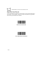
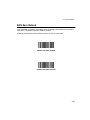
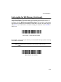
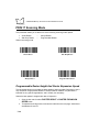
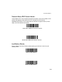
System Menu
The system menu allows the user to set up the operation of the scanner, such as loading a
new application, erasing files, setting the scanner ID, etc.
Enter System Menu by scanning the bar code below or by entering a keypad sequence.
Enter System Menu Bar Code
To access the System Menu using the keypad sequence, press the <FUNC>, then the <*>
key, followed by the <FUNC> key, then the <BK> key.
When you enter the system menu, the following screen appears:
Phaser Setup
0. System Setup
3-7
P460/P360 Memory Scanners Product Reference Guide
Below is the list of available options. Press the Up and Down
arrow keys to scroll
through them. Press <ENTER> to select a menu option. You can also select a menu option
by typing the associated menu option number and then pressing <ENTER>.
0.
1.
2.
3.
4.
5.
9.
System Setup
App. Control
Parameter Control
System Status
Erase File
Version
Return to App
The system menu options are described below.
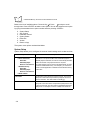
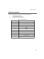
System Setup
System Setup allows you to configure the scanner’s basic settings such as date and time.
Option
Description
0. Set Com Protocol
0. Scan & Transmit
-MCL NET
-RS232/Synapse
-Back to Com Protocol
1. Batch/Inventory
-MCL NET
-RS232/Synapse
-Back to Com Protocol
9. Back to Main
Sets the communication protocol used by the default
applications. The options are MCL-Net or RS232/Synapse. If
RS232/Synapse is selected, the scanner automatically identifies
whether an RS-232 or Synapse interface is required.
The communication protocol can be set independently for Scan
& Transmit and Batch/Inventory. For example, you can set the
Scan & Transmit application to RS232 and the Batch/Inventory
to MCL NET.
1. Set Date
Sets the date of the internal clock of the scanner. The scanner
displays its current date and provides a prompt for the user to
enter the new date. The date format is mm/dd/yyyy.
2. Set Time
Sets the time of the internal clock of the scanner. The scanner
displays its current time value, and provides a prompt for the user
to enter the new time. The time format is HH:MM:SS entered in
military time. For example, to enter 11:25PM, enter 23:25:00.
3-8
Operation
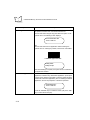
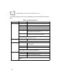
Option
Description
3. Set Contrast
Sets the display contrast. The scanner displays the current
contrast setting. Use the up and down arrow keys to change the
contrast. The default contrast is 4, and the range is from 0 to 7,
with 0 being the lightest and 7 being the darkest. To cancel the
change, press the <FUNC><BK> keys, and to accept the
change, press the <ENTER> key.
4. Set Scanner ID
Sets the scanner ID. The scanner displays its current ID, and the
user may key in a new value between 1 and 254. The default is
001.
9. Back to Main
Returns the user to the system menu.
Note: The scanner contains a backup power source to retain the time and
date information for up to 24 hours after loss of battery power. If
battery power is not restored within 24 hours, time and date
information will be lost.
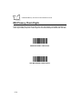
App. Control
App. Control allows you to control your application, specifically, load new system
application files on your scanner, reset your default applications, etc.
You can load a new application/file or system code by either scanning the appropriate bar
code or entering the appropriate keypad value as indicated on the display.
3-9
P460/P360 Memory Scanners Product Reference Guide
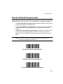
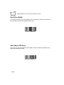
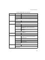
Option
0. Load App / File
Description
Puts the scanner into a mode to receive application downloads,
file updates, and MCL-Link commands from the host.
To enter this mode using the key pad, select this option on the
system menu. The following screen displays:
Com Protocol=MCL NET
<EN>=Y <BK>=N
OR
To enter this mode from an application without entering the
system menu or entering key strokes, scan the bar code below.
Load New Application/File
Loading Status:
Waiting for input
After downloading is complete, the system menu is exited and
the application initiated.
1. Set Default App
Restores the default application described above. The default
application overwrites any downloaded application. (This option
may be used to restore functionality to a scanner which has been
loaded with a defective application.) Prior to resetting the default
application, the user is prompted to confirm this operation:
Reset Default App?
<EN>=Y <BK>=N
Press the <ENTER> key to confirm the choice (Yes) or the <BK>
key to cancel the choice (No).
3-10
Operation
Option
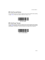
2. System Code
Description
Updates the scanner operating system (Firmware). An RS232
cable is required to download a new operating system. To enter
this mode using the key pad, select this option on the system
menu.
Load New System Code
<EN>=Y <BK>=N
Press the <ENTER> key to confirm the choice (Yes) or the <BK>
key to cancel the choice (No).
Attach RS232 Cable:
Press EN to Start
Attach the RS232 cable and press <ENTER> to start the
download.
OR
To enter this mode from an application without entering the
system menu or entering key strokes, scan the bar code below.
System Code
Loading System Code
...............................
After the download is complete, the system menu is exited and
the application initiates.
9. Back to Main
Returns the user to the system menu.
3-11
P460/P360 Memory Scanners Product Reference Guide
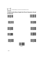
Parameter Control
Parameter Control allows you to control the scanner parameters such as Scan Parameters
and Set Default Params.
Option
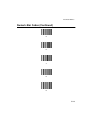
0. Scan Parameters
Description
This option allows you to program your scanner by scanning the
bar codes in Chapter 5, Parameter Menus. Parameters set in your
MCL application can not be changed with this option.
When you see the following screen, you are able to scan the
parameter bar codes:
Scan Parameters
<FUNC> <BK> to quit
After scanning the desired bar codes, press <FUNC> <BK> to exit
this mode.
1. Set Default Param
Restores the default parameters in the scanner. The default
parameters overwrite any scanned parameters. Prior to resetting
the default parameters, you are prompted to confirm your choice.
9. Back to Main
Returns the user to the system menu.
System Status
System Status allows you to perform system checks such as Battery Check.
Option
Description
0. Battery Check
Checks the battery charge level.
Good indicates the battery does not require recharging.
Low/Recharge indicates the scanner requires a recharge.
9. Back to Main
Returns the user to the system menu.
3-12
Operation
Erase File
Erase File allows you to erase your scanner batch data. All batch data files must be
transferred from the scanner to the host before erasing. A screen prompts you to indicate
which file is being erased. The batch/Inventory application data is always saved in file A.
File to Erase?
(A-H)
Enter the file name, (the name is a single letter A-H), and press <ENTER> to erase the file.
Version
This option displays the version of firmware (operating system) run by the scanner, and the
size of the scanner memory, such as 1024K. For example, the firmware version shown on
the display below is NBRVSMAP.
System: NBRVSMAP
MCL: 4.x
Mem: 1024
Return to App
Return to App exits the system setup mode and returns to the application (either the default
application described above, or any downloaded application).
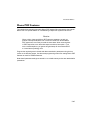
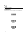
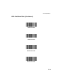
ADF Plus
ADF Plus is an intuitive Windows based utility that allows you to customize your scanner
setup and generate Advanced Data Formatting (ADF) rules. An Advanced Data Formatting
rule gives you the ability to modify the bar code data before sending it to the host. This
enhances capability between bar code data and your host software, allowing you to
program the scanner rather than modifying your host application. The scanner is
programmed by a PC download or by scanning ADF Plus programming bar codes. Scanner
programming is saved in a setup file distributed electronically (Web site, floppy disk, E-mail,
or fax).
3-13
P460/P360 Memory Scanners Product Reference Guide
Note: Advanced data formatting rules created with ADF Plus are for use
with the default applications only and will not work with applications
created with MCL-Designer.
Scanning
The scanner ships with the default application and default parameters that is ready-to-use
right out of the box. If this is not what you need for your application, refer to the MCL
Designer Manual for programming instructions and Chapter 5, Parameter Menus for
scanning and communications parameters. If you need assistance, contact your local
supplier or Symbol Support Center.
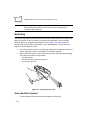
1. If you are using the scanner in corded mode, make sure all cable connections are
secure. Otherwise, make sure the battery is sufficiently charged.
2. Make sure the bar code is in the correct scanning range. Aim and press the trigger.
The scanner has read the symbol when:
•
You hear a beep.
•
The LED above the screen turns green.
•
The red laser turns off.
Figure 3-1. Scanning a Bar Code
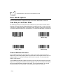
Scan the Entire Symbol
•
3-14
Your scan beam must cross every bar and space on the symbol.
Operation
•
The larger the symbol, the farther away you should hold the scanner.
•
Hold the scanner closer for symbols with bars that are close together.
•
A short, high tone beep indicates a good decode.
Right
Wrong
3-15
P460/P360 Memory Scanners Product Reference Guide
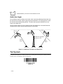
Hold at an Angle
Do not hold the scanner directly over the bar code. Laser light reflecting directly back into
the scanner from the bar code is known as specular reflection. This strong light can “blind”
the scanner and make decoding difficult. The area where specular reflection occurs is
known as a “dead zone.”
You can tilt the scanner up to 65° forward or back and still achieve a successful decode.
Simple practice quickly shows what tolerances to work within.
65°
65°
Shaded area represents
dead zone (±2°)
Scan
Beam
Scan
Beam
Bar Code
Bar Code
Bar Code
Figure 3-2. Maximum Tilt Angles and Dead Zone
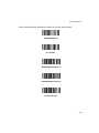
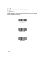
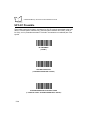
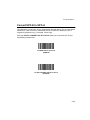
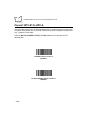
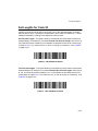
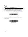
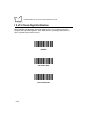
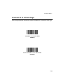
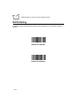
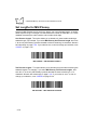
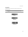
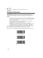
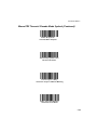
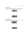
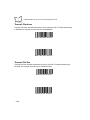
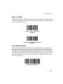
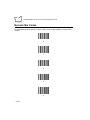
Test Symbols
To ensure your scanner is working properly, try scanning the following bar codes. If you have
trouble, refer to Troubleshooting on page 3-23.
CODE 128
3-16
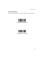
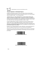
Operation
UPC
Symbol Technologies, Inc.
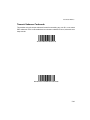
PDF417
3-17
P460/P360 Memory Scanners Product Reference Guide
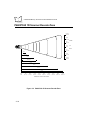
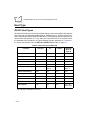
P460/P360 1D Scanner Decode Zone
15.6 in.
39.6 cm
10 in.
25.4 cm
5 in.
12.7 cm
0 in.
0 cm
5 in.
12.7 cm
5 mil
10 in.
25.4 cm
7.5 mil
10 mil
15.6 in.
39.6 cm
100% UPC
15 mil
20 mil
40 mil
55 mil
0 in.
0 cm
5 in.
12.7 cm
10 in.
25.4 cm
15 in.
38.1 cm
20 in.
50.8 cm
25 in.
63.5 cm
30 in.
76.2 cm
35 in.
88.9 cm
40 in.
101.6 cm
Distance From Front Of Scanner
Figure 3-3. P460/P360 1D Scanner Decode Zone
3-18
45 in.
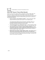
114.3 cm
Width
Of
Field
Operation
P460/P360 2D Scanner Decode Zone
Note: Typical performance at 68˚F (20˚C)
on high quality symbols.
Top of
scanner
1.25
6.6 mil PDF
6.0
10 mil PDF
3.0
15 mil PDF
5.0
In.
cm
0
0
2
5.0
4
10.1
9.5
6
8
15.2 20.3
In.
cm
6
15.2
4
10.1
2
5.0
0
0
2
5.0
4
10.1
6
15.2
W
i
d
t
h
o
f
F
i
e
l
d
15.0
10
12
14
16
25.4 30.5 35.6 40.6
Depth of Field
Figure 3-4. P460/P360 2D Scanner - 2D Bar Code Decode Zone
3-19
P460/P360 Memory Scanners Product Reference Guide
Note: Typical performance at 68˚F (20˚C)
on high quality symbols.
Top of
scanner
1.25
1.0
6 mil
5.0
7.5 mil
7.0
UPC
1.5
15.0
20 mil
2.0
0
0
3
7.6
55 mil
6
15.2
cm
38.1
12
30.4
9
22.8
6
15.2
3
7.6
0
0
3
7.6
6
15.2
9
22.8
12
30.4
15
38.1
20.5
4.0
In.
cm
In.
15
9
12
22.8 30.4
15
18
21
38.1 45.7 53.3
32.0
24
27
60.9 68.5
33
30
76.2 83.8
Depth of Field
Figure 3-5. P460/P360 2D Scanner - 1D Bar Code Decode Zone
3-20
W
i
d
t
h
o
f
F
i
e
l
d
Operation
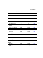
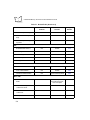
Keypad Operation
Instead of scanning a bar code, you can enter the bar code data using the keypad on the
top of the scanner. To enter numeric data, type the numeric value desired and press
<ENTER>. A beep lets you know that the entry was accepted. See Figure 3-6 on page 322.
To enter alpha characters, press the <Mode> key once to put the scanner in Alpha Mode.
Numeric buttons 1 through 9 are associated with the alpha characters. For example, the
letters a, b and c are located on numeric button 7. Press the button with the letter you desire
- once for the letter a, twice for the letter b, or three times for the letter c. You can continue
entering alpha characters or switch to numerics. Press <ENTER> to save or send the data.
To return to numeric entry mode after entering alpha characters, press the <Mode> key
again. For example, to manually enter 17ABF5, do the following steps:
Data
Action
1
Press numeric button 1.
7
Press numeric button 7.
A
Press <MODE> button once, then numeric
button 7 once. Wait for one second (you will hear a
low pitched beep).
B
Press numeric button 7 twice.
F
Press numeric button 8 three times.
5
Press <MODE> button once, then numeric
button 5 once, then <ENTER>.
Every time you press the button with the letter you desire, you hear a low-pitched beep to
let you know that the entry was registered. Although the entry is registered, it has not been
transferred to the host yet. A high-pitched beep lets you know that the entry has been
transferred to the host.
To return to numeric mode, press the Mode key again. Pressing the Enter key saves the
data.
3-21
P460/P360 Memory Scanners Product Reference Guide
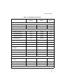
To put a decimal point (.) into numeric data, type in the numbers before the decimal point,
then press the mode key, press the decimal, and press the mode key again. Now resume
typing in the values to the right of the decimal.
To enter a dash (-), press the mode key once, then the zero (0) key twice.
To enter a blank space ( ), press the mode key once, then the zero (0) key three times.
The Function key in combination with a numeric key can be programmed to launch an
operation, such as allowing you to review batch records. To use the Function key to review
batch records, press the <FUNC> key, release it, and then press the <2> key. For more
information on how to program these keys for additional tasks and operations, refer to the
MCL Designer User’s Guide p/n 70-37689-XX.
Figure 3-6. Phaser Keypad
3-22
Operation
Troubleshooting
Refer to Appendix B, Messages and Error Codes for additional troubleshooting information.
Nothing happens when you follow the operating
instructions?
You Should
•
Check that the power supply is attached to the cradle or to the cable.
•
Check for loose cable connections at the scanner, cradle, AC power supply, or host
device.
•
Check the scanner’s battery.
•
Make sure the device is programmed to read the type of bar code you want to scan.
•
Check the symbol to make sure it is not defaced.
•
Try scanning similar symbols of the same code type.
•
Be sure you are within the proper scanning range.
•
Reboot the scanner (hold down the ENTER key for about 10-20 seconds) and try
scanning again.
The scanner emits transmit errors (error beeps after
decode)?
You Should
•
Check that the scanner is powered up and that its cable connections are secure.
•
Be sure the cable connection to the host is secure.
•
Check that the appropriate host type is selected.
Note: If after performing these checks the symbol still does not scan,
contact your distributor or call the Symbol Support Center. See page
xi for the telephone number.
3-23
P460/P360 Memory Scanners Product Reference Guide
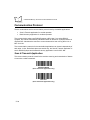
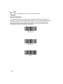
The scanner does not decode the bar codes in the system
menu section?
Your scanner firmware does not support the system menu scanning bar codes feature.
You Should
Enter the system menu using the keypad. See System Menu on page 3-7.
The scanner does not decode the bar codes in the parameter
menus section (Chapter 5, Parameter Menus)?
You Should
Enter the system menu using the keypad. See System Menu on page 3-7. Go to Parameter
Control on page 3-12.
3-24
Chapter 4
Maintenance And Specifications
Introduction
This chapter explains how to maintain your scanner and the specifications for it.
Maintenance
!
Do not allow any abrasive material to touch the scanner window.
!
Remove any dirt particles with a damp cloth.
!
Wipe the scanner window using a damp cloth, and if necessary, a non-ammonia
based detergent.
!
Do not spray water or other cleaning liquids directly into the scanner window.
!
If the contacts between the scanner and cradle become dirty, clean them with
either a pencil eraser or a cotton swab dampened with alcohol.
!
If a significant decrease in battery life is noticed and does not correspond to
increased usage, consider replacing the battery.
Changing the Battery
Once a battery is fully charged, it will generally last up to 12 hours without being returned
to the cradle. By returning it to the cradle during the day, you extend this time.
Removing the Battery
1. Slide the battery compartment release switch down.
4-1
P460/P360 Memory Scanners Product Reference Guide
2. Remove the battery compartment cover.
Battery
Compartment
Cover
Battery
Release Switch
Figure 4-1. Removing the Battery Compartment Cover
3. Slide the battery towards the bottom of the scanner.
4. Pull the bottom of the battery out and away from the scanner.
Figure 4-2. Pulling the Battery Out
Replacing the Battery
1. Seat the battery fully in the scanner.
2. Slide it up in the handle.
3. Replace the battery compartment cover.
4. Slide the release latch up to secure the cover in place.
4-2
Maintenance And Specifications
Charge Status LED Indications
The LED indicator on the cradle uses flashing patterns to display the charger status, as
shown in the table below.
Table 4-1. Cradle LED Indications
LED
Status
Off
The scanner is not in the cradle or has not been
properly inserted into the cradle.
Blinking Slowly
The scanner is properly seated in the cradle and
charging will begin shortly.
Blinking Rapidly
The battery is actively charging.
On
Battery charging is complete.
Accessories
Required Accessories
Phaser scanners are sent as a package with required accessories. Optional accessories
are available at extra cost.
Optional Accessories
Optional accessories include various stands and holders, which are supplied at extra cost.
Additional units of standard accessories may also be purchased at extra cost.
One such optional accessory is the IntelliStand, which permits hands-free operation of the
Phaser scanner. It permits the Phaser to scan continuously and automatically read a bar
code when one is presented in front of the scanner. The Phaser must be operating from a
cable with an external power supply to work with the IntelliStand, as it cannot work with
battery power under these conditions. For more information about the IntelliStand, refer to
the IntelliStand Quick Reference Guide, p/n 70-11567-xx.
4-3
P460/P360 Memory Scanners Product Reference Guide
Technical Specifications
Table 4-2.Technical Specifications for P460/P360 1D Scann er
Item
Description
Decode Capability
UPC/EAN, Bookland EAN, Code 11, Code 39, Code 39 Full ASCII, Trioptic Code 39,
Code 93, Codabar, Interleaved 2 of 5, Code 128, EAN 128, Discrete 2 of 5, MSI
Plessey, and Coupon Code with auto-discriminate between all of the above code types
except for Code 39 and Code 39 Full ASCII.
Scanner Beeper Operation
User-selectable: Enabled, Disabled.
Scan Repetition Rate
36 (± 5) scans/sec (bidirectional)
Roll (Skew) Tolerance
± 30° from normal
Pitch
± 65° from normal
Yaw
± 60° from normal
Decode Depth of Field
See P460/P360 1D Scanner Decode Zone on page 3-18.
Print Contrast Minimum
20% absolute dark/light differential, measured at the wavelength of the laser diode.
Ambient Light Immunity
Artificial Lighting
450 ft. candles
Sunlight
10,000 ft. candles
4844 lux
107,644 lux
(@8 in. (20 cm) on low density bar codes)
Operating Temperature
P460: 32° to 104°F
P360: -4° to 122°F
0° to 40°C
-20° to 50°C
Storage Temperature
-40° to 158°F
-40° to 70°C
Humidity
5% to 95% (non-condensing)
Durability (Scanner)
P460: 5-ft. (1.5 m)
P360: 6-ft. (1.8 m)
Drop to concrete over entire temperature range
Sealing
P360: All components sealed to IP 54 specification against wind blown dust and rain
Dimensions
Height
7.0 in. (17.8 cm)
Width
9.2 in. (13.5 cm)
Depth
3.5 in. (9.8 cm)
Laser Classifications
4-4
CDRH Class II
EN 60825 Class 2
IEC 825 Class 2
Maintenance And Specifications
Table 4-3.Technical Specifications for P460/P360 2D Scann er
Item
Description
Decode Capability
PDF417, MicroPDF417, UPC-A, UPC-E, EAN 8, Ean 13, Code 39, Tri-Optic Code
39, Code 93, Discrete 2 of 5, Bookland EAN, UPC Coupon Code, Code 39 Full ASCII,
Code 128, Interleaved 2 of 5, Codabar, UCC.EAN 128 with full auto-discrimination
between all Symbologies, MSI Plessey, Code 11.
Scanner Beeper Operation
User-selectable: Enabled, Disabled.
Scan Element Type
Raster Scanning
Light Source
650 nm laser diode/1.2 mW max
Scan Rate
560 scans/sec
Frame Rate
25 frames/sec
Optical Resolution
Minimum X-dimension: 1D=6.0 mil (0.15 mm); 2D=6.6 mil (0.17 mm)
Minimum Y-dimension: 3X
Minimum Reflectance
Difference
25% (1D symbologies)
35% (PDF417) measured at 650 nm
Decode Depth of Field
See P460/P360 2D Scanner Decode Zone on page 3-19.
Ambient Light Immunity
Artificial Lighting
450 ft. candles
Sunlight
8,000 ft. candles
4844 lux
86,111 lux
(@8 in. (20 cm) on low density bar codes)
Operating Temperature
P460: 32° to 104°F
P360: -4° to 122°F
0° to 40°C
-20° to 50°C
Storage Temperature
-40° to 158°F
-40° to 70°C
Humidity
5% to 95% (non-condensing)
Durability (Scanner)
P460: 5-ft. (1.5 m)
P360: 6-ft. (1.8 m)
Drop to concrete over entire temperature range
Sealing
P360: All components sealed to IP 54 specification against wind blown dust and rain
Dimensions
Height
7.0 in. (17.8 cm)
Width
9.2 in. (13.5 cm)
Depth
3.5 in. (9.8 cm)
Laser Classifications
CDRH Class II
EN 60825 Class 2
IEC 825 Class 2
4-5
P460/P360 Memory Scanners Product Reference Guide
Pin-outs
Cradle
The following table shows the pin-outs for both COM1 and COM2 on the cradle.
Table 4-4. Cradle Pin-outs
Pin
4-6
Cradle
1
BREQ
2
VCC (out of cradle)
3
Ground
4
Synapse Data
5
Synapse Clock
6
RXD (into cradle)
7
TXD (out of cradle)
8
BACK
9
CTS
10
RTS
Maintenance And Specifications
Scanner
The following table shows the pin-outs for the scanner.
Table 4-5. Scanner Pin-outs
Pin
Scanner
1
Not Used
2
Power (+9V) 1
3
GND
4
Synapse Data
5
Synapse Clock
6
RXD (into scanner)
7
TXD (out of scanner)
8
Enable Charging 2
9
CTS
10
RTS
1.
1D
Scanner:
2D
Battery Charging:
No
Yes
No
Yes
Requires +9V @:
250mA
1A
350mA
1A
2. If Pin 8 is connected to Pin 2 the scanner battery charges;
make sure you use a +9V @ 1 Amp power supply. If Pin 8
is not connected to Pin 2, the scanner operates but the
scanner battery does not charge.
4-7
P460/P360 Memory Scanners Product Reference Guide
Beeper Indications
Table 4-6. Beeper Indications
Beeper Sequence
Indication
Standard Use
Short high tone
A bar code symbol was decoded (if decode beeper is enabled).
4 Beeps - long low tone
A transmission error has been detected in a scanned symbol. The
data is ignored. This occurs if a unit is not properly configured.
Check option settings.
5 Beeps - low tone
Convert or format error.
Hi/hi/hi/lo tone
RS-232 receive error.
4 Beeps - short hi
Battery requires recharging.
Short low/Short high tone
The Scanner detected external power supplied to it by the cradle or
a cable.
Short high/Short low tone
External power has been removed from the scanner.
Parameter Menu Scanning
Short high tone
Correct entry scanned or correct menu sequence performed.
Long low/Long high tone
Input error, incorrect bar code or “Cancel” scanned, wrong entry,
incorrect bar code programming sequence; remain in program
mode.
Hi/lo tone
Keyboard parameter selected. Enter value using bar code keypad.
Hi/lo/hi/lo tone
Successful program exit with change in the parameter setting.
4-8
Chapter 5
Parameter Menus
Introduction
This chapter has the optional parameter bar codes necessary to program the Phaser
scanner.
Operational Parameters
The Phaser is shipped with the settings shown in Table 5-1. These default values are stored
in non-volatile memory and are preserved even when the scanner is powered down. You
can change these default values by scanning the appropriate bar codes included in this
manual. These new values replace the standard default values in memory. The default
parameter values can be recalled by scanning the bar code in the section Set Default
Parameter on page 5-9.
The scanner automatically detects which cable it is attached to, either an RS-232 or a
Synapse cable. If it is attached to an RS-232 cable and has either an ICL, Nixdorf, or Fujitsu
host interface, then scan the appropriate bar code from page 5-13 after power up. Any other
host interface works with the default setting.
If it is attached to a Synapse cable, plug everything together as described on page 2-6 and
then follow the directions that come with the Synapse cable for setting up the host interface.
5-1
P460/P360 Memory Scanners Product Reference Guide
The following table lists the defaults for all parameters. If you wish to change any option,
scan the appropriate bar code(s).
Table 5-1. DefaultTabl e
Parameter
1D P460/P360
Defaults
2D P460/P360
Defaults
Page
Number
All Defaults
All Defaults
5-9
Scan & Transmit Application
RS232/Synapse
RS232/Synapse
5-10
Batch/Inventory Application
MCL-Net
MCL-Net
5-11
Standard
Standard
5-12
10 seconds
10 seconds
5-15
Forward Slash (/)
Forward Slash (/)
5-16
12 Hour
12 Hour
5-17
Decimal Point (.)
Decimal Point (.)
5-18
MM/DD/YYYY
MM/DD/YYYY
5-19
Enable
Enable
5-20
3.0 seconds
3.0 seconds
5-21
Time Delay to Low Power
Mode
N/A
30 seconds
5-22
Time Out Between Same
Symbols
N/A
0.6 seconds
5-23
Time Out Between Different
Symbols
N/A
0 seconds
5-23
High Frequency
High Frequency
5-25
Set Default Parameter
Communication Protocol
RS232 Host Type
Sleep Time
Date Separator
Hour Type
Decimal Separator
Date Format
Key Click
Laser On Time
Scan Stand Options
Beeper Options
Beeper Tone
5-2
Parameter Menus
Table 5-1. DefaultTable (Continued)
Parameter
1D P460/P360
Defaults
2D P460/P360
Defaults
Page
Number
High
High
5-26
Power Detect Beep
Enable
Enable
5-27
Beep After Good Decode
Enable
Enable
5-28
Disable
Disable
5-29
UPC-A
Enable
Enable
5-30
UPC-E
Enable
Enable
5-30
UPC-E1
Disable
Disable
5-30
EAN-8
Enable
Enable
5-31
EAN-13
Enable
Enable
5-31
Bookland EAN
Disable
Disable
5-32
Decode UPC/EAN
Supplementals
Ignore
Ignore
5-33
7
7
5-34
Transmit UPC-A Check Digit
Enable
Enable
5-35
Transmit UPC-E Check Digit
Enable
Enable
5-35
Transmit UPC-E1 Check
Digit
Enable
Enable
5-35
UPC-A Preamble
System Character
System Character
5-36
UPC-E Preamble
System Character
System Character
5-37
Beeper Volume
Decode Options
Transmit “No Read”
Message
UPC/EAN
Decode UPC/EAN
Supplemental Redundancy
5-3
P460/P360 Memory Scanners Product Reference Guide
Table 5-1. DefaultTable (Continued)
Parameter
1D P460/P360
Defaults
2D P460/P360
Defaults
Page
Number
System Character
System Character
5-38
Convert UPC-E to A
Disable
Disable
5-39
Convert UPC-E1 to A
Disable
Disable
5-40
EAN-8 Zero Extend
Disable
Disable
5-41
Type is EAN-13
Type is EAN-13
5-42
Disable
Disable
5-43
Code 128
Enable
Enable
5-44
UCC/EAN-128
Enable
Enable
5-45
N/A
Disable
5-46
Code 39
Enable
Enable
5-47
Trioptic Code 39
Disable
Disable
5-48
Set Length(s) for Code 39
2 to 55
2 to 55
5-50
Code 39 Check Digit
Verification
Disable
Disable
5-51
Transmit Code 39 Check
Digit
Disable
Disable
5-52
Code 39 Full ASCII
Conversion
Disable
Disable
5-53
Convert Code 39 to Code 32
Disable
Disable
5-54
Code 32 Prefix
Disable
Disable
5-55
UPC-E1 Preamble
Convert EAN-8 to EAN-13
Type
UPC/EAN Coupon Code
Code 128
ISBT-128
Code 39
5-4
Parameter Menus
Table 5-1. DefaultTable (Continued)
Parameter
1D P460/P360
Defaults
2D P460/P360
Defaults
Page
Number
Disable
Disable
5-56
4-55
4-55
5-57
Enable
Enable
5-59
14
14
5-60
I 2 of 5 Check Digit
Verification
Disable
Disable
5-62
Transmit I 2 of 5 Check Digit
Disable
Disable
5-63
Convert I 2 of 5 to EAN 13
Disable
Disable
5-64
Disable
Disable
5-65
12
12
5-66
Disable
Disable
5-68
5-55
5-55
5-70
CLSI Editing
Disable
Disable
5-71
NOTIS Editing
Disable
Disable
5-72
Disable
Disable
5-73
Any Length
Any Length
5-75
Code 93
Code 93
Set Length(s) for Code 93
Interleaved 2 of 5
Interleaved 2 of 5
Set Length(s) for I 2 of 5
Discrete 2 of 5
Discrete 2 of 5
Set Length(s) for D 2 of 5
Codabar
Codabar
Set Lengths for Codabar
MSI Plessey
MSI Plessey
Set Length(s) for MSI
Plessey
5-5
P460/P360 Memory Scanners Product Reference Guide
Table 5-1. DefaultTable (Continued)
Parameter
1D P460/P360
Defaults
2D P460/P360
Defaults
Page
Number
One
One
5-76
Disable
Disable
5-77
MSI Plessey Check Digit
Algorithm
Mod 10/Mod 10
Mod 10/Mod 10
5-78
Enable/Disable PDF417
N/A
Enable
5-79
Scanning Mode
N/A
Smart Raster
5-80
Raster Height
N/A
15
5-81
Raster Expansion
N/A
11
5-81
Aiming Mode
N/A
Slab Raster
5-83
Enable/Disable Micro PDF
N/A
Disable
5-84
Code 128 Emulation
N/A
Enable
5-85
UCC/EAN-128 Emulation
N/A
Ignore Linked Symbols
5-86
Macro PDF Transmit/Decode
Mode
N/A
Buffer All Symbols/
Transmit Macro PDF
when Complete
5-88
Transmit Each Symbol in
Codeword Format
N/A
Disable
5-90
Transmit Unknown
Codewords
N/A
Disable
5-91
Escape Character
N/A
None
5-92
MSI Plessey Check Digits
Transmit MSI Plessey Check
Digit
PDF
Micro PDF
Macro PDF
5-6
Parameter Menus
Table 5-1. DefaultTable (Continued)
Parameter
1D P460/P360
Defaults
2D P460/P360
Defaults
Page
Number
Delete Character Set ECIs
N/A
Enable
5-93
ECI Decoder
N/A
Enable
5-94
Transmit File Name
N/A
Disable
5-95
Transmit Block Count
N/A
Disable
5-96
Transmit Time Stamp
N/A
Disable
5-96
Transmit Sender
N/A
Disable
5-97
Transmit Addressee
N/A
Disable
5-97
Transmit Checksum
N/A
Disable
5-98
Transmit File Size
N/A
Disable
5-98
Transmit Macro PDF Control
Header
N/A
Disable
5-99
Last Block Marker
N/A
Disable
5-99
Flush Macro Buffer
N/A
N/A
5-100
Abort Macro PDF Entry
N/A
N/A
5-100
Linear Code Type Security
Levels
1
2
5-101
Bi-directional Redundancy
Disable
Disable
5-103
UPC/EAN Security Levels
0
0
5-104
ECI
Transmit Macro PDF User-Selected Field
Security Options
RS-232C
5-7
P460/P360 Memory Scanners Product Reference Guide
Table 5-1. DefaultTable (Continued)
Parameter
1D P460/P360
Defaults
2D P460/P360
Defaults
Page
Number
Standard
Standard
5-12
Baud Rate
9600
9600
5-107
Parity
None
None
5-108
Disable
Do Not Check
5-109
Hardware Handshaking
None
None
5-110
Software Handshaking
None
None
5-112
Host Serial Response Timeout
2 Sec.
2 Sec.
5-114
Low
Low
5-115
Stop Bit Select
1
1
5-116
ASCII Format
8-Bit
8-Bit
5-116
Disable
Disable
5-117
0
0
5-117
38400
38400
5-118
Disable
Disable
5-120
001
001
5-120
MCL-Net Transmit Retries
3
3
5-121
MCL-Net Frame Timeout
500 ms
500 ms
5-121
RS-232 Host Type
Check Receive Errors
RTS Line State (cable use
only)
Beep on <BEL>
Intercharacter Delay
MCL-Net
MCL-Net Baud Rate
MCL-Net Hex Addressing
Mode
Scanner Address
5-8
Parameter Menus
Set Default Parameter
Scanning this bar code returns all parameters to the values listed in Table 5-1.
SET ALL DEFAULTS
5-9
P460/P360 Memory Scanners Product Reference Guide
Communication Protocol
The bar codes below set the communication protocol used by the default applications.
!
Scan & Transmit application for corded operation
!
Batch/Inventory application for cordless operation
The communication options are RS232/Synapse or MCL-Net. If you select RS232/
Synapse, the scanner automatically identifies whether an RS232 or Synapse interface is
required. MCL-Net allows the scanner to communicate with a host running MCL-Link or
MCL-Link Lite.
The communication protocols for the two default applications can be set independently of
each other. In fact, the default values are set this way; the Scan & Transmit application is
set for RS232/Synapse and the Batch/Inventory application is set for MCL-Net.
Scan & Transmit Application
This communication protocol is used for the real time scanning and transmission of data to
a host when a cable is attached.
RS232/SYNAPSE
(Scan & Transmit application only)
MCL-NET
(Scan & Transmit application only)
5-10
Parameter Menus
Batch/Inventory Application
This communication protocol is used when you are ready to transmit your batch records
(data collected when the scanner was used without a cable attached) to a host.
RS232/SYNAPSE
(Batch/Inventory application only)
MCL-NET
(Batch/Inventory application only)
Note: These communication protocol parameters only work with the
default applications and will not work with applications created with
MCL-Designer.
5-11
P460/P360 Memory Scanners Product Reference Guide
Host Type
RS-232 Host Types
Most RS-232C hosts work fine with the default settings, however, three RS-232C hosts are
set up with their own parameter default settings. Selecting the ICL, Fujitsu or Nixdorf RS232C host interface sets the defaults listed below. These defaults take precedence over
Standard RS-232 defaults. So, if you select the Fujitsu RS-232C first, and then select
the Standard RS-232 defaults, the Fujitsu defaults still take precedence. To return to
the factory set defaults, scan the SET ALL DEFAULTS bar code on page 5-9.
Table 5-2.Terminal Specific RS-232C
Parameter
Standard
ICL
FUJITSU
NIXDORF
Mode A/
Mode B
Transmit Code ID
No
Yes
Yes
Yes
Data Transmission Format
Data as is
Data/Suffix
Data/Suffix
Data/Suffix
Suffix
CR/LF
CR
CR
CR
Baud Rate
9600
9600
9600
9600
Parity
None
Even
None
Odd
Hardware Handshaking
None
RTS/CTS
Option 3
None
RTS/CTS
Option 3
Software Handshaking
None
None
None
None
Serial Response Time-out
2 Sec.
9.9 Sec.
2 Sec.
9.9 Sec.
Stop Bit Select
One
One
One
One
ASCII Format
8-Bit
8-Bit
8-Bit
8-Bit
Beep On <BEL>
Disabled
Disabled
Disabled
Disabled
RTS Line State
Low
High
Low
*Low = No
data to send
*In the Nixdorf Mode B, if CTS is Low, transmission of scan data is disabled. When CTS is High,
bar code data is transmitted to the host.
5-12
Parameter Menus
Scan the appropriate bar code below to select an RS-232C Host Interface.
STANDARD RS-232C
ICL RS-232C
NIXDORF RS-232C Mode A
NIXDORF RS-232C Mode B
FUJITSU RS-232C
5-13
P460/P360 Memory Scanners Product Reference Guide
Code ID Characters for RS232C Host Types
Selecting the ICL, Fujitsu, or Nixdorf RS-232C host interface enables the transmission of
Code ID Characters as listed below. These Code ID Characters are not programmable and
are separate from the Transmit Code ID feature. The Transmit Code ID feature should not
be enabled for these hosts.
Table 5-3.Terminal Specific Code ID Characters
ICL
5-14
FUJITSU
NIXDORF
UPC-A
“A”
“A”
“A”
UPC-E
“E”
“E”
“C0”
EAN-8
“FF”
“FF”
“B”
EAN-13
“F”
“F”
“A”
Code 39
“C” <len>
None
“M”
Codabar
“N” <len>
None
“N”
Code 128
“L” <len>
None
“K”
I 2 of 5
“I” <len>
None
“I”
Code 93
None
None
“L”
D 2 of 5
“H” <len>
None
“H”
UCC/EAN 128
“L” <len>
None
“P”
MSI/Plessey
None
None
“O”
Bookland EAN
“F”
“F”
“A”
Trioptic
None
None
None
Parameter Menus
Sleep Time
Scan the bar code below to select how long the scanner will “stay awake” (not power down)
in seconds after a trigger pull or a key press. First scan this bar code, then enter a range
from 05 to 32, using the Numeric Bar Codes on page 5-122. It can stay awake from 5
seconds to 32 seconds.
Note: Allowing the scanner to stay awake longer than originally
programmed may effect the battery life time for that session before
needing a charge.
SLEEP TIME (RANGE OF 5 TO 32 SECONDS)
5-15
P460/P360 Memory Scanners Product Reference Guide
Date Separator
Scan the appropriate bar code below to select which separator to use when displaying the
date. Choose FORWARD SLASH, DASH, COLON or NONE.
FORWARD SLASH (/)
DASH (-)
COLON (:)
NONE
5-16
Parameter Menus
Hour Type
Scan the appropriate bar code below to select how to display the hour and transmit it to the
host device. Choose 12 HOUR (6:00 pm) or 24 HOUR (18:00).
24 HOUR
12 HOUR
5-17
P460/P360 Memory Scanners Product Reference Guide
Decimal Separator
Scan the appropriate bar code below to select what separator to display when you hit the
decimal point key on the keypad. Choose DECIMAL POINT (.) or COMMA (,).
DECIMAL POINT (.)
COMMA (,)
5-18
Parameter Menus
Date Format
Scan the appropriate bar code below to select how to format the date when it is displayed
and transmitted to the host device. Choose MM/DD/YYYY or DD/MM/YYYY.
MM/DD/YYYY
DD/MM/YYYY
5-19
P460/P360 Memory Scanners Product Reference Guide
Key Click
Scan the appropriate bar code below to select whether the keypad click is enabled or not.
Choose ENABLE or DISABLE.
ENABLE
DISABLE
5-20
Parameter Menus
Laser On Time
This parameter sets the maximum time decode processing continues during a scan
attempt. It is programmable in 0.1 second increments from 0.5 to 9.9 seconds.
Scan the bar code below to set a Laser On Time. Next scan two numeric bar codes
beginning on page 5-122 that correspond to the desired time. Time less than 1.0 second
must have a leading zero. For example, to set a Time On of 0.5 seconds, scan the bar
code below, then scan the “0” and “5” bar codes. If you make an error, or wish to change
your selection, scan CANCEL on page 5-124.
LASER ON TIME
5-21
P460/P360 Memory Scanners Product Reference Guide
Scan Stand Options
The Scan Stand feature is supported only when the cord is attached to the scanner.
Time Delay to Low Power Mode
For extending laser life in scan stand mode, select the time the scanner remains active
following a successful decode. Selectable options include 30 seconds, 1 minute, 2 minutes,
3 minutes. To awaken the scanner in low power mode, present a symbol to the scan path.
A successful decode restores it to normal blinking. The recommended delay is 30 seconds.
30 Second Delay
2 Minute Delay
1 Minute Delay
3 Minute Delay
Timeout Between Decodes
Timeout Between Decodes, Same Symbol is used in scan stand mode to prevent the
beeper from continuously beeping when a symbol is left in the scanner’s field of view. It is
programmable in 0.1 second increments from 0.0 to 9.9 seconds. The recommended
interval is 0.6 seconds.
Timeout Between Decodes, Different Symbols is used in scan stand mode to prevent the
beeper from beeping when a different symbol appears in the scanner’s field of view before
the timeout period between decodes has expired. This is programmable in 0.1 second
increments from 0.0 to 9.9 seconds. The recommended value is 0.0 seconds.
5-22
Parameter Menus
Select the timeouts between decodes for the same or different symbols.
1. Scan the option bar code you wish to set.
2. Scan two bar codes on the next page which correspond to the desired interval, in
0.1 second increments.
3. If you make an error, or wish to change your selection, scan CANCEL.
Timeout Between Decodes The Same Symbol
Timeout Between Decodes Different Symbols
5-23
P460/P360 Memory Scanners Product Reference Guide
Timeout Between Decodes (Continued)
0
1
2
3
4
5
6
7
8
9
Cancel
5-24
Parameter Menus
Beeper Options
Beeper Tone
Scan the appropriate bar code below to select a decode beep frequency (tone). Choose
LOW FREQUENCY, MEDIUM FREQUENCY, or HIGH FREQUENCY.
LOW FREQUENCY
MEDIUM FREQUENCY
HIGH FREQUENCY
5-25
P460/P360 Memory Scanners Product Reference Guide
Beeper Volume
Scan the appropriate bar code below to select a beeper volume. Choose LOW VOLUME,
MEDIUM VOLUME, or HIGH VOLUME.
LOW VOLUME
MEDIUM VOLUME
HIGH VOLUME
5-26
Parameter Menus
Power Detect Beep
Scan the appropriate barcode below to enable or disable the Power Detection Beep.
POWER DETECT BEEP DISABLED
POWER DETECT BEEP ENABLED
5-27
P460/P360 Memory Scanners Product Reference Guide
Beep After Good Decode
Scan the appropriate bar code below to select whether or not the scanner beeps after a
good decode. If DO NOT BEEP is selected, the beeper still operates during parameter
menu scanning and indicates error conditions.
BEEP AFTER GOOD DECODE
DO NOT BEEP AFTER GOOD DECODE
5-28
Parameter Menus
Decode Options
Transmit “No Read” Message
Scan the appropriate bar code below to select whether or not a “No Read” message is
transmitted. When enabled, if a symbol does not decode, “NR” is transmitted. When
disabled, if a symbol does not read, nothing is sent to the host.
ENABLE NO READ
DISABLE NO READ
5-29
P460/P360 Memory Scanners Product Reference Guide
Enable/Disable UPC-E/UPC-A/UPC-E1
Scan the appropriate bar code below to enable or disable UPC-E or UPC-A.
5-30
ENABLE UPC-E
DISABLE UPC-E
ENABLE UPC-A
DISABLE UPC-A
ENABLE UPC-E1
DISABLE UPC-E1
Parameter Menus
Enable/Disable EAN-8/EAN-13
Scan the appropriate bar code below to enable or disable EAN-8 or EAN-13.
ENABLE EAN-8
DISABLE EAN-8
ENABLE EAN-13
DISABLE EAN-13
5-31
P460/P360 Memory Scanners Product Reference Guide
Enable/Disable Bookland EAN
Scan the appropriate bar code below to enable or disable Bookland EAN.
ENABLE BOOKLAND EAN
DISABLE BOOKLAND EAN
5-32
Parameter Menus
Decode UPC/EAN Supplementals
Supplementals are characters (either 2 or 5) that are added on according to specific code
format conventions (e.g., UPC A+2, UPC E+2, EAN 8+2). Three options are available.
!
If Decode UPC/EAN with supplementals is selected, UPC/EAN symbols without
supplemental characters are not decoded.
!
If Ignore UPC/EAN with supplementals is selected, UPC/EAN symbols with
supplemental characters are decoded and the supplemental characters are
ignored.
!
If Autodiscriminate UPC/EAN supplementals is selected, UPC/EAN symbols,
either with or without supplementals, are decoded. If selected, choose an
appropriate Decode UPC/EAN Supplemental Redundancy value from the next
page.
Note: To minimize the risk of invalid data transmission, select whether to
read or ignore supplemental characters.
DECODE UPC/EAN WITH SUPPLEMENTALS
IGNORE UPC/EAN WITH SUPPLEMENTALS
AUTODISCRIMINATE UPC/EAN SUPPLEMENTALS
5-33
P460/P360 Memory Scanners Product Reference Guide
Decode UPC/EAN Supplemental Redundancy
With Autodiscriminate UPC/EAN Supplementals selected, this option adjusts the number
of times a symbol without supplementals is decoded before transmission. The range is from
two to 20 times. Five or above is recommended when decoding a mix of UPC/EAN symbols
with and without supplementals, and the autodiscriminate option is selected.
Scan the bar code below to select a decode redundancy value. Next scan two numeric bar
codes beginning on page 5-122. Single digit numbers must have a leading zero. If you
make an error, or wish to change your selection, scan CANCEL on page 5-124.
DECODE UPC/EAN
SUPPLEMENTAL REDUNDANCY
5-34
Parameter Menus
Transmit UPC-A/UPC-E/UPC-E1 Check Digit
Scan the appropriate bar code below to transmit the symbol with or without the UPC-A,
UPC-E, or UPC-E1 check digit.
TRANSMIT UPC-A CHECK DIGIT
DO NOT TRANSMIT UPC-A CHECK DIGIT
TRANSMIT UPC-E CHECK DIGIT
DO NOT TRANSMIT UPC-E CHECK DIGIT
TRANSMIT UPC-E1 CHECK DIGIT
DO NOT TRANSMIT UPC-E1 CHECK DIGIT
5-35
P460/P360 Memory Scanners Product Reference Guide
UPC-A Preamble
Three options are given for lead-in characters for UPC-A symbols transmitted to the host
device: transmit system character only, transmit system character and country code (“0” for
USA), and no preamble transmitted. The lead-in characters are considered part of the
symbol.
NO PREAMBLE
(<DATA>)
SYSTEM CHARACTER
(<SYSTEM CHARACTER> <DATA>)
SYSTEM CHARACTER & COUNTRY CODE
(< COUNTRY CODE> <SYSTEM CHARACTER> <DATA>)
5-36
Parameter Menus
UPC-E Preamble
Three options are given for lead-in characters for UPC-E symbols transmitted to the host
device: Transmit system character only, transmit system character and country code (“0”
for USA), and no preamble transmitted. The lead-in characters are considered part of the
symbol.
NO PREAMBLE
(<DATA>)
SYSTEM CHARACTER
(<SYSTEM CHARACTER> <DATA>)
SYSTEM CHARACTER & COUNTRY CODE
(< COUNTRY CODE> <SYSTEM CHARACTER> <DATA>)
5-37
P460/P360 Memory Scanners Product Reference Guide
UPC-E1 Preamble
Three options are given for lead-in characters for UPC-E1 symbols transmitted to the host
device: Transmit system character only, transmit system character and country code (“0”
for USA), and no preamble transmitted. The lead-in characters are considered part of the
symbol.
NO PREAMBLE
(<DATA>)
SYSTEM CHARACTER
(<SYSTEM CHARACTER> <DATA>)
SYSTEM CHARACTER & COUNTRY CODE
(< COUNTRY CODE> <SYSTEM CHARACTER> <DATA>)
5-38
Parameter Menus
Convert UPC-E to UPC-A
This parameter converts UPC-E (zero suppressed) decoded data to UPC-A format before
transmission. After conversion, data follows UPC-A format and is affected by UPC-A
programming selections (e.g., Preamble, Check Digit).
Scanning DO NOT CONVERT UPC-E TO UPC-A allows you to transmit UPC-E (zero
suppressed) decoded data.
CONVERT UPC-E TO UPC-A
(ENABLE)
DO NOT CONVERT UPC-E TO UPC-A
(DISABLE)
5-39
P460/P360 Memory Scanners Product Reference Guide
Convert UPC-E1 to UPC-A
This parameter converts UPC-E1 decoded data to UPC-A format before transmission. After
conversion, data follows UPC-A format and is affected by UPC-A programming selections
(e.g., Preamble, Check Digit).
Scanning DO NOT CONVERT UPC-E1 TO UPC-A allows you to transmit UPC-E1
decoded data.
CONVERT UPC-E1 TO UPC-A
(ENABLE)
DO NOT CONVERT UPC-E1 TO UPC-A
(DISABLE)
5-40
Parameter Menus
EAN Zero Extend
If this parameter is enabled, five leading zeros are added to decoded EAN-8 symbols to
make them compatible in format to EAN-13 symbols.
Disabling this parameter returns EAN-8 symbols to their normal format.
ENABLE EAN ZERO EXTEND
DISABLE EAN ZERO EXTEND
5-41
P460/P360 Memory Scanners Product Reference Guide
Convert EAN-8 to EAN-13 Type
When EAN Zero Extend is enabled, this parameter gives you the option of labeling the
extended symbol as either an EAN-13 bar code, or an EAN-8 bar code.
When EAN Zero Extend is disabled, this parameter has no effect on bar code data.
TYPE IS EAN-13
TYPE IS EAN-8
5-42
Parameter Menus
UPC/EAN Coupon Code
When this parameter is enabled, the Phaser decodes UPC-A, UPC-A with 2 supplemental
characters, UPC-A with 5 supplemental characters, and UPC-A/EAN128 bar codes.
AUTODISCRIMINATE UPC/EAN SUPPLEMENTALS on page 5-33 must be enabled.
ENABLE UPC/EAN COUPON CODE
DISABLE UPC/EAN COUPON CODE
5-43
P460/P360 Memory Scanners Product Reference Guide
Enable/Disable Code 128
Scan the appropriate bar code below to enable or disable Code 128.
ENABLE CODE 128
DISABLE CODE 128
Note: The “|” character and the NULL character cannot be embedded in
the barcode to be scanned when using Code 128.
5-44
Parameter Menus
Enable/Disable UCC/EAN-128
Scan the appropriate bar code below to enable or disable UCC/EAN-128. (See Appendix
A, Bar Code Information for details on UCC/EAN-128.)
ENABLE UCC/EAN-128
DISABLE UCC/EAN-128
Lengths for Code 128
No length setting is required for Code 128. The default setting is Any Length.
5-45
P460/P360 Memory Scanners Product Reference Guide
Enable/Disable ISBT 128 (2D Scanner only)
To enable or disable ISBT 128, scan the appropriate bar code below.
Enable ISBT 128
Disable ISBT 128
5-46
Parameter Menus
Enable/Disable Code 39
Scan the appropriate bar code below to enable or disable Code 39.
ENABLE CODE 39
DISABLE CODE 39
5-47
P460/P360 Memory Scanners Product Reference Guide
Enable/Disable Trioptic Code 39
Trioptic Code 39 symbols always contain six characters. Trioptic Code 39 and Code 39 Full
ASCII cannot be enabled simultaneously. If you get an error beep when enabling Trioptic
Code 39, disable Code 39 Full ASCII and try again. To enable or disable Trioptic Code 39,
scan the appropriate bar code below.
ENABLE TRIOPTIC CODE 39
DISABLE TRIOPTIC CODE 39
5-48
Parameter Menus
Set Lengths for Code 39
Lengths for Code 39 may be set for any length, one or two discrete lengths, or lengths
within a specific range. The length of a code refers to the number of characters (i.e., human
readable characters), including check digit(s) the code contains. If Code 39 Full ASCII is
enabled, Length Within a Range or Any Length are the preferred options.
One Discrete Length - This option allows you to decode only those codes containing a
selected length. For example, if you select Code 39 One Discrete Length, then scan 1, 4,
only Code 39 symbols containing 14 characters are decoded. Numeric bar codes begin
on page 5-122. If you make an error, or wish to change your selection, scan CANCEL
on page 5-124.
CODE 39 - ONE DISCRETE LENGTH
Two Discrete Lengths - This option allows you to decode only those codes containing
two selected lengths. For example, if you select Code 39 Two Discrete Lengths, then
scan 0, 2, 1, 4, only Code 39 symbols containing 2 or 14 characters are decoded.
Numeric bar codes begin on page 5-122. If you make an error, or wish to change your
selection, scan CANCEL on page 5-124.
CODE 39 - TWO DISCRETE LENGTHS
5-49
P460/P360 Memory Scanners Product Reference Guide
Set Lengths for Code 39 (Continued)
Length Within Range - This option allows you to decode a code type within a
specified range. For example to decode Code 39 symbols containing between 4 and
12 characters, first scan Code 39 Length Within Range. Then scan 0, 4, 1 and 2 (single
digit numbers must always be preceded by a leading zero). Numeric bar codes begin on
page 5-122. If you make an error, or wish to change your selection, scan CANCEL on page
5-124.
CODE 39 - LENGTH WITHIN RANGE
Any Length - Scanning this option allows you to decode Code 39 symbols containing any
number of characters.
CODE 39 - ANY LENGTH
5-50
Parameter Menus
Code 39 Check Digit Verification
When enabled, this parameter checks the integrity of a Code 39 symbol to ensure it
complies with specified algorithms.
Only those Code 39 symbols which include a modulo 43 check digit are decoded when this
parameter is enabled.
ENABLE CODE 39 CHECK DIGIT
DISABLE CODE 39 CHECK DIGIT
5-51
P460/P360 Memory Scanners Product Reference Guide
Transmit Code 39 Check Digit
Scan the appropriate bar code below to transmit the data with or without the check digit.
TRANSMIT CODE 39 CHECK DIGIT
(ENABLE)
DO NOT TRANSMIT CODE 39 CHECK DIGIT
(DISABLE)
5-52
Parameter Menus
Enable/Disable Code 39 Full ASCII
Scan the appropriate bar code below to enable or disable Code 39 Full ASCII.
When enabled, the ASCII character set assigns a code to letters, punctuation marks,
numerals, and most control keystrokes on the keyboard.
The first 32 codes are non-printable and are assigned to keyboard control characters such
as BACKSPACE and RETURN. The other 96 are called printable codes because all but
SPACE and DELETE produce visible characters.
Code 39 Full ASCII interprets the bar code special character ($ + % /) preceding a Code
39 character and assigns an ASCII character value to the pair. For example, when Code
39 Full ASCII is enabled and a +B is scanned, it is interpreted as b, %J as ?, and $H
emulates the keystroke BACKSPACE. Scanning ABC$M will output the keystroke
equivalent of ABC ENTER. Refer to the ASCII table in Appendix A.
Code 39 Full ASCII and Trioptic Code 39 cannot be enabled simultaneously. If you get an
error beep when enabling Code 39 Full ASCII, disable Trioptic Code 39 and try again.
The scanner does not autodiscriminate between Code 39 and Code 39 Full ASCII.
ENABLE CODE 39 FULL ASCII
DISABLE CODE 39 FULL ASCII
Note: The “|” character and the NULL character cannot be embedded in
the barcode to be scanned when using Code 39 Full ASCII.
5-53
P460/P360 Memory Scanners Product Reference Guide
Convert Code 39 to Code 32
Scan the appropriate bar code below to enable or disable converting Code 39 to Code 32.
Note: Code 39 must be enabled in order for this parameter to function.
CONVERT CODE 39 TO CODE 32
(ENABLE)
DO NOT CONVERT CODE 39 TO CODE 32
(DISABLE)
5-54
Parameter Menus
Code 32 Prefix
Scan the appropriate bar code below to enable or disable the prefix character “A” to all
Code 32 bar codes.
Note: Convert Code 39 to Code 32 must be enabled for this parameter to
function.
ENABLE CODE 32 PREFIX
DISABLE CODE 32 PREFIX
5-55
P460/P360 Memory Scanners Product Reference Guide
Enable/Disable Code 93
Scan the appropriate bar code below to enable or disable Code 93.
ENABLE CODE 93
DISABLE CODE 93
5-56
Parameter Menus
Set Lengths for Code 93
Lengths for Code 93 may be set for any length, one or two discrete lengths, or lengths
within a specific range. The length of a code refers to the number of characters (i.e., human
readable characters), including check digit(s) the code contains.
One Discrete Length - This option allows you to decode only those codes containing a
selected length. For example, if you select Code 93 One Discrete Length, then scan 1, 4,
only Code 93 symbols containing 14 characters are decoded. Numeric bar codes begin
on page 5-122. If you make an error, or wish to change your selection, scan CANCEL
on page 5-124.
CODE 93 - ONE DISCRETE LENGTH
Two Discrete Lengths - This option allows you to decode only those codes containing two
selected lengths. For example, if you select Code 93 Two Discrete Lengths, then scan 0,
2, 1, 4, only Code 93 symbols containing 2 or 14 characters are decoded. Numeric bar
codes begin on page 5-122. If you make an error, or wish to change your selection, scan
CANCEL on page 5-124.
CODE 93 - TWO DISCRETE LENGTHS
5-57
P460/P360 Memory Scanners Product Reference Guide
Set Lengths for Code 93 (Continued)
Length Within Range - This option allows you to decode a code type within a
specified range. For example to decode Code 93 symbols containing between 4 and
12 characters, first scan Code 93 Length Within Range. Then scan 0, 4, 1 and 2 (single
digit numbers must always be preceded by a leading zero). Numeric bar codes begin on
page 5-122. If you make an error, or wish to change your selection, scan CANCEL on page
5-124.
CODE 93 - LENGTH WITHIN RANGE
Any Length - Scanning this option allows you to decode Code 93 symbols containing any
number of characters.
CODE 93 - ANY LENGTH
5-58
Parameter Menus
Enable/Disable Interleaved 2 of 5
Scan the appropriate bar code below to enable or disable Interleaved 2 of 5.
ENABLE INTERLEAVED 2 OF 5
DISABLE INTERLEAVED 2 OF 5
5-59
P460/P360 Memory Scanners Product Reference Guide
Set Lengths for Interleaved 2 of 5
Lengths for I 2 of 5 may be set for any length, one or two discrete lengths, or lengths within
a specific range. The length of a code refers to the number of characters (i.e., human
readable characters) the code contains and includes check digits.
One Discrete Length - This option allows you to decode only those codes containing a
selected length. For example, if you select I 2 of 5 One Discrete Length, then scan 1, 4,
the only I 2 of 5 symbols decoded are those containing 14 characters. Numeric bar codes
begin on page 5-122. If you make an error, or wish to change your selection, scan
CANCEL on page 5-124.
I 2 of 5 - ONE DISCRETE LENGTH
Two Discrete Lengths - This option allows you to decode only those codes containing two
selected lengths. For example, if you select I 2 of 5 Two Discrete Lengths, then scan 0,
2, 1, 4, the only I 2 of 5 symbols decoded are those containing 2 or 14 characters.
Numeric bar codes begin on page 5-122. If you make an error, or wish to change your
selection, scan CANCEL on page 5-124.
I 2 of 5 - TWO DISCRETE LENGTHS
5-60
Parameter Menus
Set Lengths for Interleaved 2 of 5 (Continued)
Length Within Range - This option allows you to decode a code type within a specified
range. For example to decode I 2 of 5 symbols containing between 4 and 12 characters,
first scan I 2 of 5 Length Within Range. Then scan 0, 4, 1 and 2 (single digit numbers must
always be preceded by a leading zero). Numeric bar codes begin on page 5-122. If you
make an error, or wish to change your selection, scan CANCEL on page 5-124.
I 2 of 5 - LENGTH WITHIN RANGE
Any Length - Scanning this option allows you to decode I 2 of 5 symbols containing any
number of characters.
Note: Selecting this option may lead to mis-decodes for I 2 of 5 codes.
I 2 of 5 - ANY LENGTH
5-61
P460/P360 Memory Scanners Product Reference Guide
I 2 of 5 Check Digit Verification
When enabled, this parameter checks the integrity of an I 2 of 5 symbol to ensure it
complies with a specified algorithm, either USS (Uniform Symbology Specification), or
OPCC (Optical Product Code Council).
DISABLE
USS CHECK DIGIT
OPCC CHECK DIGIT
5-62
Parameter Menus
Transmit I 2 of 5 Check Digit
Scan the appropriate bar code below to transmit the data with or without the check digit.
TRANSMIT I 2 of 5 CHECK DIGIT
(ENABLE)
DO NOT TRANSMIT I 2 of 5 CHECK DIGIT
(DISABLE)
5-63
P460/P360 Memory Scanners Product Reference Guide
Convert I 2 of 5 to EAN-13
This parameter converts a 14 character I 2 of 5 code into EAN-13, and transmits to the host
as EAN-13. In order to accomplish this, the I 2 of 5 code must be enabled, one length must
be set to 14, and the code must have a leading zero and a valid EAN-13 check digit.
CONVERT I 2 of 5 to EAN-13
(ENABLE)
DO NOT CONVERT I 2 of 5 to EAN-13
(DISABLE)
5-64
Parameter Menus
Enable/Disable Discrete 2 of 5
Scan the appropriate bar code below to enable or disable Discrete 2 of 5.
ENABLE DISCRETE 2 OF 5
DISABLE DISCRETE 2 OF 5
5-65
P460/P360 Memory Scanners Product Reference Guide
Set Lengths for Discrete 2 of 5
Lengths for D 2 of 5 may be set for any length, one or two discrete lengths, or lengths within
a specific range. The length of a code refers to the number of characters (i.e., human
readable characters) the code contains, and includes check digits.
One Discrete Length - This option allows you to decode only those codes containing a
selected length. For example, if you select D 2 of 5 One Discrete Length, then scan 1, 4,
the only D 2 of 5 symbols decoded are those containing 14 characters. Numeric bar codes
begin on page 5-122. If you make an error, or wish to change your selection, scan
CANCEL on page 5-124.
D 2 of 5 - ONE DISCRETE LENGTH
Two Discrete Lengths - This option allows you to decode only those codes containing two
selected lengths. For example, if you select D 2 of 5 Two Discrete Lengths, then scan
0, 2, 1, 4, the only D 2 of 5 symbols decoded are those containing 2 or 14 characters.
Numeric bar codes begin on page 5-122. If you make an error, or wish to change your
selection, CANCEL on page 5-124.
D 2 of 5 - TWO DISCRETE LENGTHS
5-66
Parameter Menus
Set Lengths for Discrete 2 of 5 (Continued)
Length Within Range - This option allows you to decode a code type within a
specified range. For example to decode D 2 of 5 symbols containing between 4 and 12
characters, first scan D 2 of 5 Length Within Range. Then scan 0, 4, 1 and 2 (single digit
numbers must always be preceded by a leading zero). Numeric bar codes begin on page
5-122. If you make an error, or wish to change your selection, scan CANCEL on page 5124.
D 2 of 5 - LENGTH WITHIN RANGE
Any Length - Scanning this option allows you to decode D 2 of 5 symbols containing any
number of characters.
Note: Selecting this option may lead to mis-decodes for D 2 of 5 codes.
D 2 of 5 - ANY LENGTH
5-67
P460/P360 Memory Scanners Product Reference Guide
Enable/Disable Codabar
Scan the appropriate bar code below to enable or disable Codabar.
ENABLE CODABAR
DISABLE CODABAR
5-68
Parameter Menus
Set Lengths for Codabar
Lengths for Codabar may be set for any length, one or two discrete lengths, or lengths
within a specific range. The length of a code refers to the number of characters (i.e., human
readable characters) the code contains. It also includes any start or stop characters.
One Discrete Length - This option allows you to decode only those codes containing a
selected length. For example, if you select Codabar One Discrete Length, then scan 1,
4, the only Codabar symbols decoded are those containing 14 characters. Numeric bar
codes begin on page 5-122. If you make an error, or wish to change your selection, scan
CANCEL on page 5-124.
CODABAR - ONE DISCRETE LENGTH
Two Discrete Lengths - This option allows you to decode only those codes containing two
selected lengths. For example, if you select Codabar Two Discrete Lengths, then scan
0, 2, 1, 4, the only Codabar symbols decoded are those containing 2 or 14 characters.
Numeric bar codes begin on page 5-122. If you make an error, or wish to change your
selection, scan CANCEL on page 5-124.
CODABAR - TWO DISCRETE LENGTHS
5-69
P460/P360 Memory Scanners Product Reference Guide
Set Lengths for Codabar (Continued)
Length Within Range - This option allows you to decode a code type within a
specified range. For example to decode Codabar symbols containing between 4 and 12
characters, first scan Codabar Length Within Range. Then scan 0, 4, 1 and 2 (single digit
numbers must always be preceded by a leading zero). Numeric bar codes begin on page
5-122. If you make an error, or wish to change your selection, scan CANCEL on page 5124.
CODABAR - LENGTH WITHIN RANGE
Any Length - Scanning this option allows you to decode Codabar symbols containing any
number of characters.
CODABAR - ANY LENGTH
5-70
Parameter Menus
CLSI Editing
If enabled, this parameter strips the start and stop characters and inserts a space after the
first, fifth, and tenth characters of a 14-character Codabar symbol.
Note: Symbol length does not include start and stop characters.
ENABLE CLSI EDITING
DISABLE CLSI EDITING
5-71
P460/P360 Memory Scanners Product Reference Guide
NOTIS Editing
If enabled, this parameter strips the start and stop characters from a decoded Codabar
symbol.
ENABLE NOTIS EDITING
DISABLE NOTIS EDITING
5-72
Parameter Menus
Enable/Disable MSI Plessey
Scan the appropriate bar code below to enable or disable MSI Plessey.
ENABLE MSI PLESSEY
DISABLE MSI PLESSEY
5-73
P460/P360 Memory Scanners Product Reference Guide
Set Lengths for MSI Plessey
Lengths for MSI Plessey may be set for any length, one or two discrete lengths, or lengths
within a specific range. The length of a code refers to the number of characters (i.e., human
readable characters) the code contains, and includes check digits.
One Discrete Length - This option allows you to decode only those codes containing a
selected length. For example, if you select MSI Plessey One Discrete Length, then scan
1, 4, the only MSI Plessey symbols decoded are those containing 14 characters. Numeric
bar codes begin on page 5-122. If you make an error, or wish to change your selection, scan
CANCEL on page 5-124.
MSI PLESSEY - ONE DISCRETE LENGTH
Two Discrete Lengths - This option allows you to decode only those codes containing two
selected lengths. For example, if you select MSI Plessey Two Discrete Lengths, then
scan 0, 2, 1, 4, the only MSI Plessey symbols decoded are those containing 2 or 14
characters. Numeric bar codes begin on page 5-122. If you make an error, or wish to
change your selection, scan CANCEL on page 5-124.
MSI PLESSEY - TWO DISCRETE LENGTHS
5-74
Parameter Menus
Set Lengths for MSI Plessey (Continued)
Length Within Range - This option allows you to decode a code type within a specified
range. For example to decode MSI Plessey symbols containing between 4 and 12
characters, first scan MSI Plessey Length Within Range. Then scan 0, 4, 1 and 2 (single
digit numbers must always be preceded by a leading zero). Numeric bar codes begin on
page 5-122. If you make an error, or wish to change your selection, scan CANCEL on
page 5-124.
MSI PLESSEY - LENGTH WITHIN RANGE
Any Length - Scanning this option allows you to decode MSI Plessey symbols containing
any number of characters.
Note: Selecting this option may lead to mis-decodes for MSI Plessey
codes.
MSI PLESSEY - ANY LENGTH
5-75
P460/P360 Memory Scanners Product Reference Guide
MSI Plessey Check Digits
These check digits at the end of the bar code verify the integrity of the data. At least one
check digit is always required. Check digits are not automatically transmitted with the data.
ONE MSI PLESSEY CHECK DIGIT
TWO MSI PLESSEY CHECK DIGITS
5-76
Parameter Menus
Transmit MSI Plessey Check Digit
Scan the appropriate bar code below to transmit the data with or without the check digit.
TRANSMIT MSI PLESSEY CHECK DIGIT
(ENABLE)
DO NOT TRANSMIT MSI PLESSEY CHECK DIGIT
(DISABLE)
5-77
P460/P360 Memory Scanners Product Reference Guide
MSI Plessey Check Digit Algorithm
When the two MSI Plessey check digits option is selected, an additional verification is
required to ensure integrity. Either of the two following algorithms may be selected.
MOD 10/MOD 11
MOD 10/MOD 10
5-78
Parameter Menus
Enable/Disable PDF417
Scan a bar code below to enable or disable PDF417 scanning.
Note: PDF417 parameters are available only on the 2D P460/P360.
Enable PDF417
Disable PDF417
5-79
P460/P360 Memory Scanners Product Reference Guide
PDF417 Scanning Mode
This parameter allows you to select one of the following scanning mode options:
!
Smart Raster
•
Always Raster
!
Slab Only Raster
•
Programmable Raster
Select a scanning mode.
Smart Raster
Always Raster
Slab Only Raster
Programmable Raster
Programmable Raster Height And Raster Expansion Speed
This parameter allows you to select the laser pattern’s height and rate of expansion, and is
only used when Programmable Raster or Always Raster is enabled. This parameter is
intended for very specific applications, and is usually not necessary.
Select the laser pattern’s height and/or rate of expansion.
1. Scan the bar code for either RASTER HEIGHT or RASTER EXPANSION
SPEED below.
2. To represent a two-digit value, scan two bar codes from the next page. Valid values
are between 01 and 15.
5-80
Parameter Menus
3. If you make an error, or wish to change your selection, scan CANCEL.
Raster Height (Default 15)
Raster Expansion Speed (Default 11)
5-81
P460/P360 Memory Scanners Product Reference Guide
Programmable Raster Height And Raster Expansion Speed
(Continued)
0
1
2
3
4
5
6
7
8
9
Cancel
5-82
Parameter Menus
Aiming Mode
This parameter allows you to select either an aiming dot or slab raster for aiming.
Select the aiming mode.
Note: Aiming modes can not be used with the Always Raster scanning
option.
Slab Raster
Aiming Dot
(Normal Timeout)
Aiming Dot
(Extended Timeout)
5-83
P460/P360 Memory Scanners Product Reference Guide
Enable/Disable MicroPDF
Scan a bar code below to enable or disable MicroPDF417 scanning.
Enable MICROPDF417
5-84
Disable MICROPDF417
Parameter Menus
Code 128 Emulation
When this parameter is enabled, the scanner transmits data from certain MicroPDF417
symbols as if it was encoded in Code 128 symbols. Transmit AIM Symbology Identifiers
must be enabled for this parameter to work.
If Code 128 Emulation is enabled, these MicroPDF417 symbols are transmitted with the
one of the following prefixes:
]C1
if the first codeword is 903-907, 912, 914, 915
]C2
if the first codeword is 908 or 909
]C0
if the first codeword is 910 or 911
If disabled, they are transmitted with one of the following prefixes:
]L3
if the first codeword is 903-907, 912, 914, 915
]L4
if the first codeword is 908 or 909
]L5
if the first codeword is 910 or 911
Scan a bar code below to enable or disable Code 128 Emulation.
Enable Code 128 Emulation
Disable Code 128 Emulation
5-85
P460/P360 Memory Scanners Product Reference Guide
UCC/EAN-128 Emulation
Certain MicroPDF417 symbols can be “linked” with a linear symbol during transmission to
create a single composite code. In this case, the MicroPDF417 symbol provides
supplemental data to the linear symbol. Three scanning options are offered for these
symbols:
!
If Decode Linked Symbol is selected, Code 128, ITF-14 and UPC/EAN symbols are
not decoded unless a MicroPDF417 symbol beginning with codeword 906, 907,
912, 914, or 915 is present.
!
If Ignore Linked Symbol is selected, MicroPDF417 symbols beginning with
codeword 906, 907, 912, 914, or 915 are ignored.
!
If Autodiscriminate Linked Symbol is selected, the scanner looks for a
MicroPDF417 symbol when scanning a 1-D symbol. If a MicroPDF417 symbol is
not detected within the timeout period, the 1-D symbol data is transmitted.
The Timeout Between Decodes, Different Symbols parameter must be set to 0 before
Ignore Linked Symbol or Autodiscriminate Linked Symbol can be selected.
Select one option for UCC/EAN 128 Emulation by scanning the appropriate bar code.
Decode Linked Symbol
Ignore Linked Symbol
Autodiscriminate Linked Symbol
5-86
Parameter Menus
Macro PDF Features
This section discusses programmable Macro PDF features fully supported by the scanner.
Macro PDF is a special feature for concatenating multiple PDF symbols into one file.
Caution
When printing, keep each Macro PDF sequence separate, as each sequence has unique identifiers. Do not mix bar codes from several Macro
PDF sequences, even if they encode the same data. When scanning Macro PDF sequences, scan the entire sequence without interruption. If you
scan a mixed sequence, you get two long low beeps for inconsistent file ID
or inconsistent symbology error.
Program the required generic decode and data transmission parameters using the bar
codes on the following pages. Use the same programming method for setting Macro PDF
features as used for standard features.
Note that all parameter settings are stored in non-volatile memory and so are retained after
powerdown.
5-87
P460/P360 Memory Scanners Product Reference Guide
Macro PDF Transmit / Decode Mode Symbols
Select only one of the four options below for handling the decoding of Macro PDF. The
scanner can handle up to 64K bytes of decoded data, including any optional field
information, except in the modes Transmit Any Symbol in Set/No Particular Order and Scan
in Sequence Only/Transmit in Sequence Without Buffering where there is no limit to the
size of the Macro PDF set.
!
Buffer All Symbols / Transmit When Complete - transmits entire Macro PDF
sequence after all the symbols are scanned. This is the default option.
If the decode data exceeds the limit of 64 symbols or 64K bytes, there is no
transmission because the entire sequence has not been scanned. Use the
parameter Flush Macro PDF Buffer to purge the buffer.
!
Transmit Any Symbol in Set / No Particular Order - causes transmission of data
from up to 1024 Macro symbols as decoded, whether it is in sequential order or not.
!
Scan in Sequence Only / Transmit in Sequence Without Buffering - causes
transmission of data from up to 1024 symbols within the Macro PDF sequence as
decoded, provided the Macro PDF symbols are scanned in order. If you do not
scan the symbols in order, an error occurs.
!
Buffer Scans Out of Order / Transmit Scans in Order - when enabled, decode
data from each symbol within the Macro PDF sequence is transmitted when
decoded, provided that the Macro PDF symbols are scanned in order. Decode data
from symbols out of order in the Macro PDF sequence is buffered. The scanner can
buffer up to 64 symbols or 64K bytes.
5-88
Parameter Menus
Macro PDF Transmit / Decode Mode Symbols (Continued)
Buffer All Symbols /
Transmit When Complete
Transmit Any Symbol In Set /
No Particular Order
Scan In Sequence Only /
Transmit In Sequence Without Buffering
Buffer Scans Out Of Order/
Transmit Scans In Order
5-89
P460/P360 Memory Scanners Product Reference Guide
Transmit Symbols in Codeword Format
Enabling this activates transmission of each PDF symbol as directly decoded data
codewords, whether that symbol is part of a macro PDF sequence or not. Note that data is
output as codeword values — not as interpreted data.
“Codeword values” is an ASCII representation of a number from 000 to 928 for each
codeword, preceded by an escape character. This escape character is a backslash by
default, but the user may change this value. For example, the codeword value 005 is sent
to the host in the form of \005 for GLIs, and \C005C for ECIs. This output format is based
on the AIM USA Uniform Symbology Specification for PDF417 (1994).
All output codewords take up exactly 4 characters for GLIs and 6 characters for ECIs.
However, there may be nondecodable characters in the PDF symbol, such as a GLI
sequence. This special codeword sequence activates a certain kind of interpretation to the
encoded data. Non-decodable codewords like GLIs are embedded in the output stream just
like any other codeword, e.g., \927\001.
Because GLIs are indistinguishable from other codewords in the output data stream, the
host must intelligently recognize them as GLIs and process their interpretations.
Note that when a macro PDF sequence is transmitted, the last character in the last block
of data transmitted is always \922 (if selected). This indicates the end of that macro PDF
transmission.
Enable Transmit In Codeword Format
Disable Transmit In Codeword Format
5-90
Parameter Menus
Transmit Unknown Codewords
This enables using the output codeword format for transmitting any non-GLI or non-macro
PDF codeword. If this is not enabled and an unknown codeword is found, a decode error
beep sounds.
Transmit Unknown Codewords
Do Not Transmit Unknown Codewords
5-91
P460/P360 Memory Scanners Product Reference Guide
Escape Characters
This enables the backslash (\) character as an Escape character for systems that can
process transmissions containing special data sequences. Scan a bar code below to either
format special data (e.g., GLI escapes, MacroPDF417 Control Block optional fields)
according to the GLI (Global Label Identifier) protocol or the ECI (Extended Channel
Interpretation) protocol, or to disable this parameter.
ECI Protocol
GLI Protocol
None
5-92
Parameter Menus
Delete Character Set ECIs
This parameter enables the scanner to delete any escape sequences representing
Character Set ECIs (also known as GLIs) from its buffer before transmission. In many
receiving systems, Character Set ECIs can be removed without affecting the way data is
displayed or processed.
When deletion is selected, the scanner transmits data from PDF417 and MicroPDF417 bar
codes containing Character Set ECIs, even when the ECI Protocol is disabled.
Scan a bar code to delete or transmit character set ECIs.
Delete Character Set ECIs
Transmit Character Set ECIs
5-93
P460/P360 Memory Scanners Product Reference Guide
ECI Decoder
This parameter enables the scanner to interpret any Extended Channel Interpretations
(ECIs) that are supported by the scanner firmware. This parameter has no effect on
symbols that were not encoded using ECIs. This version of the product supports ECIs
000900 through 000913, used for efficient encoding of Common Data Syntax Format 0099. If this parameter is disabled, and a symbol is scanned that was encoded using an ECI
escape, the scanner transmits the ECI escape followed by the uninterpreted data.
Scan a bar code to enable or disable this option.
Enable ECI Decoder
Disable ECI Decoder
5-94
Parameter Menus
Transmit Macro PDF User-Selected Fields
When enabled, the following parameters cause transmission of the specified field in
subsequently scanned Macro PDF417 symbols. Unless transmission of a specific field is
enabled, it is not transmitted. The options cannot be changed in the middle of a Macro PDF
set entry. All user-selected fields are prefixed by \923 for GLIs, and \C923C for ECIs. Tags
and examples in the following parameters demonstrate GLI protocol, but the ECI tag
(\C923C) can be used instead if ECI protocol is enabled.
Transmit File Name
Transmit File Name activates transmission of the file name field. The field character tag is
\923\000. For example, the filename MANHOURS.WK1 is sent as:
\923\000MANHOURS.WK1.
Enable File Name Transmit
Disable File Name Transmit
5-95
P460/P360 Memory Scanners Product Reference Guide
Transmit Block Count
Transmit Block Count activates transmission of the block count field. The field character tag
is \923\001. For example, the field may be: \923\0011856.
Enable Transmit Block Count
Disable Transmit Block Count
Transmit Time Stamp
Transmit Time Stamp activates transmission of the time stamp field. The field character tag
is \923\002. For example, the field may be: \923\0022123443243234.
Enable Transmit Time Stamp
Disable Transmit Time Stamp
5-96
Parameter Menus
Transmit Sender
Transmit Sender activates transmission of the sender field. The field character tag is
\923\003. For example, the field may be: \923\003Symbol TechnologiesHoltsville, NY.
Enable Sender Transmit
Disable Sender Transmit
Transmit Addressee
Transmit Addressee activates transmission of the addressee field. The field character tag
is \923\004. For example, the field may be: \923\004AIM USA.
Enable Addressee Transmit
Disable Addressee Transmit
5-97
P460/P360 Memory Scanners Product Reference Guide
Transmit Checksum
Transmit Checksum activates transmission of the checksum field. The field character tag
is \923\006. For example, the field may be: \923\00663823.
Enable Checksum Transmit
Disable Checksum Transmit
Transmit File Size
Transmit File Size activates transmission of the file size field. The field character tag is
\923\005. For example, the field may be: \923\005179234.
Enable File Size Transmit
Disable File Size Transmit
5-98
Parameter Menus
Transmit Macro PDF Control Header
Transmit Macro PDF Control Header activates transmission of the control header, which
contains the segment index and the file ID. For example, the field may be:
\92800000\725\120\343. The five digits after the \928 are the segment index (or block
index), and \725\120\343 is the file ID.
Enable Macro PDF Control Header Transmit
Disable Macro PDF Control Header Transmit
Last Blocker Marker
Enable / Disable Last Block Marker enables marking the last block in the set by the
codeword \922.
Enable Last Block Marker
Disable Last Block Marker
5-99
P460/P360 Memory Scanners Product Reference Guide
Flush Macro Buffer
This flushes the buffer of all decoded Macro PDF data stored to that point, transmits it to
the host device, and aborts from Macro PDF mode.
Flush Macro PDF Buffer
Abort Macro PDF Entry
This clears all currently-stored Macro PDF data in the buffer without transmission and
aborts from Macro PDF mode.
Abort Macro PDF Entry
5-100
Parameter Menus
Security Options
Linear Code Type Security Levels
The Phaser offers four levels of decode security for linear code types (e.g., Code 39,
Interleaved 2 of 5). Higher security levels are selected for decreasing levels of bar code
quality. As security levels increase, the scanner’s aggressiveness decreases.
Select the security level appropriate for your bar code quality.
Note: Does not apply to Code 128.
Linear Security Level 1
The following code types must be successfully read twice before being decoded
Code Type
Length
Codabar
All
MSI Plessey
4 or less
D 2 of 5
8 or less
I 2 of 5
8 or less
LINEAR SECURITY LEVEL 1
Linear Security Level 2
All code types must be successfully read twice before being decoded.
LINEAR SECURITY LEVEL 2
5-101
P460/P360 Memory Scanners Product Reference Guide
Linear Code Type Security Level (Continued)
Linear Security Level 3
Code types other than the following must be successfully read twice before being decoded.
The following codes must be read three times:
Code Type
Length
MSI Plessey
4 or less
D 2 of 5
8 or less
I 2 of 5
8 or less
LINEAR SECURITY LEVEL 3
Linear Security Level 4
All code types must be successfully read three times before being decoded.
LINEAR SECURITY LEVEL 4
5-102
Parameter Menus
Bi-directional Redundancy
This parameter is only valid when a Linear Code Type Security Level (see page 5-101)
is enabled. When this parameter is enabled, a bar code must be successfully scanned in
both directions (forward and reverse) before being decoded.
ENABLE BI-DIRECTIONAL REDUNDANCY
DISABLE BI-DIRECTIONAL REDUNDANCY
5-103
P460/P360 Memory Scanners Product Reference Guide
UPC/EAN Security Level
The Phaser offers four levels of decode security for UPC/EAN bar codes. Increasing levels
of security are provided for decreasing levels of bar code quality. There is an inverse
relationship between security and scanner aggressiveness, so be sure to choose only that
level of security necessary for any given application.
UPC/EAN Security Level 0
This is the default setting which allows the scanner to operate in its most aggressive state,
while providing sufficient security in decoding “in-spec” UPC/EAN bar codes.
UPC/EAN SECURITY LEVEL 0
UPC/EAN Security Level 1
As bar code quality levels diminish, certain characters become prone to mis-decodes
before others (i.e., 1, 2, 7, 8). If you are experiencing mis-decodes of poorly printed bar
codes, and the mis-decodes are limited to these characters, select this security level.
UPC/EAN SECURITY LEVEL 1
5-104
Parameter Menus
UPC/EAN Security Level (Continued)
UPC/EAN Security Level 2
If you are experiencing mis-decodes of poorly printed bar codes, and the mis-decodes are
not limited to characters 1, 2, 7, and 8, select this security level.
UPC/EAN SECURITY LEVEL 2
UPC/EAN Security Level 3
If you have tried Security Level 2, and are still experiencing misdecodes, select this security
level. Be advised that selecting this option is an extreme measure against mis-decoding
severely out of spec bar codes. Selection of this level of security significantly impairs the
decoding ability of the scanner. If this level of security is necessary, you should try to
improve the quality of your bar codes.
UPC/EAN SECURITY LEVEL 3
5-105
P460/P360 Memory Scanners Product Reference Guide
RS-232C Parameters
Baud Rate
Baud rate is the number of bits of data transmitted per second. The scanner's baud rate
setting should match the data rate setting of the host device. If not, data may not reach the
host device or may reach it in distorted form.
BAUD RATE 600
BAUD RATE 1200
BAUD RATE 2400
5-106
Parameter Menus
Baud Rate (Continued)
BAUD RATE 4800
BAUD RATE 9600
BAUD RATE 19200
BAUD RATE 38400
5-107
P460/P360 Memory Scanners Product Reference Guide
Parity
A parity check bit is the most significant bit of each ASCII coded character. Select the parity
type according to host device requirements.
If you select ODD parity, the parity bit has a value 0 or 1, based on data, to ensure that an
odd number of 1 bits are contained in the coded character.
ODD
If you select EVEN parity, the parity bit has a value 0 or 1, based on data, to ensure that an
even number of 1 bits are contained in the coded character.
EVEN
Select MARK parity and the parity bit is always 1.
MARK
5-108
Parameter Menus
Select SPACE parity and the parity bit is always 0.
SPACE
If no parity is required, select NONE.
NONE
Check Receive Errors
Select whether or not the parity, framing, and overrun of received characters are checked.
The type of parity used is selectable through the PARITY parameter.
CHECK FOR RECEIVED ERRORS
DO NOT CHECK FOR RECEIVED ERRORS
5-109
P460/P360 Memory Scanners Product Reference Guide
Hardware Handshaking
The data interface consists of an RS-232C port. The port has been designed to operate
either with or without the hardware handshaking lines, RTS, Request to Send, and CTS,
Clear to Send.
If Standard RTS/CTS handshaking is selected, scan data is transmitted according to the
following sequence:
!
The scanner reads the CTS line for activity. If CTS is asserted, the scanner waits
up to two seconds for the host to negate the CTS line. If, after two seconds
(default), the CTS line is still asserted, the scanner sounds a transmit error and any
scanned data is lost.
!
When the CTS line is negated, the scanner asserts the RTS line and waits up to
two seconds for the host to assert CTS. When the host asserts CTS, data is
transmitted. If, after two seconds (default), the CTS line is not asserted, the
scanner sounds a transmit error and discards the data.
!
When data transmission is complete, the scanner negates RTS 10 msec after
sending the last character.
!
The host should respond by negating CTS. The scanner checks for a negated CTS
upon the next transmission of data.
During the transmission of data, the CTS line should be asserted. If CTS is deasserted for
more than 50 ms between characters, the transmission is aborted, the scanner sounds a
transmission error, and the data is discarded.
If the above communications sequence fails, the scanner issues an error indication. In this
case, the data is lost and must be rescanned.
If Hardware Handshaking and Software Handshaking are both enabled, Hardware
Handshaking will take precedence.
Note: The DTR signal is jumpered active.
Note: When using RTS/CTS handshaking and a cradle, there is an 8 ms
delay for the information to travel between the host and the scanner.
If this setup is necessary, scan the Intercharacter Delay bar code on
page 5-117 and set the delay for 10 ms or more.
5-110
Parameter Menus
Hardware Handshaking (Continued)
Scan the bar code below if no Hardware Handshaking is desired.
NONE
Scan the bar code below to select Standard RTS/CTS Hardware Handshaking.
STANDARD RTS/CTS
When RTS/CTS Option 1 is selected, the cradle asserts RTS before transmitting and
ignores the state of CTS. The scanner deasserts RTS when the transmission is complete.
RTS/CTS OPTION 1
Hardware Handshaking (Continued)
When Option 2 is selected, RTS is always high or low (user-programmed logic level).
However, the scanner waits for CTS to be asserted before transmitting data. If CTS is not
5-111
P460/P360 Memory Scanners Product Reference Guide
asserted within two seconds (default), the scanner issues an error indication and discards
the data.
RTS/CTS OPTION 2
When Option 3 is selected, the scanner asserts RTS prior to any data transmission,
regardless of the state of CTS. The scanner waits up to two seconds (default) for CTS to
be asserted. If CTS is not asserted during this time, the scanner issues an error indication
and discards the data. The scanner deasserts RTS when transmission is complete.
RTS/CTS OPTION 3
Software Handshaking
This parameter offers control of the data transmission process in addition to, or instead of,
that offered by hardware handshaking. There are five options.
If Software Handshaking and Hardware Handshaking are both enabled, Hardware
Handshaking takes precedence.
None
When this option is selected, data is transmitted immediately.
NONE
5-112
Parameter Menus
Software Handshaking (Continued)
ACK/NAK
When this option is selected, after transmitting data, the cradle expects either an ACK,
Acknowledge, or NAK, Negative Acknowledge, response from the host. Whenever a NAK
is received, the cradle transmits the same data again and waits for either an ACK or NAK.
After three unsuccessful attempts to send data when NAKs are received, the cradle issues
an error indication and discards the data.
The cradle waits up to the programmable Host Serial Response Time-out to receive an
ACK or NAK. If the cradle does not get a response in this time, it issues an error indication
and discards the data. There are no retries when a time-out occurs.
ACK/NAK
ENQ
When this option is selected, the cradle waits for an ENQ, Enquiry, character from the host
before transmitting data. If an ENQ is not received within two seconds, the cradle issues an
error indication and discards the data. The host must transmit an ENQ character at least
every two seconds to prevent transmission errors.
ENQ
ACK/NAK with ENQ
This combines the two previous options.
ACK/NAK with ENQ
5-113
P460/P360 Memory Scanners Product Reference Guide
Software Handshaking (Continued)
XON/XOFF
An XOFF, Transmit Off, character turns the scanner transmission off until the scanner
receives an XON, Transmit On, character. There are two situations for XON/XOFF:
!
XOFF is received before the scanner has data to send. When the scanner has data
to send, it then waits for an XON character before transmission. The scanner waits
up to two seconds to receive the XON. If the XON is not received within this time,
the scanner issues an error indication and discards the data.
!
XOFF is received during a transmission. Data transmission then stops after
sending the current byte. When the scanner receives an XON character, it sends
the rest of the data message. The scanner waits indefinitely for the XON.
XON/XOFF
Host Serial Response Time-out
This parameter specifies how long the scanner waits for an ACK, NAK or CTS before
determining that a transmission error has occurred. This only applies when in one of the
ACK/NAK Software Handshaking modes, or RTS/CTS Hardware Handshaking option.
The delay period can range from 0.0 to 9.9 seconds in 0.1 second increments. After
scanning the bar code below, scan two numeric bar codes beginning on page 5-122. If
you make an error, or wish to change your selection, scan CANCEL on page 5-124.
HOST SERIAL RESPONSE TIME-OUT
5-114
Parameter Menus
RTS Line State
Note: This only applies to the scanner in corded mode. It has no affect
when uploading data through the cradle.
Scan the appropriate bar code below to set the idle state of the Serial Host RTS line.
Choose LOW RTS line state or HIGH RTS line state.
HOST: LOW RTS
HOST: HIGH RTS
5-115
P460/P360 Memory Scanners Product Reference Guide
Stop Bit Select
The stop bit(s) at the end of each transmitted character marks the end of transmission of
one character and prepares the receiving device for the next character in the serial data
stream. The number of stop bits (one or two) selected depends on the number the receiving
terminal is programmed to accommodate. Set the number of stop bits to match host device
requirements.
1 STOP BIT
2 STOP BITS
ASCII Format
This parameter allows the cradle to interface with devices requiring a 7-bit or 8-bit ASCII
protocol.
7-BIT
8-BIT
5-116
Parameter Menus
Beep on <BEL>
When this parameter is enabled, the scanner beeps when a <BEL> character is detected
on the RS-232C serial line. <BEL> is issued to gain a user's attention to indicate an illegal
entry or other important event.
BEEP ON <BEL> CHARACTER
(ENABLE)
DO NOT BEEP ON <BEL> CHARACTER
(DISABLE)
Intercharacter Delay
Select the intercharacter delay option matching host requirements. The intercharacter
delay gives the host system time to service its receiver and perform other tasks between
characters. The delay period can range from no delay to 99 ms in 1 ms increments (if you
are using a cradle and RTS/CTS handshaking, the delay period can range from 5 ms to 99
ms). After scanning the bar code below, scan two bar codes beginning on page 5-122 to
set the desired time-out. If you make an error, or wish to change your selection, scan
CANCEL on page 5-124.
INTERCHARACTER DELAY
5-117
P460/P360 Memory Scanners Product Reference Guide
MCL-Net Parameters
MCL-Net Baud Rate
Baud rate is the number of bits of data transmitted per second. Scan the appropriate bar
code below to set the MCL-Net baud rate. The default baud rate is 38400.
BAUD RATE 600
BAUD RATE 1200
BAUD RATE 2400
5-118
Parameter Menus
MCL-Net Baud Rate (Continued)
BAUD RATE 4800
BAUD RATE 9600
BAUD RATE 19200
BAUD RATE 38400
5-119
P460/P360 Memory Scanners Product Reference Guide
MCL-Net Hex Addressing Mode
Scan the appropriate bar code below to set the MCL-Net Hex addressing mode. The default
mode is Disabled.
MCL-NET HEX ADDRESSING DISABLED
MCL-NET HEX ADDRESSING ENABLED
Scanner Address
Scan the following barcode, followed by 3 digits from the numeric barcode section (starting
on page 5-122), to define the (decimal) address of the scanner in the range 001 to 254.
SCANNER ADDRESS
5-120
Parameter Menus
MCL-Net Transmit Retries
Scan the following barcode, followed by 2 digits from the numeric barcode section (starting
on page 5-122), to define the number of retries in the range 1 to 10.
MCL-NET RETRIES
MCL-Net Frame Timeout
Scan the following barcode, followed by 2 digits from the numeric barcode section (starting
on page 5-122), to define the amount of time to wait for an ACK or NAK from the host before
retransmitting. The timeout is in 100 ms increments in the range 100 ms to 3000 ms.
MCL-NET FRAME TIMEOUT
5-121
P460/P360 Memory Scanners Product Reference Guide
Numeric Bar Codes
For parameters requiring specific numeric values, scan the appropriately numbered bar
code(s).
0
1
2
3
4
5-122
Parameter Menus
Numeric Bar Codes (Continued)
5
6
7
8
9
5-123
P460/P360 Memory Scanners Product Reference Guide
Numeric Bar Codes (Continued)
Cancel
If you make an error, or wish to change your selection, scan the bar code below.
CANCEL
5-124
Appendix A
Bar Code Information
UCC/EAN-128
UCC/EAN-128 is a convention for printing data fields with standard Code 128 bar code
symbols. UCC/EAN-128 symbols are distinguished by a leading FNC 1 character as the
first or second character in the symbol. Other FNC 1 characters are used to delineate fields.
When EAN-128 symbols are read, they are transmitted after special formatting strips off the
leading FNC 1 character and replaces other FNC 1 characters with the ASCII 29 GS control
character.
When AIM symbology identifiers are transmitted, the modifier character indicates the
position of the leading FNC 1 character according to AIM guidelines. For example, ]c1
indicates a UCC/EAN-128 symbol with a leading FNC1 character.
Standard Code 128 bar codes which do not have a leading FNC 1 may still be used, but
are not encoded according to the EAN-128 convention. Standard Code 128 and UCC/EAN128 may be mixed in an application. The P460/P360 autodiscriminates between these
symbols and can enable or disable one or both code types via bar code menus. The
following table indicates the behavior of the P460/P360 in each of the four possible
parameter settings.
A-1
P460/P360 Memory Scanners Product Reference Guide
Table A-1. Reading Standard Code128 & UCC/EAN 128
Standard
Code 128
UCC/EAN-128
Effect and Example
Disable
Disable
No Code 128 symbols can be read.
Disable
Enable
Read only symbols with leading FNC 1.
Examples:
FNC1 ABCDFNC1E will be read as ABCD29E
AFNC1 BCDFNC1E will be read as ABCD29E
FNC1FNC1ABCDFNC1E will be read as ABCD29 E
ABCD FNC1E can not be read
ABCDE can not be read
Enable
Disable
Read only symbols without leading FNC 1.
Examples:
FNC1 ABCDFNC1E
can not be read
AFNC1 BCDFNC1E can not be read
FNC1FNC1ABCDFNC1E can not be read
ABCD FNC1E will be read as ABCD29E
ABCDE will be read as ABCDE
Enable
Enable
Read both types of symbols.
Examples:
FNC1 ABCDFNC1E will be read as ABCD29E
AFNC1 BCDFNC1E will be read as ABCD29E
FNC1FNC1
ABCDFNC1E will be read as ABCD29 E
FNC1
E will be read as ABCD29E
ABCD
ABCDE will be read as ABCDE
A-2
Bar Code Information
AIM Code Identifiers
Each AIM Code Identifier contains the three-character string ]cm where:
]
c
m
= Flag Character (ASCII 93)
= Code Character (see Table A-2)
= Modifier Character (see Table A-3)
Table A-2. Code Characters
Code Character
Code Type
A
Code 39
C
Code 128/EAN-128
E
UPC/EAN
F
Codabar
G
Code 93
H
Code 11
I
Interleaved 2 of 5
M
MSI Plessey
S
D2 of 5, IATA 2 of 5
X
Bookland EAN, Code 39 Trioptic, Coupon Code
A-3
P460/P360 Memory Scanners Product Reference Guide
The modifier character is the sum of the applicable option values based on the following
table.
Table A-3. Modifier Characters
Code Type
Code 39
Option Value
Option
0
No check character or Full ASCII processing.
1
Reader has checked one check character.
3
Reader has checked and stripped check character.
4
Reader has performed Full ASCII character conversion.
5
Reader has performed Full ASCII character conversion
and checked one check character.
7
Reader has performed Full ASCII character conversion
and checked and stripped check character.
Example: A Full ASCII bar code with check character W, A+I+MI+DW, is
transmitted as ]A7AimId where 7 = (3+4).
Trioptic Code 39
0
No option specified at this time. Always transmit 0.
Example: A Trioptic bar code 412356 is transmitted as ]X0412356
Code 128
0
Standard data packet, no Function code 1 in first
symbol position.
1
Function code 1 in first symbol character position.
2
Function code 1 in second symbol character position.
Example: A Code (EAN) 128 bar code with Function 1 character in the first
position, FNC1 Aim Id is transmitted as ]C1AimId
I 2 of 5
0
No check digit processing.
1
Reader has validated check digit.
3
Reader has validated and stripped check digit.
Example: An I 2 of 5 bar code without check digit, 4123, is transmitted as
]I04123
A-4
Bar Code Information
Table A-3. Modifier Characters (Cont’d)
Code Type
Codabar
Option Value
Option
0
No check digit processing.
1
Reader has checked check digit.
3
Reader has stripped check digit before transmission.
Example: A Codabar bar code without check digit, 4123, is transmitted as
]F04123
Code 93
0
No options specified at this time. Always transmit 0.
Example: A Code 93 bar code 012345678905 is transmitted as
]G0012345678905
MSI Plessey
0
Single check digit checked.
1
Two check digits checked.
2
Single check digit verified and stripped before
transmission.
3
Two check digits verified and stripped before
transmission.
Example: An MSI Plessey bar code 4123, with a single check digit
checked, is transmitted as ]M04123
D 2 of 5
0
No options specified at this time. Always transmit 0.
Example: A D 2 of 5 bar code 4123, is transmitted as ]S04123
UPC/EAN
0
Standard packet in full EAN country code format, which
is 13 digits for UPC-A and UPC-E (not including
supplemental data).
1
Two-digit supplement data only.
2
Five-digit supplement data only.
4
EAN-8 data packet.
Example: A UPC-A bar code 012345678905 is transmitted as
]E00012345678905
Bookland EAN
0
No options specified at this time. Always transmit 0.
Example: A Bookland EAN bar code 123456789X is transmitted as
]X0123456789X
A-5
P460/P360 Memory Scanners Product Reference Guide
According to AIM standards, a UPC with supplemental bar code is transmitted in one of the
following formats:
]E0 (UPC chars) (terminator) ]E2 (supplemental) (terminator) or
]E2 (supplemental) (terminator) ]E0 (UPC chars) (terminator)
In the Phaser, however, the format is changed to:
]E0 (UPC chars) ]E2 (supplemental)
Therefore, a UPC with two supplemental characters, 01234567890510, is transmitted to
the host as a 21-character string, ]E00012345678905]E110.
A-6
Bar Code Information
Table A-4. ASCII Character Set
ASCII
Value
Full ASCII
Code 39
Encode Char.
Keystroke
ASCII
Value
Full ASCII
Code 39
Encode Char
Keystroke
1000
%U
CTRL 2
1024
$X
CTRL X
1001
$A
CTRL A
1025
$Y
CTRL Y
1002
$B
CTRL B
1026
$Z
CTRL Z
1003
$C
CTRL C
1027
%A
CTRL [
1004
$D
CTRL D
1028
%B
CTRL \
1005
$E
CTRL E
1029
%C
CTRL ]
1006
$F
CTRL F
1030
%D
CTRL 6
1007
$G
CTRL G
1031
%E
CTRL -
1008
$H
CTRL H
1032
Space
Space
1009
$I
CTRL I
1033
/A
!
1010
$J
CTRL J
1034
/B
‘
1011
$K
CTRL K
1035
/C
#
1012
$L
CTRL L
1036
/D
$
1013
$M
CTRL M
1037
/E
%
1014
$N
CTRL N
1038
/F
&
1015
$O
CTRL O
1039
/G
‘
1016
$P
CTRL P
1040
/H
(
1017
$Q
CTRL Q
1041
/I
)
1018
$R
CTRL R
1042
/J
*
1019
$S
CTRL S
1043
/K
+
1020
$T
CTRL T
1044
/L
,
1021
$U
CTRL U
1045
-
-
1022
$V
CTRL V
1046
.
.
1023
$W
CTRL W
1047
/
/
A-7
P460/P360 Memory Scanners Product Reference Guide
Table A-4. ASCII Character Set (Cont’d)
ASCII
Value
Full ASCII
Code 39
Encode Char.
Keystroke
ASCII
Value
Full ASCII
Code 39
Encode Char
Keystroke
1048
0
0
1073
I
I
1049
1
1
1074
J
J
1050
2
2
1075
K
K
1051
3
3
1076
L
L
1052
4
4
1077
M
M
1053
5
5
1078
N
N
1054
6
6
1079
O
O
1055
7
7
1080
P
P
1056
8
8
1081
Q
Q
1057
9
9
1082
R
R
1058
/Z
:
1083
S
S
1059
%F
;
1084
T
T
1060
%G
<
1085
U
U
1061
%H
=
1086
V
V
1062
%I
>
1087
W
W
1063
%J
?
1088
X
X
1064
%V
@
1089
Y
Y
1065
A
A
1090
Z
Z
1066
B
B
1091
%K
[
1067
C
C
1092
%L
\
1068
D
D
1093
%M
]
1069
E
E
1094
%N
^
1070
F
F
1095
%O
_
1071
G
G
1096
%W
‘
1072
H
H
1097
+A
a
A-8
Bar Code Information
Table A-4. ASCII Character Set (Cont’d)
ASCII
Value
Full ASCII
Code 39
Encode Char.
Keystroke
ASCII
Value
Full ASCII
Code 39
Encode Char
Keystroke
1098
+B
b
1113
+Q
q
1099
+C
c
1114
+R
r
1100
+D
d
1115
+S
s
1101
+E
e
1116
+T
t
1102
+F
f
1117
+U
u
1103
+G
g
1118
+V
v
1104
+H
h
1119
+W
w
1105
+I
i
1120
+X
x
1106
+J
j
1121
+Y
y
1107
+K
k
1122
+Z
z
1108
+L
l
1123
%P
{
1109
+M
m
1124
%Q
|
1110
+N
n
1125
%R
}
1111
+O
o
1126
%S
~
1112
+P
p
1127
Undefined
A-9
P460/P360 Memory Scanners Product Reference Guide
Table A-4. ASCII Character Set (Cont’d)
ALT Keys
Keystroke
ALT Keys
Keystroke
ALT Keys
Keystroke
2064
ALT 2
2075
ALT K
2086
ALT V
2065
ALT A
2076
ALT L
2087
ALT W
2066
ALT B
2077
ALT M
2088
ALT X
2067
ALT C
2078
ALT N
2089
ALT Y
2068
ALT D
2079
ALT O
2090
ALT Z
2069
ALT E
2080
ALT P
2091
ALT [
2070
ALT F
2081
ALT Q
2092
ALT \
2071
ALT G
2082
ALT R
2093
ALT ]
2072
ALT H
2083
ALT S
2094
ALT 6
2073
ALT I
2084
ALT T
2095
ALT -
2074
ALT J
2085
ALT U
Misc. Key
Keystroke
Misc. Key
Keystroke
Misc. Key
Keystroke
3001
PA 1
3009
CMD 7
3017
°
3002
PA 2
3010
CMD 8
3018
1/2
3003
CMD 1
3011
CMD 9
3019
¶
3004
CMD 2
3012
CMD 10
3020
§
3005
CMD 3
3013
¥
3021
|
3006
CMD 4
3014
£
3022
0/00
3007
CMD 5
3015
¤
3008
CMD 6
3016
¬
A-10
Bar Code Information
Table A-4. ASCII Character Set (Cont’d)
PF Keys
Keystroke
PF Keys
Keystroke
PF Keys
Keystroke
4001
PF 1
4009
PF 9
4017
PF 17
4002
PF 2
4010
PF 10
4018
PF 18
4003
PF 3
4011
PF 11
4019
PF 19
4004
PF 4
4012
PF 12
4020
PF 20
4005
PF 5
4013
PF 13
4021
PF 21
4006
PF 6
4014
PF 14
4022
PF 22
4007
PF 7
4015
PF 15
4023
PF 23
4008
PF 8
4016
PF 16
4024
PF 24
F Keys
Keystroke
F Keys
Keystroke
F Keys
Keystroke
5001
F1
5014
F 14
5027
F 27
5002
F2
5015
F 15
5028
F 28
5003
F3
5016
F 16
5029
F 29
5004
F4
5017
F 17
5030
F 30
5005
F5
5018
F 18
5031
F 31
5006
F6
5019
F 19
5032
F 32
5007
F7
5020
F 20
5033
F 33
5008
F8
5021
F 21
5034
F 34
5009
F9
5022
F 22
5035
F 35
5010
F 10
5023
F 23
5036
F 36
5011
F 11
5024
F 24
5037
F 37
5012
F 12
5025
F 25
5038
F 38
5013
F 13
5026
F 26
5039
F 39
A-11
P460/P360 Memory Scanners Product Reference Guide
Table A-4. ASCII Character Set (Cont’d)
Numeric
Keypad
Keystroke
Numeric
Keypad
Keystroke
Numeric
Keypad
Keystroke
6042
*
6049
1
6056
8
6043
+
6050
2
6057
9
6044
Undefined
6051
3
6058
Enter
6045
-
6062
4
6059
Num Lock
6046
.
6063
5
6060
00
6047
/
6064
6
6048
0
6065
7
Extended
Keypad
Keystroke
Extended
Keypad
Keystroke
Extended
Keypad
Keystroke
7001
Break
7008
Backspace
7015
Up Arrow
7002
Delete
7009
Tab
7016
Dn Arrow
7003
Pg Up
7010
Print Screen
7017
Left Arrow
7004
End
7011
Insert
7018
Right Arrow
7005
Pg Dn
7012
Home
7019
Back Tab
7006
Pause
7013
Enter
7007
Scroll Lock
7014
Escape
A-12
Appendix B
Messages and Error Codes
Introduction
This chapter contains information on messages displayed on the scanner.
Messages
The scanner displays messages when certain actions are performed. If the scanner
displays a message that is unfamiliar, contact the Symbol Support Center on page xi.
Table B-1. Scanner Messages
Message
Unit Cradled
Description
Scanner is properly inserted in the cradle
Battery Temperature Out Of Battery temperature is out of range. Contact a
Range
Symbol Support Center on page xi.
Upload Failed. Retry
•
•
After putting the scanner in the mode to
transmit batch data to the host, it was not
placed in the cradle or attached to a cable
within the required 30 seconds.
Communication failure with host due to host or
cabling problems. Use the beeper indications to
track the message. See Beeper Indications on
page 48.
B-1
P460/P360 Memory Scanners Product Reference Guide
B-2
Index
A
abort macro PDF Entry . . . . . . . . . . . . . . . . 5-7
accessories
optional . . . . . . . . . . . . . . . . . . . . . . . . 4-3
required . . . . . . . . . . . . . . . . . . . . . . . . 4-3
ADF rules . . . . . . . . . . . . . . . . . . . . . . . . . 3-13
AIM Code Identifiers . . . . . . . . . . . . . . . . . . A-3
aiming
hold at an angle . . . . . . . . . . . . . . . . . 3-16
scan the entire symbol . . . . . . . . . . . . 3-14
Aiming Mode . . . . . . . . . . . . . . . . . . . . . . . . 5-6
aiming modes . . . . . . . . . . . . . . . . . . . . . . 5-83
alpha-numeric data entry . . . . . . . . . 3-3, 3-21
ambient light immunity
artificial light . . . . . . . . . . . . . . . . . 4-4, 4-5
sunlight . . . . . . . . . . . . . . . . . . . . 4-4, 4-5
app control
bar code . . . . . . . . . . . . . . . . . . . . . . . 3-10
application downloads . . . . . . . . . . . . . . . . 3-9
ASCII Character Set . . . . . . . . . . . . . . . . . . A-7
ASCII Format . . . . . . . . . . . . . . . . . . . . . . . 5-8
B
bar codes
beeper tone . . . . . . . . . . . . . . . . . . . . 5-25
beeper volume . . . . . . . . . . . . . . . . . . 5-26
bi-directional redundancy . . . . . . . . 5-103
codabar . . . . . . . . . . . . . . . . . . . . . . . . 5-5
CLSI editing . . . . . . . . . . . . . . . . 5-71
enable/disable . . . . . . . . . . . . . . 5-68
NOTIS editing . . . . . . . . . . . . . . . 5-72
set lengths . . . . . . . . . . . . . . . . . 5-69
code 128 . . . . . . . . . . . . . . . . . . . . . . . 5-4
enable/disable . . . . . . . . . . . . . . 5-44
ISBT 128 . . . . . . . . . . . . . . . . . . 5-46
lengths . . . . . . . . . . . . . . . . . . . . 5-45
UCC/EAN-128 . . . . . . . . . . . . . . 5-45
code 39 . . . . . . . . . . . . . . . . . . . . . . . . 5-4
check digit verification . . . . . . . . 5-51
code 32 prefix . . . . . . . . . . . . . . 5-55
code 39 to code 32 . . . . . . . . . . 5-54
enable/disable . . . . . . . . . . . . . . 5-47
enable/disable full ASCII . . . . . . 5-53
enable/disable trioptic . . . . . . . . 5-48
set lengths . . . . . . . . . . . . . . . . . 5-49
transmit check digit . . . . . . . . . . 5-52
code 93 . . . . . . . . . . . . . . . . . . . . . . . . 5-5
enable/disable code 93 . . . . . . . 5-56
set lengths . . . . . . . . . . . . . . . . . 5-57
convert code 39 to code 32 . . . . . . . 5-54
date format . . . . . . . . . . . . . . . . . . . . 5-19
date separator . . . . . . . . . . . . . . . . . . 5-16
decimal separator . . . . . . . . . . . . . . . 5-18
discrete 2 of 5 . . . . . . . . . . . . . . . . . . . 5-5
enable/disable . . . . . . . . . . . . . . 5-65
set lengths . . . . . . . . . . . . . . . . . 5-66
hour type . . . . . . . . . . . . . . . . . . . . . . 5-17
interleaved 2 of 5 . . . . . . . . . . . . . . . . 5-5
check digit verification . . . . . . . . 5-62
convert to EAN-13 . . . . . . . . . . . 5-64
enable/disable . . . . . . . . . . . . . . 5-59
set lengths . . . . . . . . . . . . . . . . . 5-60
transmit check digit . . . . . . . . . . 5-63
key click . . . . . . . . . . . . . . . . . . . . . . 5-20
laser on time . . . . . . . . . . . . . . . . . . . 5-21
linear code security . . . . . . . . 5-101, 5-102
load new app/file . . . . . . . . . . . . . . . . 3-10
Index-1
P460/P360 Memory Scanners Product Reference Guide
macroPDF . . . . . . . . . . . . . . . . . . 5-6, 5-87
delete character set ECIs . . . . . 5-93
ECI . . . . . . . . . . . . . . . . . . . . . . . . 5-7
ECI decoder . . . . . . . . . . . . . . . . 5-94
escape characters . . . . . . . . . . . 5-92
flush macro buffer . . . . . . . . . . 5-100
last blocker marker . . . . . . . . . . 5-99
transmit addressee . . . . . . . . . . 5-97
transmit block count . . . . . . . . . . 5-96
transmit checksum . . . . . . . . . . . 5-98
transmit control header . . . . . . . 5-99
transmit file name . . . . . . . . . . . 5-95
transmit filesize . . . . . . . . . . . . . 5-98
transmit sender . . . . . . . . . . . . . 5-97
transmit symbols in codeword format
5-90
transmit time stamp . . . . . . . . . . 5-96
transmit unknown codewords . . 5-91
transmit user-selected field . . . . . 5-7
transmit user-selected fields . . . 5-95
transmit/decode mode symbols . 5-88
microPDF . . . . . . . . . . . . . . . . . . 5-6, 5-84
enable/disable . . . . . . . . . . . . . . 5-84
UCC/EAN-128 emulation . . . . . . 5-86
MSI Plessey . . . . . . . . . . . . . . . . . . . . 5-5
enable/disable . . . . . . . . . . . . . . 5-73
set lengths . . . . . . . . . . . . . . . . . 5-74
transmit check digit . . . . . . . . . . 5-77
MSI plessey
check digit algorithm . . . . . . . . . 5-78
check digits . . . . . . . . . . . . . . . . 5-76
numeric bar codes . . 5-122, 5-123, 5-124
PDF417 . . . . . . . . . . . . . . . . . . . . . . . . 5-6
aiming mode . . . . . . . . . . . . . . . 5-83
enable/disable . . . . . . . . . . . . . . 5-79
raster height/speed . . . . . . . . . . 5-80
scanning mode . . . . . . . . . . . . . 5-80
set default . . . . . . . . . . . . . . . . . . . . . . 5-9
sleep time . . . . . . . . . . . . . . . . . . . . . 5-15
system code . . . . . . . . . . . . . . . . . . . 3-11
system menu . . . . . . . . . . . . . . . . . . . 3-7
UPC/EAN . . . . . . . . . . . . . . . . . . . . . . 5-3
bookland EAN . . . . . . . . . . . . . . 5-32
convert EAN-8 to EAN-13 . . . . . 5-42
Index-2
convert UPC-E to UPC-A . . . . . . 5-39
convert UPC-E1 to UPC-A . . . . . 5-40
coupon code . . . . . . . . . . . . . . . . 5-43
decode supplements . . . . . . . . . . 5-33
EAN zero extend . . . . . . . . . . . . . 5-41
EAN-8/EAN-13 . . . . . . . . . . . . . . 5-31
enable/disable . . . . . . . . . . . . . . . 5-30
security level . . . . . . . . . 5-104, 5-105
supplemental redundancy . . . . . . 5-34
UPC-A preamble . . . . . . . . . . . . . 5-36
UPC-A/UPC-E/UPC-E1 . . . . . . . 5-35
UPC-E preamble . . . . . . . . . . . . . 5-37
UPC-E1 preamble . . . . . . . . . . . . 5-38
Batch . . . . . . . . . . . . . . . . . . . . . . . . . . . . . . 5-2
batch data . . . . . . . . . . . . . . . . . . . . . . . . . 5-11
Batch/Inventory Application . . . . . . . . . . . . . 3-2
communication protocol . . . .3-2, 3-8, 5-10
Manual Data Entry . . . . . . . . . . . . . . . . 3-3
quantity entry . . . . . . . . . . . . . . . . . . . . 3-4
reviewing/deleting batch records . . . . . 3-4
transmitting data to host . . . . . . . . . . . . 3-5
battery . . . . . . . . . . . . . . . . . . . . . . . . . . . . . 1-1
battery charge . . . . . . . . . . . . . . . 2-5, 4-8
battery temperature range message . .B-1
changing . . . . . . . . . . . . . . . . . . . . . . . 4-1
changing/replacing . . . . . . . . . . . . . . . . 4-1
charging . . . . . . . . . . . . . . . . . 2-4, 2-5, 4-3
checking battery charge level . . . . . . 3-12
Baud Rate . . . . . . . . . . . . . . . 5-8, 5-107, 5-118
Beeper
Beep After Good Decode . . . . . . . . . . . 5-3
Beep on . . . . . . . . . . . . . . . . . . . . . . . . 5-8
beeper indications . . . . . . . . . . . . . . . . 4-8
Beeper Tone . . . . . . . . . . . . . . . 5-2, 5-25
Beeper Volume . . . . . . . . . . . . . 5-3, 5-26
beeper operation . . . . . . . . . . . . . . . . . 4-4, 4-5
Bi-directional Redundancy . . . . . . . . . . . . . 5-7
Bookland EAN . . . . . . . . . . . . . . . . . . . . . . . 5-3
boot up the scanner . . . . . . . . . . . . . 3-1, 3-22
Bullets . . . . . . . . . . . . . . . . . . . . . . . . . . . . . . ix
C
cable . . . . . . . . . . . . . . . . . . . . . . . . . . . . . . 2-1
Index
installing . . . . . . . . . . . . . . . . . . . . . . . . 2-1
carriage return . . . . . . . . . . . . . . . . . . . . . 3-13
charge status indicator light . . . . . . . . . . . . 1-2
charge status LED indications . . . . . . . . . . 4-3
charging the battery . . . . . . . . . . . . . . 2-4, B-1
Check Receive Errors . . . . . . . . . . . . . . . . . 5-8
CLSI Editing . . . . . . . . . . . . . . . . . . . . . . . . 5-5
Codabar . . . . . . . . . . . . . . . . . . . . . . . . . . . 5-5
Code 128 . . . . . . . . . . . . . . . . . . . . . . . . . . 5-4
Code 128 Emulation . . . . . . . . . . . . . . . . . . 5-6
Code 32 Prefix . . . . . . . . . . . . . . . . . . . . . . 5-4
Code 39 . . . . . . . . . . . . . . . . . . . . . . . . . . . 5-4
Code 39 Check Digit Verification . . . . . . . . 5-4
Code 39 Full ASCII Conversion . . . . . . . . . 5-4
Code 93 . . . . . . . . . . . . . . . . . . . . . . . . . . . 5-5
code identifier . . . . . . . . . . . . . . . . . . . . . . . A-3
communication protocol . . . 3-2, 3-6, 3-8, 5-10
batch/inventory app . . . 3-2, 3-8, 5-2, 5-10
MCL-Net . . . . . . . . . . . . . . . . . 3-8, 5-118
RS232 . . . . . . . . . . . . . . . . . . . 3-8, 5-106
scan & transmit app . . . 3-2, 3-8, 5-2, 5-10
Synapse . . . . . . . . . . . . . . . . . . . . 2-6, 3-8
connecting to a host . . . . . . . . . . . . . . . . . . 2-5
RS-232C . . . . . . . . . . . . . . . . . . . . . . . 2-5
Synapse . . . . . . . . . . . . . . . . . . . . . . . . 2-6
conventions
notational . . . . . . . . . . . . . . . . . . . . . . . . ix
Convert Code 39 to Code 32 . . . . . . . . . . . 5-4
Convert EAN-8 to EAN-13 Type . . . . . . . . . 5-4
Convert I 2 of 5 to EAN 13 . . . . . . . . . . . . . 5-5
Convert UPC-E to A . . . . . . . . . . . . . . . . . . 5-4
Convert UPC-E1 to A . . . . . . . . . . . . . . . . . 5-4
cradle . . . . . . . . . . . . . . . . . . . . . . . . . . . . . 1-2
charging in the cradle . . . . . . . . . . . . . 2-4
daisy chaining cradles . . . . . . . . . 2-3, 3-6
description of basic operation . . . 1-2, 4-3
LED indicator status . . . . . . . . . . . . . . 4-3
pin outs . . . . . . . . . . . . . . . . . . . . . . . . 4-6
setting up the cradle . . . . . . . . . . . . . . 2-3
D
Daisy-Chaining Cradles . . . . . . . . 2-3, 3-6, 4-6
data
transmitting to host . . . . . . . . . . . . . . . 3-5
data formatting . . . . . . . . . . . . . . . . . . . . . 3-13
Date Format . . . . . . . . . . . . . . . . . . . . . . . . 5-2
Date Separator . . . . . . . . . . . . . . . . . . . . . . 5-2
dead zone . . . . . . . . . . . . . . . . . . . . . . . . 3-16
Decimal Separator . . . . . . . . . . . . . . . . . . . 5-2
decode depth of field . . . . . . . . . . . . . . . . 3-18
decode options . . . . . . . . . . . . . . . . . . . . . 5-29
decode symbologies/capability . . . . . . 4-4, 4-5
Decode UPC/EAN Supplemental
Redundancy . . . . . . . . . . . . . . . . 5-3
Decode UPC/EAN Supplementals . . . . . . . 5-3
Default Applications . . . . . . . . . . . . . . . . . . 3-1
Batch/Inventory Application . . . . . . . . 3-2
Scan and Transmit Application . . . . . . 3-6
default settings . . . . . . . . . . . . . . . . . . . . . . 5-2
resetting default application . . . . . . . 3-10
resetting default scanning parameters 5-9
table of default parameters . . . . . . . . . 5-2
default table . . . . . . . . . . . . . . . . . . . . . . . . 5-2
delete character set ECIs . . . . . . . . . . . . . . 5-7
deleting stored records . . . . . . . . . . . . . . . 3-5
depth of field/decode zone . . . . . . . . . . . . 3-18
dimensions . . . . . . . . . . . . . . . . . . . . . . 4-4, 4-5
Discrete 2 of 5 . . . . . . . . . . . . . . . . . . . . . . 5-5
downloading . . . . . . . . . . . . . . . . . . . . . . . . 3-9
batch data to host . . . . . . . . . . . . . . . . 3-5
files/lookup tables . . . . . . . . . . . . . . . 3-10
new/upgraded applications . . . . . . . . . 3-9
durability . . . . . . . . . . . . . . . . . . . . . . . . 4-4, 4-5
E
EAN-13 . . . . . . . . . . . . . . . . . . . . . . . . . . . 5-3
EAN-8 . . . . . . . . . . . . . . . . . . . . . . . . . . . . 5-3
EAN-8 Zero Extend . . . . . . . . . . . . . . . . . . 5-4
ECI decoder . . . . . . . . . . . . . . . . . . . . . . . . 5-7
eliminating repetitive scanning . . . . . . . . . . 3-4
ENABLE UPC-E1 . . . . . . . . . . . . . . . . . . . 5-30
Enable/Disable Micro PDF . . . . . . . . . . . . . 5-6
Enable/Disable PDF417 . . . . . . . . . . . . . . . 5-6
Erase File . . . . . . . . . . . . . . . . . . . . . . . . . 3-13
error beep sequences . . . . . . . . . . . . . . . . 4-8
error messages and codes . . . . . . . . . . . . B-1
Index-3
P460/P360 Memory Scanners Product Reference Guide
quantity entry . . . . . . . . . . . . . . . . . . . . 3-4
reviewing/deleting batch records 3-4, 3-21
escape character . . . . . . . . . . . . . . . . . . . . 5-6
Exit System Setup Mode . . . . . . . . . . . . . 3-13
F
L
file downloads . . . . . . . . . . . . . . . . . . . . . . 3-9
firmware version . . . . . . . . . . . . . . . . . 3-8, 3-13
flush macro buffer . . . . . . . . . . . . . . . . . . . 5-7
formatting data . . . . . . . . . . . . . . . . . . . . . 3-13
frame rate . . . . . . . . . . . . . . . . . . . . . . . . . . 4-5
laser classification . . . . . . . . . . . . . . . . 4-4, 4-5
Laser On Time . . . . . . . . . . . . . . . . . . . . . . 5-2
last block marker . . . . . . . . . . . . . . . . . . . . . 5-7
LED status on cradle . . . . . . . . . . . . . . . . . . 4-3
Linear Code Type Security Levels . . . . . . . 5-7
loading new applications . . . . . . . . . . . . . . . 3-9
loading new/updated files/tables . . . . . . . . . 3-9
lookup table downloads . . . . . . . . . . . . . . . 3-10
H
Hardware Handshaking . . . . . . . . . . . . . . . 5-8
host
data upload . . . . . . . . . . . . . . . . . . . . . 3-5
Host Serial Response Time-out . . . . . . . . . 5-8
Hour Type . . . . . . . . . . . . . . . . . . . . . . . . . 5-2
humidity . . . . . . . . . . . . . . . . . . . . . . . . 4-4, 4-5
I
I 2 of 5 Check Digit Verification . . . . . . . . . 5-5
Information
Service . . . . . . . . . . . . . . . . . . . . . . . . . . x
Intellistand Options . . . . . . . . . . . . . . . . . . 5-22
Time Delay to Low Power Mode . . . . 5-22
Intercharacter Delay . . . . . . . . . . . . . . . . . . 5-8
Interleaved 2 of 5 . . . . . . . . . . . . . . . . . . . . 5-5
inventory application
see batch/inventory application . . . . . . 3-2
ISBT-128 . . . . . . . . . . . . . . . . . . . . . . . . . . 5-4
K
Key Click . . . . . . . . . . . . . . . . . . . . . . . . . . 5-2
keypad
access the system menu . . . . . . . . . . 3-7
alpha data entry . . . . . . . . . . . . . . . . . 3-3
downloading batch data . . . . . . . . . . . 3-5
entering a blank space . . . . . . . . . . . 3-22
a dash . . . . . . . . . . . . . . . . . . . . 3-22
a decimal point . . . . . . . . . . . . . 3-22
manually resetting the scanner . . . . . . 3-1
numeric data entry . . . . . . . . . . . . . . . 3-3
operation and layout . . . . . . . . . . . . . 3-21
Index-4
M
macro PDF . . . . . . . . . . . . . . . . . . . . . . . . 5-87
buffer all symbols . . . . . . . . . . . . . . . . 5-88
buffer/transmit scans . . . . . . . . . . . . . 5-88
delete character set ECIs . . . . . . . . . . 5-93
ECI decoder . . . . . . . . . . . . . . . . . . . . 5-94
escape characters . . . . . . . . . . . . . . . 5-92
flush macro buffer . . . . . . . . . . . . . . 5-100
last blocker marker . . . . . . . . . . . . . . . 5-99
scan in sequence . . . . . . . . . . . . . . . . 5-88
transmit addressee . . . . . . . . . . . . . . 5-97
transmit any symbol in set . . . . . . . . . 5-88
transmit block count . . . . . . . . . . . . . . 5-96
transmit checksum . . . . . . . . . . . . . . . 5-98
transmit control header . . . . . . . . . . . 5-99
transmit file name . . . . . . . . . . . . . . . . 5-95
transmit filesize . . . . . . . . . . . . . . . . . 5-98
transmit sender . . . . . . . . . . . . . . . . . 5-97
transmit symbols in codeword format 5-90
transmit time stamp . . . . . . . . . . . . . . 5-96
transmit unknown codewords . . . . . . 5-91
transmit user-selected fields . . . . . . . 5-95
transmit/decode mode symbols . . . . . 5-88
macro PDF transmit/decode mode . . . . . . . 5-6
maintenance . . . . . . . . . . . . . . . . . . . . . . . . 4-1
Manual Data Entry
alpha data . . . . . . . . . . . . . . . . . 3-3, 3-21
decimal points . . . . . . . . . . . . . . . . . . 3-22
numeric data . . . . . . . . . . . . . . . . . . . . 3-3
maximum tilt angles . . . . . . . . . . . . . . . . . 3-16
Index
MCL-Net . . . . . . . . . . . . . . . . . . . . . 3-8, 5-121
MCL-Net Baud Rate . . . . . . . . 5-8, 5-118
MCL-Net Frame Timeout . . . . . 5-8, 5-121
MCL-Net Hex Addressing Mode 5-8, 5-120
MCL-Net Parameters . . . . . . . . . . . . 5-118
MCL-Net Transmit Retries . . . . 5-8, 5-121
memory on board scanner . . . . . . . . . . . . 3-14
MSI Plessey . . . . . . . . . . . . . . . . . . . . . . . . 5-5
MSI Plessey Check Digit Algorithm . . . . . . 5-6
MSI Plessey Check Digits . . . . . . . . . . . . . . 5-6
N
notational conventions . . . . . . . . . . . . . . . . . ix
nothing happens when you follow the
instructions . . . . . . . . . . . . . . . . . 3-23
NOTIS Editing . . . . . . . . . . . . . . . . . . . . . . . 5-5
numeric data entry . . . . . . . . . . . . . . . . . . . 3-3
O
Operational parameters . . . . . . . . . . . . . . . 5-1
P
Parameters
aiming mode . . . . . . . . . . . . . . . . . . . 5-83
default . . . . . . . . . . . . . . . . . . . . . . . . . 5-2
operational . . . . . . . . . . . . . . . . . . . . . . 5-1
programmable raster size/expansion . 5-80
Transmit "No Read" Message . . . . . . 5-29
Parity . . . . . . . . . . . . . . . . . . . . . . . . . . . . . . 5-8
pin outs
cradle . . . . . . . . . . . . . . . . . . . . . . . . . . 4-6
scanner . . . . . . . . . . . . . . . . . . . . . . . . 4-7
pitch . . . . . . . . . . . . . . . . . . . . . . . . . . . . . . 4-4
Power Detect Beep . . . . . . . . . . . . . . 5-3, 5-27
power options . . . . . . . . . . . . . . . . . . . . . . . 2-4
print contrast minimum . . . . . . . . . . . . . . . . 4-4
programming parameters
Code 128 emulation . . . . . . . . . . . . . 5-85
time delay to low power . . . . . . . . . . . 5-22
timeout between decodes . . . . . . . . . 5-22
UCC/EAN-128 emulation . . . . . . . . . . 5-86
R
Raster Expansion . . . . . . . . . . . . . . . . . . . . 5-6
Raster Height . . . . . . . . . . . . . . . . . . . . . . . 5-6
reboot scanner . . . . . . . . . . . . . . . . . . 3-1, 3-23
records
deleting . . . . . . . . . . . . . . . . . . . . . . . . 3-5
Related Publication . . . . . . . . . . . . . . . . . . . . x
resetting the scanner . . . . . . . . . . . . . 3-1, 3-23
Returns to Application . . . . . . . . . . . . . . . 3-13
Reviewing Stored Records . . . . . . . . . . . . 3-4
roll tolerance . . . . . . . . . . . . . . . . . . . . . . . 4-4
RS232
ASCII format . . . . . . . . . . . . . . . . . . 5-116
baud rate . . . . . . . . . . . . . . . . 5-106, 5-107
check receiver errors . . . . . . . . . . . 5-109
handshaking . . . . . . . . . . . . . 5-113, 5-114
hardware handshaking . . . . . . . . . . 5-110
host serial response time-out . . . . . 5-114
host type . . . . . . . . . . . . . . . . . . . . . . . 5-8
intercharacter delay . . . . . . . . . . . . 5-117
parity . . . . . . . . . . . . . . . . . . . . . . . . 5-108
RTS line state . . . . . . . . . . . . . . . . . 5-115
software handshaking . . . . . . . . . . . 5-112
stop bit select . . . . . . . . . . . . . . . . . 5-116
RTS Line State (cable use only) . . . . . . . . 5-8
S
sample symbols . . . . . . . . . . . . . . . . . . . . 3-16
Scan and Transmit Application
communication protocol 3-2, 3-8, 5-2, 5-10
manual alphanumeric entry . . . . . . . . 3-6
quantity entry . . . . . . . . . . . . . . . . . . . 3-6
scan rate . . . . . . . . . . . . . . . . . . . . . . . . . . 4-5
scan repetition rate . . . . . . . . . . . . . . . . . . 4-4
Scan Stand Options . . . . . . . . . . . . . . . . . 5-24
Time Delay to Low Power Mode . . . . 5-22
Timeout Between Decodes . . . . . . . . 5-22
Scanner Address . . . . . . . . . . . . . . . 5-8, 5-120
scanner emits transmit errors . . . . . . . . . 3-23
scanner pin outs . . . . . . . . . . . . . . . . . . . . . 4-6
Scanning . . . . . . . . . . . . . . . . . . . . . . . . . 3-14
scanning
eliminating repetition . . . . . . . . . . . . . . 3-4
Index-5
P460/P360 Memory Scanners Product Reference Guide
Scanning Made Easy . . . . . . . . . . . . . . . . . 1-1
Scanning Mode . . . . . . . . . . . . . . . . . . . . . 5-6
Service Information . . . . . . . . . . . . . . . . . . . . x
Set Default Parameter . . . . . . . . . . . . . . . . 5-2
set defaults
default application . . . . . . . . . . . . . . . 3-10
default scanning parameters . . . . . . . . 5-9
Set Lengths for Codabar . . . . . . . . . . . . . . 5-5
Set Length(s) for Code 39 . . . . . . . . . . . . . 5-4
Set Length(s) for Code 93 . . . . . . . . . . . . . 5-5
Set Length(s) for D 2 of 5 . . . . . . . . . . . . . . 5-5
Set Length(s) for I 2 of 5 . . . . . . . . . . . . . . 5-5
Set Length(s) for MSI Plessey . . . . . . . . . . 5-5
Set Scanner ID . . . . . . . . . . . . . . . . . . . . . . 3-9
Sleep Time . . . . . . . . . . . . . . . . . . . . . . . . . 5-2
sleep time . . . . . . . . . . . . . . . . . . . . . . . . . 5-15
Software Handshaking . . . . . . . . . . . . . . . . 5-8
software version
see firmware version . . . . . . . . . . 3-8, 3-13
specular reflection . . . . . . . . . . . . . . . . . . 3-16
stay awake . . . . . . . . . . . . . . . . . . . . . . . . 5-15
Stop Bit Select . . . . . . . . . . . . . . . . . . . . . . 5-8
stored records
deleting . . . . . . . . . . . . . . . . . . . . . . . . 3-5
Symbol Support Center . . . . . . . . . . . . . . . x, xi
symbol support center . . . . . . . . . . . . . . . . . . xi
Synapse connectivity . . . . . .2-6, 3-2, 3-8, 5-10
system code
bar code . . . . . . . . . . . . . . . . . . . . . . 3-11
system menu . . . . . . . . . . . . . . . . . . . . . . . 3-7
accessing . . . . . . . . . . . . . . . . . . . . . . 3-7
Back To Main . . . . . . . . . . 3-9, 3-11, 3-12
Battery Check . . . . . . . . . . . . . . . . . . 3-12
Erase File . . . . . . . . . . . . . . . . . . . . . 3-13
Set Contrast . . . . . . . . . . . . . . . . . . . . 3-9
Set Date . . . . . . . . . . . . . . . . . . . . . . . 3-8
Set Default Params . . . . . . . . . . . . . . 3-12
Set Time . . . . . . . . . . . . . . . . . . . . . . . 3-8
version . . . . . . . . . . . . . . . . . . . . 3-8, 3-13
T
table, lookup downloads . . . . . . . . . . . . . . 3-10
technical specifications . . . . . . . . . . . . . . . 4-4
Index-6
temperature
battery . . . . . . . . . . . . . . . . . . . . . . . . . B-1
operating . . . . . . . . . . . . . . . . . . . 4-4, 4-5
storage . . . . . . . . . . . . . . . . . . . . . 4-4, 4-5
test symbols . . . . . . . . . . . . . . . . . . . . . . . 3-16
Time Delay to Low Power Mode . . . . 5-2, 5-22
Time Out Between Different Symbols . . . . . 5-2
Time Out Between Same Symbols . . . . . . . 5-2
transmit addressee . . . . . . . . . . . . . . . . . . . 5-7
transmit block count . . . . . . . . . . . . . . . . . . 5-7
transmit checksum . . . . . . . . . . . . . . . . . . . 5-7
Transmit Code 39 Check Digit . . . . . . . . . . 5-4
transmit each symbol in codeword format . . 5-6
transmit file name . . . . . . . . . . . . . . . . . . . . 5-7
transmit file size . . . . . . . . . . . . . . . . . . . . . 5-7
Transmit I 2 of 5 Check Digit . . . . . . . . . . . . 5-5
transmit macro PDF control header . . . . . . 5-7
Transmit MSI Plessey Check Digit . . . . . . . 5-6
transmit sender . . . . . . . . . . . . . . . . . . . . . . 5-7
transmit time stamp . . . . . . . . . . . . . . . . . . . 5-7
transmit unknown codewords . . . . . . . . . . . 5-6
Transmit UPC-A Check Digit . . . . . . . . . . . . 5-3
Transmit UPC-E Check Digit . . . . . . . . . . . . 5-3
Transmit UPC-E1 Check . . . . . . . . . . . . . . . 5-3
Transmit "No Read" Message . . . . . . . . . . . 5-3
Trioptic Code 39 . . . . . . . . . . . . . . . . . . . . . 5-4
troubleshooting . . . . . . . . . . . . . . . . . . . . . 3-23
messages and error codes . . . . . . . . . B-1
U
UCC/EAN-128 . . . . . . . . . . . . . . . . . . . 5-4, A-1
UCC/EAN-128 Emulation . . . . . . . . . . . . . . 5-6
unit cradled message . . . . . . . . . . . . . . . . . B-1
unpacking . . . . . . . . . . . . . . . . . . . . . . . . . . 2-1
UPC-A . . . . . . . . . . . . . . . . . . . . . . . . . . . . . 5-3
UPC-A Preamble . . . . . . . . . . . . . . . . . . . . . 5-3
UPC-E . . . . . . . . . . . . . . . . . . . . . . . . . . . . . 5-3
UPC-E Preamble . . . . . . . . . . . . . . . . . . . . . 5-3
UPC-E1 . . . . . . . . . . . . . . . . . . . . . . . . . . . . 5-3
UPC-E1 Preamble . . . . . . . . . . . . . . . . . . . . 5-4
UPC/EAN Coupon Code . . . . . . . . . . . . . . . 5-4
UPC/EAN Security Levels . . . . . . . . . . . . . . 5-7
Index
V
Y
version . . . . . . . . . . . . . . . . . . . . . . . 3-8, 3-13
yaw . . . . . . . . . . . . . . . . . . . . . . . . . . . . . . . 4-4
W
wake up . . . . . . . . . . . . . . . . . . . . . . . . . . . 3-2
Index-7
P460/P360 Memory Scanners Product Reference Guide
Index-8
Tell Us What You Think...
We’d like to know what you think about this Manual. Please take a moment
to fill out this questionnaire and fax this form to: (631) 738-3318, or mail
to:
Symbol Technologies, Inc.
One Symbol Plaza M/S B-4
Holtsville, NY 11742-1300
Attn: Technical Publications Manager
IMPORTANT: If you need product support, please call the appropriate customer support number provided. Unfortunately, we cannot provide customer
support at the fax number above.
User’s Manual Title: _______________________________________________
(please include revision level)
How familiar were you with this product before using this manual?
Very familiar
Slightly familiar
Not at all familiar
Did this manual meet your needs? If not, please explain. ________________
________________________________________________________________
What topics need to be added to the index, if applicable? _______________
________________________________________________________________
What topics do you feel need to be better discussed? Please be specific.
_________________________________________________________________
What can we do to further improve our manuals? _______________________
_________________________________________________________________
_________________________________________________________________
Thank you for your input—We value your comments.
P460/P360 Memory Scanners Product Reference Guide
70-37690-02
Revision A — June 2001
Symbol Technologies, Inc. One Symbol Plaza, Holtsville N.Y. 11742-1300