1
Operator's Manual
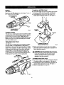
1/2 in., 18 VOLT CORDLESS
Variable Speed / Reversible
DRILL-DRIVER
Model No.
315.113340
Ryobi
Save this manual for
future reference
• Safety
• Features
_k CAUTION:
Read and follow all
Safety Rules and Operating Instructions
before first use of *[his product.
Customer
Help Line: 1-800-932-3188
Sears, Roebuck
and Co., 3333 Beverly Rd., Hoffman
Visit the Craftsman web pago: www.sears.com/craftsman
972000-962
1-02
• Operation
• Maintenance
• Parts List
Estates,
IL 60179
USA
0( 0s
•
Table Of Contents .........................................................................................................................................................
2
• - Warranty .........................................................................................................................................................................
2
•
Introduction .....................................................................................................................................................................
3
•
General Safety RuLes. Specific Safety Rules, And Symbols .....................................................................................
•
Product Specifications ..........................................................
•
Features .....................................................................................................................................................................
•
Operation ..................................................................................................................................................................
•
Maintenance .................................................................................................................................................................
15
•
Accessories ..................................................................................................................................................................
15
•
Exploded View And Repair Parts List ..........................................................................................................................
17
•
Parts Ordedng / Service ...............................................................................................................................................
18
3-6
i .........................................................................................
7
7-8
9-14
FULL ONE YEAR WARRANTY ON CRAFTSMAN 1/2 In. CORDLESS DRILL-DRIVER
If this CRRFTSNRN1/2 in, Cordless DrilFDdver fails to give complete satisfaction within one year from the date of purchase, RETURN IT TO THE NEAREST SEARS STORE OR SEARS SERVICE CENTER IN THE UNITED STATES,
and Sears will repair it, free of charge.
If this CRgFT$14BN1/2 in. CordLessDrill-Driveris used for commercial or rental purposes,this warranty applies for only
90 days from the date of purchase.
This warranty gives you specific legal rights,and you may also have other dghtswhich vary from state to state.
Sears, Roebuck and Co., Dept. 817WA, Hoffmah Estates, IL 60179
A
Look for this symbol to point out important safety precautions. It means attention!!1 Your safety is
involved.
A
WARNING:
The operation of any power tool can resultin foreignobjects being thrown intoyour eyes, which can
result in severe eye damage. Beforebeginning power tool operation,always wear safety goggles or
safety glasses with side shields and a full face shield when needed. We recommend Wide Visib-n
Safety Mask for use over eyeglasses or standard safety glasses with side shields,available at Sears
Retail Stores. Always wear eye protectionwhioh is marked to complywith ANSI Z87.1.
SAFETY AND INTERNATIONAL
SYMBOLS
This operator's manual describes safety and international symbols and piotographs that may appear on this produ_.
Read the operator's manual for complete safety, assemb(y, operating and maintenance, and repair information.
MEANING
Do not expose to rain or use in damp locations.
Your drill-driver has many features for making your drilling
_IL CAUTION: Carefullyread through this entire
operator'smanualbefore using your new drilL-driver.
Pay close attention to the General Safety Rules,
Spedllc Safety Rules and Symbols, Warnings end
Cautions. if you use yourdrill-driverproperlyand only
for it'sintended use, you willenjoy years of safe.
reliable service.
operations more pleasant and enjoyable. Safety,
performanceand dependabilityhave been given top
pdorityin the design of this drill-drivermakingit easy to
maintainand operate.
Personal Safety
_WARNING:
Read and understand ell Instructions.
Failure to follow all instructionslistedbelow, may
result in electric shock,fire and/or seriouspersonal
injury.
•
Stay alert, watch what you ere doing end use
estonian sense when operating a power tool, Do
not use tool while tired or under the influence of
drugs, alcohol, or medication. A moment of inattentionwhile operatingpower tools may resultin serious
personalinjury.
•
Dress properly. Do not wear loose clothing or
jewelry. Contain long hair. Keep your hair, clothing,
end gloves away from moving pads. Looseclothes,
jewelry, or long hair can be caught in moving parts.
Avoid accidental starting. Be sure switch Is In the
locked or off position before inserting battery
pack. Carryingtoolswith yourfinger on the switchor
insertingthe battery pack intoa tool with the switchon,
invitesaccidents.
SAVE THESE INSTRUC'nONS
Work Area
J
Keep your work area clean and well lit. Cluttered
benchesand dark areas inviteaccidents.
•
Do not operate power tools in explosive atmospheres, such as in the presence of flammable
liquids, gases, or dust. Power tools create sparks
whichmay ignite the dust or fumes.
•
Keep bystanders, children, and visitors away while
operating e power tool. Distractionscan cause you
to lose control.
Electrical Safety
•
Do not abuse the cord. Never use the cord to carry
the charger, Keep cord away from heat, oil, sharp
edges, or moving parts. Replace damaged cords
immediately. Damaged cords may create a fire.
•
A battery operated tool with integral batteries or a
separate battery pack must be recharged only with
the specified charger for the battery. A charger that
may be suitable for one type of battery may create a
riskof fire when used with another battery. Use battery
only with charger listed.
MODI=L
BA'rrERY PACK
CHARGER
315.113340
•
•
Item NO. J! 11045
(1323502)
•
.
•
•
Item No. 911041
(1425301 )
Use battery operated tool only with specifically
designated battery pack. Use of any otherbatteries
may create a risk of fire. Use only with battery pack
listed.
3
Remove adjusting keys or wrenches before turnIng the tool on. A wrench or a key that is left attached
to • rotatingpart of the tool may resulfin personal
injury.
Do not overreach. Keep proper footing and balance at all times. Proper footingansibalance enables
better controlof the tool in unexpected situations.Do
not use on a [adderor unstable support.
Use safety equipment. Always wear eye protection.
Dust mask, nonskidsafety shoes, hard hat. or hearing
prOteCtionmust be used for appropriate conditions.
Tool Use and Care
•
Use clamps or other practical way to secure and
support the workplace to a stable platform. Holding
the work by hand or against your body is unstable and
may lead to loss of control
•
Maintain tools with care. Keep cutting tools sharp
and clean. Properly maintained tools, with sharp
cuttingedges are less likelyto bind and are easier to
control.
•
Do not force tool. Use the correct tool for your
application. The correct tool will do the job better and
safer at the rate for which it is designed.
Do not use tool If switch does not turn It on or off.
A tool that cannot be controlled with the switch is
dangerous and must be repaired.
•
Check for mleellgnment or binding of moving parts,
breakage of parts, and any other condition that may
affect the tool's operation. If damaged, have the tool
serviced before using. Many accidents are caused by
poodymaintained tools.
Use only accessories that are recommended by
the manufacturer for your model. Accessoriesthat
may be sult=_blefor one too[,may create a risk of injury
when used on another tool.
•
•
•
•
•
Disconnect battery pack from tool or place the switch
In the locked or off position before maldng any i_lusb
merits, changing acceeeoriss, or stodng the tceL Such
preventive safety measures reduce riskof startingthe tool
acddentaily.
Store idle tools out of reach of children end other
untrained persons. Tools are dangerous in the hands
of unVained users.
Servloe
•
•
When battery pack is not in use, keep it away from
other metal objects like: paper clips, coins, keys,
nails, screws, or other small metal objects that can
make a connection from one terminal to another.
Shodthg the battery terminals together may cause
sparks, burns, or a fire.
Tool service must be performed only by qua,fled
repair personnel. Service or maintenance performed
by unqualifiedpersonnelcould result in a risk of injury.
When servicing a tool, use only identical replacement parts. Follow instructions tn the Maintenance
section of this manual. Usa of unauthorizedparts or
failure to follow Maintenanco Instructionsmay create a
risk of shock or injury.
Hold tool by Insulated gripping surfaces when performing an operation where the cutting tool may contact
wiring. Contact with a "live" wire will make exposed metal parts of the tool "live" and shock the opera,or.
Additional
•
•
Rules
For Safe
fire or heat. This will reducethe risk of explosionand
possibleinjury.
Operation
Know your power fool. Read operator's manual
carefully. Learn its applications and limitations, as
well as the specific putentlal hazards related to
this tool. Following this rule will reduce the risk of
electric shock, fire, or serious injury.
A
Make sure your extension cord is in good condition.
When using an extension cord, be sure to use one
heavy enough to carry the current your product will
draw. A wire gage size (A.W.G.) of at leaSt 16 is
recommended for an extension cord 100 feet or less
in length. A cord exceeding 100 feet Is not recommended, If In doubt, use the next heavier gage. The
smaller the gage number, the heavier the cord° An
undersized cord will cause a drop in lii_evoltage resulting in loss of power and overheating.
Important
Rules
for Battery
Battery tools do not have to be plugged into an
electrical outlet; therefore, they are always In
operating condition. Be aware of possible hazards
when not using your battery tool or when changIng accessories.
FoJ]owing this rule will reduce the
risk of electric shock, fire, or serious personal iniury.
•
De nat place battery tools or their batteries
WARNING:
Batteries vent hydrogen gas alld can
explode in the presence of a source of ignition, such
as a pilot light. To reduce the risk of serious personal
injury, never use any cordless product in the presence of open flame. An exploded battery can propel
debris and chemicals. If exposed, flush with water
immediately.
Do not charge battery tool in a damp or wet
location. Following this rule will reducs the risk of
electric shock.
For best results, your battery tool should be
charged in a location where the temperature is
more than 50°F but less than 100°F. Do not store
outside or in vehicles.
Tools
•
hidden
Under extreme usage or temperature conditions,
battery leakage may occur. If liquid comes In
contact with your skin, wash Immediately with
soap and water, then neutralize with lemon juice
or vinegar, If liquid gets into your eyes, flush them
with clean water for at least 10 minutes, then seek
immediate medical attention. Following this rule will
reduce the risk of serious personal injury.
near
4
,_WARNING:
Never use a battery that has been
dropped or received a sharp blow. A damaged battery
is subjectto explosion. Properly dispose of a dropped
battery immediately. Failure to heed this warningcan
result in serious personal injury.
•
Save these instructions. This manual €ontains
Important safety and Operetlng Instructions for
charger. Following this rule will reduce the dsk of
electric shock, fire, or serious personal injury,
•
Before using battery charger, read ell instructions
and cautionary markings In this manual, on
battery charger, and product using battery
charger. Followingthis rule will reduce the risk of
electric shock, fire. or serious personal injury.
ACAUTION:
To reduce risk of injury, charge only
nickel-cadmium
and nickel metal hydride type
rechergeeble batteries. Other types of batteries
may burst causing personal injury end damage.
Following this rule will reduce the risk of electric
shock, fire, or serious personal injury
•
DO nat operate charger with a damaged cord or
plug. If damaged, have replaced Immediately by a
qualified servioegl_n. Following this ru[e will reduce the
risk of electric shock, fire, or serious personal injury.
'•
Do not operate charger If It has received a sharp
blow_ been dropped, or otherwise damaged In any
way; take it to a qualified serviceman. Following
this ru[e will reduce the risk of electric shock, fire, or
serious personal injury.
•
Do not disassemble charger; take it to a qualified
servicemen when service or repair Is required.
Incorrect reassembly may result In s risk of
electric shock or fire. Following this rule will reduce
the risk of electric shock, fire, or serious personal
injury.
•
To reduce the risk of electric shook, unplug
charger from outlet before _'temptlng
any maintahence or €lesnlng. Turning off controls will not
reduce this risk. Following this rule will reduce the
risk of electric shock, fire, or serious personal injury.
•
Do not expose charger to rein or snow. Following
this rule will reduce the risk of eleck'ic shock, fire, or
serious personal injury.
•
Do not use charger outdoors, Following this rule will
reduce the risk of elect_c shock, fire, or serious
personal injury.
•
Use of an attachment not recommended or sold
by the battery charger manufacturer may result In
a risk of fire, electric shock, or injury to persons.
Following this rule will reduce the risk of electric
shock, fire, or serious personal [njury.
•
Disconnect charger from power supply when not
In use. Following this rule will reduce the risk of
electric shock, fire, or serious personal injury.
•
•
•
To reduce risk of damage to charger body end
cord, pull by charger plug rather than cord when
disconnecting
charger. Following this rule will
reduce the risk of electric shock, fire, or serious
personal injury
Make sure cord Is located so that it will not be
stepped on, tripped ever, or otherwise subjected
to damage or stress. FoUowing this rule will reduce
the risk of serious personal injury.
An extension cord should not be used unless
absolutely
necessary.
Use of improper extension
cord could result in a risk of fire and electric shock. If
extension cord must be used, make sure:
b, That extension cord is properly wired and in
good electrical condition; and
c That wire size is large enough for AC ampere
rating of charger as specified below:
25'
50'
100'
Cord Size (AWG)
16
16
16
DANGER: RISK OF ELECTRIC SHOCK. DO NOT
TOUCH UNINSULATED PORTION OF OUTPUT
CONNECTOR OR UNINSULATED BATrERY
TERMINAL•
•
Save these instructions. Refer to them frequently
and use them to instruct others who may use this
tool. If you loan someone this tool, loan them
these instructions also. Followingthis rule will
reduce the risk of electric shock, fire, or serious
personal injury.
_LWARNING:
Some dust created by power sanding,
sawing, grinding, drilling, and other construction
activities contains chemicals known to cause
cancer, birth detects or other reproductive harm.
Some examples of these chemicals are:
• lead from lead-based paints,
• crystalline silica from bricks and cement
and other masonry products, and
• arsenic and chromium from chemicallytreated lumber.
Your risk from these exposures varies, depending
on how often you do this type of work. To reduce
your exposure to these chemicals: work in a well
ventilated ares, and work with approved safety
equipment, such as those dust masks that are
specially designed to filter out microscopic particles.
a. That pins on plug of extension cord are the
same number, size and shape as those of
plug on charger,
Cord Length (Feet)
A
Note: AWG = American Wire Gage
SAVE THESE INSTRUCTIONS
5
m
m
.Important: Some of the followingsymbolsmay be used on yourtool. Please studythem and learn their meaning.Proper
interpretationof these symbolswill allow you to operate the tool better and safer.
SYMBOL
NAME
DESIGNATION/EXP LANATION
V
Volts
Voltage
A
Amperes
Current
Hz
Hertz
Frequency (cycles per second)
rain
Minutes
Time
AlternatingCurrent
Type or a characteristicof current
m
m
Direct Current
Type or a characteristicof current
no
NO Load Speed
Rotationalspeed, at no load
../min
Revolutionsor Reciprocation Per Minute
Revolutions,strokes,
surface speed, orbitsetc. per minute
Safety Alert Symbol
Indicatesdanger, warning or caution.
It means attention!!!Your safety is
involved.
==J=
The purpose of safety symbols is to attract your attention to possible dangers. The safety symbols, and
the explanations with them, deserve your careful attention and understanding. The safety warnings do
not by themselves eliminate any danger. The Instructions or warnings they give are not substitutes for
proper accident prevention measures.
SYMBOL
MEANING
SAFETY ALERT SYMBOL:
indicatesdanger, warning,or caution.May be used in conjunctionwithothersymbolsor pictographs.-
A
A
,a,
NOTE:
DANGER; Failureto obey a safety warningwillresult in serious injuryto yourself or to others.
Always follow the safety precautionsto reducethe risk of fire, electricshock and personalinjury.
WARNING: Failure to obey a safety warningcan result in serious injuryto yourselfor to others.
Always followthe safety precautionsto reducethe risk of fire, electricshock and personalinjury.
CAUTION: Failure to obey a safety warningmay result in propertydamage or personal injuryto
yourself or to others.Always follow the safety precautionsto reducethe risk of fire, electricshock
and personal injury.
Advises you of informationor instructionsvital to the operation or maintenanceof the equipment.
6
DRILL-DRIVER
Chuck
Motor
315.113340
1/2in.Keytess
DCMotor18Volt
Gear Train
Two Speed
No Load Speed
0-350 RPM (Low)
0-1300 RPM (High)
Clutch
24 Positions
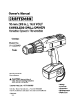
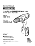
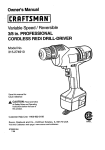
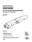
KNOW YOUR DRILL-DRIVER
See Figure f.
Before attempting to use yourdrill-driver,familiarize
yourself with all operating features and safety
requirements.
KEYLESS CHUCK
Maximum Torque
400 in./Ibs
CHARGER
Item No. 9 11041
(1425301)
Rating
120 V, 60 Hz, AC only
Charging Voltage
7.2 - 24 Volt
Charge Rate
1 Hour
BAI-rERY
Item No. 9 11045
(1323502)
PACK
FORWARD/REVERSE
SELECTOR
(DIRECTION OF ROTATION SELECTOR)
Your drill-driverhas a forward/reverseselector located
above the switchtrigger.
WRIST STRAP
Your dri[I-driverhas a keylass chuckthat allowsyou to hand
tightenor release drillbit in the chuck:jaws.
A wrist strap is providedto reduce the chances of
droppingyourdrill-driver.Place one hand throughthe wrist
strap when carryingtool.
SWITCH
BIT STORAGE
To turn your drill-driverON, depress the switch '0"igger.
Release switch triggerto turnyour drill-dryer OFF.
When not in use, bits provided with your drill-drivercan be
placed in the storage area located on the bottomof the
motor housing.
SWITCH LOCK
The switchtrigger can be locked in the OFF position.This
feature helps reduce the possibilityof-accidentalstarting
when not in usa.
VARIABLE
SPEED
This tool has a variable speed switch that delivers higher
speed with increased trigger pressure, Speed is controlled
by the amount of switch trigger depression,
"I'WO SPEED GEAR TRAIN
Your drill-driverhas a two speed gear train designedfor
drilling or driving at HI or LO speeds, A slide switchis
locatedon top of your ddll to select either HI or LO speed.
LEVEL
To keep drillbit level during drillingoperations, a level is
• Jocated on the top and end of the motorhousing.
A
WARNING: If any parts are missing,do not operate
yourdrill-driveruntilthe missingpars are replaced.
Failureto do socould resultin possibleserious
personalinjury.
TWO-SPEED
GEAR TRAIN (HI-LO)
KEYLESS
CHUCK
LEVEL
TORQUE
ADJUSTMENT
RING
REAR VIEW
DIRECTION
OF
ROTATION
SELECTOR
(FORWARD/REVERSE)
B_
STORAGE
SCREWDRIVER
BATTERYPACK
SHOWNINTOOL
BATTERY PACK
SHOWNINCHARGER
4-1/2in.
WRIST STRAP
CHARGER
RED LED ONIN_CATES
MOD£
GREENLED ON AFTER FAST CHARGING
CYCLE,INDICATESFULLYCHARGEDBATTERY
PACK AND IN TRICKLECHARGE MODE.
YELLOWAND GREENLEDSON INDICATESDEEPLY
DISCHARGEDOR DEFECTIVEBATTERYPACK.
Fig. 1
CHARGER
Bee _'@ufe f,
Your charger has a "key ho[e" hanging feature for convenient, space saving storage. Screws should be installed
center distances are 4-1/2 inches apart.
B
so that
_
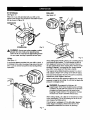
LED FUNCTIONS OF CHARGER
LED WILL BE ON TO INDICATE STATUS OF
CHARGER AND BATrERY PACK:
WARNING: DOnot allow familiaritywith yourdrilldriver to make you careless. Remember that a
careless fraction of a second is sufficientto inflict
severe injury,
BA'I'rERY
PACK
The battery packfor your tool has been shippedin a low
charge conditionto prevent possibleproblems.Therefore,
you shouldcharge it until light on front ofcharger changes
from redto green.
Note; Batterieswill not reach full charge the firsttime they
are charged. Allow several cycles (drillingfollowedby
recharging}for them to become fully charged.
CHARGING BA'I-I'ERY PACK
See F/gum [
•
Charge battery pack only with the charger provided.
•
Make sure power supply is normal household
voltage, 120 volts, 60 Ha, AC only,
•
•
Connect charger to power supply.
Place battery pack in charger aligning raisedrib on
battery packwith groove in charger, See Figure.1.
Press down on battery pack to be sure €ont=qcts
on
battery pack engage properly with contacts in charger,
Normally,the red LED on charger willcome on. This
indicatescharger is in fast charging mode.
Red LED should remain on for approximately1 hour
then the green LED will come on. Green LED on
indicatesbattery pack is fully charged and charger is in
trickle charge mode. Note: Green LED will remainon
untilbattery pack is removed from charger or charger
is disconnectedfrom power supply,
•
•
•
•
•
The battery pack will become slightlywarm to the
touch while Charging.This is normal and does not
indicate a problem.
Do not place charger and battery pack in alt area of
extreme heat or cold. It will work best at normal room
temperature.
•
•
Green LED on = When battery pack is inserted into
charger, indicateshot battery pack or that battery pack
is out of or below norms[temperature range.
Yellow and Green LEDs on = Deeply dischargedor
defectivebe,ttery pack,
No LED on = Defective charger or battery pack.
_1, CAUTION: To prevent damage to battery pack,
remove battery pack from charger immediately if no
LED comes on. Return battery pack and charger to
your nearest Sears Service Center for checking or
replacing,Also, if you ere removingbattery pack from
charger and no LEDs are on, return both battery pack
and charger to your nearest Sears Service Center.
Do not insert another battery pack intocharger. A
damaged charger may damage a battery pack.
IMPORTANT INFORMATION
HOT !BA'I'FERY PACK
FOR RECHARGING
When using your drill-drivercontinuously,the batteries in
your battery pack will become hot. You shouldlet a hot
battery pack cooldown for approximately 30 minutes
before attempting to recharge. When the battery pack
becomes dischargedand is hot, this will cause the green
"LEDto come on instead of the red LED. After 30 minutes,
reinsert battery pack in charger, If green LED continuesto
remain on, return battery pack to your nearest Sears
Repair Center for checking or replacing.
Note: This situationonlyoccurs when continuoususe of
your drill causes the batteries to become hot. it does not
occurunder normal circumstances.Refer to "CHARGING
BATrERY PACK" for normal rechargingof batteries, If
the charger does not charge yourbattery pack under
normal circumstances,return both the battery pack and
charger to your nearest Sears Repair Center for electrical
check.
IMPORTANT INFORMATION
COOL BATTERY PACK
FOR RECHARGING
If battery pack Is below normal temperature range, the
green LED on charger will come on. Allow battery pack to
reach normal temperature,then the red LED will come on,
Note: Refer to "CHARGING BATrERY PACK" for
normal rechargingof batteries. If the charger does not
charge your battery pack under normal circumstances,
return both the battery pack and charger to your nearest
Sears Repair Center for electrical check.
Note: Charger and battery pack should be placed in a
locationwhere the temperature Is more than 50°F but
less than 100°F.
•
Green LED on = Fu[lycharged and in tricklecharge
mode_
•
Allow baffery pack to remain in charger for 15 to 30
minutes. When battery pack reaches normal voltage
range, red LED should come on.
If red LED does not come on after 30 minutes,this
indicates a defective battery pack and should be
replaced.
After normal usage, a minimum of 1 hour of charging
time is required to fully recharge battery pack.
Red LED on = Fast chargingmode.
1
•
if bothyellow and green LED come on, this indicates a
deeplydischarged or detective battery pack.
•
•
When batteries become fully charged, unplugcharger
from power supply and remove the battery pack.
9
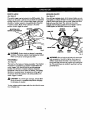
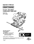
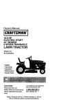
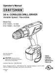
SWITCH
TO INSTALL BA'I-rERY PACK
,Fee Figure 2.
To turn your drill ON, depress the switch trigger. To turn it
OFF, release the switch trigger.
•
Lock switch triggeron your drillby placingthe direction
of rotationselectorin center position. See F/#uFe5.
•
Place battery pack in yourdrill, Align raised rib on
battery pack with groove inside drll{, See F3_'Ure4.
FORWARD/REVERSE
SELECTOR
VARIABLESPEED
SWITCHTRIGGER
Fig. 2
VARIABLESPEED
LATCHES
This tool has a variable speed switch that delivers higher
speed and torque with increased triggerpressure.Speed is
controlledby the amount o! switch triggerdepression.
Note: You might hear a whistling or ringingnoisefrom the
switch during use, Do not be concerned, this is a normal
part of the switch function.
TWO-SPEED
See Figure3.
GEAR TRAIN
DEPRESSLATCHESTC
RELEASE EATrERYPACK
Your drill has a two-speed gear train designed for drilling
or drivingat LO (1) or HI (2) speeds. A sllde switchis
locatedon top of your drillto select either LO (1) or HI (2)
speed. When using drillin the LO (1) speed range, speed
will decrease and unit will here mere power and torque.
When using drill in the HI (2) speed range, speed will
increase and unit will have lens power and torque. Use
LO (1) speed for high power and torque applications and
HI (2) speed !or fast drillingor driving applications.
TWOSPEED
GEARTRAIN(HFLO)
•
_
LO
SPEED
Fig 4
Make sure the latches on each side of your battery
pack snap in place and battery pack is secured in drill
before beginning operation.
CAUTION: When placingbattery pack Jnyour drill,
be sure raised ribon battery pack aligns with groove
inside drilland latches snap intoplace properly.
Improper assembly of battery pack can cause
damage to internalcomponents.
TO REMOVE BATTERY PACK
II Lock switch triggeron your ddll by placingthe direction
of rotationselectorin center position. Sea Figure 5.
• Locate latches on side of battery pack and depress to
release battery pack from your drill See F/qure 4.
• Remove bat'[erypack from your drill.
HI
SPEED
10
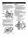
SWITCHLOCK
KEYLESS CHUCK
See Figure S.
See Fi#ure 6.
The switch trigger can be locked in the OFF position.This
feature can be used to prevent the possibilityof accidental
starting when not in use. To lookswitch trigger, place the
direction of rotation selector (ForWard/ReverseSelector)
in center position.Note: When selector is in centar
position,switch trigger is locked,
SELECTOR WITH
CENTER LOCK POSITION
REVERSE
DRILLsn"
f
FORWARD
A
Your drillh_ a keylesschuck.ASthe name implies,you can
handtightenor release ddllbitsin the chuckjaws, Grasp and
holdthe collarofthe chuckwith one hand. Rotatethe chuck
"body withyourotherhand. The an'oweon the chuck
indicatewhichdirectionto rotatethe chuckboclyin orderto
LOCK (t_ghten)or UNLOCK (release) the drillbit,
. SWITCH
TRIGGER
Fig. 5
CHUCK
COLLAR
CHUCKJAWS
LOCK
(_GHTEH)
WARNING:
Battery tools are always in operating
condition. Therefore, switch should always be locked
when not in use or carrying at your side.
CHUCK
BODY
Fig. 6
_
REVERSIBLE
See F_gum
This tool has the feature of being reversible. The direction •
of rotation is controlledby a selector located above the
switchtrigger. With the drill held in normal operating
position,the direction of rotation selector shouldbe
positionedto the left of the switch for drilling.The drilling
direction is reversed when the selector is to the right of
the switch, When the selector is in center position,the
switch trigger is locked.
_l,
UNLOCK
(RELEASE)
CAUTION:
To prevent gear damage, always allow
chuck to come to a complete stop before changing
the direction of rotation.
To stop, release switch trigger and allow the chuckto come
to a complete stop.
11
WARNING:
Do not hold chuck body with one hand
and use power of the drill to tighten chuck jaws on
drill bit. Chuck body could slip in your hand or your
hand could slip and come in contact with rotatingdrill
bit. This could cause an accident resulting in serious
personalinjuPf.
INSTALLING BITS
See Figure 7.
REMOVING BITS
B
Lookthe switch trigger by placing the directionof
rotationselector in center position.See F_um 5,
•
•
Open or close chuck jaws to a point where the opening is slightlylarger than the bit size you intendto use.
Also, raise the front of your drillslightlyto keep the bit
from falling out of the chuck jaws.
•
•
•
See Fi#ure 7.
•
Insert drillbit straight into chuck the full length of the
jaws as shown in Figure 7.
Tighten the chuck jaws on drillbit.
DRILL BIT
UNLOCK
(RELEASE)
•
•
CHUCK
COLLAR
Lockthe switchtdgger by placingthe direction of
rotationselector in center position.See Figure 5.
Loosen the chuckjaws from drill bit.
To loosen:grasp and hold the collar of the chuckwith
one hand, while rotatingchuck body with your other
hand. Note: Rotate chuck body in the directionof the
arrow marked UNLOCK to loosen chuckjaws.
Do not use a wrench to tighten or loosen the chuck
jaws.
Remove drillbit from chuck jaws.
ADJUSTABLE
TORQUE CLUTCH
Your drill is equipped with en adjustable torque clutch for
driving different types of screws into different materials.
The proper seffing depends on the type of materhd and the
size of screw you are using.
TO ADJUST TORQUE
Identifythe twentyfourtorque indicatorsettingslocated
on the front of your drill. See Figure9,
Rotate adjustingring to the desired setting.
• 1- 4
For drivingsmall screws.
CHUCKJAW$
LOCK
(TIGHTEN)
RIGHT
•
•
5-8
CHUCK
BODY
• 9 - 12
- 13 - 16
For driving screws intosoft and herd
materials.
For drivingscrews in hard wood.
• 17 - 20
For driving large screws.
• 21 - 411
For heavy drilling.
Fig. 7
TOtighten the chuck jaws on drill bit;grasp and hold
the collar of the chuck with one hand, while rotating
the chuck body with your other hand.
Note: Rotate the chuck body in the directionof the
arrow marked LOCK to t_ghfenchuckjaws.
Do not use a wrench to tighten or loosen the chuck
jaws.
For drivingscrews intosoft
material.
TODECREASE
TOROUE
ADJUSTING
RING
WARNING:
Make sure to insert drill bit straight into
chuck jaws. Do not insert drill bR into chuck jaws at
an angle then tighten, as shown in Figure 8. This
could cause dri[I bit to be thrown from ddll, resulting
in possible serious personal injury or damage to the
chuck.
TO INCREASE
TORQUE
Fig. 8
12
Fig. 9
BIT STORAGE
Bee Figure 10.
When not in use, bits provided with your drillcan be
placed in the storage area located on the bottomof your
drill as shown in Figure 10.
LEVEL
SCREWDRIVER
BIT
B!
STORAGEAREA
,_,
Fig. I0
WARNING: Always wear safety gogglesor safety
glasses with side shieldswhen operating t_ols.
Failureto do Socould resultin objectsbeing thrown
intoyour eyes, resultingin possibleserious injury.
Fig. 12
LEVEL
See Figure77.
A convenient feature provided with your drillis a level. It
is recessed in the motor housing on top and end of your
drill. Itcan be used to keep drillbit level duringdrilling
operations.
When ddlling hard smoothsurfaces use a center punch to
mark desired hole location.This will prevent the drillhit
• .from slippingoff center as the hole is started. However,
the low speed feature allows starting holeswithout center
punchingif desired. To accomplishthis. simply operate
your ddll at a low speed until the hole is started.
The materialto be drilled should be secured in a vise or
with clamps to keep it from turning as the drillbit rotates.
Hold tool firmly and place the bit at the point to be drilled.
Depress the switch trigger to starttool.
Move the drillbit intothe workpiece applyingonly enough
pressure to keep the bit cutting.Do not force or apply side
pressure to elongate a ho]e.
A
WARNING:
Be prepared for binding or bit
breakthrough. When these situations occur, drill has
a tendency to grab and kick opposite to the direction
of rotation and could cause loss of control when
breaking through material. It not prepared, this loss
of control can result in possible sedous injury.
When drilling metals, use a light oli on the drill bit to keep
it from overheating.The oil willprolongthe Jifeof the bit
and increase the drillingaction.
If the bit jams in workpiece or if the drillstalls, release
switch trigger immediately. Remove the bitfrom the
work.pieceand determine the reason for jamming.
Fig. 1 1
13
CHUCK
•
REMOVAL
See Figures 13, 1#, and 15.
The chuck must be removed in order to use some
accessories. To remove:
•
Lock the switch trigger by placing the direction of
rotation seJector in center position. See FTgure ..5..
•
Insert a 5/16 in. or larger hex key into the chuck of your
dnn and tighten the chuck jaws securely.
•
Tap the hex key sharply with a mallet in a clockwise
direction. See Figure 13. This wgl loosen the screw in
the chuck for easy removal.
Insert hex key in chuck and tighten chuck jaws securely. Tap sharply with e mallet in a counterclockwise
direction. This will loosen chuck on the spindle. It can
now be unscrewed by hand. See Figure f_
MALLET
•ALLET
CHUCKJAW$
Fig. 15
TO RETIGHTEN
A LOOSE
CHUCK
The chuck may become loose on spindle and develop a
wobble. Periodically check chuck screw for tightness,
REXKEY
•
KEYLESS
CHUCK
To tighten, follow these steps:
Fig. 13
Open chuck jaws and remove hex key. Remove the
chuck screw by turning it in e clockwisedirection. ,5'ee
FigureI_[
Note: The screw has left hand threads,
II Lock the switch tdgger by placing the direction of
rotation selector in center position. See Figure 5
. .11 Open the chuck jaws.
SCREWDRIVER
•
Insert hex key into chuck and tighten chuck jaws
securely. Tap hex key sharply with a maUet in a
clockwise direction. This will tighten chuck on the
spindle.
•
Open the chuck jaws and remove hex key.
•
Tighten the chuck screw.
Note: The chuck screw has left hand threads.
14
Do not abuse power tools. Abusive prances
damage tool as well as workplace.
WARNING: When servicing, use only Identical
Craftsman replacement parts. Use of any other
part may create a hazard or cause productdamage.
Only the parts shown on parts list. page 17, are intended
to be repaired or replaced by the customer. All other parts
should be replaced at a Sears Service Center,
Avoid using solvents when cleaning pJastic parts. Most
plastics are susceptible to damage from various types of
commercial solvents and may be damaged by their usa.
Use clean cloths to remove dirt, dust, eli, grease, etc.
A
can
_
WARNING:
Do not at any time let brake fluids,
gasoline, petroleum-based products, penetrating oils,
etc. come in contact with plastic parts. They contain
chemicals that can damage, weaken or destroy
plastic.
WARNING: Do not attempt to modify this tool or
create accessories not recommended for use with
this tool Any such alteration or modificationis
misuse and could result in a hazardous condition
leadingto possibleserious personal injury.
BATTERIES
Your drill's battery pack is equipped with nickel-cadmium
rechargeable batteries. Length of service from each
charging will depend on the type of work you are doing.
•
The batteries in this tool have been designed to provide
maximum trouble free life. However, like all batteries, they
will eventually wear out. Do not disassemble battery pack
and attempt to replace the batteries. Handling of these
batteries, especially when wearing rings and jewelry,
could result in a serious bum.
•
•
To obtain the Jongest possible battery life, we suggest the
following:
Store and charge your batteries in a cool area.
Temperatures above or below norma[room
temperature will shortenbattery life.
Never store batteriesin a discharged condition.
Recharge them immediately after they are
discharged,
All batteriesgradually lose their char'ge.The higher
the temperature the quicker they lose their charge, if
you store yourtool for long periodsof time without
using it, recharge the batteries every month or two.
This practicewill prolong battery life.
• BATTERY PACK REMOVAL AND PREPARATION
To preservenaturalresources, please
recycleor disposeof batteriesproperly.
FOR RECYCLING
This product contains nickel-cadmium
batteries. Local, state or federal laws
WARNING:
Upon removal, cover the battery pack's
may prohibitdisposal of nickel-cadmium
terminals with heavy duty adhesive tape. De not
batteries in ordinarytrash.
attempt to destroy or disassemble battery pack or
remove any of ifs components. Nickel-cadmium
Consult your local waste authorityfor information
batteries must be recycled or disposed of propody.
regardingavailable recyclingand/or disposaloptions.
A
Also. never touch both terminals with metal objects
and/or body parts as short circuit may result. Keep
away from children. Failure to comply with these
warnings could result in fire and/or serious injury.
The following recommended
accessories are currently available at Sears Retail Stores.
•
6-Pc. Extra Length Magnite Power Bit Set
•
High Speed Bits......t/2
•
30-Pc. Power Screwdriver/Nutdriver
Set and Case
•
Wood Boring Bits.....t-1/2
•
17-Pc. Power Screwdr'iver/Nutdriver
Set and Case
_
WARNING:
The use of attachments or accessories not listed might be hazardous.
15
in. Max.
in. Max.
i
I
I
I
I
II
16
.
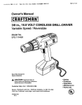
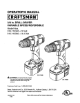
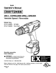
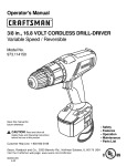
CRAFTSMAN
1/2 In., 18 VOLT
CORDLESS
DRILL-DRIVER
- MODEL
NO. 315.113340
in all correspondence regarding your 1/2 in., 18 VOLT CORDLESS DRILL-DRIVER or when ordering repair
The
parts.model number will be found on a plate attached to the motor housing. Always mention the model number
SEE BACK
PAGE
FOR
PARTS
ORDERING
I
|
INSTRUCTIONS
2
4
3
PARTS LIST
Key
No.
Pert
Number
1
975379-000
Screw (Special) ......................................................................
1
2
6903323
Chuck .....................................................................................
1
1
Description
Ouan.
3
"Item No. 9 11045
Battery Pack (1323502)
4
*Item No._
Charger (1425301) .................................................................
!
5
3064302
Carrying Case - Not Shown ..................................................
1
972000-962
Operator's
11041
.........................................................
Manual
* Can Be Purchased Thru RSOS (Retail Special Order System)
b,
J
17
G:et it
at,
ur
, ,,,
For repair of major brand appliarlces in your own home...
no matter who made it, no matter who sold it!
1-800-4-MY-HOM
E sMAnytime,
dayornight
(1-800469.-4663)
WW_N.seRrs.COITI
To bring in products such as vacuums, lawn equipment and electronics
for repair, call for the location of your nearest Sears Parts & Repair Center.
1-800-488-1222
Anytime, dayor
night
www.sears.com
For the replacement parts, accessories and owner's manuals
that you need to do-it-yourself, call Sears PartsDirect sM!
1-800-366-PART
6am- 11pm CST
(1-800-366-7278).
7 days a week
www.sears.com/partsdirect
To purchase or inquire about a Sears Service Agreement:
1-800-827-6655
7 a.m. - 5 p.m. CST, Mon. - Sat.
Para pedir servicio de reparacibn a domicilio,
y para ordenar plazas con entrega a domicilio:
1-888-SU-HOGAR
_
Au Canada pour service en franr.,ais:
1-877-LE-FOYER ='
(1-877-533q5937)
(1-888-784-6427)
HomeCentrar
_ Rv'_i_4e red Trademark
© Sears,
Roebuck
and C,Q.
® Mama
Reglsb=0e
I
TM
/
J
"J'radernirk of Sean_, Roebuck
Ma_.al _e F_lbriCa dc _1_,
and Co.
ROebUCk and CO.