1
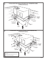
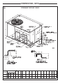
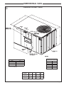
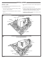
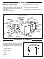
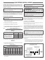
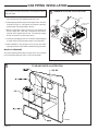
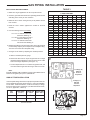
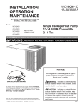
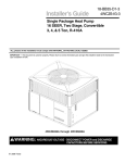
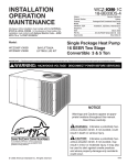
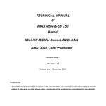
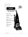
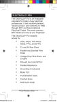
INSTALLATION
OPERATION
MAINTENANCE
ALL phases of this installation must comply with
NATIONAL, STATE AND LOCAL CODES
Model:
YCZ036F1/3M0B
YCZ060F1/3M0B
BAYLIFT002A
LIFTING LUG KIT
YCZ-IOM-1A
18-EB21D4-2
Library
Product Section
Product
Model
Literature Type
Sequence
Date
File No.
Supercedes
Service Literature
Unitary
Packaged Gas/Electric
YCZ
Installation, Operation, Maintenance
1A
July 1999
SV-UN-RT-YCZ-IOM-1A 7/99
YCZ-IOM-1
Single Package Two Stage
Gas/Electric 16 SEER
Convertible 3 & 5 Ton
IMPORTANT — This Document is customer property and is to remain with this unit. Please return to service information pack upon completion of work.
WARNING: HAZARDOUS VOLTAGE - DISCONNECT POWER BEFORE SERVICING
All phases of this installation must comply with the NATIONAL, STATE & LOCAL CODES. In the absence of local codes, the
installation must conform with National Electric Code -- ANSI/NFPA 70 or "LATEST REVISION."
Since the manufacturer has a policy of continuous
product improvement, it reserves the right to change
specifications and design without notice.
© American Standard Inc. 1999
GENERAL INFORMATION
IMPORTANT: Read this entire manual before beginning
installation procedures.
▲WARNING:
BODILY INJURY CAN RESULT FROM
HIGH VOLTAGE ELECTRICAL COMPONENTS, FAST MOVING FANS,
AND COMBUSTIBLE GAS. FOR PROTECTION FROM THESE
INHERENT HAZARDS DURING INSTALLATION AND SERVICING,
THE ELECTRICAL SUPPLY MUST BE DISCONNECTED AND THE
MAIN GAS VALVE MUST BE TURNED OFF. IF OPERATING CHECKS
MUST BE PERFORMED WITH THE UNIT OPERATING, IT IS THE
TECHNICIANS RESPONSIBILTY TO RECOGNIZE THESE HAZARDS
AND PROCEED SAFELY.
IMPORTANT: DO NOT CONNECT GAS PIPING TO THE UNIT
UNTIL A LINE PRESSURE TEST HAS BEEN COMPLETED.
DAMAGE TO THE GAS VALVE MAY RESULT IN AN UNSAFE
CONDITION. THIS UNIT SHOULD NEVER BE EXPOSED TO
GAS LINE PRESSURE IN EXCESS OF 14 INCHES WATER
COLUMN. (1/2 PSIG)
IMPORTANT: RECONNECT ALL GROUNDING DEVICES.
ALL PARTS OF THIS PRODUCT CAPABLE OF CONDUCTING
ELECTRICAL CURRENT ARE GROUNDED. IF GROUNDING
WIRES, SCREWS, STRAPS, CLIPS NUTS OR WASHERS
USED TO COMPLETE A PATH TO GROUND ARE REMOVED
FOR SERVICE, THEY MUST BE RETURNED TO THEIR ORIGINAL POSITION AND PROPERLY FASTENED.
IMPORTANT: ALL POWER LEGS MAY NOT BE BROKEN BY
CONTACTORS. SEE WIRING DIAGRAM ON UNIT CONTROL
BOX COVER.
THIS UNIT, AS SHIPPED FROM THE FACTORY, IS DESIGNED FOR NATURAL GAS ONLY.
BEFORE STARTING THE COMPRESSOR, THE CRANKCASE
HEATER SHOULD BE ENERGIZED FOR EIGHT HOURS
Read this manual carefully before attempting to install, operate, or
perform maintenance on this unit. Installation and maintenance
should be performed by qualified service technicians only.
NOTE: “Warnings” and “Cautions” appear at appropriate
places in this manual. Your personal safety and the proper
operation of this air conditioning product require that you follow
them carefully. The manufacturer assumes no liability for
installations or servicing performed by unqualified personnel.
INSPECTION
1. Check for damage after the unit is unloaded. Report promptly, to
the carrier, any damage found to the unit. Do not drop the unit.
IMPORTANT: The use of “spreader bars” is required when
hoisting the unit (to prevent damage to sides and top).
2. Check the unit’s nameplate to determine if the unit is correct for
the intended application. The power supply must be adequate for
both the unit and all accessories.
3. Check to be sure the refrigerant charge has been retained during
shipment. Access to 1/4" flare pressure taps may be gained by
removing the furnace compartment access panel.
The following warning complies with State of California law, Proposition 65.
▲WARNING:
Hazardous Gasses!
Exposure to fuel substances or by-products of incomplete
fuel combustion is believed by the state of California to
cause cancer, birth defects, or other reproductive harm.
The following warning complies with State of California law, Proposition 65.
▲WARNING:
This product contains
fiberglass wool insulation! Fiberglass dust and ceramic
fibers are believed by the State of California to cause
cancer through inhalation. Glasswool fibers may also
cause respiratory, skin, or eye irritation.
PRECAUTIONARY MEASURES
●
Avoid breathing fiberglass dust.
●
Use a NIOSH approved dust/mist respirator.
●
Avoid contact with the skin or eyes. Wear longsleeved, loose-fitting clothing, gloves, and eye
protection.
●
Wash clothes separately from other clothing: rinse
washer thoroughly.
●
Operations such as sawing, blowing, tear-out, and
spraying may generate fiber concentrations requiring
additional respiratory protection. Use the appropriate
NIOSH approved respirator in these situations.
As shipped from the factory, this unit is for use with natural gas only,
and is listed by Underwriters Laboratory.
Model YCZ heating/cooling units are designed for outdoor mounting with a vertical condenser discharge. They can be located either
at ground level or on a roof, in accordance with local codes or
National Fuel Gas Code (ANSI-Z223.1A) Latest Revision. Since
these units are designed exclusively for outdoor operation, additional flue venting systems are not required. Each unit contains an
operating charge of Refrigerant-22 as shipped.
FIRST AID MEASURES
Eye Contact
WARNING: HAZARDOUS VOLTAGE - DISCONNECT POWER BEFORE SERVICING
Page 2
-
Flush eyes with water to remove dust.
If symptoms persist, seek medical
attention.
Skin Contact -
Wash affected areas gently with soap
and warm water after handling.
➀
TYPICAL ROOFTOP INSTALLATION WITH FULL PERIMETER CURBS
(YCZ036,060F Models)
FIELD SUPPLIED
SUPPORTS
AT EACH END
OF CURB
ROOFING
ROOF INSULATION
FIELD SUPPLIED
CANT STRIP
ROOF DECK
FIELD SUPPLIED
RIGID INSULATION
ROOF MOUNTING
CURB
SUPPLY AIR
DUCT
➁
RETURN AIR
DUCT
TYPICAL ROOFTOP INSTALLATION WITH BAYCURB030A,038A
(YCZ036,060F Models)
SEE NOTE 1
SEE NOTE 2
FIELD SUPPLIED
SUPPORTS
AT EACH END
OF CURB
ROOFING
ROOF INSULATION
FIELD SUPPLIED
CANT STRIP
ROOF DECK
FIELD SUPPLIED
RIGID INSULATION
ROOF MOUNTING
CURB
NOTES:
1. The YCZ036F models extend out past this end of the
curb ONLY.
SUPPLY AIR
DUCT
RETURN AIR
DUCT
2. Only the YCZ060F models extend past both the end
and the side of the curb as illustrated.
Page 3
DIMENSIONAL DATA
➂
YCZ036,060F OUTLINE – BACK
CORNER WEIGHT (LBS)
MODEL
W2
W3
W4
YCZ036F
YCZ036G 161 106
104
157
528
YCZ060F
YCZ060G 195 129
132
199
656
Page 4
W1
NET
UNIT
WEIGHT
(LBS)
A
B
64
36 29-3/16 18-9/16 11-1/16 6-9/16 11-1/8
65-1/8 45
C
D
E
F
G
H
17
J
K
L
18-1/2 25-1/2 17-1/2
33-3/8 21-1/16 15-1/16 4-15/16 9-1/8 21-15/16 22-3/4 25-1/2
20
M
N
P
10
3
8-3/4
14
3-1/2 8-5/16
DIMENSIONAL DATA
➃
YCZ036,060F OUTLINE – FRONT
CLEARANCE TO
COMBUSTIBLE MATERIAL
BOTTOM
0.0"
BACK
1.0"
LEFT SIDE
6.0"
RIGHT SIDE
6.0"
FRONT SIDE
12.0"
TOP
36.0"
RECOMMENDED SERVICE CLEARANCE
BACK
* 6.0"
LEFT SIDE
30.0"
RIGHT SIDE
24.0"
FRONT SIDE
42.0"
* 18" WITH FRESH AIR ACCESSORY
* 30" WITH ECONOMIZER
MODEL
A
B
C
D
YCZ036G-M
64
36
29-3/16
27-1/2
YCZ060G-M
65-1/8
45
33-3/8
27-15/16
Page 5
➄
CONVERTING HORIZONTAL TO DOWNFLOW
NOTE
SUPPLY OPENING
1. REMOVE SCREW NEAREST TO THE
OPENING AND PULL THE PANEL FIRMLY
TOWARD THE OUTSIDE OF THE UNIT TO
DISENGAGE THE BACK ATTACHMENT.
HEATER EXCHANGER
TUBES
RETURN OPENING
2. REMOVE RIGHT HAND SCREW AND
MOVE PANEL TO THE RIGHT OR REMOVE BOTH SCREWS.
SHEET METAL
SCREWS
HORIZONTAL RETURN
AIR COVER
HORIZONTAL SUPPLY
AIR COVER
➅
REQUIRED CLEARANCE FOR UNIT INSTALLATION
AND ROOF PENETRATION HOLE SIZE REQUIRED
D
A
SERVICE
CLEARANCE
LINES
SERVICE
CLEARANCE
LINES
SUPPLY AIR
C
B
RETURN AIR
SIDE RAIL
WOOD NAILER
SERVICE CLEARANCE & PENETRATION DIMENSIONS
MODEL NO.
A
D
E
F
YCZ036F
30"
30" *12"
B
C
30"
44"
25"
YCZ060F
42"
30" *12"
36"
50"
25"
HOLE IN ROOF
* 18" WITH FRESH AIR ACCESSORY
* 30" WITH ECONOMIZER
E
Page 6
F
LOCATIONS AND RECOMMENDATIONS
HORIZONTAL AIRFLOW APPLICATION
1. These units are design certified for outdoor installations. These
units may be installed directly on wood flooring or on Class A,
Class B, or Class C roof covering material. The discharge air
from the condenser fans must be unrestricted for a minimum of
3 feet above the unit.
NOTE: The unit is shipped for horizontal installation.
The Air Inlet Hood in the combustion blower access panel must
have adequate clearance around the air opening into the
combustion area. See Outline Drawing, Figure 3.
Examine all flue product-carrying areas of the furnace, its vent
system, and the main burner for safe operation. A periodic
inspection of the furnace should be made by a qualified service
agency at the start of each heating season.
Replacement parts list for this Gas/Electric Air Conditioner, may be
obtained by contacting your local manufacturer representative.
NOTE: If any internal accessories are to be added to the unit,
install them at the shop if at all practical.
2. Location of the unit must allow service clearance around it.
Clearance of the unit must be given careful consideration. See
Figures 2, 3, and 4.
IMPORTANT: Air outlet duct must have 1" clearance to
combustible material downstream from the unit.
3. Check the handling facilities to ensure the safety of personnel
and the unit(s).
4. CAUTION MUST BE TAKEN AT ALL TIMES TO AVOID
PERSONAL INJURIES AND/OR DAMAGE TO EQUIPMENT
5. The unit must be mounted level for proper drainage of water
through the holes in the base pan.
3. See the unit’s nameplate for the absolute minimum clearance
between the unit and any combustible surface(s).
IMPORTANT:
1. Remove the Flue and Air Inlet Hood with gasket from the return
air section of the unit.
The screws that attach the flue and air inlet hood will be installed
in their proper location at the factory. Therefore, they must be
removed and then used to attach the flue and the air inlet hood.
2. Remove the packaging material from the components and
secure the Flue and Air Inlet Hood with the gasket to the unit
with sheet metal screws as illustrated in Figure 5. See “Firing
Rate Selection” section for additional information.
NOTE: Outdoor air or other requirements during heating
operation that result in supply air temperatures below 80
degrees F or return air temperatures below 50 degrees F may
cause flue gas condensate to form and is to be avoided.
DOWNFLOW APPLICATION -- CURB MOUNTING
1. The
Roof
Mounting
Curb,
(field
assembled
BAYCURB030,038,033,034A), or a field fabricated curb must
be in place before the unit is hoisted to the roof top.
2. The Roof Mounting Curb (frame) must be installed on a flat,
level section of the roof (maximum of 1/4" per foot pitch)
and provide a level mounting surface for the unit. In
addition, be sure to provide sufficient height above the roof
to prevent water from entering the unit.
NOTE: This unit was shipped for horizontal installation. Convert to downflow per instructions:
Remove covers from the downflow supply and return air openings and place them over the horizontal supply return air
openings (painted side out) and secure with sheet metal screws.
See Figure 6.
6. The unit must not be exposed to direct roof water runoff.
7. Flexible duct connectors must be of a flame retardant material.
All duct work outside of the structure must be insulated and
weatherproofed in accordance with local codes.
8. Holes through exterior walls must be sealed in accordance with
local codes.
3. Be sure the mounting curb spans structural members (trusses)
of the roof, thereby providing sufficient support for the weight of
the unit, the curb, the duct(s), and any factory or field installed
accessories. See Figures 1, 7, 8, 9, 10, and 11.
4. Be sure the hole in the structure for the ducts is large enough
to accommodate the fabricated ducts and the insulation surrounding them. See Figure 4.
9. All fabricated outdoor ducts should be as short as possible.
CLEARANCES
Note: If any internal accessories are to be added to the unit,
install them at the shop if at all practical.
1. The recommended clearances for single-unit installations are
illustrated in Figure 4. These minimum requirements are not
only an important consideration when determining unit placement, but they are also essential to ensure adequate serviceability, maximum capacity, and peak operating efficiency.
5. These units are design certified for outdoor installation. These
units may be installed directly on wood flooring or on Class A,
Class B, or Class C roof covering material. The discharge air
from the condenser fans must be unrestricted for a minimum of
3 feet above the unit.
2. Any reduction of the unit clearances indicated in these illustrations may result in condenser coil starvation or the recirculation
of warm condenser air. Actual clearances which appear to be
inadequate should be reviewed with a local engineer.
The air inlet hood in the combustion blower access panel must
have adequate clearance around air openings into the combustion area. See Outline Drawing, Figure 3.
continued on next page
Page 7
LOCATIONS AND RECOMMENDATIONS
continued from page 7
Examine all flue product-carrying areas of the furnace, its vent
system, and the main burner for safe operation. A periodic
inspection of the furnace should be made at the start of each
heating season.
Replacement parts list for this Gas/Electric Air Conditioner may
be obtained by contacting your local manufacturer representative.
6. Location of the unit must allow for service clearance around it.
Clearance of the unit must be given careful consideration. See
Figure 4.
7. IMPORTANT: The air outlet duct must have one (1) inch
clearance to combustible material downstream from the
unit.
8. Exhaust vents or other sources of contaminated air should not
be near the unit’s air inlet, if outside air is to be introduced as
make-up air or a ventilation feature is to be used.
9. Check the handling facilities to ensure the safety of personnel
and the unit(s).
10. Caution must be taken at all times to avoid personal
injuries and/or damage to the equipment.
11. The unit must be mounted level for proper drainage of water
through the holes in the base pan.
15. Access and service clearances for the unit must be given
careful consideration when locating the duct entrance openings. Figure 4 provides unit dimensions.
16. All fabricated outdoor ducts should be as short as possible.
CLEARANCES
1. The recommended clearances for single-unit installations are
illustrated in Figure 4. These minimum requirements are not
only an important consideration when determining unit placement, but they are also essential to ensure adequate serviceability, maximum capacity, and peak operating efficiency.
2. Any reduction of the unit clearances indicated in these illustrations may result in condenser coil starvation or the recirculation
of warm condenser air. Actual clearances which appear to be
inadequate should be reviewed with a local sales engineer.
IMPORTANT:
1. Remove the Flue and Air Inlet Hood with the gasket from the
return air section of the unit.
The screws that attach the flue and air inlet hood will be installed
in their proper location at the factory. Therefore, they must be
removed and then used to attach the flue and air inlet hood.
2. Remove the packaging material from the components and
secure the Flue and Air Inlet Hood with the gasket to the unit
with sheet metal screws as illustrated in Figure 16 on page 14.
12. The unit must not be exposed to direct roof water runoff.
13. Flexible duct connectors must be of a flame retardant material.
All duct work outside of the structure must be insulated and
weatherproofed in accordance with local codes.
NOTE: Outdoor air or other requirements during heating
operation that result in supply air temperatures below 80
degrees F or return air temperatures below 50 degrees F may
cause flue gas condensate to form and is to be avoided.
14. Roof flashing must be installed to seal the roof curb cavity and
must conform to local building codes.
INSTALLATION
UNIT SUPPORT
If the unit is to be roof mounted, check the appropriate building
codes for weight distribution requirements. Refer to the applicable
roof curb mounting instruction. Check the unit’s nameplate for
supply voltage required. Determine if adequate electrical power is
available. The furnace may be installed on Class A, B, or C roofing
material.
PLACING AND RIGGING
1. Before preparing the unit for lifting, check the outline drawing for
center of gravity for lifting safety. Because of placement of
internal components, the unit’s weight may be unevenly distributed. Approximate unit weights are given in Figure 2, page 3.
NOTE: Accessory BAYLIFT002AA, a kit of four (4) lifting lugs, is
required for rigging the unit for hoisting. See Figure 7, insert B.
LOCATION AND CLEARANCES
Installation of the unit should conform to local building codes or, in
the absence of local codes, to the National Fuel Gas Code,
ANSIZ223.1, Latest Revision, and the National Electrical Code.
Canadian installations must conform to CSA and local codes.
Select a location that will permit adequate combustion and ventilation air in accordance with Section 5.3, Air For Combustion and
Ventilation, of the National Fuel Gas Code, ANSIZ223.1, Latest
Revision, or applicable provisions of the local building code.
Page 8
2. Insert the four lifting lugs in the openings provided in the drip lip
on the perimeter of the unit. See Figure 7, insert B. A tap or jerk
to the lug will overcome the interference that arises due to the
nipple on the lug.
3. Before hoisting the unit, be sure that the proper method of
rigging is used, with straps or slings and spreader bars for
protection during lifting. Always test-lift the unit to determine the
exact unit balance and stability before hoisting it to the installation location.
INSTALLATION
IMPORTANT: Do not lift the unit without test lifting for
balance and rigging. Do not lift the unit in windy conditions
or above personnel. Do not lift the unit by attaching a
clevis, hooks, pins, or bolts to the unit casing, casing
hardware, corner lugs, angles, tabs, or flanges. Failure to
observe these warnings may result in equipment damage.
4. When the curb and air ducts have been properly installed, the
unit is ready to be hoisted to the roof and set in position.
IMPORTANT: “Spreader Bars” must be used when hoisting the unit.
5. IMPORTANT: The unit must be lowered into position. The
P.V.C. rubber tape on the curb flange permits the unit to be
repositioned if required without destroying the P.V.C. rubber seals affixed to the mounting curb.
PLACING THE UNIT ON A MOUNTING CURB
1. The unit is designed with a perimeter drip lip that is lower that
the unit base bar, see Figure 7, inset A.
2. Position the unit drip lip down over and in contact with the
outside corner of the curb, as illustrated in Figure 8, insert A.
Continue to lower the unit on top of the curb, with the unit drip
lip astraddle and in contact with both the end and side rail of the
curb. The unit should now rest on top of the curb.
3. Take the two (2) hold-down brackets shipped with the curb and
secure the unit to the curb with hold-down brackets as illustrated in Figure 8, insert A.
➆
SPREADER BARS
OUTDOOR COIL
END OF UNIT
BASE OF UNIT
REST ON TOP OF
CURB RAILS
“B”
DRIP LIP ON
PERIMETER OF UNIT
UNIT CORNER
DRIP LIP
DIMPLE
BAYLIFT002A
LIFTING LUGS
CURB CORNER
GASKET SEAL
SEE DETAIL “A”
NOTE:
THE INNER PERIMETER OF THE DRIP LIP ON ALL UNITS
SHOULD BE FLUSH WITH THE OUTER PERIMETER OF THE
CURB ON THE TWO SIDES SHOWN HERE. SEE FIGURE 2 FOR
THE LOCATION OF THE UNIT OVERHANG ON THE
YCZ036-060F MODELS.
“A”
➇
EXISTING
SHEET METAL
SCREW
HOLD-DOWN
BRACKET WITH
CURB
“A”
FLANGE OF
CURB
Page 9
INSTALLATION
ROOFTOP -- UNITS
4. Place the unit on the frame or roof curb. Refer to Figures 9 or
10.
For roof top applications using a field fabricated frame and ducts,
use the following procedure:
1. The frame must be located and secured by bolting or welding
to the roof. Flashing is required.
2. The hole in the roof must be prepared in advance of installing
the unit.
5. Secure the unit to the frame or roof curb.
6. Insulate any ductwork outside of the structure with at least two
(2) inches of insulation and then weatherproof. There must be
a weatherproof seal where the duct enters the structure.
7. Complete the installation according to the instructions in the
following sections of this manual.
3. Secure the ducts to the roof.
➈
TYPICAL ROOFTOP APPLICATION WITH FRAME
(YCZ036,060F)
RETURN AIR
SUPPLY AIR
WEATHER-PROOF
DUCT
FLUE
INLET HOOD
ROOF FLASHING
ANGLE IRON
FRAME
➉
TYPICAL ROOFTOP APPLICATION WITH FRAME
(YCZ036,060F MODELS)
FLUE
INLET HOOD
WEATHER-PROOF
DUCT
ROOF FLASHING
SUPPLY AIR
ROOF FLASHING
RETURN AIR
Page 10
ANGLE IRON
FRAME
INSTALLATION
GROUND LEVEL -- HORIZONTAL UNITS
2. Attach the supply and return air ducts to the unit.
For ground level installations, the unit should be positioned on a pad
the size of the unit or larger. The unit must be level on the pad. The
pad must not come in contact with the structure (See Figure 11.) Be
sure the outdoor portion of the supply and return air ducts are as
short as possible.
3. Insulate any ductwork outside of the structure with at least 2
inches of insulation and weatherproof. There must be a weatherproof seal where the duct enters the structure.
Proceed with the installation as follows:
4. Complete the installation according to the instructions in the
following sections of this manual.
1. Place the unit on the pad and the five (5) rubber isolators
provided.
11
TYPICAL GROUND LEVEL APPLICATION
(YCZ036,060F MODELS)
OUTDOOR AIR
DISCHARGE
RETURN AIR
DUCT
SUPPLY AIR
DUCT
SIDING
OUTDOOR AIR
INTAKE
FLUE
INLET HOOD
SUPPORT PAD
FOUNDATION
EXTERIOR
WALL
INSULATE
WEATHERPROOF
OR RAIN SHIELD
ISOLATORS
(1 PER CORNER
AND 1 UNDER
UNIT CONTROL BOX)
FLEXIBLE DUCT
CONNECTORS
CONDENSATE DRAIN PIPING
A 3/4-inch female NPT condensate drain connection is provided on
the evaporator access panel end of the unit. See Figure 4. Provide
a trap and fill it with water before starting the unit to avoid air from
being drawn through. Follow local codes and standard piping
practices when running the drain line. Pitch the line downward away
from the unit. Avoid long horizontal runs. See Figure 12.
NOTE: Do not use reducing fittings in the drain lines. The
condensate drain must be:
●
Made of 3/4" pipe size.
●
Pitched 1/4" per foot to provide free drainage to convenient drain
system.
●
Trapped.
●
Must not be connected to closed drain system.
12
TYPICAL CONDENSATE DRAIN PIPING
3/4"
PVC OR COPPER
TUBING AND FITTINGS
1-1/2" MIN.
Page 11
DUCTWORK
ATTACHING DOWNFLOW DUCTWORK TO ROOF CURB
ATTACHING HORIZONTAL DUCTWORK TO UNIT
Supply and return air flanges are provided on the roof curb for easy
duct installation. All ductwork must be run and attached to the curb
before the unit is set into place.
All conditioned air ductwork should be insulated to minimize heating
and cooling duct losses. Use a minimum of two (2) inches of
insulation with a vapor barrier. The outside ductwork must be
weatherproofed between the unit and the building.
Follow these guidelines for ductwork construction:
Connections to the unit should be made with three-inch canvas
connectors to minimize noise and vibration transmission.
When attaching ductwork to a horizontal unit, provide a flexible
watertight connection to prevent noise transmission from the unit to
the ducts. The flexible connection must be indoors and made out
of heavy canvas.
Elbows with turning vanes or splitters are recommended to minimize air noise and resistance.
NOTE: Do not draw the canvas taut between the solid ducts.
The first elbow in the ductwork leaving the unit should be no closer
than two feet from the unit, to minimize noise and resistance.
13
DUCT ATTACHMENT METHODS
AIR PROOF
THIS SEAM
AIR PROOF
THIS SEAM
UNIT BASE
UNIT BASE
UNIT EXTERIOR
UNIT DUCT
FLANGE
FIELD DUCT
WEATHERPROOF
THIS SEAM
UNIT DUCT
FLANGE
FIELD
DUCT
UNIT DUCT FLANGE
FIELD DUCT
UNIT BASE
AIR PROOF
THIS SEAM
UNIT EXTERIOR
UNIT DUCT FLANGE
WEATHERPROOF
THIS SEAM
FIELD DUCT
UNIT DUCT
FLANGE
UNIT BASE
UNIT DUCT
FLANGE
NOT RECOMMENDED
FIELD DUCT
WATERPROOF SEAM
WITH BUTYL OR
SILICONE
FIELD DUCT
DOWNFLOW
The following warning complies with State of California law, Proposition 65.
UNIT EXTERIOR
UNIT DUCT
FLANGE
WEATHERPROOF
THIS SEAM
FIELD DUCT
HORIZONTAL
Page 12
▲WARNING:
This product contains
fiberglass wool insulation! Fiberglass dust and ceramic
fibers are believed by the State of California to cause
cancer through inhalation. Glasswool fibers may also
cause respiratory, skin, or eye irritation.
GAS PIPING INSTALLATION
CAUTION: Before making the gas pipe connection give serious consideration to providing the required clearance necessary to remove the access panels on the unit (e.g., economizer
and filter access panels).
NOTE: If this is an LPG application, consult your LPG supplier
for pipe sizes and deliveries.
GAS PRESSURE SET-UP PRECAUTIONS
NOTE: In the absence of local codes, the installation must
conform with American National Standard--Z223.1--National
Fuel Gas Code, Latest Revision.
The available gas supply must agree with the required gas supply
marked on the unit nameplate. Minimum permissible gas supply
pressure for purpose of input adjustment must be at least 7.0 in.
w. c. (inches water column) for natural gas and 11 in. w. c. for LP gas.
▲WARNING: NEVER USE AN OPEN FLAME
TO TEST FOR GAS LEAKS: AN EXPLOSION COULD
OCCUR, CAUSING INJURY OR DEATH.
IMPORTANT: The furnace and its individual shut-off valve
must be disconnected from the gas supply piping system
during any pressure testing of that system at test pressures
exceeding 1/2 psig (3.48 kPa).
PIPE DELIVERY SCHEDULE
NOTE: The following procedure and tables below apply to
Natural Gas only.
1. Obtain from the gas company the heating value and specific
gravity of the gas delivered.
2. Determine the exact length of pipe needed.
The furnace must be isolated from the gas supply piping system by
closing its individual manual shut-off valve during any pressure
testing of the gas supply piping system at test pressures less than
or equal to 1/2 psig (3.48 kPa).
GAS SUPPLY LINE PRESSURE
Before connecting the unit to the gas supply line, be sure to
determine the gas pressure in the line.
3. Read BTUH input nameplate on the furnace.
4. Use the multiplier opposite the specific gravity of the gas given
in Table 1 below and insert in the following formula:
CFH =
Furnace Input in BTUH
Gas Heat Content in BTU/Cu. Ft. X Multiplier
TABLE 1
This will give the factor for columns 2 through 6 in Table 2.
SPECIFIC
GRAVITY
.50
.55
.60
.65
MULTIPIERS TO BE USED
WHEN THE SPECIFIC
GRAVITY OF THE GAS IS
OTHER THAN 0.60
MULTIPIER
1.10
1.04
1.00
.962
If the gas supply pressure is excessive (above 14 inches water
column or 1/2 psig), install a pressure regulator either at the supply
source or in the branch circuit serving the unit. Once the regulator
is installed, set it to provide a pressure of 7 inches water column with
the unit operating and no greater than 14 inches water column with
the unit not firing.
NOTE: Gas pressure in excess of 14 inches water column
(1/2 psig) may damage the regulator, while improper regulation
may result at pressures lower than 5.5 inches water column at
the unit inlet.
If the supply line pressure is below the minimum supply pressure
indicated on the unit nameplate, contact the gas supply company.
Follow these steps to complete the installation of the unit gas piping.
See Figure 14.
5. Using Table 2, select the pipe length nearest to yours.
1. Install a tapped, Style A (1/8-inch NPT tap) shut-off gas cock at
the end of the gas supply line near the unit. Be sure the tapped
gas cock is downstream of the pressure regulator, if used.
TABLE 2
6. Follow this line vertically down to the exact CFH found in Step 4
above or the next highest value.
NATURAL GAS ONLY
SCHEMATIC DIAGRAM OF
GAS PIPING TO UNIT
14
TABLE OF CUBIC FEET PER HOUR OF GAS
FOR VARIOUS PIPE SIZES AND LENGTHS
PIPE
SIZE
(inch)
10
20
30
40
50
60
70
1/2
132
92
73
63
56
50
46
3/4
278
190
152
130
115
105
96
1
520
350
285
245
215
195
180
1-1/4
1050
730
590
520
440
400
370
LENGTH OF PIPE (feet)
THIS TABLE IS BASED ON PRESSURE DROP OF 0.3 INCH W.C. AND 0.6 SP.GR. GAS
7. Read horizontally to the left of this column for the required pipe
size diameter.
1/8" N.P.T.PLUGGED
ACCESS FOR TEST
GAUGE CONNECTION
FROM
GAS SUPPLY
DRIP LEG
FIELD SUPPLIED MAIN
GAS VALVE, MUST BE
INSTALLED BY DEALER
OUTSIDE UNIT.
DEALER INSTALLED
GROUND UNION
6"
MIN
TO MAIN
CONTROL
VALVE
UNIT
Page 13
GAS PIPING INSTALLATION
NOTE: The shut-off gas cock must be installed outside of the
unit and should meet the specifications of all applicable national
and local codes.
2. Install a ground union joint downstream of the shut-off cock.
This joint must also be installed outside of the unit.
3. Install a drip leg at least six (6) inches in depth next to the union
as shown in Figure 14. This drip leg is required to collect any
sediment that may be deposited in the line.
15
BURNER & VALVE ILLUSTRATION
COVER
ALTERNATE
MANUAL
"ON/OFF"
SWITCH
BRACKET-BURNER
HOLD DOWN
4. Before connecting the piping circuit to the unit, bleed the air
from the supply line. Then cap or plug the line and test the
pressure at the tapped shut-off cock. The pressure reading
should not exceed 14 inches water column.
5. Connect the gas piping to the unit. Check the completed piping
for leaks using a soap and water solution or the equivalent.
SCREW
1ST STAGE
ADJUSTMENT
3/32" ALLEN
BURNER
ORFICE
GAS VALVE
2ND STAGE
ADJUSTMENT
3/32" ALLEN
SCREW
6. After installation of the gas pipe in the unit, the pipe chase
opening should be closed with the filler/barrier plug provided.
MANIFOLD PRESSURE
Check the manifold pressure at the unit gas valve. Do not exceed
the recommended pressure shown on the unit nameplate.
16
MANIFOLD
C664400
FLUE AND HOOD ILLUSTRATION
C664399
Page 14
BRACKET
BURNER
SUPPORT
GAS PIPING INSTALLATION
INPUT CHECK AND ADJUSTMENT
TABLE 3
1. Make sure all gas appliances are off except the furnace.
2. Clock the gas meter with the furnace operating (determine the
dial rating of the meter) for one revolution.
3. Match the “Sec” column in the gas flow (in cfh) Table 3 with the
time clocked.
4. Read the “Flow” column opposite the number of seconds
clocked.
5. Use the following factors if necessary.
For 1 Cu. Ft. Dial Gas Flow CFH =
Chart Flow Reading / 2
For 1/2 Cu Ft. Dial Gas Flow CFH =
Chart Flow Reading / 4
For 5 Cu. Ft. Dial Gas Flow CFH =
10X Chart Flow Reading / 4
6. Multiply the final figure by the heating value of the gas obtained
from the utility company and compare to the nameplate rating.
This must not exceed the nameplate rating.
7. Changes can be made by adjusting the manifold pressure.
Sec.
8
9
10
11
12
13
14
15
16
17
18
19
20
21
22
23
24
25
26
27
28
GAS FLOW IN CUBIC FEET PER HOUR
2 CUBIC FOOT DIAL
Flow
Sec. Flow
Sec. Flow
Sec.
900
29
248
50
144
82
800
30
240
51
141
84
720
31
232
52
138
86
655
32
225
53
136
88
600
33
218
54
133
90
555
34
212
55
131
92
514
35
206
56
129
94
480
36
200
57
126
96
450
37
195
58
124
98
424
38
189
59
122
100
400
39
185
60
120
104
379
40
180
62
116
108
360
41
176
64
112
112
343
42
172
66
109
116
327
43
167
68
106
120
313
44
164
70
103
124
300
45
160
72
100
128
288
46
157
74
97
132
277
47
153
76
95
136
267
48
150
78
92
140
257
49
147
80
90
144
Flow
88
86
84
82
80
78
76
75
73
72
69
67
64
62
60
58
56
54
53
51
50
a. Attach a manifold pressure gauge.
b. Remove the slot screw on top of the gas valve for 1st stage
manifold pressure adjustment. Remove slot screw on outlet
side for 2nd stage adjustment (See Figure 17).
17
c. Turn the adjustment nut in to increase the gas flow rate, and
out to decrease the gas flow rate using a 3/32" hex wrench.
2nd Stage (Hi)
Manifold
Pressure
Adjustment
Note:
If Model YCZ036F1,3M is installed in a region where NOX must be
below 40 nanograms per input to 72,000 BTUH.
HIGH ALTITUDE INSTALLATION
1st Stage (Lo)
Manifold
Pressure
Adjustment
Unit nameplate ratings are based on equipment operation from sea
level to 2000 feet elevation above sea level. If the unit installation
is from 2000 - 4500 feet elevation, it will be necessary to change
the burner orifices to the noted sizes, (ref. National Fuel Gas Code,
sec 8.1.2, Appendix F, Table F4).
GAS
TYPE
MAN. PRESS
( in. W.C. )
ORIFICE SIZE
0 - 2000 ft
ORIFICE SIZE
2000 - 4500 ft
NATURAL
3.3
42*
43
PROPANE
10.0
54
55
*
FACTORY SHIPPED
Switch Toggles
"ON" or "OFF"
Page 15
FILTER INSTALLATION
AIR FILTERS
TABLE 4
Filters are to be used with the YCZ036,060F heating/cooling units.
The basic unit does not have filters in it. However, a filter frame
accessory is offered that will allow filters to be installed within the
unit.
Otherwise a filter rack must be installed by the installer in the duct
work.
Affix the filter label supplied with the unit adjacent to the filter area.
UNIT
NOMINAL
CFM
FILTER*
Sq.Ft.- SIZE
FILTER
RESISTANCE
YCZ036F
1200
4
0.05
YCZ060F
2000
6.67
0.05
*Filters must be installed in the return air system. The above square
footages are based on 300 F.P.M. face velocity. If permanent filters are
used, size per mfg. recommendation with clear resistance of 0.05" WC.
ELECTRICAL WIRING
ELECTRICAL CONNECTIONS
Electrical wiring and grounding must be installed in accordance with
local codes or, in the absence of local codes, with the National
Electrical Code ANSI/NFPA 70, Latest Revision.
NOTE: Unit must be grounded for ignitor to operate properly. Gas pipe to unit is not an adequate ground. Ground
the unit internally as provided. See wiring diagram for
location.
ELECTRICAL POWER
CONTROL WIRING (CLASS II)
It is important that proper electrical power be available for the unit.
Voltage variation should remain within the limits stamped on the unit
nameplate.
Low voltage control wiring should not be run in conduit with power
wiring unless Class 1 wire of proper voltage rating is used. Route
the thermostat cable or equivalent single leads of No. 18 AWG
colored wire from the thermostat subbase terminals through the
rubber gromment on the unit. See Figures 3 and 4 for the control
entry location. Make connections as shown on the unit wiring
diagram and in Figure 18.
DISCONNECT SWITCH
Provide an approved weatherproof disconnect either on the side of
the unit or within close proximity and within sight of the unit.
OVER CURRENT PROTECTION
The branch circuit feeding the unit must be protected as shown on
the unit rating plate.
POWER WIRING
The power supply lines must be run in weathertight conduit to the
disconnect and into the bottom of the unit control box. Provide strain
relief for all conduit with suitable connectors.
Provide flexible conduit supports whenever vibration transmission
may cause a noise problem within the building structure.
Be sure all connections are made tight. See Figure 18.
NOTES: For branch circuit wiring (main power supply to unit
disconnect), wire size for the length of run should be determined
using the circuit ampacity found on the unit nameplate and the
N.E.C.
For more than 3 conductors in a raceway or cable, see the
N.E.C. for derating the ampacity of each conductor.
GROUNDING: THE UNIT MUST BE ELECTRICALLY GROUNDED
IN ACCORDANCE WITH LOCAL CODES OR THE NATIONAL
ELECTRIC CODE.
Page 16
Do not short thermostat wires since this will damage the control
transformer.
Recommended wire sizes and lengths for installing the unit thermostat are provided in Table 5. The total resistance of these low
voltage wires must not exceed one (1) ohm. Any resistance in
excess of 1 ohm may cause the control to malfunction because of
the excessive voltage drop.
TABLE 5
THERMOSTAT WIRE SIZE AND MAXIMUM LENGTH
WIRE SIZE
18
16
14
MAXIMUM LENTGH (Ft)
75
125
200
THERMOSTAT HEAT ANTICIPATOR
The thermostat heat anticipators should be set to .4 amps on single
or two stage thermostats.
IMPORTANT: Upon completion of wiring check all electrical
connections, including factory wiring within the unit, make
sure all connections are tight. Replace and secure all electrical box
covers and access doors before leaving the unit or turning on the
power to the unit.
ELECTRICAL WIRING
After all electrical wiring is complete, set the thermostat system
switch in the OFF position so that the compressor will not run
and then apply power by closing the system main disconnect
switch. This will activate the compressor sump heat. Do not change
18
the Thermostat System Switch until power has been applied long
enough to evaporate any liquid R-22 in the compressor. It is
recommended that the sump heater be energized for eight (8) hours
prior to starting.
YCZ-F FIELD WIRING DIAGRAM
Page 17
START - UP
PRE-START QUICK CHECKLIST
●
Is the unit properly located and level with the proper clearance?
See Figure 4.
●
Is the duct work correctly sized, run, taped, insulated, and
weatherproofed with proper unit arrangement? See Ductwork
Installation section.
NOTE: Do not use the pressures from the unit's SERVICE FACTS
to determine the unit refrigerant charge. The correct charge is
shown on the unit nameplate. To charge the system accurately,
weigh in the charge according to the unit nameplate.
VOLTAGE
With the compressor operating, check the line voltage at the unit.
The voltage should be within the range shown on the unit nameplate. If low voltage is encountered, check the size and length of the
supply line from the main disconnect to the unit. The line may be
undersized for the length of the run.
●
Is the gas piping correctly sized, run, trapped, and purged of air?
See Gas Piping section.
●
Is the condensate line properly sized, run, trapped, and pitched?
●
Is the filter of the correct size and number? Is it clean and in place?
COOLING SHUT DOWN
●
Is the wiring properly sized and run according to the unit wiring
diagram?
Place the system selector in the OFF position or reset thermostat at
a setting above room temperature.
●
Are all the wiring connections, including those in the unit, tight?
●
Has the unit been properly grounded and fused with the recommended fuse size? See Wiring Data.
Do not de-energize the main power disconnect except when unit is
to be serviced. Power is required to keep the heat pump compressor warm and boil off refrigerant in the compressor.
●
Is the thermostat level, correctly wired, well located, and set for
the proper heat anticipation?
●
Have the air conditioning systems been checked at the service
ports for charge and leak tested if necessary?
●
Does the condenser fan and indoor blower turn free without
rubbing, and are they tight on the shafts?
●
Has the indoor blower speed been determined and the proper
speed been set? See the Unit Wiring Diagram.
●
Has all work been done in accordance with applicable local and
national codes?
●
Are all covers and access panels in place to prevent air loss and
safety hazards?
HEATING CYCLE
NOTE: See Sequence of Heating Operation.
These units are equipped with a solid-state ignition control that
lights the burners each time the thermostat calls for heat. The
burners are extinguished during the OFF cycle.
The gas heating section of the unit can be started using the following
procedure:
1. Be sure the thermostat is at its lowest setting and the power to
the unit is off.
a. Turn the main shutoff valve on the gas supply line ON.
b. Turn or switch the manual valve on the combination gas
valve ON position.
2. Be sure the burner compartment access panel is in place.
STARTING THE UNIT IN THE COOLING MODE
a. Turn on the electrical power to the unit.
CAUTION: Before starting the system on the cooling cycle, turn the
thermostat switch to OFF and close the unit disconnect switch. This
procedure energizes the compressor crankcase heater, vaporizing
any liquid refrigerant in the crankcase. This is a precaution against
foaming at startup which could damage the compressor bearings.
Allow the heater to operate a minimum of eight (8) hours.
b. Turn the thermostat to the highest setting in the heating
cycle.
NOTE: See the section on “Sequence of Operation” for a
description of the cooling operating sequence.
To start the unit in the cooling mode, set the thermostat system
switch to COOL and move the thermostat COOL indicator to a
setting below room temperature. The condenser (outdoor) fan
motor compressor and evaporator (indoor) fan motor will operate
automatically.
OPERATING PRESSURES
After the unit has operated in the cooling mode for a short period of
time, install pressure gauges on the gauge ports of the discharge
and suction line valves. Check the suction and discharge pressures
and compare them to the normal operating pressures provided in
the unit’s SERVICE FACTS.
Page 18
3. As the thermostat calls for heat, the system cycles as follows:
a. The combustion blower is energized.
b. The pressure switch is closed.
c. The gas valve opens and the ignitor lights the burner.
d. Cycle the thermostat on and off a few times to check out the
control system and burner operation characteristics.
4. With the burners operating, check the manifold pressure with a
manometer. Do not exceed recommended pressures.
5. Adjust the unit to obtain an air temperature rise with that
specified on the unit nameplate.
6. NOTE: For manifold pressures and orifice sizes for gas with
other BTU ratings, contact the local gas utility. Manifold
pressure should be 3.3 inches water column (+0.1). Input must
not exceed the value shown on the rating plate.
7. Set the heat anticipator of the thermostat to equal the amperage
draw of the gas valve, approximately 0.7.
START - UP
8. Set the thermostat at the desired temperature setting and the
unit will function automatically.
STARTING THE UNIT IN THE GAS HEATING MODE
1. Check to make sure all grilles and registers are open and all unit
access doors are closed before start-up.
2. Purge the gas supply line of air by opening the union ahead of
the unit. When the odor of gas is detected, retighten the union
and wait five (5) minutes before proceeding.
3. Set the wall thermostat to its lowest position and place the fan
switch in the AUTO or ON position.
4. Open the main gas valve(s) and turn on the unit power supply.
6. Cycle the thermostat OFF and ON a few times at a rate of not
more than once every thirty (30) seconds. Check both the
control operation and the burner operating conditions.
MANIFOLD PRESSURE
1. Connect a manometer to the pressure tap at the outlet side of
the unit’s gas valve. Read the manifold pressure with the main
burners firing.
2. If the manifold pressure reading does not match the value
indicated on the unit nameplate, the unit pressure regulator
must be adjusted as follows:
a. Remove the cover screw on the gas regulator located on the
front side of the unit’s gas valve.
b. Turn the adjusting screw clockwise to increase manifold
pressure or counterclockwise to decrease manifold pressure.
5. Reset the heating temperature lever on the room thermostat at
the highest value above room temperature. The combustion
blower motor should energize. The main burners should light
within 20-25 seconds. Initial start may be delayed somewhat if
the unit has not been purged and air is trapped in the gas line.
3. Check the temperature rise during furnace operation to insure
that it falls within the range specified on the unit nameplate.
NOTE: Blue smoke produced by the heat exchanger during the
initial burner firing is caused by a thin film of oil on the surface
of the heat exchanger. This oil will burn off quickly.
4. If the temperature rise noted is outside of the specified limits,
adjust the indoor air flow to cause the temperature rise of the
heat exchanger to fall within the required range.
SEQUENCE OF OPERATION
Operation of the unit heating or cooling cycles is controlled by the
setting of the system switch on the room thermostat. Once the
system switch is placed either in the “HEAT” or “COOL” position,
unit operation is automatic. A fan switch on the thermostat also
provides for it continuous operation of the evaporator fan when
desired. The fan switch “ON” position provides continuous operation while the “AUTO” position provides operation during the heating or cooling cycles.
HEATING CYCLE
Thermostat call for heat ( 2-stage thermostat)
Call for 1st stage only:
(R) and (W1) thermostat contacts close signaling the control module (IGN) to run its self-check routine. After the control has verified
that the pressure switch (PS) contacts are open, the limit switch
(TCO) contacts are closed, and the flame rollout (FL) switch is
closed, the induced draft blower (CBM) will be energized on high
speed for approximately 5 seconds.
After the induced draft blower (CBM) has come up to speed, the
control will verify that the pressure switch (PS) contacts are closed
and switch the induced draft blower to low speed for 10 second
prepurge. The gas valve (GV) is energized in the first stage to
permit gas flow and the spark ignitor (IP) is energized. The flame
detector (FD) confirms that ignition has been achieved within the 7
second trial period.
As the flame detector confirms that ignition has been achieved the
delay to indoor fan on period begins timing and after approximately
45 seconds, the indoor blower motor (IDM) will be energized at low
speed and will continue to run during the heating cycle.
Call for 2nd stage after 1st stage:
(R) and (W2) thermostat contacts close signaling a call for second
stage heat. The induced draft motor (CBM) is energized on high
speed and the gas valve on second stage. After approximately 30
seconds the control energizes the indoor blower on high speed.
2nd stage satisfied, 1st stage still called:
(R) and (W2) opens, the induced draft blower is reduced to low
speed the gas valve is reduced to first stage. After aprox. 30
seconds the indoor blower motor is reduced to low speed.
1st stage satisfied:
(R) and (W1) opens, the gas valve (GV) will close. The induced draft
blower (CBM) will be de-energized after approximately 5 seconds
postpurge. The indoor blower motor (IDM) will continue to run for the
fan off period (field selectable 60 or 90 seconds [by dip switch]), then
will be de-energized by the control module.
Thermostat satisfied:
(R) and (W1/W2) (jumpered) contacts open signaling the control
module to close the gas valve and de-energize the induced draft
blower after approximately 5 second postpurge. The I.D. blower
motor will continue to operate at the current speed for 60 or 90
seconds after the flames are extinguished .
SAFETY SEQUENCES
This product is equipped with safety devices to protect against
abnormal conditions.
The temperature limit switch (TCO) is located in the gas compartment on the vestibule panel above the burner assembly. This
automatic reset device protects against excessive leaving air
temperature. If this device opens, the gas valve is immediately
closed and will not permit operation until the limit switch closes.
Page 19
SEQUENCE OF OPERATION
The rollout switch (FS) is located in the gas compartment near the
inlet of the burners. This is a single use device designed to protect
against any form of flame rollout. If this device is opened the gas
valve is immediately de-energized and the control (IGN) will lockout
the system. The rollout switch (FS) must be replaced before
operation is allowed to continue.
The pressure switch (PS) is located in the upper right side of the gas
compartment. This automatic device assures adequate combustion air pressure. If pressure against the induced draft blower outlet
becomes excessive, the pressure switch will react and shut off the
gas valve, until acceptable combustion pressure is again available.
If the control (IGN) does not sense flame within the first trial for
ignition period. The gas valve will be de-energized. The control
(IGN) will initiate a 60 second interpurge. Following the interpurge,
on the second trial the gas valve will be energized on second stage
(high heat input). If the flame is sensed within 10 seconds after the
second try and only a call for first stage exists, the gas valve will be
reduced to first stage. If the second try is not successful, the control
will start another 60 second interpurge. After the interpurge, a third
attempt will be tried. The gas valve will be energized on second
stage (high heat input). If the flame is sensed within 10 seconds
after the third try and only a call for first stage exists, the gas valve
will be reduced to first stage. If the third try is not successful. The
control will lock out.
If loss of flame occurs during a heating cycle, the control (IGN) will
close the gas valve. The control will than recycle the ignition
sequence, then if ignition is not achieved, it will shut off the gas valve
and lock out the system.
Call for 2nd stage after 1st stage:
The Y2 thermostat contact closes to the control board. for 1 minute
both compressors are off, (all lights are flashing for 1 minute), than
the board will energize the (CC2) compressor contactor,and the
outdoor fan relay for high speed and the indoor fan high to the Y on
the ICMC board is energized for indoor high speed fan operation.
(The status light is flashing and the Y1 and Y2 lights are on.)
2nd stage satisfied, 1st stage still called:
The Y2 thermostat contact opens to the control board. for 1 minute
both compressors are off, (the status and Y1 light are flashing for 1
minute), than the board will energize (CC1) low compressor
contactor,and the outdoor fan relay for low speed and indoor fan for
low speed. (The status light is flashing and the Y1 light is on.)
ICM FAN MOTOR ADJUSTMENTS
If the airflow needs to be increased or decreased, see the Indoor
Blower Performance Table below. Information on changing the dip
switch settings for speed control of the blower motor is in this table.
Blower speed changes are made on the ICMC Fan Control mounted
in the control box. The ICMC Fan Control controls the variable
speed motor.
There is a bank of 8 dip switches, (See Figure below), located at the
lower right side of the board. The dip switches work in pairs to select
the cooling/heat airflow (CFM/TON), and Fan off-delay options.
INDOOR BLOWER TIMING
The ICMC Fan Control controls the variable speed indoor blower.
The FAN-OFF period is set on the ICMC Fan Control board by dip
switches #5 and #6. The delay settings of the blower are as follows:
If control lock out occurs, the control (IGN) will retry a complete
ignition sequence in 2 hours
The control (IGN) can be reset by removing power to the unit or by
turning the thermostat from “on” to “off" for approximately three
seconds, then back “on.”
COOLING CYCLE
Thermostat call for cool ( 2-stage thermostat)
Call for 1st stage only:
With the room thermostat system switch in the “COOLING” position
and the fan switch in the “AUTO” position, the Y1 thermostat
contacts closes to the control board, (the board will wait 3 seconds
to check if the Y2 may also be calling) the board will energize (CC1)
and the outdoor fan relay for low speed and the G thermostat
contact to G-IGN and to G1 on the ICMC is energized. (The status
light is flashing and the Y1 light is on.)
The energized compressor contactor (CC1) completes the circuit to
the compressor (CPR1), If the compressor safety controls are
closed, the compressor (CPR1) will operate with the outdoor fan
motor (ODM) on low speed. The (ICM)indoor fan motor will operate
on low speed. The thermostat will continue to cycle the compressor
and fans to maintain the desired temperature.
19
ICM FAN CONTROL
DIP
SWITCHES
CFM SELECTION
LIGHT (GREEN)
BK
JUMPER
FOR HUMIDISTAT
With the thermostat fan switch in the “ON” position, the G thermostat
contact is closed to G1 on the ICMC board and the the (ICM)indoor
fan motor will continue to run on low speed regardless of compressor and condenser fan operation.
DIP SWITCHES (TYPICAL SETTINGS)
Page 20
IGN LED DIAGNOSTIC INDICATOR
FLASHING SLOW
NORMAL NO CALL FOR HEAT
FLASHING FAST
NORMAL CALL FOR HEAT
CONTINUOUS ON
REPLACE CONTROL
CONTINUOUS OFF
CHECK POWER
2 FLASHES
SYSTEM LOCKOUT ( NO FLAME )
3 FLASHES
PRESSURE SWITCH PROBLEM
4 FLASHES
HIGH LIMIT (TCO) OPEN
5 FLASHES
FLAME SENSED WITH GAS VALVE OFF
6 FLASHES
FLAME ROLLOUT SWITCH (FL) OPEN
CHECKOUT PROCEDURE
20
TROUBLESHOOTING CHART
SYSTEM FAULTS
REFRIGERANT CIRCUIT
Liquid Pressure Too high
Liquid Pressure Too Low
Suction Pressure Too High
Suction Pressure Too Low
Liquid Refrigerant floodback (TXV System)
Liquid Refrig. floodback (Cap. Tube System)
I. D. Coil Frosting
Compressor Runs Inadequate or No Cooling
ELECTRICAL
Compressor & O.D. fan Do Not Start
Compressor Will Not Start But O.D. Fan Runs
O.D. Fan Won't Start
Compressor Hums But Will Not Start
Compressor Cycles on IOL
I.D. Blower Won't Start
P-PRIMARY CAUSES S-SECONDARY CAUSES
Page 21
MAINTENANCE
ROUTINE MAINTENANCE BY OWNER
You can do some of the periodic maintenance functions for your
YCZ-F unit yourself; this includes replacing the disposable or
cleaning the permanent air filters, cleaning the unit cabinet,
cleaning the condenser coil, and conducting a general unit
inspection on a regular basis.
When the system is in constant operation. In new homes,
check the filters every week for the first four (4) weeks.
If you have disposable-type filters, replace them with new filters
of the same type and size. Do not attempt to clean disposable
filters.
Permanent-type filters can be cleaned by washing them with a
mild detergent and water. Make sure that the filters are thoroughly dry before reinstalling them in the unit (or duct system).
NOTE: It may be necessary to replace permanent filters
annually if washing fails to clean the filter or if the filter shows
signs of deterioration. Be sure to use the same type and size
as was originally installed.
CONDENSER COIL
Unfiltered air circulates through the unit's condenser coil and can
cause the coil’s surface to become clogged with dust, dirt, etc.
To clean the coil, vertically (i.e., with the fins) stroke the coil
surface with a soft-bristled brush.
Be sure to keep all vegetation away from the condenser coil
area.
▲WARNING: TO PREVENT AN EXPLOSION
OR POSSIBLE INJURY, DEATH AND EQUIPMENT DAMAGE,
DO NOT STORE COMBUSTIBLE MATERIALS, GASOLINE
OR OTHER FLAMMABLE VAPORS OR LIQUIDS NEAR THE
UNIT.
MAINTENANCE PERFORMED BY SERVICEMAN-COOLING SEASON
To keep your unit operating safely and efficiently, the manufacturer recommends that a qualified serviceman check the entire
system at least once each year and any other time that you feel
one is needed. Your serviceman should examine these areas of
your DCX-F unit:
● filters (for cleaning or replacement)
● motors and drive system components
●
●
economizer gaskets (for possible replacement)
safety controls (for mechanical cleaning)
●
electrical components and wiring (for possible replacement
and connection tightness)
●
●
condensate drain (for cleaning)
unit duct connections (to see that they are physically sound
and sealed to the unit casing)
unit mounting support (for structural integrity)
●
the unit (for obvious unit deterioration)
●
MAINTENANCE PERFORMED BY SERVICEMAN-HEATING SEASON
Complete the unit inspections and service routines described
below at the beginning of each heating season.
Page 22
●
●
●
●
Visually inspect the unit to ensure that the airflow required for
combustion and condenser coil is not obstructed from the unit.
Inspect the control panel wiring to verify that all electrical
connections are tight and that the wire insulation is intact.
Check the operation of the gas ignition system as follows:
Turn off the gas supply with the unit operating to verify that the
gas valve closes and that a reignition cycle is initiated by the
unit.
Visually inspect the inside of the burners and the burner ports
for deposit buildup and corrosion. Wipe and brush the inside
of the burner and the burner ports and then clean with a dry
cloth. If the deposit buildup or corrosion is excessive, replace
the burners.
FLUE CLEANING
Before each heating season, the flue should be inspected for
signs of flaking rust and soot deposits. Dirty flues should be
cleaned by qualified service personnel ONLY using the
following procedure:
1. Turn the room thermostat to the OFF position. Turn the main
power disconnect OFF. Turn the manual gas valve OFF.
2. Remove the flue cap, the lower access panel, and the upper
access panel.
3. Remove the combustion blower assembly from the fluebox.
Remove the flue box and the flue restrictors.
4. Remove all wires from the gas value while carefully noting
their location.
5. Disconnect the gas supply line from the valve.
6. Remove the manifold retaining screws and pull the burnermanifold assembly from the heat exchanger.
7. Remove the inlet turbulators being careful not to break or
damage them.
8. Wipe the flue box and flue baffles clean with a clean, dry
cloth.
9. CAUTION: Never use combustible cleaning fluids on
any part of the furnace.
10. Replace all gaskets with new ones.
11. Replace all damaged or broken turbulators with new ones.
12. Reassemble the unit by reversing Steps 2 through 7 above.
Take care that all gaskets seat properly.
13. Check all wires for correct installation by referring to the
unit’s electrical wiring diagram.
14. Leak test all gas line connections with a soap and water
solution or the equivalent.
15. Reinstall the top and bottom access panels and the flue
stack.
16. Visually inspect the unit to ensure that the airflow opening for
combustion is not obstructed.
17. Follow the start-up procedure above to place the unit back in
service.
▲WARNING: DO NOT OPERATE THE UNIT
WITHOUT THE EVAPORATOR FAN ACCESS PANEL IN
PLACE. REINSTALL THE ACCESS PANEL AFTER
PERFORMING ANY MAINTENANCE PROCEDURES ON THE
FAN. OPERATING THE UNIT WITHOUT THE ACCESS
PANEL PROPERLY INSTALLED MAY RESULT IN SEVERE
PERSONAL INJURY OR DEATH.
LIMITED WARRANTY
COMBINATION GAS ELECTRIC AIR CONDITIONER
YCZ, YCY AND YCX
Models Less Than 20 Tons for Residential Use*
(Parts Only)
This warranty is extended by American Standard Inc., to the original purchaser and to any
succeeding owner of the real property to which the Combination Gas Electric Air Conditioner is originally affixed, and applies to products purchased and retained for use within the
U.S.A. and Canada.
If any part of your Combination Gas Electric Air Conditioner fails because of a manufacturing defect within two years from the date of the original purchase, Warrantor will furnish
without charge the required replacement part. Any local transportation, related service
labor, diagnosis calls, air filters, refrigerant and related items are not included.
In addition, if the sealed motor-compressor(s) fail(s) or the outdoor coil should become defective, either or both events occurring because of a manufacturing defect within the third
through tenth year from the date of original purchase, Warrantor will furnish without charge
the required replacement compressor and/or outdoor coil. Any local transportation, related service labor, diagnosis calls, refrigerant and related items are not included.
In addition, if the steel heat exchanger fails because of a manufacturing defect within the
third through twentieth year from the date of original purchase, Warrantor will furnish without charge a replacement heat exchanger. Any local transportation, related service
labor and diagnosis calls are not included.
This warranty does not cover failure of your Combination Gas Electric Air Conditioner if
it is damaged while in your possession or if the failure is caused by unreasonable use. In no
event shall Warrantor be liable for incidental or consequential damages. In no event shall
any implied warranty of merchantability or fitness for use exceed the term of the
limited warranty stated above.
Some states do not allow limitations on how long an implied warranty lasts or do not allow
the exclusion or limitation of incidental or consequential damages, so the above limitation
may not apply to you. This warranty gives you specific legal rights, and you may also have
other rights which vary from state to state.
Parts will be provided by our factory organization or an authorized service organization in
your area. All you need do is look us up in the Yellow Pages or write to the address given
below. If you wish further help or information concerning this warranty, contact:
American Standard Inc.
Troup Highway
Tyler, TX 75711-9010
Attention: Manager, After Sales Support
GW-565-4196
*This is a use other than commercial. A commercial use is any application where the end
purchaser uses the product for other than personal, family or household purposes.
Page 23
LIMITED WARRANTY
COMBINATION GAS ELECTRIC AIR CONDITIONER
YCZ, YCY, YCX, YCC, YCD, YCH and YCP
Models Less Than 20 Tons for Commercial Use*
(Parts Only)
This warranty is extended by American Standard Inc., to the original purchaser and to any succeeding owner of the real property to which the Combination Gas Electric Air Conditioner is
originally affixed, and applies to products purchased and retained for use within the U.S.A. and
Canada. There is no warranty against corrosion, erosion or deterioration.
If any part of your Combination Gas Electric Air Conditioner fails because of a manufacturing defect within one year from the date of the original purchase, Warrantor will furnish without
charge the required replacement part.
In addition, if the sealed motor-compressor fails because of a manufacturing defect within the
second through fifth year from the date of original purchase, Warrantor will furnish without
charge the required replacement compressor.
In addition, if the steel heat exchanger fails because of a manufacturing defect within the second
through fifth year from the date of original purchase, Warrantor will furnish without charge a
replacement heat exchanger.
Warrantor’s obligations and liabilities under this warranty are limited to furnishing F.O.B. Warrantor factory or warehouse at Warrantor designated shipping point, freight allowed to Buyer’s
city, replacement parts for Warrantor’s products covered under this warranty. Warrantor shall
not be obligated to pay for the cost of lost refrigerant. No liability shall attach to Warrantor until
products have been paid for and then liability shall be limited solely to the purchase price of the
equipment under warranty shown to be defective.
Some states do not allow limitations on how long an implied warranty lasts or do not allow the
exclusion or limitation of incidental or consequential damages, so the above limitation may not
apply to you. This warranty gives you specific legal rights, and you may also have other rights
which vary from state to state.
THE WARRANTY AND LIABILITY SET FORTH HEREIN ARE IN LIEU OF ALL OTHER WARRANTIES AND LIABILITIES, WHETHER IN CONTRACT OR IN NEGLIGENCE, EXPRESS OR
IMPLIED, IN LAW OR IN FACT, INCLUDING IMPLIED WARRANTIES OF MERCHANTABILITY AND FITNESS FOR PARTICULAR USE, IN NO EVENT SHALL WARRANTOR BE LIABLE
FOR ANY INCIDENTAL OR CONSEQUENTIAL DAMAGES.
American Standard Inc.
Troup Highway
Tyler, TX 75711-9010
Attention: Manager, After Sales Support
GW-580-5098
*Commercial use is any application where the end purchaser uses the product for other than
personal, family or household purposes.
Since American-Standard has a policy of continuous product improvement, it reserves the right to
change the specifications and design without notice.
American Standard inc.
6200 Troup Highway
Tyler, TX 75703
©American Standard Inc. 1999
Page 24
Technical Literature - Printed in U.S.A.