1
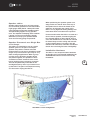
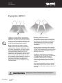
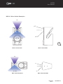
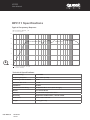
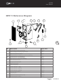
User
Manual
MODEL: HPI111
Contents
Safety Precautions . . . . . . . . . . . . . . . . . . . . . . . . . . . . 1
General Description. . . . . . . . . . . . . . . . . . . . . . . . . . . . 3
Getting The Best From Your HPI111 . . . . . . . . . . . . . . . 4
Flying the HPI111 . . . . . . . . . . . . . . . . . . . . . . . . . . . . . 6
HPI111 Specifications. . . . . . . . . . . . . . . . . . . . . . . . . . 8
HPI111 Reference Diagram. . . . . . . . . . . . . . . . . . . . . . 9
User Manual
HPI Series
HPI111
HPI111
User Manual
Safety Precautions
• Be sure to read the instructions in this section carefully before use.
• Make sure you observe the instructions in this manual as the conventions of safety symbols and
messages are very important.
• We also recommend you keep this instruction manual handy for future reference.
Safety Symbol and Message Conventions
Safety symbols described below are used in this manual to prevent bodily injury and property
damage which could result from mishandling. Before operating your product, read this manual first
and understand the safety symbols and messages so you are thoroughly aware of any risks.
1
WARNING
Indicates a potentially hazardous situation which, if
mishandled, could result in death or serious personal injury.
HPI Series
HPI111
User Manual
HPI111
User Manual
WARNING
When Installing the Unit
When the Unit is in Use
• Do not expose the unit to rain or an
environment where it may be exposed to
water or other liquids, as doing so may
result in damage to the bass driver or
corrosion of the steel protective grill.
• Do not cut, kink, otherwise damage
nor modify the speaker cable. Also use
speaker cable of at least 1.5mm core
diameter. In addition, avoid locating the
speaker cables close to heaters, high
traffic areas or locations where the cables
can be damaged.
2
• Avoid installing or mounting speaker
boxes in unstable locations and when
flying, use the hardware designed for the
speaker box and fix securely to a solid
wall. Failing to do so may result in the
unit falling, causing personal injury and/or
property damage.
• Turn down the amplifier before switching
on the amplifier. If there is no sound,
check the speaker connections. Speakon
connectors must be locked in place.
• Should any of the following irregularities
be found during use, immediately switch
off the amplifier power, disconnect the
power supply plug from the AC outlet and
contact your nearest Quest dealer:
• If you detect smoke or a strange smell
coming from the unit,
• If the unit falls and the unit case is
damaged,
• If it is malfunctioning (no HF or low
frequency output).
Make no further attempt to operate the unit if
it is found to be in any of the above conditions
as this may cause fire or electric shock.
• Be sure to ground to the safety ground
(earth) terminal to avoid electric shock.
Never ground to a gas pipe as a
catastrophic disaster may result.
• Never hang a speaker box from only
one rigging point. Use multiple points
and attach a safety line to a point strong
enough to take the weight of the speaker
box.
WARNING
User Manual
HPI Series
HPI111
Flying the box from one insert must not be attempted!
Improper installation may result in damage, injury or death.
HPI111
User Manual
General Description
The HPI 111 is a full frequency range
multi-purpose 2-way passive speaker system
designed for the live sound touring and
permanent installation market.
It is suited to full range front-of house sound
for mid-throw applications in both stand alone
applications or as part of a small array. Its
versatility means it can also be configured
in multiple numbers as a multi-way system
with sub bass enhancement or individually as
part of a compact portable full range system
with single sub bass enhancement. (See HPI
Series bass speaker systems).
The HPI 111 differs from the HPI 110 in that it
has a wide dispersion 1” horn flare that can
be rotated through four planes of dispersion.
This makes the HPI 111 an ideal choice for
single element installations or as a delay
speaker supporting an HPI 110 array. The
HPI111 requires no special system processor
and can be installed in a vertical or horizontal
installation with the horn flare rotated to give
the appropriate HF dispersion.
Features
The HPI111 has a number of features
designed to increase performance and
versatility for a professional sound installation
environment. A great deal of attention
was paid to the details of the design to
make the HPI111 both sonically excellent
and functionally suited to all aspects of
mobile and permanently installed sound
reinforcement.
High Powered Purpose Designed
Components
A high powered frequency driver is matched
to the 1 inch exit high frequency asymmetrical
wave guide. The result is a reliable and
high fidelity high frequency response with
a uniform mid throw and wide dispersion
capability.
The high efficiency 10” mid-bass transducer
has been designed to function in a relatively
large volume enclosure to maximize low
frequency output. The cone geometry
and driver dynamic parameters are also
engineered to give a smooth frequency
response into the vocal range.
Good vocal and midrange response makes
the HPI111 an exceptional performer when it
comes to vocal projection and reproduction of
acoustic instrumentation.
Functional Design
For easy maneuvering and loading, an
integrated carry handle also doubles as part
of the rigging system and also serves to give
the casing more strength and rigidity.
3
The recessed input panel allows for protection
of the plastic Speakon connectors and also
aids a visually tidy installation.
Solid Build Construction
Built for a touring environment, the HPI111
is well suited to all professional applications.
The timber casing is reinforced birch ply with
a heavy gauge power-coated steel grill. Like
all Quest products, it is “built tough for a
tough world”.
HPI Series
HPI111
User Manual
HPI111
User Manual
Getting The Best From Your HPI111
Connections
Suitable Amplification
The HPI111 is an 8 ohm enclosure and can
be connected in multiple parallel connections
to an amplifier channel that can operate
at speaker impedances of 4 ohms. The
HPI111 is a mid power level high efficiency
system, so ultra high power is not necessary
to obtain high sound pressure levels. The
recommended power range per amplifier
channel is 450-500 watts RMS into an 8Ω load.
The HPI111 is ideal for use with the Quest QA
2004/3004 models.
Two Neutric Speakon model NL-4 connectors
are mounted in a recessed panel on the
rear surface of the box. This allows the
speaker box to be set flat against a wall
without physical interference to the speaker
connector.
Setting the QA amplifier’s high pass filter
at 35Hz is recommended for full range
applications. If you are intending to add
sub bass speakers or use for mainly vocal
reproduction, the high pass filter can be set
to 80Hz.
• The connector input is wired pin 1+ and
pin 1-.
• Pin 2 is not connected.
4
Take care when inserting the Speakon
connector twisting the connector until it
locks into place. Reverse the procedure to
disconnect.
10
10
5
5
1
1
OFF
35Hz
Reducing low frequency output will make more
amplifier power available for clean vocal reproduction
for full range sound, set the high pass filter to 35Hz
80Hz
HIGHPASS-A
1
2
CAUTION
OFF
35Hz
80Hz
STEREO PARALLEL BRIDGE
HIGHPASS-A
OFF
80Hz
1.4V
MODE
32dB
26dB
OUTPUT A
GAIN
RISK OF ELECTRIC SHOCK
DO NOT OPEN
110Hz
LOW PASS-A
LINKA
INPUTA
PIN1: SIGNAL G N D
PIN2: SIG N AL +
PIN3: SIGNA L -
BRIDGE
MODEL :
OUTPUT ASSIGNMENT
PIN1+ :
S IGN A L
PIN1-:
G ROUND
PushToReset
HIGHPASS-B
OFF
35Hz
80Hz
LOW PASS-B
OFF
80Hz
LIMITE
R
110Hz
ON
GROUND
OFF
LIFT
GROUND
DESIGNED BY QUEST ENGINEERING,AUSTRALIA
LINKB
INPU T B
OUTPUT B
~ 220
240V 10A 50/60Hz
Recommended HPI111
Amplifier Configuration
User Manual
HPI Series
HPI111
HPI111
User Manual
Speaker cables
Speaker cable needs to be as heavy gauge
as conveniently possible for low-loss results.
Light gauge cable (below 1.5mm) will create
extra resistance and waste amplifier power.
This particularly applies to long speaker
runs. The amplifier’s damping factor statistic
(“punch” for the non technical) is greatly
diminished, so keep your speaker cables
short and as heavy gauge as practical.
Speaker Placement as a Single Box
or in Arrays
The HPI111 is intended for use as a single
speaker system or as part of a multiple
speaker setup with or without sub bass
reinforcement. It can also be installed in small
arrays of up to three boxes per array for very
wide coverage applications. When a group
of point source 90 degree speaker boxes
are placed together, it is possible to have
“interference effect” between some of the
boxes causing uneven frequency response.
This can be particularly noticeable in the
mid-high frequency area. If you intend to set
up the HPI111 as part of a multiple box array,
see the section ‘Flying the HPI111’.
When positioning the speaker system on a
stage, make sure the HF horn at the top of
the speaker box is above the heads of the
audience. At full power the output of the
HPI111 is very high and hearing damage can
result from short to medium term exposure.
For best results when the HPI111 is used as a
front of house speaker, consider angling the
box forward slightly to direct the HF horn to
cover the audience area. The HF horn should
be aimed away from the ceiling and focused
on the intended area of coverage. This will
minimize HF reflections, lower the reverberant
field in the room and give better intelligibility.
Installation Hardware
The HPI 111 can accept the same hardware
as the HPI 110. For horizontal installation the
ACHPiWB110 bracket can be used for tidy
installation.
5
Ideal HPI111 Flown Configuration
HPI Series
HPI111
User Manual
HPI111
User Manual
Flying the HPI111
6
The HPI 111 can be flown in a permanent
installation by attaching the designed flying
hardware. The HPI111 can be wall mounted
or hung in a flown installation using the flying
fitting accessory. For more information, see
the Quest HPI flying hardware manual.
Before suspending any speaker system
always inspect all components (enclosure,
rigging frames, eyebolts, track fittings, etc.)
for cracks, deformations, corrosion, missing,
loose or damaged parts that could reduce
strength and safety of the array. Do not
suspend the speaker system until the correct
preparation of the installation site has been
taken to avoid health risks during and after
the completion of the installation. A licensed
Professional Engineer must approve the
placement and method of attachment to
the structure prior to the installation of any
overhead object.
Rotating the Horn Flare
The asymmetrical horn flare can be rotated
through three separate planes of dispersion
depending on the speaker box requirement
and installation environment. The planes
are suited to either vertical or horizontal
installations.
Good coverage of audiences often requires
wide dispersion at the base of the horn flare
to cover close listeners and a focused narrow
dispersion at the top of the flare to beam to
the back of the room.
The HPI111 horizontal horn covers both
“short-throw” and “long-throw” requirements
in a single system. For the majority of
installations (where the box is installed
vertically), the asymmetrical horn should be
used as supplied and will not need to be
rotated.
For horizontal installation rotate 45 degrees
so the arrow is pointing at the floor side so
as to have the “beaming” facility at the top of
the horn.
WARNING
User Manual
HPI Series
HPI111
Ensure the box is securely located. If any doubt about the physical
stability, tie the box down with ratchet straps to a secure base.
HPI111
User Manual
HPI111 Wave Guide Examples
45°
+15˚
-45˚
90°-100°
7
HPI111 Vertical Side
HPI111 Vertical Front
45°
+15˚
90°-100°
HPI111 Horizontal Front
-45˚
HPI111 Horizontal Side
HPI Series
HPI111
User Manual
HPI111
User Manual
HPI111 Specifications
Typical Frequency Reponse
HPI111-Frequency Reponse _ 1W
(dB) Level, Sound pressure
110
100
90
80
70
60
8
50
20
50
100
200
500
1k
2k
F: Frequency Response - 1W @ 1m
1/3 octave smoothing
Technical Specifications
User Manual
Power Handling
400W RMS
Frequency Response
70 – 18 kHz (+/-3dB)
Sensitivity 1 watt @ 1 Meter
96dB
Maximum SPL @ 1m
128dB
Impedance
8 ohms
Connections and Wiring
2x Speakon NL4 - 1+/1- (2+/2- through)
Woofer
10” Ferrite Woofer
Tweeter
1” exit ferrite compression driver
Directivity
Asymmetric 90 Horizontal ; +15/-50 vertical
Dimensions
641.5 x 306 x 352 mm
Weight
19.4Kg (42.7 lbs)
HPI Series
HPI111
5k
10k
20k
Frequency (Hz)
HPI111
User Manual
HPI111 Reference Diagram
1
3
4
4bis
9
8
11
12
8
10
2
5bis
5
1
9
7
7bis
6
No.
Description
Spare Part
1
Complete grille (includes acoustic foam)
HGHPI111
2
Rotative Q-badge 25mm (with spring-loaded pin)
HQB25
3
Asymmetric horn flares for HPI111
HWG111
4
Compression Driver 1” exit (ferrite, 1.75”voice-coil, 40Wrms)
T1012
4bis
Compression driver recone (diaphragm)
RT1012
5
Woofer (ferrite 10", 2.5"voice-coil, 300Wrms)
T10005
5bis
Woofer dedicated recone kit
RT10005
6
Steel pole mount bottom plate
HPP110
7
Rubber skids (137mm)
HSK137
7bis
Rubber skids (52mm)
HSK52
8
Internal metal brace - 1 (Top)
HIB110-1
9
Internal metal brace - 2(Centre)
10
Internal metal brace - 3(Bottom)
11
Aluminum handle for HPI111
12
Connection plate
HCP110
13
Passive filter network for HPI111 (x-over)
AXHPI111
14
Manufacturer plate for HPI110
HIB110-2
HIB110-3
HAH111
HMP110
HPI Series
HPI111
User Manual
Register Your Product
Thank you for choosing Quest. Please take the time
to complete your product registration card which is
included with the packaging.
Registering your Quest Engineering product will:
• CONFIRM YOUR WARRANTY
• REGISTER YOUR PRODUCT
• PROTECT YOUR NEW PRODUCT
REGISTER ONLINE:
www.questaudio.net/registration
www.questaudio.net