1
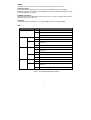
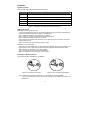
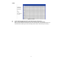
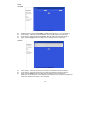
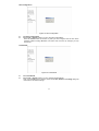
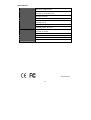
User’s Manual
EtherFast 10/100M Smart Switch
Model No.: SP616DB / SP624DB
http://www.micronet.info
Package Contents
Verify your package contains the following items:
z SP616DB/SP624DB 10/100 Mbps Smart Switch
z User’s Manual
z Power Cord
z Rack Ears with Screws and Rubber Foots
Features
Micronet SP616DB/SP624DB has the following key features:
z Provide 16 (SP616DB) or 24 (SP624DB) RJ-45 ports of 10/100 Mbps, auto negotiation
z Provide one expansion slot for optional fiber optic module
z Provide one web-based console port
z Provide 2K (SP616DB)/10K (SP624DB) MAC address and 2M (SP616DB)/1.5M (SP624DB)
buffer memory
z Provide 16 (SP616DB) or 24 (SP624DB) port-based VLAN groups to segment network
z Provide 2 trunking groups to aggregate bandwidth
z Provide auto-uplink function, no more cross-over cable
z Support store-and-forward mechanism
z Support non-blocking wire speed forwarding rate
z Suitable for rack-mount installation
Physical Description
Front Panel
Figure 1: Front Panel of SP616DB
Figure 2: Front Panel of SP624DB
2
POWER
This LED comes on when the switch is properly connected to power and turned on.
TX/FX Push Button
The push button is located at the right side of port 16 (SP616DB) or port 24 (SP624DB).
Release this button to use RJ-45 port 16 (SP616DB) or port 24 (SP624DB), and press this button
to use the 100BASE-FX module.
IP RESET Push Button
Press the front panel IP RESET push button for around five seconds to reset the Switch back to
default IP Address (192.168.1.10).
Port Status
The RJ-45 ports are numbered from 1 to 16 (SP616DB), or from 1 to 24 (SP624DB).
LEDs
Label
Status
Indication
POWER
On
Power is feeding in.
Off
Power is switched off.
Improper connection.
CONSOLE
LNK
ACT
PORT
LNK/ACT
On
A valid network connection. LNK stands for LINK.
Off
No connection.
Flashing Transmitting or receiving data. ACT stands for
ACTIVITY.
Off
Neither connection nor activity.
On
A valid network connection. LNK stands for LINK.
Flashing Transmitting or receiving data. ACT stands for
ACTIVITY.
SPEED
FX
LNK
ACT
Off
Neither connection nor activity.
On
A valid 100Mbps connection.
Off
A valid 10Mbps connection.
On
A valid network connection. LNK stands for LINK.
Off
No connection.
Flashing Transmitting or receiving data. ACT stands for
ACTIVITY.
Off
Neither transmitting nor receiving data.
Table 1: SP616DB/SP624DB LED Indication
3
Installation
Preparing the Site
Select the site that meets the following requirements:
Characteristic Requirement
Temperature 32 to 104˚F (0 to 40˚C)
Humidity
Maximum relative humidity of 90%, non-condensing
Condition
At least 1.8 meters (6 feet) to the nearest source of electromagnetic noise
Ventilation
Minimum 3 inches (0.25 feet) of clearance around the ventilation openings
Power Outlet Within 1.8 meters (6 feet) to the switch
Table 2: SP616DB / SP624DB Operating Requirements
Settling the Switch
z Mounted to 19-inch standard rack
Locate the accessories provided in the product package. Use the rack-mount brackets and
screws to install the switch into any EIA 19” standard rack.
Step 1: Attach the brackets to each side of the chassis.
Step 2: Apply the screws to each side and secure them tightly.
Step 3: Carefully position the switch into the rack.
Step 4: Align the brackets to the side holes on the rack and use rack screws to secure the
chassis with the rack.
Step 5: Proceed to the “Connecting to Power” section.
z Desktop or any flat surface
The switch can sit on desktop or any flat surface with adequate space and ventilation. If you
want to place it onto a shelf, make sure the shelf can withstand the weight of the switch.
Step 1: Simply put the switch on the desired place.
Step 2: Ensure the switch receives good ventilation.
Step 3: Proceed to the “Connecting to Power” section.
Installing the Module (optional)
Consult the following illustrations for installation.
Figure 3: Removal of cover plate
Figure 4: Fiber module being installed
Step 1: Make sure the power is switched off. The module is not hot-swappable.
L It may cause electric shock or any possible damage to the switch if the power is not
switched off.
4
Step 2: Remove the module from the static-free container.
Step 3: Unscrew the cover plate of the expansion slot.
(The slot for single-port module is located at the right side of the switch.)
Step 4: Remove the plate.
(Keep it for future use in case you decide to remove this module later.)
Step 5: Carefully slide the module into the slot, along the internal plastic guide rails.
Step 6: Once it is fully slid in, snap in the module to make a proper connection.
Step 7: Fasten the module screws then.
Step 8: Finally, turn on the power.
Connecting to Power
Locate the provided AC power cord.
Step 1: Connect the AC power cord to the receptacle at the back of the switch.
Step 2: Attach the plug into a standard AC outlet with a voltage ranging from 100 to 240 VAC.
Step 3: The power LED on the front panel will come on then.
Connecting to Network
Step 1: First, ensure the power of the switch (and end devices) is turned off.
L It may cause electric shock or any possible harm to you if the power is not switched off.
Step 2: Prepare cable with corresponding connectors for each type of port in use.
Step 3: Connect one end of the cable to the switch and the other end to a desired device.
Step 4: Once the connections between two end-devices are made successfully, turn on the
power.
Now the switch is operational.
5
Switch Configuration
Setting UP Console Port Connection
SP616DB/SP624DB provides one RJ-45 console port and a web-based interface, allowing users
to configure and manage the switch remotely from web browser.
1.
Connect UTP/STP cable to SP616DB/SP624DB’s console port.
Figure 5: Connect directly to PC
2.
Figure 6: Connect to PC via another switch
In the web browser, specify the default IP address of SP616DB/SP624DB (192.168.1.10).
Default User Name: admin
Default Password: (null)
Figure 7: Switch Configuration Login
Main Menu
6
Figure 8: Main menu
System Change
The System Change parameters can be displayed by clicking the System Change button in the
left sub-menu.
Figure 9: System Change
z
z
z
Switch Name: Type a switch name and replace the current switch name with a new one.
(Please restart your Computer once the Switch Name is replaced and saved under
“Save Configuration “by the new name ).
Note: only “a-z “, “A-Z”, “0-9”, “under line” & “Space” can be acceptable, totally can not
exceed 16 characters.
Password: Enter a user-defined password and change the factory default password.
Note: only “a-z “, “A-Z”, “0-9”, “under line” & “Space” can be acceptable, totally can not
exceed 16 characters.
Apply: Click the Apply button and apply the new System settings.
7
IP Configuration
Figure 10: IP Configuration
z
z
z
Refresh: Click the Refresh button and refresh back to the last saved IP Configurations.
IP Address, Netmask, Default Gateway: You can see and change the IP Address, Netmask,
and Default Gateway of the Ethernet Switch.
Apply: Click the Apply button and apply the new IP Configurations.
Port
Figure 11: Port
z
z
z
z
z
Refresh: Click the Refresh On or Refresh Off button to or not to refresh back to the last
saved settings of the ports.
Note: it is recommended to change the Refresh On button to Refresh Off while you
change the settings of the ports. The Refresh On will refresh the settings of the ports
shown on the screen around every ten seconds.
Mode: Choose AUTO, 10HD, 10FD, 100HD or 100FD for the ports.
Flow Control: Choose Enable or Disable to enable or disable the flow control of the ports.
Transmit / Receive: Choose On or Off to turn on or off transmit / receive of the ports.
Apply: Click the Apply button and apply the new settings of the ports.
8
VLAN
Figure 12: VLAN
z
z
VLAN: Click and choose the ports to be added into the VLAN groups.
Apply: Click the Apply button and apply the new settings of the VLAN groups.
Note: all Ports have to be selected to one of the VLAN Groups, those Port/Ports were not
selected will be notified by the alarm message which shows “Non-Identify VLAN Group “.
9
Trunk
SP616DB:
Figure 13: Trunk of SP616DB
z
z
z
z
Disable: Click and choose the Disable to disable the Trunk Group 1 or Trunk Group 2.
Trunk Group 1: Click and choose the Port 1, 2 to be added into the Trunk Group 1.
Trunk Group 2: Click and choose the Port 9, 10 to be added into the Trunk Group 2.
Apply: Click the Apply button and apply the new settings of the Trunk Groups.
SP624D:
Figure 14: Trunk of SP624DB
z
z
z
Trunk Group 1: Click and choose any four ports to be added into the Trunk Group 1.
Trunk Group 2: Click and choose any four ports to be added into the Trunk Group 2.
Apply: Click the Apply button and apply the new settings of the Trunk Groups.
Note: each Trunk Group can not be selected more than four ports, the alarm message will
show “Non-Identify Trunk Group“, if it’s exceeded.
10
Save Configuration
Figure 15: Save Configuration
z
z
Click Save Configuration.
Click the Ok or Cancel button to or not to save the configurations.
Note: the Cancel button will discard any data you have changed since the last "Save"
operation. Without clicking Ok button, the switch does not save any changes you may
have made.
Load Default
Figure 16: Load Default
z
z
Click Load Default.
Click the Ok or Cancel button to or not to load the default settings.
Note: once the Ok button is selected, all last saved Port, VLAN, and Trunking setting will
revert back to the default settings.
11
Specifications
IEEE standard
IEEE 802.3,10BaseT
IEEE 802.3u,100BaseTX/FX
Port
SP616DB: 16 10/100 Mbps ports
SP624DB: 24 10/100 Mbps ports
Speed
200 Mbps full-duplex
100 Mbps half-duplex
Dimension
440 × 207 × 44 mm rack-mount size
Weight
SP616DB: 1.94 kg
SP624DB: 2.07 kg
Power Input
100 - 240 VAC, 50 - 60 Hz
Input Fuse
SP616DB: 3.3VDC, 2.5A
SP624DB: 3.3VDC, 5A; 5V, 1A
Power Consumption
SP616DB: 8.25W Max.
SP624DB: 21.5W Max.
Operating Temperature
32 to 104˚F (0 to 40˚C)
Storage Temperature
-13 to 158˚F (-25° to 70°C)
Humidity
10 - 90%, non-condensing
Emission
FCC part 15 Class A, CE Mark
P/N 2300-0180
12