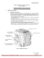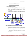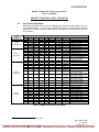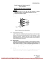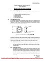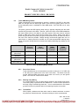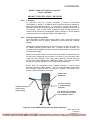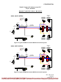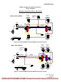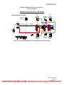
1
CONFIDENTIAL
Bendix Commercial Vehicle Systems
Elyria, OH 44036
PRODUCT SPECIFICATION BW-283-PR
ANTILOCK BRAKING SYSTEM
TABS6 STANDARD & PREMIUM MODEL
TRAILER ABS MODULE
NOTICE
Bendix Commercial Vehicle Systems LLC claims proprietary rights to the
information contained herein. This document is furnished in confidence with
the express understanding that neither it nor any copy thereof shall be
disclosed to others nor used for the purpose of manufacture or procurement
of the article documented herein, without written permission from Bendix.
© 2004 Bendix Commercial Vehicle Systems LLC, All Rights Reserved.
T. S. Legeza
WRITTEN
DATE
10/01/04
09/30/04
DATE
REVISED
INIT.
TSL
PRODENGR FORM 003.DOC
ECN NO.
72193
T. J. Frashure
APPROVED
DATE
SPEC. BW-283-PR
73 SHEETS
SHEET NO. 1
REVISED 2000/10/17
DOCUMENTO CONTROLADO DE FORMATO ELECTRÓNICO: Antes de utilizarlo se requiere verificar el nivel de revision o la suficiencia.
CONTROLLED ELECTRONIC MEDIA DOCUMENT: Verification of revision level or adequacy is required prior to use.
CONFIDENTIAL
Bendix Commercial Vehicle Systems LLC
Elyria, OH 44036
PRODUCT SPECIFICATION - BW-283-PR
Table of Contents
1
SCOPE ................................................................................................................................................................. 7
1.1
DESCRIPTION ................................................................................................................................................. 7
1.2
SPECIFICATIONS ............................................................................................................................................. 7
1.2.1
Bendix Commercial Vehicle Systems Specifications ............................................................................. 7
1.2.2
SAE Documents..................................................................................................................................... 7
1.2.3
Government Documents ........................................................................................................................ 8
1.2.4
Standards .............................................................................................................................................. 8
1.2.5
Abbreviations and Symbols ................................................................................................................... 8
2
GENERAL PRODUCT DESCRIPTION.......................................................................................................... 9
2.1
2.2
2.3
3
TRAILER ANTILOCK BRAKING SYSTEM (TABS)............................................................................................ 9
ABS CONTROL MODES .................................................................................................................................. 9
ABS VEHICLE INSTALLATION SCHEMATIC .................................................................................................. 10
SYSTEM COMPONENTS............................................................................................................................... 11
3.1
TABS6 TRAILER ABS MODULE .................................................................................................................. 11
3.1.1
Modulator Relay Valve (MRV) Crack Pressure .................................................................................. 13
3.1.2
Control Line Filter .............................................................................................................................. 13
3.1.3
FMVSS 121 Timing ............................................................................................................................. 13
3.1.4
ECU Identification & Connector Pin-Out........................................................................................... 13
3.1.5
ECU Power Circuit ............................................................................................................................. 15
3.1.6
Communication Data Links................................................................................................................. 15
3.1.7
ECU Speed Sensor Input Circuits ....................................................................................................... 16
3.1.8
ABS Warning Light Circuit ................................................................................................................. 16
3.1.9
Auxiliary Inputs & Outputs (I/O) ........................................................................................................ 17
3.1.10 Power-Up Sequence (functions).......................................................................................................... 18
3.1.11 Auto-Configuration (Premium TABS6 only) ....................................................................................... 18
3.1.12 Auxiliary Design Language (ADL)...................................................................................................... 19
3.1.13 Customer Scratch Pad......................................................................................................................... 19
3.1.14 Odometer Functions............................................................................................................................ 20
3.1.15 System Schematic Diagrams ............................................................................................................... 20
3.2
TABS6 TRAILER ABS WIRE HARNESSES .................................................................................................... 23
3.3
WS-24 WHEEL SPEED SENSOR (WSS)......................................................................................................... 24
3.3.1
WS-24 WSS Specifications .................................................................................................................. 25
3.4
BR9235 MODULATOR RELAY VALVE (MRV) ............................................................................................ 26
3.4.1
BR9235 MRV Specifications ............................................................................................................... 26
4
TABS6 OPERATING CONDITIONS ............................................................................................................ 28
4.1
ELECTRICAL................................................................................................................................................. 28
4.1.1
Power Requirements ........................................................................................................................... 28
4.1.2
Steady State Operation........................................................................................................................ 28
4.1.3
ECU Housing Degree of Protection.................................................................................................... 28
4.1.4
Load Dump.......................................................................................................................................... 28
4.1.5
Inductive Switching ............................................................................................................................. 29
4.1.6
Mutual Coupling ................................................................................................................................. 29
4.1.7
Power Line Noise ................................................................................................................................ 29
4.1.8
Over-Voltage During Jump Start ........................................................................................................ 29
SPEC. BW-283-PR
73 SHEETS
SHEET NO. 2
DOCUMENTO CONTROLADO DE FORMATO ELECTRÓNICO: Antes de utilizarlo se requiere verificar el nivel de revision o la suficiencia.
CONTROLLED ELECTRONIC MEDIA DOCUMENT: Verification of revision level or adequacy is required prior to use.
CONFIDENTIAL
Bendix Commercial Vehicle Systems LLC
Elyria, OH 44036
PRODUCT SPECIFICATION - BW-283-PR
4.1.9
Electrostatic Discharge....................................................................................................................... 30
4.1.10 Electromagnetic Compatibility ........................................................................................................... 30
4.2
TEMPERATURE ............................................................................................................................................. 30
4.2.1
Operating Range ................................................................................................................................. 30
4.2.2
Storage Range ..................................................................................................................................... 30
4.2.3
Thermal Cycle ..................................................................................................................................... 30
4.2.4
Humidity.............................................................................................................................................. 30
4.3
PRESSURE .................................................................................................................................................... 31
4.3.1
Maximum Operating Pressure ............................................................................................................ 31
4.3.2
Over-Pressurization ............................................................................................................................ 31
4.4
MECHANICAL............................................................................................................................................... 31
4.4.1
Random Vibration - Frame Mount..................................................................................................... 31
4.4.2
Random Vibration - Tank Mount........................................................................................................ 31
4.4.3
Mechanical Shock ............................................................................................................................... 32
4.4.4
Drop Test............................................................................................................................................. 32
4.5
CLIMATE ...................................................................................................................................................... 32
4.5.1
Combined Environment “AGREE”..................................................................................................... 32
4.5.2
Chemical Exposure ............................................................................................................................. 32
4.5.3
High Pressure Wash............................................................................................................................ 33
4.5.4
Salt Fog ............................................................................................................................................... 33
4.5.5
Gravel Bombardment .......................................................................................................................... 33
5
TABS6 DIAGNOSTICS ................................................................................................................................... 34
5.1
FAULT DETECTION ....................................................................................................................................... 34
5.1.1
Active Faults ....................................................................................................................................... 34
5.1.2
Event History Log ............................................................................................................................... 35
5.2
SYSTEM FAULTS .......................................................................................................................................... 35
5.2.1
ECU Faults ......................................................................................................................................... 35
5.2.2
Power Supply Diagnostics .................................................................................................................. 35
5.2.3
Wheel Speed Sensing........................................................................................................................... 36
5.2.4
Modulator Diagnostics........................................................................................................................ 37
5.2.5
Auxiliary Output Diagnostics.............................................................................................................. 38
5.3
PARTIAL FAILURE ABS MODES ................................................................................................................... 39
5.4
BLINK CODE DIAGNOSTICS .......................................................................................................................... 40
5.4.1
Blink Code Diagnostics - Activation ................................................................................................... 40
5.4.2
Blink Code Diagnostics - Activation Modes........................................................................................ 40
5.4.3
Blink Code Diagnostics - Lamp Timing .............................................................................................. 41
5.4.4
Blink Code Diagnostics – Diagnostic Troubleshooting Code (DTC).................................................. 41
5.4.5
Blink Code Diagnostics – Clear Active Faults Codes......................................................................... 46
5.4.6
Blink Code Diagnostics - System Configuration Check ...................................................................... 47
5.4.7
Blink Code Diagnostics - Odometer Mileage Display ........................................................................ 47
5.4.8
Blink Code Diagnostics – Reset ECU Configuration.......................................................................... 47
5.5
OFF-BOARD DIAGNOSTICS........................................................................................................................... 48
5.5.1
SAE J2497 PLC Diagnostics............................................................................................................... 48
5.5.2
SAE J1587 Diagnostic Connector....................................................................................................... 48
5.5.3
Bendix® ACOM™ Diagnostic Software ............................................................................................. 49
5.5.4
Pro-Link™ Support............................................................................................................................. 49
5.5.5
Trailer Remote Diagnostic Unit (TRDU) ............................................................................................ 49
5.6
TECHNICAL ASSISTANCE ............................................................................................................................. 50
5.6.1
Technical Assistance (Internet) ........................................................................................................... 50
SPEC. BW-283-PR
73 SHEETS
SHEET NO. 3
DOCUMENTO CONTROLADO DE FORMATO ELECTRÓNICO: Antes de utilizarlo se requiere verificar el nivel de revision o la suficiencia.
CONTROLLED ELECTRONIC MEDIA DOCUMENT: Verification of revision level or adequacy is required prior to use.
CONFIDENTIAL
Bendix Commercial Vehicle Systems LLC
Elyria, OH 44036
PRODUCT SPECIFICATION - BW-283-PR
5.6.2
6
Bendix® Technical Assistance Team.................................................................................................... 50
INSTALLATION .............................................................................................................................................. 51
6.1
TABS6 TRAILER ABS ASSEMBLY MOUNTING ............................................................................................ 51
6.1.1
Reservoir Mount Configuration .......................................................................................................... 51
6.1.2
Frame Mount Configuration ............................................................................................................... 52
6.2
WHEEL SPEED SENSOR INSTALLATION REQUIREMENTS .............................................................................. 53
6.2.1
Sensor Mounting Block ....................................................................................................................... 53
6.2.2
Wheel Speed Sensor Clamping Sleeve Installation ............................................................................. 55
6.2.3
Wheel Speed Sensor Installation ......................................................................................................... 55
6.2.4
Sensor Displacement Force ................................................................................................................ 56
6.2.5
Sensor Wiring Requirements............................................................................................................... 56
6.3
EXCITER RING INSTALLATION REQUIREMENTS............................................................................................ 58
6.3.1
Material............................................................................................................................................... 58
6.3.2
Installation .......................................................................................................................................... 58
6.3.3
Stamped Steel Exciter Ring ................................................................................................................. 59
6.3.4
Machined Steel.................................................................................................................................... 59
6.3.5
Oil Seals .............................................................................................................................................. 59
6.3.6
Exciter Ring Damage .......................................................................................................................... 60
6.4
TRAILER ABS WARNING LAMP ................................................................................................................... 60
6.4.1
Trailer Lamp Location ........................................................................................................................ 60
6.4.2
Dolly Lamp Location........................................................................................................................... 60
6.5
TRAILER ABS WIRING DETAILS .................................................................................................................. 61
6.5.1
Power from Tractor............................................................................................................................. 61
6.5.2
Warning Lamp Wiring......................................................................................................................... 61
6.5.3
Twisted Pair ........................................................................................................................................ 61
6.5.4
Connectors .......................................................................................................................................... 62
6.5.5
Routing and Securing of Wires............................................................................................................ 62
6.6
OEM END-OF-LINE (EOL) TESTING ............................................................................................................ 63
7
ANTILOCK APPLICATION CHECK LIST ................................................................................................ 64
8
APPLICATIONS .............................................................................................................................................. 68
8.1
RANGE OF APPLICATION .............................................................................................................................. 68
8.2
SPECIAL CONSIDERATIONS .......................................................................................................................... 69
8.2.1
Spring Brake Control Valve (SR-5)..................................................................................................... 69
8.2.2
Non-Spring Brake Emergency Function ............................................................................................. 69
8.2.3
Choosing The Axle To Place Wheel Speed Sensors ............................................................................ 69
8.3
APPLICATION DIAGRAMS ............................................................................................................................. 70
SPEC. BW-283-PR
73 SHEETS
SHEET NO. 4
DOCUMENTO CONTROLADO DE FORMATO ELECTRÓNICO: Antes de utilizarlo se requiere verificar el nivel de revision o la suficiencia.
CONTROLLED ELECTRONIC MEDIA DOCUMENT: Verification of revision level or adequacy is required prior to use.
CONFIDENTIAL
Bendix Commercial Vehicle Systems LLC
Elyria, OH 44036
PRODUCT SPECIFICATION - BW-283-PR
List of Figures
Figure 1: General Schematic of a Trailer ABS in 4S/2M Configuration ............................................................. 10
Figure 2: TABS6 Module Design ............................................................................................................................. 11
Figure 3: ECU Identification & Pin-Out - Standard TABS6 ................................................................................ 13
Figure 4: ECU Identification & Pin-Out - Premium TABS6 ................................................................................ 14
Figure 5: Example Trailer Applications via Auxiliary Design Language (ADL) ................................................ 19
Figure 6: Schematic Diagram Standard TABS6 2S/1M ........................................................................................ 20
Figure 7: Schematic Diagram Premium TABS6 2S/1M ........................................................................................ 21
Figure 8: Schematic Diagram Premium TABS6 2S/2M ........................................................................................ 21
Figure 9: Schematic Diagram Premium TABS6 4S/2M ........................................................................................ 22
Figure 10: Schematic Diagram Premium TABS6 4S/3M ...................................................................................... 22
Figure 11: TABS6 Wire Harness – Standard Harness (Ref. Drw. 5015013) ....................................................... 23
Figure 12: TABS6 Wire Harness – Premium Harness (Ref. Drw. 5015018) ....................................................... 23
Figure 13: TABS6 Wire Harness – Wheel Speed Extension Cable (Ref. Drw. 6000365) ................................... 24
Figure 14: TABS6 Wire Harness – Remote Modulator Extension Cable (Ref. Drw. 5013343) ......................... 24
Figure 15: TABS6 Wire Harness – Diagnostic Extension Cable (Ref. Drw. 5007833)........................................ 24
Figure 16: Wheel Speed Sensor with Tone Wheel.................................................................................................. 25
Figure 17: BR9235 Modulator Relay Valve (MRV)............................................................................................... 26
Figure 18: ECU Identification & Pin-Out - Premium TABS6 .............................................................................. 48
Figure 19: TABS6 Reservoir Mount ....................................................................................................................... 51
Figure 20: TABS6 Frame Mount............................................................................................................................. 52
Figure 21: TABS6 Frame Mount Hole Pattern ...................................................................................................... 52
Figure 22: Wheel Speed Sensor Mounting Block ................................................................................................... 53
Figure 23: Wheel Speed Sensor Mounting Block Installation............................................................................... 54
Figure 24: Preferred Wheel Speed Sensor Mounting Block Location ................................................................. 55
Figure 25: Sensor Clamping Sleeve and Sensor Installation................................................................................. 56
Figure 26: Wheel Speed Sensor Wire Routing ....................................................................................................... 57
Figure 27: Maximum Exciter Ring Run-Out ......................................................................................................... 59
Figure 28: Trailer ABS Warning Lamp.................................................................................................................. 60
Figure 29: Trailer ABS Routing & Securing of Wire Harnesses .......................................................................... 62
Figure 29: ABS System Application Chart ............................................................................................................. 68
Figure 30: Wheel Speed Sensor Placement............................................................................................................. 69
Figure 31: Typical 2S-1M Axle Control ABS Electrical and Air System............................................................. 70
Figure 32: Typical 2S-1M Dolly-Axle Control ABS Electrical and Air System .................................................. 70
Figure 33: Typical 2S-2M Axle Control ABS Electrical and Air System............................................................. 71
Figure 34: Typical 2S-2M Side Control ABS Electrical and Air System ............................................................. 71
Figure 35: Typical 4S-2M Axle Control ABS Electrical and Air System............................................................. 72
Figure 36: Typical 4S-2M Side Control ABS Electrical and Air System ............................................................. 72
Figure 37: Typical 4S-3M Side/Axle Control ABS Electrical and Air System .................................................... 73
SPEC. BW-283-PR
73 SHEETS
SHEET NO. 5
DOCUMENTO CONTROLADO DE FORMATO ELECTRÓNICO: Antes de utilizarlo se requiere verificar el nivel de revision o la suficiencia.
CONTROLLED ELECTRONIC MEDIA DOCUMENT: Verification of revision level or adequacy is required prior to use.
CONFIDENTIAL
Bendix Commercial Vehicle Systems LLC
Elyria, OH 44036
PRODUCT SPECIFICATION - BW-283-PR
List of Tables
Table 1: TABS6 Module Part Numbers & Features.............................................................................................. 12
Table 2: TABS6 Auxiliary Input & Outputs (I/O’s) Matrix ................................................................................. 17
Table 3: Standard TABS6 Auxiliary (AUX) Capabilities ..................................................................................... 17
Table 4: TABS6 Auxiliary Electrical Characteristics............................................................................................ 17
Table 5: TABS6 Premium Auto-Configuration Matrix......................................................................................... 18
Table 6: WS-24 WSS Specifications ........................................................................................................................ 25
Table 7: BR9235 MRV Solenoid Characteristics ................................................................................................... 26
Table 8: TABS6 Partial Failure ABS Modes .......................................................................................................... 39
Table 9: Brake Lamp Power Activation Timing - (Blink Codes).......................................................................... 40
Table 10: Blink Code Diagnostics - Activation Modes........................................................................................... 40
Table 11: Blink Code Diagnostics – Lamp Timing ................................................................................................ 41
Table 12: Blink Code – Fault Description & Repair Information ........................................................................ 41
Table 13: Blink Code – ABS Configurations .......................................................................................................... 47
Table 14: Blink Code Diagnostics – ECU Reset Configurations........................................................................... 48
Table 15: TRDU – LED Description ....................................................................................................................... 49
Table 16: Trailer ABS Wiring Requirements......................................................................................................... 61
Table 17: TABS6 OEM Application Check-List .................................................................................................... 64
SPEC. BW-283-PR
73 SHEETS
SHEET NO. 6
DOCUMENTO CONTROLADO DE FORMATO ELECTRÓNICO: Antes de utilizarlo se requiere verificar el nivel de revision o la suficiencia.
CONTROLLED ELECTRONIC MEDIA DOCUMENT: Verification of revision level or adequacy is required prior to use.
CONFIDENTIAL
Bendix Commercial Vehicle Systems LLC
Elyria, OH 44036
PRODUCT SPECIFICATION - BW-283-PR
1
Scope
This document provides technical information about the function, performance, and installation
requirements of the Bendix Trailer Antilock Brake System (ABS) Module, referred to as TABS6. It
is important to read this information to ensure the best performance and safety of the ABS
system.
1.1
Description
The technical information included in this document explains the function and operational
requirements of the TABS6 in detail. Brief explanations of the other system components
are included along with references to their individual specifications. Service and
installation instructions are also included in this document.
1.2
Specifications
1.2.1
Bendix Commercial Vehicle Systems Specifications
BW-120-A
Application
Wheel Speed Sensor Customer Interface
Recommendations
Y0018267_EN
Design
TABS6 SAE J1587 & SAE 2497 - Public
Proprietary Commands and Parameter
Identifiers
Y0018268_EN
Design
TABS6 SAE J1587 & SAE 2497 - Parameter
Descriptions
BW-196-PR
Product
SR-5 Trailer Spring Brake Valve
BW-260-PR
Product
WS-24 Variable Reluctance Wheel Speed
Sensor
BW-269-PR
Product
WS-24 Wheel Speed Sensor Clamping Sleeve
BW-284-PR
Product
Trailer Remote Diagnostic Unit (TRDU)
SD-13-4767
Service
TABS6 ABS Module
5014015
Drawing
TABS6 ABS Module
5015013
Drawing
TABS6 Standard ABS Pigtail Harness
5015018
Drawing
TABS6 Premium ABS Pigtail Harness
6000365
Drawing
Wheel Speed Extension Cable
5013343
Drawing
Remote Modulator Extension Cable
5007833
Drawing
Diagnostic Extension Cable
1.2.2
SAE Documents
SAE J400
Test for Chip Resistance of Surface Coatings
SAE J560
Seven Conductor Electrical Connector for Truck-Trailer Jumper Cable
SAE J1113-13
Electromagnetic Compatibility Measurement Procedure for Vehicle
Components - Immunity to Electrostatic Discharge
SAE J1455
Joint SAE/TMC Recommended Environmental Practices for
Electronic Equipment Design (Heavy Duty Truck)
SAE J1587
Electronic Data Interchange Between Microcomputer Systems in
Heavy-Duty Vehicle Applications
SAE J1708
Serial Data Communications Between Microcomputer Systems in
Heavy-Duty Vehicle Applications
SAE J2497
Power Line Communications for Commercial Vehicles
SPEC. BW-283-PR
73 SHEETS
SHEET NO. 7
DOCUMENTO CONTROLADO DE FORMATO ELECTRÓNICO: Antes de utilizarlo se requiere verificar el nivel de revision o la suficiencia.
CONTROLLED ELECTRONIC MEDIA DOCUMENT: Verification of revision level or adequacy is required prior to use.
CONFIDENTIAL
Bendix Commercial Vehicle Systems LLC
Elyria, OH 44036
PRODUCT SPECIFICATION - BW-283-PR
1.2.3
Government Documents
FMVSS 121
Department of Transportation, National Highway Traffic Safety
Administration Federal Motor Vehicle Safety Standard 571.121
1.2.4
Standards
RP-1210A
RP-137A
RP-141
1.2.5
TMC Recommended Practice for Windows™ Communications API
TMC Recommended Practice for ABS Electrical Supply from
Tractors through the SAE J560 Seven-Pin Connector
TMC Recommended Practice for Trailer ABS Power Supply
Requirements
Abbreviations and Symbols
ABS
Antilock Brake System
ADL
Auxiliary Design Language
AUX
Auxiliary
DTC
Diagnostic Troubleshooting Code
ECU
Electronic Control Unit
EEPROM
Electrically Erasable Programmable Read-Only Memory
EOL
End-Of-Line
ESD
Electrical Static Discharge
FMVSS
Federal Motor Vehicle Safety Standard
I/O
Input / Output
ISS
Integrated Speed Switch
LED
Light Emitting Diode
MOD
Modulator
MPH
Mile Per Hour
MRV
Modulator Relay Valve
NPT
National Pipe Thread
OEM
Original Equipment Manufacture
PC
Personal Computer
PLC
Power Line Communication
RF
Radio Frequency
RP
Recommended Practice
RPS
Revolutions Per Second
RT
Room Temperature
RTR
Reset To Ride
SAE
Society of Automotive Engineers
SAL
Sensor – Additional Right
SAR
Sensor – Additional Left
SL
Sensor – Left
SR
Sensor – Right
TABS
Trailer Antilock Brake System
TMC
Trailer Maintenance Council
TRDU
Trailer Remote Diagnostic Unit
UV
Ultra-Violet
VAC
Voltage – Alternating Current
VDC
Voltage - Direct Current
VIN
Vehicle Identification Number
WSS
Wheel Speed Sensor
SPEC. BW-283-PR
73 SHEETS
SHEET NO. 8
DOCUMENTO CONTROLADO DE FORMATO ELECTRÓNICO: Antes de utilizarlo se requiere verificar el nivel de revision o la suficiencia.
CONTROLLED ELECTRONIC MEDIA DOCUMENT: Verification of revision level or adequacy is required prior to use.
CONFIDENTIAL
Bendix Commercial Vehicle Systems LLC
Elyria, OH 44036
PRODUCT SPECIFICATION - BW-283-PR
2
General Product Description
2.1
Trailer Antilock Braking System (TABS)
®
The Bendix TABS is an electronic system that prevents wheel lock-up during braking to
maintain optimal vehicle steer-ability and stability, as well as minimizing stopping
distance.
The TABS intervenes during braking whenever the available friction between the road
and the tire of a monitored wheel is less than the braking force applied to the wheel
causing the wheel to decelerate (impending wheel lock) quickly.
The system consists of the following components:
• Electronic Control Unit (ECU) monitors the speed sensor signals and determines
when ABS intervention is required. It then actuates the appropriate pressure
modulator valves to optimize the brake pressure. The ECU continually monitors the
system to detect and warn the driver of any malfunctions. Diagnostic Troubleshooting
Codes (DTC) are stored in the ECU and can be recalled to diagnose a failure.
• Wheel Speed Sensors (WSS) located at the wheels to sense the instantaneous
movement of individual wheels and to send an electrical signal directly proportional to
the rotational velocity of the sensed wheel to the electronic control unit.
• Modulator Relay Valves (MRV) located near the brake chambers and are controlled
electrically by the ECU to decrease, hold or allow the full applied brake pressure into
the brake chamber to control the braking torque at the wheels.
• Trailer ABS Warning Lamp is controlled by the ECU as required to indicate ABS
status. The trailer ABS warning lamp will illuminate when ignition power is applied to
the ECU, and extinguish after a lamp check is performed if there are no ABS faults
present.
2.2
ABS Control Modes
Several ABS control modes can be utilized for monitoring and controlling the individual
wheels of the trailer. The possible modes are:
•
•
Axle Control: TABS axle control will utilize a single ABS modulator-valve to control
wheels from both sides of a given axle or axles. In the case of an unbalanced
braking surface, axle control will control the high coefficient wheel just under the lock
limit. Temporary periods of wheel lock are permitted on the low coefficient wheel.
Axle control should not be used on fifth wheel dollies or steerable axles. When
braking on even surfaces, an axle-control system will perform similar to a side
control, two-modulator system. Axle control is available in 2S/1M, 2S/2M and 4S/2M
installations.
Dolly-Axle Control (Select Low): TABS dolly-axle control will utilize a single ABS
modulator-valve to control wheels from both sides of a given axle or axles. In the
case of an unbalanced braking surface, dolly-axle control will control the low
coefficient wheel just under the lock limit. Optimal vehicle stability is achieved by not
allowing the high coefficient wheel to sustain wheel lock. When braking on even
surfaces, a dolly axle control system will perform similar to side control or axle control
system. Dolly axle control is only available in 2S/1M installations.
SPEC. BW-283-PR
73 SHEETS
SHEET NO. 9
DOCUMENTO CONTROLADO DE FORMATO ELECTRÓNICO: Antes de utilizarlo se requiere verificar el nivel de revision o la suficiencia.
CONTROLLED ELECTRONIC MEDIA DOCUMENT: Verification of revision level or adequacy is required prior to use.
CONFIDENTIAL
Bendix Commercial Vehicle Systems LLC
Elyria, OH 44036
PRODUCT SPECIFICATION - BW-283-PR
•
Side Control: TABS side control will utilize a single ABS modulator-valve to control
one or more wheels on a given vehicle side. In the case of an unbalanced braking
surface, TABS side control will individually control each side just under the lock limit.
rd
Side control is available in 2S/2M, 4S/2M and 4S/3M (3 modulator in axle control)
installations.
Normal Braking: During normal braking, the TABS will function as a standard relay
valve. As brakes are applied or released by the driver, the control signal from the
tractor foot valve causes the Modulator Relay Valve to apply proportional pressure to
the trailer brake chambers.
ABS Fail-safe: The TABS is designed to react in a fail-safe manner in event of a
system fault. If an ABS system fault occurs, the TABS ECU will illuminate the trailer
ABS warning lamp and revert to standard pneumatic brake function.
•
•
2.3
ABS Vehicle Installation Schematic
Figure 1 illustrates an example of a component configuration of the 4S/2M ABS
installation on a 2-axle trailer. Two (2) wheel speed sensors (2S) and two (2) modulator
relay valves (2M) are used in this component configuration.
15
14
13
1
5
4
6
12
3
2
TABS
10
8
9
11
Dual Axle Trailer
7
ABS
1.
2.
3.
4.
5.
Glad Hand - Service
Glad Hand - Supply
7-Pin Connector – SAE J560
5-Pin Connector - ABS
Trailer Chassis Harness
6.
7.
8.
9.
10.
ABS Pigtail Harness
Trailer ABS Warning Lamp
Spring Brake Valve
Service Reservoirs
Modulator Relay Valve
11.
12.
13.
14.
15.
Trailer ABS Module
Wheel Speed Extensions
Spring Brake Chambers
Wheel Speed Sensors
Exciter Rings
Figure 1: General Schematic of a Trailer ABS in 4S/2M Configuration
SPEC. BW-283-PR
73 SHEETS
SHEET NO. 10
DOCUMENTO CONTROLADO DE FORMATO ELECTRÓNICO: Antes de utilizarlo se requiere verificar el nivel de revision o la suficiencia.
CONTROLLED ELECTRONIC MEDIA DOCUMENT: Verification of revision level or adequacy is required prior to use.
CONFIDENTIAL
Bendix Commercial Vehicle Systems LLC
Elyria, OH 44036
PRODUCT SPECIFICATION - BW-283-PR
3
System Components
3.1
TABS6 Trailer ABS Module
The TABS6 is a modular-approach to a trailer ABS assembly, in which the Electronic
Control Unit (ECU) and the Modulator Relay Valve (MRV) are integrated into a single
self-contained 2S/1M-trailer ABS unit. The TABS6 design offers the following features:
• Internal electrical connections to the primary MRV, eliminating the need for any
external pigtail harness for this modulator.
• The sealed ECU includes a pressure equalizer valve to improve the robustness
against water ingress.
• A locking dust cover is provided additional electrical connector and cable protection.
• A serviceable nylon filter to prevent foreign material larger than 0.013 inches from
entering the control port of the TABS6.
• Provisions mounting the TABS6 either directly on the service reservoir (tank-mount) or
on the chassis (frame-mount) without requiring any additional brackets.
• Available in two- (2) models; Standard TABS6 with only 2S/1M configuration and
Premium TABS6 with a default 2S/1M configuration, auto-configurable up to 4S/3M.
ECU Cover - Sealed
3/8” NPT Control Port
w/ Integral Filter
ECU Connector Cover
Integrated Modulator
Relay Valve
3/4” NPT Supply Port
(Hidden)
Four (4) 3/8” NPT Delivery Port
(To Brake Chambers)
Figure 2: TABS6 Module Design
SPEC. BW-283-PR
73 SHEETS
SHEET NO. 11
DOCUMENTO CONTROLADO DE FORMATO ELECTRÓNICO: Antes de utilizarlo se requiere verificar el nivel de revision o la suficiencia.
CONTROLLED ELECTRONIC MEDIA DOCUMENT: Verification of revision level or adequacy is required prior to use.
CONFIDENTIAL
Bendix Commercial Vehicle Systems LLC
Elyria, OH 44036
PRODUCT SPECIFICATION - BW-283-PR
TABS6 Model
Standard
Premium
General
Specifications
Standard
Features
Diagnostics
Bendix
Offering
Option #1
Option #2
ABS Configuration
Blink
J2497
J1587
Aux pins
& Control Mode
Codes
(PLC)
Diag
available
2S/1M – Axle
Yes
Yes
No
1
2S/1M – Dolly Axle
Yes
Yes
No
1
2S/1M – Dolly Axle (Default)
Yes
Yes
Yes
6
➥ 2S/2M – Side
Yes
Yes
Yes
4
Option #1
➥ 4S/2M – Side
Yes
Yes
Yes
4
➥ 4S/3M – Side, Axle
Yes
Yes
Yes
1
2S/1M – Axle (Default)
Yes
Yes
Yes
6
Option #2
➥ 2S/2M – Axle
Yes
Yes
Yes
4
➥ 4S/2M – Axle
Yes
Yes
Yes
4
• Size:
5.9” Height x 5.9” Width x 4.1” Depth
• Weight:
4.2 lbs
• Voltage range:
8 to 16 VDC
• Temperature range:
-40 °F to + 185 °F (-40 °C to +85 °C)
• Maximum current draw:
- ABS active (1 mod):
3.7 amp @ 12 VDC @ RT
- ABS active (2 mods):
5.2 amp @ 12 VDC @ RT
• Mounting provisions:
Tank-mounted:
¾”-14 NPT Heavy wall steel nipple
Swing radius:
4.75” R
Frame-mounted:
Two-(2) through holes for Grade 5 3/8-16 bolts, typical length 5”
Torque:
180 – 220 in-lbs
•
Modular design:
Integral ECU & modulator relay valve
•
Integral ECU connectors:
Sensors (both):
Separate DIN connectors
Standard unit:
5-Pin Packard Weatherpack Connector
Premium unit:
18-Pin Deutsch Connector
•
Auxiliary ECU pins available:
Standard unit:
One (1) ECU pin
Premium unit:
Up to six- (6) ECU pins
•
Custom auxiliary functions via Auxiliary Design Language (ADL)
•
Electronic odometer w/ trip counter & service interval options
•
User Read/Write Capability (Scratchpad)
Up to 756 bytes of freely definable text space available.
Option to configure an additional area of 252 bytes, if needed.
•
Integral nylon control line screen (serviceable)
•
Blink Codes – Trailer-mounted ABS lamp:
Ignition “ON” & brake pedal toggle
Displays:
Active Faults
Fault History
System Configuration
Odometer
•
Supports SAE J1587 PC Diagnostics:
SAE J2497 (PLC)
SAE J1587/J1708 connector (Premium unit only)
Bendix ACOM4 PC Diagnostics:
Automated End of Line test
Dynamic data collection
Automatic access to all service data literature
Table 1: TABS6 Module Part Numbers & Features
SPEC. BW-283-PR
73 SHEETS
SHEET NO. 12
DOCUMENTO CONTROLADO DE FORMATO ELECTRÓNICO: Antes de utilizarlo se requiere verificar el nivel de revision o la suficiencia.
CONTROLLED ELECTRONIC MEDIA DOCUMENT: Verification of revision level or adequacy is required prior to use.
CONFIDENTIAL
Bendix Commercial Vehicle Systems LLC
Elyria, OH 44036
PRODUCT SPECIFICATION - BW-283-PR
3.1.1
Modulator Relay Valve (MRV) Crack Pressure
The TABS6 internal-MRV is available with nominal crack pressure of 3.0 ± 1.0
psi.
3.1.2
Control Line Filter
The TABS6 internal-MRV is designed with an integral nylon filter to prevent
foreign material larger than 0.013 inches from entering the control port of the
modulator relay valve. This filter body is made of nylon and is screwed in place
directly in the control line port. The filter is serviceable with a screw-in
replacement.
3.1.3
FMVSS 121 Timing
The TABS6 internal-MRV is designed to meet FMVSS 121 timing requirements
when installed per Bendix recommended installation guidelines and/or Bendix
system drawings. FMVSS 121 timing compliance is the responsibility of the
towed vehicle manufacturer.
3.1.4
ECU Identification & Connector Pin-Out
Identification information for the TABS6 ECU is located on the connector pin-out
label (refer to Figure 3 and Figure 4). The label is located under the ECU
connector cover.
5-Pin ECU
Connector
Bendix P/N
Two (2) Sensor
Connectors
ECU Label
Location
Software
Version
Data Code
2-Pin Round DIN
Sensor Connector
Pin
Designation
1
Sensor Right SR (+)
2
Sensor Right SR (–)
5-Pin Packard
Weatherpack Connector
Pin
Designation
A
Brake Lamp Voltage
B
Ignition Voltage
C
Auxiliary (AUX)
D
ABS Warning Lamp
E
Ground
2-Pin Round DIN
Sensor Connector
Pin
Designation
1
Sensor Left SL (+)
2
Sensor Left SL (–)
Figure 3: ECU Identification & Pin-Out - Standard TABS6
SPEC. BW-283-PR
73 SHEETS
SHEET NO. 13
DOCUMENTO CONTROLADO DE FORMATO ELECTRÓNICO: Antes de utilizarlo se requiere verificar el nivel de revision o la suficiencia.
CONTROLLED ELECTRONIC MEDIA DOCUMENT: Verification of revision level or adequacy is required prior to use.
CONFIDENTIAL
Bendix Commercial Vehicle Systems LLC
Elyria, OH 44036
PRODUCT SPECIFICATION - BW-283-PR
18-Pin ECU
Connector
Two (2) Sensor
Connectors
Bendix P/N
ECU Label
Location
Software
Version
Date Code
2-Pin round DIN
Sensor Connector
Pin
Designation
1
Sensor Right SR (+)
2
Sensor Right SR (–)
Pin
1
2
3
4
5
6
7
8
9
10
11
12
13
14
15
16
17
18
18-Pin Deutsch
DT Series connector
Designation
J1587 (A)
J1587 Voltage (AUX6)
MOD2 Common
MOD3 Common (AUX5)
ABS Warning Lamp
Ignition Voltage
J1587 (B)
Sensor Additional Left
SAL (+)
MOD2 Release (AUX4)
MOD3 Release (AUX2)
Sensor Additional Right
SAR (+)
Brake Lamp Voltage
J1587 Ground
Sensor Additional Left
SAL (–)
MOD2 Hold (AUX3)
MOD3 Hold (AUX1)
Sensor Additional Right
SAR (–)
Ground
2-Pin Round DIN
Sensor Connector
Pin
Designation
1
Sensor Left SL (+)
2
Sensor Left SL (–)
Figure 4: ECU Identification & Pin-Out - Premium TABS6
SPEC. BW-283-PR
73 SHEETS
SHEET NO. 14
DOCUMENTO CONTROLADO DE FORMATO ELECTRÓNICO: Antes de utilizarlo se requiere verificar el nivel de revision o la suficiencia.
CONTROLLED ELECTRONIC MEDIA DOCUMENT: Verification of revision level or adequacy is required prior to use.
CONFIDENTIAL
Bendix Commercial Vehicle Systems LLC
Elyria, OH 44036
PRODUCT SPECIFICATION - BW-283-PR
3.1.5
ECU Power Circuit
The power circuit consists of permanent power input, a common ground and a
brake light power input for backup as required by FMVSS 121. With constant
power, electrical power to the ECU is present whenever the ignition switch is in
the “on“ position.
Once a minimum voltage of 8.5 V has been achieved, the ECU will initiate full
ABS function at levels between 8 volts and 16 volts. If system voltage is less than
8.5 Volts during the power-up sequence, the warning light will come on until the
system voltage reaches this minimum. If the voltage does not reach 8 Volts for
20 seconds, the warning light will stay on and the ECU will set a low voltage fault.
The common ground is shared with the other trailer electrical systems. Brake
Light power provides back-up power as well as a power input for older tractors
(no provision for permanent power to the SAE J560 connector) to the ECU.
Brake Light power is only supplied when the brake pedal is depressed and the
stop light switch is activated.
The ECU is protected against the following:
• Reverse Polarity
• Electrical Static Discharge (ESD)
• Load Dump
• Jump Start
• Electrical Transients
3.1.6
Communication Data Links
3.1.6.1 SAE J1587 Diagnostics
The TABS6 Premium ECU provides a data link for diagnostics and is
implemented according to the recommended practice of SAE J1587.
The data links are fully compatible with SAE J1708 recommended
practice for serial data communications.
3.1.6.2 SAE J2497 PLC Communications
The TABS6 Standard and Premium ECU provides a data link for
transmitting information over the power line per the recommended
practice of SAE J2497.
PLC is a bi-directional, serial communications link over the ignition
power-supply line among electronic devices to transmit and receive
messages between a tractor and trailer(s).
SPEC. BW-283-PR
73 SHEETS
SHEET NO. 15
DOCUMENTO CONTROLADO DE FORMATO ELECTRÓNICO: Antes de utilizarlo se requiere verificar el nivel de revision o la suficiencia.
CONTROLLED ELECTRONIC MEDIA DOCUMENT: Verification of revision level or adequacy is required prior to use.
CONFIDENTIAL
Bendix Commercial Vehicle Systems LLC
Elyria, OH 44036
PRODUCT SPECIFICATION - BW-283-PR
3.1.7
ECU Speed Sensor Input Circuits
The TABS6 ECU speed sensor input circuits are designed to interface with
variable reluctance speed sensors as follows:
•
•
3.1.8
Standard: Two (2) sensors - Sensors Left SL & Right SR
Premium: Up to four (4) sensors - Sensors Left SL, Right SR, Additional
Left SAL & Additional Right SAR.
ABS Warning Light Circuit
3.1.8.1 Trailer-Mounted ABS Warning Light via ECU Driver
The trailer-mounted ABS warning light is required by FMVSS 121 until
March 1, 2009. The lamp is activated whenever there is a malfunction
that effects the generation or transmission of response or control signals
in the TABS6 system. The indicator light will remain activated as long as
such a malfunction exists, whenever power is supplied to the ABS
system.
The trailer-mounted ABS warning light is controlled directly from the
trailer ABS ECU by a high-side driver, capable of driving one- (1) 3.0 A
load at 12 volts. The trailer ABS warning light displays also outputs blink
code diagnostics as presented in Section 0.
3.1.8.2 Cab-Mounted ABS Warning Light via PLC
The TABS6 ECU provides the trailer ABS warning light Information to the
driver's cab through PLC communication.
When the trailer ABS warning light information is transmitted via PLC,
the tractor ABS PLC ECU controls the trailer ABS warning light that is
mounted in the tractor's cab. The control of the trailer warning light can
be done by either directly connecting to the light, or by providing an
appropriate control message by J1587 or J1939) to another ECU which
then controls the light.
SAE J2497 defines the method to activate the trailer ABS warning light
that located in the tractor.
SPEC. BW-283-PR
73 SHEETS
SHEET NO. 16
DOCUMENTO CONTROLADO DE FORMATO ELECTRÓNICO: Antes de utilizarlo se requiere verificar el nivel de revision o la suficiencia.
CONTROLLED ELECTRONIC MEDIA DOCUMENT: Verification of revision level or adequacy is required prior to use.
CONFIDENTIAL
Bendix Commercial Vehicle Systems LLC
Elyria, OH 44036
PRODUCT SPECIFICATION - BW-283-PR
3.1.9
Standard
Premium
Auxiliary Inputs & Outputs (I/O)
The TABS6 ECU is designed to provide up to five- (5) high-side drivers (power),
and one- (1) low-side drivers (ground) for use of auxiliary functions, for additional
modulators in a multi-channel ABS system.
Matrix of Available Auxiliary Functions
2S/1M
AUX
2S/1M
AUX1
AUX2
AUX3
AUX4
2S/2M
AUX1
AUX2
AUX3
4S/2M
AUX1
AUX2
AUX3
4S/3M
AUX5
AUX6
AUX6
AUX6
AUX6
Table 2: TABS6 Auxiliary Input & Outputs (I/O’s) Matrix
Name
AUX
Model
Standard
ECU Pin
C
AUX1
Premium
16
AUX2
Premium
10
AUX3
Premium
15
AUX4
Premium
9
1
Premium
4
AUX6
Premium
3
AUX5
•
•
•
•
•
•
•
•
•
•
•
•
•
•
•
Auxiliary Functions
High-Side Driver… or
Digital Input… or
Analog Input
High-Side Driver… or
Digital Input
High-Side Driver… or
Digital Input
High-Side Driver… or
Digital Input
High-Side Driver… or
Digital Input
Low-Side Driver… or
Analog Input
High-Side Driver… or
Digital Input
Default Function
None
Modulator 3 (MOD3)
Hold Solenoid
Modulator 3 (MOD3)
Release Solenoid
Modulator 2 (MOD2)
Hold Solenoid
Modulator 2 (MOD2)
Release Solenoid
Modulator 3 (MOD3)
Common
J1587 Diagnostic Power
Table 3: Standard TABS6 Auxiliary (AUX) Capabilities
Auxiliary Pins AUX, AUX1-4 &
Electrical Characteristic
Min
Load Power, Watts
Load Resistance, Ohms
4
Output Current, mA
2.5
Off-State Load Current, mA
0.5
Saturation Voltage, V
0.15
Clamping Voltage, V
41
Pull-up Resistor, Kohms
Input Low Voltage, V
-0.4
Input High Voltage, V
8
AUX6
Typ Max
56
2k
3
3.5
0.8
1
0.2
0.3
47
52
14.7
0
2
12
16
Auxiliary Pin AUX5 Only
Electrical Characteristic
Min Typ
Load Power, Watts
Load Resistance, Ohms
2.5
Output Current, mA
2
5
Off-State Load Current, mA
1.2 1.8
Saturation Voltage, V
0.08 0.12
Clamping Voltage, V
60
Pull-up Resistor, Kohms
14k7
Analog Input Voltage, V
0
Max
112
500
7
2.5
0.15
73
16
Table 4: TABS6 Auxiliary Electrical Characteristics
1
Note: AUX1 and AUX2 must also be configured as inputs if AUX5 is configured as input.
SPEC. BW-283-PR
73 SHEETS
SHEET NO. 17
DOCUMENTO CONTROLADO DE FORMATO ELECTRÓNICO: Antes de utilizarlo se requiere verificar el nivel de revision o la suficiencia.
CONTROLLED ELECTRONIC MEDIA DOCUMENT: Verification of revision level or adequacy is required prior to use.
CONFIDENTIAL
Bendix Commercial Vehicle Systems LLC
Elyria, OH 44036
PRODUCT SPECIFICATION - BW-283-PR
3.1.10 Power-Up Sequence (functions)
At power-up, the TABS6 will performs a series of system self-checks. By
observing the events, a driver or technician can determine the status of the ABS
system. The power-up sequence occurs when initial brake light or ignition power
is applied.
3.1.10.1
ABS Warning Lamp (trailer mounted)
At power-up, the trailer ABS warning lamp will turn on for 2.25
seconds and then go out to indicate that the system is functional
with no faults. Failure of the lamp to illuminate during power up
is an indication of a failure of the ABS warning lamp circuit, or
the presence of wheel speeds.
3.1.10.2
Trailer ABS Warning Lamp (dash mounted)
At vehicle power-up, if PLC signals are received from a trailer,
the dash mounted trailer ABS warning lamp will illuminate for
2.25 seconds. If the TABS6 is not faulted, the lamp will then turn
off. If the TABS6 is faulted, the dash-mounted trailer ABS
warning lamp will remain illuminated. The dash mounted trailer
ABS warning lamp will not perform a power-up bulb check unless
a PLC signal is received from a trailer ABS unit or diagnostic
tool.
3.1.11 Auto-Configuration (Premium TABS6 only)
If the TABS6 detects additional sensors and modulators at a power-up, the
TABS6 will perform an auto-configuration. TABS6 only auto-configures upward
(e.g. 2S/2M Side to a 4S/2M Side configuration) as shown in Table 5.
Additional detected components that do not conform to a legitimate configuration
will generate the appropriate faults. If wheel speeds are detected before TABS6
has accepted the new configuration, the reconfiguration cannot take place.
Bendix
Offering
Default
Configuration
Option #1
2S/1M –
Dolly Axle
Option #2
2S/1M –
Axle
Additional Components
Sensors
Modulators
1
2
1
2
2
1
2
1
Auto-Configuration
2S/1M (Dolly-Axle)
➥ 2S/2M (Side)
➥ 4S/2M (Side)
➥ 4S/3M (Side/Axle)
2S/1M (Axle)
➥ 2S/2M (Axle)
➥ 4S/2M (Axle)
Table 5: TABS6 Premium Auto-Configuration Matrix
SPEC. BW-283-PR
73 SHEETS
SHEET NO. 18
DOCUMENTO CONTROLADO DE FORMATO ELECTRÓNICO: Antes de utilizarlo se requiere verificar el nivel de revision o la suficiencia.
CONTROLLED ELECTRONIC MEDIA DOCUMENT: Verification of revision level or adequacy is required prior to use.
CONFIDENTIAL
Bendix Commercial Vehicle Systems LLC
Elyria, OH 44036
PRODUCT SPECIFICATION - BW-283-PR
3.1.12 Auxiliary Design Language (ADL)
The TABS6 Auxiliary Design Language (ADL) features allows customized
auxiliary functions to be developed and downloaded at the production line or in
the field, to control non-braking functions of the trailer. ADL reads/controls the
TABS6 auxiliary I/O’s and/or the SAE J1587 diagnostics and SAE J2497 PLC
data links. Refer to Section 3.1.9 for available auxiliary ECU pins and
capabilities. Figure 5 presents some potential trailer applications that can be
achieved with ADL.
Contact the BCVS local representative to discuss an ADL application and
method to implement into TABS6.
Load Presence
Reefer Temp
TABS6 ECU
Slider Pin
PLC messages
Weight
Proximity/
Reverse Alrm
Lift Axle
Temp
Tire Inflation
Low Pressure
Figure 5: Example Trailer Applications via Auxiliary Design Language (ADL)
3.1.13 Customer Scratch Pad
The TABS6 includes Customer Scratch Pad feature in the EEPROM to provide
up to 756 bytes total of data, freely definable by the customer or end-user. The
®
scratch pad feature can be accessed using the Bendix ACOM™ Diagnostic
Software (version 3.0 or higher) as described in Section 5.5.3.
If additional scratch pad space is needed, a configuration bit can be set to
include additional area of 252 bytes of data (1,008 bytes total of data). Contact
BCVS for details.
SPEC. BW-283-PR
73 SHEETS
SHEET NO. 19
DOCUMENTO CONTROLADO DE FORMATO ELECTRÓNICO: Antes de utilizarlo se requiere verificar el nivel de revision o la suficiencia.
CONTROLLED ELECTRONIC MEDIA DOCUMENT: Verification of revision level or adequacy is required prior to use.
CONFIDENTIAL
Bendix Commercial Vehicle Systems LLC
Elyria, OH 44036
PRODUCT SPECIFICATION - BW-283-PR
3.1.14 Odometer Functions
3.1.14.1
Odometer
The TABS6 includes an Odometer function to provide a means
of storing the accumulated mileage of the vehicle. The mileage is
computed by utilizing information calculated from the vehicle
wheel speeds. This feature has a resolution of 0.62 miles (1.0Km) per power-up and will store the mileage up to 10,000,000
miles (16,700,000 Km). The mileage can be displayed using the
PC-diagnostics or through blink codes.
When the TABS6 is power supplied only with the brake lamp
power (towed with pre-1997 tractors), the electronic odometer
does not function, and the mileage can be considered out-ofcalibration.
3.1.14.2
Trip Counter
The TABS6 provides a counter to record the trip mileage. The
feature is accessed through PC or hand-held tools diagnostic
tools.
3.1.14.3
Service Interval
The TABS6 provides a feature to indicate a service interval for
the trailer. The service interval can be assessed via PC or handheld tools diagnostic tools. If configured, the TABS6 can flash
the warning light with the vehicle at standstill to indicate when
the service interval has been exceeded.
3.1.15 System Schematic Diagrams
7-WAY SAE J560
CONNECTOR
1
SENSOR
RIGHT SR
7
1
SENSOR RIGHT SR (+)
2
SENSOR RIGHT SR (-)
GROUND
4
IGNITION VOLTAGE
BRAKE LAMP VOLTAGE
ABS WARNING LAMP
AUXILIARY I/O
TRAILER-MOUNTED
ABS WARNING LAMP
SENSOR
LEFT SL
1
AUX
1
SENSOR LEFT SL (+)
2
SENSOR LEFT SL (-)
1
2
E
B
A
D
STANDARD
TABS6
C
1
2
Figure 6: Schematic Diagram Standard TABS6 2S/1M
SPEC. BW-283-PR
73 SHEETS
SHEET NO. 20
DOCUMENTO CONTROLADO DE FORMATO ELECTRÓNICO: Antes de utilizarlo se requiere verificar el nivel de revision o la suficiencia.
CONTROLLED ELECTRONIC MEDIA DOCUMENT: Verification of revision level or adequacy is required prior to use.
CONFIDENTIAL
Bendix Commercial Vehicle Systems LLC
Elyria, OH 44036
PRODUCT SPECIFICATION - BW-283-PR
7-WAY SAE J560
CONNECTOR
1
SENSOR
RIGHT SR
7
1
SENSOR RIGHT SR (+)
2
SENSOR RIGHT SR (-)
GROUND
4
IGNITION VOLTAGE
BRAKE LAMP VOLTAGE
ABS WARNING LAMP (AUX7)
UNUSED
UNUSED
TRAILER-MOUNTED
ABS WARNING LAMP
AUXILIARY I/O'S
1
AUX3
2
UNUSED
3
AUX4
4
AUX1
5
AUX5
AUX2
6
6-WAY SAE J1587
CONNECTOR
UNUSED
UNUSED
J1587 (B)
B
J1587 (A)
A
C
J1587 GROUND
E
J1587 VOLTAGE (AUX6)
SENSOR
LEFT SL
1
SENSOR LEFT SL (+)
2
SENSOR LEFT SL (-)
1
2
18
6
12
5
11
17
15
3
9
16
PREMIUM
TABS6
4
10
8
14
7
1
13
2
1
2
Figure 7: Schematic Diagram Premium TABS6 2S/1M
7-WAY SAE J560
CONNECTOR
1
SENSOR
RIGHT SR
7
1
SENSOR RIGHT SR (+)
2
SENSOR RIGHT SR (-)
GROUND
4
IGNITION VOLTAGE
BRAKE LAMP VOLTAGE
ABS WARNING LAMP (AUX7)
UNUSED
TRAILER-MOUNTED
ABS WARNING LAMP
UNUSED
MODULATOR VALVE
MOD2
1
MOD2 HOLD
2
MOD1/2 COMMON
3
MOD2 RELEASE
AUXILIARY I/O'S
1
AUX1
2
AUX5
3
6-WAY SAE J1587
CONNECTOR
AUX2
UNUSED
UNUSED
J1587 (B)
B
J1587 (A)
A
C
J1587 GROUND
E
J1587 VOLTAGE (AUX6)
SENSOR
LEFT SL
1
SENSOR LEFT SL (+)
2
SENSOR LEFT SL (-)
1
2
18
6
12
5
11
17
15
3
9
16
PREMIUM
TABS6
4
10
8
14
7
1
13
2
1
2
Figure 8: Schematic Diagram Premium TABS6 2S/2M
SPEC. BW-283-PR
73 SHEETS
SHEET NO. 21
DOCUMENTO CONTROLADO DE FORMATO ELECTRÓNICO: Antes de utilizarlo se requiere verificar el nivel de revision o la suficiencia.
CONTROLLED ELECTRONIC MEDIA DOCUMENT: Verification of revision level or adequacy is required prior to use.
CONFIDENTIAL
Bendix Commercial Vehicle Systems LLC
Elyria, OH 44036
PRODUCT SPECIFICATION - BW-283-PR
7-WAY SAE J560
CONNECTOR
1
SENSOR
RIGHT SR
7
1
SENSOR RIGHT SR (+)
2
SENSOR RIGHT SR (-)
GROUND
4
IGNITION VOLTAGE
BRAKE LAMP VOLTAGE
ABS WARNING LAMP (AUX7)
TRAILER-MOUNTED
ABS WARNING LAMP
SENSOR ADD. RIGHT SAR (+)
1
SENSOR ADD.
RIGHT SAR
SENSOR ADD. RIGHT SAR (-)
2
MODULATOR VALVE
MOD2
1
MOD2 HOLD
2
MOD1/2 COMMON
3
MOD2 RELEASE
AUXILIARY I/O'S
1
AUX1
2
AUX5
AUX2
3
6-WAY SAE J1587
CONNECTOR
SENSOR ADD.
LEFT SAL
SENSOR ADD. LEFT SAL (+)
1
SENSOR ADD. LEFT SAL (-)
2
J1587 (B)
B
J1587 (A)
A
C
J1587 GROUND
E
J1587 VOLTAGE (AUX6)
SENSOR
LEFT SL
1
SENSOR LEFT SL (+)
2
SENSOR LEFT SL (-)
1
2
18
6
12
5
11
17
15
3
9
16
PREMIUM
TABS6
4
10
8
14
7
1
13
2
1
2
Figure 9: Schematic Diagram Premium TABS6 4S/2M
7-WAY SAE J560
CONNECTOR
1
SENSOR
RIGHT SR
7
1
SENSOR RIGHT SR (+)
2
SENSOR RIGHT SR (-)
GROUND
4
IGNITION VOLTAGE
BRAKE LAMP VOLTAGE
ABS WARNING LAMP (AUX7)
TRAILER-MOUNTED
ABS WARNING LAMP
SENSOR ADD. RIGHT SAR (+)
1
SENSOR ADD.
RIGHT SAR
SENSOR ADD. RIGHT SAR (-)
2
MODULATOR VALVE
MOD2
1
MOD2 HOLD
2
MOD1/2 COMMON
3
MOD2 RELEASE
MODULATOR VALVE
MOD3
6-WAY SAE J1587
CONNECTOR
SENSOR ADD.
LEFT SAL
1
2
1
MOD3 HOLD
2
MOD3 COMMON
3
MOD3 RELEASE
SENSOR ADD. LEFT SAL (+)
SENSOR ADD. LEFT SAL (-)
J1587 (B)
B
J1587 (A)
A
C
J1587 GROUND
E
J1587 VOLTAGE (AUX6)
SENSOR
LEFT SL
1
SENSOR LEFT SL (+)
2
SENSOR LEFT SL (-)
1
2
18
6
12
5
11
17
15
3
9
16
PREMIUM
TABS6
4
10
8
14
7
1
13
2
1
2
Figure 10: Schematic Diagram Premium TABS6 4S/3M
SPEC. BW-283-PR
73 SHEETS
SHEET NO. 22
DOCUMENTO CONTROLADO DE FORMATO ELECTRÓNICO: Antes de utilizarlo se requiere verificar el nivel de revision o la suficiencia.
CONTROLLED ELECTRONIC MEDIA DOCUMENT: Verification of revision level or adequacy is required prior to use.
CONFIDENTIAL
Bendix Commercial Vehicle Systems LLC
Elyria, OH 44036
PRODUCT SPECIFICATION - BW-283-PR
3.2
TABS6 Trailer ABS Wire Harnesses
5-Pin ECU Connector – Receptacle
(Packard P/N 12065158 or equivalent)
5-Pin ABS Connector – Plug
(Packard P/N 12034342 or equivalent)
1-Pin Auxiliary Connector – Plug (OPTIONAL)
(Amphenal-Sine P/N 35-54147 or equivalent)
Figure 11: TABS6 Wire Harness – Standard Harness (Ref. Drw. 5015013)
2-Pin Additional Sensor Connectors – Plug (OPTIONAL)
(Amphenal-Sine P/N 60-54266 or equivalent)
5-Pin ABS Connector – Plug
(Packard P/N 12034342 or equivalent)
18-Pin ECU Connector – Plug
(Deutsch P/N DT16-18SB-K004 or equivalent)
3-Pin Modulator Connector – Receptacle (OPTIONAL)
(Tyco P/N 967325-2 or equivalent)
4-Pin Diagnostic Connector – Plug
(Deutsch P/N DT06-4S or equivalent)
4-Pin Auxiliary Connector – Plug (OPTIONAL)
(Deutsch P/N DT06-4S or equivalent)
3-Pin Modulator Connector – Receptacle (OPTIONAL)
(Tyco P/N 967325-2 or equivalent)
Figure 12: TABS6 Wire Harness – Premium Harness (Ref. Drw. 5015018)
SPEC. BW-283-PR
73 SHEETS
SHEET NO. 23
DOCUMENTO CONTROLADO DE FORMATO ELECTRÓNICO: Antes de utilizarlo se requiere verificar el nivel de revision o la suficiencia.
CONTROLLED ELECTRONIC MEDIA DOCUMENT: Verification of revision level or adequacy is required prior to use.
CONFIDENTIAL
Bendix Commercial Vehicle Systems LLC
Elyria, OH 44036
PRODUCT SPECIFICATION - BW-283-PR
2-Pin Additional Sensor Connectors – Receptacle
(Amphenal-Sine P/N 60-54265 or equivalent)
2-Pin Additional Sensor Connectors – Plug
(Amphenal-Sine P/N 60-54266 or equivalent)
Figure 13: TABS6 Wire Harness – Wheel Speed Extension Cable (Ref. Drw. 6000365)
3-Pin Modulator Connector – Receptacle
(Tyco P/N 967325-2 or equivalent)
3-Pin Modulator Connector – Plug
(Tyco P/N 967402-2 or equivalent)
Figure 14: TABS6 Wire Harness – Remote Modulator Extension Cable (Ref. Drw. 5013343)
7-Pin J1587 Connector – Plug
(Amphenal P/N 34-54152 or equivalent)
4-Pin Diagnostic Connector – Receptacle
(Deutsch P/N DT04-4P or equivalent)
Figure 15: TABS6 Wire Harness – Diagnostic Extension Cable (Ref. Drw. 5007833)
3.3
WS-24 Wheel Speed Sensor (WSS)
The WS-24 Wheel Speed Sensor (WSS) consists of a coil, pole piece and permanent
magnet, packaged in molded plastic and a stainless steel sheath. It works with an exciter
ring (also referred to as a tone wheel) that is typically pressed on to the hub to provide
wheel speed information to the TABS6 ECU. See BW-260-PR for details regarding the
wheel speed sensor.
The WS-24 WSS is available in both straight and right angle (or 90º) models, in a variety
of lengths with various wire harness connectors.
The WS-24 WSS is typically installed in mounting blocks welded to the axle housing.
®
®
The sensor must be installed with a Bendix beryllium copper clamping sleeve (Bendix
part number 5012878). The clamping sleeve provides a friction fit between the mounting
block bore and the WS-24. The friction fit allows the sensor to slide back and forth under
force but retain its position when the force is removed. See BW-269-PR for details
regarding the clamping sleeve.
When the WS-24 WSS is inserted completely into the mounting block and the wheel is
installed on the axle, the exciter ring contacts the sensor, causing the sensor to be
SPEC. BW-283-PR
73 SHEETS
SHEET NO. 24
DOCUMENTO CONTROLADO DE FORMATO ELECTRÓNICO: Antes de utilizarlo se requiere verificar el nivel de revision o la suficiencia.
CONTROLLED ELECTRONIC MEDIA DOCUMENT: Verification of revision level or adequacy is required prior to use.
CONFIDENTIAL
Bendix Commercial Vehicle Systems LLC
Elyria, OH 44036
PRODUCT SPECIFICATION - BW-283-PR
pushed back slightly. Normal bearing endplay will also cause the sensor to be pushed
slightly away from the exciter ring. These two actions establish an air gap between the
sensor and exciter ring.
The exciter ring is provided by the hub supplier, which contains equally spaced high/low
areas called “teeth”. Exciter rings typically contain 100 teeth.
The WS-24 WSS magnet and pole piece develop a magnetic field. When the wheel
rotates, the exciter ring teeth pass through the magnetic field. This alters the magnetic
field and generates an AC voltage in the sensor coil. The frequency of this AC signal is
analyzed by the TABS6 ECU to determine the speed of the wheel. As the speed of the
wheel increases, so does the frequency of the AC signal.
The voltage amplitude of the AC signal is an indication of the air gap between the WS-24
WSS and the exciter ring. The signal amplitude will increase as the air gap decreases.
Figure 16: Wheel Speed Sensor with Tone Wheel
3.3.1
WS-24 WSS Specifications
Parameter
Nominal Resistance
Inductance
Output Voltage
Limits
1750 Ω ± 175 Ω @ room temperature
1.3H ± @ 1kHz/1VRMS
0.400 VAC @ a minimum of 100 Hz (~ 7 MPH)
Table 6: WS-24 WSS Specifications
SPEC. BW-283-PR
73 SHEETS
SHEET NO. 25
DOCUMENTO CONTROLADO DE FORMATO ELECTRÓNICO: Antes de utilizarlo se requiere verificar el nivel de revision o la suficiencia.
CONTROLLED ELECTRONIC MEDIA DOCUMENT: Verification of revision level or adequacy is required prior to use.
CONFIDENTIAL
Bendix Commercial Vehicle Systems LLC
Elyria, OH 44036
PRODUCT SPECIFICATION - BW-283-PR
3.4
BR9235 Modulator Relay Valve (MRV)
The BR9235 Modulator Relay Valve (MRV) is required when additional MRV’s are
needed for multi-channel TABS brake systems (e.g. 2S/2M, 4S/3M ABS configurations).
The BR9235 MRV is controlled by the TABS6 ECU to modify driver applied air pressure
to the service brakes during ABS activation. The ABS modulator-valve is an electropneumatic control valve and is the last valve that air passes through on the way to the
brake chambers. The normally open hold solenoid and normally closed exhaust solenoid
are activated to precisely modify the brake pressure on command.
During normal braking, the BR9235 MRV functions as a standard relay valve. As brakes
are applied or released by the driver, the control signal from the tractor foot valve causes
the BR9235 MRV to apply proportional pressure to the trailer brake chambers.
3-Pin Modulator
Solenoid Connector
3/8”NPT Control Port
w/ Integral Filter
3/4” NPT Supply Port
(Hidden)
Four (4) 3/8” NPT Delivery Port
(To Brake Chambers)
Figure 17: BR9235 Modulator Relay Valve (MRV)
3.4.1
BR9235 MRV Specifications
3.4.1.1 Solenoid Characteristics
The relay valve solenoids meet the following characteristics (at 75 °F /
25 °C):
Voltage range
Resistance
Min
6.8
5.0
Typ
12
5.5
Max Value
15.7 V
7.5 Ohm
Table 7: BR9235 MRV Solenoid Characteristics
SPEC. BW-283-PR
73 SHEETS
SHEET NO. 26
DOCUMENTO CONTROLADO DE FORMATO ELECTRÓNICO: Antes de utilizarlo se requiere verificar el nivel de revision o la suficiencia.
CONTROLLED ELECTRONIC MEDIA DOCUMENT: Verification of revision level or adequacy is required prior to use.
CONFIDENTIAL
Bendix Commercial Vehicle Systems LLC
Elyria, OH 44036
PRODUCT SPECIFICATION - BW-283-PR
3.4.1.2 Crack Pressure
The BR9235 MRV is available with nominal crack pressure of 3.0 ± 1.0
psi.
3.4.1.3 Control Line Filter
The BR9235 MRV has an integral nylon filter to prevent foreign material
larger than 0.013 inches from entering the control port of the modulator
relay valve. This filter body is made of nylon and is screwed in place
directly in the control line port. The filter is serviceable with a screw-in
replacement.
3.4.1.4 Timing
The BR9235 MRV is designed to meet FMVSS121 timing requirements
when installed per Bendix recommended installation guidelines and/or
Bendix system drawings.
FMVSS121 timing compliance is the
responsibility of the towed vehicle manufacturer.
SPEC. BW-283-PR
73 SHEETS
SHEET NO. 27
DOCUMENTO CONTROLADO DE FORMATO ELECTRÓNICO: Antes de utilizarlo se requiere verificar el nivel de revision o la suficiencia.
CONTROLLED ELECTRONIC MEDIA DOCUMENT: Verification of revision level or adequacy is required prior to use.
CONFIDENTIAL
Bendix Commercial Vehicle Systems LLC
Elyria, OH 44036
PRODUCT SPECIFICATION - BW-283-PR
4
TABS6 Operating Conditions
4.1
Electrical
All test methods are according to SAE J1455 unless otherwise noted. Within all tests, a
nominal voltage of 14.2 Volts is applied at a nominal temperature of 75 °F (25 °C) unless
otherwise noted.
4.1.1
Power Requirements
For normal system function, the TABS6 operates within the 8.0 to 16 VDC
voltage range.
Funct ion M ode
Operating Range
ECU Active
ABS Active (1 modulator)
ABS Active (2 modulators)
4.1.2
V alu e
8.0 to 16.0 VDC
135 mA @ 12 VDC
3.7 A @ 12 VDC
5.2 A @ 12 VDC
Steady State Operation
The TABS6 withstands the following static voltages without any damage:
Voltage
-12.0 to 0 VDC
0 to 7 VDC
7 to 8 VDC
8 to 16 VDC
16 to 28 VDC
System status
No system function, no
damage
No system function
No system function, Warning
Light On, diagnosis running
Normal system function
No system function, no
damage
Remarks
Reverse polarity
Cold cranking
Jumper start, regulator failure
4.1.3
ECU Housing Degree of Protection
With electrical connectors installed, the TABS6 ECU housing is designed to be
dust tight and protected against water ingress according to DIN 40050 (part 9) IP
69K.
4.1.4
Load Dump
The TABS6 is designed to operate normally after transient “Load Dump” pulses
(similar to SAE J1455 Section 4.11.2.2.1) are applied to the ECU. The pulses
are applied to the ignition and battery input circuits only.
Parameter
Applied Pulse
Source Impedance
Total Pulses
Time Between Pulses
Value
(-t/0.4)
14 + 86e
± 10
0.4 ± 0.1
5
1
Unit
V
Ohms
Pulses
min
SPEC. BW-283-PR
73 SHEETS
SHEET NO. 28
DOCUMENTO CONTROLADO DE FORMATO ELECTRÓNICO: Antes de utilizarlo se requiere verificar el nivel de revision o la suficiencia.
CONTROLLED ELECTRONIC MEDIA DOCUMENT: Verification of revision level or adequacy is required prior to use.
CONFIDENTIAL
Bendix Commercial Vehicle Systems LLC
Elyria, OH 44036
PRODUCT SPECIFICATION - BW-283-PR
4.1.5
Inductive Switching
The TABS6 is designed to operate normally after transient “Inductive Load
Switching” pulses (similar to SAE J1455 Section 4.11.2.2.2) are applied to the
ECU.
Parameter
Applied Pulse
Source Impedance
Total Pulses
Time Between Pulses
4.1.6
Value
(-t/0.000015)
14 ± 300e
± 10%
50 ± 5
10
≤ 20
Unit
V
Ohms
Pulses
sec
Power Line Noise
The TABS6 is designed to operate normally or indicate an abnormal voltage
condition when the ECU is modulated with an AC signal as described below.
Parameter
Amplitude
Frequency
Signal Type
Application rate
4.1.8
Unit
V
Ohms
Pulses
sec
Mutual Coupling
The TABS6 is designed to operate normally after transient “Mutual Coupling”
pulses (similar to SAE J1455 Section 4.11.2.2.3) are applied to the ECU.
Parameter
Applied Pulse
Source Impedance
Total Pulses
Time Between Pulses
4.1.7
Value
(-t/0.001)
14 ± 600e
± 5%
≤ 20
10
≤ 20
Value
5 ± 0.5
50 to 10,000
Sine
200 ± 10
Unit
Vp-p
Hz
Wave
Hz/sec
Over-Voltage During Jump Start
When exposed to an over-voltage condition such as from jump starting, the
TABS6 can sustain damage and need not function normally when the voltage is
returned to normal. If damaged, the TABS6 will remain in a “fail-safe” condition
with no shorts from supply power to ground, no valves activated, and or
undetected faults.
Parameter
Input Voltage
Current Limit
Application Time
Value
48 ± 0.5
30
5
Unit
VDC
Amps
min
SPEC. BW-283-PR
73 SHEETS
SHEET NO. 29
DOCUMENTO CONTROLADO DE FORMATO ELECTRÓNICO: Antes de utilizarlo se requiere verificar el nivel de revision o la suficiencia.
CONTROLLED ELECTRONIC MEDIA DOCUMENT: Verification of revision level or adequacy is required prior to use.
CONFIDENTIAL
Bendix Commercial Vehicle Systems LLC
Elyria, OH 44036
PRODUCT SPECIFICATION - BW-283-PR
4.1.9
Electrostatic Discharge
The TABS6 is designed to operate after being subjected to ESD testing similar to
SAE J1113-13 Section 5 (Non-Powered Mode Test). The ECU shall operate
normally after all pulses are applied.
Parameter
Capacitor Source
Output Resistance
Test
Sequence
1
2
3
4
5
Value
150
2000
Discharge
Type
Contact
Contact
Air
Contact
Air
Unit
pF
ohm
Test Voltage
Level
±4
±6
±8
±8
±15
Unit
kV
kV
kV
kV
kV
Number of
Discharges
3
3
3
3
3
4.1.10 Electromagnetic Compatibility
The TABS6 system (which includes ECU, MRV’s, wheel speed sensors, and
wiring) is subjected to EMI field testing from 10 kHz to 18 GHz.
Parameter
Minimum Frequency
Maximum Frequency
Test Level
Modulation (Sine Wave AM)
4.2
Value
10
18
150
1 @ 80%
Unit
KHz
GHz
V/m
KHz
Temperature
All test methods are according to SAE J1455 unless otherwise noted.
4.2.1
Operating Range
The TABS6 is operational in ambient air temperatures ranging from -40°F to
+185°F (-40°C to +85°C).
4.2.2
Storage Range
The TABS6 is capable of withstanding an ambient temperature range from -40°F
to 230°F (-40°C to +110°C) without operation.
4.2.3
Thermal Cycle
The TABS6 is capable of withstanding a minimum of twenty thermal cycles from 40°F to +185°F (-40°C to 85°C) with no degradation in performance.
4.2.4
Humidity
The TABS6 is capable of operating in conditions of 95 % relative humidity at
+105°F (+40°C).
SPEC. BW-283-PR
73 SHEETS
SHEET NO. 30
DOCUMENTO CONTROLADO DE FORMATO ELECTRÓNICO: Antes de utilizarlo se requiere verificar el nivel de revision o la suficiencia.
CONTROLLED ELECTRONIC MEDIA DOCUMENT: Verification of revision level or adequacy is required prior to use.
CONFIDENTIAL
Bendix Commercial Vehicle Systems LLC
Elyria, OH 44036
PRODUCT SPECIFICATION - BW-283-PR
4.3
4.4
Pressure
4.3.1
Maximum Operating Pressure
The TABS6 is operational with a maximum supply and control air pressure of
145-psi (10 bar).
4.3.2
Over-Pressurization
The TABS6 is capable of withstanding an over-pressurization of 600-psi (41 bar)
without any external damage to the unit and need not function normally after
returning to normal operating pressure conditions.
Mechanical
All test methods are according to SAE J-1455 unless otherwise noted. During all tests, a
nominal voltage of 14.2 Volts is applied at a nominal temperature of 75°F (25°C) unless
otherwise noted.
4.4.1
Random Vibration - Frame Mount
The frame-mounted TABS6 is designed of operate normally after each principal
plane is subjected to five (5) hours of random vibration at the following break
points:
Frequency (Hz)
6
42
78
102
198
282
378
500
1000
Approximate GRMS
4.4.2
Vertical Axis
2
Amplitude (g /Hz)
0.050
0.200
0.200
0.075
0.075
0.350
0.250
0.004
0.001
8.6 GRMS
Both Horizontal Axis
2
Amplitude (g /Hz)
0.030
0.125
0.125
0.037
0.037
0.175
0.130
0.003
0.005
6.4 GRMS
Random Vibration - Tank Mount
The tank-mounted TABS6 is designed of operate normally after the vertical plane
is subjected to twenty (20) hours of random vibration at the following break
points:
Frequency (Hz)
6
100
150
250
500
Approximate GRMS
Vertical Axis
2
Amplitude (g /Hz)
0.001
0.001
0.150
0.001
0.001
2.1 GRMS
SPEC. BW-283-PR
73 SHEETS
SHEET NO. 31
DOCUMENTO CONTROLADO DE FORMATO ELECTRÓNICO: Antes de utilizarlo se requiere verificar el nivel de revision o la suficiencia.
CONTROLLED ELECTRONIC MEDIA DOCUMENT: Verification of revision level or adequacy is required prior to use.
CONFIDENTIAL
Bendix Commercial Vehicle Systems LLC
Elyria, OH 44036
PRODUCT SPECIFICATION - BW-283-PR
4.4.3
Mechanical Shock
The TABS6 is designed of operate normally after each principal plane is
subjected to three (3) half-sine shocks:
Parameter
Acceleration
Duration
4.4.4
Value
70
6
Unit
g
msec
Drop Test
The TABS6 is designed to function normally with no obvious damage when
dropped three (3) times on each principal axis at a height of 40 inches (1 m) on a
level concrete floor.
If there is obvious damage that would result in part rejection (cracked enclosure,
damage to the connector or terminals), the TABS6 is not required to function.
4.5
Climate
4.5.1
Combined Environment “AGREE”
The TABS6 is designed to function normally after being subjected to a combined
environment test consisting of temperature cycling, humidity, and 3.47 GRMS
vibration (applied during all temperature transitions). The total test time is equal
to one product life. ABS and ignition cycles are performed throughout the test.
Parameter
Maximum Temperature
Minimum Temperature
2
Humidity
4.5.2
Value
+85 ± 5
-40 ± 5
95
Unit
°C
°C
%
Chemical Exposure
The TABS6 is designed to be capable of withstanding splash exposure to the
following chemicals. After the chemicals have been applied and left on for
twenty-four (24) hours, the TABS6 will be dried. The TABS6 shall operate
normally after all exposures.
•
•
•
•
•
•
•
Acetone
Antifreeze
ASTM #3 Oil
Battery Acid
CI-4 Engine Oil
Diesel Fuel
Methyl Alcohol
•
•
•
•
•
•
•
Ammonia
ASTM #1 Oil
ASTM Type A Fuel
Brake Fluid
Detergent
Gasoline
Paint Stripper
2
Humidity is applied five (5) out of six (6) cycles @ maximum temperature. It is reduced to 5% on the
sixth cycle.
SPEC. BW-283-PR
73 SHEETS
SHEET NO. 32
DOCUMENTO CONTROLADO DE FORMATO ELECTRÓNICO: Antes de utilizarlo se requiere verificar el nivel de revision o la suficiencia.
CONTROLLED ELECTRONIC MEDIA DOCUMENT: Verification of revision level or adequacy is required prior to use.
CONFIDENTIAL
Bendix Commercial Vehicle Systems LLC
Elyria, OH 44036
PRODUCT SPECIFICATION - BW-283-PR
4.5.3
High Pressure Wash
The TABS6 is designed to function normally after being subjected to a highpressure wash to the following parameters:
Parameter
Soapy Water Temperature
Soapy Water Pressure
Distance from TABS6
Flow rate
Cycle Time
Number of Cycles
4.5.4
Unit
°C
psi
in
gal/hr
Salt Fog
The TABS6 is designed to function normally after being subjected to salt fog. At
the completion of the salt fog profile, any corrosion must be less than two-thirds
(2/3) of the TABS6 surface.
Parameter
Temperature
Relative Humidity
Salt Fog Solution
Test Time
4.5.5
Value
40 ± 5
1020
8-12
150
3 sec (of a 6 sec cycle)
375
Value
35 ± 5
95 ± 5
5±2
240
Unit
°C
%
%
hr
Gravel Bombardment
The TABS6 is designed to function normally after subjected to gravel
bombardment for a total time of two (2) minutes in accordance with SAE J400.
De-graded performance is allowed only if attributed to visual damage, such as a
damaged connector.
SPEC. BW-283-PR
73 SHEETS
SHEET NO. 33
DOCUMENTO CONTROLADO DE FORMATO ELECTRÓNICO: Antes de utilizarlo se requiere verificar el nivel de revision o la suficiencia.
CONTROLLED ELECTRONIC MEDIA DOCUMENT: Verification of revision level or adequacy is required prior to use.
CONFIDENTIAL
Bendix Commercial Vehicle Systems LLC
Elyria, OH 44036
PRODUCT SPECIFICATION - BW-283-PR
5
TABS6 Diagnostics
5.1
Fault Detection
The TABS6 contains self-testing diagnostic circuitry that continuously checks for proper
operation of internal components and circuitry, as well as external ABS components and
wiring.
5.1.1
Active Faults
The TABS6 performs the following steps when an erroneous system condition is
detected:
1. Illuminates the appropriate warning lamp(s) and disengages a portion or all
of the ABS functions.
2. Places the appropriate fault code information in the ECU memory.
3. Broadcasts the appropriate fault code information over the diagnostic data
bus as required.
All faults, with the exception of voltage, will remain in an active state for the
remainder of the power cycle. Voltage faults will clear automatically when the
voltage returns within the required limits. All ABS functions will be re-engaged.
The TABS6 provides a record of eight (8) active faults. Each record consists of
the following data:
• Fault Number
• Occurrence Count, limited to a maximum of 255 counts
• Odometer Reading at last detection
When a new fault is to be stored and there are already eight (8) active faults
recorded, the fault manager will overwrite the current active fault with the lowest
odometer reading. The fault manager will attempt to move the overwritten fault
to the event history.
Active faults remain in the fault memory until cleared using the diagnostic blink
®
codes or an off-board diagnostic tool such as the Bendix ACOM™ diagnostic
software.
SPEC. BW-283-PR
73 SHEETS
SHEET NO. 34
DOCUMENTO CONTROLADO DE FORMATO ELECTRÓNICO: Antes de utilizarlo se requiere verificar el nivel de revision o la suficiencia.
CONTROLLED ELECTRONIC MEDIA DOCUMENT: Verification of revision level or adequacy is required prior to use.
CONFIDENTIAL
Bendix Commercial Vehicle Systems LLC
Elyria, OH 44036
PRODUCT SPECIFICATION - BW-283-PR
5.1.2
Event History Log
The TABS6 retains a record of all faults and comments (such as configuration
changes) in non-volatile memory. This record is commonly referred to as Event
History. When a fault self-heals or is manually cleared, the fault code remains in
event history as an inactive fault.
The event history log consists of thirty (30) records. Each record shall consist of
the following data:
• Type (fault, event, etc.)
• Whether active or inactive
• Odometer reading
• Fault number, event number, etc.
The event history log in the fault memory may be cleared using the diagnostic
®
blink codes or an off-board diagnostic tool such as the Bendix ACOM™
diagnostic software.
5.2
System Faults
5.2.1
ECU Faults
The TABS6 continuously monitors the ECU for correct operation. If a problem
with the normal operation is detected, all control functions is turned off as long as
this fault is active. With this fault, the TABS6 illuminates the trailer-mounted
warning lamp and broadcast the diagnostic message over the diagnostic data
bus if possible.
5.2.2
Power Supply Diagnostics
5.2.2.1 Low Voltage
The TABS6 detects if supply voltage is below 8V. All control functions
are turned off as long as this fault is active. With this fault, the TABS6
illuminates the trailer-mounted warning lamp and broadcast the
diagnostic message over the diagnostic data bus if possible.
5.2.2.2 Low Voltage during Chuff Test (voltage supply, high resistance)
The TABS6 detects during the Chuff Test at power-up if a significant
voltage drop exist. All control functions are turned off as long as this fault
is active. With this fault, the TABS6 illuminates the trailer-mounted
warning lamp and broadcast the diagnostic message over the diagnostic
data bus if possible.
5.2.2.3 High Voltage
The TABS6 detects if supply voltage is greater than 16V. All control
functions are turned off as long as this fault is active, and the low side
switch shall be switched off to prevent damage to the valve driver
circuitry. With this fault, the TABS6 illuminates the trailer-mounted
warning lamp and broadcast the diagnostic message over the diagnostic
data bus if possible.
SPEC. BW-283-PR
73 SHEETS
SHEET NO. 35
DOCUMENTO CONTROLADO DE FORMATO ELECTRÓNICO: Antes de utilizarlo se requiere verificar el nivel de revision o la suficiencia.
CONTROLLED ELECTRONIC MEDIA DOCUMENT: Verification of revision level or adequacy is required prior to use.
CONFIDENTIAL
Bendix Commercial Vehicle Systems LLC
Elyria, OH 44036
PRODUCT SPECIFICATION - BW-283-PR
5.2.3
Wheel Speed Sensing
The error detection of this component can be of two different types static or
dynamic detection. Errors that cannot be detected statically are detected through
evaluation of the pattern of the wheel speed(s) (dynamically); the vehicle must
drive with a minimum speed, which depends on the detection method.
5.2.3.1 Static Wheel Speed Sensor Fault Detection
The TABS6 detects if there are any permanent or intermittent electrical
integrity issues affecting the wheel speed sensor circuits. The TABS6
decides if the issue may cause any degradation of the ABS performance.
If so, then TABS6 will either select a partial operating mode or switch off
all control functions. With this fault, the TABS6 illuminates the trailermounted warning lamp and broadcast the diagnostic message over the
diagnostic data bus if possible.
5.2.3.2 Dynamic Wheel Speed Signal Characteristic Fault Detection
5.2.3.2.1
Large Air-gap or Wheel Drag (Frozen Brake)
The TABS6 detects if any wheel is failing to register any
wheel speed if the other wheels have been moving
greater than 9.3 MPH (15km/h) for 15 seconds. This
fault can only be detected on wheels that are not
configured as lift axles. With this fault, the TABS6
illuminates the trailer-mounted warning lamp and
broadcast the diagnostic message over the diagnostic
data bus if possible.
5.2.3.2.2
Tire Size Deviation
The TABS6 monitors if the wheel diameter differences of
the wheel ends are within the ± 8% range. If a difference
is within this range, the wheel speed calculation is
adapted automatically, and the learned values are stored
and reloaded after the next power-on cycle. If a
difference is out of range, the TABS6 illuminates the
trailer-mounted warning lamp and broadcast the
diagnostic message over the diagnostic data bus if
possible.
5.2.3.2.3
Sensor Signal Drop out
The TABS6 detects if any wheel has a sudden loss of
wheel speed information for a specific amount of time,
with or without an ABS event, as long as vehicle speed
is present. With this fault, the TABS6 illuminates the
trailer-mounted warning lamp and broadcast the
diagnostic message over the diagnostic data bus if
possible.
SPEC. BW-283-PR
73 SHEETS
SHEET NO. 36
DOCUMENTO CONTROLADO DE FORMATO ELECTRÓNICO: Antes de utilizarlo se requiere verificar el nivel de revision o la suficiencia.
CONTROLLED ELECTRONIC MEDIA DOCUMENT: Verification of revision level or adequacy is required prior to use.
CONFIDENTIAL
Bendix Commercial Vehicle Systems LLC
Elyria, OH 44036
PRODUCT SPECIFICATION - BW-283-PR
5.2.4
5.2.3.2.4
Defect (Missing) Tone Rings
The TABS6 monitors the wheel speed inputs and is
capable of identifying and rejecting sporadic noise
signals caused by missing tone rings.
5.2.3.2.5
All Speed Signals missing.
The TABS6 monitors the vehicle velocity data from PLC.
If no trailer wheel speed information is being received,
yet the vehicle velocity from PLC has been greater than
18.6 MPH (30km/h) for 120 seconds, a fault is recorded.
This fault can only be detected on wheels that are not
configured as lift axles. With this fault, the TABS6
illuminates the trailer-mounted warning lamp and
broadcast the diagnostic message over the diagnostic
data bus if possible.
Modulator Diagnostics
5.2.4.1 Power-Up Chuff Test
With the TABS6 power applied at standstill, all the modulator solenoids
are activated five (5) times in a rapid-fire fashion. This serves two (2)
purposes; 1) it helps to prevent the solenoids from seizing and 2) it
allows an audible indication that TABS6 is functioning.
5.2.4.2 Electrical Modulator Fault Detection
The TABS6 detects electrical errors in the modulators or associated
wiring. The following faults are detected under all control modes:
• open circuit
• short circuit coil
• short circuit to ground
• short circuit to battery
• short circuit between solenoid’s.
The TABS6 decides if the issue may cause any degradation of the ABS
performance. If so, then TABS6 will either select a partial operating
mode or switch off all control functions. With this fault, the TABS6
illuminates the trailer-mounted warning lamp and broadcast the
diagnostic message over the diagnostic data bus if possible.
5.2.4.3 Dynamic Modulator Fault Detection
The TABS6 monitors during an ABS event the expected wheel speed
reaction at the wheel end. If the electrical circuit is known to be healthy,
the TABS6 will disable the suspected modulator and either shall select
either a partial operating mode or switch of all control functions. With this
fault, the TABS6 illuminates the trailer-mounted warning lamp and
broadcast the diagnostic message over the diagnostic data bus if
possible.
SPEC. BW-283-PR
73 SHEETS
SHEET NO. 37
DOCUMENTO CONTROLADO DE FORMATO ELECTRÓNICO: Antes de utilizarlo se requiere verificar el nivel de revision o la suficiencia.
CONTROLLED ELECTRONIC MEDIA DOCUMENT: Verification of revision level or adequacy is required prior to use.
CONFIDENTIAL
Bendix Commercial Vehicle Systems LLC
Elyria, OH 44036
PRODUCT SPECIFICATION - BW-283-PR
5.2.4.4 ABS Long-term monitoring.
The TABS6 detects if there is any excessive ABS activation times and/or
regular short ABS activation’s over an extended period. All control
functions are turned off as long as this fault is active. With this fault, the
TABS6 illuminates the trailer-mounted warning lamp and broadcast the
diagnostic message over the diagnostic data bus if possible.
5.2.5
Auxiliary Output Diagnostics
The TABS6 detects electrical errors in the auxiliary outputs or associated wiring.
The following faults are detected:
• open circuit
• short circuit coil
• short circuit to ground
• short circuit to battery
• short circuit between solenoid’s.
The TABS6 shall illuminate the warning lamp and broadcast the diagnostic
message over the diagnostic data bus if possible.
SPEC. BW-283-PR
73 SHEETS
SHEET NO. 38
DOCUMENTO CONTROLADO DE FORMATO ELECTRÓNICO: Antes de utilizarlo se requiere verificar el nivel de revision o la suficiencia.
CONTROLLED ELECTRONIC MEDIA DOCUMENT: Verification of revision level or adequacy is required prior to use.
CONFIDENTIAL
Bendix Commercial Vehicle Systems LLC
Elyria, OH 44036
PRODUCT SPECIFICATION - BW-283-PR
5.3
ABS
Config.
Partial Failure ABS Modes
Detected faults shall have the affect of shutting down control to the entire ABS, or only to
the affected channel. In some cases, TABS6 will attempt to compensate for detected
faults without shutting down any functionality by utilizing data from other related portions
of the system.
Component – Fault
ECU
SAL
SAR
SL
SR
MOD1
MOD2
MOD3
X
X
1S/1M –
Axle & Dolly Axle
X
X
X
X
X
X
2S/2M –
Side & Axle
X
X
X
X
X
X
X
X
X
X
X
X
X
X
4S/2M –
Side & Axle
X
X
X
X
X
X
X
X
X
4S/3M –
Side, Axle
X
X
X
X
X
X
X
X
X
X
X
Reaction
Full ABS Shut Down
Full ABS Shut Down
Full ABS Shut Down
Full ABS Shut Down
Full ABS Shut Down
Full ABS Shut Down
Full ABS Shut Down
Full ABS Shut Down
Full ABS Shut Down
Full ABS Shut Down
Side: Full ABS Shut Down
Axle: Revert to 2S/1M3
Full ABS Shut Down
Full ABS Shut Down
Full ABS Shut Down
Full ABS Shut Down
Full ABS Shut Down
Full ABS Shut Down
Side: Revert to 2S/2M – Side
Axle: Revert to 2S/1M
Side: Revert to 2S/2M – Side
Axle: Revert to 2S/1M
Side: Revert to 2S/2M – Side
Axle: Revert to 2S/1M
Side: Revert to 2S/1M3
Axle: Revert to 2S/1M
Full ABS Shut Down
Full ABS Shut Down
Full ABS Shut Down
Full ABS Shut Down
Full ABS Shut Down
Full ABS Shut Down
Revert to 2S2M – Side
Revert to 2S2M – Side
Revert to 2S2M – Side
Revert to 4S/2M
Revert to 2S2M – Side3
Full ABS Shut Down
Table 8: TABS6 Partial Failure ABS Modes
3
Full ABS shutdown if short-circuited to Vbat
SPEC. BW-283-PR
73 SHEETS
SHEET NO. 39
DOCUMENTO CONTROLADO DE FORMATO ELECTRÓNICO: Antes de utilizarlo se requiere verificar el nivel de revision o la suficiencia.
CONTROLLED ELECTRONIC MEDIA DOCUMENT: Verification of revision level or adequacy is required prior to use.
CONFIDENTIAL
Bendix Commercial Vehicle Systems LLC
Elyria, OH 44036
PRODUCT SPECIFICATION - BW-283-PR
5.4
Blink Code Diagnostics
The TABS6 provides a means of retrieving and clearing diagnostic information, checking
system configuration, displaying odometer mileage and performing limited system
function checks by using blink code diagnostics. All fault and configuration information is
displayed by flashing the trailer-mounted ABS warning lamp.
5.4.1
Blink Code Diagnostics - Activation
With ignition power applied, TABS6 monitors the number of brake lamp powerups, to activate a blink code mode. Once the trail-mounted ABS warning lamp
begins displaying codes, TABS6 will not respond to additional brake lamp inputs,
until all blink code messages have been displayed and TABS6 has returned to
normal operating mode.
In order to prevent unintentional activation of blink codes, if ignition power is
continuously applied for greater than 15.0 seconds, without entering blink code
mode, the counting of the brake lamp power-up in TABS6 is disabled.
Following a single display of all available messages, the trailer-mounted ABS
warning lamp shall remain illuminated for 5.0 seconds and then return to normal
operating mode. Multiple occurrences of a fault shall only be displayed once. If
wheel or vehicle speed is detected at any time during blink code diagnostics,
TABS6 returns to normal operating mode.
Action
Ignition “Power On”
Max ignition “Power On” duration, before recognizing the
brake light power
Max ignition “Power On” duration, without entering blink code
mode, before brake light power cycle counter is disabled
Max constant brake light power duration before brake light
power cycle counter is disabled
Brake light “Power On” cycle
Brake light “Power Off” cycle
Delay before blink code output begins following activation
Timing
Continuous
< 1.0 sec.
15.0 sec.
5.0 sec.
1.0 sec. +/- 200ms
1.0 sec. +/- 200ms
5.0 sec.
Table 9: Brake Lamp Power Activation Timing - (Blink Codes)
5.4.2
Blink Code Diagnostics - Activation Modes
Cycles to Enter Desired Mode
Active Fault Diagnostic Code Retrieval
Inactive Fault Diagnostic Code Retrieval
Clear Active Faults Codes
System Configuration Check
Odometer Mileage Display
Reset ECU configuration.
Cycles
3
4
5
6
7
8
Table 10: Blink Code Diagnostics - Activation Modes
SPEC. BW-283-PR
73 SHEETS
SHEET NO. 40
DOCUMENTO CONTROLADO DE FORMATO ELECTRÓNICO: Antes de utilizarlo se requiere verificar el nivel de revision o la suficiencia.
CONTROLLED ELECTRONIC MEDIA DOCUMENT: Verification of revision level or adequacy is required prior to use.
CONFIDENTIAL
Bendix Commercial Vehicle Systems LLC
Elyria, OH 44036
PRODUCT SPECIFICATION - BW-283-PR
5.4.3
Blink Code Diagnostics - Lamp Timing
Action
Duration of indicator blink pulse (lamp on)
Duration of indicator blink pulse (lamp off)
Strobe characteristics for display of zero digit (ONOFF-ON-OFF)
Duration between blink code digits
Duration between blink code messages
Duration of indicator illumination at completion of
messages with Blink Code Diagnostics exited
Timing
0.4 sec.
0.4 sec.
.2 Hz for .4 sec. @
50% duty cycle
1.0 sec.
2.5 sec.
5.0 sec.
Table 11: Blink Code Diagnostics – Lamp Timing
5.4.4
Blink Code Diagnostics – Diagnostic Troubleshooting Code (DTC)
For retrieving fault codes, the TABS6 blink code diagnostics is activated by
cycling the brake lamp input three (3) times for active faults or four (4) times for
inactive faults.
With TABS6 powered and the blink code diagnostics activated for active or
inactive fault diagnostic code retrieval, the fault flash code is displayed by the
trailer-mounted ABS warning lamp as shown in the following table.
1st
Digit
2nd
Digit
1
1
Fault Description
Repair Information
• TABS6 system fully operational – no faults detected
No faults
J1587
(SID)
J1587
(FMI)
1
0
1
0
2
0
3
0
4
0
Wheel Speed Sensors (WSS)
2
1
SL Sensor signal valid - large air gap
3
1
SR Sensor signal valid - large air gap
4
1
SAL Sensor signal valid - large air gap
5
1
SAR Sensor signal valid - large air gap
2
2
SL Sensor signal valid - loss of signal
3
2
SR Sensor signal valid - loss of signal
4
2
SAL Sensor signal valid - loss of signal
5
2
SAR Sensor signal valid - loss of signal
2
3
SL Sensor signal valid – noisy
3
3
SR Sensor signal valid – noisy
4
3
SAL Sensor signal valid – noisy
5
3
SAR Sensor signal valid – noisy
• Check the air gap between the sensor and pole wheel,
pushing-in sensor(s) if needed.
• Rotate wheel and verify a min. of 0.25 VAC sensor
output @ ~ 0.5 RPS.
• Verify condition of sensor head.
• Verify condition and retention of clamping sleeve.
• Verify proper mounting of exciter ring and condition of
teeth.
• Check wheel bearings for correct adjustment.
• Verify sensor lead routing and clamping.
• Check for corroded/damaged wiring or connectors
between the ECU and the WSS.
• Check the air gap between the sensor and pole wheel,
pushing-in sensor(s) if needed.
• Rotate wheel and verify a min. of 0.25 VAC sensor
output @ ~ 0.5 RPS.
• Verify condition of sensor head.
• Verify condition and retention of clamping sleeve.
• Verify proper mounting of exciter ring and condition of
teeth.
• Check wheel bearings for correct adjustment.
• Verify sensor lead routing and clamping.
1
1
2
1
3
1
4
1
1
2
2
2
3
2
4
2
Table 12: Blink Code – Fault Description & Repair Information
SPEC. BW-283-PR
73 SHEETS
SHEET NO. 41
DOCUMENTO CONTROLADO DE FORMATO ELECTRÓNICO: Antes de utilizarlo se requiere verificar el nivel de revision o la suficiencia.
CONTROLLED ELECTRONIC MEDIA DOCUMENT: Verification of revision level or adequacy is required prior to use.
CONFIDENTIAL
Bendix Commercial Vehicle Systems LLC
Elyria, OH 44036
PRODUCT SPECIFICATION - BW-283-PR
1st
Digit
2nd
Digit
Fault Description
Repair Information
J1587
(SID)
J1587
(FMI)
1
4 or 5
2
4 or 5
3
4 or 5
4
4 or 5
1
2
3
4
13
13
13
13
3
13
4
13
251
3
251
4
251
13
Wheel Speed Sensors (WSS)
2
4
SL Sensor shorted or open
3
4
SR Sensor shorted or open
4
4
SAL Sensor shorted or open
5
4
SAR Sensor shorted or open
2
3
4
5
5
5
5
5
SL Tire diameter out of range
SR Tire diameter out of range
SAL Tire diameter out of range
SAR Tire diameter out of range
4
6
SAL Sensor configuration error
5
6
SAR Sensor configuration error
• Check for corroded/damaged wiring or connectors
between the ECU and the WSS.
• Verify no continuity between sensor leads and ground.
• Verify no continuity between sensor leads and other
sensors.
• Verify 950 – 1950 ohms across sensor leads (with
sensors @ room temperature).
• Verify that a +12 volt is not measured at either sensor
leads.
• Verify correct tire size as desired.
• Verify proper tire inflation.
• Verify correct number of exciter ring teeth.
• Verify that the ECU has the proper tire size settings.
• Verify correct ABS configuration using blink codes or
other diagnostic tools
• If needed, reset to the default ABS configuration and
power-up to initiate auto-configuration.
Power
6
1
Over-voltage
6
2
Low-voltage
6
3
Excessive power line resistance
• Check for damaged wiring.
• Check for damaged or corroded connectors and
connections.
• Measure battery voltage under load.
• Verify that ABS unit is powered by a 12-volt power
supply source.
• Check for damaged wiring.
• Check for damaged or corroded connectors and
connections.
• Measure battery voltage under load.
• Measure ignition voltage under load.
• Check for damaged wiring.
• Check for damaged or corroded connectors and
connections.
Table 12: Blink Code – Fault Description & Repair Information
(Cont.)
SPEC. BW-283-PR
73 SHEETS
SHEET NO. 42
DOCUMENTO CONTROLADO DE FORMATO ELECTRÓNICO: Antes de utilizarlo se requiere verificar el nivel de revision o la suficiencia.
CONTROLLED ELECTRONIC MEDIA DOCUMENT: Verification of revision level or adequacy is required prior to use.
CONFIDENTIAL
Bendix Commercial Vehicle Systems LLC
Elyria, OH 44036
PRODUCT SPECIFICATION - BW-283-PR
1st
Digit
2nd
Digit
Fault Description
J1587
(SID)
Repair Information
J1587
(FMI)
Modulator MOD (AUX1 through AUX5)
7
1
MOD1 Hold solenoid shorted or open
7
2
MOD1 Release solenoid shorted or
open
8
1
9
1
42
• Clear faults.
• If faults return, replace the TABS6 Module.
48
• Check for corroded/damaged wiring or connectors
between the ECU and MOD2/3 (AUX3/1)
• At the 18-pin ECU harness connector:
- If MOD2 or MOD3, verify:
3 – 8 ohms resistance across hold solenoid to
common
6 – 16 ohms resistance across hold solenoid to
release solenoid
MOD2 Hold solenoid (AUX3) shorted or
- If AUX3 or AUX1, verify:
open
Continuity of the AUX wiring to auxiliary device
No continuity from AUX wiring to any other ECU
18-Pin Connector pins
• At the device harness connector, verify:
- If MOD2 or MOD3, verify:
No continuity from modulator leads to ground
+12V is not measured at the modulator leads with
power applied to TABS6
- If AUX3 or AUX1, verify:
No continuity from AUX leads to ground.
+12V is not measured at the AUX leads.
• At the device connector, verify:
- If MOD2 or MOD3, verify:
3 – 8 ohms resistance across hold solenoid to
common (Pins 2 to 3)
MOD3 Hold solenoid (AUX1) shorted or
6 – 16 ohms resistance across hold solenoid to
open
release solenoid (Pins 1 to 3)
- If AUX3 or AUX1, verify:
Expected resistance for auxiliary device
• Replace/repair MOD2/3 (AUX3/1) wiring or components
as required.
• After repairs or if no issues found, then clear faults.
• If faults return, replace the TABS6 Module.
Table 12: Blink Code – Fault Description & Repair Information
3, 4, 5 or
12
3, 4, 5 or
12
43
3, 4, 5 or
12
44
3, 4, 5 or
12
(Cont.)
SPEC. BW-283-PR
73 SHEETS
SHEET NO. 43
DOCUMENTO CONTROLADO DE FORMATO ELECTRÓNICO: Antes de utilizarlo se requiere verificar el nivel de revision o la suficiencia.
CONTROLLED ELECTRONIC MEDIA DOCUMENT: Verification of revision level or adequacy is required prior to use.
CONFIDENTIAL
Bendix Commercial Vehicle Systems LLC
Elyria, OH 44036
PRODUCT SPECIFICATION - BW-283-PR
1st
Digit
2nd
Digit
Fault Description
Repair Information
J1587
(SID)
J1587
(FMI)
49
3, 4, 5 or
12
50
3, 4, 5 or
12
7
7
8
7
9
7
8
13
9
13
Modulator MOD (AUX1 through AUX5)
8
2
MOD2 Release solenoid (AUX4)
shorted or open
9
2
MOD3 Release solenoid (AUX2)
shorted or open
7
3
MOD1 ABS modulator dynamic error
8
3
MOD2 ABS modulator dynamic error
9
3
MOD3 ABS modulator dynamic error
8
4
MOD2 Valve configuration error
9
4
MOD3 Valve configuration error
• Check for corroded/damaged wiring or connectors
between the ECU and MOD2/3 (AUX4/2)
• At the 18-pin ECU harness connector:
- If MOD2 or MOD3, verify:
3 – 8 ohms resistance across release solenoid to
common
6 – 16 ohms resistance across hold solenoid to
release solenoid
- If AUX4 or AUX2, verify:
No continuity from AUX leads to ground.
+12V is not measured at the AUX leads.
• At the device harness connector:
- If MOD2 or MOD3, verify:
No continuity from modulator leads to ground
+12V is not measured at the modulator leads with
power applied to TABS6
- If AUX4 or AUX2, verify:
Continuity of the AUX wiring to auxiliary device
No continuity from AUX wiring to any other ECU
18-pin connector pins
• At the device connector:
- If MOD2 or MOD3, verify:
3 – 8 ohms resistance across release solenoid to
common (Pins 2 to 1)
6 – 16 ohms resistance across hold solenoid to
release solenoid (Pins 1 to 3)
- If AUX4 or AUX2, verify:
Expected resistance for auxiliary device
• Replace/repair MOD2/3 (AUX4/2) wiring or components
as required.
• After repairs or if no issues found, then clear faults.
• If faults return, replace the TABS6 Module.
• No wheel response to ABS command between the ECU
and MOD1.
• Verify proper MOD activation with brake pressure
applied, at power-up (Chuff Test) and/or using diagnostic
tool.
• For MOD2 or MOD3, verify correct wiring (not reversed)
between 18-pin ECU and MOD harness connectors
• Possible slow brake release, check for:
- Dragging brakes
- Dry bearings
- Faulty return springs
- Parking brake system faults
- Restricted brake air lines
- Over adjusted slacks
- Out of round drums
- Damaged/ loose tone rings.
• Repair/replace MOD2/3 wiring/valve, TABS6 module or
any other brake component as required.
• Verify correct ABS configuration using blink codes or
other diagnostic tools
• If needed, reset to the default ABS configuration and
power-up to initiate auto-configuration.
Table 12: Blink Code – Fault Description & Repair Information
(Cont.)
SPEC. BW-283-PR
73 SHEETS
SHEET NO. 44
DOCUMENTO CONTROLADO DE FORMATO ELECTRÓNICO: Antes de utilizarlo se requiere verificar el nivel de revision o la suficiencia.
CONTROLLED ELECTRONIC MEDIA DOCUMENT: Verification of revision level or adequacy is required prior to use.
CONFIDENTIAL
Bendix Commercial Vehicle Systems LLC
Elyria, OH 44036
PRODUCT SPECIFICATION - BW-283-PR
1st
Digit
2nd
Digit
Fault Description
Repair Information
J1587
(SID)
J1587
(FMI)
7
4
9
4
7
7
1
7
254
12
254
13
Common
10
10
1
2
Valve MOD1/2 low-side switch shorted
to ground
Valve MOD3 (AUX5) low-side switch
shorted to ground
•
•
•
•
•
•
•
•
10
3
ABS modulator dynamic error - all
valves
•
•
•
•
•
10
4
Excessive ABS activity
•
•
•
•
•
Check for corroded/damaged wiring or connectors
between the ECU and MOD (AUX).
At the MOD (AUX) harness connector, verify:
No continuity from modulator/AUX leads to ground
After repairs or if no issues found, then clear faults.
If faults return, replace the TABS6 Module.
No wheel response to ABS command between the ECU
and MOD1.
Verify proper MOD activation with brake pressure
applied, at power-up (Chuff Test) and/or using diagnostic
tool.
For MOD2 or MOD3, verify correct wiring (not reversed)
between 18-pin ECU and MOD harness connectors
Possible slow brake release, check for:
- Dragging brakes
- Dry bearings
- Faulty return springs
- Parking brake system faults
- Restricted brake air lines
- Over adjusted slacks
- Out of round drums
- Damaged/ loose tone rings.
Repair/replace MOD2/3 wiring/valve, TABS6 module or
any other brake component as required.
Check for corroded/damaged wiring or connectors
between the ECU and the WSS.
Check the air gap between the sensor and pole wheel,
pushing-in sensor(s) if needed.
Rotate wheel and verify a min. of 0.25 VAC sensor
output @ ~ 0.5 RPS.
Verify condition of sensor head.
Verify condition and retention of clamping sleeve.
Verify proper mounting of exciter ring and condition of
teeth.
Check wheel bearings for correct adjustment.
Verify sensor lead routing and clamping.
Electronic Control Unit (ECU)
11
1
ECU internal error
11
2
ECU configuration error
•
•
•
•
•
Check for damaged or corroded connectors.
Check for damaged wiring.
After repairs or if no issues found, then clear faults.
If faults return, replace the TABS6 Module.
Verify correct ABS configuration using blink codes, PCdiagnostics or other off-board diagnostic tools
• If needed, reset to the default ABS configuration and
power-up to initiate auto-configuration.
Table 12: Blink Code – Fault Description & Repair Information
(Cont.)
SPEC. BW-283-PR
73 SHEETS
SHEET NO. 45
DOCUMENTO CONTROLADO DE FORMATO ELECTRÓNICO: Antes de utilizarlo se requiere verificar el nivel de revision o la suficiencia.
CONTROLLED ELECTRONIC MEDIA DOCUMENT: Verification of revision level or adequacy is required prior to use.
CONFIDENTIAL
Bendix Commercial Vehicle Systems LLC
Elyria, OH 44036
PRODUCT SPECIFICATION - BW-283-PR
1st
Digit
2nd
Digit
Fault Description
Repair Information
J1587
(SID)
J1587
(FMI)
81
3, 4, 5 or
12
250
3, 4, 5 or
12
70
1
Trailer-Mounted ABS Warning Lamp (AUX7)
12
1
• Check for corroded/damaged wiring or connectors
between the ECU and ABS Warning Lamp (AUX7)
• Verify the following:
- At the 5-pin or 18-pin ECU harness connector:
Continuity of the ABS Warning Lamp (AUX7)
wiring to the lamp (auxiliary device)
+12V is not measured at ABS Warning Lamp
(AUX7) lead
- At ABS Warning Lamp (AUX7) connector:
No continuity of the ABS Warning Lamp (AUX7)
lead to ground
No continuity from ABS Warning Lamp (AUX7)
lead to any other ECU pin(s)
• Replace/repair ABS Warning Lamp (AUX7) wiring or
components as required
ABS lamp (AUX7) shorted or open
J1587 Diagnostic (AUX6)
13
1
J1587 diagnostics (AUX6) shorted or
open
• Check for corroded/damaged wiring or connectors
between the ECU and J1587 Diagnostic (AUX6)
• Verify the following:
- At the 18-pin ECU harness connector:
Continuity of the J1587 Diagnostic (AUX6) wiring
to the lamp (auxiliary device)
+12V is not measured at J1587 Diagnostic (AUX6)
lead
- At J1587 Diagnostic (AUX6) connector:
No continuity of the J1587 Diagnostic (AUX6) lead
to ground
No continuity from J1587 Diagnostic (AUX6) lead
to any other ECU pin(s)
• Replace/repair J1587 Diagnostic (AUX6) wiring or
components as required
Lining Wear Monitoring
14
1
Brake pads worn – replace
• Manually check the condition of the pads on each brake
to establish if any require replacement.
• If no pads require replacement, check the wear sensors
and cables for damage or defects.
• After repairs or if no issues found, then clear faults.
• If faults return, replace the TABS6 Module.
Table 12: Blink Code – Fault Description & Repair Information
5.4.5
(Cont.)
Blink Code Diagnostics – Clear Active Faults Codes
To clear active faults, cycling the brake lamp input five (5) times activates the
TABS6 blink code diagnostics.
With the TABS6 powered and the blink code diagnostics activated for clear active
faults, the fault management clears the active faults in the fault memory. This
method of resetting active faults does not clear the information stored in event
history log, to prevent accidental data loss.
SPEC. BW-283-PR
73 SHEETS
SHEET NO. 46
DOCUMENTO CONTROLADO DE FORMATO ELECTRÓNICO: Antes de utilizarlo se requiere verificar el nivel de revision o la suficiencia.
CONTROLLED ELECTRONIC MEDIA DOCUMENT: Verification of revision level or adequacy is required prior to use.
CONFIDENTIAL
Bendix Commercial Vehicle Systems LLC
Elyria, OH 44036
PRODUCT SPECIFICATION - BW-283-PR
5.4.6
Blink Code Diagnostics - System Configuration Check
To check the current ABS system configuration, cycling the brake lamp input six
(6) times activates the TABS6 blink code diagnostics.
When the TABS6 is powered and the blink code diagnostics activated for system
configuration check, the current ABS configuration flash code is displayed by the
trailer-mounted ABS warning lamp as shown in the following table.
TABS6 Trailer ABS Configuration
1st Digit
Sensors
2
2 Sensors
4
4 Sensors
2nd Digit
Modulators
1
1 Modulator
2
2 Modulators
3
3 Modulators
3rd Digit
ABS Control Mode
1
Axle
2
Side
3
Dolly-Axle
4
MOD1 Axle – MOD2 Axle Dolly-Axle
5
MOD1 Axle – MOD2 Axle Lift
6
Side(MOD1, MOD2) – MOD3 Dolly-Axle
Table 13: Blink Code – ABS Configurations
5.4.7
Blink Code Diagnostics - Odometer Mileage Display
For displaying the odometer mileage, the TABS6 blink code diagnostics is
activated by cycling the brake lamp input seven (7) times. Odometer mileage
cannot be altered by the use of the blink code diagnostics.
With the TABS6 powered and the blink code diagnostics activated for odometer
mileage display, the current odometer distance flash code is displayed by the
trailer-mounted ABS warning lamp in thousands of miles. As an example,
152,254 miles would be displayed by:
152 (x1000)… one (1) blink – pause, five (5) blinks – pause and two (2) blinks.
A zero (0) is displayed by quickly strobing the trailer-mounted ABS warning lamp
twice.
5.4.8
Blink Code Diagnostics – Reset ECU Configuration
To reset the ECU configuration back to the default ABS configuration, cycling the
brake lamp input eight (8) times activates the TABS6 blink code diagnostics.
With the TABS6 powered and the blink code diagnostics activated for reset ECU
configuration, the “ABS configuration” is configured back to the base (default)
ABS configuration as shown in the following table.
SPEC. BW-283-PR
73 SHEETS
SHEET NO. 47
DOCUMENTO CONTROLADO DE FORMATO ELECTRÓNICO: Antes de utilizarlo se requiere verificar el nivel de revision o la suficiencia.
CONTROLLED ELECTRONIC MEDIA DOCUMENT: Verification of revision level or adequacy is required prior to use.
CONFIDENTIAL
Bendix Commercial Vehicle Systems LLC
Elyria, OH 44036
PRODUCT SPECIFICATION - BW-283-PR
Model
Standard
Bendix
Offering
Option #1
Option #2
Option #1
Premium
Option #2
Current ABS
Configuration
2S/1M (Axle)
2S/1M (Dolly-Axle)
2S/1M (Dolly-Axle)
2S/2M (Side)
4S/2M (Side)
4S/3M (Side/Axle)
2S/1M (Axle)
2S/2M (Axle)
4S/2M (Axle)
Base (Default)
ABS Configuration
2S/1M (Axle)
2S/1M (Dolly-Axle)
2S/1M (Dolly-Axle)
2S/1M (Axle)
Table 14: Blink Code Diagnostics – ECU Reset Configurations
5.5
Off-Board Diagnostics
5.5.1
SAE J2497 PLC Diagnostics
For TABS6, the SAE J2497 data link also functions as a link to PC-based
diagnostic systems and other off-board user interface devices. Full diagnostic,
parameter setting and software download capability can be performed over the
SAE J2497 data link, using SAE J1587 type messages.
5.5.2
SAE J1587 Diagnostic Connector
For the Premium TABS6, the diagnostic and data exchange via SAE J1587 with
a PC or pro-link tester is possible by connecting the data line to diagnostic
connector. TABS6 provides this interface with either the 4-pin Deutsch
diagnostic DT06 connector as part of the TABS6 pigtail harness, or on the 6-pin
Deutsch diagnostic HD10 connector if the trailer is equipped with the diagnostic
extension cable. The pin assignment of the diagnostic connectors is shown
below.
4-Pin Deutsch
DT06 Series connector
Pin
Designation
1
SAE J1587 Power
2
SAE J1587 Ground
3
SAE J1587 (+)
4
SAE J1587 (–)
6-Pin Deutsch
HD10 Series connector
Pin
Designation
A
SAE J1587 (+)
B
SAE J1587 (–)
C
SAE J1587 Power
D
Not Used
E
SAE J1587 Ground
F
Not Used
Figure 18: ECU Identification & Pin-Out - Premium TABS6
SPEC. BW-283-PR
73 SHEETS
SHEET NO. 48
DOCUMENTO CONTROLADO DE FORMATO ELECTRÓNICO: Antes de utilizarlo se requiere verificar el nivel de revision o la suficiencia.
CONTROLLED ELECTRONIC MEDIA DOCUMENT: Verification of revision level or adequacy is required prior to use.
CONFIDENTIAL
Bendix Commercial Vehicle Systems LLC
Elyria, OH 44036
PRODUCT SPECIFICATION - BW-283-PR
5.5.3
®
Bendix ACOM™ Diagnostic Software
®
Bendix ACOM™ Diagnostic Software (version 3.0 or higher) is an RP-1210A
compliant PC-based diagnostic software program that provides the highest level
®
of diagnostic support for the TABS6. With Bendix ACOM™ Diagnostic
Software, maintenance personnel can:
• Obtain fault information (both active and inactive faults)
• Retrieve event history
• Clear inactive faults and event history
• Verify ECU configuration
• Perform system and component tests
• Read/write customer information on scratch pads
• Save and print information
• Receive troubleshooting assistance
®
When diagnosing the TABS6 using a PC and Bendix ACOM™ Diagnostic
Software, the computer’s serial or parallel port can be connected to the vehicle’s
diagnostic connector through a RP-1210A compliant communications device.
Contact BCVS to obtain the diagnostic software.
5.5.4
Pro-Link™ Support
A Pro-Link™ device will be available to support TABS6 diagnostics. Contact
BCVS for details.
5.5.5
Trailer Remote Diagnostic Unit (TRDU)
®
The Bendix Trailer Remote Diagnostic Unit (TRDU) is a handheld diagnostic tool
that connects to the vehicle’s diagnostic connector and provides diagnostic
information using LED’s. It is available in a variety of styles. See BW-284-PR for
details.
The TRDU also contains a magnetic reset switch to permit clearing of active
faults and a method to initiate a reconfiguration event.
The TRDU contains ten- (10) diagnostic LED’s to display system status.
LED
VLT
ECU
SEN
MOD1
MOD2
MOD3
LFT
RHT
ADD
ODO
LED Definition
Voltage
Electronic Control Unit
Wheel Speed Sensor
Modulator 1
Modulator 2
Modulator 3
Left
Right
Additional Axle
Odometer
LED Display
ECU Power
Fault Type
Fault Type
Fault Type
Fault Type
Fault Type
Fault Location
Fault Location
Fault Location
Mileage
LED Color
Green
Red
Red
Red
Red
Red
Red
Red
Red
Blue
Table 15: TRDU – LED Description
SPEC. BW-283-PR
73 SHEETS
SHEET NO. 49
DOCUMENTO CONTROLADO DE FORMATO ELECTRÓNICO: Antes de utilizarlo se requiere verificar el nivel de revision o la suficiencia.
CONTROLLED ELECTRONIC MEDIA DOCUMENT: Verification of revision level or adequacy is required prior to use.
CONFIDENTIAL
Bendix Commercial Vehicle Systems LLC
Elyria, OH 44036
PRODUCT SPECIFICATION - BW-283-PR
5.6
Technical Assistance
5.6.1
Technical Assistance (Internet)
The TABS6 Service Data manual is available for download at www.bendix.com.
This manual contains descriptions, maintenance information, and troubleshooting
hints to assist in the maintenance of the TABS6.
5.6.2
Bendix Technical Assistance Team
®
For technical assistance, contact the Bendix Technical Assistance Team at 1800-AIR-BRAKE (1-800-247-2725) Monday through Friday, 8:00 a.m. to 6:00
p.m. EST.
®
®
The Bendix Technical Assistance Team may also be reached via email at
tbs.techteam@bendix.com.
SPEC. BW-283-PR
73 SHEETS
SHEET NO. 50
DOCUMENTO CONTROLADO DE FORMATO ELECTRÓNICO: Antes de utilizarlo se requiere verificar el nivel de revision o la suficiencia.
CONTROLLED ELECTRONIC MEDIA DOCUMENT: Verification of revision level or adequacy is required prior to use.
CONFIDENTIAL
Bendix Commercial Vehicle Systems LLC
Elyria, OH 44036
PRODUCT SPECIFICATION - BW-283-PR
6
Installation
6.1
TABS6 Trailer ABS Assembly Mounting
The TABS6 Trailer ABS assembly can be installed either on the reservoir or on the frame
rail. For both the reservoir mount or frame mount configurations, the exhaust port of the
relay valve must face downwards.
6.1.1
Reservoir Mount Configuration
The TABS6 can be mounted using a ¾" heavy wall steel nipple, directly between
the reservoir and the supply port.
6.1.1.1 Pipe Fitting Torque's
Refer to the following torque specifications when installing pipe nipples. Torque's
are for NPT threads with thread sealant applied. Do not use thread tape.
Contamination by thread tape can cause component failure. Tighten pipe nipples
as follows:
• With Thread Sealant - Finger tight plus 1-1/2 turns
• Without Thread Sealant - Finger tight plus 2 turns
Figure 19: TABS6 Reservoir Mount
SPEC. BW-283-PR
73 SHEETS
SHEET NO. 51
DOCUMENTO CONTROLADO DE FORMATO ELECTRÓNICO: Antes de utilizarlo se requiere verificar el nivel de revision o la suficiencia.
CONTROLLED ELECTRONIC MEDIA DOCUMENT: Verification of revision level or adequacy is required prior to use.
CONFIDENTIAL
Bendix Commercial Vehicle Systems LLC
Elyria, OH 44036
PRODUCT SPECIFICATION - BW-283-PR
6.1.2
Frame Mount Configuration
The TABS6 can be mounted to the frame rail or cross-member. Through-holes
are provided for use of 3/8” fasteners. Bendix recommends the minimum use of
Grade 5 bolts, nuts and washers. Typical minimum length required is 5 inches.
Figure 20: TABS6 Frame Mount
Figure 21: TABS6 Frame Mount Hole Pattern
SPEC. BW-283-PR
73 SHEETS
SHEET NO. 52
DOCUMENTO CONTROLADO DE FORMATO ELECTRÓNICO: Antes de utilizarlo se requiere verificar el nivel de revision o la suficiencia.
CONTROLLED ELECTRONIC MEDIA DOCUMENT: Verification of revision level or adequacy is required prior to use.
CONFIDENTIAL
Bendix Commercial Vehicle Systems LLC
Elyria, OH 44036
PRODUCT SPECIFICATION - BW-283-PR
6.2
Wheel Speed Sensor Installation Requirements
See BW-120-A, Application Specification, “Wheel Speed Sensor Customer Interface
Recommendations” for details.
6.2.1
Sensor Mounting Block
6.2.1.1 Material
The mounting block is typically made of steel or other ferro-magnetic
material. If a different material is used, it must be analyzed for
®
compatibility with the Bendix clamping sleeve for the wheel speed
sensor.
CAUTION:
• Sensor mounting blocks must be properly protected against
corrosion.
• BCVS will not provide warranty for wheel speed sensors and/or
clamping sleeves exhibiting corrosion sustained from sensor
mounting blocks.
6.2.1.2 Dimensions
The mounting block must be 30.0 mm in length with an 18.0-18.11 mm
diameter through-hole.
The block should not exceed 31.0 mm in length. A mounting block
length less than 29-mm may not allow the sensor to seat properly.
The sensor block height must be chosen to allow the centerline of the
sensor to be aligned with the center of the exciter ring.
30.0 mm
18.0 mm
Radius to
Fit Axle
Figure 22: Wheel Speed Sensor Mounting Block
SPEC. BW-283-PR
73 SHEETS
SHEET NO. 53
DOCUMENTO CONTROLADO DE FORMATO ELECTRÓNICO: Antes de utilizarlo se requiere verificar el nivel de revision o la suficiencia.
CONTROLLED ELECTRONIC MEDIA DOCUMENT: Verification of revision level or adequacy is required prior to use.
CONFIDENTIAL
Bendix Commercial Vehicle Systems LLC
Elyria, OH 44036
PRODUCT SPECIFICATION - BW-283-PR
6.2.1.3 Installation
The block is usually welded longitudinally along both sides to ensure
long-term mounting security. The axle or vehicle manufacturer typically
supplies the sensor-mounting block. The clamping sleeve or sensor
must not be installed into the sensor-mounting block during the welding
operation.
The mounting block face must be no more that 0.156 inches (4mm) from
the installed location to the face of the exciter ring teeth and the axial
alignment of the through-hole must be as close to perpendicular as
possible. The exciter ring and sensor should be perpendicular to each
other (within ½º). The height from the bottom of the block to the
centerline of the hole must be such that the centerline of the sensor is
aligned to the center of the exciter ring teeth.
0.156 +/- 0.031
Mounting Block
Weld
Exciter Ring
Weld
HUB
Hub
Spindle
90 ° ± ½°
90° ± ½°
90° ± ½°
Side View
Top View
Figure 23: Wheel Speed Sensor Mounting Block Installation
SPEC. BW-283-PR
73 SHEETS
SHEET NO. 54
DOCUMENTO CONTROLADO DE FORMATO ELECTRÓNICO: Antes de utilizarlo se requiere verificar el nivel de revision o la suficiencia.
CONTROLLED ELECTRONIC MEDIA DOCUMENT: Verification of revision level or adequacy is required prior to use.
CONFIDENTIAL
Bendix Commercial Vehicle Systems LLC
Elyria, OH 44036
PRODUCT SPECIFICATION - BW-283-PR
6.2.1.4 Preferred Wheel Speed Sensor Mounting Block Location
The preferred location for the sensor mounting block is between the 2 to
3 o'clock or 9 to 10 o'clock positions on the spindle. This location offers
the highest resistance to wheel loading flexure and helps to maintain a
uniform sensor to exciter ring air gap during vehicle use.
9 – 10
o’clock
Never mount
sensor block
below the
center line of
spindle.
2–3
o’clock
Center
Line
Figure 24: Preferred Wheel Speed Sensor Mounting Block Location
6.2.2
Wheel Speed Sensor Clamping Sleeve Installation
®
The wheel speed sensor clamping sleeve (Bendix part number 5012878) is
designed to firmly hold the wheel speed sensor in place while also allowing the
sensor to adjust in position as the wheel and hub rotate. Wheel bearing play and
heavily loaded axles will require sensors to self-adjust. Proper sensor installation
begins by fully inserting the spring clip into the sensor block, keeping the
retaining tabs toward the inside of the vehicle.
CAUTION:
• Any device used to hold the clamping sleeve in place must be properly
protected against corrosion.
• BCVS may not provide warranty for wheel speed sensors and/or clamping
sleeves exhibiting corrosion sustained from sensor mounting blocks or other
devices.
6.2.3
Wheel Speed Sensor Installation
Lubricant may be applied to the inner diameter of the mounting block and/or to
the sensor before installation. The sensor is then pushed into the clamping
sleeve until it stops against the teeth of the exciter ring. Lubrication is not
required for the installation of the sensor, but may be used.
SPEC. BW-283-PR
73 SHEETS
SHEET NO. 55
DOCUMENTO CONTROLADO DE FORMATO ELECTRÓNICO: Antes de utilizarlo se requiere verificar el nivel de revision o la suficiencia.
CONTROLLED ELECTRONIC MEDIA DOCUMENT: Verification of revision level or adequacy is required prior to use.
CONFIDENTIAL
Bendix Commercial Vehicle Systems LLC
Elyria, OH 44036
PRODUCT SPECIFICATION - BW-283-PR
Figure 25: Sensor Clamping Sleeve and Sensor Installation
The wheel speed sensor must be utilized in applications where the minimum and
maximum operating temperatures are not exceeded. See BW-260-PR for details.
CAUTION:
• Operation of the WS-24 outside of the operating temperature range is not
guaranteed.
• BCVS may not provide warranty for WS-24 sensors used in applications
outside of the operating temperature range.
6.2.4
Sensor Displacement Force
At 68ºF, the axial force needed to move the sensor when retained with a fully
inserted wheel speed sensor clamping sleeve within the sensor mounting block is
approximately 22 to 45 pounds (100 to 200N). Values less than 22 pounds could
result in movement of the sensor and loss of ABS on that wheel.
6.2.5
Sensor Wiring Requirements
Proper routing and securing of sensor wiring is imperative for reliable system
operation.
Sensor wiring coming out of the wheel ends must be routed away from moving
brake components and secured to the axle to prevent excess cable length and
wiring damage. When securing sensor wires to the axle, it is required that cable
ties be installed to the sensor wire within 3 inches (76.2 mm) of the sensor head
to provide strain relief.
Following the axle, the sensor wires must be attached along the length of the
service brake hoses using cable ties with ultraviolet protection and securing the
cable every 6 to 8 inches (152 to 203 mm). Sufficient – but not excessive -cable length must be provided to permit full suspension travel and steering axle
movement. Wires must be installed so that they cannot touch rotating elements
such as wheels, brake discs or drive shafts. Radiation heat protection may be
necessary in the area of brake discs.
SPEC. BW-283-PR
73 SHEETS
SHEET NO. 56
DOCUMENTO CONTROLADO DE FORMATO ELECTRÓNICO: Antes de utilizarlo se requiere verificar el nivel de revision o la suficiencia.
CONTROLLED ELECTRONIC MEDIA DOCUMENT: Verification of revision level or adequacy is required prior to use.
CONFIDENTIAL
Bendix Commercial Vehicle Systems LLC
Elyria, OH 44036
PRODUCT SPECIFICATION - BW-283-PR
BCVS does not recommend using standard tie-wraps to secure wiring harnesses
directly to rubber airlines. This can cause premature wiring failure from
excessive expansion when air pressure is applied. Non-metallic hose clamps or
bow-tie tie-wraps are preferred.
Sensor
Secure To
Axle
Tie Wrap
To Service
Hose
Sensor Mounting
Block
Stress Loop
Service Hose
Speed Sensor
Lead Wire
Secure to
Axle
Figure 26: Wheel Speed Sensor Wire Routing
The use of grommets or other suitable protection whenever the cable must pass
through metallic frame members is required.
All sensor wiring must utilize twisted pair wire, with approximately one to two
twists per inch.
It is recommended that wires be routed straight out of a connector for a minimum
of three inches before the wire is allowed to bend.
If convoluted tubing is used, its inside diameter must match the size of the wire
bundle as closely as possible.
SPEC. BW-283-PR
73 SHEETS
SHEET NO. 57
DOCUMENTO CONTROLADO DE FORMATO ELECTRÓNICO: Antes de utilizarlo se requiere verificar el nivel de revision o la suficiencia.
CONTROLLED ELECTRONIC MEDIA DOCUMENT: Verification of revision level or adequacy is required prior to use.
CONFIDENTIAL
Bendix Commercial Vehicle Systems LLC
Elyria, OH 44036
PRODUCT SPECIFICATION - BW-283-PR
CAUTION:
• Vehicle OEMs must insure that the unmated connectors are protected
against paint spray during vehicle assembly.
• The sensor wire harness connectors must be properly seated with the seals
intact and undamaged and the secondary locks snapped securely in place.
Failure to do so could result in moisture or corrosion damage to the
connector terminals. BCVS may not provide warranty for sensors displaying
this condition.
• Follow all connector manufacturer requirements for the fabrication of all wire
harnesses.
• Wire harness lengths must be carefully selected. Harnesses of excessive
length increase the possibility of parasitic interference and wire damage.
Harnesses that not long enough can cause the wire to break or can subject
the wire to mechanical strain that in turn can lead to failure of the wire.
• Excess lengths of wire are not to be wound to form coils.
WARNING:
• All wires must be carefully routed to avoid contact with rotating elements.
• Wiring must be properly secured as described below using UV stabilized,
non-metallic hose clamps or bow-tie cable ties to prevent pinching, binding or
fraying.
• BCVS may not provide warranty coverage for sensors with damaged wiring.
6.3
Exciter Ring Installation Requirements
See BW-120-A, Application Specification, “Wheel Speed Sensor Customer Interface
Recommendations” for details.
6.3.1
Material
The exciter ring material must be permeable and of low magnetic retentively.
Examples of suitable exciter ring materials include machined, quenched and
drawn steels.
6.3.2
Installation
Exciter rings are typically pressed on to the hub by the hub manufacturer.
If a wheel hub is not available with an exciter ring installed, an exciter ring may
be purchased separately and pressed on to a properly prepared hub. A 0.004
inch (0.10mm) interference fit is required between the outer diameter of the
4
machined hub surface and the inner diameter of the exciter ring . It is important
that this relationship is established and maintained under all operating conditions.
4
If the exciter ring is made of powdered iron (sintered), consult the manufacturer for specific instructions
on how to install this ring on to the hub.
SPEC. BW-283-PR
73 SHEETS
SHEET NO. 58
DOCUMENTO CONTROLADO DE FORMATO ELECTRÓNICO: Antes de utilizarlo se requiere verificar el nivel de revision o la suficiencia.
CONTROLLED ELECTRONIC MEDIA DOCUMENT: Verification of revision level or adequacy is required prior to use.
CONFIDENTIAL
Bendix Commercial Vehicle Systems LLC
Elyria, OH 44036
PRODUCT SPECIFICATION - BW-283-PR
CAUTION:
• When altering the hub in any way, the owner assumes all warranty
responsibility for the hub. All manufacturer warranties may be void.
• Contact the hub supplier for details.
The maximum axial run-out of the exciter ring must not exceed 0.008 inch
(0.2mm).
0.008”
MAX
Figure 27: Maximum Exciter Ring Run-Out
6.3.3
Stamped Steel Exciter Ring
A well-designed and manufactured exciter ring produces a clean wheel speed
signal. In this respect, a stamped steel exciter ring produces very good results
since the teeth are defined by through-holes, and tooth definition (i.e. edge
sharpness) is excellent. However, these types of rings are easily damaged
before installation on the vehicle, so extra care is required to ensure that they are
properly mounted and are running true.
6.3.4
Machined Steel
In the case of a steel exciter ring, the height of each tooth becomes important.
Manufacturing considerations influence the solution and a tooth height of 0.078
inches (1.98mm) is common. To obtain a well-defined wheel speed signal, it is
important that the sensor pole piece does not bridge the gap between one tooth
and the next (nominally 0.078 inches/1.98mm). Magnetic flux saturation will
occur and the signal will be degraded.
6.3.5
Oil Seals
Oil seals must clear the inside diameter of the exciter ring and must not extend
beyond the face of the ring. Consult the hub supplier for further information.
SPEC. BW-283-PR
73 SHEETS
SHEET NO. 59
DOCUMENTO CONTROLADO DE FORMATO ELECTRÓNICO: Antes de utilizarlo se requiere verificar el nivel de revision o la suficiencia.
CONTROLLED ELECTRONIC MEDIA DOCUMENT: Verification of revision level or adequacy is required prior to use.
CONFIDENTIAL
Bendix Commercial Vehicle Systems LLC
Elyria, OH 44036
PRODUCT SPECIFICATION - BW-283-PR
6.3.6
6.4
Exciter Ring Damage
At a minimum, replace the exciter ring if any of the following conditions are
detected.
• Damaged, chipped or broken teeth
• Tooth height less than 0.050 inches (1.27 mm)
• Cracked exciter ring
• Rust on exciter ring
• Exciter ring loose on hub
Trailer ABS Warning Lamp
An acceptable indicator light (environmentally sealed, amber) can be obtained through
Bendix or other suppliers. The trailer-mounted ABS warning lamp is powered from the
TABS6 ECU. Bendix strongly recommends against the use of a trailer frame or chassis
ground for the trailer-mounted ABS warning lamp.
To Ground
2.25”
ABS
To Controller Indicator
Light Pin
Figure 28: Trailer ABS Warning Lamp
Per FMVSS 121, the letters “ABS” must be molded, stamped, or otherwise marked on the
lamp lens or its housing in letters not less than 10 mm (0.4 inches) high to identify the
function of the lamp. For non-labeled lamps, an “ABS” label may be affixed to the trailer
body or converter dolly. The letters for a non-labeled lamp are to no less than 25 mm (1
inch) high and not further than 150 mm (5.9 inches) from the edge of the lamp lens.
6.4.1
Trailer Lamp Location
Per FMVSS 121, the ABS warning lamp must be mounted on the left side of the
trailer as viewed from the rear. In addition, the lamp is to be no closer than 150
mm (5.9 inches) and no further than 600 mm (23.6 inches) from the rear-side,
red marker lamp.
6.4.2
Dolly Lamp Location
Per FMVSS 121, each trailer converter dolly should be equipped with a lamp
mounted on the permanent structure of the dolly. The lamp is not to be less than
375 mm (14.8 inches) above the road surface when measured from the center of
the lamp with the dolly at curb weight. When a person standing 3 meters (9.8
feet) from the lamp, view the lamp from a perspective perpendicular to the
vehicle’s centerline, no portion of the lamp should be obscured by any structure
on the dolly.
SPEC. BW-283-PR
73 SHEETS
SHEET NO. 60
DOCUMENTO CONTROLADO DE FORMATO ELECTRÓNICO: Antes de utilizarlo se requiere verificar el nivel de revision o la suficiencia.
CONTROLLED ELECTRONIC MEDIA DOCUMENT: Verification of revision level or adequacy is required prior to use.
CONFIDENTIAL
Bendix Commercial Vehicle Systems LLC
Elyria, OH 44036
PRODUCT SPECIFICATION - BW-283-PR
6.5
Trailer ABS Wiring Details
Trailer manufactures are recommended to provide a minimum of 9.5VDC to the trailer
ABS unit through both the brake light power circuit and the ignition power circuit to
ensure adequate power is available for trailer ABS needs. See TMC RP-141 for more
details.
The power, ground and ABS warning lamp wiring is typically integrated into the trailer
chassis wiring harness at the OEM. However, retrofit and some small OEM installations
will require these wires to be added to the trailer system. Wire size must be selected
based on ABS active power needs and the length of the vehicle. When using add-on
power and ground wires, the power and ground connections should be made as close to
the nose of the trailer as possible. Bendix strongly recommends against the use of a
trailer frame or chassis ground for the ABS unit or trailer-mounted ABS warning lamp.
Power and ground wiring should be disconnected while performing any welding on the
vehicle.
Circuit
7-Pin Trailer
Electrical
Connector
5-Pin ABS
Power
Connector
B
Standard
TABS6
5-Pin ECU
Connector
Pin B
Premium
TABS6
18-Pin ECU
Connector
Pin 6
Ignition Power (PLC)
(Blue Wire)
Brake Light Power
(Red Wire)
Ground
(White Wire)
Warning Lamp
(White/Green Wire)
Pin 7
Pin 4
A
Pin A
Pin 12
Pin 1
E
Pin E
Pin 18
N/A
D
Pin D
Pin 5
Table 16: Trailer ABS Wiring Requirements
6.5.1
Power from Tractor
Trailer manufactures are recommended to provide a minimum of 12.5 VDC with
a 10A load on the ignition wire at the front of the trailer. The tractor must also
provide sufficient brake light power to the trailer as a back up to the ignition
power. See TMC RP 137A for more details.
6.5.2
Warning Lamp Wiring
It is recommended to use 16 gauge wire or larger for the warning lamp circuit.
The warning lamp is powered via the TABS6 ECU. Ground must be provided to
the lamp using an individual ground wire. It is not recommended to use chassis
ground since this can promote failure of the warning lamp due to corrosion.
6.5.3
Twisted Pair
Wheel speed, modulator and data wires must be twisted conductors to reduce
any influence of electrical noise. At least one twist per inch is recommended.
SPEC. BW-283-PR
73 SHEETS
SHEET NO. 61
DOCUMENTO CONTROLADO DE FORMATO ELECTRÓNICO: Antes de utilizarlo se requiere verificar el nivel de revision o la suficiencia.
CONTROLLED ELECTRONIC MEDIA DOCUMENT: Verification of revision level or adequacy is required prior to use.
CONFIDENTIAL
Bendix Commercial Vehicle Systems LLC
Elyria, OH 44036
PRODUCT SPECIFICATION - BW-283-PR
6.5.4
Connectors
All connectors must be securely connected to prevent environmental
contamination or damage. All ABS electrical connectors should be greased for
added protection against corrosion. If a connector is not joined to its mate or
otherwise left exposed during the painting of the trailer, damage could be done to
the connector. Tape, or other means of protection, must be used to assure the
connector does not become contaminated. Refer to Section 3.2 for the standard
connectors that are used with the TABS6 Trailer ABS system.
6.5.5
Routing and Securing of Wires
Once assembled, all wheel speed sensor cables, power, ground and warning
light connections must be properly restrained to prevent wire and connector
damage.
Fastening the pigtail harness leads to the control line, less than 12 inches from
the TABS6 connector provides strain relief. In addition to these tie-wraps, it is
necessary that any additional wiring be secured at approximate 18 inch intervals
throughout their length.
Speed sensor wiring coming out of the wheel ends should be routed away from
moving brake components and secured to the axle to prevent excess cable
length and wiring damage. The sensor wires should be secured along the
service brake hoses leading to the TABS6 ECU pigtail. The stress loop allows
the sensor to properly adjust but not to be pulled out of adjustment.
Bendix does not recommend using standard tie-wraps to secure wiring
harnesses directly to rubber airlines. This can cause premature wiring failure
from excessive expansion when air pressure is applied. Non-metallic hose
clamps or bow tie tie-wraps are preferred.
TABS6 Trailer
ABS Module
Standard Tie-Wraps
can be used for
Synflex Tubing
Tie-Wrap Provision
@ TABS6 Housing
(Optional)
Non-Metallic Hose Clamps or
Bow Tie Tie-Wraps should be
used for Rubber Airlines
Figure 29: Trailer ABS Routing & Securing of Wire Harnesses
SPEC. BW-283-PR
73 SHEETS
SHEET NO. 62
DOCUMENTO CONTROLADO DE FORMATO ELECTRÓNICO: Antes de utilizarlo se requiere verificar el nivel de revision o la suficiencia.
CONTROLLED ELECTRONIC MEDIA DOCUMENT: Verification of revision level or adequacy is required prior to use.
CONFIDENTIAL
Bendix Commercial Vehicle Systems LLC
Elyria, OH 44036
PRODUCT SPECIFICATION - BW-283-PR
6.6
OEM End-of-Line (EOL) Testing
System installation should be verified by the vehicle manufacturer through the
performance of an End-of-Line (EOL) test.
This test should include, but is not limited to, the following:
1) Verification of the TABS6 ECU information:
a) ECU type
b) Part number
c) ABS configuration
d) Tire size
e) Presence of existing faults
2) Verification of the correct installation of all wheel speed sensors. This must include
sensor location, and verification of sensor output.
3) Verification of the proper operation of the trailer-mounted ABS warning lamp.
4) Verification of an acceptable PLC signal is present on the ignition power line for
proper operation of the in-dash (PLC) ABS warning lamp.
5) Verification of the correct installation of all MRVs. This must include MRV location,
and proper wiring between the ECU and the MRV (hold and release wires not
reversed on a MRV, for example).
6) Verification of proper battery voltage and ground inputs to the TABS6 ECU.
7) Inputting of Scratch Pad data:
a) OEM name
b) Plant location
c) VIN
d) EOL date and time
e) Vehicle manufacturing date
f) Technician
The vehicle OEM should clear the active and inactive fault memory of the TABS6 ECU at
the end of the EOL test, and verify that no faults exist.
It is recommended that the vehicle OEM saves a report of each EOL test performed for
future reference.
SPEC. BW-283-PR
73 SHEETS
SHEET NO. 63
DOCUMENTO CONTROLADO DE FORMATO ELECTRÓNICO: Antes de utilizarlo se requiere verificar el nivel de revision o la suficiencia.
CONTROLLED ELECTRONIC MEDIA DOCUMENT: Verification of revision level or adequacy is required prior to use.
CONFIDENTIAL
Bendix Commercial Vehicle Systems LLC
Elyria, OH 44036
PRODUCT SPECIFICATION - BW-283-PR
7
Antilock application check list
This checklist is provided to assist in the verification of the ABS installation. It remains the
responsibility of the vehicle manufacturer to ensure system performance through the performance
of an EOL test.
Trailer ABS System Configuration
•
Is the correct Trailer ABS ECU(s) selected for the specific trailer application? (e.g.
4S/2M axle control for full trailer)
Yes
No
Don’t Know
Yes
No
Don’t Know
Yes
No
Don’t Know
Yes
No
Don’t Know
Yes
No
Don’t Know
Yes
No
Don’t Know
Yes
No
Don’t Know
Yes
No
Don’t Know
Yes
No
Don’t Know
Yes
No
Don’t Know
Yes
No
Don’t Know
Yes
No
Don’t Know
Yes
No
Don’t Know
Yes
No
Don’t Know
Yes
No
Don’t Know
Yes
No
Don’t Know
Yes
No
Don’t Know
Yes
No
Don’t Know
Yes
No
Don’t Know
Yes
No
Don’t Know
Yes
No
Don’t Know
Trailer ABS Assembly (ECU/Modulator Relay Valve)
•
•
•
•
•
•
•
•
Is the location of the assembly such that will not be subjected to direct wheel spray?
Is the location of the assembly such that will not be subjected to temperatures less
than -40 °F or greater +185 °F?
Is the exhaust port of the assembly facing in a downward direction?
Is the exhaust port of the assembly unobstructed with significant free space below (>
1 inch)?
Were all tube / brake hose fittings installed per the recommended manufacture's
specification?
Are all unused delivery ports of the assembly plugged?
For reservoir-mounted installations:
−
Is a heavy gauge steel nipple (Schedule 80) being used between the assembly's
supply port and the reservoir?
−
Were following torque specifications used when installing pipe nipples?
Finger tight plus 1-1/2 turns with thread sealant
Finger tight plus 2 turns without thread sealant
For frame-mounted installation:
−
Were the mounting fasteners torque's per the recommended manufacture's
specification?
−
Is a minimum 5/8" tube fitting being used for the assembly's supply port?
Remote Modulator Relay Valve
•
•
•
•
•
•
•
•
Is the location of the assembly such that will not be subjected to direct wheel spray?
Is the location of the assembly such that will not be subjected to temperatures less
than -40 °F or greater +185 °F?
Is the exhaust port of the assembly facing in a downward direction?
Is the exhaust port of the assembly unobstructed with significant free space below (>
1 inch)?
Were all tube / brake hose fittings installed per the recommended manufacture's
specification?
Are all unused delivery ports of the assembly plugged?
For reservoir-mounted installations:
−
Is a heavy gauge steel nipple (Schedule 80) being used between the assembly's
supply port and the reservoir?
−
Were following torque specifications used when installing pipe nipples?
Finger tight plus 1-1/2 turns with thread sealant
Finger tight plus 2 turns without thread sealant
For frame-mounted installation:
−
Were the mounting fasteners torque's per the recommended manufacture's
specification?
−
Is a minimum 5/8" tube fitting being used for the assembly's supply port?
Table 17: TABS6 OEM Application Check-List
SPEC. BW-283-PR
73 SHEETS
SHEET NO. 64
DOCUMENTO CONTROLADO DE FORMATO ELECTRÓNICO: Antes de utilizarlo se requiere verificar el nivel de revision o la suficiencia.
CONTROLLED ELECTRONIC MEDIA DOCUMENT: Verification of revision level or adequacy is required prior to use.
CONFIDENTIAL
Bendix Commercial Vehicle Systems LLC
Elyria, OH 44036
PRODUCT SPECIFICATION - BW-283-PR
Wheel Speed Sensor Placement
•
Has the correct axle been chosen to place the wheel speed sensors?
Wheel Speed Sensor Placement
Trailer Suspension
2 Axle Spring
Forward Axle
2 Axle Air
Rear Axle
3 Axle Spring
Forward & Rear Axles
3 Axle Air
Center & Rear Axles
Yes
No
Don’t Know
Yes
No
Don’t Know
Yes
Yes
No
No
Don’t Know
Don’t Know
Yes
No
Don’t Know
Yes
No
Don’t Know
Yes
No
Don’t Know
Yes
No
Don’t Know
Yes
No
Don’t Know
Yes
No
Don’t Know
Yes
No
Don’t Know
Yes
No
Don’t Know
Yes
No
Don’t Know
Yes
No
Don’t Know
Yes
No
Don’t Know
Yes
No
Don’t Know
Exciter Ring
•
•
•
•
•
•
•
Are the exciter rings made out of an acceptable material? (permeable and of low
magnetic retentive)
Do the exciter rings contain 100 teeth?
Are the teeth undamaged and well defined?
Are the teeth the proper width so that the sensor pole piece does not bridge the gap
between teeth?
Do the exciter rings contain the correct tooth height? (typically 1.98 mm)
Do the oil seals clear the I.D. of the exciter rings and not extend beyond the face of
the ring?
Are the exciter rings properly mounted to the hubs?
−
Exciter ring is tight and does not slip (minimum interference fit of 0.004"
required).
−
With properly adjusted wheel bearings, axial run-out does not exceed ± 0.008".
Sensor Mounting Block
•
•
•
•
•
•
Are the dimensions of the mounting block correct? (length 29.0 mm to 31.0 mm;
through-hole Ø18.0 to 18.11 mm)
Are the mounting blocks properly welded to the spindle? (face <4 mm to the face of
the exciter ring teeth; within ½° of perpendicular to the exciter ring)
Does the sensor block height allow the centerline of the sensor to be aligned properly
with the exciter ring?
Are the mounting blocks mounted above the centerline of the spindle?
Are the mounting blocks installed in the preferred location? (between 2 to 3 o'clock
or 9 to 10:00 o'clock for least effect from axle flexing during loading)
Are the mounting blocks properly protected against corrosion?
Wheel Speed Sensor Clip
•
•
Are the correct clamping sleeves (Bendix part number 5012878) being used?
Are the clamping sleeves fully inserted into the sensor mounting blocks, with the tabs
away from the wheel?
Table 17: TABS6 OEM Application Checklist (Cont.)
SPEC. BW-283-PR
73 SHEETS
SHEET NO. 65
DOCUMENTO CONTROLADO DE FORMATO ELECTRÓNICO: Antes de utilizarlo se requiere verificar el nivel de revision o la suficiencia.
CONTROLLED ELECTRONIC MEDIA DOCUMENT: Verification of revision level or adequacy is required prior to use.
CONFIDENTIAL
Bendix Commercial Vehicle Systems LLC
Elyria, OH 44036
PRODUCT SPECIFICATION - BW-283-PR
Wheel Speed Sensor
•
Has lubricant been applied to the I.D. of the mounting blocks and/or the sensors
Yes
No
Don’t Know
•
•
Have all sensors been installed completely pressed against the exciter ring?
After rotating the wheel, is there a sensor gap of 0.020 in. or less? (If not, check for
excessive wheel bearing play or tone ring run-out)
When rotating the wheel, do all sensors have acceptable signal output of 0.25 VAC
@ 0.5 RPS?
Are the sensors being installed in an area not subjected to temperatures outside of
their operating range?
Are the sensor wiring coming out of the wheel ends routed away from moving brake
components and secured to the axle to prevent wiring damage?
Are the sensor wires secured along the service brake hoses leading to the ECU unit
every 12 inches?
Are all wiring secured by UV-stabilized, non-metallic hose clamps, or bow tie cables
ties?
Yes
No
Don’t Know
Yes
No
Don’t Know
Yes
No
Don’t Know
Yes
No
Don’t Know
Yes
No
Don’t Know
Yes
No
Don’t Know
Yes
Yes
No
No
Don’t Know
Don’t Know
Yes
No
Don’t Know
Yes
No
Don’t Know
Yes
No
Don’t Know
Yes
No
Don’t Know
Yes
No
Don’t Know
Yes
No
Don’t Know
Yes
No
Don’t Know
Yes
No
Don’t Know
Yes
No
Don’t Know
Yes
No
Don’t Know
Yes
No
Don’t Know
Yes
No
Don’t Know
•
•
•
•
•
ABS Warning Lamp
•
•
•
•
Has a good ground been provided for the ABS warning lamp on the vehicle?
Are the letters "ABS" embossed on the lam7p lens or on a label next to the lamp?
For trailer installations:
−
As per FMVSS 121, is the ABS warning lamp mounted on the left side of the
trailer as viewed from the rear, no closer than 150 mm (5.9 inches), and no
further than 600 mm (23.6 inches) from the red rear side marker lamp?
For trailer converter dolly installations:
−
As per FMVSS 121, is the ABS warning lamp mounted on the permanent
structure of the dolly so that the lamp is not less than 375 mm (14.8 inches)
above the road surface when measured from the center of the lamp with the
dolly at curb weight?
−
Is the lamp positioned such that it is not obscured by any structure on the dolly?
Pneumatic System Plumbing
•
•
•
•
•
•
•
•
•
Are all fittings/brake hoses installed in the ports of the air brake system components
with the proper torque?
Are all air tubing and hoses marked properly per FMVSS 106?
Is the air tubing harnesses mounted away from the rail, above the lower flange, and
supported with standoff clamps?
Have all air tubing and hoses been inspected to verify no kinks or restrictions?
Are all air tubing and hoses routed to allow adequate clearance from moving
components (suspension, etc.)?
Is the modulator relay valve(s) plumbed correctly? (supply line to supply port, control
line to control port, delivery line from delivery port)
Has the air system and plumbing been verified with the appropriate Bendix system
schematic (if applicable)?
With the system fully charged and with a full brake application, has the trailer air
brake system checked to verify that there are no leaks?
Does the trailer air brake system meet the brake application and release timing
requirements of FMVSS 121?
Table 17: TABS6 OEM Application Checklist (Cont.)
SPEC. BW-283-PR
73 SHEETS
SHEET NO. 66
DOCUMENTO CONTROLADO DE FORMATO ELECTRÓNICO: Antes de utilizarlo se requiere verificar el nivel de revision o la suficiencia.
CONTROLLED ELECTRONIC MEDIA DOCUMENT: Verification of revision level or adequacy is required prior to use.
CONFIDENTIAL
Bendix Commercial Vehicle Systems LLC
Elyria, OH 44036
PRODUCT SPECIFICATION - BW-283-PR
Electrical System Wiring
•
•
•
•
•
•
•
•
•
•
•
•
•
•
Has a moderate amount of nonconductive electrical grease been applied to each
connector pin before installation?
Are all connectors completely latched and seated?
Are the connections tight, clean, and protected against moisture?
Are all connectors protected against paint spray?
Is the wire harness the proper length?
Are the wheel speed sensors connected to the correct pigtail harness lead? (Incorrect
sensor installation may cause a fault Indication or degraded ABS performance)
For multi-channel ABS systems, is the remote modulator relay valve connected to the
correct pigtail harness lead? (Incorrect modulator installation may cause a fault
Indication or degraded ABS performance)
Are wires permitted to come straight out of all connectors for a minimum of 3 inches
before bending?
Is all wiring carefully routed to allow adequate clearance from moving components
(suspension, etc.)?
Is wiring routed away from all sharp edges?
If the wire harness is routed through a frame member, are grommets used to prevent
chaffing?
Is excess wire properly secured (not wound to form coils)?
Are all wire harnesses secured every 18 inches?
Are all wiring secured by UV-stabilized, non-metallic hose clamps, or bow tie cables
ties?
Yes
No
Don’t Know
Yes
Yes
Yes
Yes
No
No
No
No
Don’t Know
Don’t Know
Don’t Know
Don’t Know
Yes
No
Don’t Know
Yes
No
Don’t Know
Yes
No
Don’t Know
Yes
No
Don’t Know
Yes
No
Don’t Know
Yes
Yes
No
No
Don’t Know
Don’t Know
Yes
No
Don’t Know
Yes
No
Don’t Know
Yes
No
Don’t Know
Yes
No
Don’t Know
Yes
No
Don’t Know
Trailer ABS System Check-Out
•
Specific Trailer ABS Tests:
(Refer to the Bendix Trailer ABS Service Data Sheets for diagnostic and configuration
information)
−
With power applied to the trailer (constant ignition and/or brake lamp), does the
trailer-mounted and the tractor in-dash (PLC) ABS warning lamp illuminate for
2.5 seconds "ON" as a bulb check and then turn "OFF"? (if the lamp stays
"ON", check for faults)
−
With a trailer brake application and power applied to the trailer (constant ignition
and/or brake lamp), do the modulator relay valves perform a Chuff Test to
indicate proper installation and function?
−
Has the Trailer ABS ECU auto-configured to the correct ABS configuration?
−
Does the Trailer ABS ECU perform ABS as expected? (Road test in safe area,
making an abrupt stop from about 20 MPH to check for proper function. The
wheels should not enter a prolonged lock condition and ABS function should be
audible)
Table 17: TABS6 OEM Application Checklist (Cont.)
SPEC. BW-283-PR
73 SHEETS
SHEET NO. 67
DOCUMENTO CONTROLADO DE FORMATO ELECTRÓNICO: Antes de utilizarlo se requiere verificar el nivel de revision o la suficiencia.
CONTROLLED ELECTRONIC MEDIA DOCUMENT: Verification of revision level or adequacy is required prior to use.
CONFIDENTIAL
Bendix Commercial Vehicle Systems LLC
Elyria, OH 44036
PRODUCT SPECIFICATION - BW-283-PR
8
Applications
8.1
Range of Application
The TABS6 is available in a number of different configuration and control modes to suit a
variety of trailer needs. Figure 30 provides examples of how TABS6 can be used in
different applications.
2S/1M
Dolly
Axle
Trailer Application
2S/2M
Side
Axle
4S/2M
Side
Axle
4S/3M
Side/Axle
ABS
(1)
or
(1)
(1)
or
(1)
ABS
or
(1)
ABS
or
(1)
(1)
or
(1)
(1)
or
(1)
(1)
ABS
ABS
ABS
(1) and
(1)
ABS
(1) and
(1)
and
(1)
ABS
(1)
ABS
(1) or
ABS
ABS
(1)
(1)
Figure 30: ABS System Application Chart
SPEC. BW-283-PR
73 SHEETS
SHEET NO. 68
DOCUMENTO CONTROLADO DE FORMATO ELECTRÓNICO: Antes de utilizarlo se requiere verificar el nivel de revision o la suficiencia.
CONTROLLED ELECTRONIC MEDIA DOCUMENT: Verification of revision level or adequacy is required prior to use.
CONFIDENTIAL
Bendix Commercial Vehicle Systems LLC
Elyria, OH 44036
PRODUCT SPECIFICATION - BW-283-PR
8.2
Special Considerations
8.2.1
Spring Brake Control Valve (SR-5)
For trailers or dollies using spring brakes for the emergency brake function, a
spring brake control valve is required. The TABS6 Trailer ABS will generally
function with spring brake valves from other manufacturers, however the Bendix
SR-5 trailer spring brake control valve is recommended. See BW-196-PR for
details regarding the SR-5 trailer spring brake valve.
The SR-5 is designed to be tank mounted. Rotate the entire assembly into the
service tank port until secure and upright. A wrench may be used on the nipple
fitting to drive it into the tank port. Over-torquing of the nipple fitting could cause
damage to the valve body.
8.2.2
Non-Spring Brake Emergency Function
The DC-4 and TR-3 combination can be used to provide emergency brake
function when installed according to the figure below. Mount these valves
directly to the trailer frame rail or crossmember using the appropriate hardware.
Mounting holes may need to be drilled at the mounting location.
8.2.3
Choosing The Axle To Place Wheel Speed Sensors
If any axle is to be controlled by the TABS6 but not sensed, the wheel speed
sensors are typically located on the axle that tends to unload or lighten during
braking. The standard convention for sensor placement in this case is shown in
the following chart. However, due to variations in trailer suspension designs, this
convention is not correct for all applications. For more information on locating
the wheel speed sensors, contact Bendix or refer to the vehicle or suspension
manufacturer.
2
2
3
3
Choosing The Axle To Place Wheel Speed Sensors
T rai le r
W h e el Sp e ed Se n s o r
Su sp en sio n
Pl a ce m en t
Ax l e S pr in g
For war d Ax l e
Ax l e A ir
Re ar Ax l e
Ax l e S pr in g
F or war d a n d Re ar Ax l es
Ax l e A ir
Ce nt er a n d Re ar Ax l es
Figure 31: Wheel Speed Sensor Placement
SPEC. BW-283-PR
73 SHEETS
SHEET NO. 69
DOCUMENTO CONTROLADO DE FORMATO ELECTRÓNICO: Antes de utilizarlo se requiere verificar el nivel de revision o la suficiencia.
CONTROLLED ELECTRONIC MEDIA DOCUMENT: Verification of revision level or adequacy is required prior to use.
CONFIDENTIAL
Bendix Commercial Vehicle Systems LLC
Elyria, OH 44036
PRODUCT SPECIFICATION - BW-283-PR
8.3
Application Diagrams
WS Sensor
"SR"
2S/1M - AXLE CONTROL
A
B
C
D
E
Brake Light Power
Ignition Power
NC
Warning Lamp
Ground
D
C
A
E
B
CONTROL
LINE
5-PIN
CONNECTOR
Trailer
Chassis Harness
Trailer ABS
Pigtail Harness
TABS
7-PIN
CONNECTOR
Ground
SR-5
SUPPLY
LINE
TABS6
MOD1
Ignition
Power
Brake Light
Power
Dual Axle Trailer
ABS Light
ABS
WS Sensor
"SL"
Figure 32: Typical 2S-1M Axle Control ABS Electrical and Air System
WS Sensor
"SR"
2S/1M - DOLLY AXLE CONTROL
A
B
C
D
E
Brake Light Power
Ignition Power
NC
Warning Lamp
Ground
D
C
A
Coupling - Control
E
B
CONTROL
LINE
5-PIN
CONNECTOR
Trailer ABS
Pigtail Harness
DC-4
R-12P
PR-3
SUPPLY
LINE
Ignition
Power
TABS
7-PIN
CONNECTOR
Ground
SC-3
Trailer
Chassis Harness
TABS6
MOD1
SV-4
TR-3
Brake Light
Power
Dolly
Coupling - Supply
ABS
ABS Light
WS Sensor
"SL"
Figure 33: Typical 2S-1M Dolly-Axle Control ABS Electrical and Air System
SPEC. BW-283-PR
73 SHEETS
SHEET NO. 70
DOCUMENTO CONTROLADO DE FORMATO ELECTRÓNICO: Antes de utilizarlo se requiere verificar el nivel de revision o la suficiencia.
CONTROLLED ELECTRONIC MEDIA DOCUMENT: Verification of revision level or adequacy is required prior to use.
CONFIDENTIAL
Bendix Commercial Vehicle Systems LLC
Elyria, OH 44036
PRODUCT SPECIFICATION - BW-283-PR
WS Sensor
"SR"
2S/2M - AXLE CONTROL
A
B
C
D
E
Brake Light Power
Ignition Power
NC
Warning Lamp
Ground
D
C
A
E
B
CONTROL
LINE
Trailer
Chassis Harness
7-PIN
CONNECTOR
5-PIN
CONNECTOR
Trailer ABS
Pigtail Harness
MOD2
SR-5
SUPPLY
LINE
TABS
Ground
TABS6
MOD1
Ignition
Power
Brake Light
Power
Dual Axle Trailer
ABS Light
ABS
WS Sensor
"SL"
Figure 34: Typical 2S-2M Axle Control ABS Electrical and Air System
WS Sensor
"SR"
2S/2M - SIDE CONTROL
A
B
C
D
E
Brake Light Power
Ignition Power
NC
Warning Lamp
Ground
D
C
A
E
B
CONTROL
LINE
Trailer
Chassis Harness
7-PIN
CONNECTOR
5-PIN
CONNECTOR
Trailer ABS
Pigtail Harness
MOD2
SR-5
SUPPLY
LINE
TABS
Ground
TABS6
MOD1
Ignition
Power
Brake Light
Power
Dual Axle Trailer
ABS Light
ABS
WS Sensor
"SL"
Figure 35: Typical 2S-2M Side Control ABS Electrical and Air System
SPEC. BW-283-PR
73 SHEETS
SHEET NO. 71
DOCUMENTO CONTROLADO DE FORMATO ELECTRÓNICO: Antes de utilizarlo se requiere verificar el nivel de revision o la suficiencia.
CONTROLLED ELECTRONIC MEDIA DOCUMENT: Verification of revision level or adequacy is required prior to use.
CONFIDENTIAL
Bendix Commercial Vehicle Systems LLC
Elyria, OH 44036
PRODUCT SPECIFICATION - BW-283-PR
WS Sensor
"SAR"
4S/2M - AXLE CONTROL
A
B
C
D
E
Brake Light Power
Ignition Power
NC
Warning Lamp
Ground
D
WS Sensor
"SR"
C
A
E
B
CONTROL
LINE
Trailer
Chassis Harness
7-PIN
CONNECTOR
5-PIN
CONNECTOR
Trailer ABS
Pigtail Harness
MOD2
SR-5
SUPPLY
LINE
TABS
Ground
TABS6
MOD1
Ignition
Power
Brake Light
Power
ABS Light
Full Trailer
ABS
WS Sensor
"SAL"
WS Sensor
"SL"
Figure 36: Typical 4S-2M Axle Control ABS Electrical and Air System
WS Sensor
"SAR"
4S/2M - SIDE CONTROL
A
B
C
D
E
Brake Light Power
Ignition Power
NC
Warning Lamp
Ground
D
WS Sensor
"SR"
C
A
E
B
CONTROL
LINE
Trailer
Chassis Harness
7-PIN
CONNECTOR
5-PIN
CONNECTOR
Trailer ABS
Pigtail Harness
MOD2
SR-5
SUPPLY
LINE
TABS
Ground
TABS6
MOD1
Ignition
Power
Brake Light
Power
Dual Axle Trailer
ABS Light
ABS
WS Sensor
"SAL"
WS Sensor
"SL"
Figure 37: Typical 4S-2M Side Control ABS Electrical and Air System
SPEC. BW-283-PR
73 SHEETS
SHEET NO. 72
DOCUMENTO CONTROLADO DE FORMATO ELECTRÓNICO: Antes de utilizarlo se requiere verificar el nivel de revision o la suficiencia.
CONTROLLED ELECTRONIC MEDIA DOCUMENT: Verification of revision level or adequacy is required prior to use.
CONFIDENTIAL
Bendix Commercial Vehicle Systems LLC
Elyria, OH 44036
PRODUCT SPECIFICATION - BW-283-PR
WS Sensor
"SAR"
4S/3M - SIDE/AXLE CONTROL
A
B
C
D
E
Brake Light Power
Ignition Power
NC
Warning Lamp
Ground
D
WS Sensor
"SR"
C
A
E
B
CONTROL
LINE
5-PIN
Trailer
CONNECTOR
Chassis Harness
7-PIN
CONNECTOR
Trailer ABS
Pigtail Harness
MOD3
MOD2
SR-5
SUPPLY
LINE
TABS
Ground
TABS6
MOD1
Ignition
Power
Brake Light
Power
Triple Axle Trailer w/ Lift
ABS Light
ABS
WS Sensor
"SAL"
WS Sensor
"SL"
Figure 38: Typical 4S-3M Side/Axle Control ABS Electrical and Air System
SPEC. BW-283-PR
73 SHEETS
SHEET NO. 73
DOCUMENTO CONTROLADO DE FORMATO ELECTRÓNICO: Antes de utilizarlo se requiere verificar el nivel de revision o la suficiencia.
CONTROLLED ELECTRONIC MEDIA DOCUMENT: Verification of revision level or adequacy is required prior to use.