1
USER’S GUIDE AND MAINTENANCE MANUAL
O L D H AM S A
GAS AND FLAME DETECTION
STACK GAS AND DUST MONITORING
We thank you for choosing an OLDHAM SA instrument.
We have taken every step to ensure that this equipment continues to give
you complete satisfaction.
Please read the instruction manual carefully before using the instrument.
-3-
LIMITS OF R ESPON SIBILITY
* OLDHAM SA hereby rejects any and all responsibility with regard to any person for material
damage, bodily injury or death resulting in whole or in part from the inappropriate use,
installation or storage of its equipment not conforming to the instructions and to warnings and/or
not conforming to standards and regulations in force.
* OLDHAM SA does not allow or authorize any company, person or legal entity to assume such
responsibility on the part of OLDHAM SA, even if involved in the sale of the products of
OLDHAM SA.
* OLDHAM SA shall not be liable for any direct or indirect damage, or any direct or indirect
legally awarded damages resulting from the sale and use of any of its products, UNLESS
THOSE PRODUCTS WERE SPECIFIED AND CHOSEN BY OLDHAM SA FOR THE
USE MADE OF THEM.
OWNERSHIP C LAU SES
* Sketches, drawings, specifications and data included herein contain confidential information
which is the property of OLDHAM SA.
* These information shall not be, in part or in whole, physically, electronically or in any other form
whatsoever, reproduced, copied, divulged, translated, used as a basis for the manufacture or sale
of OLDHAM SA equipment or used for any other reason without the prior approval of
OLDHAM SA.
WARN INGS
* This document is not a contractually binding document, OLDHAM SA reserves the right to
make any changes, without notice, to the technical characteristics of its equipment in order to
improve performance levels, in the interest of its customers.
* CAREFULLY READ THE INSTRUCTIONS BEFORE ALL FIRST USE:
This instruction manual must be read by any person who is, or will be, responsible for the use,
maintenance or repair of this equipment.
* This equipment will conform with the specified performance levels only if it is used,
maintained and repaired in accordance with the directives of OLDHAM SA and by
OLDHAM SA personnel or personnel authorized by OLDHAM SA.
-4-
C O N T E NT S
I.
PRESENTATION ........................................................................................7
II.
COMMISSIONING INTO SERVICE ......................................................10
1.
POWER SUPPLY ...........................................................................................................10
2.
MEASUREMENT CELL : .............................................................................................12
3.
REMOTE SAMPLING ...................................................................................................13
4.
CARRYING THE MX2000 ............................................................................................15
III.
OPERATION..............................................................................................16
1.
OPERATION OF THE INSTRUMENT.........................................................................16
2.
SWITCHING ON............................................................................................................17
3.
SWITCHING OFF ..........................................................................................................18
4.
LIGHTING ......................................................................................................................18
5.
USING THE KEYS.........................................................................................................19
6.
MAINTENANCE MODE ...............................................................................................22
7.
ALARMS ........................................................................................................................30
8.
ACKNOWLEDGEMENT OF ALARMS .......................................................................33
9.
MEASUREMENT READING........................................................................................34
10.
DISPLAY BRIGHTNESS ..............................................................................................36
11.
CONNECTION TO A PC OR TO A PRINTER (IBM-PC COMPATIBLE) ................37
12.
USING THE COM2000 ..................................................................................................39
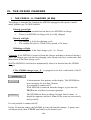
IV.
THE CR2000 CHARGER..........................................................................48
1.
V.
THE CR2000 - S- CHARGER (NI MH).........................................................................48
MAINTENANCE AND UPKEEP .............................................................49
1.
MAINTENANCE............................................................................................................49
2.
UPKEEP..........................................................................................................................51
VI.
OPERATING FAULTS .............................................................................52
VII.
TECHNICAL CHARACTERISTICS.......................................................53
-5-
VIII. LIST OF OPTIONS ...................................................................................57
1.
LIST OF PARAMETERS AND OPTIONS AVAILABLE IN THE
SOFTWARE OF THE MX2000 INSTRUMENTS ........................................................57
2.
IX.
LIST OF ACCESSORIES...............................................................................................57
APPENDICES ............................................................................................58
1.
PARAMETERS...............................................................................................................58
2.
CHARACTERISTICS OF THE CELL TYPES USABLE IN THE MX 2000 .............59
3.
ACCESSORIES ..............................................................................................................60
4.
SPARE PARTS ...............................................................................................................60
5.
PREPROGRAMMED GAS LIST...................................................................................61
6.
INTERNAL SENSITIVITY COEFFICIENTS LIST FOR MX2000 .............................62
7.
COMPLEMENTARY SENSITIVITY COEFFICIENTS TO BE PROGRAMMED ON
THE CHANNEL "OTHER GAS" FROM MX2000.......................................................63
8.
CONSUMABLE PARTS LIST.......................................................................................63
-6-
I.
P R E S E N T AT I O N
•
The MX2000 is a portable gas detector. It is one of the smallest 4-risk detectors on
the market. It can be equipped with a “high-luminance” LED display or a liquid
crystal display. In either case, it displays messages uncoded and in full.
•
It is used for the simultaneous detection of a maximum of 4 gases present in the
air, by means of 4 measuring cells specific to each of the gases which are to be
detected.
The gases concerned can be explosive (methane, natural gas, propane, butane,
etc.), toxic (carbon monoxide, hydrogen sulphide, etc.), or just oxygen.
The MX2000 has both pulsed and continuous alarms, both audible and visible, and
both common and specific to each channel.
•
Equipped with a remote manual or electric pumping system and a gas-injection
cap, the MX2000 is able to monitor the gas content in the most inaccessible places.
-7-
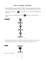
PRESENTATION IN DETAILS
DISPLAY
TOX 1
TOX 2
02
FLAM
FLASHING
COMMON
ALARM
FLASHING
COMMON
ALARM
ON / OFF
BUZZER
ENTER
(VALIDATION)
LIGHTING
DETECTION
CELLS
ADVANCE +
SHIFTING -
F i g. 1
-8-
MAKE-UP OF THE MX2000
The MX2000 is fitted with the following elements :
1) rear clip,
2) front panel,
3) display module,
4) explo cell (not shown),
5) electrochemical cells (toxics and oxygen),
6) cover,
7) power-supply pack,
8) main board,
9) external connectors (charging and computer connection),
10) the main housing,
11) switch keyboard,
12) buzzer,
13) gas injection cap,
14) 6 cover retaining screws.
F i g. 2
-9-
II.
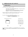
C O M MI S S I O N I N G I N T O S E R V I C E
1.
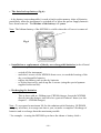
PO WER SU PPL Y
Several types of power supply are available :
- pack of four AA type alkaline batteries (R6, 1.5 V) placed in a battery
holder of plastic material (fig.5)
- pack of four A type or 4/5A nickel metal hydrure rechargeable
batteries (1.2 V) placed in a heat-shrink sleeve (fig.4)
The power-supply pack is connected to the main board by a plug-in connector.
The power-supply pack cannot be changed in a hazardous area.
In normal conditions of use, battery life is as follows :
§ 12 hours with a rechargeable battery pack
§ 15 hours with a dry battery pack
Rechargeable-battery pack
Dry-battery pack
Fig.4
Fig.5
Note: The instrument is certified for use in group I and IIc explosive atmospheres
only when it is fitted with dry or rechargeable batteries of a type recommended by the
manufacturer.
- 10 -
•
The data back-up battery (fig.6) :
- A dry battery (not rechargeable) is used to back-up the memory chips of historics,
particularly when the instrument is switched off or when the power-supply batteries
have been removed. The lifetime of the battery is 5 years.
Note: The lithium battery of the MX2000 is visible when the cell cover is removed.
Fig.6
•
Installation or replacement of the dry or rechargeable batteries (to be effected
only in a non-explosive atmosphere)
- switch off the instrument
- undo the 6 screws of the MX2000 front cover, to reach the housing of the
dry or rechargeable batteries
- replace the battery pack or the dry batteries
- re-fit the front cover, and do up the 6 screws (using the special spanner
supplied in the tool kit)
•
Recharging the batteries
- This is done with an Oldham type CR2000 charger. Insert the MX2000
directly into the charger, and leave for a period of about 5 hours (see the
chapter 3 : CR2000 charger).
Note : To saveguard a maximum life for the cadnium-nickel batteries, OLDHAM
company advocates, in average one time a year, to make a complete* discharge of
batteries and to recharge them the maximum possible.
* for example : in using the MX2000 up to have the alarme « battery fault ».
- 11 -
2.
•
M EA SU R EM ENT C EL L :
Presentation :
The cells used in the MX2000, which are a vital element of the instrument, must be
treated with great care. Mechanical shocks, excessive temperatures or just the entry
of water in the course of gas pumping, can be harmful to the quality of the
measurement, or may even ruin the cells in extreme cases..
The various cells (explo, O2, CO, H2S) are recognisable by their very special shapes
and by their clear and uncoded marking as illustrated by the CO and H2S cells (fig.7).
Physically, the cells will always be placed in the same manner. They cannot be
reversed (fig.8).
fig.7
explosimetric cell
oxygen cell
TOX cell
(CO or H2S)
•
Installation or replacement :
The cells are all of the plug-in type and can be reached when the cell cover is
removed, when they can be changed quickly and easily. This operation should be
carried out with care in a clean atmosphere :
- switch off the instrument
- undo the 6 securing screws of the front cover
- insert a new cell if necessary, or change a defective cell (refer to the
maintenance
- section for the use of menus)
- re-fit the front cover
fig.8
- 12 -
3.
•
R E M O T E S A M P L IN G
Presentation
The measurement or monitoring of gas concentrations prior to entering a cellar or any
relatively inaccessible areas can be effected by means of a remote-sampling probe.
•
The systems available
The systems can be equipped with a rigid or semi-rigid telescopic rod.
- manual - with intake bulb
- with electric pump
(See fig.11 for example)
Installation of the sampling system
The cap (fig.9) : position the cap on the cell cover of the MX2000. The cap clips into
the instrument, which enables it to be fitted rapidly and without the use of tools
(fig.10).
fig.9
•
Sampling system
Assemble the sampling system used, and then connect the pipe from the waterrejecting filter (2) to the entry of the cap (item 3 on fig.11).
- 13 -
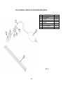
M A N U A L R E M O T E S A M P L I N G K I T W I T H R I G I D P R O B E M X2 0 0 0
N°
1
2
3
4
5
6
7
1
6
5
62
5
3
2
6
5
3
3
DESIGNATION
Ø5-Ø7Cristal pipe
TX12 ring
CX380 filter
Rigid probe
MX2000 calibration cap
MX21 filter adaptation
160CC pumping handle
7
2
4
FIG 11
- 14 -
REF. OFSA
6115864
6135902
6141141
6327871
6331119
6331114
6332211
•
Operation
Pumping and measurement:
With the pumping handle, it is necessary to pump at least 4 times to trigger an
alarm if the gas content so requires, and 8 times to obtain a reliable measurement.
Wait for the measurement to stabilise before accepting it. Measurement can be
over-estimated (explosive gases) or under-estimated (oxygen) during the pumping
process, due to the air movement.
With electric pumping (BP2000 for example...), press the On/Off button to start the
process, and wait for a few seconds before taking the measurement.
Removing the pumping system
Never forget to remove the gas entry cap after using the sampling system or after
calibration (fig.10).
THIS WILL GIVE RISE TO AN UNDER-ESTIMATE OF MEASUREMENTS,
WITH POTENTIALLY FATAL CONSEQUENCES FOR THE USER.
Fig.10
4.
gas entry cap
putting on MX2000
C A R R Y IN G T H E M X 2 0 0 0
Positioning the instrument
1/ The user is able to attend to his work, leaving the MX2000 to monitor the
atmosphere in which he is operating (the MX2000 is attached to his clothing by
means of a clip, or is carried about his neck by means of the carrying case strap).
2/ The user is able to perform one-off measurements by means of a manual or
electrical sampling system.
In order to be able to effect measurements correctly, the cells of the MX2000 must
always be clear of all obstructions. If this is not the case, the gas content can be
under-estimated, with fatal results for the user.
Even though the user is warned by means of powerful audio signal every 30 seconds,
it is vital that he is also in a position to watch the general and special alarm lights.
- 15 -
I I I . O P E R AT I ON
1.
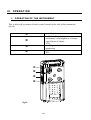
O P E R A T IO N O F T H E IN S T R U M E N T
This is achieved by means of tactile zones located on the side of the instrument
(fig.16).
•
- switching the instrument on and off
- validation (Enter)
- momentary extra-brightness of lamps
- cancellation of alarms
- YES
- scrolling
- numbering
- shift
- NO
‚
ƒ
„
•
‚
ƒ
„
fig.16
- 16 -
2.
S W IT C H IN G O N
2.1. Standard switch-on
The MX2000 is switched on by momentarily pressing the
key
A sound and light signal regularly indicates
correct operation of the instrument.
The following appear in succession on the display:
MX 2000
all lights come on
F 1.00
the version number of the software
TEST
self-test running
Then come successively the various channels programmed in the factory:
X-CO
GAS is the type of explosive gas programmed and detected.
X-H2S
X is the value of the detected measurement.
X-GAS
X- O2
If a channel is not in service, this is shown on the display.
GAS OFF
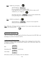
2.2. Switch-on with “gas selection” option
If the MX 2000 is equipped with this option, then switch-on of the instrument with
selection of the gas to be detected is achieved by simultaneously pressing the
and
- 17 -
keys.
The following then appear in succession on the display :
MX 2000
(momentarily)
then
METH %
then every time the
BUTANE
key is pressed :
and so on...
Confirm your choice by pressing:
The following then appears on the display:
F. X.XX
which is the version number of the internal software,
then
TEST
3.
followed by normal scrolling of the four channels.
S W IT C H IN G O F F
Press the
key continuously.
stop 3
The display then shows the count down
and goes off accompanied by an audio beep
stop 2
stop 1
Comment: it is not possible to switch off the MX2000 during its “TEST” phase.
In option, we can have the choice following : it will not be possible to switch off the
MX2000.
4.
L IG H T IN G
To increase the brightness of the display:
Press momentarily on the
key
The brightness of the display will return to normal after about 2 minutes.
- 18 -
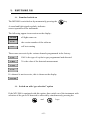
5.
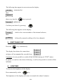
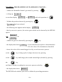
U S IN G T H E K E Y S
KEY
When this key is pressed momentarily for the first time will appear following the
preprogrammed options for example : "Rondier" list first name, the alternated time,
the date,…
20 : 22 : 42
or
Hrs mins secs
01 03 96
Date
Pressing a second time brings up:
ACC Volts
which is the voltage of the battery pack or dry batteries.
Pressing for a third time results in (for the channels switched on and for the options
chosen)
min GAS
alternating with
which is the minimum concentration of the explosible gas detected
X LEL
then in the next press
MAX GAS
which is the maximum concentration of the explosible gasdetected,
(in % LEL)
X LEL
•
then
MIN 02
the minimum oxygen concentration detected
X %
•
and
MAX 02
the maximum oxygen concentration detected (in %)
X %
- 19 -
•
Min CO
the minimum CO concentration detected (in parts per million)
X ppm
•
Max CO
the maximum CO concentration detected (in ppm)
X ppm
•
Min H2S
the minimum H2S concentration detected (in ppm)
X ppm
•
Max H2S
the maximum H2S concentration detected (in ppm)
X ppm
•
UEL CO
X ppm
(upper explosive limit) averaged measurement detected for CO
(in ppm)
•
UEL H2S
Averaged measurement detected for H2S (in ppm)
X ppm
- 20 -
•
LEL CO
(low explosive limit) averaged measurement detected for CO
X ppm
•
LEL H2S
averaged measurement detected for H2S
X ppm
Comment: Pressing the
key causes the brightness of the display to increase.
(1) If the instrument is equipped with the PATROL
function, the name of the first
selected zone appears first (see section on “patrol option”)
KEY
This is a shift key, or it is used to say “no”.
It is also used for scrolling or to say “no” in “patrol” mode
- 21 -
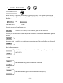
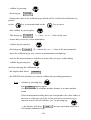
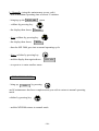
6.
M A IN T E N A N C E M O D E
- With the MX2000 in normal operation
- The accessible menus appear in using the key
(and/or code (0018))
- program = programming
- calib
= calibration
- chg cell = cell change
- self-adj = self-reset of cells (possible only after 15 minutes of operation)
- end
- Validate the selected menu by pressing the
key
THE PROGRAM MENU
- Do appear
program
- validate by pressing the
- this brings up:
chan CH4
- then successive presses on the
then
key
key bring up
chan O2
chan CO
then
chan H2S
- validate the wanted channel by pressing the
- 22 -
key
EXAMPLE : PROGRAMMING OF FLAMMABLE CHANNEL :
- validate the flammable channel (gas name) by pressing
ON
- to bring up
ON
we can thus display
or
OFF
with each operation of
- Validate the position choosen by pressing key
- If
ON
has been selected
- the following now appears on the display
meth %
- then by successive presses, the various gases which can be detected by the MX2000
appear.
meth LEL
etc
e.g.:
BUTANE
- validate the gas to be detected by pressing the
- the display then shows
al X.X
key.
al: the instantaneous explosive alarm threshold.
X.X: the value of the instantaneous threshold.
- choose the value of the wanted trigger level by several successive presses
on the
key to bring up the 1st digit, then move by pressing
on the
key and bring up the second wanted digit (decimal) by pressing
the
key
and finally validate everything by successive presses on the key
- the display then shows
YES NO ?
The MX2000 asks whether you wish to validate the preceding parameters.
- 23 -
if yes : validate by pressing the
then shows
key and the display
program
It is now possible to enter another menu by
pressing the
by displaying
key or to return to normal operation
END
Finally validate by pressing the
to normal operating mode.
key, and the MX2000 returns
if no : validate by pressing the
key,
when the display then shows
program
and it is now possible to re-start the parameter set-up, go into a menu or
return to normal operation (read the preceding sections).
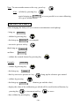
THE CALIB MENU
- bring up
calib
- validate by pressing key
- the following appears:
CHAN CH4
- then successive presses on key
then
(for example)
bring up
CHAN O2
CHAN CO
then
CHAN H2S
- validate the wanted channel by pressing key
Example
CHAN CH4
- validate by pressing
- this brings up
Butane
- then successive presses on key
bring up the reference gas wanted.
- 24 -
- validate by pressing
- this bring up
CG X.XX
- display the value of the calibration gas which will be used for the calibration, by
presses
on the
key to increment and on the
key to move.
- then validate by pressing key
- This brings up
: X.X.X.
( = zero, x.x..x. = value of the zero)
- ensure that you are in a clean atmosphere
- validate by pressing key
- this brings up
S :X.XX
(S = sensitivity x.x.x. = value of the measurement)
- inject the calibration gas (see section on maintenance and upkeep)
- wait for the measurement to stabilise to ensure that you get a valid reading
- validate by pressing key
and stop injecting the calibration gas
- the display then shows
YES NO?
- the MX2000 asks whether you want to validate the preceding parameters:
if yes : validate by pressing key
calib
and
appears again
It is now possible to calibrate another channel or to enter another
menu
If the measurement reading does not correspond to the value either of
the zero or of the gas used, due to low sensitivity or incorrect gas
injection and if you still validate “yes” by pressing key
→
the display will show
cell change (exhausted cell)
- 25 -
EXH
and you must then carry out a
Note: To enter another menu on the way, press key
if no : validate by pressing key
calib
again bringing up
or to go to another menu.
: it is now possible to re-start calibrating
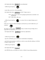
THE CHG CELL MENU
After changing the faulty cell (see section on maintenance and upkeep)
- bring up
CHG CELL
- validate by pressing key
- this brings up
CHAN CH4
(for example)
- successive presses on key
then bring up
and then
CHAN O2
CHAN H2S
- validate the wanted channel by pressing key
Example :
CHAN CH4
- validate by pressing key
- this brings up
Butane
- then by successive presses on key
bring up the reference gas wanted
- validate by pressing
- this brings up
CG X.XX
(calibration gas and the value)
- display the value of the calibration gas which will be used for the calibration, by
pressing key
to increment and key
- then validate by pressing key
- 26 -
to move
- the display then shows
0 adjust
(zero adjustment)
- validate by pressing key
- ensure that you are in a clean atmosphere
- the display then shows
XX : XX
and the 2 lamps come on
“XX” is the position of the 64-step digital potentiometer (automatic zero
adjustment)
“XX” is the value of the zero
- validate by pressing key
(fig.1).
as soon as the two common lamps go out
If the zero is still not stabilised (lamps are still on) but you still validate the “yes”
using key
the display will then show
repeat the zero adjustment.
bad adj
- the display then shows
S adj
and you return to the preceding state to
(sensitivity adjustment)
- validate by pressing key
- inject the calibration gas (see section on maintenance and upkeep)
- wait for the measurement to stabilise in order to ensure that the reading is valid (the
2 common lamps are out)
- validate by pressing key
- the display then shows
YES NO?
- the MX2000 asks you whether you wish to validate the preceding parameters.
- 27 -
if yes : validate by pressing key
chg cell
again bringing up
It is now possible to go to another menu.
If the signal has not yet stabilised (lamps still on), and you still
validate the “yes” (using key
)
bad adj
the display then shows
and you return automatically
to the preceding state to re-adjust the sensitivity.
if no : validate by pressing key
again bringing up
, and you can now repeat the
chg cell
calibration or enter another menu.
Note : When the cell change has been completed, if you want to enter another menu
(on the way), then press key
THE SELF-ADJ MENU
This is for automatic zero adjustment for all of the cells present in the MX 2000, even
including the switched-off channels (OFF).
a / when removed from the charger
When the MX2000 is removed from the charger after a charging time of more than
15 minutes, all lamps come on momentarily, together with a short audio signal, and
the display then shows
MX 2000
then
SELF ADJ
alternating with
several times
TEST
then finally
DONE
followed by normal cyclical display of the four channels.
- 28 -
b / Manually (using the maintenance access code)
- after a minimum operating time of about 15 minutes
- bringing up the SELF ADJ
menu
- validate by pressing key
- the display then shows
YES NO?
- if yes validate by pressing key
- the display then shows
DONE
- then the MX 2000 goes into a normal operating cycle
- if no : validate by pressing key
- and the display then again shows
SELF ADJ
- to repeat or to enter another menu
THE FINISH MENU
- bring up
END
by pressing
and if maintenance has been completed and you wish to return to normal operating
mode
validate by pressing key
- and the MX2000 returns to normal mode.
- 29 -
7.
A L AR M S
These are both visual (lamps/lights and display) and audible (fig.1)
•
GAS alarms
According to the programming and the type of gas, the “Gas alarms” can be triggered
when the following values are exceeded:
- instantaneous (on 4 channels)
- minimum (on oxygen channel only)
- maximum (on 4 channels)
- Short Term Exposure Limit (STEL) which is a rolling 15-minute mean
for each channel equipped with a TOX cell.
- Time Limit Value (TLV/TWA) which is a rolling 8-hour mean for each
channel equipped with a TOX cell.
Thus as soon as one channel goes above the pre-set thresholds , the MX2000 delivers
a pulsed sound signal. At the same time, the lamp of the channel concerned and the 2
common lamps blink.
Simultaneously, one or more alarm messages appear (O2 alarm, TLV, STEL, etc.),
together with the measurement value.
- 30 -
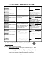
P U L S E D L I G H T A N D S OU N D A L A R M :
DISPLAY
AL 02
Alternating with the O 2
measurement
CAUSE
The over- or under-oxygenation
threshold has been exceeded
X 02
Alternating with the detected gas
measurement
The instantaneous threshold has
been exceeded
GAS is the type of gas detected
STEL GAS
X. GAS
GAS is the gas type detected
TLV GAS
Alternating with the detected gas
measurement
X. GAS
The STEL threshold is exceeded . - Sound alarms and common light
alarms (can be acknowledged*)
STEL is the limit exposure value - The corresponding lamp
continues to blink for as long as
during a given period (differs
the threshold continues to be
according to gas type)
exceeded
The TLV threshold has been
exceeded
The TLV is the mean exposure
value during a given period.
GAS is the gas type detected
disch.
- Sound alarms and common light
alarms (can be acknowledged*)
- The corresponding lamp
continues to blink as long as the
threshold remains exceeded
X. GAS
Alternating with the detected gas
measurement
- Sound alarms and common
light alarms (can be
acknowledged*)
- The “O2” lamp continues to
blink as long as the threshold
continues to be exceeded.
X is the value of the oxygen
measurement
AL GAS
REMEDY
The battery is starting to run
down. There remains about 30
minutes-worth of running time.
- Sound alarms and common light
alarms (can be acknowledged*)
- The corresponding lamp
continues to blink for as long as
the threshold continues to be
exceeded
- Sound alarms and common light
alarms (can be acknowledged*)
* The alarms are acknowledged by momentarily pressing the key
•
The FAULT alarms
The faults can be classified into 2 families
- those relating to the cells (out of range, exhausted cell, etc.). These
generate individual messages and a continuous sound alarm.
- those relating to the instrument itself ( battery discharged, loss of
memory, etc.). The corresponding fault message then appears on the
display. These generate a continuous sound and visual alarm.
- 31 -
C O N T I N U O U S S O U N D AN D VI S U A L A L A R M :
DISPLAY
disch.
EX RANGE
CAUSE
REMEDY
- Battery discharged: the
- Sound alarm (can be acknowledged)*
instrument is no longer usable - Visual alarm (cannot be
acknowledged): recharge the battery.
- The measuring range has
been exceeded.
Then
> 5.0 GAS
GAS is the gas type detected
- Sound and visual alarms (cannot be
acknowledged) in explosive gases: you
must leave the hazardous area and
switch the instrument off and on again.
- Sound and visual alarms (can be
acknowledged) in toxic gases and
oxygen, by momentarily pressing key
- Exit from the zone
- Cell faulty or missing
- Sound and visual alarms (cannot be
acknowledged)
- Switch off the instrument and install
or change the cell concerned
- Calibration unsuccessful
- Re-do the calibration: if the fault
persists, change the cell
GAS flt
GAS is the gas type detected
- Measurement too negative
GAS exh.
GAS CAL
FAULT
- Cell worn
- Sound and visual alarms (cannot be
acknowledged)
- Re-do the calibration
- Self-zero unsuccessful
- Sound and visual alarms (cannot be
acknowledged)
- Re-do the calibration
- Memory loss
- Lithium battery exhausted
- Sound and visual alarms (cannot be
acknowledged)
- Change the lithium battery, and if the
fault persists return the instrument to
the factory.
* The alarms are acknowledged by momentarily pressing key
- 32 -
8.
•
A C KN O WL ED G EM ENT O F A L AR M S
Acknowledgement of GAS alarms : by pressing key
momentarily
This consists of cancelling the pulsed sound signal and switching off the two
common alarm lamps. However, the alarm lamp of the corresponding channel will
continue to blink as long as the threshold continues to be exceeded.
•
Acknowledgement of fault alarms :
If a fault occurs, acknowledgement of the sound and visual alarms is not possible*.
Acknowledgement is automatic as soon as the fault has disappeared.
1) It is possible to acknowledge the visual and sound alarm, but only by exiting from
the hazardous area when the measuring range has been exceeded for toxic gases or
oxygen.
Example of a message in this case :
EX RANGE
alternating with
>5.0 GAS
where GAS is the gas type detected
N.B: When the fault alarm (continuous sound and visual alarm) is on, the 2 common
alarm lamps, and the sound alarm have priority over the pulsed GAS alarms, then in
this case only the channel lamp or the GAS alarm flashes.
2) It is possible to acknowledge the sound alarm when the
appears.
- 33 -
Disch.
message
9.
M E A S U R E M E N T R EA D IN G
The MX2000 can be equipped with either a red LED display or a liquid crystal
(LCD) display.
•
Immediate reading :
The gas content measured by each of the working cells is available on the display.
However, as the amount of information required by the bearer is greater than the
capacity of the display, the measurements are displayed successively and cyclically,
as follows:
X. GAS
X. 02
GAS is the gas type programmed
X is the value of the detected gas measurement
X. CO
X. H2S
•
If one or more channels are not working, the display then shows the name of the
gas followed by OFF.
For example:
•
02 OFF
Deferred reading :
When it is brought into service, the MX 2000 fitted with an RTC executes
continuous storage of readings in memory. It is thus possible to:
- read the histograms of the stored measurements and events at a later time (with the
aid of a PC, the COM2000 software and a CR2000 charger)
- or to print the histograms (with the aid of a printer, a PC and a CR2000 charger).
- 34 -
T H E “ P A T R O L ” OP T I ON
•
If the MX2000 is equipped with the “PATROL” function (initialised in the factory)
and if the instrument is now in normal operation, the first thing to appear on the
display, by pressing key ,
the factory.
is the name of the first zone pre-programmed in
Then, with each subsequent press on key
appear.
the names of the other zones
For example:
ZONE 1
ZONE 2
ZONE 3
etc.
•
During his round, the user must validate the detection zone (in order to store the
measurements taken therein), and this is required at each change of zone.
Example
ZONE 1
YES NO?
This ends the procedure
- 35 -
1 0 . D IS P L A Y B R IG H T N E S S
a / With an LED display
The brightness can be increased for about two minutes
by pressing key
or key
(to look up parameters such as the time, etc.) and in this case one can return to normal
brightness by pressing key
Comment: The display goes to its bright state whenever an alarm is triggered.
b / With the LCD display
The display can be back-lit for a period of about two minutes
by pressing key
or key
- 36 -
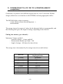
1 1 . C O N N E C T IO N T O A P C O R T O A P R IN T E R ( IB M - P C
c o mp a t i b l e )
Connection of a printer to the MX2000 requires the use of a PC and of the CR2000
charger (which acts as an interface to the MX2000) and using appropriate cables.
The MX2000 holds its data in memory :
- events (alarms, alarm acknowledgement...)
- measurements
The storage interval in respect of values for the historical tables is programmable, and
the following table gives the length of storage, depending on this interval.
Putting into memory (per channel) :
Maximum 2 frames and half
- guarantee storage : 1 frame and half
- measurements number per frame : 960
- lengh of storage : 960 times the interval time
The storage time is determined by the storage interval (see table below) :
minimum frame
length guarantee
24 minutes
48 minutes
2 hours
4 hours
12 hours
24 hours
48 hours
120 hours
240 hours
360 hours
Interval
1 second
2 seconds
5 seconds
10 seconds
30 seconds
1 minute
2 minutes
5 minutes
10 minutes
15 minutes
- 37 -
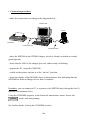
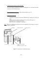
•
Connection procedure
- make the connections according to the diagram below :
COMPUTER
ORDINATEUR PC
MX2000
PRINTER
IMPRIMANTE
CR2000
COMPUTER/PC
Cordon liaison PC / IMPRIMANTE
COMPUTER/PC
Cordon liaison PC/CR2000
(1)
- place the MX2000 in the CR2000 charger, which is already switched on (steady
green light on)
- check that the LED of the charger goes red, either steady or blinking.
- prepare the PC, using the COM2000.
- switch on the printer, and put it to the “on line” position.
- check the display of the MX2000 shows a discontinuous line indicating that the
MX2000 has been on charge for less than 10 minutes.
Reminder: you can connect a PC or a printer to the MX2000 only during the first 10
minutes (discontinuous line)
Using the COM2000 program, in the historical maintenance menu, choose the
mode, and start printing.
printing
(for further details, look up the COM2000 section).
- 38 -
1 2 . U S IN G T H E C O M 2 0 0 0
T ab l e o f c o n t e n ts :
Connection
Characteristics
Maintenance
Analysis of faults
Histories
Setup
12.1.
CONNECTION
To make the connection between the MX2000 and the PC, proceed as follows :
- verify that the MX2000 is on - the MX2000 must be in its charger.
- check the charger: it must be connected to the power source, and connected to
the PC by the serial port,
- check that the communication options have been programmed correctly
(selection of serial port and of transmission speed),
- click on the Connection button.
Ø SELECTION OF THE SERIAL PORT
The MX2000 can be connected to any serial port, from COM1 to COM4.
The chosen serial port is stored, and used for the next COM2000 start-up.
Ø SELECTION OF THE TRANSMISSION SPEED
With the connection set up, the MX2000 and the PC can communicate at
speeds ranging from 1,200 bauds to 19,200 bauds, depending on the
hardware.
The transmission speed is stored, and used at the next COM2000 start-up..
- 39 -
12.2.
CHARACTERISTICS OF THE MX2000, current data
The data displayed on the Characteristics screen are read into the MX2000 and are
refreshed once every second for the four channels.
These data are:
- whether a channel is active or not
- the nature of the gas, and its scale,
- the instantaneous value,
- the upper and lower alarm thresholds for the oxygen channel,
- the min and max measurements,
- the LEV and MEV measurements for toxic channels,
- the date last calibrated,
- the date of the last cell change.
If a channel is faulty or switched off, all of its measurements are suppressed.
The characteristics can be saved in a check sheet, or they can be printed.
Ø CHECK SHEETS
These are used to hold the characteristics of the instrument at any given time (current
data).
These sheets are saved in a cumulative manner in files with a .CTR extension,
meaning that they are stored one after the other.
Movement in this file is achieved by:
- using the Check-sheet menu
- using Page up and Page down keys
- using the following buttons:
First sheet
Previous sheet
Next sheet
Last sheet
You move around within the sheet using the scroll bars.
- 40 -
12.3.
MAINTENANCE WORK
The Maintenance menu can be used for :
- calibration
- programming
- cell changing
Ø CALIB R ATION
Among other things, the maintenance menu is used for :
§ calibration of the explo channel,
§ calibration of the oxygen channel,
§ calibration of the toxic channels.
The operation can be halted at any stage.
§ CALIBRATION OF THE EXPLO CHANNEL
To carry out the calibration of the explo channel, proceed as follows :
- Check the concentration of the calibration gas proposed.
If you change this value, it will be stored for the next calibration.
If the displayed value suits you, click on the Next button.
- COM2000 displays the message “zero adjustment in progress...” and
displays the value for a check.
When the zero measurement stabilises and appears to be correct, validate
it by pressing the Next button.
The MX2000 will accept the value if it falls within an acceptable range.
- Then inject the calibration gas at the concentration indicated, as
requested by COM2000.
Press the Next button, and the sensitivity measurement is displayed in
the same way as for zero adjustment.
- Validate the operation by clicking the Ok button when the measurement
has stabilised.
- 41 -
§ CALIBRATION OF THE OXYGEN CHANNEL
To perform calibration of the oxygen channel, proceed as follows :
- Place the instrument in pure air, with COM2000 displaying the
sensitivity measurement of the instrument.
- Validate the operation by clicking on the Ok button when the
measurement has stabilised.
§ CALIBRATION OF THE TOXIC CHANNELS
To carry out the calibration of a toxic channel, proceed as follows :
- Check the concentration of the calibration gas proposed.
If you change this value, it will be stored for the next calibration.
If the displayed value suits you, click on the Next. button.
- COM2000 displays the message “zero adjustment in progress...” and
displays the value for a check.
When this zero measurement stabilises and when it appears to you to be
correct, validate it by pressing the Next button.
The MX2000 will accept this value if it falls within an acceptable range.
- Then inject the calibration gas at the concentration indicated, as
requested by COM2000.
Press the Next button. The sensitivity measurement is displayed in the
same way as for the zero adjustment.
- Validate the operation by clicking on the Ok button when the
measurement has stabilised.
Ø P ROGRAMM ING
Among other things, the maintenance menu is used for :
§ programming of the explo channel,
§ programming of the oxygen channel,
§ programming of the toxic channels.
For each channel, you are able to switch the channel on or off by clicking on the
corresponding box.
The data relating to this channel will no longer be displayed in the Characteristics
window.
- 42 -
§ PROGRAMMING THE EXPLO CHANNEL
To carry out programming of the explo channel, proceed as follows :
- switch the channel on or off by clicking the In Service box.
- select a gas from the scrolling list offered.
- if you select Other Gas, you must then enter the coefficient to be
applied, in the appropriate field.
- then enter the alarm threshold and validate the operation by clicking
on the Ok button.
§ PROGRAMMING THE OXYGEN CHANNEL
To carry out the programming of the oxygen channel, proceed as follows :
- switch the channel on or off by clicking on the In Service box.
- enter the upper and lower alarm thresholds, and validate the operation
by clicking on the Ok button.
§ PROGRAMMING THE TOXIC CHANNELS
To programme the « TOX » channel, proceed as follows :
- switch the channel on or off by clicking on the In Service box.
- select a gas from the scrolling list proposed.
- then enter the alarm threshold, and validate the operation by clicking
on the OK button.
- 43 -
Ø CHANGING A CEL L
The maintenance menu is used, among other things, for changing a cell in the
COM2000.
In a first stage, for all channels, the COM2000 requires a message of confirmation
before it will run the zero calibration procedures for the new cell.
When the cell is replaced and the request validated, the COM2000 begins the
changing a cell procedure.
12.4.
FAULT ANALYSIS
The events are indicated in priority order.
A scrolling list allows all the lines to be examined if the screen is too small.
The list of faults can be saved with the ODEF extension.
The following is a list of some faults which can occur :
FAULT
REMEDY
- during calibration, the zero is too shifted
→ repeat the calibration procedure
- during calibration, it is no longer possible to
measure at the limit of the scale.
→ repeat the calibration procedure
- following calibration, the cell is exhausted
→ replace the exhausted cell
- after self-adjustment, the measurement is too
shifted to allow for automatic correction
→ repeat the calibration procedure
- after changing the explo cell, the zero has been set → repeat the calibration procedure
incorrectly
- after changing the explo cell, the sensitivity has
been set incorrectly
→ repeat the calibration procedure
- the battery is low
→ recharge it
- 44 -
12.5.
HISTORIES
The histories are composed of frames, which themselves are composed :
- of the measurement part which indicates the gas concentration at any
time
- of events which may have happened during the frame (scale exceeded,
cell stopped, etc.)
You can look at the archived histories by entering the name of the file, with the HIS
extension, to be opened by COM2000.
You can then carry out the analysis of a frame.
§
ANALYSIS OF A FRAME
The histories can be viewed :
- either in text mode
- or in graphical mode
Here you must first choose one single frame for display, by selecting it either
using the mouse or by means of the scroll bar.
The scrolling list for frame selection then gives :
-
the serial number,
the setup of the instrument (for example : EXP, O2 , CO, H2S),
the start date and time
the end date and time.
When the frame has been chosen, and the mode established, validate the
operation by clicking on the Ok button.
- 45 -
§
THE TEXT MODE
When the histories are in text mode for the analysis of a frame, the dates, times,
and successive gas concentrations are shown in chronological order (the oldest
at the top).
A scrolling list is used to display the lines if the screen is too small.
§
THE GRAPHICAL MODE
When the histories are in graphical mode for the analysis of a frame :
- the title, the date and the time are shown at the top.
- the chronological order of events is shown on the abscissa (X axis), the gas
concentrations on the ordinate (Y axis).
- the gases are shown in colour.
The scales for the various gases are optimised automatically, in accordance with
the gas concerned, to achieve the best view.
By clicking on the icons of the various gases, you display or mask the
corresponding plot.
You are also able to select any particular part of the graph in order to zoom it.
- 46 -
12.6.
SETUP
You can modify the display mode (measurement or detection) and load the time
and/or the date of the MX2000.
The Code button enables you to alter the access code.
The Patrol button can be used to alter the patrol list.
Note : All modification of setup « purges » the histories.
§
CHANGING THE ACCESS CODE
After clicking the Code button in the Setup section, proceed as follows to alter
your access code :
- enter your current code (4 digits) and validate by pressing the Enter key,
- enter your new code and validate either by pressing the Enter key or by
clicking on the Ok button.
If you forget your code, please contact OLDHAM.
§
ALTERING THE PATROL LIST
After clicking the Patrol button in the Setup section, you can alter the order and the
content of the patrol list.
Any alteration of the patrol list will result in a purge of all histories.
To add a patrol, enter his name (8 characters maximum) then either click on the Add
button or press on the Enter key (30 patrols maximum).
To remove a patrol from the list, select the name, and either click on the Delete
button, or double-click it.
To reset the list, either press on the Del key, or click on the Delete all button.
To change the order of the list, click on the desired position and move it by keeping
the mouse button pressed (drag it). When you reach the chosen location, release the
mouse button and the moved position will be inserted there.
Validate the operation by clicking on the Ok button.
- 47 -
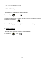
I V. T H E CR 2000 C H AR GER
1.
T H E C R 2 0 0 0 - S - C H A R G ER ( N i MH )
The charger is intended for charging the MX2000 equipped with a pack of nickel
metal hydride type (Ni MH) batteries.
1.Steady green light
•
The charger is switched on but there is no MX2000 on charge.
•
There is an MX2000 on charge, but it is fully charged.
2.Steady red light
•
The charger is in its fast charging cycle.
•
The current delivered is 120 mA for a period of 14 hours.
3.Blinking red light
•
The charger is in the float charge cycle (I ≅ 30 mA)
Comment: If the MX2000 is removed from the charger and then re-inserted, during a
cycle, the charger goes into the fast charging cycle (steady red) for a certain time, and
then returns to the float-charge cycle.
N.B The MX2000 is switched on automatically when it is inserted into the CR2000
charger.
4. The CR2000 charger type - S - is equipped, on its side, with female a Sub-D
connector for connection to a PC.
MX2000 display
--------
...................
A discontinuous line appears on the display. The MX2000 has
been on charge for less than 10 mins.
It is possible to connect a PC.
If the MX2000 is removed from the charger, it goes into the
TEST mode, and then to normal operation.
The MX2000 has been on charge for more than 10 mins. A
dotted line appears, and the 4 alarm LEDs come on successively
and cyclically.
It is not possible to connect the PC.
If after 20 mins on charge, the MX2000 is removed from the charger. It passes into
self-adjust mode, then to TEST and finally to the normal cycle.
- 48 -
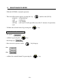
V.
MAI N T EN ANC E AN D U PK EEP
Important !
The only means of checking that the instrument's detection function is working
properly is the calibration performed with the help of a standard gas.
This "recommended" standard gas is specified on the label of the detector.
Nevertheless, some other standard gas may be used on referring to the table of
coefficients: Chapter VIII of this manual.
Hence, calibration mus be carried out :
1.
Every 6 months minimum
After an exposur at high gas concentrations
After more than one month storage with no use
After a module change
Following an instrument fault
M A IN T E N A N C E
A maintenance program built into the instrument enables you to alter the alarm
thresholds easily, and to carry out calibrations or cell changes without difficulty.
•
Self-adjustment
To be performed regularly, and especially after a cell change.
This procedure must be carried out in a clean atmosphere. Otherwise, the
sensitivity of the cell is liable to be defective.
Reminder : This takes place automatically whenever the MX2000 is removed
from the charger after 10 mins of charging.
•
Calibration
Calibration is the only way of checking the detection function, and is done
using a calibration gas.
Calibration must be carried out every three months and whenever the
instrument has been exposed to excessively-high concentrations of gas in use.
This also applies to an instrument which has been stored for a long period.
→
It is possible to carry out this procedure using the MX2000 alone
(calibration menu) and using the COM2000 program. The calibration menu
enables the cell to be calibrated automatically, during a cell change for
example, and when setting the zero and the sensitivity of the cell. Follow the
directions provided by COM2000 (help screens p.45).
- 49 -
•
Calibration procedures on the MX2000 :
For each channel, calibration consists of setting the zero in clean air and the
sensitivity with calibration gas.
•
Zero adjustment in clean air : follow the procedure on p. 28
•
Setting the sensitivity
- Clip the gas injection cap onto the MX2000 (fig.9 and fig.10) in the cell
zone.
- connect the tube from the calibration kit, and inject the gas at a
maximum rate of 60 litres per hour.
- then follow the “calibration” procedure.
Note : When the calibration procedure has been completed, do not forget to remove
the cap from the MX2000
MX2000
gas entry cap
vinyl hose
sampling gas outlet
sampling gas inlet
standart gas cylinder
manometer and pressure reducer
Fig.13 : Connection of calibration items
- 50 -
2.
U PK EEP
•
Re-charge the batteries or change the dry batteries regularly (outside of classified
areas).
•
The lithium battery should be changed every 3 to 5 years.
•
For users with the COM2000 software, this operation must be carried out by
authorised staff only.
•
Unscrew the cell-cover screws.
•
Remove the lithium battery, located alongside the tube, and insert a new battery *
•
Re-program the date and the time with the COM2000 software.
•
Re-mount the cell cover, and do up the screws.
•
For users without the COM2000 software, send the instrument to a distributor or
directly to our head offices.
* The instrument is certified for use in an explosive atmosphere only if it is equipped
with dry or re-chargeable batteries of a type recommended by the manufacturer.
- 51 -
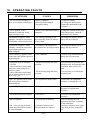
VI . OPER AT IN G F AU LT S
SYMPTOMS
- The screen shows nothing, if
there are no further audio beeps.
CAUSES
- Battery exhausted.
- Battery pack discharged.
- Instrument faulty
REMEDIES
- Change the battery.
- Re-charge the battery pack.
- Return the instrument to the
distributor.
FAULT appears, with a
continuous sound and visual
alarm cannot be reset
- Memory loss and lithium battery - Change the lithium battery and
exhausted.
if the fault persists, return the
instrument to the factory.
DISCHARGE appears, with a
common, continuous sound and
visual alarm, which can be reset.
- The battery is starting to run
down and only about 30 minutes
of use remain.
DISCHARGE appears, with a
common, continuous sound and
visual alarm (cannot be
acknowledged)
- The battery is discharged and
- Re-charge the battery pack or
the instrument is no longer usable change the dry batteries
- Re-charge the battery pack or
change the dry batteries.
GAS EXHAUST appears with a - Cells exhausted
sound and visual alarm (cannot be
acknowledged)
- Switch off the instrument and
change the cell concerned.
EX RANGE appears and then
> 5.0 GAS
- with a sound and visual alarm
(cannot be acknowledged) in
explosive gases.
- with a sound and visual alarm
(can be acknowledged) in toxic
gases and 0 2 gas
- The measuring range has been
exceeded
- It is necessary to exit from the
hazardous area, and switch off the
instrument, then switch it on
again.
- The measuring range has been
exceeded
- It is necessary to exit from the
hazardous area
GAS CAL appears with a sound
and visual alarm (cannot be
acknowledged)
- Self-adjustment unsuccessful
- Repeat the self-adjustment
procedure or change the cell
- IMPOSSIBLE appears
- Self-adjustment not possible
- Move to a clean atmosphere and
repeat the self-adjustment
procedure
- The measurements are negative
- Zero not set
- Perform a self-adjustment
procedure
GAS Deft appears
- Cell defective or missing
GAS : is the gas type detected.
Sound and visual alarm (cannot
be acknowledged)
- Calibration unsuccessful
- Measurement too negative.
- Insert or change the cell
concerned, after first switching
off the instrument
- Perform calibration once again.
If the fault persists, change the
cell
- 52 -
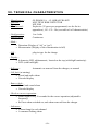
V I I . T EC HN I C AL C H AR ACT E RI ST IC S
- Manufacturer :
- Function :
- Type :
- Gas detected :
OLDHAM S.A. - 62 ARRAS FRANCE
MULTIPLE RISK DETECTOR
MX 2000
Explosive (25 gases pre-programmed; see the list in
appendices), O2 - CO - H2s (see table of cell characteristics)
- Configuration :
- Measurement :
1 to 4 risks
Continuous
- Mode :
•
Detection (Display of “ok” or “gas”)
• Measurement (Display of the concentration in full)
- Cell :
plug-in type for the change
- Display :
• 8-character LED, alphanumeric, located on the top (with high luminosity)
• LCD (with backlight)
- Self-zero :
Automatic on removal from the charger, or manual
- Cell fault (at starting)
• Visual and audio alarm
• Uncoded display
- Battery fault :
• Visual and sound alarm
• Uncoded display
- Check on correct operation :
• Audio signal every 30 seconds for the correct operation (adjustable
frequency)
• Self test when switched on, and when removed from the charger
- Indicators :
• 1 alarm lamp for each channel
• 1 common flashing alarm
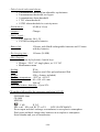
- 53 -
- Pulsed visual and sound alarms :
• 1 instantaneous threshold on adjustable explosimeter
• 2 instantaneous thresholds on oxygen
• 1 instantaneous alarm threshold
• 1 TLV alarm threshold
• 1 STEL alarm threshold as toxicity meter
- Sound alarm :
85 dB at 30 cm
- Outputs :
Charger
- Power supply :
• 4 dry batteries, R6 1.5V
• 1 Ni MH rechargeable batteries
- Battery life :
12 hours with NimH rechargeables batteries and 15 hours
with dry batteries
- Re-charging time :
14 hours (Ni MH)
- Miscellaneous :
• Operation by keyboard, 4 tactile keys.
• Charger: 220 V AC single phase, or 12 V DC
• Maintenance menu
- Sealing :
IP 66
- Case :
Stainless-steel fibre polycarbonate-filled
- Weight :
450 g (battery included)
- Working temperature : -20°C to + 45.0°C
- Dimensions :
80 x 150 x 40 mm
- Volume :
480 cm 3
- Maximum relative humidity : Up to 95%
CE marking followed by the european regulation 94/9/CE
OLDHAM Arras
CE 0080
MX2000
I M1
II 2 G
EEx ia d I EEx ia d IIC T3 or T4
LCIE 02ATEX6054X
Do not open and don't recharge accumulators in an explosive atmosphere.
Don't open and don't change druy batteries in an explosive atmosphere.
Serial number and year of construction
- 54 -
Note : Under the using ATEX group II, the temperature classification T3 or T4
depends the instrument power supply. When an instrument is fitted with dry
batteries or with an rechargeable battery-pack indicated T4, the temperature
classification will be T4. With other types of pwer, the temperature
classification will be T3.
CE marking followed by the european regulation CEM 89/336/CEE
Métrology :
Testing of characteristics made by DMT ( Deutsche Montan Technologie), report n°
PFG – Nr – 41300298 :
- Followed by EN 50054 and 50057 scale 0 à 100 % LEL CH4
- Followed by EN 50104 scale 0 to 25 % oxygen,
- Followed by Din T017 scale CO and H2S
Approvals :
CSA : N° LR 104516 C22.2 N°152 Ex ia T4 CLASS I, Groups A, B, C, D
GOSSTANDARD : ROSS FR.GB.05.B00597 PO Ex iasI 1 Exibd IIC T4 X
- AFAQ
- CSA
ISO 9001
Class I – Group A, B, C et D
- 55 -
- 56 -
V I I I . L I ST OF O PT I ON S
1.
L IS T O F P A R A M ET E R S A N D O PT IO N S A V A IL A B L E IN T H E
S O F T W A R E O F T H E M X 2 0 0 0 IN S T R U M E N T S
Options
STEL / TLV (TWA) : allows storage or not of the STEL and TLV.
Detection : normal or Gas operating mode.
For the next two options, the MX 2000 must have been operating for at least the time
given by the stabilisation variable. This allows a self-zeroing to be carried out on
cells which have been operating for some time.
Self-zero on removal from charger : if this option is programmed, a self-zero is
done automatically when the instrument is removed from the charger.
Manual Self-zero : allows the user to do a self-zero on the instrument itself.
The user must go into the maintenance mode on the MX 2000 in order to gain access
to this option.
Identification : this option validates the patrol function. If this option is
validated, then the current patrol can be altered by pressing key
once.
Changing the current patrol creates a new record frame in the histories.
Switch-off disabled : this option prevents the instrument being switched off, unless
any doubt is removed or switch-off is enabled again.
Time / date : gives the time in hours, minutes and seconds.
gives the date in days, months and years (the last 2 digits) (only the MX 2000 with
internal Real-Time Clock).
Location list : list of names of the zones visited in the“patrol” function (memory
space for 30 names of 8 characters).
2.
L IS T O F A C C E S S O R IE S
§
§
§
§
§
§
- leather case
- key « allen »
- gas introduction nozzle
- computer interface
- transformer
- charger
6121528
6145737
6331119
6315831
6111189
6511140
- 57 -
I X. APPEN D I C ES
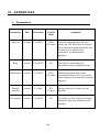
1.
P a r a me t e r s
Parameter
Unit
Excursion
Typical
value
Comment
Time-out
second
1 to 65535
600 s
(10 mins)
From the moment when the user
places the MX 2000 into its charger,
this is the time during which the user
is allowed to connect to the
instrument, for maintenance
purposes.
Beep
second
2 to 65535
30 s
Stabilisation
second
1 to 65535
600 s
(10 mins)
Storage
interval
second
1 to 900
60 s
(1 min)
Test period
second
1 to 65535
15 s
- 58 -
The interval separating two
instrument correct operation beeps.
Minimum running time of the
instrument before a self-zero can be
done (manual or on removal from the
charger).
Storage interval of values for the
histories
At switch-on, this is the time during
which the min, max alarms are not
enabled.
2.
C H A R A C T E R IS T IC S O F T H E C E L L T Y P E S U S A B L E IN
TH E MX 2000
Explo
O2
CO
H2 S
Standard range
100% LEL
30% vol
500 ppm
100 ppm
Minimum
detectable
Accuracy
Zero drift
Response time
Lifetime
Guarantee
1% LEL
0.1% vol
1 ppm
1 ppm
< 3%
< 3%
20 s
48 month
12 month
< 0.3% vol
< 0.1% vol
< 10 s*
18 month
12 month
< 5%
< 2%
30 s
48 month
12 month
< 5%
< 2%
30 s
48 month
12 month
* time to activate the alarm at 18% vol.
- 59 -
3.
A C C E S S O R IE S
Name
References
EXPLO cell
O2 cell
CO cell
H2S cell
Gas injection cap
Ni MH. S charger
Carrying bag
Hexagonal male spanner
PC lead
Gas calibration kit (in 6.8 l)
4.
6313 530
6313 531
6313 535
6313 536
6331 119
6511 141
6121 528
6145 737
6116 026
Air Zero
Methane 2.5%
CO 300 ppm
H2S 30 ppm
6128 746
6128 741
6128 748
6128 786
SPA R E PA RT S
Name
Reference
Cover screws
Cell cover
Housing
LED circuit display
Main circuit, “RTC” version
Main circuit, “STD” version
Lithium battery
Dry battery support block
LR6 dry batteries
Keyboard
Front panel
6336 973
6123 545
6121 269
6451 375
6451 380
6451 374
6111 174
6352 346
6111 147
6122 432
6122 433
- 60 -
5.
P R E P R O G R A M M E D G A S L IS T
•
•
•
•
•
•
•
•
•
•
•
•
•
•
•
•
•
•
•
•
•
•
•
•
% methan
LIE methan
butan
propan
natural gas
ethylen
pentan
hexan
propylen
acetylen
ethanol
aceton
propylen oxyd
ethylen oxyd
isobutan
dimethyl (dymethylether)
ethyl acid (ethyl acetat)
2 - butano (2 - butanone)
isopropan (isopropanol)
xylen
toluen
super es (1 - 3 butadien)
hydrogen
other (other gas)
- 61 -
6.
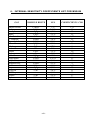
IN T E R N A L S E N S IT IV IT Y C O E F F IC IE N T S L IS T F O R M X 2 0 0 0
GAZ
ethylen Acetat
Aceton
Acethylen
Butan
1,3 - Butadien
2 - Butanon
Dymethylether
Ethanol
Ethylen
natural Gas
Hexan
Hydrogen
Isobutan
Isopropanol
ethylen Oxy,
propylen Oxy,
Pentan
Propan
Propylen
SP95Super
Toluen
Xylen
FORMULE BRUTE
LEL
COEFFICIENTS CH4
C4H8O 2
C3H6O
C2H2
C4H10
C4H6
C4H8O
C2H6O
C2H6O
C2H4
CH4
C6H14
H2
C4H10
C3H8O
C2H4O
C3H6O
C5H12
C3H8
C3H6
/
C7H8
C8H10
3%
2.15 %
1,5 %
1,5 %
1.4 %
1,8 %
3,0 %
3,3 %
2,7 %
5%
1,2 %
4,0 %
1.5 %
2,15 %
2,6 %
2,3 %
1,4 %
2,0 %
2,0 %
1,1 %
1,2 %
1,0 %
1,35
1,3
1,1
1,5
1,25
1,5
1,55
1,1
1
1,1
1,6
0,55
1.5
1,3
2,1
2
1,35
1,2
1,1
2,3
1,7
2.6
- 62 -
7.
C O M P L E M E N T A R Y S E N S IT IV IT Y C O E F F IC IE N T S T O B E
P R O G R A M M E D O N T H E C H A N N E L " OT H E R G A S " FR O M
MX2 0 0 0
GAS
General
formula
LEL
UEL
Vapour
density
Coef /
CH4
Calib.gas
recommended
Benzene
C6H6
1.2 %
8%
2.7
2.7
But/Prop
Cyclohexanone
CH2 (CH2)4C
1.3 %
9.4 %
3.4
3.2
But/Prop
Petrol ("super")
Mixture
1.3 %
6%
>2
2.1
But/Prop
Ethane
C2H6
3.0 %
15.5 %
1.04
1
L.P.G.
Prop + But
1.65 %
≅
9%
1.85
1.48
But/Prop
Diesel
Mixture
0.6 %
≅
6%
>4
5
But/Prop
Kerosene (JP4)
C10 – C 16
0.7 %
5%
>4
7.5
But/Prop
Methanol
CH3 OH
5.5 %
44 %
1.1
0.8
Methylamine
CH3NH2
4.9 %
20.7 %
1.1
1.05
Octane
C8H18
1.0 %
6%
3.9
1.7
But/Prop
Styrene
C8H12
1.1 %
8%
3.6
2.5
But/Prop
White spirit
Mixture
1.1 %
6.5 %
>2
3
But/Prop
8.
C O N S U M A B L E P A R T S L IS T
Designation
Reference
- Ni mH pack battery
- dry battery
- oxygen cell
- explo cell
- CO « CY » cell
- H2S « CY »cell
6311079
6111147
6313531
6313530
6313535
6313536
CAUTION : Consumable parts will have to be garanted from OLDHAM S.A. origin,
otherwise, equipment safety will not be assured.
- 63 -
Please detach and destroy this slip after having commited your code
to memory
"
Your secret code is :
- 64 -
0018
OLDHAM SA - GAS DETEC TION D IVISION
LIMITED W ARRAN TY
As per sales conditions
RELIABILITY - C ONTROLS
Your satisfaction is our primary concern. This means our equipment and our technical departments must be reliable, and
the quality of our production is essential to achieve that reliability. Quality is ensured by extremely strict verifications
carried out during production, at the end of manufacture and before shipment. (All shipped equipment is configured to
meet your requirements). These steps help to save time during equipment start-up and avoid additional costs.
START-UP
Entrusting the start-up of your equipment to our expert technicians gives you the guarantee of additional safety.
F IELD SER VIC ING
Our AFTER-SALES SERVICE technicians are ready to service your equipment very quickly on your site. This
performance is made possible by the efficient network of our branches throughout the world.
For any specific technical question, please contact our Service Responsible person, Mr. MIGUEL RIESGO, 00
33 3 21 60 80 86.
F ACTORY REP AIRS
For any problem which cannot be solved in the field, a team of SPECIALIZED TECHNICIANS is on hand to ensure
the quick repair of your equipment sent to our plant in ARRAS, France. In this way, OLDHAM SA undertakes to keep
the downtime for your equipment to a minimum.
- 65 -
MAINTENANC E CON TR ACT
REGULAR MAINTENANCE IS NEEDED to ensure that your equipment meets the stipulated performance levels, as
well as to guarantee the safety.
OLDHAM SA CAN offer you MAINTENANCE CONTRACTS.
TR AIN IN G
OLDHAM SA has a fully-equipped TRAINING Department : a number of engineers specialized as instructors,
conference rooms, equipment available for practical exercises, computer equipment, display equipment, etc..
You are thus assured that your personnel will receive all the TRAINING REQUIRED to use our equipment and
perform first-level maintenance. This training can cover our entire product range.
OLDHAM SA organizes SCHEDULED TRAINING SESSIONS (1 week) at the head office in ARRAS. Special
training programs can however be set up at the head office or on your site.
QU ALITY
With the assurance that we comply with ISO STANDARDS, our users can have complete confidence in OLDHAM
SA QUALITY.
AD VANTAGES
OLDHAM SA is represented in major countries worldwide with sales and service centers.
OLDHAM SA uses all the modern means of communication, such as e-mail, fax and Internet.
OLDHAM SA is always present at large trade events, i.e. regional, national and international EXHIBITIONS.
- 66 -