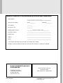
1
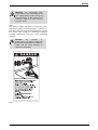
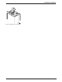
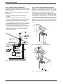
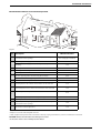
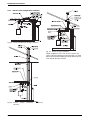
GWH 345/450 ESR
Temperature Modulated with Electronic Ignition
Suitable for heating and recirculating potable water
6 720 607 909 US (2008.02) JS
GWH-345/450-ESR-N - Natural Gas
GWH-345/450-ESR-L - Liquefied Petroleum (LP) Gas
Warning: If the information in this manual is not
followed exactly, a fire or explosion may result
causing property damage, personal injury or death.
Do not store or use gasoline or other flammable
vapor and liquids in the vicinity of this or any other
appliance.
What to do if you smell gas
Improper installation, adjustment, alteration,
service or maintenance can cause injury or
property damage. Refer to this manual. For
assistance or additional information consult a
qualified installer, service agency or the gas
supplier.
In the Commonwealth of Massachusetts this
product must be installed by a licensed plumber or
gas fitter.
• Immediately call your gas supplier from a neighbor’s
phone. Follow the gas supplier’s instructions.
Upon completion of the installation, these
instructions should be handed to the user of the
appliance for future reference.
• Close gas valve. Open windows and doors, and
evacuate the building.
• Do not try to operate any appliance.
• Do not touch any electrical switch; do not use any
phone in your building
• If you cannot reach your gas supplier, call the fire
department.
• Installation and service must be performed by a
qualified installer, service agency or the gas supplier.
Index
Index
1
Warning
2
2
2.1
2.2
2.3
2.4
2.5
2.6
2.7
Appliance details
Features
GWH-345/450-ESR Specifications (Technical data)
Unpacking the GWH-345/450-ESR heater
General rules to follow for safe operation
Dimensions and minimum installation clearances
Applications
Water quality
4
4
4
5
6
7
8
9
3
3.1
3.2
3.3
3.4
3.5
3.6
3.6.1
3.6.2
3.6.3
3.6.4
3.6.5
3.6.6
3.6.7
3.7
3.8
3.9
3.10
3.11
Installation instructions
Introduction
Proper location for installing your heater
Heater placement and clearances
Mounting installation
Combustion air requirements
Venting
Vent material and specifications
Vent connections and air inlet restrictors
Condensate drain requirements
Room sealed installation (Twin pipe)
Vertical terminations
Horizontal terminations
Exhaust vent configuration examples
Gas piping & connections
Measuring gas pressure
4
4.1
4.2
4.3
4.4
4.5
4.6
4.7
4.8
Operating instructions
Initial filling instructions
For your safety read before operating your water heater
Startup instructions
Power
Recirculating water temperature
Temperature and hot water flow
Freeze protection
Electrical diagram
27
27
27
27
28
28
28
28
29
5
5.1
Maintenance and service
Service mode
30
30
6
Troubleshooting
32
7
GWH-345/450-ESR Functional scheme
34
8
8.1
8.2
8.3
Interior components diagram and parts list
Interior components
Components diagram
Parts list
35
35
36
37
9
Protecting the environment
38
10
Ten Year Limited Warranty
39
2
10
10
10
10
10
11
13
13
14
17
17
18
18
21
22
24
Checking restrictor plate size by measuring CO2 level value 24
Water connections
25
Electrical connections
25
1
Warning
For your safety
Do not store or use gasoline or other flammable,
combustible or corrosive vapors and liquids in the
vicinity of this or any other appliance.
Warning: Carefully plan where you
install the heater. Correct combustion
air supply and flue pipe installation are
very important. If a gas appliance is not
installed correctly, fatal accidents can
result from lack of air, carbon monoxide
poisoning or fire.
Warning: Exhaust gas must be vented
to outside using 3" single wall sealed
stainless steel vent pipe suitable for
category III vent systems and
temperatures up to 480°F. Vent and
combustion air connector piping must
be sealed gas-tight to prevent
possibility of flue gas spillage, carbon
monoxide emissions and risk of fire,
resulting in severe personal injury or
death.
Warning: Place the recirculating water
heater in a location where water leaks
will do NOT DAMAGE adjacent areas
or lower floors.
Warning: Field wiring connections and
electrical grounding must comply with
local codes, or in the absence of local
codes, with the latest edition of the
National Electric Code, ANSI/NFPA 70,
or in Canada, all electrical wiring must
comply with the local codes and the
Canadian Electrical Code, CSA C22.1
Part 1.
Warning: Shock hazard line voltage is
present.
Before
servicing
the
recirculating water heater, turn off the
electrical power to the recirculating
water heater at the main disconnect or
circuit breaker. Failure to do so could
result in severe personal injury or death.
6 720 607 909
Warning
Warning: The recirculating water
heater must be disconnected from the
gas supply piping system during any
pressure testing of that system at test
pressures equal to or more than 0.5
psig (14” W.C.).
FCC:
This device complies with Part 15 of the FCC rules.
Operation is subject to the following two conditions: (1)
This device may not cause harmful interference, and (2)
this device must accept any interference received,
including interference that may cause undesired
operation.
Caution:
Any
changes
or
modifications not expressly approved
by the party responsible for compliance
could void the user’s authority to
operate the equipment.
Fig. 1
6 720 607 909
3
Appliance details
2
Appliance details
2.1
Features
Temperature Control
Selection range: 115°F (45°C) - 190°F (90°C)
Parts
• Sealed combustion burner.
Gas Requirement
Safety
Gas connection (inches) - ¾”
• Ionization flame sensor
Inlet gas pressure under operation (with a high hot
water flow rate)*
• Over temperature protection.
High quality materials for long working life
• Copper heat exchanger
• Compact space saver: mounts on a wall with
supplied bracket.
Features
• Propane: 11” - 14” water column
• Natural Gas: 5.5” - 8” water column.
* To measure gas pressure, see Measuring Gas
Pressure, chapter 3.8.
Venting
• LCD screen to display temperatures, burner
operation and error codes
3" AL 29-4C single wall sealed stainless steel vent
pipe.
See chapter 3.6 for Venting.
• On/Off button and separate temperature controls for
domestic water heating and recirculating water
Water
• Reset button
• Failure codes for diagnostics and repair
• Freeze prevention cycle.
• Hot water connection - ¾” NPT
• Cold water connection - ¾” NPT.
Combustion
• NOx ≤ 100 ppm
i
2.2
BOSCH is constantly improving its
products, therefore specifications are
subject to change without prior notice.
GWH-345/450-ESR Specifications
(Technical data)
• CO ≤ 250 ppm
• CO2 level (see table 8 for correct restrictor
dimension).
Dimensions
• Depth (in): 11 ¾” (300 mm)
Approved in US/Canada
• Width (in): 15 ¾” (400 mm)
Capacity
• Height (in): 27 ½” (700 mm)
GWH345 Maximum flow rate: 3.5 GPM (13 l/min) at a
45°F (25°C) rise.
GWH450 Maximum flow rate: 4.5 GPM (17 l/min) at a
45°F (25°C) rise.
Maximum output
GWH345 - 77,900 Btu/h (22.8 kW)
GWH450 - 98,400 Btu/h (28.8 kW)
Maximum input
GWH345 - 95,000 Btu/h (27.8 kW)
GWH450 - 120,000 Btu/h (35.1 kW)
Efficiency in %
GWH345 Combustion efficiency: 82%
GWH450 Combustion efficiency: 81%
Min. Output
GWH345 - 23,900 Btu/h (7 kW)
GWH450 - 35,500 Btu/h (10.4 kW)
• Weight: 47 pounds (21 kg).
Gas types
Natural Gas.
Liquid Propane.
The appliance is not field convertible.
Voltage
120 V AC (50/60 Hz)
Amperage
Idle - 40 mA
Operation - ≤ 1.5 A
Noise
≤ 50 db (A)
Safety devices
• Flame failure device (Ionization flame control)
• Overheat prevention (temperature limiter)
• Pressure switch (blocked vent protection).
4
6 720 607 909
Appliance details
Water resistant
IP X4 (protection against water drops)
2.3
Unpacking the GWH-345/450-ESR
heater
This heater is packed securely.
The box includes:
To remove front cover
i
The front cover is secured with two
screws to prevent unauthorized access.
Always secure the control panel and front
cover with these screws.
B Loosen the two Philips head screws located as
shown in fig. 2.
• Wall-mounted gas fired recirculating water heater
• Bracket and screws for wall hanging the heater
• Exhaust vent adaptor (with 4 screws and gasket
provided)
• Combustion air inlet adaptor (with 4 screws and
gasket provided)
• Installation manual
• Product registration card
• Energy Guide label
Fig. 2
• Pressure relief valve
B Pull control panel outwards and then pull it
downwards (Fig. 3).
• Inlet air restrictors
– GWH 345 ESR N: Ø38/40/42
– GWH 345 ESR LP: Ø38/40/42
– GWH 450 ESR N: Ø44/47/50/55
– GWH 450 ESR LP: Ø47/50/55/60
Screws
Front cover
Do not lose this manual. Please complete and return
the enclosed product registration card.
Before installing the unit, be certain you have the
correct heater for your type of Gas - Propane or
Natural Gas. Identification labels are found on the
shipping box, and on the rating plate which is located on
the right side panel of the cover.
Low voltage
access cover
Control panel
Fig. 3
Service position to access water and electric
connections
B Lift front cover upward and remove.
The GWH-345/450-ESR is not approved or
designed for:
• Manufactured (mobile) homes, RV's or boats
• Outdoor installation
• Combination venting with other appliances
• Closed loop heating applications.
6 720 607 909
5
Appliance details
2.4
General rules to follow for safe
operation
1. You must follow these instructions when you install
your heater. In the United States: The installation
must conform with local codes or, in the absence of
local codes, the National Fuel Gas Code ANSI
Z223.1/NFPA 54.
In Canada: The Installation must conform with CGA
B149.(1,2) INSTALLATION CODES and /or local
installation codes.
2. Carefully plan where you install the heater. Correct
combustion air supply and vent pipe installation are
very important. If not installed correctly, fatal
accidents can be caused by lack of air, carbon
monoxide poisoning or fire.
11.The heater must not be installed in an unheated area
where temperatures will reach 36°F or lower. If the
heater is left in an area susceptible to such
temperatures, drain the unit and disconnect from
electrical supply. See Chapter 4.7 for additional
freeze prevention information.
12.In areas where water supply has a high mineral
content, a water softener is strongly recommended.
A water softener is required if the water hardness
exceeds 6 grains/gal (103 mg/l) calcium carbonate.
Damage to the water heater resulting from hard
water/scale deposits will not be covered under
warranty.
3. When the unit is installed indoors with ROOM
SEALED (twin pipe) combustion air and venting, it is
permitted to be located in bathrooms, bedrooms and
occupied rooms that are normally kept closed. See
chapter 3.6. If the unit will be installed indoors and
use indoor combustion air, the place where you
install the heater must have enough ventilation. The
National Fire Codes do not allow UNSEALED gas
fired water heater installations in bathrooms,
bedrooms or any occupied rooms normally kept
closed. See chapter 3.2 and 3.5.
4. You must vent your heater. See chapter 3.6 Venting.
5. The appliance and its gas connection must be leak
tested before placing the appliance in operation. The
appliance must be isolated from the gas supply
piping system by closing its individual manual gas
shutoff valve (not supplied with heater) during any
pressure testing at pressures in excess of ½ Psig
(3.5 kPa).
6. Keep water heater area clear and free from
combustibles and flammable liquids. Do not locate
the heater over any material which might burn.
7. Correct gas pressure is critical for the optimum
operation of this heater. Gas piping must be sized to
provide the required pressure at the maximum output
of the heater, while all the other gas appliances are in
operation. Check with your local gas supplier, and
see the section on connecting the gas supply.
8. Should overheating occur or the gas supply fails to
shut off, turn off the gas supply at the manual gas
shut off valve, on the gas line. Note: manual gas
shutoff valve is not supplied with the heater.
9. Do not use this appliance if any part has been
underwater. Immediately call a qualified service
technician to inspect the appliance and to replace
any part of the control system and any gas control
which has been underwater.
10.Failure to install heater correctly may lead to unsafe
operation and void the warranty.
6
6 720 607 909
Appliance details
2.5
Dimensions and minimum installation clearances
Fig. 4
Dimensions
1
2
3
4
5
6
7
8
9
Combustion air inlet adapter (right side only)
Exhaust adapter with CO2 measuring point
Front cover
On/Off button
Reset button
Recirculating water temperature selector
LED - (ON) warning light (blinks when in error lock out)
Domestic hot water temperature selector
Mounting plate
Fig. 5
Minimum clearances
Model GWH-345/450-ESR
TOP
12”
FRONT (B)
4”
BACK
0”
SIDES
½”
BOTTOM
12”
Table 1 Minimum clearances
6 720 607 909
7
Appliance details
2.6
Applications
Caution: the water heater which will be
used to supply potable water shall not
be connected to any heating system or
component(s) previously used with a
nonpotable water heating appliance.
Introduction
The application designs provided in this manual are general guides to be used when installing this recirculating water
heater.
Pump Sizing
Required PS pumps are Taco 007 Bronze or Grundfos 15-42B. PZ pumps should be sized by a professional plumbing contractor based on the specific application.
Caution: Do not overpump the heater.
Maximum 5 gpm water flow permitted
through the heater.
Instantaneous water heater (direct tank load design)
Note: maximum amp draw:
1,5A. Do not connect
additional pump to the
appliance but use a relay panel
if powering multiple pumps.
Fig. 6
Front cover
Low voltage
access cover
Control panel
Fig. 7
8
Service position to access water and electric
connections
6 720 607 909
Appliance details
Pressure drop curves
Note: Flow above 6 GPM is not permitted.
50 feet of head
GWH 345 ESR
Inlet pressure
40 feet of head
30 feet of head
20 feet of head
10 feet of head
0 feet of head
0 GPM
1 GPM
2 GPM
3 GPM
4 GPM
5 GPM
6 GPM
5 GPM
6 GPM
water flow rate
Fig. 8
GWH 345 ESR
50 feet of head
GWH 450 ESR
Inlet pressure
40 feet of head
30 feet of head
20 feet of head
10 feet of head
0 feet of head
0 GPM
1 GPM
2 GPM
3 GPM
4 GPM
water flow rate
Fig. 9
GWH 450 ESR
2.7
Water quality
Water quality can have an impact on appliance performance and appliance longevity, and may not be covered by the
manufacturer's warranty.
For water analysis data call your local water department. If on a well system, have well water analyzed periodically. If
water quality is exceeding one or more of the values specified below, Bosch recommends installing a water conditioner or softener.
Description
pH
TDS
(Total
Dissolved
Solids)
Total
hardness
Aluminum
Chlorides
Copper
Iron
Manganese
Zinc
Max.
Levels
pH
range
mg/l or
ppm
mg/l or
ppm
mg/l or
ppm
mg/l or
ppm
mg/l or
ppm
mg/l or
ppm
mg/l or ppm
mg/l or
ppm
6.5-8.5
500
100 (6
grains)
0.2
250
1.0
0.3
0.05
5.0
Table 2 Venting Specifications
6 720 607 909
9
Installation instructions
3
Installation instructions
3.1
Introduction
Please follow these instructions. Failure to follow
instructions may result in:
• Property damage or personal injury
• Improper operation
• Heater damage
• Loss of warranty.
Please contact Bosch Water Heating with any
questions.
3.2
Proper location for installing your
heater
Carefully select the location of the water heater. For
your safety and for proper heater operation, you must
provide combustion air to the heater and a proper
exhaust vent system.
Follow the guidelines below:
B 1. Locate the heater where venting, gas and
plumbing connections are feasible and convenient.
B 2. The hot water lines should be kept short to save
energy. Centrally locating the water heater is best. It
is always best to have hot water lines insulated.
3.3
The GWH-345/450-ESR is design certified for
installation on a combustible wall (see 3.4 Mounting
installation) provided the floor covering below the
heater is noncombustible. For installations in an alcove
or closet, maintain the minimum clearances to
combustible and non-combustible materials listed
below. See also fig. 5.
A. Top 12 inches (305 mm)
B. Front 4 inches (100 mm)
C. Back 0 inches
D. Sides ½ inches (12 mm)
E. Bottom 12 inches (305 mm)
Clearances from any exhaust vent pipe are dependent
upon the clearance requirements of the stainless steel
vent pipe manufacturer. Single wall sealed stainless
steel (AL29-4C) vent pipe (rated for Category III
appliances) must be used when exhaust venting this
appliance. See 3.6 Venting.
3.4
Mounting installation
Warning: before starting installation:
B check that there are no loose parts
inside the appliance
Warning:
The
water
in
this
recirculating water heater is cold and
always remains cold except for the
times the burners are on. In the event of
power outage in conjunction with
freezing
temperatures,
it
is
recommended that the heater be
drained to prevent heater from freezing.
See chapter 9 for draining instructions.
Warning:
Flammable
materials,
gasoline, pressurized containers, or any
other items or articles that are potential
fire hazards must NOT be placed on or
adjacent to the heater. The appliance
area must be kept free of all
combustible materials, gasoline and
other flammable vapors and liquids.
Heater placement and clearances
B check that the gas type of the heater
matches the gas supply you will be
connecting to the heater.
B ensure that gas pipe, gas valve, fan and
burner have no damage and are properly fitted.
i
Front cover should be removed (see
instructions on page 5) in order to inspect
components visually.
B Secure the wall mounting bracket provided with the
heater to a wall surface.
Warning: Do not install this appliance
on a carpeted wall. The heater must be
mounted on a wall using appropriate
anchoring materials.
If wall is a stud wall sheathed with plasterboard, it is recommended that support board(s), either 1x4’s or
1/2" (minimum) plywood first be attached across a pair
of studs. Then attach the heater’s bracket to the upper
support board. The heater should be kept level on the
wall surface. See Fig. 10.
10
6 720 607 909
Installation instructions
Single pipe
Although it is permissible to draw combustion air from
inside the structure, it is not the manufacturer’s recommended installation method. Always install a 3 inch
elbow on the combustion air inlet to prevent foreign
objects from falling into the unit (see Fig. 11).
Fig. 11
Fig. 10 Mounting the heater
3.5
Combustion air requirements
Warning: In areas where freezing
temperatures are common the twin pipe
system is recommended. In a single
pipe installation, a negative air condition
may result in cold air being drawn
across the heat exchanger coil causing
it to freeze and burst. This failure is
not covered under the
manufacturer’s warranty.
Warning: When installed in an
environment where corrosive chemicals
or dirty air are present the twin pipe
system is required.
Twin pipe
The GWH-345/450-ESR is designed as a sealed
combustion appliance. It is recommended that the
combustion air be provided by a dedicated 3” pipe to
the outside. If terminating combustion air piping
horizontally, pitch vent down 1/4" per foot towards
termination to prevent rain from entering the appliance.
The combustion air pipe may be constructed of
aluminum flex, PVC or any other rigid or semi rigid
sealed pipe. The combustion air inlet must be located in
such a manner as to provide a minimum 3 foot
clearance from the exhaust vent terminator.
The maximum length of the combustion air inlet is 39
feet with one elbow. Subtract 6 feet for each additional
elbow. Maximum number of elbows permitted is 4.
6 720 607 909
If a single pipe installation is performed. Use the following guidelines when providing adequate combustion air
for the recirculating water heater as well as any other
appliances that may consume air in the space. Always
follow local codes if more stringent.
• Appliances located in unconfined spaces:
– a) An unconfined space is one whose volume is
greater than 50 cubic feet (1.42 cubic meter) per
1000 Btu per hour (292.81 watts) of the
combined rating of all appliances installed in the
space. That would be 6200 cubic feet (175.6
cubic meter) of air required for the GWH-345/
450-ESR alone.
– b) In unconfined spaces in buildings of
conventional
frame,
masonry,
or
metal
construction, infiltration air is normally adequate to
provide air for combustion.
– c) Installations in structures that have been tightly
constructed (air infiltration rate of 0.40 ACH or
less) must provide combustion air per the National
Fuel Gas Code. Consult an HVAC specialist if
your air infiltration rate is questionable. For these
types of installations, the twin pipe system must be
used.
11
Installation instructions
• Appliances located in confined spaces:
The confined space must be provided with two permanent openings, one commencing within 12 inches
(304.8mm) of the top and one commencing within
12 inches (304.8mm) of the bottom of the enclosure.
Each opening must have a minimum free area of one
square inch per:
– 1000 Btu/hr (292.81 watts) if all air is taken from
inside the building
– 2000 Btu/hr (585.62 watts) if all air is taken from
the outside by horizontal ducts
– 4000 Btu/hr (1171.24 watts)if all air is taken from
the outside by direct openings.
Or the confined space must be provided with one
permanent opening or duct that is within 12 inches
(304.8mm) of the ceiling of the enclosure. This opening
must have a minimum free area of one square inch per:
– 3000 Btu/hr (878.43 watts) if all air is taken from
the outside by a direct opening.
Louvers, grills and screens have a blocking effect, when
used, increase the sizes of your openings by 400% for
wood louvers (as wood type will reduce the free air by
75%) and 135% for metal louvers (as metal will reduce
the free air by 30%). Refer to the National Fuel Gas
Code for complete information.
12
6 720 607 909
Installation instructions
3.6
Venting
Danger: Do not combination vent this
appliance with any other appliance.
Warning: Do not reduce the vent
(exhaust and combustion) pipe sizes.
Warning: Failure to vent the exhaust
gases to the outside with sealed
stainless steel vent pipe (AL29-4C)
may result in dangerous flue gases
filling the structure in which it is
installed.
Warning: Do not mix vent pipe or
joining methods from different
manufacturers.
Caution: The vent system must be
installed by a qualified individual or
agency in accordance with these
instructions. If improperly installed, a
hazardous condition such as fire or
carbon monoxide poisoning could
result. Bosch Thermotechnology Corp.
will not be responsible for improperly
installed appliances.
3.6.1
length is 39 feet with one 90 degree elbow. Subtract 3 feet for each additional 90 degree elbow
used (a maximum of four elbows are permitted in
the inlet air supply)2).
Horizontal section of vent must pitch upward from
heater 1/4" for every foot of horizontal length, to prevent
the pooling of condensate, and be supported at 4 foot
intervals with overhead hangers. See Table 3. The last
horizontal run including the termination must be sloped
to the outside 1/4" per foot to prevent rain from entering
the venting system.
Diam.
Max.
equivalent
length
Material
Exhaust
Vent
3 inches
39 feet with
1 elbow
Sealed stainless
steel (AL29-4C)
Intake
Vent
3 inches
39 feet with
1 elbow
Aluminum flex,
PVC or any other
rigid or semi rigid
sealed 3” pipe
Table 3 Venting Specifications
The minimum exhaust vent length is
3 feet.
The use of a 90 degree elbow is
equivalent to 6 ft in vent length.
The use of 45 degree elbow is
equivalent to 3 ft in vent length.
Vent material and specifications
Establish vent clearances that comply with the vent
manufacturer's specifications. In all cases follow local
codes.
Note: Listed thimbles or collars are necessary to pass
through wall and ceiling partitions. If the vent system
passes through combustible areas where the vent
clearance requirements cannot be maintained, it is
permissible to chase straight sections of sealed 3 inch
single wall vent through 4 inch (or greater) Type-B vent.
The distance to combustibles using this chase
technique is 1 inch.
Fig. 12 Minimum exhaust vent length
Warning: Type-B vent should never be
used as the actual exhaust vent system
for the appliance, as it is not gas tight.
Vent lengths
The appliance should be located as close to the point
of termination as possible.
The maximum equivalent exhaust length is 39
feet with one 90 degree elbow. Subtract 6 feet for
each additional 90 degree elbow used (a maximum of four elbows are permitted in the exhaust
vent)1).
The maximum equivalent inlet air supply pipe
6 720 607 909
1) or subtract 3 feet for each 45° elbow used
2) or subtract 1.5 feet for each 45° elbow used
13
Installation instructions
Z flex
Protech
Heat Fab
TEE only
TEE only
9390 TEE
2SVSRCF03
FSRC3
5300CI
90°
Condensate
drain Tee
2SVEVWCF03
FST3 &
FSDF3
93PLSTEE
Horizontal
Condensate
drain
2SVEDWCF03
FSHD03
9321
Vertical
Condensate
drain
2SVSEVDP03
N/A
N/A
Condensate
Drain Tube
2SVEDTK
N/A
7000TUBE
3” Horizontal
terminator
Vent pipe
3” Vertical
terminator
Reduce maximum
length 6 ft for each
90 elbow after the
first one and 3 ft for
each 45 elbow.
Combustion
air intake
Fig. 13 Maximum vent and combustion air lengths
Vent material
The GWH-345/450-ESR requires 3 inch sealed single
wall stainless steel vent pipe (AL29-4C). Use of any
other vent material will void the manufactures warranty
and may result in a hazardous condition. For specific
questions concerning vent material, specifications,
usage or installation, contact the vent manufacturer
directly.
Company
Contact information
Z-flex
www.z-flex.com
800-654-5600
ProTech
Industries
www.protechinfo.com
800-766-3473
Heat-Fab
www.heatfab.com
800-772-0739
Table 4 Vent manufacturer contact information
14
Table 5 Approved vent termination and condensate
drain part numbers (subject to change)
Contact your Bosch supplier for stocked vent material.
Vent Safety System
The GWH-345/450-ESR will shut down if inadequate
exhaust venting is detected or a lack of combustion air
is provided to the unit; see troubleshooting section on
page 32. Correct the problem and then reset the heater
before operating.
3.6.2
Vent connections and air inlet restrictors
Exhaust vent connection
B Attach the flue gas exhaust accessory (8 705 504
142) to the top of the unit (position 1) using the 4
screws and gasket provided
B Insert 3" single wall stainless steel vent pipe into
exhaust vent adapter 1.5" and tighten the clamp
(position 2).
Note: Failure to fully insert and tighten vent pipe may
cause flue gas leakage or condensate damage that is
not covered under the manufacturer's warranty.
6 720 607 909
Installation instructions
Fig. 14 Exhaust vent connection
6 720 607 909
15
Installation instructions
Selecting inlet air restrictor
Example
Note: Before installing the combustion air inlet
accessory, the appropriate inlet air restrictor must
be determined using Tables 6, 7 and 8.
Refer to Fig. 15 for mounting sequence.
Exhaust
• 10 - 3' straight sections
• 1 - 1' straight section
Total length 31'
B Determine the total length of the straight sections of
3" stainless steel exhaust and enter that length in line
1.
• 1 - 90° elbow
B Count the number of 90° elbows used and enter that
value in line 2.
Intake
B Count the number of 45° elbows used and enter that
value in line 3.
• 2 - 1' straight sections
B For model GWH 345 ESR, enter a 1 in line 4 for
model GWH 450 ESR enter a 1 in line 5.
B Repeat steps 1 through 4 for the 3" intake pipe and
enter those values in the intake section.
B Add the totals from the Exhaust table and the Intake
table to determine the equivalent vent length. Use
this value in Table 6 to determine which restrictor
size to use.
Exhaust
1
Straight section length
__ x 1 =
____
2
90° elbows (qty)
__ x 6 =
____
3
45° elbows (qty)
__ x 3 =
____
4
GWH 345 ESR termination
__ x 15 =
____
5
GWH 450 ESR termination
__ x 12 =
____
Total:
____
6
Intake
• 1 - GWH 450 ESR termination.
• 5 - 4' straight sections
Total length 22'
• 2 - 90° elbows
• 1 - GWH 450 ESR termination.
Example
Exhaust
Straight section length
21 x 1 =
21
90° elbows (qty)
1x6=
6
45° elbows (qty)
0x3=
0
GWH 345 ESR termination
0 x 15 =
0
GWH 450 ESR termination
1 x 12 =
12
Total:
39
22 x .5 =
11
90° elbows (qty)
2x3=
6
45° elbows (qty)
0 x 1.5 =
0
GWH 345 ESR termination
0x6=
0
GWH 450 ESR termination
1x3=
3
Total:
20
Total equivalent vent length =
59
Intake
Straight section length
1
Straight section length
__ x .5 =
____
2
90° elbows (qty)
__ x 3 =
____
3
45° elbows (qty)
__ x 1.5
____
4
GWH 345 ESR termination
__ x 6 =
____
5
GWH 450 ESR termination
__ x 3 =
____
6
Total:
____
7
Total equivalent vent length =
____
Table 6 Determining equivalent vent length (see
example in Table 7)
Table 7 Determining equivalent length example
Using table 8, the following restrictors would be
required:
• GWH 450 ESR NG - restrictor 55
• GWH 450 ESR LP - restrictor 55.
16
6 720 607 909
Installation instructions
Restrictor Ø
20 - 38
38
38 - 78
40
18 - 28
44
28 - 40
47
40 - 65
50
65 - 78
55
Total equivalent length (ft)
Restrictor Ø
GWH345
LPG
20 - 38
38
38 - 78
40
18 - 28
47
28 - 50
50
50 - 78
55
GWH450 NG
GWH345
NG
Total equivalent length (ft)
GWH450 LPG
Use table below to define which restrictor to be used.
Combustion air inlet connection
The combustion air inlet accessory can only be
connected to the top right of the appliance. The left side
must remain sealed.
Note: Before installing the combustion air inlet
accessory, the appropriate inlet air restrictor must
be determined using Tables 6, 7 and 8.
Refer to Fig. 15 for mounting sequence.
B Place gasket, deflector, gasket and inlet air restrictor
on the air inlet opening lining up screw holes as seen
in Fig. 15.
Fig. 15 Mounting sequence
Table 8 Restrictors table
After installation is complete, check CO2 levels per
chapter 3.9.
a
b
c
d
Gasket
Deflector
Restrictor
Adaptor
B Attach the combustion air inlet accessory (8 705
504 141) to the top of the unit (position 3) using the
4 screws provided.
B Install 3" combustion air pipe over the air inlet
accessory. If using flexible piping, secure with a
clamp (position 4, not included).
Fig. 16 Exhaust air inlet accessory
6 720 607 909
17
Installation instructions
3.6.3
Condensate drain requirements
An external condensate drain must always be installed
except when using one 90° elbow and less than 3 feet
of horizontal pipe.
Note: condensate must be disposed of according to
local codes.
1. Install condensate drain as close to heater as
possible.
2. Use 3/8" ID high temperature silicone tube to
connect to condensate drain port. Do not use copper
piping for any portion of the condensate drain.
3. Form a condensate trap by means of a 3" loop
partially filled with water to form a gas trap. Add small
amount of mineral oil if the trap is drying out.
4. To increase the tube length, connect to end of the
high temperature silicone tubing with vinyl tubing,
PVC or CPVC pipe. Do not reduce the internal
diameter at any point.
3.6.4
Room sealed installation (Twin pipe)
Although it is permitted to draw combustion air from
inside, the recommended method is to provide
combustion air through a 3" pipe from the outside. See
Chapter 3.5 for more direction on combustion air.
To reduce pressure differentials between the exhaust
and combustion air intake, it is required that both
terminators exit on the same wall or roof. See Fig. 18 for
an example horizontal twin pipe termination and Fig. 19
for the vertical twin pipe termination example. Use only
approved rain caps. For vertical air inlets use 2 90°
elbows with opening facing down and covered with a
screen.
6 ft
2 ft
Fig. 18 Horizontal twin pipe termination
Fig. 17 Required condensate drain installation
Fig. 19 Vertical twin pipe termination
18
6 720 607 909
Installation instructions
3.6.5
Vertical terminations
Caution:
Failure
to
install
a
condensate drain may result in damage
not covered by the manufacturer's
warranty. See chapter 3.6.3. An
approved vent terminator must be used.
See Table 5 for known approved
vertical vent terminations.
Over 12/12 to 14/12
5.0
1.52
Over 14/12 to 16/12
6.0
1.83
Over 16/12 to 18/12
7.0
2.13
Over 18/12 to 20/12
7.5
2.27
Over 20/12 to 21/12
8.0
2.44
Table 9 Termination heights at various roof pitches
Horizontal runs
Any gas vent section that is greater than 45 degrees
from the vertical is considered horizontal. Horizontal
sections must slope upwards from heater at least ¼
inch for every foot of its horizontal length and be
properly supported. Under no circumstances should
the exhaust vent pipe pitch downward away from
heater. Pitch the termination to the outside 1/4" per foot
to prevent rain water from entering the pipe.
Vent terminations
The exhaust vent must terminate above the roof surface
with an approved vent cap not less than 2 feet (0.6 m)
above the highest point where it passes through the
roof and at least 2 feet (0.6 m) higher than any vertical
wall or similar obstruction within 10 feet (3.1m). See
Fig. 20 and Table 9.
Interior masonry chimneys
The single wall stainless steel exhaust vent pipe must
be permanently mounted inside the masonry chimney.
The masonry chimney may have to be tile or metal lined
before the insertion of the gas vent pipe; check local
codes for clarification.
You may not vent any other fuel burning appliances into
any free space remaining in the chimney. The vent
terminator must extend at least 3 feet (0.9 m) above
where the chimney meets the roofline and at least 2 feet
(0.6 m) higher than any vertical wall or similar
obstruction within 10 feet (3.1 m). The top of the
chimney must be sealed to prevent rain water or other
elements from entering the chimney.
Exterior Masonry Chimney
Refer to the National Fuel Gas Code and consult a local
venting HVAC contractor. Not recommended in cold
climates.
3.6.6
Horizontal terminations
Warning: Pitch the last horizontal pipe
and the termination to the outside 1/4"
per foot to prevent rain water from
entering the pipe.
Fig. 20 Vertical vent termination clearances
GAS VENT TERMINATIONS FOR LISTED VENT
CAPS
Roof pitch
H (min.)
feet
meters
Flat to 6/12
1.0
0.30
6/12 to 7/12
1.25
0.38
Over 7/12 to 8/12
1.5
0.46
Over 8/12 to 9/12
2.0
0.61
Over 9/12 to 10/12
2.5
0.76
Over 10/12 to 11/12
3.25
0.99
Over 11/12 to 12/12
4.0
1.22
An approved vent terminator must be used. See Table 5
for known approved horizontal vent terminations.
Install a condensate drain if the total straight vent length
is greater than 5 feet or if the exhaust vent pipe passes
through an unconditioned space.
The exhaust termination tee must project out a minimum
of 10" and maximum of 16” on center from the wall
thimble.
Fig. 21 and table 10 show the required clearances for
the vent termination. Follow local codes if more
stringent.
Table 9 Termination heights at various roof pitches
6 720 607 909
19
Installation instructions
3.6.6.1Requirements for installation in
Massachusetts
Attention residents of the Commonwealth of
Massachusetts:
In the Commonwealth of Massachusetts the following
regulation went into effect on 12/30/2005:
(a)For all side wall horizontally vented gas fueled
equipment installed in every dwelling, building or
structure used in whole or in part for residential
purposes, including those owned or operated by the
Commonwealth and where the side wall exhaust vent
termination is less than seven (7) feet above finished
grade in the area of the venting, including but not limited
to decks and porches, the following requirements shall
be satisfied:
1. INSTALLATION OF CARBON MONOXIDE
DETECTORS. At the time of installation of the side wall
horizontal vented gas fueled equipment, the installing
plumber or gasfitter shall observe that a hard wired
carbon monoxide detector with an alarm and battery
back-up is installed on the floor level where the gas
equipment is to be installed. In addition, the installing
plumber or gasfitter shall observe that a battery
operated or hard wired carbon monoxide detector with
an alarm is installed on each additional level of the
dwelling, building or structure served by the side wall
horizontal vented gas fueled equipment. It shall be the
responsibility of the property owner to secure the
services of qualified licensed professionals for the
installation of hard wired carbon monoxide detectors.
a. In the event that the side wall horizontally vented gas
fueled equipment is installed in a crawl space or an
attic, the hard wired carbon monoxide detector with
alarm and battery back-up may be installed on the next
adjacent floor level.
b. In the event that the requirements of this subdivision
can not be met at the time of completion of installation,
the owner shall have a period of thirty (30) days to
comply with the above requirements; provided,
however, that during said thirty (30) day period, a
battery operated carbon monoxide detector with an
alarm shall be installed.
2. APPROVED CARBON MONOXIDE DETECTORS.
Each carbon monoxide detector as required in
accordance with the above provisions shall comply with
NFPA 720 and be ANSI/UL 2034 listed and IAS
certified.
4. INSPECTION. The state or local gas inspector of the
side wall horizontally vented gas fueled equipment shall
not approve the installation unless, upon inspection, the
inspector observes carbon monoxide detectors and
signage installed in accordance with the provisions of
248 CMR 5.08(2)(a)1 through 4.
(b)EXEMPTIONS: The following equipment is exempt
from 248 CMR 5.08(2)(a)1 through 4:
1. The equipment listed in Chapter 10 entitled
"Equipment Not Required To Be Vented" in the most
current edition of NFPA 54 as adopted by the Board;
and
2. Product approved side wall horizontally vented gas
fueled equipment installed in a room or structure
separate from the dwelling, building or structure used in
whole or in part for residential purposes.
(c)MANUFACTURERS REQUIREMENTS - GAS
EQUIPMENT VENTING SYSTEM REQUIRED. When
the manufacturer of Product Approved side wall
horizontally mounted gas equipment provides a venting
system design or venting system components with the
equipment, the instructions provided by the
manufacturer for the installation of the equipment and
the venting shall include:
1. Detailed instructions for the installation of the venting
system or the venting system components: and
2. A complete parts list for the venting system design or
venting system.
(d)MANUFACTURER REQUIREMENTS - GAS
EQUIPMENT VENTING SYSTEM NOT PROVIDED.
When the manufacturer of a product approved side wall
horizontally vented gas fueled equipment does not
provide the parts for the venting of flue gases, but
identifies "special venting systems," the following
requirements shall be satisfied by the manufacturer:
1. The referenced "special venting system" instructions
shall be included with the appliance or equipment
installation instructions; and
2. The "special venting systems" shall be product
approved by the Board, and the instructions for that
system shall include a parts list and detailed installation
instructions.
(e) A copy of all installation instructions for all products
approved side wall horizontally vented gas fueled
equipment, all venting instructions, all parts lists for
venting instructions, and/or all venting design
instructions shall remain with the appliance or
equipment at the completion of the installation.
3. SIGNAGE. A metal or plastic identification plate shall
be permanently mounted to the exterior of the building
at a minimum height of eight (8) feet above grade
directly in line with the exhaust vent terminal for the
horizontally vented gas fueled heating appliance or
equipment. The sign shall read, in print size no less than
one half (1/2) inch in size, "GAS VENT DIRECTLY
BELOW. KEEP CLEAR OF ALL OBSTRUCTIONS".
20
6 720 607 909
Installation instructions
Recommended exhaust vent terminator position
Fig. 21
Ref.
Description
A
Directly below an opening; operable windows, doors and any nonmechanical fresh air openings
Minimum distance
36 in (twin pipe installation)
48 in (single pipe installation)
Below a gutter, sanitary pipework or eaves
24 in
B
Below a gutter, sanitary pipework or eaves, protected by metal
shielding
12 in
C
From any internal corner
12 in
Above ground or snow pack
12 in
D*
Above a paved sidewalk
E
From an opposing wall or structure facing the termination
7 ft
24 in
From the relief valve of a Ip gas regulator
36 in
F
From a terminator facing a terminator
48 in
G
Vertically between two exhaust vent terminators on the same wall
60 in
H
Horizontally between two exhaust vent terminators on the same wall
12 in
Horizontally and vertically from the combustion air inlet terminator
36 in
I**
From the gravity combustion air inlet any other equipment
48 in
J
From any external corner
12 in
K
Horizontally from an opening; operable windows, doors and any nonmechanical fresh air openings
12 in
L
From wall on exhaust applications
10 in
Table 10
* Subject to local codes and anticipated snow level
** Other equipment that operates with a mechanical air inlet may require greater distances, reference manufacturer's instructions
NOTICE: Exhaust and air intake must always be located
on the same wall to cancel wind pressure effects.
6 720 607 909
21
Installation instructions
3.6.7
Exhaust vent configuration examples
Fig. 22 Horizontal side wall venting installation
Fig. 24 Vertical venting installation
NOTE: If appliance uses room air, do not place any
other combustion appliance in the same space, to avoid
depressurizing of the building and winter freeze-up. Use
room sealed operation instead.
Fig. 23 Vertical venting
Chimney
22
installation
-
Masonry
6 720 607 909
Installation instructions
3.7
Gas piping & connections
Before connecting the gas supply, check the rating
plate on the right side of the heater to be sure that the
heater is rated for the same gas to which it will be
connected.
In the United States: The installation must conform with
local codes or, in the absence of local codes, the
National Fuel Gas Code ANSI Z223.1/NFPA 54.
In Canada: The installation must conform to CGA B149
INSTALLATION CODES and/or local installation
codes.
Measure the length of gas supply line and use the tables
in Fig. 26 or the gas line manufacturer’s sizing tables to
determine the pipe diameter necessary to
accommodate the BTU demand of the unit. If there are
more gas drawing appliances on the line, size the gas
line according to the total maximum amount of BTU
draw for all appliances.
Note: Under sizing the gas line may result in diminished
output and improper operation. See chapter 3.8 for the
procedure to confirm gas pressure.
Warning: DO NOT connect to an
unregulated or high pressure propane
line or to a high pressure commercial
natural gas line.
Warning: The heater must be isolated
from the gas supply piping system
during any pressure testing of that
system at test pressures equal to or
more than 0.5 psig. If overpressure has
occurred, such as through improper
testing of the gas lines or malfunction of
the supply system, the gas valve must
be checked for safe operation.
Gas piping
Inlet gas particle screen
Fig. 25
GAS CONNECTIONS
B Install a manual gas shut off valve (installer supplied)
on the gas supply line.
B Install a union when connecting gas supply.
B The minimum diameter required for any appliance
connector used is ¾”.
B National Fuel Gas Code requires that a sediment
trap (drip leg) be installed on gas appliances not so
equipped. The drip leg must be accessible and not
subject to freezing conditions. Install in accordance
with the recommendations of the serving gas
supplier.
When connections are made, check for gas leaks at all
joints. Apply some gas leak detection solution to all gas
fittings. Bubbles are a sign of a leak. A combustible gas
detector may also be used to detect for leaks.
Danger: If you have a leak, shut off the
gas. Tighten appropriate fittings to stop
leak. Turn the gas on and check again
with a gas leak detection solution.
Never test for gas leaks using a match
or flame.
GAS LINE SIZING
The gas supply piping should be sized according to the
applicable code for a maximum draw of 120,000 BTUH
(GWH450ESR) or 96,000BTUH (GWH345ESR).
6 720 607 909
23
Installation instructions
FOR NATURAL GAS
Maximum Capacity of pipe in Cubic Feet of Gas per Hour for Gas Pressure of 0.5 Psig or less and a Pressure drop
of 0.3 in Water Column (0.75mbar).(Based on a 0.60 Specific Gravity Gas) Btu numbers given in thousands.
Follow boxed numbers for piping just one GWH-450-ESR (example: ¾” B.I. Natural Gas pipe for 20 ft
(6.1m). will handle 190,000 btu’s (55.7 kWh). For multiple appliances combine the total btu input load and
then refer to applicable chart below. Follow the shaded numbers for just one GWH-345-ESR.
Nominal
Iron
Length of Black Iron Pipe, Feet
Pipe
Internal
Size,
Diameter
(inches) (inches)
10
20
30
40
50
60
70
80
90
100
125
150
175
200
1/4
0.364
32
22
18
15
14
12
11
11
10
9
8
8
7
6
3/8
0.493
72
49
40
34
30
27
25
23
22
21
18
17
15
14
1/2
0.622
132
92
73
63
56
50
46
43
40
38
34
31
28
26
3/4
0.824
278
190
152
130
115
105
96
90
84
79
72
64
59
55
1
1.049
520
350
285
245
215
195
180
170
160
150
130
120
110
100
1 1/4
1.380
1050
730
590
500
440
400
370
350
320
305
275
250
225
210
1 1/2
1.610
1600
1100
890
760
670
610
560
530
490
460
410
380
350
320
2
2.067
3050
2100
1650 1450
1270 1150 1050
990
930
870
780
710
650
610
2 1/2
2.469
4800
3300
2700 2300
2000 1850 1700 1600 1500 1400 1250
1130 1050
980
3
3.068
8500
5900
4700 4100
3600 3250 3000 2800 2600 2500 2200
2000 1850 1700
4
4.026
17,500 12,000 9,700 8,300
7,400 6,80 6,200 5,800 5,400 5,100 4,500
4,100 3,800 3500
Length of Flexible Corrugated Stainless Steel Tubing (CSST), Feet
Tube
size,
inches
EHD*
10
20
30
40
50
60
1/2
18 EHD 82
58
47
41
37
34
3/4
23 EHD 161
116
96
83
75
68
1
30 EHD 330
231
188
162
144
131
1 1/4
37 EHD 639
456
374
325
292
267
* EHD = Equivalent Hydraulic Diameter. The greater the
value of EHD, the greater the gas capacity of the tubing .
FOR LP GAS
Maximum Capacity of Pipe in Thousands of BTU per Hour of Undiluted Petroleum Gases (at 11 inches Water Column Inlet
Pressure) (Based on a Pressure Drop of 0.5 Inch Water Column).
* EHD = Equivalent Hydraulic Diameter. The greater the
value of EHD, the greater the gas capacity of the tubing.
Length of Flexible Corrugated Stainless Steel Tubing (CSST), Feet
Nominal
Tube
size
inches
Black Iron Pipe
iron
Length of Pipe, Feet
pipe
10
Inches
20
30
40
50
60
80
100
125
150
EHD*
10
200
20
30
40
50
60
1/2
291
200 160 137 122 110
94
84
74
67
58
1/2
18 EHD 129
91
74
64
58
53
3/4
608
418 336 287 255 231 197
175
155
140
120
3/4
23 EHD 254
183
151
131
118
107
1
1145 787 632 541 480 434 372
330
292
265
227
1
30 EHD 521
365
297
256
227
207
1 1/4
37 EHD 971
661
528
449
397
359
Maximum
Capacity
of
Semi-Rigid
(flexible,
non
corrugated) Tubing in Thousands of BTU per Hour of
Undiluted Liquefied Petroleum Gases (at 11 inches
Water Column Inlet Pressure).
Copper
Length of Tubing, Feet
Outside
diameter
Inch
10
20
30
40
50
60
70
80
39
26
21
19
_
_
_
_
_
_
1/2
92
62
50
41
37
35
31
29
27
26
5/8
199 131
107
90
79
72
67
62
59
55
3/4
329 216
181 145
131
121 112 104 95
90
3/8
(Based on a Pressure Drop of 0.5 Inch Water Column)
* Source National Fuel Gas Code NFPA 54, ANSI
Z223.1 - No Additional Allowance is necessary for an
ordinary number of fittings
90 100
Fig. 26
24
6 720 607 909
Installation instructions
3.8
Measuring gas pressure
Static Gas Pressure Reading (see Chapter 3.8)
Connecting manometer
B Turn power off.
enter here: ___________________
B Shut off gas supply.
Operating Gas Pressure Reading (see Chapter 3.8)
B Remove front cover and locate the inlet gas
measuring point (see Fig. 27).
enter here: ___________________
B Loosen screw inside test point fitting (do not remove)
and connect manometer tube on test point.
Table 11
3.9
Checking restrictor plate size by
measuring CO2 level value.
B Remove brass flat head screw on the exhaust collar.
Fig. 27 Gas pressure measuring (lower tapping)
Static pressure test
B Turn gas supply on.
B Operate all other gas appliances on same gas piping
system at maximum output.
B Keep unit off and record static pressure reading in
Table 11.
Operating pressure test
B Press On/Off button to turn heater On.
For this test the unit has to be put in Service Level
B After 10 seconds, press and hold the reset button
.
B Rotate the recirculating water temperature selector
(left knob) to the minimum and then to maximum.
B Release the reset button and the display should
show * (blinking).
The unit has now entered Service Mode.
B Place a demand for heat by turning external tank thermostat control to maximum for unit to fire at maximum
input.
B Record operating pressure reading in Table 11.
B Press On/Off button to turn heater Off and exit
Service Mode.
Fig. 28 Measuring port
B Insert CO2 analyzer probe into the measuring point.
The tip of the probe should be in the center of the flue
pipe. Avoid air gaps between probe and measuring
port to avoid inaccurate readings.
B Press On/Off button to turn heater On.
For this test the unit has to be put in Service Level.
B Open a hot water tap.
B After 10 seconds, press and hold the reset button
.
B Rotate the recirculating water temperature selector
(left knob) to the minimum and then to maximum.
B Release the reset button and the display should
show * (blinking).
B Rotate the hot water temperature selector
maximum.
to the
B The restrictor size is correct if the CO2 level is within
the values as per table 13.
CO2 value (%)
enter here: ___________________
Table 12
i
Note: after verification tighten the screw
inside the test point.
Operating gas pressures lower than 5.5" W.C. for natural gas or 11" W.C. for LP will result in improper operation and must be corrected. See Chapter 3.7 for gas
line sizing requirements.
Appliance
CO2 (%)
GWH-345-ESR-N
6.8 - 7.2
GWH-345-ESR-L
7.5 - 8.0
GWH-450-ESR-N
6.5 - 7.0
GWH-450-ESR-L
7.0 - 7.5
Table 13
6 720 607 909
CO2 levels at max. input
25
Installation instructions
B If the CO2 content is too high, use the next smallest
restrictor.
piping. Blow out or flush the lines before connecting
to the water heater.
B After replacing the restrictor, measure CO2 level
again. Repeat procedure until correct level is
obtained.
B Full port shut off valves should be installed on both
the cold water supply and hot water outlet lines to
facilitate servicing the heater (see Fig. 30).
B Once correct reading is obtained, replace screw with
gasket in exhaust collar.
Connecting the pressure relief valve (PRV)
B Press On/Off button to turn heater Off and exit
Service Mode.
3.10 Water connections
B When facing the heater, the ¾” NPT inlet is on the
bottom right and the ¾” NPT outlet is on the bottom
left (Fig. 29). Install the heater centrally in the building if possible and make piping runs as short as possible.
The listed pressure relief valve supplied with the heater
must be installed at the time of installation. No valve is
to be placed between the PRV and the heater. No
reducing coupling or other restriction may be installed
in the discharge line. The discharge line must be a
minimum of 4” above a drain and installed such that it
allows complete drainage of both the PRV and the line.
The location of the PRV must be readily accessible for
servicing or replacement, and be mounted as close to
the water heater as possible. See Fig. 30. To install the
PRV, a suitable fitting connected to an extension on a
“T” fitting can be sweated to the hot water line.
Support all piping.
Fig. 30 Plumbing Connections and Pressure Relief
Valve
OUTLET
INLET
3.11 Electrical connections
Fig. 29
B The use of unions when connecting both water pipes
to the inlet and outlet connections is recommended.
This will facilitate any necessary servicing.
B Although water piping throughout the building may
be other than copper, we recommend that copper or
suitably rated stainless steel flex line piping be used
for the water connections for 3’ on either side of the
recirculating water heater (follow local codes if more
stringent).
B Never sweat any rigid piping directly to or beneath
the water connections, damage can occur to the
internal heater components during the sweating
process.
B Plastics or other PEX type plumbing line materials
are not suitable for connecting directly to the water
heater.
B Keep water inlet and outlet pipes to no less than ¾"
(19.05mm) diameter to allow the full flow capacity.
B If the cold and hot connections to the heater are
reversed, the heater will not function correctly. Be
certain there are no loose particles or dirt in the
26
Warning:
For
safety
reasons,
disconnect the power supply to the
heater before any service or testing is
performed.
Warning: This heater must be
electrically grounded in accordance
with the most recent edition of the
National Electrical Code. NFPA 70. In
Canada, all electrical wiring to the
heater must be in accordance with local
codes and the Canadian Electrical
Code, CSA C22.1 Part 1. Do not rely
on the gas or water piping to ground the
metal parts of the heater.
The GWH-345/450-ESR requires an electrical power
supply from a 120VAC 60Hz circuit and must be
properly grounded.
A means for switching off the 120VAC power supply
must be provided.
The heater is wired as shown in the wiring diagram
(chapter 4.8, Fig. 35).
6 720 607 909
Operating instructions
4
Operating instructions
4.1
Initial filling instructions
Before proceeding with the operation of the heater
make sure that the system is filled with water:
B Turn off power supply to heater.
B Open the cold water inlet supply to the heater fully.
B Open a hot water faucet to permit the water to fill the
heater and the piping and to eliminate the air trapped
in the system.
B Close the hot water faucet after the water flows freely
and all the air has escaped from the system. Turn on
power supply to heater. The water heater is now
ready to operate.
B Use only your hand to press the on/off control switch.
Never use tools. Follow these instructions exactly. If
control switch is jammed, close the gas supply and
call a qualified service technician. Attempted forceful
repair may result in a fire or explosion.
B Do not use this appliance if any part has been under
water. Immediately call a qualified service technician
to inspect the appliance and to replace any part of
the control system and any gas control which has
been under water.
4.3
Startup instructions
B 1. STOP! Read the previous safety information.
B 2. The gas valve must be shut off by putting the ON/
OFF switch to position OFF. Wait five (5) minutes to
clear out any gas. If you smell gas, STOP! Follow the
safety information in Chapter 4.2 above. If you do not
smell gas, go to the next step.
B 3. This appliance is equipped with electronic ignition
for lighting the main burners. When turning the
heater on, follow these instructions exactly.
B 4. Press the ON/OFF switch to the ON position. In
this position, the water heater is ready to use.
Fig. 31
4
5
6
7
8
27
4.2
On/Off button
Reset button
Recirculation water temperature selector
LED - (ON) warning light (blinks during lock-out error)
Domestic hot water temperature selector
Digital display
For your safety read before
operating your water heater
Warning: If you do not follow these
instructions exactly, a fire or explosion
may result causing property damage,
personal injury or loss of life.
WHAT TO DO IF YOU SMELL GAS
B Do not try to operate any appliance.
B Do not touch any electric switch; do not use any
phone in your building.
B Immediately call your gas supplier from a neighbors
phone. Follow the gas supplier’s instructions.
B If you cannot reach your gas supplier, call the fire
department.
6 720 607 909
B 5. Connect tank Aquastat to the TT (thermostat)
connection on the heater's printed circuit board.
(Fig. 6, page 8). Close circuit on Aquastat to activate
heater.
B 6. The burners will remain on until the heat demand
is met.
i
NOTE: upon installation or after
gas line work has been done, air
in the gas line may cause a
lockout error. Reset the unit
(Fig. 31, pos. 5). The heater will
reattempt ignition.
When the heater is in operation you may hear its
induced draft vent fan and burner operating. After a call
for heat is satisfied, the fan will continue to operate for
up to 5 seconds to exhaust all flue gases.
TO TURN OFF GAS TO APPLIANCE
B Turn off the manual gas shut off on the supply line to
the heater and set the ON/OFF switch to the OFF
position. Note: a manual gas shut off valve is not
supplied with the heater.
27
Operating instructions
4.4
Power
4.6
Temperature and hot water flow
On
Choose one the following:
To start the appliance:
• If using a tank mounted Aquastat, set temperature on
Aquastat control (left knob should be in maximum
position).
B press the ON/OFF
button.
LED (fig. 31) goes orange.
When the burner is working, the LCD display shows
the symbol
.
• To activate and use the appliance domestic
temperature dial, a 12 kOhm thermistor is required
(part number 8 714 500 034) (See 2.6, Page 8 for
wiring diagram).
B Connect the 12kOhm thermistor blue wire to the
DHW NTC terminal block.
Install the sensor in the tank well.
Hot water temperature can be set from 50°F to 158°F
using hot water temperature selector
(Fig. 34).
Fig. 32
Off
To shut down the appliance:
B press the ON/OFF
4.5
switch to OFF position.
Recirculating water temperature
Water temperature can be regulated in a range of
113°F to 190°F. The heater modulates the burner flame
according to current demand selected on left knob.
To select water temperature:
B Rotate recirculating water temperature selector
in order to change heating recirculating temperature
(ranging from 113°F to 190°F).
The display will show this symbol
and blink the
selected temperature.
If the burner is on, symbol
goes ON.
Fig. 34 Hot water temperature adjustment
Thermostat
knob position
DHW
temp.
Min.
approx. 50°F (10°C)
Max.
approx. 158°F (70°C)
Table 14
4.7
Domestic hot water temperature
adjustment
Freeze protection
B Do not disconnect the electric supply from heater.
B Do not install in unheated areas which can
experience freezing temperatures.
B Do not use non-potable additives like glycol.
Fig. 33 Recirculating water temperature adjustment
Freeze protection
Freeze protection is always assured by the operation of
the appliance.
If the primary NTC (temperature) sensor detects
temperatures 9°F below the selected temperature, the
appliance starts on minimum power until the sensor
reads selected temperature.
In case of minimum setpoint it will start at 41°F.
28
6 720 607 909
Operating instructions
4.8
Electrical diagram
Fig. 35 Electrical scheme
10
11
12
13
14
15
16
17
Flame sensor
Ignitor electrode
Gas valve
Junction box (wiring of tank pump)
Fan
Temperature limiter / ECO
Differential pressure switch
TT connection - under low voltage cover plastic
6 720 607 909
18
19
20
Domestic hot water temperature sensor (12kOhm only under low voltage cover plastic)
LED
Fuse
NOTICE: Except for the fuse, there are no serviceable
parts inside the electronics.
29
Maintenance and service
5
Maintenance and service
Adjusting parameters
Warning: Always turn off the electrical
power supply, turn off the manual gas
valve and turn off the manual water shut
off valves whenever servicing.
B Rotate hot water temperature selector dial
to
change the value of the parameter (only parameter
03 and 22).
The unit should be checked once a year by a gas
technician. If repairs are needed, the repairs should be
done by a gas technician
To remove front cover
B Loosen the two Philips head screws (as shown in
Fig. 2).
B Pull control panel upwards and then pull it
downwards.
B Lift front cover panel upward and remove.
Yearly maintenance
Refer to diagrams on pages 35 and 36.
• Inspect venting system for leaks, blockage or other
damage
• Unclip 4 access clips and remove cover to inspect
and clean burner assembly
• Manual operation of the pressure relief valve to insure
correct operation
• If flow is reduced or error AA is activated, flush the
heat exchanger with a descaling solution if mineral
build up is evident. Scale build up will shorten the life
of the water heater and is not covered by warranty.
Descale heat exchanger thoroughly and repeat
annually depending on mineral content of ground
water.
5.1
Service mode
The service mode provides diagnostic information to
the technician with a variety of real time parameters.
See Table 15 for the parameters and their respective
meaning.
Accessing the service mode
B Switch on the equipment.
B Press and hold the reset button
B Rotate the hot water temperature sensor dial
the minimum and to the maximum.
Now the appliance is in the Service Mode.
to
Selecting parameter
B Rotate the recirculating water temperature selector
(left dial)
to scan the different parameters.
Rotating clockwise accesses the next parameter
(increasing).
Once the desired parameter number has been
selected, the digital display will change to the value
stored in that parameter.
30
6 720 607 909
Maintenance and service
Mode
Parameter
Values
01
Not used
----------
02
Not used
----------
03
Error code history
Displays the last 8 error codes. Use the hot water temperature selector
(right dial) to toggle from newest (left) to oldest (right) error codes.
04
Actual primary circuit
temperature
Displays the actual temperature in the primary circuit as detected by
the internal heating circuit sensor.
05
Selected primary circuit
temperature
Displays the recirculating water temperature (primary) as selected
by the user during normal operation.
06
Actual DHW temperature (only
if 12kOhm thermistor used)
Displays the actual temperature of the DHW tank as detected by
the 12kOhm external thermistor
07
Selected DHW temperature
(only if 12kOhm thermistor used)
Displays the hot water temperature as selected by the user during nondiagnostic mode operation (only if 12kOhm external thermistor used).
08
Not used
----------
09
Pressure switch
00 - Open pressure switch - fan is off or there is no exhaust gas flow
01 - Closed pressure switch - fan is on or there is exhaust gas flow
10
Temperature limiter
01 - temperature is below the limit (180 F)
E9 - temperature is above the limit (180F)
11
Not used
12
Gas valve
---------00 - gas valve closed
01 - gas valve open
13
Modulating gas valve
00 - gas valve closed
01-70 - gas valve position min/max
14
Thermostat
00 - thermostat open
01 - thermostat closed
15
Fan
00 - fan off
01 - fan on
16
Ionization
00 - no flame detected
01 - flame detected
17
Not Used
----------
18
Not Used
----------
19
Not Used
----------
20
Not Used
----------
21
Digital display test
All LCD components appear
22
Temperature unit selection
Use the hot water temperature selection knob to select temperature
units °C or °F.
Table 15
Parameter storage
Exiting service mode
B Keep pressing the reset button
for at least 2
seconds in order to record adjustments. The digital
display blinks with the symbol
.
B Press ON/OFF button to turn appliance OFF and
then back ON again.
i
6 720 607 909
If the appliance is not powered off and
then back on again, it returns to normal
working conditions after 5 minutes.
31
Troubleshooting
6
Troubleshooting
Fault Indication
Possible Cause
Check
E9
Shut down by the temperature limiter
(over temperature).
• 1. Check position of heating NTC
• 2. Check temperature limiter, cables
• 3. Check system with air, air vent
• 4. Bleed air from system.
EA
No Flame detected (no ignition).
• 1. Check gas inlet pressure, gas
type, air inside gas pipe
• 2. Check flame, ignition
• 3. Check burner pressure, injectors
• 4. Check ionisation sensor, cable
• 5. Check electronic unit1).
F7
"false flame" (error during self check of
electronic).
• 1. Check for moisture on the
Electronics
• 2. Check cables, sensor contacts
(corrosion)
• 3. Check flame inside Burner
chamber
• 4. Check electronic unit1).
E0
Shut down because of low voltage.
• 1. Check power supply
• 2. Check electronic unit1).
F0
Internal error in the electronic unit.
• 1. Check electronic unit connections
and wiring.
• 2. Replace electronic unit.
C4
Fan not working
• 1. No power to fan, check for 115
volts at fan
• 2. Check wire connections.
C6
Shut down by pressure switch.
• 1. Blocked vent
• 2. Fresh air supply inadequate
• 3. Silicone tubes from pressure
switch not connected - clear or clear
and black
• 4. Check wire and connection.
E2
Heating - NTC defect (no function)
• 1. Check heating - NTC
• 2. Check cable (opened, short)
• 3. Check electronic unit1).
A7
Domestic hot water - Tank NTC defect
(no function)
• 1. Check domestic hot water - NTC
• 2. Check cable (opened, short)
• 3. Check electronic unit1).
AA
Flow reduced
• 1. Check heat exchanger - flush or
descale if necessary.
LED or LCD of the appliance doesn't
start up, no function.
No voltage supply,
transformer etc. defect
Noise; boiling noise (over heating), no
correct function.
Low circulation, air inside installation,
bad heat transfer.
fuse
blown,
• 1. Check voltage supply
• 2. Check fuse
• 3. Check electronic unit1).
•
•
•
•
1. Check air in system, air vent
2. Check heating circulation
3. Check heat exchanger
4. Check gas type, injectors, gas
valve.
Table 16
32
6 720 607 909
Troubleshooting
Fault Indication
Possible Cause
Check
Only tank loading (no heating function).
No heat demand by the thermostat,
thermostat not well adjusted, other
defect.
• 1. Check thermostat position
No heat demand by the NTC, defect.
• 1. Check NTC cable
Only heating (no tank load function).
• 2. Check electronic unit1).
• 2. Check water (filter, …)
• 3. Check Domestic hot water - NTC
(Tank)
• 4. Check electronic unit1).
Low temperature (domestic hot water).
To low burner power, burner ON / OFF.
• 1. Check air vent
• 2. Check Adjustment of gas, gas
valve
• 3. Check Domestic hot water-NTC
• 4. Check electronic unit1).
Insufficient water flow.
• Low water pressure
• 1. Check inlet pressure
• Filter, taps or heat exchanger with
dirt.
• 2. Check filter, taps, heat exchanger
and clean.
Table 16
1)
Check connections, fuse or if there are visible damages.
Error lock-out is indicated by the orange LCD blinking. An error lock-out is done for safety reasons. After fixing the
problem, press the reset button to return the heater to service.
6 720 607 909
33
GWH-345/450-ESR Functional scheme
7
GWH-345/450-ESR Functional scheme
APS - Air Pressure Switch
Fig. 36 Functional scheme
34
6 720 607 909
Interior components diagram and parts list
8
Interior components diagram and parts list
8.1
Interior components
Fig. 37 Components
1
2
3
4
5
6
7
8
12
20
21
22
23
24
25
26
Combustion air inlet adapter (right side only)
Exhaust adapter with CO2 measuring point
Front cover
On/Off button
Reset button
Recirculation water temperature selector
LED - (ON) warning light (blinks when in lock out)
Domestic hot water temperature selector
Gas valve
Junction box
Centrifugal blower
Main burner
Heat exchanger
Holding bracket
Outlet water pipe
Inlet water pipe
6 720 607 909
35
Interior components diagram and parts list
8.2
Components diagram
Fig. 38 Components Diagram
36
6 720 607 909
Interior components diagram and parts list
8.3
Item
Parts list
Description
Reference
GROUP 1
Item
Description
Reference
2
Screw
8 703 404 089
3
Screw
8 703 401 069
4
Screw M4 x 12 phillips
2 910 952 122
9
Washer
8 701 003 010
10
Angle bracket
8 711 304 287
11
Screw
2 910 619 409
12
Washer 1"
8 710 103 060
13
Ignition electrode
8 708 107 008
14
Screw m3.5x6 phillips steel
2 910 642 082
15
Flame sensor
8 708 107 009
1
Front cover
8 705 431 223
2
Cover screw no. 10 x 22mm
2 910 612 435
3
Trade mark badge
8 701 103 140
4
Gasket
8 704 701 077
5
Support set
8 708 006 130
6
Grommet set
8 710 203 039
7
Deflector plate
8 700 100 376
8
Screw M4,8 x 9,5mm
8 703 403 012
9
Angle bracket
8 708 003 218
10
Flue gas accessory
8 705 504 149
11
Washer
8 716 140 939
1
12
Screw 8x3/8" philips
2 910 612 424
GROUP 4
Gas valve
8 707 021 333
2
Connector
8 705 202 126
Washer- fibre 24OD X 16ID X 2MM
8 700 103 014
8 703 305 325
13
Washer
8 711 004 022
3
14
Throttle disc set (GWH345ESR)
8 709 918 779
4
Connection bush
14
Throttle disc set (GWH450ESR NG)
8 709 918 780
5
O-ring
8 700 205 144
6
Screw
2 912 601 120
14
Throttle disc set (GWH450ESR LP)
8 709 918 782
15
Combustion air accessory
8 705 504 148
16
Clip
8 701 201 032
1
Front cover
8 707 207 219
17
Holding bracket (GWH345ESR)
8 701 302 099
2
Selector knobs
8 702 000 309
GROUP 5
17
Holding bracket (GWH450ESR)
8 701 302 235
3
Cover
8 705 400 069
18
Cover
8 701 302 225
4
Screw
8 703 403 074
19
Mounting bracket with screws
8 708 003 143
5
Cover
8 705 400 056
6
Printed circuit board
8 708 300 193
8 705 406 323
7
Fuse T3, 15A
1 904 522 745
Centrifugal blower
8 707 204 061
Differential pressure line
8 703 305 302
GROUP 2
1
Heat exchanger (GWH345ESR)
1
Heat exchanger (GWH450ESR)
8 705 406 329
8
2
Temperature limiter/ECO 104°C
8 707 206 204
9
3
Washer 25OD X 21ID X 2MM
8 700 103 125
10
Set of hose
8 700 703 049
11
Pressure differential switch
(GWH345ESR)
8 707 406 007
11
Pressure differential switch
(GWH450ESR)
8 707 406 074
12
Screw tapping no6 x 9.5
2 910 612 410
13
Cable
8 704 401 311
14
Cable
8 704 401 312
15
Set of cables
8 704 401 309
16
Cable
8 704 401 308
17
Set of cables
8 704 401 310
18
Power supply cord
8 704 401 267
19
PCB wire harness
8 704 401 295
20
Junction box
8 701 103 142
4
Locknut G 1/2"
8 713 300 018
5
Fiber washer 18.6x13.5x1.5
8 710 103 045
6
Cold water pipe
8 700 703 163
7
O-ring
8 700 205 135
8
Temperature sensor
8 700 400 015
9
Connection bush
8 703 305 326
10
Wireform spring
8 714 606 002
11
Mounting bracket
8 701 309 158
12
Screw
8 743 401 019
13
Cage nut
8 703 309 001
14
Screw M 5.0X20 DIN 7985
2 910 642 162
15
Clip
8 716 102 607
GROUP 3
Table 17
1
Main burner LP (GWH345ESR)
8 708 120 625
1
Main burner NG (GWH345ESR)
8 708 120 624
1
Main burner LP (GWH450ESR)
8 708 120 623
1
Main burner NG (GWH450ESR)
8 708 120 622
Table 17
6 720 607 909
37
Protecting the environment
9
Protecting the environment
Packing
The packing box may be fully recycled as confirmed by
the recycling symbol
.
Components
Many parts in the heater can be fully recycled in the end
of the product life. Contact your city authorities for
information about the disposal of recyclable products.
Saving water resources:
B Make sure you close all the taps after any use. Avoid
leaving the taps dripping. Repair any leaking tap.
B Whenever possible use taps with built-in water flow
limiters. They will give you the same comfort level
while saving water.
B Set the water temperature to the desired
temperature or slightly higher. Hotter water
temperatures can result in scalding and wasted
energy.
38
6 720 607 909
Ten Year Limited Warranty
10
Ten Year Limited Warranty
General
BOSCH PRO water heaters are warranted by the
Manufacturer. Bosch Thermotechnology Corp. will
furnish a replacement heat exchanger and will furnish a
replacement of any part which fails in normal use and
service within the applicable periods specified below, in
accordance with the terms of this warranty. The
replacement will be warranted for the unexpired portion
of the original warranty. This warranty will be valid only
for water heaters in possession of the original purchaser
as recorded on the warranty card.
costs associated with service, removal or re-installation
of the original water heater or a replaced water heater.
i
NOTE: the water heater must be free of
damaging scale deposits and not subject
to gas pressures greater than those
shown on the rating plate, which must not
be altered, defaced or removed.
How to Make a Claim
Any claim for warranty parts should be made to your
local dealer or distributor.
The Heat Exchanger
If the heat exchanger fails within five (5) years after the
original
installation
and
operation,
Bosch
Thermotechnology Corp. will furnish a replacement
heat exchanger at no charge. If the heat exchanger fails
during years 6-10 after the original installation and
operation, Bosch Thermotechnology Corp. will cover
50% of the cost of a replacement heat exchanger.
However, if the water heater is installed in other than a
single family dwelling, this heat exchanger replacement
warranty is limited to two (2) years from date of original
installation and operation.
Exceptions
This warranty will not apply:
• 1. to defects or malfunctions resulting from failure to
properly install, operate or maintain the unit in
accordance with the printed instructions provided;
• 2. to damage or abuse, accident, neglect or freezing
and other acts of nature;
• 3. to damage resulting from operation with either the
flame sensor rod or overheat sensor removed;
• 4. to failure of the heat exchanger resulting from the
operation of the water heater in a corrosive
atmosphere or at water temperatures exceeding the
maximum rating, or if the water heater is not supplied
with potable water;
In most cases, the dealer or distributor will be able to
promptly honor your claim and subsequently notify
Bosch Thermotechnology Corp.. However, all
replacements are made subject to validation by Bosch
Thermotechnology Corp. of in-warranty coverage. The
damaged or defective item must be made available in
exchange for the replacement.
Miscellaneous
No one is authorized to make any other warranties on
behalf of Bosch Thermotechnology Corp.. It is expressly
understood that the replacement warranty of Bosch
Thermotechnology Corp. shall be in lieu of any and all
other warranties, express or implied, including
warranties of merchantability or fitness for a particular
use or purpose, and further that Bosch
Thermotechnology Corp. shall not be liable for any loss
or damage directly or indirectly arising from the use of
the hot water heater, or for any consequential damages
arising from such use (including damages from water
leakage). Bosch Thermotechnology Corp. sole liability
with respect to any defect shall be for the replacement
of the defective part(s). Some states do not allow such
limitations and exclusions, so the above may not apply
to you.
This warranty gives specific legal rights. You may also
have other rights which vary from state to state.
• 5. to defects or damage cause by any attachment
or modification, including any energy-saving device.
• 6. to damage resulting from scale deposits and/or
highly mineralized / unsoftened water supply.
All Other Parts
If any other part fails within one (1) year after original
installation and operation, Bosch Thermotechnology
Corp. will furnish a replacement part free of charge.
Service Labor Costs
This warranty does not cover any labor costs
associated with service, removal or re-installation of
part(s). All such costs must be borne by the Purchaser.
Additionally, this warranty does not cover any labor
6 720 607 909
39
Installer Checklist, to be performed by installer upon installation
Serial Number
___ ___ ___ ___ ___ ___ ___ ___
(8 digit serial number is located on rating plate on right side panel)
Gas Pressure reading*
Static__________
Operating__________
CO2 reading
__________
Air restrictor size
__________
Building Water Pressure
__________ Range if on Well system __________
Installing Company
_____________________________________________
Installer name
_____________________________________________
Address
_____________________________________________
Phone
_____________________________________________
* See Chapter 3.8 and gas pressure table (to be filled out by installer)
Installation manual should be left with the owner after the installation is tested and completed
BOSCH THERMOTECHNOLOGY
CORPORATION
50 Wentworth Avenue
Londonderry, NH 03053
Tel. 866-330-2730
www.boschpro.com
Recycled paper
Bosch Termotecnologia SA
Estrada de Cacia
3801 - 856 Aveiro - PORTUGAL
© 2008 Bosch Thermotechnology Corp.,
Londonderry, NH