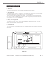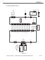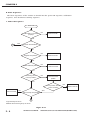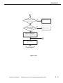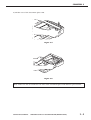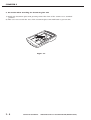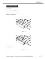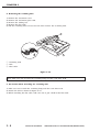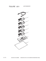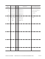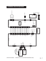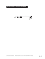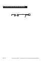
1
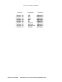
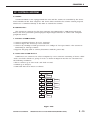
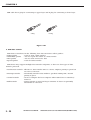
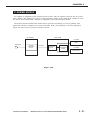
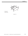
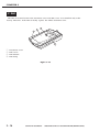
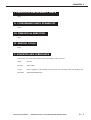
SERVICE
MANUAL
REVISION 0
JULY 2000
COPYRIGHT © 2000 CANON INC.
JY8-1318-00Z
CANOSCAN D660U REV.0 JULY 2000 PRINTED IN JAPAN (IMPRIME AU JAPON)
COPYRIGHT © 2000 CANON INC.
Printed in Japan
Imprimè au Japon
Use of this manual should be strictly supervised
to avoid disclosure of confidential information.
COPYRIGHT © 2000 CANON INC.
CANOSCAN D660U REV.0 JULY 2000 PRINTED IN JAPAN (IMPRIME AU JAPON)
LIST OF SERIAL NUMBER
Order No.
F91-4811-100
F91-4821-100
F91-4831-100
F91-4841-100
F91-4851-100
F91-4861-100
F91-4871-100
F91-4881-100
F91-4889-100
F91-4891-100
COPYRIGHT © 2000 CANON INC.
Destination
JPN
MLC
CCSI
EUR
UK
CA
CAN/CLA
SPL/CLA
ARGENTINA
HK/KOR
Serial No.
AZM000001MZM000001CZM000001DZM000001EZM000001FZM000001LZM000001JZM000001RZM000001KZM000001-
CANOSCAN D660U REV.0 JULY 2000 PRINTED IN JAPAN (IMPRIME AU JAPON)
PREFACE
This service manual contains the basic information necessary for servicing CanoScan D660U
image scanner.
The service manual consists of the following chapters.
CHAPTER 1 : GENERAL DESCRIPTIONS
Features, Specifications, Exterior Features, Installation, Customer’s Daily
Maintenance
CHAPTER 2 : GENERAL OPERATIONS
Basic Operation, Optical System, Image Processing System, Control System,
Power Supply
CHAPTER 3 : MECHANICAL SYSTEM
Externals, Drive System, Optical System, PCB, FAU
CHAPTER 4 : MAINTENANCE AND SERVICING
Periodical Replacement Parts, Consumable Parts Durability, Periodical
Servicing, Special Tools, Solvents and Lubricants
CHAPTER 5 : TROUBLESHOOTING
Initial Check, Troubleshooting, Location of Electrical Parts, Canon Scanner
Test
CHAPTER 6 : PARTS CATALOG
Accessory, Main Body
APPENDIX
: GENERAL CIRCUIT DIAGRAM, MAIN PCB CIRCUIT DIAGRAM, CCD DRIVE
PCB CIRCUIT DIAGRAM, BUTTON PCB CIRCUIT DIAGRAM, FAU BUTTON
PCB CIRCUIT DIAGRAM
The information in this service manual is subject to change as the product is improved. All
relevant information in such cases will be provided by the service information bulletins.
A thorough understanding of the CanoScan D660U, based on the service manual and service
information bulletins, is vital to the serviceman in maintaining the product quality and
performance, and in locating and repairing the cause of malfunctions.
COPYRIGHT © 2000 CANON INC.
CANOSCAN D660U REV.0 JULY 2000 PRINTED IN JAPAN (IMPRIME AU JAPON)
CONTENTS
CHAPTER 1 : GENERAL DESCRIPTIONS
C. Connecting to the Host
I.
FEATURES ..................................... 1-1
II.
SPECIFICATIONS ........................... 1-2
Computer ................................ 1-6
III. EXTERIOR FEATURES .................. 1-3
D. Connecting to FAU .................. 1-7
A. Front View ............................... 1-3
E. Connecting to Power Source . 1-7
B. Rear View ................................ 1-3
F.
IV. INSTALLATION .............................. 1-4
V.
Scanning a Document ............ 1-8
CUSTOMER’S DAILY
MAINTENANCE .............................. 1-9
A. Installation Conditions .......... 1-4
B. Unlocking the Scanning
Unit .......................................... 1-5
CHAPTER 2 : GENERAL OPERATIONS
I.
II.
BASIC OPERATION ........................ 2-1
D. Drive Motor Control
A. Functions ................................ 2-1
Circuit ................................... 2-15
B. Outline of Electrical System .. 2-2
III. IMAGE PROCESSING SYSTEM ... 2-16
C. Main PCB Input and Output ... 2-3
A. Outline .................................. 2-16
D. Basic Sequences ..................... 2-4
B. Image Processing
OPTICAL SYSTEM ....................... 2-10
Functions .............................. 2-16
A. Outline .................................. 2-10
IV. CONTROL SYSTEM ..................... 2-19
B. VAROS ................................... 2-11
A. Outline .................................. 2-19
C. Scanning Lamp/FAU Lamp
B. USB Interface ........................ 2-19
Lighting Circuit .................... 2-14
V.
POWER SUPPLY .......................... 2-21
CHAPTER 3 : MECHANICAL SYSTEM
I.
II.
EXTERNALS .................................. 3-1
A. Lamp Unit .............................. 3-10
A. Covers ...................................... 3-1
IV. PCB .............................................. 3-11
DRIVE SYSTEM .............................. 3-7
A. Main PCB ............................... 3-11
A. Motor Unit ............................... 3-7
B. Button PCB ........................... 3-12
III. OPTICAL SYSTEM ....................... 3-10
COPYRIGHT © 2000 CANON INC.
V.
FAU ............................................... 3-14
CANOSCAN D660U REV.0 JULY 2000 PRINTED IN JAPAN (IMPRIME AU JAPON)
CHAPTER 4 : MAINTENANCE AND SERVICING
I.
II.
PERIODICAL REPLACEMENT
III. PERIODICAL SERVICING .............. 4-1
PARTS ............................................ 4-1
IV. SPECIAL TOOLS ............................ 4-1
CONSUMABLE PARTS
V.
SOLVENTS AND LUBRICANTS ...... 4-1
DURABILITY .................................. 4-1
CHAPTER 5 : TROUBLESHOOTING
I.
II.
INITIAL CHECK .............................. 5-1
IV. CANON SCANNER TEST ................ 5-5
A. Operating Environment .......... 5-1
A. Outline .................................... 5-5
B. Others ...................................... 5-1
B. Operating Environment .......... 5-5
TROUBLESHOOTING ..................... 5-2
C. Functions ................................ 5-5
A. Faulty Image ............................ 5-2
D. Function Descriptions ............ 5-6
B. Faulty Operation ..................... 5-3
E. Error Message ....................... 5-12
III. LOCATION OF ELECTRICAL
PARTS ............................................ 5-4
CHAPTER 6 : PARTS CATALOG
FIGURE U01 ACCESSORY ............ 6-2
FIGURE U10 MAIN BODY .................... 6-4
APPENDIX
I.
GENERAL CIRCUIT DIAGRAM ..... A-1
II.
MAIN PCB CIRCUIT DIAGRAM ..... A-2
III. CCD DRIVE PCB CIRCUIT
DIAGRAM ...................................... A-4
COPYRIGHT © 2000 CANON INC.
IV. BUTTON PCB CIRCUIT
DIAGRAM ...................................... A-5
V.
FAU BUTTON PCB CIRCUIT
DIAGRAM ...................................... A-6
CANOSCAN D660U REV.0 JULY 2000 PRINTED IN JAPAN (IMPRIME AU JAPON)
CHAPTER 1
GENERAL DESCRIPTIONS
I.
FEATURES ..................................... 1-1
II.
SPECIFICATIONS ........................... 1-2
Computer ................................ 1-6
III. EXTERIOR FEATURES .................. 1-3
D. Connecting to FAU ................... 1-7
C. Connecting to the Host
A. Front View ............................... 1-3
E. Connecting to Power
B. Rear View ................................. 1-3
Source ..................................... 1-7
IV. INSTALLATION .............................. 1-4
A. Installation Conditions ........... 1-4
B. Unlocking the Scanning
F.
V.
Scanning a Document ............. 1-8
CUSTOMER’S DAILY
MAINTENANCE .............................. 1-9
Unit .......................................... 1-5
COPYRIGHT © 2000 CANON INC.
CANOSCAN D660U REV.0 JULY 2000 PRINTED IN JAPAN (IMPRIME AU JAPON)
CHAPTER 1
I. FEATURES
CanoScan D660U is a flatbed image scanner with 600 x 1200 dpi resolution incorporating the
following features.
1. Film Adapter Unit (FAU) is bult in the scanner for scanning negative and positive films.
2. Canon's proprietary VAROS (Variable Refraction Optical System) technology allows 1200
dpi resolution in the horizontal scanning direction when using FAU to scan films.
3. High-performance CCD and cold cathode fluorescent lamp used as light source achieve
high speed and high signal-to-noise ratio image quality. The lamp has high reliability.
4. The one-touch start button starts the accompanying software, and the FAU button allows
easy film scan.
5. Color gradation is naturally expressed by reading at 14 bits per RGB channel and
outputting at 8 bits.
6. The scanner is easily connected to the host computer through a USB interface.
COPYRIGHT © 2000 CANON INC.
CANOSCAN D660U REV.0 JULY 2000 PRINTED IN JAPAN (IMPRIME AU JAPON)
1-1
CHAPTER 1
II. SPECIFICATIONS
Main Unit
Type
: Flatbed image scanner
Reading Unit
Light source
Max. scan area
: Cold cathode fluorescent lamp
: 216 x 297 mm (Reflective document)
24 x 36 mm (Film)
Image output
: RGB 8 bits per channel (Input 14 bits)
Resolution
: 600 x 1200 dpi
(When scanning films) :1200 x 1200 dpi
Scan time
: 120 sec. (Color document/A4/600 dpi)
80 sec. (Grayscale document/A4/600 dpi)
120 sec. (Negative film/35mm/1200 dpi)
60 sec. (Positive film/35mm/1200 dpi)
Resolution conversion
: 1200/600/300/150/75 dpi (Horizontal)
1200/600/300/150 dpi (Vertical)
Interface
Interface
: USB
Others
Operating environment
Power consumption
Dimensions
Weight
: Temperature : 10 to 35 degrees
Relative humidity : 10 to 90%RH
Air pressure : 645 to 1013 hPa
: 15 W (During operation)
5 W (During standby)
1.5 W (During suspend)
: 260 (Width) x 440 (Depth) x 98 (Height) mm
: 2.6 kg
Specifications are subject to change without prior notice.
1-2
COPYRIGHT © 2000 CANON INC.
CANOSCAN D660U REV.0 JULY 2000 PRINTED IN JAPAN (IMPRIME AU JAPON)
CHAPTER 1
III. EXTERIOR FEATURES
A. Front View
1
3
4
q
w
e
r
Document Cover
Alignment Mark
Document Glass
Start Button
2
Figure 1-1
B. Rear View
1
4
q
w
e
r
3
2
Power Connector
FAU Port
USB Port
FAU Button
Figure 1-2
COPYRIGHT © 2000 CANON INC.
CANOSCAN D660U REV.0 JULY 2000 PRINTED IN JAPAN (IMPRIME AU JAPON)
1-3
CHAPTER 1
IV. INSTALLATION
A. Installation Conditions
The following installation conditions are required.
1. Ambient temperature should be between 10 and 35 degrees, and relative humidity between
10% and 90%RH. Avoid location near water faucets, boilers, humidifiers, or refrigerators.
2. Avoid location subject to open flame, dust, or direct sunlight. If it is installed near a
window, hang a curtain to block direct sunlight.
3. The room should be well ventilated.
4. Install on a sturdy and level desk, etc.
5. Moving a scanner from a cold place to a warm place may cause condensation on the metal
parts, resulting in a faulty operation. Give the scanner at least one hour to adjust to the
room temperature before unpacking.
1-4
COPYRIGHT © 2000 CANON INC.
CANOSCAN D660U REV.0 JULY 2000 PRINTED IN JAPAN (IMPRIME AU JAPON)
CHAPTER 1
B. Unlocking the Scanning Unit
The scanner is shipped with the scanning unit locked by the carriage lock to prevent a
damage during transport. Unlock the scanning unit before using the scanner.
1) Turn the scanner over.
Figure 1-3
2) Push the carriage lock to the "Unlock" position.
Figure 1-4
3) Return the scanner to its standard position.
Note: Ensure to lock the scanning unit during transport.
COPYRIGHT © 2000 CANON INC.
CANOSCAN D660U REV.0 JULY 2000 PRINTED IN JAPAN (IMPRIME AU JAPON)
1-5
CHAPTER 1
C. Connecting to the Host Computer
CanoScan D660U is connected to the USB port on the host computer using a USB cable
supplied with the scanner. Refer to the "Getting Started" for details. For connecting the host
computer's cables, refer to the manuals for the host computer.
1) Connect the square end of the USB cable to the USB port on the scanner.
2) Connect the rectangular end of the USB cable to the USB port on the host computer.
2
1
q USB Port
w USB Cable
Figure 1-5
1-6
COPYRIGHT © 2000 CANON INC.
CANOSCAN D660U REV.0 JULY 2000 PRINTED IN JAPAN (IMPRIME AU JAPON)
CHAPTER 1
D. Connecting to FAU
Connect the FAU cable (attached to the document cover) to the FAU port on the scanner.
2
1
q FAU Port
w FAU Cable
Figure 1-6
E. Connecting to Power Source
1) Connect the supplied AC adapter to the power connector on the scanner.
2) Plug the AC adapter into a power outlet.
1
2
q Power Connector
w AC Adapter
Figure 1-7
COPYRIGHT © 2000 CANON INC.
CANOSCAN D660U REV.0 JULY 2000 PRINTED IN JAPAN (IMPRIME AU JAPON)
1-7
CHAPTER 1
F. Scanning a Document
1) Open the document cover.
2) Place a document on the document glass, facing the image side down and aligning the
upper
corner with the alignment mark.
1
q Alignment Mark
Figure 1-8
3) Close the document cover, caring not to dislodge the document.
4) Send "SCAN" command from the host computer to scan.
1-8
COPYRIGHT © 2000 CANON INC.
CANOSCAN D660U REV.0 JULY 2000 PRINTED IN JAPAN (IMPRIME AU JAPON)
CHAPTER 1
V. CUSTOMER'S DAILY MAINTENANCE
Dirt on the document glass or document cover may cause an unclear image or lines on the
scanned image. Clean the document glass or document cover following the steps below.
1) Disconnect all cables from the scanner.
2) Wipe a dirt off with a soft clean cloth dampened with water and well wrung.
3) Thoroughly wipe water off with a dry cloth.
COPYRIGHT © 2000 CANON INC.
CANOSCAN D660U REV.0 JULY 2000 PRINTED IN JAPAN (IMPRIME AU JAPON)
1-9
CHAPTER 2
GENERAL OPERATIONS
I.
II.
D. Drive Motor Control
BASIC OPERATION ........................ 2-1
A. Functions ................................ 2-1
Circuit ................................... 2-15
B. Outline of Electrical System ... 2-2
III. IMAGE PROCESSING SYSTEM ... 2-16
C. Main PCB Input and Output ... 2-3
A. Outline .................................. 2-16
D. Basic Sequences .................... 2-4
B. Image Processing
OPTICAL SYSTEM ....................... 2-10
Functions .............................. 2-16
A. Outline .................................. 2-10
IV. CONTROL SYSTEM ..................... 2-19
B. VAROS ................................... 2-11
A. Outline .................................. 2-19
C. Scanning Lamp/FAU Lamp
B. USB Interface ........................ 2-19
Lighting Circuit ..................... 2-14
COPYRIGHT © 2000 CANON INC.
V.
POWER SUPPLY .......................... 2-21
CANOSCAN D660U REV.0 JULY 2000 PRINTED IN JAPAN (IMPRIME AU JAPON)
CHAPTER 2
I. BASIC OPERATION
A. Functions
The scanner functions are divided into the following three main systems.
1. Optical system
The optical system exposes a document by the scanning lamp and focuses the reflected light
from the document on the CCD by mirrors, a lens and a VAROS unit.
When scanning a film using FAU, turns OFF the scanning lamp to turn ON the FAU lamp,
and exposes the film by the FAU lamp and focuses the transparent light from the film on the
CCD by mirrors, a lens and a VAROS unit.
2. Image processing system
The image processing system converts the analog image signal focused on the CCD into
digital data and performs image processing.
3. Control system
The control system controls the interface with the host computer and the whole operation of
the scanner.
FAU inverter PCB
FAU
FAU lamp
BGR
Scanning
lamp
Drive motor
Host
computer
Scanning
unit
Optical system
B
G
R
CCD
VAROS Lens
unit
Control
system
Image processing system
Figure 2-1
COPYRIGHT © 2000 CANON INC.
CANOSCAN D660U REV.0 JULY 2000 PRINTED IN JAPAN (IMPRIME AU JAPON)
2-1
CHAPTER 2
B. Outline of Electrical System
CanoScan D660U is not equipped with CPU. The device driver installed in the host computer
includes a control program, which functions as CPU.
Analog Image signal read by the CCD are converted into digital data by ASIC. The converted
digital data are image-processed by the ASIC, and the ASIC temporarily stores the data in the
buffer RAM, and outputs to the host computer via USB port.
FAU lamp
FAU inverter PCB
FAU button
Main PCB
Host computer
Drive motor
USB
port
M1
Buffer
CCD drive PCB
Control
program
RAM
ASIC
Button PCB
Home
position
sensor
Start button
Inverter PCB
AC adapter
Scanning lamp
Figure 2-2
2-2
COPYRIGHT © 2000 CANON INC.
CANOSCAN D660U REV.0 JULY 2000 PRINTED IN JAPAN (IMPRIME AU JAPON)
COPYRIGHT © 2000 CANON INC.
2
3
4
CN2
AC adapter
J1
1
2
1
2
3
CN1
FAU button PCB
FAU inverter PCB
1
FAU lamp
USB
1
2
1
2
3
4
5
1
2
3
4
J4
J3
J1
+12V
GND
+12VI
GND
FAU Dect
FAU Button
DGND
DD+
GND
Main PCB
Flat Button
DGND
DGND
DGND
MB+
MBMA+
MA+12VM
+12VM
SENA
SENB
GND
GND
TR
VAROS
RS
CLP
PH1
PH2
DGND
+12V
VOR
AGND
VOG
AGND
VOB
AGND
HMSEN
VCC
GND
GND
+12VI
+12VI
J5
1
2
3
4
J2
1
2
3
4
5
6
7
8
9
10
11
12
13
14
15
16
17
18
19
20
21
22
23
24
25
26
27
28
29
30
CANOSCAN D660U REV.0 JULY 2000 PRINTED IN JAPAN (IMPRIME AU JAPON)
3
2
1
Button PCB
4
J1
J3
1
2
3
4
5
6
7
8
9
10
11
12
13
14
15
16
17
18
19
20
21
22
23
24
25
26
27
28
29
30
Home position
sensor
+12VI
GND
VCC
VAROS_ON
CCD
AA+
BB+
+12VM
+12VM
CCD drive PCB
1
2
1
2
3
4
5
6
J1
1
2
J2
J4
Drive
motor
Scanning lamp
CN1
1
2
3
Solenoid
Inverter
PCB
M1
CHAPTER 2
C. Main PCB Input and Output
Figure 2-3
2-3
CHAPTER 2
D. Basic Sequences
The basic sequences of the scanner is divided into the power ON sequence, calibration
sequence, and document scanning sequence.
1. Power ON sequence
Power ON
USB cable is connected
properly?
NO
Returns FALSE
YES
2
YES
Scanner was initialized?
NO
Register test passed?
NO
Returns FALSE
YES
NO
Buffer RAM test passed?
Returns FALSE
YES
NO
Scanning unit is
in home position?
Returns scanning
unit to the home
position
YES
Home position sensor
works normally?
Returns FALSE
NO
Returns FALSE
YES
NO
Light intensity test passed?
1
<Light intensity test error>
Initializes the scanner again up to 30 sec.
Figure 2-4-1
2-4
COPYRIGHT © 2000 CANON INC.
CANOSCAN D660U REV.0 JULY 2000 PRINTED IN JAPAN (IMPRIME AU JAPON)
CHAPTER 2
1
Home position sensor
works normally?
NO
Returns FALSE
YES
Scan start position
was detected?
NO
Returns FALSE
YES
Writes in register that
"scanner was initialized"
2
Returns TRUE
Standby
Figure 2-4-2
COPYRIGHT © 2000 CANON INC.
CANOSCAN D660U REV.0 JULY 2000 PRINTED IN JAPAN (IMPRIME AU JAPON)
2-5
CHAPTER 2
2. Calibration sequence
Standby
White shading
data is required?
NO
YES
Initializes buffer RAM control
Obtains 1 line of data
to buffer RAM
9 lines of data
was obtained?
Moves scanning unit
forward 9 lines
NO
YES
Returns scanning unit
to the home position
White shading data
is transmitted to host
computer?
NO
YES
Standby
Figure 2-5
2-6
COPYRIGHT © 2000 CANON INC.
CANOSCAN D660U REV.0 JULY 2000 PRINTED IN JAPAN (IMPRIME AU JAPON)
CHAPTER 2
1) Home position test
Checks if the scanning unit operates normally. When the scanner is powered ON, the
scanning unit automatically moves to the home position. This is also a scan start position.
1
2
q Home Position
w White Calibration Plate
Figure 2-6
2) Light intensity test
Checks if the light intensity of the scanning lamp reaches the standard value. When the
scanning lamp lights, the control program reads the light reflected from the white calibration
plate with the CCD, and checks if the light intensity into each CCD of red, green, and blue
reaches the standard value. If the light intensity is below the standard value, the control
program continues the test for up to 30 seconds. If it still does not reach the standard value,
the control program returns "FALSE".
COPYRIGHT © 2000 CANON INC.
CANOSCAN D660U REV.0 JULY 2000 PRINTED IN JAPAN (IMPRIME AU JAPON)
2-7
CHAPTER 2
3. Document scanning sequence
Standby
Document scan
is required?
NO
YES
Calculates the amount of
horizontal scan data and
the number of vertical scan
motor pulse
Sets scan parameter to ASIC,
and initializes buffer RAM
Moves scanning unit
to scan start position
Scanning unit moved?
NO
YES
Starts document scan
3
Figure 2-7-1
2-8
COPYRIGHT © 2000 CANON INC.
CANOSCAN D660U REV.0 JULY 2000 PRINTED IN JAPAN (IMPRIME AU JAPON)
CHAPTER 2
3
Scan cancellation
is required?
YES
NO
NO
Document was scanned?
YES
Returns scanning unit
Scanning unit returned
to the home position?
NO
YES
Stops drive motor
Image data was
transmitted?
NO
YES
Standby
Figure 2-7-2
COPYRIGHT © 2000 CANON INC.
CANOSCAN D660U REV.0 JULY 2000 PRINTED IN JAPAN (IMPRIME AU JAPON)
2-9
CHAPTER 2
II. OPTICAL SYSTEM
A. Outline
When scanning are flective document, the scanning lamp in the scanning unit exposes the
document and focuses the reflected light from the document on the CCD. When scanning a
film at 601 dpi or higher using FAU, FAU lamp built in the document cover exposes the film,
and optical axis is shifted by a half pixel in the horizontal scanning direction by means of
VAROS unit, and the images before and after the optical axis is shifted are composed by the
host computer.
2
1
Figure 2-8-1
3
4
q
w
e
r
t
VAROS Unit
CCD
Belt
Drive Motor
Scanning Lamp
5
Figure 2-8-2
2 - 10
COPYRIGHT © 2000 CANON INC.
CANOSCAN D660U REV.0 JULY 2000 PRINTED IN JAPAN (IMPRIME AU JAPON)
CHAPTER 2
B. VAROS
1. VAROS operation
VAROS is short for Variable Refraction Optical System. Refraction glass is placed between the
CCD and lens, and the direction of the refraction glass is moved to change the optical axis
thus changing the scanning position. When the host computer commands 601 dpi or higher
resolution to scan a film using FAU, two image data before and after the direction of the
refraction glass is moved are composed to make double image data. The resolution when using
VAROS is always 1200 dpi regardless of the command from the host computer.
The drive motor runs by the drive signal sent from the ASIC and drives the scanning unit via
the belt.
1
3
2
q Lens
w VAROS Unit
e Refraction Glass
Figure 2-9
COPYRIGHT © 2000 CANON INC.
CANOSCAN D660U REV.0 JULY 2000 PRINTED IN JAPAN (IMPRIME AU JAPON)
2 - 11
CHAPTER 2
2. Scanning by means of VAROS
There placed in order of the CCD, refraction glass, lens, and mirrors in the scanning unit.
The refraction glass is equipped with a solenoid to control the direction of the refraction glass.
When the host computer commands 601 dpi or higher resolution to scan a film using FAU, the
ASIC selects to use VAROS for scanning.
Firstly scans before moving the direction of the refraction glass at 600 dpi in the horizontal
scanning direction and 1200 dpi in the vertical scanning direction. The scanned image data is
stored in the host computer as a temporary data.
CCD
Vertical scan
Refraction glass
Film
Horizontal scan
Figure 2-10
2 - 12
COPYRIGHT © 2000 CANON INC.
CANOSCAN D660U REV.0 JULY 2000 PRINTED IN JAPAN (IMPRIME AU JAPON)
CHAPTER 2
After the 1st scan, the ASIC turns signal ON to drive the solenoid to change the direction of
the refraction glass. Changing the direction of the refraction glass shifts the optical axis from
the CCD to a film by a half pixel. Therefore, the 2nd scan is performed between the pixels of
the 1st scan.
CCD
Refraction glass
Vertical scan
Horizontal scan
Film
Figure 2-11
These image data are composed in the host computer to output 1200 x 1200 dpi image data.
When the ASIC commands between 601 dpi and 1199 dpi, scan is performed at 1200 dpi, then
the host computer performs resolution conversion to output the image data conforming to the
command by the ASIC.
COPYRIGHT © 2000 CANON INC.
CANOSCAN D660U REV.0 JULY 2000 PRINTED IN JAPAN (IMPRIME AU JAPON)
2 - 13
CHAPTER 2
C. Scanning lamp/FAU lamp lighting circuit
When the scanner is powered ON, the "LAMP ON" signal is set to "H" and turns ON the lamp
control circuit to provide +12VI to the inverter PCB to light the scanning lamp.
The scanning lamp exposure control is performed by scanning white calibration plate which
is placed outside the image area to feedback on the output. ASIC inputs the pulse signal
(LAMP ON) according to the feedbacked signal to the lamp control circuit to generate +12VI.
FAU lamp exposure control is performed by directly feedbacking the output from the FAU
lamp. When the host computer commands to use the FAU, ASIC sets "FAU INV" signal to "H".
The lamp control circuit provides +12VI to FAU inverter PCB to light the FAU lamp.
CCD
drive
PCB
LAMPON
Host
computer
ASIC
Lamp
control
circuit
Inverter
PCB
Scanning
lamp
Cold cathode
fluorescent
lamp
GND
12VI
FAUINV
GND
FAU lamp
FAU Inverter
PCB
Main PCB
Cold cathode
fluorescent
lamp
Figure 2-12
2 - 14
COPYRIGHT © 2000 CANON INC.
CANOSCAN D660U REV.0 JULY 2000 PRINTED IN JAPAN (IMPRIME AU JAPON)
CHAPTER 2
D. Drive Motor Control Circuit
When the host computer sends a command to change scaling/resolution, the ASIC generates
the control signal (A+, A-, B+, B-) and sends the signal to the drive motor via the motor driver.
When the host computer changes its command to the ASIC, the ASIC changes its control
signal to control the motor driver.
CCD drive PCB
Main PCB
Drive motor
M1
Host computer
Motor
driver
A+
AB+
B-
ASIC
Figure 2-13
COPYRIGHT © 2000 CANON INC.
CANOSCAN D660U REV.0 JULY 2000 PRINTED IN JAPAN (IMPRIME AU JAPON)
2 - 15
CHAPTER 2
III. IMAGE PROCESSING SYSTEM
A. Outline
The image processing system converts analog image signals read by the CCD into digital
data, performs various image processing, then outputs the data to the host computer via USB
port. Shading correction and gamma correction are performed by the driver software instead of
the scanner function.
1. CCD
2. A/D
conversion
3. Shading
correction
4. Gamma
correction
5. Resolution
conversion
To host computer
Figure 2-14
B. Image Processing Functions
1. CCD
The ASIC outputs clock signals based on the command from the host computer to the CCD.
The scanner uses a 3 line CCD to read the color signals. The 3 line CCD is a single chip
photoelectric conversion device which consists of 3 lines of several thousand photosensitive
devices, each several microns square, reading for red, green, and blue analog image signals,
and of a scanning circuit.
Blue photosensitive section
Green photosensitive section
Red photosensitive section
Figure 2-15
2. A/D conversion
Analog image signals output from the CCD are converted into the digital data of 14 bits each
by A/D converter in the ASIC in order of red, green, and blue image signals.
2 - 16
COPYRIGHT © 2000 CANON INC.
CANOSCAN D660U REV.0 JULY 2000 PRINTED IN JAPAN (IMPRIME AU JAPON)
CHAPTER 2
3. Shading correction
When the CCD reads a document of even density, the image signal corresponding to each
pixel is not uniform for the following reasons.
1) Light intensity of the scanning lamp is not uniform.
2) There is variation in the sensitivity of the light phototransistors.
3) There is a slight output from the light phototransistors even when there is no input.
These variations are corrected by the shading correction. Calibration data is used as
standard density data when scanning a document. Scanned image data is compared to the
standard density data for the image data correction.
4. Gamma correction
Shading-corrected red, green and blue image data are divided uniformly into 16384
gradations according to the document density. The contrast and density of this image data are
adjusted by the gamma correction. The ASIC writes gamma curve specified by the host
computer into the buffer RAM before scanning a document. Image scan starts and the image
data input to the buffer RAM is converted by the gamma curve data and is output.
5. Resolution conversion
1) Resolution conversion in the horizontal scanning direction
Basic resolution is 600 dpi, and selective at 600 dpi, 300 dpi, 150 dpi, and 75 dpi.
Resolution conversion in the horizontal scanning direction is performed by averaging the
image data of the basic resolution as shown in Figure 2-16.
A
B
A'
A'=(A+B)/2
C
C'
D
E
F
G
E'
C'=(C+D)/2
H
G'
E'=(E+F)/2
Figure 2-16
COPYRIGHT © 2000 CANON INC.
CANOSCAN D660U REV.0 JULY 2000 PRINTED IN JAPAN (IMPRIME AU JAPON)
2 - 17
CHAPTER 2
2) Resolution conversion in the vertical scanning direction
The ASIC changes the scanning unit moving speed to change the resolution in the vertical
scanning direction. When increasing the resolution, the scanning unit moves at a low speed to
read more lines as shown in Figure 2-18.
Sampling point
Moving direction
Scanning unit
Figure 2-17
Sampling point
Moving direction
Scanning unit
Figure 2-18
When decreasing the resolution, the scanning unit moves at a faster speed to read less lines.
Sampling point
Moving direction
Scanning unit
Figure 2-19
2 - 18
COPYRIGHT © 2000 CANON INC.
CANOSCAN D660U REV.0 JULY 2000 PRINTED IN JAPAN (IMPRIME AU JAPON)
CHAPTER 2
IV. CONTROL SYSTEM
A. Outline
CanoScan D660U is not equipped with the CPU and the scanner is controlled by the device
driver installed in the host computer. The device driver includes the scanner control program,
which sets a command directly to the ASIC to control the scanner.
B. USB Interface
The scanner is connected to the host computer via USB interface. USB (Universal Serial
Bus) is the next generation general-purpose input-output interface to connect the computer
peripheral devices.
1. Features of USB includes;
* Connects peripheral devices by a tree structure.
* Connects up to 127 devices by a tree structure.
* Connects by 12 Mbps of "full speed mode" or 1.5 Mbps of "low speed mode". The scanner is
conforming to "full speed mode".
* Supports hot plug (able to connect/disconnect with the power ON)
2. Connection to USB devices
USB devices are connected to a host computer by a tree structure consisting of device called
"node" and "hub" which is a group of "node" as shown in Figure 2-20. The tree structure has
the following conditions.
* Able to connect up to 127 "node" and "hub" in total.
* Limited up to 6 layers.
* USB cable must be 5 meters or shorter.
Host computer
Hub 1
Node
Hub 2
Node
Hub 3
Hub 6
Node
Hub 4
Node
Node
Hub 5
Node
Node
Node
Node
Figure 2-20
COPYRIGHT © 2000 CANON INC.
CANOSCAN D660U REV.0 JULY 2000 PRINTED IN JAPAN (IMPRIME AU JAPON)
2 - 19
CHAPTER 2
USB cable has A plug for connecting to upper layer and B plug for connecting to lower layer.
A Plug
B Plug
Figure 2-21
3. USB data transfer
*
*
*
*
USB data is transferred in the following four data structures called "packet".
Token packet
: Used to start a data transfer
Handshake packet
: Used to report the status of a data transfer
Data packet
: Used to send and receive data
Special packet
: Used for other transfer
USB device may support multiple data transfer endpoints, so there are four types of data
transfer protocols.
* Isochronous transfer : Allocates a data transfer time to a device. Highest priority is given but
no error is corrected.
* Interrupt transfer
: Periodically transfers data within a specified waiting time. Second
priority is given.
* Control transfer
: Used to configure the host computer when USB device is attached/
removed.
* Bulk transfer
: Lowest priority is given but larger amounts of data is sequentially
transferred to a free bus.
2 - 20
COPYRIGHT © 2000 CANON INC.
CANOSCAN D660U REV.0 JULY 2000 PRINTED IN JAPAN (IMPRIME AU JAPON)
CHAPTER 2
V. POWER SUPPLY
AC adapter is supplied for the scanner power source. The AC adapter converts the AC power
into +12VDC. The output DC power is converted into +5VDC in the main PCB. +5VDC is used
for the IC in the main PCB. +12VDC is supplied to the CCD and drive motor.
Protection circuit is built-in the main PCB to prevent overvoltage or reverse polarity. The
protection circuit is composed of a fuse and zener diode. If overvoltage or reverse polarity is
input, the fuse burns to protect a further circuit.
AC adapter
Main PCB
+12 VDC
CCD
AC power
AC/DC
conversion
circuit
+12 VDC
Protection
circuit
+5 VDC
conversion
circuit
+12 VDC
Drive motor
Figure 2-22
COPYRIGHT © 2000 CANON INC.
CANOSCAN D660U REV.0 JULY 2000 PRINTED IN JAPAN (IMPRIME AU JAPON)
2 - 21
CHAPTER 3
MECHANICAL SYSTEM
I.
II.
EXTERNALS .................................. 3-1
A. Lamp Unit .............................. 3-10
A. Covers ...................................... 3-1
IV. PCB .............................................. 3-11
DRIVE SYSTEM .............................. 3-7
A. Main PCB ............................... 3-11
A. Motor Unit ............................... 3-7
B. Button PCB ........................... 3-12
III. OPTICAL SYSTEM ....................... 3-10
COPYRIGHT © 2000 CANON INC.
V.
FAU ............................................... 3-14
CANOSCAN D660U REV.0 JULY 2000 PRINTED IN JAPAN (IMPRIME AU JAPON)
CHAPTER 3
I. EXTERNALS
When cleaning, checking or repairing inside the scanner, remove the necessary covers using
the following procedures.
A. Covers
1
2
3
q Document Cover
w Document Glass Unit
e Base Frame
Figure 3-1
COPYRIGHT © 2000 CANON INC.
CANOSCAN D660U REV.0 JULY 2000 PRINTED IN JAPAN (IMPRIME AU JAPON)
3-1
CHAPTER 3
1. Removing the document cover
1) Disconnect the FAU cable.
2) Pull up the hinges to remove the document cover.
1
2
2
3
q Document Cover
w Hinge
e FAU Cable
Figure 3-2
3-2
COPYRIGHT © 2000 CANON INC.
CANOSCAN D660U REV.0 JULY 2000 PRINTED IN JAPAN (IMPRIME AU JAPON)
CHAPTER 3
2. Removing the document glass unit
1) Remove the document cover.
2) Unhook the hook on the front of the document glass unit, then lift the hook part.
3
2
1
q Hook
w Hook Part
e Document Glass Unit
Figure 3-3
Note: Take care not to lift the hook part excessively since it is attached to the document
glass with a double-sided tape.
COPYRIGHT © 2000 CANON INC.
CANOSCAN D660U REV.0 JULY 2000 PRINTED IN JAPAN (IMPRIME AU JAPON)
3-3
CHAPTER 3
3) Unhook the hook on the rear of the document glass unit, then slide the document glass
unit forward.
1
2
1
q Hook
w Document Glass Unit
Figure 3-4
3-4
COPYRIGHT © 2000 CANON INC.
CANOSCAN D660U REV.0 JULY 2000 PRINTED IN JAPAN (IMPRIME AU JAPON)
CHAPTER 3
4) Lift the rear of the document glass unit.
Figure 3-5
Figure 3-6
Note: Take care not to touch the rear side of the document glass with hand to prevent dirt.
COPYRIGHT © 2000 CANON INC.
CANOSCAN D660U REV.0 JULY 2000 PRINTED IN JAPAN (IMPRIME AU JAPON)
3-5
CHAPTER 3
3. Precaution when attaching the document glass unit
1) Attach the document glass unit pressing toward the front of the scanner as a standard
position.
2) Take care not to touch the rear of the document glass unit with hand to prevent dirt.
Figure 3-7
3-6
COPYRIGHT © 2000 CANON INC.
CANOSCAN D660U REV.0 JULY 2000 PRINTED IN JAPAN (IMPRIME AU JAPON)
CHAPTER 3
II. DRIVE SYSTEM
A. Motor Unit
1. Removing the sliding rod
1)
2)
3)
4)
Remove
Remove
Remove
Remove
the document cover.
the document glass unit.
one screw to remove the sliding rod cover.
the sliding rod.
2
1
Figure 3-8
3
q Screw
w Sliding Rod Cover
e Sliding Rod
Figure 3-9
COPYRIGHT © 2000 CANON INC.
CANOSCAN D660U REV.0 JULY 2000 PRINTED IN JAPAN (IMPRIME AU JAPON)
3-7
CHAPTER 3
2. Removing the scanning unit
1)
2)
3)
4)
5)
Remove the document cover.
Remove the document glass unit.
Remove the sliding rod.
Remove the flat cable.
Lift the scanning unit to loose the belt, then remove the scanning unit.
1
2
3
q Scanning Unit
w Belt
e Flat Cable
Figure 3-10
Note: Take care not to touch the scanning lamp and the CCD drive PCB.
3. Precaution when attaching the scanning unit
1) Take care not to touch the scanning lamp and the CCD drive PCB.
2) Attach the belt as shown in Figure 3-10.
3) When attaching the flat cable, take care not to put a hold in the flat cable.
3-8
COPYRIGHT © 2000 CANON INC.
CANOSCAN D660U REV.0 JULY 2000 PRINTED IN JAPAN (IMPRIME AU JAPON)
CHAPTER 3
4. Removing the drive motor
1)
2)
3)
4)
5)
6)
Remove
Remove
Remove
Remove
Remove
Remove
the document cover.
the document glass unit.
the sliding rod.
the scanning unit.
two screws and lamp cable to remove the lamp unit.
two screws and drive motor cable, then remove the drive motor.
3
7
3
2
6
1
q
w
e
r
t
y
u
Scanning Unit
Lamp Unit
Screw
Drive Motor Cable
Drive Motor
Lamp Cable
Screw
5
4
Figure 3-11
Note: Do not remove the CCD drive PCB from the scanning unit since it must be adjusted
at the factory.
COPYRIGHT © 2000 CANON INC.
CANOSCAN D660U REV.0 JULY 2000 PRINTED IN JAPAN (IMPRIME AU JAPON)
3-9
CHAPTER 3
III. OPTICAL SYSTEM
A. Lamp Unit
1. Removing the lamp unit
1)
2)
3)
4)
5)
Remove
Remove
Remove
Remove
Remove
the document cover.
the document glass unit.
the sliding rod.
the scanning unit.
two screws and lamp cable to remove the lamp unit.
1
1
2
q Screw
w Lamp Cable
Figure 3-12
1
q Lamp Unit
Figure 3-13
3 - 10
COPYRIGHT © 2000 CANON INC.
CANOSCAN D660U REV.0 JULY 2000 PRINTED IN JAPAN (IMPRIME AU JAPON)
CHAPTER 3
IV. PCB
A. Main PCB
1. Removing the main PCB
1) Remove the document cover.
2) Remove the document glass unit.
3) Remove the flat cable, button cable, and two screws, then remove the main PCB.
4
5
2
1
3 1
90
5
4
2
1
3
q
w
e
r
t
Button Cable
Screw
Main PCB
Flat Cable
Ferrite Core Holder
Figure 3-14
2. Precaution when attaching the main PCB
1) Remove two screws to remove the ferrite core holder temporarily.
2) Connect the flat cable to the main PCB.
3) Bend the button cable at 90 degrees when connecting to the main PCB as shown in Figure
3-14.
COPYRIGHT © 2000 CANON INC.
CANOSCAN D660U REV.0 JULY 2000 PRINTED IN JAPAN (IMPRIME AU JAPON)
3 - 11
CHAPTER 3
B. Button PCB
1. Removing the button PCB
1)
2)
3)
4)
5)
6)
Remove the document cover.
Remove the document glass unit.
Move the scanning unit to the center.
Remove the button cable.
Remove two screws.
Remove the start button from the button PCB, caring not to lose the button spring.
1
Figure 3-15
4
3
q
w
e
r
2
Start Button
Button Cable
Screw
Button PCB
Figure 3-16
3 - 12
COPYRIGHT © 2000 CANON INC.
CANOSCAN D660U REV.0 JULY 2000 PRINTED IN JAPAN (IMPRIME AU JAPON)
CHAPTER 3
3
2
3
1
q Button PCB
w Start Button
e Button Spring
Figure 3-17
COPYRIGHT © 2000 CANON INC.
CANOSCAN D660U REV.0 JULY 2000 PRINTED IN JAPAN (IMPRIME AU JAPON)
3 - 13
CHAPTER 3
V. FAU
The FAU is located between the document cover and FAU cover. It is installed only at the
factory. Therefore, if the FAU is faulty, replace the whole document cover.
3
2
1
4
q
w
e
r
Document Cover
FAU Cover
FAU Button
FAU lamp
Figure 3-18
3 - 14
COPYRIGHT © 2000 CANON INC.
CANOSCAN D660U REV.0 JULY 2000 PRINTED IN JAPAN (IMPRIME AU JAPON)
CHAPTER 4
MAINTENANCE AND SERVICING
I.
II.
PERIODICAL REPLACEMENT
III.
PERIODICAL SERVICING ............ 4-1
PARTS ......................................... 4-1
IV.
SPECIAL TOOLS ......................... 4-1
CONSUMABLE PARTS
V.
SOLVENTS AND LUBRICANTS .... 4-1
DURABILITY ................................ 4-1
COPYRIGHT © 2000 CANON INC.
CANOSCAN D660U REV.0 JULY 2000 PRINTED IN JAPAN (IMPRIME AU JAPON)
CHAPTER 4
I. PERIODICAL REPLACEMENT PARTS
None
II. CONSUMABLE PARTS DURABILITY
None
III. PERIODICAL SERVICING
None
IV. SPECIAL TOOLS
None
V. SOLVENTS AND LUBRICANTS
Lubricants used for disassembly and reassembly of the scanner.
Name
: Grease
Tool No.
: TKC-0955
Usage
: To be applied to the sliding part between the scanning unit and sliding rod.
Remarks
: MOLYKOTE EM-50L
COPYRIGHT © 2000 CANON INC.
CANOSCAN D660U REV.0 JULY 2000 PRINTED IN JAPAN (IMPRIME AU JAPON)
4-1
CHAPTER 5
TROUBLESHOOTING
I.
II.
INITIAL CHECK .............................. 5-1
IV. CANON SCANNER TEST ................ 5-5
A. Operating Environment .......... 5-1
A. Outline .................................... 5-5
B. Others ...................................... 5-1
B. Operating Environment .......... 5-5
TROUBLESHOOTING ..................... 5-2
C. Functions ................................ 5-5
A. Faulty Image ............................ 5-2
D. Function Descriptions ............ 5-6
B. Faulty Operation ..................... 5-3
E. Error Message ....................... 5-12
III. LOCATION OF ELECTRICAL
PARTS ............................................ 5-4
COPYRIGHT © 2000 CANON INC.
CANOSCAN D660U REV.0 JULY 2000 PRINTED IN JAPAN (IMPRIME AU JAPON)
CHAPTER 5
I. INITIAL CHECK
A. Operating Environment
Check if the operating environment conforms to the following conditions.
1. Line voltage is within ±10% of the rated value.
2. Ambient temperature and humidity conform to the operating environment. (Refer to
CHAPTER 1, II. SPECIFICATIONS)
3. The scanner is not installed near a water faucet, boiler, humidifier, open flame, or in dusty
place.
4. The scanner is not exposed to direct sunlight. If it must be installed by a window, hang a
curtain to block direct sunlight.
5. The scanner is installed in a well-ventilated place.
B. Others
Moving a scanner from a cold place to a warm place can cause condensation on the metal
parts, resulting in a faulty operation.
COPYRIGHT © 2000 CANON INC.
CANOSCAN D660U REV.0 JULY 2000 PRINTED IN JAPAN (IMPRIME AU JAPON)
5-1
CHAPTER 5
II. TROUBLESHOOTING
Causes and corrective actions against possible faulty image and faulty operation are listed
below.
A. Faulty Image
1. Image not output
Cause 1
: Faulty connection of the USB cable
Corrective action : Securely connect the USB cable.
Cause 2
: Faulty scanning lamp when scanning in flatbed mode
Corrective action : Replace the lamp unit.
Cause 3
: Faulty FAU when scanning a film
Corrective action : Replace the document cover.
Cause 4
: Faulty CCD
Corrective action : Replace the scanning unit.
Cause 5
: Faulty main PCB
Corrective action : Replace the main PCB.
2. Uneven image density or lines
Cause 1
: Dirt on the document cover or document glass
Corrective action : Clean the document cover or document glass.
Cause 2
: Faulty calibration data
Corrective action : Scan again.
Cause 3
: External light is entering into the scanner. External light entering into
the CCD can cause uneven image density.
Corrective action : Fully close the document cover. If it is impossible, cover with a sheet etc.
to prevent external light.
Cause 4
: Faulty CCD
Corrective action : Replace the scanning unit.
Cause 5
: Faulty main PCB
Corrective action : Replace the main PCB.
5-2
COPYRIGHT © 2000 CANON INC.
CANOSCAN D660U REV.0 JULY 2000 PRINTED IN JAPAN (IMPRIME AU JAPON)
CHAPTER 5
B. Faulty Operation
1. Host computer not detecting the scanner
Cause 1
: Faulty installation of the device driver
Corrective action : Uninstall the device driver and reinstall it.
Cause 2
: Faulty connection of the USB cable
Corrective action : Securely connect the USB cable to the scanner and host computer.
Cause 3
: Faulty main PCB
Corrective action : Replace the main PCB.
2. Scanner not operating
Cause 1
: Carriage lock is locked.
Corrective action : Unlock the carriage lock.
Cause 2
: Faulty connection of the flat cable
Corrective action : Securely connect the flat cable to the scanning unit and main PCB.
Cause 3
: Faulty scanning lamp
Corrective action : Replace the lamp unit.
Cause 4
: Faulty FAU
Corrective action : Replace the document cover.
Cause 5
: Faulty CCD
Corrective action : Replace the scanning unit.
Cause 6
: Faulty main PCB
Corrective action : Replace the main PCB.
3. Drive motor not running
Cause 1
: Faulty connection of the flat cable
Corrective action : Securely connect the flat cable.
Cause 2
: Faulty drive motor
Corrective action : Replace the drive motor.
Cause 3
: Faulty motor driver
Corrective action : Replace the scanning unit.
Cause 4
: Faulty main PCB
Corrective action : Replace the main PCB.
COPYRIGHT © 2000 CANON INC.
CANOSCAN D660U REV.0 JULY 2000 PRINTED IN JAPAN (IMPRIME AU JAPON)
5-3
CHAPTER 5
III. LOCATION OF ELECTRICAL PARTS
7
8
3
2
6
1
4
5
q
w
e
r
t
y
u
i
Main PCB
Home Position Sensor
CCD Drive PCB
Drive Motor
Start Button
Inverter PCB
FAU Button
FAU Inverter PCB
Figure 5-1
5-4
COPYRIGHT © 2000 CANON INC.
CANOSCAN D660U REV.0 JULY 2000 PRINTED IN JAPAN (IMPRIME AU JAPON)
CHAPTER 5
IV. CANON SCANNER TEST
A. Outline
Canon Scanner Test is utility software to check if faulty scanner operation is due to
hardware or communication with a host computer.
* For Windows
ScanTest.exe (Japanese/English is switched according to the language used in Windows.)
* For Macintosh
ScantestD660Uj (Japanese)/ScantestD660Ue (English)
B. Operating Environment
Windows platform
1) CanoScan D660U
2) PC/AT Compatibles (Pentium or faster is recommended.)
3) Windows 98 or Windows 2000 Operating System
4) Scanner Device Driver
Macintosh platform
1) CanoScan D660U
2) Power Macintosh
3) Macintosh OS (Version 8.5 or later)
4) Scanner Device Driver
Note: Install the scanner device driver before using the Canon Scanner Test.
C. Functions
1. USB information (Windows only)
Scanner information recognized by Windows.
2. Scanner information
Product ID, ROM version, etc. are shown when the scanner is properly communicated with
the host computer.
3. Scanner self test
Scanner self test is performed.
4. Scan
Any image is scanned and saved as an image file in the same folder with the Canon Scanner
Test.
COPYRIGHT © 2000 CANON INC.
CANOSCAN D660U REV.0 JULY 2000 PRINTED IN JAPAN (IMPRIME AU JAPON)
5-5
CHAPTER 5
D. Function Descriptions
1. USB information (Windows only)
Select "USB Information" from the "Function" menu to display as shown in Figure 5-2
(Windows).
Figure 5-2
·
·
·
·
Vendor Description
Device Description
Port Name
Local Name
5-6
:
:
:
:
Manufacturer name (Canon) of the scanner connected.
Product name of the scanner connected.
Port name of the scanner recognized by Windows.
Product name of the scanner connected.
COPYRIGHT © 2000 CANON INC.
CANOSCAN D660U REV.0 JULY 2000 PRINTED IN JAPAN (IMPRIME AU JAPON)
CHAPTER 5
2. Scanner information
Select "Scanner Information" from the "Function" menu to display as shown in Figure 5-3
(Windows) or Figure 5-4 (Macintosh).
Figure 5-3
Figure 5-4
· Vendor ID
· Product ID
· ROM Version
: Manufacturer name (Canon) of the scanner connected.
: Product name of the scanner connected.
: ASIC version.
COPYRIGHT © 2000 CANON INC.
CANOSCAN D660U REV.0 JULY 2000 PRINTED IN JAPAN (IMPRIME AU JAPON)
5-7
CHAPTER 5
3. Scanner self test
Select "Scanner self test" from the "Function" menu to display a dialog as shown in Figure
5-5 (Windows) or Figure 5-6 (Macintosh).
Figure 5-5
Figure 5-6
5-8
COPYRIGHT © 2000 CANON INC.
CANOSCAN D660U REV.0 JULY 2000 PRINTED IN JAPAN (IMPRIME AU JAPON)
CHAPTER 5
Click "OK" to perform Scanner self test. When it has completed normally, a dialog as shown
in Figure 5-7 (Window) or Figure 5-8 (Macintosh) is displayed.
Figure 5-7
Figure 5-8
COPYRIGHT © 2000 CANON INC.
CANOSCAN D660U REV.0 JULY 2000 PRINTED IN JAPAN (IMPRIME AU JAPON)
5-9
CHAPTER 5
4. Scan
Select "Scan" from the "Function" menu to display a dialog as shown in Figure 5-9
(Windows) or Figure 5-10 (Macintosh).
Figure 5-9
5 - 10
COPYRIGHT © 2000 CANON INC.
CANOSCAN D660U REV.0 JULY 2000 PRINTED IN JAPAN (IMPRIME AU JAPON)
CHAPTER 5
Figure 5-10
* Scan count
* Resolution
* Image
: Specify the number of scan.
: Select a resolution for the image to be scanned.
: Select a handling method of the scanned image. When "Read in memory (no
file)" is selected, scanned image is read into the memory, then abandoned
after readout. When "Save to TIFF file" is selected, the file of "img0.tif" is set
up in the same folder with the Canon Scanner Test.
File volume is as follows.
75 dpi : Approx. 1.6 MByte
150 dpi : Approx. 6.5 MByte
300 dpi : Approx. 26.2 MByte
600 dpi : Approx. 104.9 MByte
Note: Confirm before scanning that the available disk space on the HDD in which the
Canon Scanner Test is installed exceeds above file volume.
COPYRIGHT © 2000 CANON INC.
CANOSCAN D660U REV.0 JULY 2000 PRINTED IN JAPAN (IMPRIME AU JAPON)
5 - 11
CHAPTER 5
E. Error Message
Causes and corrective actions for error messages which may occur during Canon Scanner
Test are described below.
1. When Canon scanner test is started, "Unable to find USB scanner" is displayed.
Cause 1
: Device driver for the scanner is not installed in the host computer.
Corrective action : Install the device driver.
Cause 2
: Scanner is not detected by the host computer.
Corrective action : Properly detect the scanner by the host computer.
2. Scanner information is not displayed or scanner self test terminates without scan
operation.
Cause 1
: Carriage lock is locked.
Corrective action : Unlock the carriage lock.
Cause 2
: Scanner is not detected by the host computer.
Corrective action : Properly detect the scanner by the host computer.
Cause 3
: Faulty flat cable
Corrective Action : Check the flat cable connector. If it is normal, replace the flat cable.
Cause 4
: Faulty CCD
Corrective Action : Replace the scanning unit.
Cause 5
: Faulty main PCB
Corrective Action : Replace the main PCB.
3. "Carriage lock is locked" is displayed.
Cause 1
: Carriage lock is locked.
Corrective Action : Unlock the carriage lock.
Cause 2
: Faulty drive motor
Corrective Action : Replace the drive motor.
Cause 3
: Faulty home position sensor
Corrective Action : Replace the scanning unit.
4. "Unable to open file" is displayed.
Cause
: Canon scanner test is started from a CD-ROM or write-protect HDD.
Corrective Action : Copy the Canon scanner test on a writable HDD to use.
5 - 12
COPYRIGHT © 2000 CANON INC.
CANOSCAN D660U REV.0 JULY 2000 PRINTED IN JAPAN (IMPRIME AU JAPON)
CHAPTER 6
PARTS CATALOG
FIGURE U01 ACCESSORY ............. 6 - 2
COPYRIGHT © 2000 CANON INC.
FIGURE U10 MAIN BODY .................... 6 - 4
CANOSCAN D660U REV.0 JULY 2000 PRINTED IN JAPAN (IMPRIME AU JAPON)
(Blank Page)
COPYRIGHT © 2000 CANON INC.
CANOSCAN D660U REV.0 JULY 2000 PRINTED IN JAPAN (IMPRIME AU JAPON)
6-1
FIGURE U01
ACCESSORY
1
2
3
4
5
6
7
8
6-2
COPYRIGHT © 2000 CANON INC.
CANOSCAN D660U REV.0 JULY 2000 PRINTED IN JAPAN (IMPRIME AU JAPON)
R
A
N
K
Q'
T
Y
FIGURE
&
KEY NO.
PART NUMBER
U01-01
104-0138-0SP
1
CABLE, USB
02
003-0269-0SP
1
ADAPTER, AC
JPN/CCSI/CANADA/CLA
03
003-2164-0SP
1
ADAPTER, AC
CSPL/CLA/EUR
003-2191-0SP
1
ADAPTER, AC
HK/LOTTE
04
003-2163-0SP
1
ADAPTER, AC
UK
05
003-2162-0SP
1
ADAPTER, AC
ARGENTINA/CA
06
003-2190-0SP
1
ADAPTER, AC
CHINA
07
NPN
1
FILM GUIDE
08
NPN
1
COVER, FAU
COPYRIGHT © 2000 CANON INC.
DESCRIPTION
SERIAL NUMBER/REMARKS
CANOSCAN D660U REV.0 JULY 2000 PRINTED IN JAPAN (IMPRIME AU JAPON)
6-3
FIGURE U10
MAIN BODY
7
8
1
23
21
2
22
10
20
19
11
24
3 4
21
12
14
5
13
9
15 16
6
17
18
6-4
COPYRIGHT © 2000 CANON INC.
CANOSCAN D660U REV.0 JULY 2000 PRINTED IN JAPAN (IMPRIME AU JAPON)
R
A
N
K
Q'
T
Y
FIGURE
&
KEY NO.
PART NUMBER
U10-01
003-5244-0SP
1
DOCUMENT COVER ASSEMBLY
02
002-0841-0SP
1
PLATEN GLASS ASSEMBLY
03
051-0544-0SP
1
BUTTON
04
004-0399-0SP
1
BUTTON PCB ASSEMBLY
05
104-0153-0SP
1
CABLE, BUTTON
06
NPN
1
BASE FRAME
07
051-0541-0SP
1
HINGE(R)
08
051-0540-0SP
1
HINGE(L)
09
077-0626-0SP
1
SCREW, M3X6, TAPPING
10
065-0054-0SP
1
MOTOR ASSEMBLY
11
002-0963-0SP
1
LAMP ASSEMBLY
12
104-0162-0SP
1
FLEXIBLE FLAT CABLE
13
003-5256-0SP
1
OPTICAL ASSEMBLY
14
003-5255-0SP
1
MAIN PCB ASSEMBLY
15
051-0568-0SP
1
COVER, SLIDING ROD
16
NPN
1
SLIDING ROD
17
003-2157-0SP
1
BELT ASSEMBLY
18
051-0546-0SP
1
LOCK, CARRIAGE
19
NPN
1
CORE, FERRITE
20
NPN
1
HOLDER, FERRITE CORE
21
077-0601-0SP
4
SCREW, M3X6, TAPPING
22
077-0627-0SP
2
SCREW, M3X6, WITH SW
23
077-0302-0SP
2
SCREW, M3X6, TAPPING
24
077-0618-0SP
2
SCREW, M3X6, WITH TW
COPYRIGHT © 2000 CANON INC.
DESCRIPTION
SERIAL NUMBER/REMARKS
CANOSCAN D660U REV.0 JULY 2000 PRINTED IN JAPAN (IMPRIME AU JAPON)
6-5
APPENDIX
I.
GENERAL CIRCUIT DIAGRAM ..... A-1
II.
MAIN PCB CIRCUIT DIAGRAM ..... A-2
III. CCD DRIVE PCB CIRCUIT
DIAGRAM ...................................... A-4
COPYRIGHT © 2000 CANON INC.
IV. BUTTON PCB CIRCUIT
DIAGRAM ..................................... A-5
V.
FAU BUTTON PCB CIRCUIT
DIAGRAM ...................................... A-6
CANOSCAN D660U REV.0 JULY 2000 PRINTED IN JAPAN (IMPRIME AU JAPON)
COPYRIGHT © 2000 CANON INC.
2
3
4
CN2
AC adapter
J1
1
2
1
2
3
CN1
FAU button PCB
FAU inverter PCB
1
FAU lamp
USB
1
2
1
2
3
4
5
1
2
3
4
J4
J3
J1
+12V
GND
+12VI
GND
FAU Dect
FAU Button
DGND
DD+
GND
Main PCB
Flat Button
DGND
DGND
DGND
MB+
MBMA+
MA+12VM
+12VM
SENA
SENB
GND
GND
TR
VAROS
RS
CLP
PH1
PH2
DGND
+12V
VOR
AGND
VOG
AGND
VOB
AGND
HMSEN
VCC
GND
GND
+12VI
+12VI
J5
1
2
3
4
1
2
3
4
5
6
7
8
9
10
11
12
13
14
15
16
17
18
19
20
21
22
23
24
25
26
27
28
29
30
J2
CANOSCAN D660U REV.0 JULY 2000 PRINTED IN JAPAN (IMPRIME AU JAPON)
3
2
1
Button PCB
4
J1
1
2
3
4
5
6
7
8
9
10
11
12
13
14
15
16
17
18
19
20
21
22
23
24
25
26
27
28
29
30
J3
Home position
sensor
+12VI
GND
VCC
VAROS_ON
CCD
AA+
BB+
+12VM
+12VM
CCD drive PCB
J1
J2
J4
1
2
1
2
1
2
3
4
5
6
Drive motor
Scanning lamp
CN1
1
2
3
Solenoid
Inverter
PCB
Mi
I. GENERAL CIRCUIT DIAGRAM
A-1
[1]
L1
J5
+12V
1
2
3
4
LAMPO
1
3
2
C5
R15
FLATINV
R25
R30
D3
R44
C6
MISC5
C76
Q3
C
R11
C66
L2
3
2
L4
4
1
B
R12
R20
C49
Q4
E
R40
C68
E
D2
Flat Button
Q1
C
C50
C58
+12V
Q2
MB+
MB+
MISC6
C27
FAUINV
C19
[3]
[3]
[3]
[1]
SENA
[2]
[2]
[2]
[2]
C45
1
3
5
7
9
11
13
15
17
19
21
23
25
27
29
J2
R35
B
R31
R27
C73
1
I
Q7
3
Q5
C44
E
Q6
C
2
4
6
8
10
12
14
16
18
20
22
24
26
28
30
FAU Button
C42
PH2
C37
DD+
C43
D1
C31
R26
VCC
C2
R8
R17
R14
R16
R22
R3
C70
L5
C21
MBMA-
[2]
R6
1
2
3
4
5
F.G.
F.G.
F.G.
J3
1
2
3
4
R2 J1
C71
+12V
GND
3.3V
TP1
(VIA TO VCC PLANE HERE)
C75
VCC
C52
C24
FAU Dect
C4
C78
C17
VAROS
CLP
[2]
SENB
C77
C59
VCC
[2]
[2]
(MOTOR GND LAY TRACK)
(INV GND LAY TRACK)
C53
VOR
VOG
VOB
HMSEN
TR
RS
PH1
C33
C63
C74
(+12V GND LAY TRACK)
(VIA TO GND PLANE HERE)
R45
C72
+12V
E
B
F1
E
COPYRIGHT © 2000 CANON INC.
B
(+Volt)
C
G
2
A-2
C
J4
II. MAIN PCB CIRCUIT DIAGRAM
(1/2)
CANOSCAN D660U REV.0 JULY 2000 PRINTED IN JAPAN (IMPRIME AU JAPON)
DD+
+
CANOSCAN D660U REV.0 JULY 2000 PRINTED IN JAPAN (IMPRIME AU JAPON)
MB-
MB+
VOB
MA+
MA-
VOG
VOR
C39
VOG
+
C35
C25
C56
VCC
SENB
SENA
TP TP5
C47
C62
C51
3.3V
C60
C65
TP7
TP
R32
C28 C22 C20 C18
(MOTOR GND)
+5Va
R39
VCC
TR
PH2
PH1
PS
CLP
FAU Dect
R23
R21
R18
R13
C38
C48
C67
R37
C41
C26
C54
TP6 TP
R38
R33
76
77
78
79
80
81
82
83
84
85
86
87
88
89
90
91
92
93
94
95
96
97
98
99
10
0
C57
R36
R34
C61
PHI2
RS
CP1
CP2
ACT/SUSPEND
DGND
VREGULATOR
DD+
BUSPOWER
VD
DGND
no connect
no connect
RESET
CMODE
no connect
SENSEB
SENSEA
SENSEGND
TEST
VD
DGND
VA
AGND
VAROS
FLATINV
FAUINV
FAU Button
VCC
R28
VCC
C30
TP3 TP4 TP2
TP TP TP
C29
Flat Button
R29
ASIC-N2
VBANDGAP
VREFLO
OSR
VREFMID
OSG
VREFHI
OSB
AGND
VA
A
A/
B
B/
DB0
DB15 VD DRAM
DGND DRAM
DB1 DB14 DB2 DB13 DB3 DB12 DB4 DB11
VCC
C7
C46 C40 C36
C34
VCC
C69
C12
C14
R43
50
49
48
47
46
45
44
43
42
41
40
39
38
37
36
35
34
33
32
31
30
29
28
27
26
C64
+5Va
C11 C13+ C15
VCC
C16
SCL
U3
+
DB9
DB6
DB10
DB5
DB8
DB7
SDA
1
2
3
4
R9
RA1
RA2
1
2
3
4
A8
A6
A1
A7
A0
A4
A3
A5
A2
SCL
SDA
C9
L3
VCC
C3
8
7
6
5
8
7
6
5
8
7
6
5
C10
RA3
1
2
3
4
Y1
R10
C23
VCC
R19
R42
C55
C8
R24
LAMPON
VCC
HMSEN
C32
SDA
A4
A3
A5
A2
A6
DGND DRAM
VD DRAM
A1
A7
A0
A8
A9
RD
RAS
WR
CAS
DB8
DB7
DGND DRAM
VD DRAM
DB9
DB6
DB10
DB5
75
74
73
72
71
70
69
68
67
66
65
64
63
62
61
60
59
58
57
56
55
54
53
52
51
PHI1
TR2
TR1
MISC I/O #6
MISC I/O #5
MISC I/O #4
DGND
VD
MISC I/O #3
MISC I/O #2
MISC I/O #1
PSENSE #1
PSENSE #2
VD
DGND
LAMP B
LAMP G
LAMP R
DGND
VD
24/48
X'TAL/EXT CLK
CRYSTAL IN
CRYSTAL OUT
SCL
1
2
3
4
5
6
7
8
9
10
11
12
13
DB0 14
DB15 15
16
17
DB1 18
DB14 19
DB2 20
DB13 21
DB3 22
DB12 23
DB4 24
DB11 25
COPYRIGHT © 2000 CANON INC.
R7
R5
R1
A0
A1
A2
A3
A4
A5
A6
A7
A8
21
35
40
1
6
20
13
14
27
28
29
16
17
18
19
22
23
24
25
26
R4
VCC
A0
A1
A2
VSS
U2
GND
GND
GND
VCC
VCC
VCC
WE
RAS
OE
UCAS
LCAS
A0
A1
A2
A3
A4
A5
A6
A7
A8
U1
1
2
3
4
NC
NC
NC
NC
I/O1
I/O2
I/O3
I/O4
I/O5
I/O6
I/O7
I/O8
I/O9
I/O10
I/O11
I/O12
I/O13
I/O14
I/O15
I/O16
VCC
WP
SCL
SDA
8
7
6
5
11
12
15
30
2
3
4
5
7
8
9
10
31
32
33
34
36
37
38
39
DB0
DB1
DB2
DB3
DB4
DB5
DB6
DB7
DB8
DB9
DB10
DB11
DB12
DB13
DB14
DB15
C1
VCC
(2/2)
A-3
COPYRIGHT © 2000 CANON INC.
VCC
U2D
C12
9
VCC
11
RS
8
5
3
PB2
TR
1
6
5
4
3
2
1
10
6
4
2
COM
O1
O2
O3
O4
O5
O6
O7
U3
SENA
9
16
15
14
13
12
11
10
J4
U2E
U2C
U2B
U2A
M12G
C13
1
2
8
1
2
3
4
5
6
7
J1
R19
GND
I1
I2
I3
I4
I5
I6
I7
R11
R17
R15
R16
MAMA+
R18
C2
C14
C16
+
C3
BMSEN
COM
9
12
8
1
2
3
4
5
6
7
TR
RS
PB1
VOR
VOG
VOB
SENA
MB+
MA+
1
3
5
7
9
11
13
15
17
19
21
23
25
27
29
J3
13
SP
CP
RS
SH1
SH2
SH3
IÍ1A1
IÍ1A2
IÍ2A1
IÍ2A2
U1
R21
GND
I1
I2
I3
I4
I5
I6
I7
U2F
M12G
O1
O2
O3
O4
O5
O6
O7
16
15
14
13
12
11
10
U4
R12
19
4
3
13
12
10
14
9
15
8
5
6
7
16
17
18
2
11
20
21
22
1
2
4
6
8
10
12
14
16
18
20
22
24
26
28
30
VCC
PB2
MBMA12VM
SENB
MB+ MB-
NC
NC
NC
NC
NC
NC
SS
SS
OD
OS1
OS2
OS3
+
A-4
PB1
12VI
R20
12VC
M12G
C15
SEN6
C5
C4
R13
C6
C11
R3
R4
R9
12VC
C9
12VC
VAROS
+
VAROS
B
B
B
R14
R5
R10
R2
G
Q3
VCC
E
Q2
C
E
Q1
C
E
Q4
C
R1
ISO1
S
D
VCC
D1
C7
C8
C10
C1
VCC
1
2
J2
VOR
VOG
HMSEN
R8
R7
R6
VOB
III. CCD DRIVE PCB CIRCUIT DIAGRAM
CANOSCAN D660U REV.0 JULY 2000 PRINTED IN JAPAN (IMPRIME AU JAPON)
IV. BUTTON PCB CIRCUIT DIAGRAM
J1
2
1
COPYRIGHT © 2000 CANON INC.
SW1
4
3
BOT
1
2
3
4
CANOSCAN D660U REV.0 JULY 2000 PRINTED IN JAPAN (IMPRIME AU JAPON)
A-5
V. FAU BUTTON PCB CIRCUIT DIAGRAM
J1
2
1
A-6
SW1
4
3
COPYRIGHT © 2000 CANON INC.
BOT
1
2
CANOSCAN D660U REV.0 JULY 2000 PRINTED IN JAPAN (IMPRIME AU JAPON)
REVISION 0 (JULY 2000)
Prepared by
TECHNICAL SUPPORT DEPT.
QUALITY ASSURANCE ENGINEERING DIV.
QUALITY ENGINEERING CENTER
CANON INC.
30-2, Shimomaruko 3-Chome, Ohta-ku, Tokyo 146-8501, Japan
COPYRIGHT © 2000 CANON INC.
CANOSCAN D660U REV.0 JULY 2000 PRINTED IN JAPAN (IMPRIME AU JAPON)
COPYRIGHT © 2000 CANON INC.
CANOSCAN D660U REV.0 JULY 2000 PRINTED IN JAPAN (IMPRIME AU JAPON)
PRINTED IN JAPAN (IMPRIME AU JAPON)
0700GR0.05
CANON INC.