1
ENDAT-D2550 USERS MANUAL
UNICORN COMPUTER CORP.
ENDAT-D2550
User’s Manual
For ENDAT-D2550 PCB ver. A2 or later
Feb.06.2014
1
ENDAT-D2550 USERS MANUAL
UNICORN COMPUTER CORP.
Copyright Notice
The content of this manual has been checked for accuracy. The manufacturer
assumes no responsibility for any inaccuracies that may be contained in this
manual. The manufacturer reserves the right to make improvements or
modification to this document and/or the product at any time without prior
notice. No part of this document may be reproduced, transmitted, photocopied or
translated into any language, in any form or by any means, electronic, mechanical,
magnetic, optical or chemical, without the prior written permission of the
manufacturer.
Realtek is registered trademark of Realtek Technologies Inc.
Multiscan is a trademark of Sony Corp of America
IBM, EGA, VGA, PC/XT, PC/AT, OS/2 and PS/2 are registered trademarks of
International Business Machines Corporation
Intel® is a registered trademark of Intel Corporation
VIA is registered trademark of VIA Technology Incorporation
Plug and Play is registered trademarks of Intel Corporation
Microsoft, Windows and MS-DOS are trademarks of Microsoft Corporation
Award is a trademark of Phoenix Software Inc.
PCI is a registered trademark of PCI Special Interest Group
Other product names mentioned herein are used for identification purpose only and
may be trademarks and/or registered trademarks of their respective companies.
Installation Notice
The manufacturer recommends using a grounded plug to ensure proper
motherboard operation. Care should be used in proper conjunction with a
grounded power receptacle to avoid possible electrical shock. All integrated
circuits on this motherboard are sensitive to static electricity. To avoid
damaging components from electrostatic discharge, please do not remove
the board from the anti-static packing before discharging any static
electricity to your body, by wearing a wrist-grounding strap. The
manufacturer is not responsible for any damage to the motherboard due to
improper operation.
2
ENDAT-D2550 USERS MANUAL
UNICORN COMPUTER CORP.
Specification:
Model
ENDAT-D2550
System Chipset
Intel® NM10
CPU Supporting
Intel Cedar View N2800 (Dual Core, 1.86GHz, 6.5Watt)
Intel Cedar View D2550(Dual Core, 1.86GHz, 10 Watt)
1 x 204-Pin DDR3 SODIMM sockets
support DDR3-800/1066 up to 4 GB
2 x Realtek Gb LAN support by RTL8111E
Ethernet
Intel graphic GMA3600 , Maximum resolution
VGA
up to 1920 x 1200
Support 18/24 LVDS with backlight control by standard
LVDS interface
(maximum resolution 1440x900 )
CRT + LVDS
Dual view
6 ports RS-232 with power selector (+12V / Ring-in / +5V)
Serial/Print
by COM2
RS 422 / 485
2 x SATA2 connectors with AHCI support
SATA
USB 2.0 x 8 (4 external + 4 internal/1 Share Mini PCI-E Slot)
USB
1 x PICMG 1.0 compliant PCI slot support up to 2 PCI expansions
Expansion
1 x Mini-PCIe x1 Socket, 1 x SIM card socket (optional)
On-chip supports 1 to 255 seconds / minutes
Watch Dog Timer
On-board supports HD Audio with 1.2W amplifier
AUDIO
1 x PS2 Keyboard & Mouse connector
3 x D-sub Connector for COM 1,2,3
1 x VGA
Back Panel I/O
2 x RJ-45 Connector
4 x USB(2.0) Connector
1 x SPK-out
1 x PS2 Keyboard & Mouse with 2.54mm Pin Header
2 x LPT with 2.0mm Box Header
COM4~COM6 with 2.54 mm Box Header
4 x USB with 2.54mm Pin Header
I/O Onboard
Speaker out, Line-in, CD-in, MIC-in, SPDIF Pin Header
16-bits digital I/O for CMOS/TTL level
(8 bit input / 8 bit output) with 2.0mm Pin Header
1 x SPDIF + 1 x SM BUS with 2.54mm Pin Header
SIM Card Socket (optional)
ATX
Power Supply
MINI-ITX (170mm x 170mm)
Form Factor
Memory
3
ENDAT-D2550 USERS MANUAL
UNICORN COMPUTER CORP.
TABLE OF CONTENTS
CHAPTER 1. INTRODUCTION....................................................... 5
1-1.
1-2.
1-3.
1-4.
FEATURES .............................................................................................. 6
UNPACKING ............................................................................................ 7
ELECTROSTATIC DISCHARGE PRECAUTIONS ................................... 7
MOTHERBOARD LAYOUT ...................................................................... 8
CHAPTER 2. SETTING UP THE MOTHERBOARD ....................... 9
2-1. JUMPERS AND CONNECTORS.............................................................. 9
2-2. INSTALLING MEMORY .......................................................................... 17
2-3. SHARED VGA MEMORY ....................................................................... 17
2-4. WATCH DOG TIMER.............................................................................. 17
2-5. Digital I/O................................................................................................ 19
CHAPTER 3. AWARD BIOS SETUP ............................................ 22
STANDARD COMS FEATURES.......................................................................
ADVANCED BIOS FEATURES .........................................................................
ADVANCED CHIPSET FEATURES ..................................................................
INTEGRATED PERIPHERALS .........................................................................
POWER MANAGEMENT SETUP.....................................................................
PnP/PCI CONFIGURATIONS ...........................................................................
PC HEALTH STATUS .......................................................................................
CHAPTER 4. VGA, SDVO AND DRIVERS................................... 25
4-1. VGA FEATURE....................................................................................... 26
4-2. DRIVER UTILITY INSTALLATION GUIDE.............................................. 27
APPENDIX A: FLASH MEMORY UTILITY ................................... 28
APPENDIX B: LVDS PIN ASSIGNMENT ..................................... 29
APPENDIX C: LIMITED WARRANTY .......................................... 30
4
ENDAT-D2550 USERS MANUAL
UNICORN COMPUTER CORP.
Chapter 1. Introduction
In order to cope with the challenges of the system performance issues and demand
of much more visually embedded system in diverse application, ENDAT-D2550
system board provides the ultimate solution with Intel® Cedar View N2800 / D2550
Processors. This package offers a high performance Intel® CPU with optimal
power efficiency on the embedded market.
ENDAT-D2550 supports single channel DDR3 800/1066 MHz memory. The
maximal capacity is up to 4GB.
ENDAT-D2550 integrated Mobile Intel® Graphics GMA3600 which supports
Microsoft DirectX 10 and MPEG-2 decoder for higher visual application.
ENDAT-D2550 supports various kinds of display include VGA, DVI and LVDS;
Dual display is also feasible.
ENDAT-D2550 provides one PCI slot and one Mini-PCIe slot to support one
standard PCI and Mini-PCIe interface.
The ideal solutions of ENDAT-D2550
- POS system
- KIOSK
- Vehicle system
- Interactive system
- Industrial controller
- Gaming system
- Medical system
- Embedded system equipment
5
ENDAT-D2550 USERS MANUAL
UNICORN COMPUTER CORP.
1-1.
Features
Basic Feature:
Intel® Cedar View N2800 / D2550.
Single channel DDR3 SO-DIMM socket supports 800/1066 MHz up
to 4 GB.
Dual PCI Express interface Gigabit Ethernet chip on-board.
Intel® Graphics GMA3600.
PCI + Mini-PCIe slot support.
USB 2.0 x 8 (4 external + 4 internal/1 Share Mini PCI-E Slot, USB
port7 share Mini PCI-E slot).
Built-in HD Audio with 1.2W amplifier.
Four fully functional serial ports.
ATX Power input.
Software Support
Drivers for major embedded operating systems: Linux, Windows7.
Ordering information:
Standard edition:
ENDAT-D2550-N : Cedar View N2800
ENDAT-D2550-D : Cedar View D2550
6
ENDAT-D2550 USERS MANUAL
UNICORN COMPUTER CORP.
1-2.
Unpacking
The motherboard comes securely packaged in a sturdy cardboard shipping carton. In
addition to the User's Manual, the motherboard package includes the following items:
ENDAT-D2550 System Board
One SATA HDD Cable
Serial (2.54mm) port and Parallel port (2.0mm) Cable.
LCD cable and DVI Cable(Optional)
CD with Driver utilities for on-board chipsets, VGA and LAN adapter
If any of these items is missing or damage, please contact the dealer whom you purchase
the motherboard from. Save the shipping material and carton in the event that you want to
ship or store the board in the future.
Note: Leave the motherboard in its original package until you are ready to install it!
1-3.
Electrostatic Discharge Precautions
Make sure you properly ground yourself before handling the motherboard, or other system
components. Electrostatic discharge can easily damage the components. Note: You must
take special precaution when handling the motherboard in dry or air-conditioned
environments.
7
ENDAT-D2550 USERS MANUAL
UNICORN COMPUTER CORP.
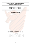
1-4. MOTHERBOARD LAYOUT.
8
ENDAT-D2550 USERS MANUAL
UNICORN COMPUTER CORP.
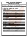
Chapter 2. Setting up the Motherboard
2-1. Connectors / Headers and Jumpers
Connectors Overview:
Function
PS/2 MS/KB Connectors
Cooling Fan Connector
ATX Power Supply Connector
USB 0/1, 2/3 Port
LAN Port
SATA Connector
DDR3 RAM Socket
CRT Output Connector
COM1,2 Connector
COM3 Connector
HD Audio Speaker Output
18/24 bit LCD Panel Connector
PCI Slot
Mini PCI-E Socket
SIM Card Socket
Battery Socket
Connectors
CN1
FAN1, FAN2
ATX1
CN9, CN11
CN9, CN11
SATA1, SATA2
DIMM1
COMVGA1
CN5
COMVGA1
CN13
LVDS1
PCI1
MPCIE1
SIM1
BAT1
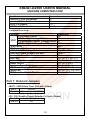
Box Headers, Pin Headers Overview:
Function
eDP Port Header
EDID Panel
Printer Port Box Header
COM 4, 5 ,6 Port Box Header
USB 4, 5, 6, 7 Port Header
PS/2 Mouse/KB Pin Header
External PS/2 Device Header
SM BUS Pin Header
Connectors
J12
JP4
LPT1, LPT2
CN8, CN2, CN6
J6, J7, J11
J1
JKBMS1
SMB1
9
ENDAT-D2550 USERS MANUAL
UNICORN COMPUTER CORP.
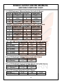
Function
Line-Out, CD-In Pin Header
Line-In、MIC-In Pin Header
SPDIF Pin Header
DIGITAL I/O Pin Header
Connectors
J8
J9
J10
J4, J3
Jumpers Overview:
Function
LCD Voltage Select
LCD Backlight Voltage Select
LVDS1
LCD Backlight Control Voltage Select
LCD Backlight Voltage (for +5V)
Clear CMOS
PS2 Power Selector
COM1/2/3/4/5/6 Voltage Selector
USB Port7 share to Mini PCIe slot
Header for Case Panel
HDD LED
External Speaker
Buzzer On/Off
Hardware Reset Switch
ATX Power Supply On/Off Switch
Power LED
WDT Function Enable/Disable
Connectors
JP8
JP6
JP7
JP10
JBAT1
JP2,
JP3, JP5, JP1
JUSBP7
JP9
JP9: Pin 1(-), Pin 2(+)
JP9: Pin 3(-), Pin 6(+)
JP9: Pin 4, Pin 5
JP9: Pin 7, Pin 8
JP9: Pin 9, Pin 10
JP9: Pin 11(-), Pin 12(+)
JP9: Pin 13, Pin 14
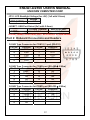
Part 1: Onboard Jumpers
JBAT1: CMOS Data Clear (1x3 with 2.0mm)
Pin 1 *
Normal
Pin 1-2
Close for clear CMOS
JP2: PS2 Standby Power Selector (1x3 with 2.0mm)
Pin 1-2 *
+5Vsb
Pin 2-3
+5V
10
ENDAT-D2550 USERS MANUAL
UNICORN COMPUTER CORP.
J1: PS/2 Keyboard / Mouse Header (2x5 with 2.54mm)
Pin No. Signal (KB)
Pin No.
Signal (MS)
1
KB Data
2
MS Data
3
KEY
4
KEY
5
GND
6
GND
7
+5V(DC)
8
+5V(DC)
9
KB_CLK
10
MS_CLK
JKBMS1: External PS/2 Device Header (2x7 with 2.0mm)
Pin No. Signal (KB)
Pin No.
Signal (MS)
1
MS Data Out
2
KB Data Out
3
MS Data In
4
KB Data In
5
MS CLK Out
6
KB CLK Out
7
MS CLK In
8
KB CLK In
9
KEY
10
KEY
11
+5V(DC)
12
+5V(DC)
13
GND
14
GND
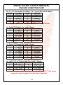
JP3, JP5, JP1: COM Port Voltage Selector (2x6 with 2.0mm)
Voltage
+12V(DC)
R.I. *
+5V(DC)
JP3 (COM1)
1-2
3-4
5-6
JP3 (COM2)
7-8
9-10
11-12
JP5 (COM3)
1-2
3-4
5-6
JP5 (COM4)
7-8
9-10
11-12
JP1 (COM5)
1-2
3-4
5-6
JP1 (COM6)
7-8
9-10
11-12
JP6: LCD Backlight Voltage Select (1x3 with 2.0mm)
Voltage
+5V *
+12V
JP6 (LVDS1)
1-2
2-3
JP7: LCD Backlight Control Voltage Select (1x3 with 2.0mm)
Voltage
+3.3V *
+5V
JP7 (LVDS1)
1-2
2-3
JP8: LCD Voltage Select (2x3 with 2.0mm)
Voltage
+3.3V *
+5V
JP8 (LVDS1)
1-2
3-4
11
+12V
5-6
ENDAT-D2550 USERS MANUAL
UNICORN COMPUTER CORP.
JP10: LCD Backlight Voltage (for +5V) (1x2 with 2.0mm)
Voltage
JP10 (LVDS1)
+5V
JUSBP7: USB Port Select (2x3 with 2.0mm)
J11 USB 7 Header
Mini PCIE Slot*
JUSB7
1-3,2-4
3-5,4-6
Notice: JUSBP7 sets USN PORT7 as PCIe slot or USB Header.
Part 2: Onboard Connectors and Headers
D-SUB Type Connector for COM1,2,3 port (RS-232)
Pin No.
Function
Pin No.
Function
1
DCD
6
DSR
2
RXD
7
RTS
3
TXD
8
CTS
4
DTR
9
RI
5
GND
D-SUB Type Connector for COM2 port (RS-485 2 Wire)
Pin No.
Function
Pin No.
Function
1
Data –
6
NA
2
Data +
7
NA
3
NA
8
NA
4
NA
9
NA
5
NA
D-SUB Type Connector for COM2 port (RS-422 4 Wire)
Pin No.
Function
Pin No.
Function
1
–TXD
6
NA
2
+RXD
7
NA
3
+TXD
8
NA
4
–RXD
9
NA
5
NA
12
ENDAT-D2550 USERS MANUAL
UNICORN COMPUTER CORP.
CN8, CN2, CN6: COM4 ~COM6 port Box Headers (2x5 with 2.54mm)
Pin No.
Function
Pin No.
Function
1
DCD
6
DSR
2
RXD
7
RTS
3
TXD
8
CTS
4
DTR
9
RI
5
GND
10
N.C.
LPT1, LTP2: Printer Port Box Header (2x13 with 2.0mm)
Pin No. Description
Pin No.
Description
1
STB#
10
ACK#
2
PD0
11
BUSY
3
PD1
12
PE
4
PD2
13
SLCT
5
PD3
14
AFD#
6
PD4
15
ERR#
7
PD5
16
INIT#
8
PD6
17
SLIN#
9
PD7
18-25
GND
J1: PS/2 Keyboard / Mouse Header (2x5 with 2.54mm)
Pin No. Signal (KB)
Pin No.
Signal (MS)
1
KB Data
2
MS Data
3
KEY
4
KEY
5
GND
6
GND
7
+5V(DC)
8
+5V(DC)
9
KB_CLK
10
MS_CLK
JKBMS1: External PS/2 Device Header (2x7 with 2.0mm)
Pin No. Signal (KB)
Pin No.
Signal (MS)
1
MS Data Out
2
KB Data Out
3
MS Data In
4
KB Data In
5
MS CLK Out
6
KB CLK Out
7
MS CLK In
8
KB CLK In
9
KEY
10
KEY
11
+5V(DC)
12
+5V(DC)
13
GND
14
GND
13
ENDAT-D2550 USERS MANUAL
UNICORN COMPUTER CORP.
J6, J7, J11: Pin Header for USB 4, 5, 6, 7 ports (2x5 with 2.54mm)
Pin No.
Function
Pin No.
Function
1
USB_VCC
2
USB_VCC
3
USBD44
USBD55
USBD4+
6
USBD5+
7
USB_GND
8
USB_GND
9
KEY
10
USB_GND
Notice: JUSBP7 sets USN PORT7 as PCIe slot or USB Header.
J4: Digital I/O Header (2x7 with 2.0mm)
Pin No.
Function
Pin No.
Function
1
+5V
2
+5V
3
DIO-OUT0
4
DIO-IN0
5
DIO-OUT1
6
DIO-IN1
7
DIO GND
8
DIO GND
9
DIO-OUT2
10
DIO-IN2
11
DIO-OUT3
12
DIO-IN3
13
+3.3V
14
+3.3V
J3: Digital I/O Header (2x7 with 2.0mm)
Pin No.
Function
Pin No.
Function
1
+5V
2
+5V
3
DIO-OUT4
4
DIO-IN4
5
DIO-OUT5
6
DIO-IN5
7
DIO GND
8
DIO GND
9
DIO-OUT6
10
DIO-IN6
11
DIO-OUT7
12
DIO-IN7
13
+3.3V
14
+3.3V
J8: LINE-OUT & CD-IN Header (2 x 4 with 2.54mm)
Pin No.
Signal (KB)
Pin No.
Signal (MS)
1
LINE_OUT_L
2
CD_IN_R
3
JACK_DETECT
4
GND_AUD
5
GND_AUD
6
GND_AUD
7
LINE_OUT_R
8
CD_IN_L
Notice: Please connect the jack detect pin to “GND_AUD” if the actual
connector cannot support the jack detect function!
14
ENDAT-D2550 USERS MANUAL
UNICORN COMPUTER CORP.
J9: LINE-IN & MIC-IN Header (2 x 4 with 2.54mm)
Pin No.
Signal (KB)
Pin No.
Signal (MS)
1
LINE_IN_R
2
MIC_ R
3
JACK_DETECT
4
JACK_DETECT
5
GND_AUD
6
GND_AUD
7
LINE_IN_L
8
MIC_ L
Notice: Please connect the jack detect pin to “GND_AUD” if the actual
connector cannot support the jack detect function!
J10: SPDIF Header (1 x 5 with 2.54mm)
Pin No.
Signal (KB)
Pin No.
Signal (MS)
1
+5V
4
GND
2
N.C
5
SPDIF-IN
3
SPDIF-OUT
SMB1: SM BUS Header (1 x 5 with 2.54mm)
Pin No.
Signal (KB)
Pin No.
Signal (MS)
1
SMB_CLK
4
SMB_DATA
2
+3.3V
5
GND
3
IR_RX
FAN1, FAN2: Cooling Fan Connector
Pin No.
Function
1
GND
2
+12V
3
Sensor Pin
ATXPWR: ATX Power connector
15
ENDAT-D2550 USERS MANUAL
UNICORN COMPUTER CORP.
LVDS: Single LVDS (18/24 bit only, 1.25mm)
MB: DF-13A-40DP-1.25V / Map: DF13-40DS-1.25C
Pin No.
1
3
5
7
9
11
13
15
17
19
21
23
25
27
29
31
33
35
37
39
Signal
VBL
GND
DISP.ON/OFF
LCD POWER
GND
Odd 0+
Odd 1+
Odd 2+
Odd 3+
Odd CLK+
GND
Pin No.
2
4
6
8
10
12
14
16
18
20
22
24
26
28
30
32
34
36
38
40
N.C
N.C
N.C
N.C
N.C
LCD POWER
GND
GND
VBL
Signal
VBL
GND
GND
LCD POWER
GND
Odd 0Odd 1Odd 2Odd 3Odd CLK KEY
N.C
N.C
N.C
N.C
N.C
LCD POWER
GND
GND
VBL
Please make sure the Pin 1 location before plug-in LCD connector.
Please leave pin 23rd ~ pin 32nd unconnected if the single channel LVDS
function is needed.
Please double check "jumper setting & LCD cable's orientation" before
power-on, any incorrect installation may caused damaged of the LCD.
16
ENDAT-D2550 USERS MANUAL
UNICORN COMPUTER CORP.
2-2. Installing Memory
The DDR3 SO-DIMM sockets of ENDAT-D2550 support up to 4GB memory. The speed of
DDR3 memory can be DDR3-800 or DDR3-1066.
2-3. Shared VGA Memory
The ENDAT-D2550 built-in Intel® GMA3600 graphic engine with DVMT 4.0 up system
memory. The amount of video memory on motherboard determines the number of colors
and the video graphic resolution.
2-4. Watch Dog Timer
Watch dog Timer (WDT) is a special design for system monitoring to secure the
system work normally. WDT has an independent clock from the oscillator and could
set time and clear/refresh WDT counter function. When time is up, WDT will send
hardware RESET signal to reset system.
Timeout Value Range
-1 to 255
-Second or Minute
17
ENDAT-D2550 USERS MANUAL
UNICORN COMPUTER CORP.
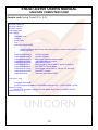
Sample code (using TurboC/C++ 3.0):
#include <stdio.h>
#include <dos.h>
#include <dir.h>
void show_ver();
void main()
{
unsigned int tt;
clrscr();
show_ver();
tt=0;
while((tt==0)||(tt>255))
{
printf("\n\nPlease key in how many seconds you want to reset system (1~255):");
scanf("%d",&tt);
}
outportb(0x2e,0x87);
//Unlock register
outportb(0x2e,0x87);
//Unlock register
outportb(0x2e,0x07);
//set Logic Device number pointer
outportb(0x2f,0x08);
//set Logic Device number
outportb(0x2e,0x30);
//set WDTO active
outportb(0x2f,0x01);
//set reg value active (bit0 =1 active,0 inactive )
outportb(0x2e,0xf5);
//set WDTO Control Mode
outportb(0x2f,0x04);
//set register value (bit3=1: minute. =0: second)
outportb(0x2e,0xf6);
//set WDT Counter
outportb(0x2f,tt);
//set time out value of WDT
}
void show_ver()
{
unsigned char tmp0;
printf("Designed by attila of UNICORN computer corp. \n2012/08/29 release
version:1.0a\n");
printf("This program is design for test Watch Dog Timer for ENADT-D2550
(W83627UHG).\n");
}
18
ENDAT-D2550 USERS MANUAL
UNICORN COMPUTER CORP.
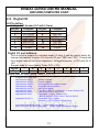
2-5. Digital I/O
J4 Pin define:
J4: Digital I/O Header (2x7 with 2.0mm)
Pin No.
Function
Pin No.
Function
1
+5V
2
+5V
3
DIO-OUT0
4
DIO-IN0
5
DIO-OUT1
6
DIO-IN1
7
DIO GND
8
DIO GND
9
DIO-OUT2
10
DIO-IN2
11
DIO-OUT3
12
DIO-IN3
13
+3.3V
14
+3.3V
Digital I/O port address:
This function is support by onboard super I/O chip; it can be control easily by
change the register of super I/O chip via I/O port “2Eh” and “2Fh”. Please see
the sample code of below for implement. Voltage tolerance: +/- 5% with 0V to
+5V.
Sample code for input (using Turbo C/C++ 3.0):
bit No
7
6
5
4
3
2
1
0
DIO-I3
DIO-I2
DIO-I1
DIO-I0
NA
NA
NA
NA
Map
Sample code for input (using Turbo C/C++ 3.0)
#define input_port 0x2f // Digital input data port
Unsigned char read_data;
outportb(0x2e,0x87);
//Unlock register
outportb(0x2e,0x87);
//Unlock register
outportb(0x2e,0x07);
//set Logic Device number pointer
outportb(0x2f,0x08);
//set Logic Device number
outportb(0x2e,0x30);
//set Device Active
outportb(0x2f,0x02);
// set Bit 1 =GPIO5 ; 0=Inactive / 1= Active Default: 03h
outportb(0x2e,0xE0);
// set GPIO Output / Input Port
outportb(0x2f,0xF0);
// 0=Output/ 1=Input ; Default: F0h
// Bit 0~3 DIO-O0~ DIO3 / Bit4~7 DIO-I0~DIO-I3.
outportb(0x2e,0xF1);
//Read DIO-Input register.
//Bit4~Bit7 = DIO-I0~DIO-I3.(Read Only)
read_data=inportb(input_port); // Read digital input data
printf("DIO-Input=%02X\n",read_data); //Show digital input data on screen
19
ENDAT-D2550 USERS MANUAL
UNICORN COMPUTER CORP.
Sample code for output (using Turbo C/C++ 3.0):
bit No
7
6
5
4
3
2
NA
NA
NA
NA
DIO-O3
DIO-O2
Map
1
0
DIO-O1
DIO-O0
Sample code for output (using Turbo C/C++ 3.0)
outportb(0x2e,0x87);
outportb(0x2e,0x87);
outportb(0x2e,0x07);
outportb(0x2f,0x08);
outportb(0x2e,0x30);
outportb(0x2f,0x03);
outportb(0x2e,0xE0);
outportb(0x2f,0xF0);
outportb(0x2e,0xE1);
outportb(0x2f,0xnm);
//Unlock register
//Unlock register
//set Logic Device number pointer
//set Logic Device number
//set Device Active
// set Bit 1 =GPIO5 ; 0=Inactive / 1= Active Default: 03h
// set GPIO Output / Input Port
// 0=Output/ 1=Input
// Bit 0~3 DIO-O0~ DIO3 / Bit4~7 DIO-I0~DIO-I3.
//Read DIO-Input register.
// n=DIO-I0~DIO-I3 / m=DIO-O0~DIO-O3.
Bit3~Bit4 = DIO-I0~DIO-I3.(Read Only)
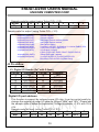
J3 Pin define:
J3: Digital I/O Header (2x7 with 2.0mm)
Pin No.
Function
Pin No.
Function
1
+5V
2
+5V
3
DIO-OUT4
4
DIO-IN4
5
DIO-OUT5
6
DIO-IN5
7
DIO GND
8
DIO GND
9
DIO-OUT6
10
DIO-IN6
11
DIO-OUT7
12
DIO-IN7
13
+3.3V
14
+3.3V
Digital I/O port address:
This function is support by onboard super I/O chip; it can be control easily by
change the register of super I/O chip via I/O port “4Eh” and “4Fh”. Please see
the sample code of below for implement. Voltage tolerance: +/- 5% with 0V to
+5V.
Sample code for input (using Turbo C/C++ 3.0):
bit No
7
6
5
4
3
2
1
0
DIO-I7
DIO-I6
NA
NA
NA
NA
DIO-I5
DIO-I4
Map
20
ENDAT-D2550 USERS MANUAL
UNICORN COMPUTER CORP.
Sample code for input (using Turbo C/C++ 3.0)
#define input_port 0x4f // Digital input data port
Unsigned char read_data;
outportb(0x4e,0x87);
//Unlock register
outportb(0x4e,0x87);
//Unlock register
outportb(0x4e,0x07);
//set Logic Device number pointer
outportb(0x4f,0x07);
//set Logic Device number
outportb(0x4e,0x2A);
//set GOIP Function
outportb(0x4f,0xFC);
//set GP10~GP17
outportb(0x4e,0x30);
//set Device Active
outportb(0x4f,0x01);
// set Bit 1 = Active; 0=Disable
outportb(0x4e,0xF0);
// set GPIO Output / Input Port
outportb(0x4f,0xC3);
// 0=Output/ 1=Input
//Bit 2~5 DIO-O4~ DIO-O7.
//Bit 0,1,6,7 DIO-I4~DIO-I7.
outportb(0x4e,0xF1);
//Read DIO-Input register.
outportb(0x4f,0xnm);
//Bit 2~5 DIO-O4~ DIO-O7.
//Bit 0,1,6,7 DIO-I4~DIO-I7..(Read Only)
read_data=inportb(input_port); // Read digital input data
printf("DIO-Input=%02X\n",read_data); //Show digital input data on screen
Sample code for input (using Turbo C/C++ 3.0):
bit No
7
6
5
4
3
NA
NA
DIO-O7
DIO-O6
DIO-O5
Map
2
1
0
DIO-O4
NA
NA
Sample code for output (using Turbo C/C++ 3.0)
outportb(0x4e,0x87);
outportb(0x4e,0x87);
outportb(0x4e,0x07);
outportb(0x4f,0x07);
outportb(0x4e,0x2A);
outportb(0x4f,0xFC);
outportb(0x4e,0x30);
outportb(0x4f,0x01);
outportb(0x4e,0xF0);
outportb(0x4f,0xC3);
outportb(0x4e,0xF1);
outportb(0x4f,0xnm);
//Unlock register
//Unlock register
//set Logic Device number pointer
//set Logic Device number
//set GOIP Function
//set GP10~GP17
//set Device Active
// set Bit 1 = Active; 0=Disable
// set GPIO Output / Input Port
// 0=Output/ 1=Input
//Bit 2~5 DIO-O4~ DIO-O7.
//Bit 0,1,6,7 DIO-I4~DIO-I7.
//Read DIO-Input register.
// Bit 2~5 DIO-O4~ DIO-O7.
//Bit 0,1,6,7 DIO-I4~DIO-I7..(Read Only)
21
ENDAT-D2550 USERS MANUAL
UNICORN COMPUTER CORP.
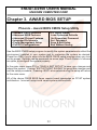
Chapter 3. AWARD BIOS SETUP
Phoenix – Award BIOS CMOS Setup Utility
> Standard CMOS Features
> Advanced BIOS Features
> Advanced Chipset Features
> Integrated Peripherals
> Power Management Setup
> PnP/PCI Configurations
> PC Health Status
Load Optimized Defaults
Set Supervisor Password
Set Password
Save & Exit Setup
Exit Without Saving
Use the BIOS CMOS setup program to modify the system parameters to reflect the
environment installed in your system and to customize the system as desired.
Press the <DEL> key to enter into the BIOS CMOS setup program when you turn
on the power. Settings can be accessed via arrow keys. Press <Enter> to choose
an option to configure the system properly.
In the main menu, press F10 or “SAVE & EXIT SETUP” to save your changes and
reboot the system. Choose “EXIT WITHOUT SAVING” to ignore the changes and
exit the setup procedure. Pressing <ESC> at anywhere during the setup will return
to the main menu.
All of the above CMOS BIOS items require board knowledge on PC/AT system
architecture. Incorrect setup could cause system malfunctions.
22
ENDAT-D2550 USERS MANUAL
UNICORN COMPUTER CORP.
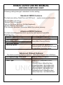
Following setting belongs to standard function setting:
Standard CMOS Features
The features setting Data/Time and SATA port 、system memory Information.
˙System Date (mm:dd:yy) .
˙System Time (hh:mm:ss).
˙Halt On (All Error, No Error, All, But Keyboard).
˙System Memory Information
This submenu provides information about the system memory.
Advanced BIOS Features
The features setting system boot-up priority and keyboard operation、
BIOS Security.
Hard Disk Boot Priority
Select Hard Disk Device Priority.
USB Boot Priority
Select USB Device Priority.
First Boot Device
Select Boot Device Priority.
Second Boot Device
Third Boot Device
Security Option
Select whether the password is
required every time the system boots
or only when you enter setup.
Advanced Chipset Features
The features setting displays devices、LCD panel Support and LAN Boot.
PCI Express Root Port Func
Boot On LAN1/2 Support.
Select Active LFP
LVDS Panel Support.
Panel Type
Select LCD (Integrated LVDS)
resolution.
640x480x18bit, 800x600x18bit,
1024x768x18bit, 1024x768x24bit,
1366x768x18bit, 1366x768x24bit,
800x480x18bit, 1024x600x18bit,
1280x600x18bit,1280x800x18bit
1280x768x18bit, 1440X900X18bit
23
ENDAT-D2550 USERS MANUAL
UNICORN COMPUTER CORP.
Integrated Peripherals
The features setting IO (serial and parallel port) resources, SATA type and
AUDIO、USB Controller set.
OnChip IDE Device
>> SATA Mode
SATA Support IDE or AHCI
Onboard Device
>> Intel HD Audio Controller
HD Audio Controller
SuperIO Device
>> Onboard Serial Port 1 / 2
Serial Port 1 & 2
COM2 Support Mode
Support RS232 / 485 /422
COM2 Termination
Termination En/Disable
>> Onboard Parallel Port:
Parallel 1
Onboard Serial Port 3 / 4 / 5 / 6
Serial Port 3 & 4 & 5 & 6
Serial Port 3 / 4 / 5 / 6 Use IRQ:
Serial Port 3 & 4 & 5 & 6 IRQ
Watch Dog Timer Select
Enable WDT Function.
PWRON After PWR-Fail:
AC power loss status
Power Management Setup
The features setting System power management mode and Wake UP function.
ACPI Function
ACPI Suspend Type
Support S1 , S3
USB KB Wake-Up From S3
USB Key board & Mouse Wake-Up.
Resume by Alarm
RTC Wake-Up.
PnP/PCI Configurations
The features setting init display First and System IRQ Resources.
Select First Boot Display for Onboard
Init Display First
or PCI Device.
Set System IRQ Resources for Auto
Resources Controlled By
or Manual
Set System IRQ Resources by
IRQ Resources
Manual.
24
ENDAT-D2550 USERS MANUAL
UNICORN COMPUTER CORP.
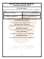
PC Health Status
The features Show System temperature、temperature protection 、Fan speed 、
voltage.
When the CPU temperature exceeds
Shutdown Temperature
the set, the system will automatically
shut down.
When the CPU temperature exceeds
CPU Warning Temperature
the set, the system will issue a
warning sound.
Load Optimized Defaults
The features Load BIOS default setting.
Set Supervisor Password
The features Set BIOS setup administrator password.
Set User Password
The features Set BIOS setup user password.
Save & Exit Setup
The features save BIOS setting and exit BIOS setup
Exit Without Setup
The features not save BIOS setting and exit BIOS setup
25
ENDAT-D2550 USERS MANUAL
UNICORN COMPUTER CORP.
Chapter 4. VGA, LVDS and drivers
4-1.
Graphic controller Feature
The ENDAT-D2550 integrated a high performance Intel® GMA3600 GFX engine
with Intel® DVMT 4.0 technology. The Intel® GMA3600 offering the 3D
enhancements enable greater flexibility and scalability. Improved GFX engine
support Microsoft DirectX 10, OpenGL 1.5 on Windows, and OpenGL 2.0 on Linux.
The ENDAT-D2550 integrated graphics device (IGD) delivering cost competitive
3D, 2D and video capabilities. It contains an extensive set of instructions for 3D
operations, 2D operations, motion compensation, overlay, and display control. The
video engines support video conferencing and other video applications. The Intel®
GMA3600 uses a UMA configuration with Intel® DVMT for graphics memory.
The ENDAT-D2550 also has the capability of supporting external graphics
accelerators via the PCI slot but cannot work concurrently with the integrated
graphics device. High bandwidth access to data is provided through the system
memory port.
The build-in Graphics Controller’s main features include:
- High Performance 3D and 2D graphics controller
- Support Microsoft DirectX 10
- Hardware frame buffer compression improves UMA (Unified Memory
Architecture) memory efficiency
- VGA resolution up to 1920 x 1200
- LVDS (Integrated LVDS) resolution up to 1440x900
26
ENDAT-D2550 USERS MANUAL
UNICORN COMPUTER CORP.
4-2.
Driver Utility Installation Guide
1.
When finishing the installation of Windows XP (support 2D graphic only), Vista,
please install the relative Intel® chipsets, display and AUDIO driver manually for
compliance compatibility of hardware environment.
2.
Please contact sales department of UNICORN for Embedded OS user driver
(Linux, Windows CE and Windows XP embedded). All of embedded OS driver
is not be included in any versions of driver CD-ROM from UNICORN.
Please download or check from Intel® web site: www.intel.com for more
information or last versions of driver as needs!
27
ENDAT-D2550 USERS MANUAL
UNICORN COMPUTER CORP.
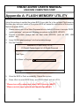
Appendix A: FLASH MEMORY UTILITY
Using this package to update the system BIOS from a disk file to the on board Flash memory.
Be aware any improper update of the system BIOS will cause the malfunction of the system.
Method of update BIOS:
1.
Please contact one of the Sales Representative on behalf of Unicorn to acquire “BIOS
update package”, and process following procedures for the BIOS UPDATE.
2.
Prepare a bootable storage that can boot under MS-DOS, (such as HDD, USB
sticker…etc)
3.
Unzip “BIOS Update package” into the bootable storage.
4.
Run the Flash file.
AwardBIOS FLASH Utility V8.102
C>Phoenix Technologies Ltd. All Rights Reserved
Flash Type –
File Name to Program:
Message:
5.
Once the BIOS is Flash successfully, Reboot the system.
6.
Press <Del> to enter BIOS Setup, save BIOS default and exit <F10>.
* Please turn off system and clear CMOS data by JBAT1.
* Please restart your system and load setup default.
28
ENDAT-D2550 USERS MANUAL
UNICORN COMPUTER CORP.
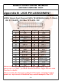
Appendix B: LVDS PIN ASSIGNMENT
LVDS: Single /Dual Channel LVDS (18/24/36/48 bit only, 1.25mm)
MB: DF-13A-40DP-1.25V / Map: DF13-40DS-1.25C
Pin No.
Signal
Pin No.
Signal
1
VBL
2
VBL
3
GND
4
GND
5
DISP.ON/OFF
6
GND
7
LCD POWER
8
LCD POWER
9
GND
10
GND
11
Odd 0+
12
Odd 013
Odd 1+
14
Odd 115
Odd 2+
16
Odd 217
Odd 3+
18
Odd 319
Odd CLK+
20
Odd CLK 21
GND
22
KEY
23
24
Even 0+
Even 0-.
25
26
Even 1+
Even 127
28
Even 2+
Even 229
30
Even 3+
Even 331
32
Even CLK+
Even CLK33
LCD POWER
34
LCD POWER
35
GND
36
GND
37
GND
38
GND
39
VBL
40
VBL
Please make sure the Pin 1 location before plug-in LCD connector.
Please leave pin 23rd ~ pin 32nd unconnected if the single channel LVDS
function is needed.
Please double check "jumper setting & LCD cable's orientation" before
power-on, any incorrect installation may caused damaged of the LCD.
29
ENDAT-D2550 USERS MANUAL
UNICORN COMPUTER CORP.
Appendix C: LIMITED WARRANTY
Standard Two years limited warranty on all our ENDAT series all-in-one
motherboards and embedded board. Products that become defective during the
warranty period shall be repaired, or subject to manufacturer’s option, replaced.
The limited warranty applies to normal proper usage of the hardware and does not
cover products that have been modified or subjected to unusual electrical or
physical stress. Unicorn Computer Corp is not liable to repair or replace defective
goods caused by improper using or use of unauthorized parts. The following
situations will be charged:
1. The products during the warranty but defective caused by improper using or
artificial external pressure and result in the components damages. According to
the damage situation, the manufacturer has the rights to decide to repair or not.
The manufacturer will charge the parts/repair cost and the returning shipping
charge.
2. The products out of warranty will charge the parts/repair cost and the returning
shipping charge as per the repair status.
3. The manufacturer has the rights to decide to repair or not based on the stock of
parts for the products which are phased out of the production.
4. Please e-mail or fax the RMA Service Request Form when have the defective
products.
30
ENDAT-D2550 USERS MANUAL
UNICORN COMPUTER CORP.
RMA SERVICE REQUEST FORM
When requesting RMA service, please fill out this “RMA Service Request Form”.
This form needs to be shipped with your returns. Service cannot begin until we
have this information.
RMA NO.:
Company:
Person to Contact:
Phone No:
Purchase Date :
Fax No. :
Applied Date :
Return Shipping Address:
Model No.
Serial No.
Problem Description
Please specify the following when returning the RMA boards:
(1) Hardware Configuration (2) OS or Software (3) Testing Program
___________________
Authorized Signature
31