1
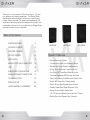
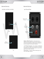
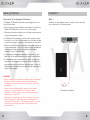
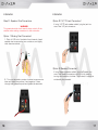
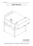
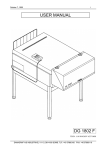
VAS12SUB / VAS15SUB
VAS18SUB
SHAKER SUBWOOFER SYSTEMS
Thank you for your interest in VM Audio products. Our goal
is to enhance your listening experience. The Shaker Series
was designed as the economical solution for a performance
craving, casual consumer. The experts and engineers at VM
Audio have meticulously tested and designed this product with
a reasonable price tag to fit any budget. Let the Shaker Series
maximize the value of your investment.
Table of Contents
SYSTEM FEATURES
3
PACKAGE CONTENTS
5
FEATURES OVERVIEW
5
GETTING STARTED
8
INSTALLATION
9
VAS12SUB
VAS15SUB
VAS18SUB
System Features
• Passive Subwoofer System
MAKING YOUR OWN CONNECTORS
12
• Compact High Output Low Frequency Design
TIPS
14
• Efficient High Power Ribbed Cone Subwoofer
SUBWOOFER CONFIGURATIONS
15
PARALLEL SPEAKER CONNECTIONS
17
TROUBLESHOOTING
19
SPECIFICATIONS
20
LIMITED WARRANTY AGREEMENT
22
• 2” High Force Multi-Layer Copper Voice Coil
• Low Noise CAD Tuned Bass Reflex Enclosure
• Computer Engineered HDF Acoustic Enclosure
• Heavy Duty Aviation Grade Enclosure Carpet Cover
• Sturdy ABS Heavy Duty Cabinet Handle
• Built-In 35-mm Steel Speaker Mount Socket
• Powder Coated Black Steel Subwoofer Grille
• Sturdy Enclosure Black Rubber Feet
• 1/4” TS Jacks and Speakon Inputs with Aux Outputs
• Binding Post Input Speaker Wire Connector
2
3
CAUTION
RISK OF ELECTIC SHOCK
DO NOT OPEN
CAUTION
CAUTION
RISK OF ELECTIC SHOCK
DO NOT OPEN
1.Please read these intructions carefully before attempting
to install and operate this unit.
Safety Precautions
Package
Contents
Your Shaker DJ Subwoofer was carefully packaged to
ensure a safe and secure transport to its destination. Please
review the contents of the package and make sure you have
received all the items included with your system.
2.Please read all instructions as indicated in the User Guide.
VAS12SUB, VAS15SUB, VAS18SUB
3.Keep this User Guide for future reference.
(1) Subwoofer
(1) User Guide
4.Save all packaging in the event the unit needs to be
returned for service or replacement.
5.Heed all warnings, unit can be hazardous if not used
properly or as directed.
Features Overview
6.Ensure to setup your system in a safe and secure manner.
7.Do not expose the unit to rain, moisture, dripping,
splashing or use near water.
8.Do not place objects filled with liquids on the unit.
9.Do not place or install unit near heat sources such as
radiators, heat registers, stoves, amplifiers or other
apparatus that produce heat.
The Shaker DJ Subwoofer Series are easy to operate
systems and were designed for both professional and
consumer DJ use. Please take a few moments to read this
user guide and familiarize yourself with the features.
VAS12SUB, VAS15SUB, VAS18SUB
10. Protect the speaker wires from being walked on or getting
pinched.
11. Use only hardware such as tripods, brackets,
attachments, and other accessories components specified
by VM Audio.
12. Before placing, installing or suspending this loudspeaker
product, inspect all hardware, brackets, surfaces,
cabinets and associated equipment for damage. If a fault
is discovered, it should be corrected immediately.
Woofer
13. Do not attempt to service this unit, refer all servicing to
qualified service personnel.
Ports
Front
4
5
Features Overview
Features Overview
Input Terminal Plate
VAS12SUB, VAS15SUB, VAS18SUB
Speakon Cable
Connectors
Input
Terminal
1/4” TS Jack
Connectors
Rear
Binding
Posts
Speakon Cable Connectors - Two connectors are
featured which are wired in parallel. Use one connector to
connect to the amplifier and use the second connector to
tap into the signal to drive another subwoofer.
35 mm
Pole Socket
1/4” TS Jack Connectors - Two connectors are featured
which are wired in parallel. Use one connector to connect to
the amplifier and use the second connector to tap into the
signal to drive another subwoofer.
Top
6
Binding Posts - Connector accepts banana plugs, bare
wires, and spade connectors.
7
Getting Started
Installation
Subwoofer & Loudspeaker Placement
Step 1
The Shaker DJ Series Subwoofers were designed to sit on
a solid flat surface.
Carefully run the speaker wires or cable from the amplifier
up to the location of the subwoofer.
•Follow the user guide installation procedures to install your
Shaker DJ Subwoofer into your own sound system.
•Place the subwoofer cabinet on a solid level surface where
it cannot be toppled or tilted.
•If a Shaker DJ loudspeaker is to be pole mounted, ensure
the tripod is on a flat solid surface and on a location where
it cannot be toppled or tilted by the audience or personnel.
•When using a Shaker DJ loudspeaker, place the speaker at
or above head level. This is to prevent the high frequencies
from being blocked and getting muffled by obstacles
directly in front of the tweeters.
•Avoid placing full-range loudspeakers in a corner or right
next to a wall to avoid degrading the overall sound quality.
•If loudspeakers are to be placed in locations where large
amounts of reverberations or echoes are produced, such
as gymnasiums and auditoriums, laying carpet or rugs will
help dampen the reflections and improve the overall sound
quality of the system.
CAUTION!
• Before installing this subwoofer product, inspect all hardware,
brackets, surfaces, cabinets and associated equipment
for damage. If a fault is discovered, it should be corrected
immediately.
• Never connect multiple amplifier outputs to the parallel
speakon or 1/4” jack speaker wire connectors at the
same time. This may cause a short and may damage your
equipment or cause a fire.
Subwoofer Installation
• This subwoofer can easily reproduce sound pressure levels
(SPL) loud enough to cause permanent ear damage that
could result in hearing loss. Take great precaution to protect
yourself from prolonged exposure to high output sound
pressure levels.
8
9
Installation
Step 2 - Speaker Wire Connections
WARNING!
To prevent electrical shock hazard, always switch off the
amplifier when making connections to the subwoofer.
Installation
Option 2 (1/4” TS Jack Connection)
If using 1/4” TS jack speaker cable(s), plug the jack into
one of the 1/4” jack connectors.
Option 1 (Binding Post Connection)
1- Strip off 1/2 inch of insulation from the ends of each
speaker wire to expose the two conductors, and tightly
twist the wire strands.
Option 3 (Speakon Connection)
2 - Turn post terminals counter clockwise to expose wire
holes and insert the positive (+) and negative (-) wires
through their respective post and tighten the terminals.
10
If using Speakon speaker cable(s), plug the Speakon into
one of the Speakon connectors and lock it into place by
turning the connector clockwise. Once locked, it cannot be
accidentally disconnected.
11
Making Your Own Connectors
1/4” TS Jack Connectors
Speakon Connectors
1.Strip off 1/2 inch of insulation from the ends of each
speaker wire to expose the two conductors, and tightly
twist the wire strands.
1.Strip off 1/2 inch of insulation from the ends of each
speaker wire to expose the two conductors, and tightly
twist the wire strands.
2.Disassemble the 1/4” TS Jack connector by separating
the shield barrel from the tip sleeve and insert the
speaker wire through the shield barrel.
2.Disassemble the Speakon connector by separating the
bushing from the housing and insert the speaker wire
through the bushing and chuck.
3.Solder the negative (-) wire to the sleeve and the
positive (+) wire to the tip.
4.Assemble the 1/4” TS Jack connector by attaching the
shield barrel back to the tip sleeve.
12
Making Your Own Connectors
3.Remove the insert from
the housing and connect
the negative (-) wire to
the 1- terminal as well
as the positive (+) wire to
the 1+ terminal.
4.Assemble the Speakon connector by attaching the
bushing back to the housing.
13
Tips
Subwoofer Configurations
Subwoofer Power Requirements
Single Subwoofer Operation
The following guidelines will assist you in selecting the
appropriate amplifier for your subwoofer(s) to maintain a
safe level of operation.
•For clear, high quality performances where distortion
should be at its minimum, the subwoofer(s) should be
powered with an amplifier capable of delivering twice its
power rating. (ex. Classical, Jazz, Instrumental, etc)
CH 1 & CH 2
Bridged
•For non-distorted high output performances where the
music is at a constant beat, the subwoofer(s) should be
powered with an amplifier with the same power rating.
•For musical performances where distorted material will
be allowed to be played back, an amplifier with half the
power rating is recommended for safe operation.
Speaker Wires
When running long lengths of speaker wires, it is
recommended that higher gauge wire (12 Ga or higher) is
always used. Using speaker wires lower than 12 Ga limits
the amplifier from delivering full power to the subwoofer(s),
which may result in poor sound performance.
Equipment Protection
Stereo Subwoofer Operation
CH 1
CH 2
•Always optimize the signal levels throughout the system
to avoid overdriving your system and the subwoofer(s).
•When possible, use a low pass electronic crossover to
protect the main loudspeakers from low frequency notes
and protect the system.
•Keep in mind the electrical limitations of your system.
•Always avoid feedback.
Left
14
Right
15
Subwoofer Configurations
Parallel Subwoofer Connections
Single Loudspeaker & Subwoofer Operation
1/4” TS Jack Plug
Input
CH 1
Output
Subwoofer 1
Input
Subwoofer 2
CH 2
Speakon Quick-Connect
Stereo with Subwoofer Operation
Input
CH 1
CH 2
Bridge Mono
Operation
Output
Subwoofer 1
Left
16
Input
Subwoofer 2
Right
17
Parallel Subwoofer Connections
Troubleshooting
No audio when subwoofer is connected
•
•
•
Daisy Chained Subwoofers
•
•
Make sure the mute is off.
Ensure volume and all gain controls in your system are
turned up.
Check if speaker wire connections have been interrupted
and make sure they have a solid connection to the speaker
terminals on the amplifier and enclosure.
Check if all line level cables are carrying a signal.
Make sure all relevant channels are turned on.
Audio output only on one channel
•
•
•
Make sure sure all relevant channels are turned on.
Check that the mixer console and amplifier are working
properly and do not have a muted channel.
Check speaker wire connections to the silent channel and to
the corresponding subwoofer and make sure thay are solid.
Distorted output
•
•
•
•
•
Make sure that all signal gains have been adjusted correctly
on the mixing console.
Check if all signal levels on the signal processor(s) have been
set to the correct levels.
Ensure input signal to the amplifier is not higher than the
maximum allowed input level.
Make sure that the amplifier outputs are not “clipping”.
Check cable and speaker wire connections and make sure
that they are not electrically shorting out.
Bass output too low
•
18
Speakers wires may not be connected properly. Ensure that
the positive (+) and negative (-) speaker wires are connected
to the positive (+) and negative (-) terminals on the amplifier
and on the speaker terminal on the enclosure.
19
Specifications
Specifications
VAS12SUB
VAS18SUB
Loudspeaker Type
Low Frequency Transducer
Loudspeaker Type
Low Frequency Transducer
Low Frequency Driver
12” High Output Subwoofer
Low Frequency Driver
18” High Output Subwoofer
Frequency Response
35 Hz - 300 Hz
Frequency Response
35 Hz - 300 Hz
Total Power (RMS)
500 Watts
Total Power (RMS)
1000 Watts
Total Power (Peak)
1000 Watts
Total Power (Peak)
2000 Watts
Impedance
8 Ohms
Impedance
8 Ohms
Sensitivity
98 dB
Sensitivity
103 dB
Enclosure Construction
Heavy Duty HDF Wood
Enclosure Construction
Heavy Duty HDF Wood
Enclosure Finish
Aviation Grade Carpet Cover
Enclosure Finish
Aviation Grade Carpet Cover
Input Connectors
Speakon / 1/4” Jack / Binding Post
Input Connectors
Speakon / 1/4” Jack / Binding Post
Net Weight
29.4 Lbs / 13.34 kg
Net Weight
59.0 Lbs / 26.76 kg
Dimensions (W x H x D)
16.73” x 18.70” x 13.78”
Dimensions (W x H x D)
21.85” x 24.21” x 17.72”
VAS15SUB
Loudspeaker Type
Low Frequency Transducer
Low Frequency Driver
15” High Output Woofer
Frequency Response
35 Hz - 300 Hz
Total Power (RMS)
750 Watts
Total Power (Peak)
1500 Watts
Impedance
8 Ohms
Sensitivity
102 dB
Enclosure Construction
Heavy Duty HDF Wood
Enclosure Finish
Aviation Grade Carpet Cover
Input Connectors
Speakon / 1/4” Jack / Binding Post
Net Weight
38.1 Lbs / 17.28 kg
Dimensions (W x H x D)
19.88” x 21.85” x 15.96”
20
21
Limited Warranty Agreement
Your product is covered by a limited warranty by VM Audio as
established below:
Electronics Limited Warranty
Products purchased from an Authorized VM Audio Dealer are
warranted to be free of defects in material and workmanship
for one (1) year from the date of original purchase under
normal usage. Products that are identified as “refurbished”
have a limited warranty of ninety (90) days from the date of
original purchase. Dated proof of purchase (original receipt
or invoice) will be required for all warranty claims. In the
unlikely event that you experienced a manufacturing defect or
malfunction during the warranty period, VM Audio will repair
the defective product or replace with the same or equivalent
product if the same item is not available or discontinued.
Replacement product may have superficial blemishes or
scratches that do not affect the performance of the product.
This warranty is only intended and valid for the original
purchaser and cannot be extended to subsequent owners. Any
applicable implied warranties are limited to the period of the
expressed warranty starting from the original purchase date.
No warranties, expressed or implied, will be accepted after the
previously listed periods. Exclusions may apply; please check
your local state laws.
Instructions for Claiming Warranty Service
If you should require warranty service, please return the
product to the Authorized VM Audio Dealer you originally
purchased the item for an experienced and speedy claim of
your warranty service. Contact VM Audio directly to find the
Authorized Dealers nearest you.
In the case the defective merchandise needs to be returned
to VM Audio, please contact us and a Return Merchandise
Authorization (RMA) number will be assigned. It is important
to pack all defective items in the original packaging to prevent
damages from shipping, and be sure to write the RMA number
clearly on the outside of the box for faster processing. Do
not include non-defective items as it is not necessary and will
increase your shipping costs.
22
Limited Warranty Agreement
Include a copy of the original receipt or invoice with the
purchase date, dealer’s name, customer’s name and invoice
number clearly visible. Manufacturing date may be used if no
proof of purchase is provided. The customer will pay to ship the
defective product; COD will not be accepted.
Please follow the above instructions carefully to prevent voiding
your warranty.
Your Warranty Service Does Not Cover the Following:
- Products not purchased from an Authorized VM Audio
Dealer
- Damages from poor installation by not following the included
instruction manual.
- Damages due to excessive moisture, heat and other
elements from improper care.
- Evidence of tampering or repair by non-authorized personnel.
- Products not issued an RMA number.
- Damage during freight from poor packaging or handling.
- Return shipping on non-defective items.
Warranty Turnaround Time
It is VM Audio’s goal to turnaround the merchandise in a timely
fashion of 1 week. Unexpected delays may occur due to repair
parts or replacement shortage.
International Warranty
Please check with your Authorized International VM Audio
Dealer or distributor for specific warranty policies and process
for your country.
23