1
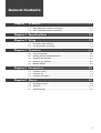
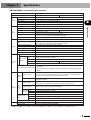
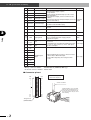
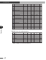
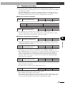
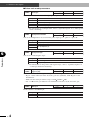
YAMAHA SINGLE-AXIS ROBOT
CONTROLLER
SRCD/SRCP
PulseTrain Mode
User’s Manual
ENGLISH
E
E86-Ver. 2.01
Introduction
Thank you for purchasing the YAMAHA robot controller SRCP/SRCD series.
The SRCP/SRCD series controller can be used with a YAMAHA single-axis robot of the
PHASER series or FLIP-X series to perform various tasks in FA (factory automation)
applications such as pick and place work on conveyor lines, semiconductor manufacturing equipment and assembly machines.
This supplementary manual explains wiring methods, specifications and operation parameters needed for the SRCP/SRCD series to control the robot position by pulse train input
from the host unit.
■ For information on how to install the SRCP/SRCD series controller and safety precautions, see the "YAMAMA Single-axis Controller SRCP Series User's Manual" or
"YAMAMA Single-axis Controller SRCD Series User's Manual" (hereafter called "Controller User's Manual"). Before using the SRCP/SRCD series controller, first read the
controller user's manual and this supplementary manual carefully until you thoroughly
understand the contents and can comply with all instructions.
■ Even after reading this manual, keep it in a safe, easily accessible location so it can be
referred to when needed.
■ The contents of this manual are subject to change without prior notice.
■ Every effort was made to ensure the contents of this manual are complete. However,
please contact us if errors, ambiguities or possible trouble points are found.
■ This manual does not guarantee use of industrial rights or other rights, and does not grant
or concede rights to their use. YAMAHA cannot be held liable for any problems regarding
industrial rights that might occur through use of the contents in this manual.
i
MEMO
ii
General Contents
Chapter 1 Overview............................................................. 1-1
1-1
1-2
SRCP/SRCD series functions and features ........................................................ 1-1
Pulse train mode functions and features ........................................................... 1-1
Chapter 2 Specifications .................................................... 2-1
Chapter 3 Setup .................................................................. 3-1
3-1
3-2
Installation and connection .............................................................................. 3-1
I/O specifications and wiring ........................................................................... 3-1
Chapter 4 Operation ............................................................ 4-1
4-1
4-2
4-3
4-4
4-5
Setup for operation .......................................................................................... 4-1
Defining the CW and CCW directions .............................................................. 4-2
Magnetic pole detection ................................................................................... 4-3
Electronic gear function ................................................................................... 4-4
Monitor function .............................................................................................. 4-5
Chapter 5 Parameters ......................................................... 5-1
5-1
5-2
5-3
Parameter setting ............................................................................................. 5-1
Parameter list ................................................................................................... 5-1
Parameter description ...................................................................................... 5-3
Chapter 6 Alarms ................................................................ 6-1
6-1
6-2
6-3
Checking the alarm .......................................................................................... 6-1
Alarm list .......................................................................................................... 6-2
Troubleshooting ................................................................................................ 6-3
i
MEMO
ii
Chapter 1
Overview
1-1
SRCP/SRCD series functions and features
1
■ Variation
Type
Operable robot
SRCP series
SRCP-05, 05A, 10, 10A, 20, 20A
PHASER series
SRCD series
SRCD-05, 05A, 10, 10A, 20, 20A
FLIP-X series
Overview
Series name
* Use a correct combination of robot and controller.
■ Control mode
The following two control modes can be selected by setting a parameter (PRM64: Input
type).
Control mode
Normal mode
Pulse train mode
Description
PRM64
Allows point movement and programmed operation by
custom command input.
0 (Default)
Position control by pulse train input.
1: Phase A / Phase B input
2: Pulse / code input
3: CW / CCW input
* For details on normal mode, refer to the controller user's manual.
* Control mode is switched after restarting the controller.
1-2
Pulse train mode functions and features
■ Return to origin
A custom input for return-to-origin is provided. Each time this is input, the robot moves
and stops at the same origin position after detecting a torque generated when the robot
reaches stroke end.
* On the PHASER series robots, the magnetic poles are simultaneously detected during
return-to-origin.
■ Electronic gear function
This function allows the robot to move at a rate equal to the number of pulses that is
determined by multiplying the input command pulse count by the electronic gear ratio.
This function is effective in the following cases.
• When the pulse output from the host device is insufficient.
• When you want to set an optional movement distance per pulse.
The electronic gear ratio is set by entering a parameter value.
■ Feedback pulse output
Can output position data as differential output.
Allows the host device to detect the robot’s current position in real time.
■ TPB
The TPB programming unit allows:
• Changing parameters
• Checking the alarm history
• Monitoring I/O information
1
1-
MEMO
2
1-
Chapter 2
Specifications
■ SRCP/SRCD series basic specifications
Description
Item
W78 × H250 × D157 mm
Dimensions
1.5 kg
Weight
Basic
specifications Power voltage
AC 200 to 230V ±10%, single phase 50/60Hz
Operating/storage temperature
0 to 40 °C / -10 to 65 °C
Operating humidity
35 to 85 % RH (no condensation)
Control axis
1 axis
Control system
Full-digital software AC servo
Position detection method
Magnetic linear scale
Speed setting
1 to 100% in 1% steps
1 to 100% in 1% steps by acceleration parameter setting
Servo adjustment
Adjustable by parameters (special setting) such as servo gain and current limit.
ROM
256KB (with CPU)
128KB with lithium battery backup (battery life: 5 years)
RAM
Retains programs, point data, parameters and error records.
Number of program steps
Up to 3000 steps in total; 255 steps per program
Number of programs
100
Number of points
1000
Number of multitasks
4
Point teaching method
MDI (coordinate value input), remote teaching, direct teaching
Normal mode
Robot operation by dedicated command input
Type
I/O
Command
mode
Resolver
Automatic setting based on robot type and payload
Acceleration setting
Memory
2
Specifications
Axis
control
SRCD series
SRCP series
Series name
Pulse Train
Mode
Mode
Resolution
Frequency
Serial communication (RS-232C)
1: phase A/phase B, 2: pulse/code, 3: CW / CCW
One of the above should be selected.
Line driver (+5V)
1µm
16384 pulses/rev
Maximum 2 Mpps (line driver)
1: Data transmit/receive, parameter setting and robot operation by communication
commands
2: Data transmit/receive, parameter setting, point teaching and robot operation by TPB
(option)
Sequence input
Absolute movement (ABS-PT), relative movement (INC-PT), auto program run (AUTOR), step run (STEP-R), return-to-origin (ORG-S), reset (RESET), servo ON (SERVO),
interlock (LOCK), general-purpose input: 8 points (DI0 to 7)
Sequence output
Ready (READY), busy (BUSY), End (END), general-purpose output: 5 points (DO0 to 4),
open collector output
Sequence input
Servo ON (SERVO), return-to-origin input (ORG-S), pulse inhibit (INH), deviation clear
(PCLR), alarm reset (RESET), general-purpose input: 8 points (DI0 to 7)
Sequence output
Alarm (ALM), servo ready (SRDY), positioning completion (IN-POS), general-purpose
output: 5 points (DO0 to 4), open collector output
Normal
mode
I/O
interface
Pulse
train
mode
Name
Command
pulse input Type
Mode
Feedback pulse
output
Function
PULS+, PULS-, DIR+, DIROne of the above should be selected.
Line driver (+5V)
Name
PA+, PA-, PB+, PB-, PZ+, PZ-, PZM+*, PZM-*
Type
phase A/phase B
Mode
Line driver (+5V)
Power supply for sequence I/O
External DC +24V input for sequence input/output
Protective function
Overcurrent, overload, broken wire detection, runaway check, etc.
Network option
CC-Link, DeviceNet, EtherNet, PROFIBUS
* PZM+ and PZM- are available only for the SRCP series. These are unavailable for the SRCD series.
1
2-
MEMO
2
2-
Chapter 3
Setup
3-1
Installation and connection
For information on how to install the controller and to connect it to the power supply and
robot, refer to the controller user's manual.
3-2
I/O specifications and wiring
■ I/O signal table
[EXT.CN]
No. Signal name
Meaning
Description
1
EMG1
2
EMG2
3
24V
Signal input for
4
24G
sequence I/O
DC 24V input terminals for sequence input.
Connect the positive (+) polarity of a DC 24 V power
supply to "24V", and the negative (-) polarity to "24G".
Emergency
stop input
Power supply
input for I/O
Mating connector number : 733-104 (WAGO); supplied
On-board connector number : 733-364
[I/O.CN]
No. Signal name
Meaning
Description
Type
A1
B1
(NC)
(Reserved)
Do not use.
Deviation clear input
When ON, ignores command pulses and clears
deviation counter.
Requires an input pulse of at least 1ms duration. Input
pulse shorter than this may not clear counter.
–
A2
B2
PCLR
A3
ORG-S
Switching from OFF to ON starts return-to-origin.
Stops if switched to OFF. Command pulse inputs are
Return-to-origin input ignored during return-to-origin.
This input also detects the magnetic poles
simultaneously with return-to-origin. (only on PHASER
series)
B3
RESET
Alarm reset input
Alarm is reset at ON,
Alarm cannot be reset if ON duration is shorter than
130ms.
A4
SERVO
Servo ON input
Servo turns on at ON and turns off at OFF.
At ON, obeys command pulse if SERVO input is ON
(servo-ON).
When switched to OFF, stops at that point and ignores Sequence
input
command pulses.
Can be set to enable/disable by setting PRM69.
(Default setting = disable)
B4
INH
Command pulse
prohibit input
A5
DI0
General-purpose input 0
B5
DI1
General-purpose input 1
A6
DI2
General-purpose input 2
B6
DI3
General-purpose input 3
A7
DI4
General-purpose input 4
B7
DI5
General-purpose input 5
A8
DI6
General-purpose input 6
B8
DI7
General-purpose input 7
General-purpose input: 8 points
No assign function.
1
3-
3
Setup
Use these terminals to trigger an external safety
device (safety enclosure, manual switch, etc.) to stop
the robot immediately.
Emergency stop input 1 Using a relay with load contact capacity of 50mA or
Emergency stop input 2 more is recommended.
Opening the contact between EMG and EMG2 shuts
off the servo power supply, and the status shifts to
"Servo OFF and "Alarm ON".
Type
3-2 I/O specifications and wiring
No. Signal name
Setup
3
A9
DO0
B9
DO1
A10
DO2
B10
DO3
A11
DO4
B11
IN-POS
A12
SRDY
B12
ALM
A13
B13
Meaning
Description
Type
General-purpose output 0
General-purpose output: 5 points
General-purpose output 1 Assign function
Return-to-origin completed output (Can be set with
General-purpose output 2 DO4 and PRM33.)
Servo ON status output (Can be set with DO3 and
General-purpose output 3 PRM46.)
Magnetic pole detection completed output (Can be set Sequence
General-purpose output 4 with DO2 and PRM73.)
output
In-position output
Sets to ON if accumulated pulses in deviation counter
are within ±value of PRM6 setting.
Servo ready output
Turns on at servo-ON if command pulse inputs are
possible.
Alarm output
Turns off in emergency stop or if alarm occurs.
FG
Frame ground
Internally connected to the ground terminal.
FG
A14
B14
GND
Signal ground
Internal signal ground terminal.
This is insulated from power supply (24G) for
sequence I/O signals.
GND
A15
B15
PULS+
PULS-
A16
B16
DIR+
DIR-
A17
PA+
B17
PA-
A18
PB+
B18
PB-
A19
PZ+
B19
PZ-
A20
PZM+*
B20
PZM-*
Command pulse
input
Command direction
input
Feedback pulse
output
Command pulse input terminal. Input voltage should
be 5V±10%.
3 command types selectable with PRM64 (Input type). Pulse input
(1) Phase A / phase B input, (2) Pulse / code input,
(3) CW / CCW input
Outputs feedback pulses (Phase A, Phase B, Phase
Z, Phase ZM) as differential output.
* Phase ZM is output only when using the SRCP
series.
Pulse output
Mating connector number : XG4M-4030-U (OMRON) MIL type
On-board connector number : XG4C-4034
■ Connector pinout
Triangular mark
(connector side)
2
3-
← Left: I/O CN pinout
↓ Below: EXT. CN pinout
3
4
Slotted screwdriver
2
B20
B19
•
•
•
•
•
•
•
•
•
•
•
B3
B2
B1
1
A20
A19
•
•
•
•
•
•
•
•
•
•
•
A3
A2
A1
Terminal numbers are not actually
indicated, but designated from 1 to
4, from the left as viewed from the
front (wire insertion side) as shown
in the drawing.
3-2 I/O specifications and wiring
■ I/O wiring diagram
9
26LS32 or equivalent
% 3&/5
38/6
$
38/6
%
',5
$
',5
%
*1'
$
3$
$
% ',
3$
%
$ ',
3%
$
% ',
3%
%
$ ',
3=
$
% ',
3=
$ 25*6
9
6*
% 5(6(7
$ 6(592
6*
% ,1+
$ ',
26LS31 or equivalent
$ '2
6*
% '2
$ '2
Ȑ
3
Ȑ
%
*1
$
*1
PZM-
%
*1'
%
)*
%
PZM+
% ',
Ȑ
Setup
$ ',
6*
Ȑ
6*
,2&1
% '2
$ '2
% ,1326
$ 65'<
% $/0
$ )*
,2&1
㸠ࠈѸ
'&9
(0*
(0*
9
*
(;7&1
SRCP controller
* In the SRCP/SRCD series, the I/O pins have different functions and meanings in each
control mode.
*1: PZM+ and PZM- are available only for the SRCP series. These are unavailable for the
SRCD series.
3
3-
3-2 I/O specifications and wiring
■ Pulse circuit description
[Line driver input]
The line receiver used here is the
26LS32or equivalent item. A
maximum pulse input of 2Mpps is
allowed here. Use a twisted-pair
cable to make the connection.
Setup
3
* The robot controller's SG must be connected to the pulse train controller's SG .
The SG terminals (pin No. A14 and B14) are isolated from 24G (pin No. 4 of EXT. CN).
Wire each of them securely.
■ Sequence I/O circuit description
Sequence I/O is equivalent to custom and general-purpose I/O in normal mode. For
detailed description of the sequence I/O circuit, refer to section 3-4-2, "I/O circuit and
connection example", in the controller user's manual.
4
3-
3-2 I/O specifications and wiring
■ Signal description
Deviation clear input
(PCLR)
Pin No. B2 (I/O.CN)
Sequence input
[Function]
• At ON ignores input pulses and clears the deviation counter.
* This signal must be ON at least 1ms or more. A pulse shorter than this may not clear
the counter.
Return-to-origin input
(ORG-S)
Pin No. A3 (I/O.CN)
Sequence input
Alarm reset input (RESET)
Pin No. B3 (I/O.CN)
Sequence input
[Function]
• Clears the alarm at ON. (Input of 130ms or longer duration is required.)
* Some alarms can only be cleared by turning the power off and then on again.
Servo ON input (SERVO)
Pin No. A4 (I/O.CN)
Sequence input
[Function]
• Servo turns on at ON and pulse inputs are accepted.
* In the PHASER series, a high pitched noise is heard for about 0.5 to 2 seconds after the
first servo-ON input and then the servo turns on. This noise is produced by moving the
robot a small distance in order to acquire information for controlling the robot and is
not an error.
Command pulse inhibit
input (INH)
Pin No. B4 (I/O.CN)
Sequence input
[Function]
• If the servo input is ON, then command pulses are accepted at ON and the robot moves as
to those pulses.
• When this input is set to OFF, the command pulse inputs are disabled, the robot stops and
sets to servo-lock.
• Can be disabled by setting the parameter (PRM69: INH input). (Default setting = disable)
5
3-
3
Setup
[Function]
• Starts return-to-origin at ON and stops at OFF.
• Return-to-origin is performed by stroke-end torque detection method, in which the robot
stops at the same origin position by reversing the movement after striking the mechanical
stopper.
* Do not use with a system that stops during torque detection. Doing so will cause alarms
and in worst cases will damage the motor. When repeating return-to-origin is unavoidable, hold for at least 5 seconds before repeating return-to-origin.
• The return-to-origin direction can be changed with the PRM5 (Return-to-origin direction)
parameter.
* On the PHASER series robots, the magnetic poles are simultaneously detected during
return-to-origin.
* Pulse input is disabled during return-to-origin,
* Always make sure the robot is in stop before performing return-to-origin,
3-2 I/O specifications and wiring
Command pulse input
Command direction input
Pin No. A15, B15, A16, B16 (I/O.CN)
Pulse input
[Function]
• The input type of these signals is changed by setting PRM64 (Input type)
Logic
PRM64 Command pulse format
Input pin
CW direction
CCW direction
A15: PULS+
1
Phase A / Phase B
B15: PULSA16: DIR+
B16: DIRA15: PULS+
Positive
logic
3
2
Pulse code
B15: PULSA16: DIR+
H
B16: DIR-
L
Setup
A15: PULS+
3
CW / CCW
H
B15: PULSA16: DIR+
B16: DIR-
H
A15: PULS+
1
Phase A / Phase B
B15: PULSA16: DIR+
B16: DIRA15: PULS+
Negative
logic
2
Pulse code
B15: PULSA16: DIR+
L
B16: DIRA15: PULS+
3
CW / CCW
L
B15: PULSA16: DIR+
H
L
B16: DIR-
* Change to positive or negative logic with the PRM66 (Input pulse logic) parameter.
* When "phase A / phase B" input is selected, 1×, 2× or 4× are selectable with the
PRM65 (Input pulse evaluation) parameter.
In-position output (IN-POS) Pin No. B11 (I/O.CN)
Sequence output
• Sets to ON when deviation counter accumulated pulses are within the setting by PRM6
(positioning completed pulse).
• Sometimes continually remains ON, when command speed is low or PRM6 is a large
value.
Servo ready output (SRDY) Pin No. A12 (I/O.CN)
Sequence output
• Turns ON with servo input at ON, when command pulse inputs can be accepted.
* Sets to OFF when pulse inputs are prohibited by INH input.
* Sets to OFF while return-to-origin is run by ORG-S input.
Alarm output (ALM)
Pin No. B12 (I/O.CN)
• Sets to OFF when SRCP/SRCD series controller detects an error.
• Sets to OFF during emergency stop.
6
3-
Sequence output
3-2 I/O specifications and wiring
Feedback pulse output
Pin No. A17, B17, A18, B18, A19, B19, A20, B20 (I/O.CN) Pulse output
• Outputs current position information as differential output.
■Pulse output and phase
Output pin
CW direction
CCW direction
A17:PA+
B17:PAA18:PB+
B18:PBA19:PZ+
B19:PZ-
3
Series
Setup
■Output pulse count and Z-phase output timing
Number of output pulses Z phase output timing
PHASER series
1 [pulses/μm]
Every 1024 μm
FLIP-X series
16384/4 [pulses/rev]
Each1/4 motor rotation
* Number shown is output pulse count after being multiplied by 4.
■ Phase ZM
Phase ZM is output at the magnetic pole detection points of the PHASER series. Refer to the drawing below.
PHASER series
Phase ZM
:Magnetic pole detection point
7
3-
3-2 I/O specifications and wiring
■ Signal timing
● Power-ON to pulse input
Setup
3
Power input for I/O
(24V, 24G)
ON
Main power supply
(L, N)
ON
Alarm output
(ALM)
ON
Positioning completed
output (IN-POS)
ON
Servo ON input
(SERVO)
ON
Servo ready
output (SRDY)
ON
OFF
OFF
OFF
OFF
OFF
200ms to 2 sec*
OFF
• Power input for I/O must always be set to ON before turning on main power supply.
• Pulse inputs can be accepted when Servo ready (SRDY) is ON.
• Duration from Servo-ON input to pulse ready output may change due to robot model or
operating status.
● Return to origin
30ms max.
Return-to-origin input
(ORG-S)
ON
Positioning completed
output (IN-POS)
ON
Servo ready output
(SRDY)
ON
OFF
OFF
OFF
• On the PHASER series, the magnetic pole is also detected during return-to-origin.
• Pulse input is disabled during return-to-origin,
• Always make sure the robot is in stop before starting return-to-origin,
● Alarm output and reset
1ms or less
Alarm output
(ALM)
ON
Servo ready output
(SRDY)
ON
Alarm reset input
(RESET)
ON
OFF
OFF
OFF
130ms or more
• Some alarms can be cancelled by an alarm reset input and some cannot. For more details,
refer to "6-2 Alarm list".
• In normal mode, alarm can only be canceled by turning the power off and then on again.
8
3-
Chapter 4
Operation
4-1
Setup for operation
After correctly installing and connecting the controller to the robot, turn on the power
and then make ready for operation.
[Initial setting]
• The normal mode is the default (factory) setting. To use in the pulse train mode, make the
mode setting after first turning the power on.(PRM64: Input type)
• To make the mode setting, unplug the I/O.CN connector and set in emergency stop. In the
normal mode, the servo turns on when the power is turned on while NOT in emergency
stop.
• After making the setting, turn the power off and then on again.
[Operation check]
• After checking that there are no alarms after power is turned on, turn the servo on.
• Operate in jog with a pulse input from the host device, and check that there are no
malfunctions.
[Parameter settings]
• Set the parameters as needed to match the usage conditions.
• Always be sure to turn the power off and then on again after changing parameters that
require power be turned on again.
4
[Trial operation]
• Start trial operation after checking that safety devices such as emergency stop are functioning correctly.
• Using no workpiece or a dummy workpiece, check that operation is normal with a pulse
input supplied from the host device.
[Gain adjustment]
• Each YAMAHA single-axis series robot is set at the factory with its own optimal characteristic gain parameter. In the event that the gain must be adjusted to improve work
throughput, we recommend adjusting the position control system gain parameter. However, use plenty of caution since an extreme gain setting will trigger alarms and cause
breakdowns.
1
4-
Operation
[Magnetic pole detection]
• When using the SRCP series controller to operate a PHASER series robot, the magnetic
poles must first be detected before beginning the robot operation. Failure to do so may
trigger alarms and lead to operating malfunctions. Use the following methods to detect
the magnetic poles.
Return-to-origin (ORG-S)
Passing through phase ZM during position control by pulse train input
* For more information, refer to "4.3 Magnetic pole detection".
4-2 Defining the CW and CCW directions
4-2
Defining the CW and CCW directions
The following descriptions define the direction the robot moves versus the input pulses.
■ PHASER series
CCW direction
CW direction
R direction
L direction
• On the PHASER series, the CW direction is to the right when viewed from the cable
carrier side.
■ FLIP-X series
4
CW direction
Operation
CCW direction
Motor direction
Non-motor direction
• On the FLIP-X series, CW is the clockwise direction as seen from the load, and CCW is
the counterclockwise direction.
2
4-
4-3 Magnetic pole detection
4-3
Magnetic pole detection
When using the SRCP series controller to operate a PHASER series robot, the magnetic
poles must first be detected before beginning the robot operation. Failure to do so may
trigger alarms and lead to operating malfunctions. Use the following methods to detect
the magnetic poles.
• Return-to-origin (ORG-S)
• Passing through phase ZM during position control by pulse train input
The magnetic pole detection method can be selected by setting a parameter. When the
detection is complete, the result is also output as general-purpose output by the parameter
setting.
(PRM73: Magnetic pole detection method selection)
■ Return-to-origin (ORG-S)
The magnetic poles are automatically detected when the robot passes through phase ZM
during return-to-origin by ORG-S input.
■ Passing through phase ZM during position control by pulse train input
3
4-
4
Operation
The magnetic poles are detected when the robot passes through or stops at phase ZM during
position control by pulse train input.
* When the robot passes through phase ZM, the speed must be lower than 100 [mm/s].
Higher speeds may cause the magnetic pole detection to fail.
* Magnetic poles are not detected during servo OFF.
* This function was added to the controller version V24.16 or later.
4-4 Electronic gear function
4-4
Electronic gear function
This function allows the robot to move at a rate equal to the number of pulses that is
determined by multiplying the input command pulse count by the electronic gear ratio.
This function is effective in the following cases.
• When the pulse output from the host device is insufficient.
• When you want to set an optional movement distance per pulse.
■ Setting examples
1.To move the MR16T (PHASER series) robot at a speed of 2000 millimeters per
second [mm/s] with input pulses at a frequency of 500kpps:
Here, by setting the resolution [mm/pulse] as a, the input frequency [pps] as P, the
movement speed [mm/s] as V, and the electronic gear ratio as G (=G1/G2), V can then be
expressed as follows.
V = G × (P × a)
(1)
Since the PHASER series resolution is 1μm and since a = 0.001 [mm/pulse] then by
applying formula (1) we obtain:
G=4
So setting an electronic gear ratio of G1:G2 = 4 : 1 allows robot movement at a speed of
2000 [mm/s].
4
Operation
2.To move the F14-20 (FLIP-X series) robot a distance of 1 [μm] per pulse:
Here, by setting the resolution [mm/pulse] as a, the lead length [mm/rev] as L, and pulses
per 1 motor revolution [pulses/rev] as n, and the electronic gear ratio as G, the resolution
a can then be expressed as follows.
a=L/n
(2)
Since the distance moved per 1 pulse is 0.001 [mm], an electronic gear ratio that satisfies
the following relation must be set.
0.001 = G × a
(3)
an electronic gear ratio G which implements the above is needed.
On the F14-20 robot, L = 20 [mm], and n = 16384 [pulses/rev], so by applying formulas
(2) and (3) we obtain:
G = 16384 / 20000
So setting an electronic gear ratio of G1: G2 = 16384 : 20000 allows robot movement
at 1 [μm] per pulse.
c
4
4-
CAUTION
* When the pulse input type is "phase A / phase B", the electronic gear ratio G is (G1/G2)
multiplied by the PRM65 (Input pulse evaluation) value.
* Do not set a frequency or electronic gear ratio that exceeds the maximum robot speed
(PRM44).
* Operation cannot be guaranteed when the electronic gear is set to an extreme value. Make
sure this setting does not exceed a range of 1/20 (G1/G2) 100.
4-5 Monitor function
4-5
Monitor function
■ Monitoring the I/O signals
The sequence I/O status can be monitored on the TPB.
[Display screen]
w
q
[MON-DIO]
DI 00000000 00000001
DO 11000000 O:1 S:1
e
r
* For information on how to display the monitor screen, refer to section 10-2, "DIO Monitor Display", in the controller user's manual.
Operation
[Description]
Column q (Input 1)
DI7
DI6
DI5
DI4
DI3
DI2
DI1
DI0
Generalpurpose
input 7
Generalpurpose
input 6
Generalpurpose
input 5
Generalpurpose
input 4
Generalpurpose
input 3
Generalpurpose
input 2
Generalpurpose
input 1
Generalpurpose
input 0
RESET
(NC)
PCLR
(NC)
(NC)
SERVO
(Empty)
Deviation
clear input
(Empty)
(Empty)
Servo ON
input
Column w (Input 2)
INH
ORG-S
Command Return-to- Alarm reset
pulse inhibit origin
input
input
input
Column e (Output)
ALM
SRDY
IN-POS
ready In-position
Alarm output Servo
output
output
DO4
DO3
DO2
DO1
DO0
Generalpurpose
output 4
Generalpurpose
output 3
Generalpurpose
output 2
Generalpurpose
output 1
Generalpurpose
output 0
Column r
O: Origin sensor status
0
OFF (close)
1
ON (open)
S: Servo status
0
Servo OFF
1
Servo ON
4
5
4-
MEMO
6
4-
Chapter 5
Parameters
5-1
Parameter setting
For information on how to set parameters with the TPB, refer to "5-1 Setting parameters"
in the SRCP controller user's manual. A TPB version of V12.50 or higher is required.
5-2
Parameter list
• Some parameters become effective by turning the power off and then on again. After
changing those parameters be sure to turn the power off once and then back on again.
• The shaded PRM (parameter) numbers are hidden parameters and usually cannot be
displayed on the TPB. See "10-5-1 Viewing hidden parameters" in the SRCP controller
user's manual for information on how to write and display these parameters.
• The alphabet letters in the "Relevant control mode" column mean as follows: S is normal
mode and P is pulse train mode.
• The alphabet letter "R" in the "Setting range" column signifies a read-only parameter.
• The asterisk (*) indicates the value differs according to the robot.
■ PRM1 (Common parameters)
PRM
No.
Parameter name
Setting range Default value
Unit
Relevant control mode, Power
etc.
off and on
Robot type number
R
*
–
Common
1
(+) Soft limit
-9999 to 9999
*
mm
S
2
(–) Soft limit
-9999 to 9999
*
mm
S
3
Payload
*
0
Kg
S
4
Acceleration
1 to 200
100
%
S
5
Return-to-origin direction
0 or 1
*
–
Common
6
Positioning completed pulse
1 to 4000
80
Pulse
Common
7
I/O point movement command speed
0 to 100
100
%
S
8
No. of conditional input points
1 to 8
4
Point
S
9
MOVF speed
1 to *
10
mm/s
S
10
Return-to-origin speed
1 to 100
20
mm/s
Common
11
No. of encoder pulses (after multiplied 4)
–
*
Pulse
Common
12
Lead length
–
*
.01mm
Common
13
Origin detection method
0 to 1
1
–
Common
14
Overload current
1 to 10000
*
–
Common
15
Overload time
1 to 10000
*
–
Common
16
Current limit
1 to 40959
*
–
Common
17
Speed proportional gain (Kvp)
300 to 90000
*
–
Common
18
Speed integration gain (Kvi)
200 to 60000
*
–
Common
19
Position proportional gain (Kpp)
1 to 1000
*
–
Common
20
OUT valid position
0 to 9999
1
mm
S
21
Position data unit
0 to 3
0
–
S
22
English/Japanese selection
23
Payload-dependent acceleration coefficient
24
0 to 1
0
–
Common
1 to 255
*
%
S
Teaching count data
–
0
–
S
25
(Not used)
–
–
–
–
26
Teaching movement data
–
100
%
S
27
Teaching movement data 1
1 to 100
100
%
S
28
Teaching movement data 2
1 to 100
50
%
S
29
Teaching movement data 3
1 to 100
10
%
S
30
Maximum program speed
1 to 100
100
%
S
31
Mechanical lock detection level
0 to 255
255
.01s
Common
5
Parameters
0
1
5-
5-2 Parameter list
Parameters
5
32
Alarm number output
0 to 1
0
–
S
33
Output accompanying return-to-origin
0 to 3
2
–
Common
34
System mode selection
–
0
–
S
35
Origin shift
-9999 to 9999
0
.01mm
S
36
Origin search data
*
*
–
Common
37
QP band width
*
*
Pulse
S
38
Speed gain compensation gain
*
0
–
S
39
Control mode selection
–
*
–
S
40
RESET execution conditions selection
0 to 2
2
–
S
41
I/O point movement command speed 1
1 to 100
10
%
S
42
I/O point movement command speed 2
1 to 100
30
%
S
43
I/O point movement command speed 3
1 to 100
70
%
S
44
Maximum speed setting
*
*
mm/s, rpm
Common
45
Feed forward gain (Kff)
46
Servo status output
47
Communication parameter setting
48
Pre-operation action selection
49
Controller version
50
Deceleration
51
First program number
52
Hold gain
53
Zone output selection
54
Magnetic detection level
55
Magnetic position
56
Controller version 2
57
–
0
–
Common
0 to 1
0
–
Common
–
0
–
S
0 to 3
1
–
S
R
*
–
Common
1 to 100
100
%
S
0 to 99(RO)
0
–
S
–
*
–
S
0 to 255
0
–
S
–
*
–
Common
0 to 359
0
–
Common
R
*
–
Common
Servo control processing selection*
–
2
–
Common
58
(Not used)
–
0
–
Common
59
(Not used)
–
0
–
Common
Required
■ PRM2 (Pulse train mode parameters)
PRM
No.
Parameter name
Setting range Default value
Unit
64
Input type
0 to 3
0
–
P
Required
65
Input pulse evaluation
1 to 4
4
–
P
Required
66
Input pulse logic
0 to 1
0
–
P
Required
67
E-gear 1 (G1)
1 to 32767
1
–
P
Required
68
E-gear 2 (G2)
1 to 32767
1
–
P
Required
69
INH input
0 to 1
1
–
P
Required
70
Servo-off sequence
0 to 3
0
–
P
Required
71
POS-deviation limit
0 to 32767
1000
256 pulses
P
–
72
Function select 1
0 to 3
0
–
P
Required
73
Magnetic pole detection method selection*
0 to 2
1
–
P
Required
* PRM57 and PRM73 are not used with the SRCD series.
2
5-
Relevant control mode, Power
etc.
off and on
5-3 Parameter description
5-3
Parameter description
This section describes parameters required for operation in pulse train mode.
• For other parameters not listed below, refer to "5-2 Parameter description" in the SRCP
controller user's manual.
• The shaded PRM (parameter) numbers are hidden parameters and usually cannot be
displayed on the TPB. See "10-5-1 Viewing hidden parameters" in the SRCP controller
user's manual for information on how to write and display these parameters.
■ Return-to-origin parameters
PRM5
Return-to-origin direction
Input range
0 to 1
Default value
–
Unit
–
Set the return-to-origin direction in which the robot moves with an ORG-S input.
Setting value
0
L side
1
R side
PRM10
PHASER Series
Return-to-origin speed
FLIP-X Series
Motor side
Motor opposite side
Input range
1 to 100
Default value
20
Unit
mm/s
Sets the movement speed during return-to-origin with an ORG-S input.
* An alarm might trigger on some robots during return-to-origin if the return-to-origin
speed was raised. Use the initial settings as much as possible.
■ Operation adjustment parameters
PRM6
Positioning completed pulse
Input range
1 to 4000
Default value
80
5
Unit
Pulse
PRM17
PRM18
Speed proportional gain
Speed integration gain
Input range
–
Default value
–
Unit
–
These parameters set the response of the speed control system.
• The default value varies with each robot but the ratio of PRM17 to PRM18 is 3 : 2.
* Each YAMAHA single-axis series robot is set at the factory with its own optimal characteristic gain parameter as the default. In the event that the gain must be adjusted to
improve work throughput, we recommend adjusting the position control system gain
parameter. However, use plenty of caution since an extreme gain setting will trigger
alarms and cause breakdowns.
PRM19
Position proportional gain
Input range
–
Default value
–
Unit
–
Sets the response of the position control system.
• The default value varies with each robot. A value optimized for the maximum allowable
load of each robot is registered.
• Generally input a value between the default value and 128.
PRM45
Feed forward gain
Input range
–
Default value
0
Unit
–
Sets the feed forward gain of the position control system,
• Enter 2560 when using 100% of feed forward.
• Using feed forward gain improves the response. However, this has little effect on robots
already having sufficiently high position proportional gain. Also, setting a high value
may cause machine vibrations. Do not enter a value higher than 2000.
3
5-
Parameters
• The in-position (IN-POS) output turns ON when pulses accumulated in the deviation
counter are within the ± setting value. The positioning completed pulse exerts no effect
on the final positioning precision.
5-3 Parameter description
■ Pulse train mode parameters
PRM64
Input type
Input range
0 to 3
Default value
0
Unit
–
Switches the mode and selects the input type for pulse train mode.
Setting value
0
1
2
3
Description
Normal mode
Phase A / phase B (pulse train mode)
Pulse train / code input (pulse train mode)
CW / CCW input (pulse train mode)
* For information on each input form, refer to "signal description" in "3-2 I/O specifications and wiring".
PRM65
Input pulse evaluation
Input range
1 to 4
Default value
4
Unit
–
Selects the multiplication factor when the pulse input type is "phase A / phase B".
Setting value
1
1× (multiplied by 1)
2
2× (multiplied by 2)
3
4× (multiplied by 4)
4
PRM66
5
Input pulse logic
Description
Input range
0 to 1
Default value
0
Unit
–
Selects the command pulse logic.
Parameters
Setting value
0
Positive logic
1
Negative logic
Description
* For information on the positive and negative logic, refer to "signal description" in
"3-2 I/O specifications and wiring".
PRM67
PRM68
E-gear 1 (G1)
E-gear 2 (G2)
Input range
1 to 32767
Default value
1
Unit
–
Sets the movement distance (pulse rate) per 1 command pulse. Here,
• E-gear 1 is the numerator in the electronic gear ratio (=G1/G2), while E-gear 2 is the
denominator.
• Make sure the setting is within a range of 1/20 (G1/G2) 100.
* See "4-4 Electronic gear function" for information on how to set the electronic gear.
PRM69
INH input
Input range
0 to 1
Enables/disables the INH input.
Setting value
0
Enable
1
Disable
4
5-
Description
Default value
1
Unit
–
5-3 Parameter description
PRM70
Servo-off sequence
Input range
0 to 3
Default value
0
Unit
–
Sets the deviation counter processing when an alarm or servo-OFF occurs.
Setting value
0
1
2
3
Description
Clears the deviation counter when an alarm or servo-OFF occurs.
Clears the deviation counter only when an alarm occurs.
Clears the deviation counter only when servo-OFF occurs.
Holds the deviation counter even when an alarm or servo-OFF occurs.
* Caution: If the deviation counter is not cleared then the next time the servo turns on,
the robot will suddenly move by an amount equal to the number of accumulated
pulses in the counter.
PRM71
POS-deviation limit
Input range
0 to 32767
Default value
1000
Unit
×256 Pulse
Sets the alarm level for detecting values outside the deviation limit.
PRM72
Function select 1
Input range
0 to 3
Default value
0
Unit
–
Selects a method for resetting alarms relating to input (emergency stop, DC24V supply)
to EXT.CN.
Setting value
0
1
3
5
Alarm reset input is required after supplying 24 volts DC input, but
emergency stop is automatically reset after being cancelled.
Alarm reset input is required after canceling emergency stop, but 24 volts
DC input is automatically reset after being input.
Auto reset after canceling emergency stop and/or supplying 24V DC input.
* This function was added to the controller version V24.07 or later.
PRM73
Magnetic pole detection method
selection
Input range
0 to 2
Default value
1
Unit
–
Selects the magnetic pole detection method.
Setting value
Description
0
Detects the magnetic poles only during return-to-origin.
Detects the magnetic poles during return-to-origin and during motion by
1
pulse train input.
Detects the magnetic poles during return-to-origin and during motion by
2
pulse train input. DO2 turns ON when detection is complete.
* This function was added to the controller version V24.16 or later.
* This parameter is effective only for the SRCP series.
5
5-
Parameters
2
Description
Alarm reset input is required after canceling emergency stop and/or
supplying 24 volts DC input.
MEMO
6
5-
Chapter 6
Alarms
The SRCP/SRCD series controllers turns off the alarm output (ALM) when an error is
detected.
To cancel the alarm:
■ Turn the power off and then on again.
■ Apply the alarm reset input (RESET) for at least the specified period of time.
(Note that some alarms can only be canceled by turning the power off and then on again.)
* Canceling the alarm while servo-on input (SERVO) is on is dangerous, as it allows the
servo to turn on immediately. First turn the servo OFF and then cancel the alarm after
checking that conditions are safe.
6-1
Checking the alarm
When an alarm occurs, check its status using the following method.
■ Alarm history
The SRCP/SRCD series stores data on the last 100 alarms that occurred. To check this
alarm history on the TPB, see the "13-4 Viewing alarm history" in the SRCP controller
user's manual.
* When an alarm that requires the power to be turned on again occurs, an alarm message
appears along with an alarm buzzer after connecting the TPB.
■ Status LED indication
The LED on the front panel indicated the controller status.
LED display
Controller status
Power OFF
Green LED ON
Servo ON
Red LED ON
Indicate alarm cannot be cancelled by alarm reset. (Power must
be turned off and then on again.)
Green and red LEDs flash (0.5 sec.)
Indicates that the robot is in emergency stop or that alarm can
be cancelled by alarm reset.
Green LED flashes (1.5 sec) and red LED
flashes (0.5 sec)
Servo OFF
6
Alarms
LED OFF
1
6-
6-2 Alarm list
6-2
Alarm list
■ Alarm message
No.
6
Message
01
OVER LOAD
02
OVER CURRENT
03
Description
Motor overload
Power off
and then on
Not required
Motor drawing excess current
Required
OVER HEAT
Transistor heatsink temperature exceeds 90°C.
Required
04
POWER DOWN
Supply voltage is less than 85% of rated value.
Required
05
BATT.LOW-VOLTAGE
06
24V POWER OFF
24 volt power is not supplied.
Not required
07
P.E.COUNTER OVER
Position deviation counter overflow.
Not required
08
PNT DATA DESTROY
Point data was destroyed.
Required
09
PRM DATA DESTROY
Parameter data was destroyed.
Required
10
PGM DATA DESTROY
Program data was destroyed.
Required
11
SYSTEM FAULT
Software operation out of control.
Required
12
BAD ORG-SENSOR
Origin sensor is defective.
Required
13
–
14
FEEDBACK ERROR 1
Control error detected.
15
FEEDBACK ERROR 2
Position signal wire is broken or disconnected.
Required
16
ABNORMAL VOLTAGE
Excessive voltage occurred.
Required
17
SYSTEM FAULT 2
18
FEEDBACK ERROR 3
19
SYSTEM FAULT 3
20
–
(Not used)
21
–
(Not used)
22
VERSION MISMATCH
23
–
(Not used)
–
24
–
(Not used))
–
25
–
(Not used)
26
FEEDBACK ERROR 4
27
POLE SEARCH ERROR
Voltage drop in system backup battery.
Required
–
(Not used)
LSI error in controller
Mechanical lockup
CPU error detected.
Version does not match.
Motor wire is broken or disconnected, or miswired.
Failed to detect magnetic pole.
Not required
Required
Not required
Required
–
–
Required
–
Not required
Required
Alarms
* In normal mode, alarms can be cancelled only after turning the power off and then back
on again.
* For more details on alarms, refer to the SRCP controller user's manual.
■ Error message
Message
Error number
38
Cause
Pulse input mode
A movement command that can be run only in normal
mode was run while in pulse train mode.
* This message is only a warning and the alarm output (ALM) does not turn OFF.
2
6-
6-3 Troubleshooting
6-3
Troubleshooting
■ Alarms
* For details on alarms, refer to the SRCP controller user's manual.
■ Troubleshooting
No.
Problem
1
Robot won’t move
even with pulse input
Possible cause
Checkpoints
• Connect the TPB, monitor the I/O
information, and check the servo input
on/off operation.
• Check the status LED
• Set servo signal to ON
• Correct the wiring
In emergency stop
• Check the status LED
• Set emergency stop input to ON.
• Correct the wiring
PCLR (Deviation
clear input) is ON.
• Connect the TPB, monitor the I/O
• Set the PCLR signal to OFF.
information, and check the PCLR input • Correct the wiring
on/off operation.
INH (command pulse • Connect the TPB, monitor the I/O
information, and check the INH input
inhibit input) is OFF.
on/off operation.
2
Robot operation is
unstable
• Connect the TPB, monitor the I/O
information, and check the ORG-S
input on/off operation.
• Set ORG-S signal to OFF.
• Correct the wiring
Alarm issued in
controller
• Connect the TPB and check the alarm
that was issued.
• Check the status LED.
• Refer to the SRCP controller user's
manual and troubleshoot that alarm.
Wrong command
pulse setting.
• Connect the TPB, and check the
• Make setting according to host device
PRM64 (Input type) and PRM66 (Input command pulses.
pulse logic).
No magnetic pole
detection (SRCP
series only)
• After turning on power check that
ORG-S (Return-to-origin input) has
been executed.
Robot and controller
don’t match each
other
Abnormal sound can
be heard.
• Set INH signal to ON.
• Correct the wiring
• Set PRM69 to1and disable INH input.
ORG-S (Return-toorigin input) is ON.
• Connect the TPB and check the robot
type and controller version.
• Initialize the parameter.
• Replace the controller
• Adjust gain manually.
Gain is wrong
Robot and controller
don’t match each
other
• After turning on power, setup a system
for executing ORG-S.
• Adjust gain manually.
Gain is wrong
3
Corrective action
SERVO (Servo ON
input) is OFF.
• Connect the TPB and check the robot
type and controller version.
6
• Initialize the parameter.
• Replace the controller
Alarms
3
6-
Revision record
Manual version
Issue date
Description
Ver. 1.10
Ver. 1.30
Ver. 2.00
Ver. 2.01
Feb. 2004
Oct. 2004
Apr. 2006
May 2007
English manual Ver. 1.10 is based on Japanese manual Ver. 1.10.
English manual Ver. 1.30 is based on Japanese manual Ver. 1.30.
English manual Ver. 2.00 is based on Japanese manual Ver. 2.01.
English manual Ver. 2.01 is based on Japanese manual Ver. 2.01.
Supplementary Manual
SRCP/SRCD Series
Robot Controller
Pulse Train Mode
May 2007
Ver. 2.01
This manual is based on Ver. 2.01 of Japanese manual.
© YAMAHA MOTOR CO., LTD.
IM Operations
All rights reserved. No part of this publication may be reproduced in
any form without the permission of YAMAHA MOTOR CO., LTD.
Information furnished by YAMAHA in this manual is believed to be
reliable. However, no responsibility is assumed for possible
inaccuracies or omissions. If you find any part unclear in this manual,
please contact YAMAHA or YAMAHA sales representatives.