1
T
ECHNICAL INFORMATION
Models No.
Description
NEW TOOL
P 1 / 20
DCS230T/ PS-220TH
DCS231T/ PS-221TH
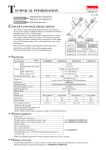
Engine Chain Saw 250mm
W
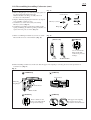
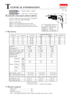
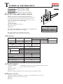
CONCEPT AND MAIN APPLICATIONS
Primarily targeted at professionals who frequently prune
fruit trees or street trees, these new models have been developed
as "the lightest-in-the world*" top handle engine chain saws.
(*Note: according to our investigation, in the category of engine
chain saw and at the date of August, 2004)
Other benefits are:
Inertia chain brake
Automatic adjustable chain oiling
Easy start system
Idling start
H
DCS230T and PS-220TH feature no load speed of 11,500rpm whilst
DCS231T and PS-221TH feature 10,500rpm.
L
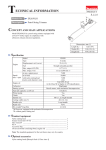
Dimensions: mm (")
Length (L)
242 (9-1/2)
Width (W)
215 (8-1/2)
Height (H)
202 (8)
DCS230T and DCS231T are Makita brand models.
PS-220TH and PS-221TH are Dolmar brand models.
Specification
Voltage (V)
Current (A)
Continuous Rating (W)
Input
Output
Cycle (Hz)
Max. Output (W)
740
Model
Specification
DCS230T
PS-220TH
Chain blade
Standard guide bar: mm (")
DCS231T
PS-221TH
250 (9-7/8)
Carving bar
Pitch (")
Gauge (")
1/4
0.050
Sprocket nose bar bar
Pitch (")
Gauge (")
3/8
0.050
No load speed: min-1=rpm
Displacement: ml
11,500
10,500
Max output: kw
22.2
0.74
Fuel tank capacity: l
0.2
Chain oil tank capacity: l
Power head weight: kg (lbs)
0.19
2.5 (5.5)
Standard equipment
Chain blade 250mm .......... 1 (25AP-60E for Carving bar or 91VG-40E for Sprocket nose bar)
Guide bar ........................... 1 (Carving bar or Sprocket nose bar)
Guide bar scabbard ............ 1
Wrench 13-16 .................... 1
Note: The standard equipment for the tool shown above may differ by country.
Optional
accessories
Chain blade 250mm (25AP-60E for carving bar or 91VG-40E for sprocket nose bar)
Guide bar (Carving bar or Sprocket nose bar)
Chain oil
Engine oil
2 / 20
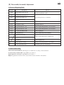
[II] Disassembly/Assembly/Adjustment
1. Necessary Repairing Tools
Tool No.
Description
Use for
Disassembling/assembling kickback brake
(inertia chain brake) system
1R003
Retaining Ring Pliers ST-2N
1R028
Bearing Setting Tool 20-12.2
1R034
Bearing Setting Plate 12.2
1R048
Drill Chuck Remover 11
1R091
Copper Round Bar 20-100
Removing Flywheel
1R127
Air Tightness Tester
Testing Carburetor
1R170
T-type Hex Wrench 3-127
Removing/installing M4 Hex socket head bolt
1R171
T-type Hex Wrench 4-130
Removing/installing M5 Hex socket head bolt
1R229
1/4" Hex Shank Bit for M5
Removing Engine
1R269
Bearing Extractor
Removing Bearing from Crankshaft
Press-fitting Bearing to Crankshaft
13mm Hex Socket Bit
Removing/installing Clutch and Flywheel
Impact Driver (6990D, 6916D or the like)
Iron Hammer
Removing Flywheel
0.3mm Thickness Gauge
Fixing and adjusting Ignition coil complete
0.7mm Spark Plug Gauge
Adjusting spark gap of Spark plug
2. Lubrication/Sealing
After you have disassembled the following parts, do lubrication or sealing as instructed below.
Needle bearing on clutch drum: Apply Makita grease N No. 2.
Spiral spring of recoil starter: Apply Makita grease N No. 2.
Engine: Apply Three bond 1215 to the contact surface between Crankcase and Cylinder.
3 / 20
3. Disassembly/Assembly
CAUTION: Be sure to remove gasoline and saw chain from the machine for safety before repair/ maintenance!
Refer to the instruction manual for detailed information on how to remove or adjust saw chain.
IMPORTANT: When replacing Oil pump, also replace chain oil by fresh one.
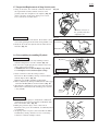
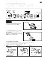
3-1. Clutch Section
DISASSEMBLY
1) Clutch can be easily removed using Impact driver without locking Spindle.
2) Do not remove Spark plug because Clutch is removed using compression resistance.
CAUTION: Be sure to turn off Engine stop switch to avoid injury from accidental engine startup.
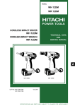
3) Attach 13mm hex socket bit to Impact driver. Clutch is left-handed. Therefore, remove Clutch by turning the hexagonal
portion in the center of Clutch clockwise with the Impact driver. (Fig. 1)
Fig. 1
ASSEMBLY
Fig. 2
Flat washer 8
1) Apply Makita grease N No. 2 to the Needle bearing on
Clutch drum, and insert Clutch drum in Crankshaft.
2) Set Flat washer 8 in place so that the chamfered side of
the washer faces the engine side. (Fig. 2)
3) Assemble Clutch to Crankshaft first by turning it
counterclockwise by hand, then turning counterclockwise
for one second with Impact driver. (Fig. 1)
loosen
tighten
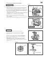
3-2. Inspection of Clutch Drum
Fig. 3
1) If the sprockets are dirty or worn down, clean them or
replace Clutch drum by new one. (Fig. 3)
2) At the same time, check the drive links of saw chain
for damage or wear. And if necessary, replace them
by new ones. (Fig. 4)
Fig. 4
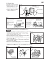
3-3. Oil Pump Section
DISASSEMBLY
1) Remove Worm gear by turning counterclockwise with thin screwdriver. (Fig. 5)
2) Unscrew 4x18 Tapping screw, and remove Oil pump cover and Chain slider (L).
3) Remove two M4x12 Pan head screws. While levering up Connector a little bit,
pull off Connector and Oil tube from Oil pump. Now Oil pump can removed. (Fig. 6)
Note: Be sure to replace Oil pump entirely by new one.
4) Check if Connector and Oil tube is cracked or clogged and if Spring (oil filter) is clogged. (Fig. 6)
Fig. 5
Fig. 6
Worm gear
Oil pump
Connector
Oil tube
Spring
4 / 20
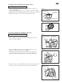
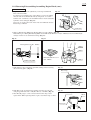
3-3. Oil Pump Section (cont.)
ASSEMBLY
1) Fasten two M4x12 Pan head screws, first A then B so that Worm gear does not touch Oil pump. (Fig. 7)
2) Do not forget to set Flat washer 10 in place. (Fig. 7)
3) Install Oil pump cover and Worm gear, first Oil pump cover, then Worm gear.
4) After installation of Worm gear, make sure that Worm gear can be turned easily by hand.
3-4. Adjusting the Flow of Chain Oil
The flow of chain oil can be adjusted by turning the adjusting screw on the bottom of the machine using the slotted
screwdriver portion of Wrench 13-16 supplied.
Turn clockwise to increase the flow, and counterclockwise to decrease. (Fig. 8)
Fig. 7
Fig. 8
Flat washer 10
Pan head screw
M4x12
Decrease
Increase
3-5. Ignition System
INSPECTION OF PLUG CAP
1) Remove Plug cap from Spark plug. Then using circuit tester, check the
electrical conduction between Plug cap spring and the ground (earth)
terminal of Ignition coil complete. If the value of electrical resistance
is about 7k ohms, the conduction is normal. (Fig. 9)
2) If there is no or unstable electrical resistance, check if Plug cap spring
is properly connected with the ignition cable of Ignition coil complete.
Lubricate the inside of Plug cap using aerosol spray lubricant, and then
pull the ignition cable and Plug cap together spring out of Plug cap
using pliers. (Fig. 10)
Fig. 9
Ignition coil
complete
Plug cap
Ground (earth)
terminal
3) Check if Plug cap spring is properly connected with the ignition cable.
If not, connect in the correct way as described below in 4).
Also check if Plug cap is cracked. If cracked, replace it by new one.
Fig. 10
4) Install Plug cap spring on the ignition cable of Ignition coil complete
by piercing the needle portion of the spring in the center of the cable.
While taking care not to let Plug cap spring fall off the cable, grab the
cable with pliers and pull the spring back into Plug cap. (Fig. 11)
Ignition cable
Aerosol spray
lubricant
5) Check if Plug cap spring is properly connected with the ignition cable
of Ignition coil complete using circuit tester as described above in 1).
Defective connection can cause weak or no spark at Spark plug.
Plug cap
Fig. 11
Pierce in the center
of ignition cable.
Plug cap spring
Plug cap
Pull with pliers.
5 / 20
3-5. Ignition System (cont.)
Fig. 12
INSPECTION OF SPARK PLUG
1) Remove Plug cap, and remove Spark plug with supplied Wrench 13-16.
Note: If Spark plug is wet with fuel, wipe it off with a clean cloth and
dry Spark plug with power blower.
2) Remove carbon deposits on the center electrode and the ground
electrode of Spark plug using wire brush.
3) Adjust the spark gap to 0.6-0.7mm by inserting a 0.7mm Spark plug
gauge in the spark gap. (Fig. 12)
4) Check if the spark occurs in the spark gap as described below:
Install Plug cap on Spark plug, touch the threaded portion of the plug
to the engine block, and then pull Recoil starter rope.
5) If no spark occurs, check the electrical conduction as described above
in 1) of CHECKING PLUG CAP.
And if the conduction is normal, replace Spark plug by new one and
re-check for a spark in the spark gap.
Center electrode
0.6 - 0.7mm
Ground electrode
Spark gap = the distance between the center
electrode and the ground electrode
3-6. Removal/Installation of Ignition Coil Complete
REMOVAL
1) Before removing Ignition coil complete, remove Starter case, pull Plug cap off from Spark plug and pull the ground
(earth) wire off from the terminal on Ignition coil complete. (Fig. 13)
2) Remove two M4x20 Hex socket head bolts. Now Ignition coil complete can be removed. (Fig. 14)
Note: Be careful not to lose two Spacers through which the Hex socket bolts are inserted.
Fig. 13
Fig. 14
Flywheel
Ground (earth) terminal
Ground (earth) wire
Spacer
(2pcs)
M4x20 Hex socket head bolt (2pcs)
INSTALLATION
1) Put Spacers and Ignition coil complete in place, and pretighten M4x20 Hex socket head bolts. Do not tighten the bolts
securely in this step. Insert a 0.3mm thickness gauge between Ignition coil complete and the magnet portion of Flywheel.
Ignition coil complete will stick to the magnet portion of Flywheel. Then tighten the bolts securely.
2) Remove the thickness gauge, then turn Flywheel to make sure that Ignition coil complete does not touch Flywheel.
3-7. Inspection/Replacement of Stop Switch
INSPECTION
1) Remove Top handle cover by removing four 4x18 Tapping screws.
2) Using circuit tester, check the electrical conduction between the terminals.
Stop switch is normal if the terminals are not conducted with the engine
turnded on and conducted with the engine turned off. (Fig. 10)
Fig. 15
Switch
6 / 20
3-7. Inspection/Replacement of Stop Switch (cont.)
3) Using circuit tester, also check the conduction between
the engine block and the terminal connector of the
ground (earth) wire of Ignition coil complete. (Fig. 16)
At the same time, check wrong wiring, loose screws,
loose connections or broken wires.
Fig. 16
Terminal connector of
the ground (earth) wire
of Ignition coil
REPLACEMENT
1) Disconnect lead wires from Switch. Now Switch can be
removed by pushing from the inside of Top handle cover.
2) Route the two lead wires (black and red) under the two
fuel tube. (Fig. 17)
Fig. 17
Lead wires
Fuel tubes
3-8. Disassembling/Assembling Flywheel
Fig. 18
DISASSEMBLING
1) Flywheel can be removed easily with Impact driver
without locking Piston as well as Clutch. (Fig. 18)
2) Do not remove Spark plug because Clutch is removed
using compression resistance.
CAUTION: Be sure to turn off Engine stop switch
to avoid injury from accidental engine startup.
Flywheel
Turn Hex nut M8
counterclockwise.
3) Attach 13mm hex socket bit to Impact driver.
Fig. 19
Then remove Hex nut M8 by turning counterclockwise
with the Impact driver. (Fig. 19)
Note: Be sure that Hex nut M8 is right-handed.
4) Remove Flywheel by hitting Crankshaft hard with Copper
round bar 20-100 (1R091) and iron hammer. (Fig. 19)
5) Two Ratchets on Flywheel can be removed by removing
M5x12 Hex socket button bolts with T-type hex wrench
3-127 (1R170).
1R091
ASSEMBLING
1) Install two Torsion spring 15 on Flywheel as illustrated
on Flywheel, then fasten two Ratchets to Flywheel with
Hex socket button bolts. (Fig. 20)
2) Fitting the protrusion (key) on the center hole of
Flywheel to the groove in Crankshaft, assemble Flywheel
to Crankshaft.
3) Set Spring washer 8 in place, then fasten Hex nut M8 to
Crankshaft by turning clockwise for one second using
13mm hex socket bit and Impact driver.
Fig. 20
7 / 20
3-9. Replacement of Recoil Starter Rope
Fig. 21
DISASSEMBLING
1) Remove Side handle, and separate Recoil starter assembly from
the machine.
2) If Recoil starter rope is connected with both Starter knob and Reel,
pull Starter knob to draw the rope out of Starter case and cut it.
If the rope cannot be cut, pull Starter knob to draw out the rope till
Reel rotates one turn. Then hook the rope on the U-shaped notch in
Reel as illustrated in Fig. 21, and turn Reel counterclockwise till
Spiral spring is unwound enough.
CATION: Reel rotates very fast if you release Recoil starter rope
being pulled. Be very careful not to cut your hands.
3) Unscrew Set screw, and remove Cam and Torsion spring.
4) Remove Reel while pushing Spring case so that it does not get out
of place. (Fig. 22)
5) Untie the knots at Starter knob and Reel, then remove worn rope.
Recoil starter rope
U-shaped notch
Reel
Fig. 22
Spring case
Push Spring case.
Reel
Fig. 23
ASSEMBLING
1) If Spiral spring has been removed, first put it in place.
2) Put new Recoil starter rope through Starter case. (Fig. 23)
Note: When using a commercial rope, cut it to 750mm.
3) Tie knots at Reel and Starter knob as illustrated in Fig. 24, 25.
Do not forget to install Rope stopper as illustrated in Fig. 25
before tying a knot at Starter knob.
Important: Rope stopper is not reversible when assembled to
Starter knob. Be sure to put it through Recoil starter rope as
illustrated in Fig. 25. Failure to follow this instruction can result
in broken rope.
Fig. 24
Fig. 25
Reel
Rope stopper
Starter knob
8 / 20
3-9. Replacement of Recoil Starter Rope (cont.)
4) Connect Reel with Spiral spring by Fig. 26
turning clockwise while tilting it
[Start of connecting]
as illustrated in Fig. 26.
Take care not to Tilt down Reel so that this portion
By rotating Reel clockwise about
hook this portion can be hooked on Spiral spring.
half a turn, Reel will move down
on Spiral spring.
to touch Spring case completely,
indicating that it has been correctly
connected with Spiral spring.
Remember the point at which Reel
moved down.
CATION: No force is required to
Lift up this portion
connect Reel with Spiral spring.
Spiral spring
so that it cannot
Take care not to deform Spiral
touch Spiral spring.
spring by forcing Reel against
Spiral spring.
[Correctly connected]
Put in place without being
caught by Spiral spring
Hooked on
Spiral spring
5) Put Torsion spring and Cam in place, and fasten them securely
with Set screw. (Fig. 27)
Important: Reel is not correctly connected with Spiral spring
if it does not turn smoothly after secure tightening of Set screw.
Reassemble Reel to Spiral spring as described above in 4).
Fig. 27
6) Turn Reel counterclockwise to wind up Recoil starter rope.
(Fig. 28)
Fig. 28
Torsion spring
7) The loose portion can be eliminated from the rope by hooking
Fig. 29
the rope on the U-shaped notch in Reel, turning Reel clockwise
two times, then removing the rope from the U-shaped notch.
(Fig. 29)
Remark: There are two points at which Reel hooks on Spiral spring.
Therefore, turn Reel so that it moves down to touch Spring case
at the same position as it did at first in 4).
Cam
9 / 20
3-9. Replacement of Recoil Starter Rope (cont.)
If Spiral Spring Gets Out of Spring Case
1) Fix the straight end of Spiral spring in the small hole on Spring case
as illustrated in Fig. 30.
Then set Spiral spring in Spring case by winding up clockwise. (Fig. 31)
2) Spiral spring is factory-lubricated with red grease. However, you may use
Makita grease N No. 2 when repairing. Apply a little amount.
Fig. 30
Spiral spring
small hole
Spring case
Fig. 31
3-10. Disassembling/Assembling Carburetor
REMOVING FROM ENGINE BLOCK
1) Remove Cleaner case cover.
2) Remove Choke lever by unscrewing PT3x10 Tapping screw using
slotted screwdriver. (Fig. 32)
Fig. 32
slotted screwdriver
3) Remove two M5x45 Pan head screws that fasten Cleaner case and
Carburetor. Then remove Cleaner case. (Fig. 33)
Note: If the pan head screws are left on Cleaner case, Cleaner case
cannot be removed. Be sure to remove the pan head screws from
Cleaner case before separating Cleaner case from the engine block.
Fig. 33
4) Remove two tubes, then while tilting Carburetor so that it does not touch
Throttle wire, separate Carburetor from the engine block. (Fig. 34)
Fig. 34
Choke lever
M5x45 Pan head screw
Throttle wire
Carburetor
10/ 20
3-10. Disassembling/Assembling Carburetor (cont.)
DISASSEMBLING & CLEANING
1) Remove Diaphragm cover and Diaphragm gasket set
by unscrewing four Pan head screws.
Note: If Gasket is sticking, carefully remove it
because it is easily broken.
2) Replace Metering diaphragm if it shows any sign of
wear, wrinkles, curling or tears.
3) Controller set can be removed by unscrewing
M3x4 (+) Screw. (Fig. 35)
4) Controller set includes Control lever, Inlet needle,
Spring and Hinge pin. When repairing Controller set,
replace the four parts at a time. (Fig. 35)
5) Before assembling Controller set, be sure to check
Inlet needle for wear or deformation. (Fig. 36)
Fig. 35
Control lever
Spring
M3x4 (+) Screw
Inlet needle
Hinge pin
Fig. 36
[WRONG]
[Inlet needle]
Use of worn-down
Inlet needle will
result in air pressure
leakage.
GOOD
WORN DOWN
6) When installing Control lever, make sure that the upper end of Spring is correctly placed over the protrusion of
Control lever. (Fig. 37)
Fig. 37
[CORRECT]
[WRONG]
Control lever
Metering
diaphragm
Control lever
Inlet needle
[WRONG]
Dust or debris on the
valve seat will result in
air pressure leakage.
[WRONG]
The upper end of Spring
is not placed over the
protrusion of Control lever.
11/ 20
3-10. Disassembling/Assembling Carburetor (cont.)
7) Before removing two Pan head screws, tighten the idling screw on (A) to the full. (Fig. 38)
8) Before installing Strainer, ensure that it is not clogged with dust, dirt or debris. (Fig. 38)
9) Clean up the drainages in Carburetor first by spraying commercial carburetor cleaner and then, several minutes after,
by washing with gasoline.
Fig. 38
[Exploded View of Carburetor]
Throttle holder
Controller set
O ring 15
Pan head screw
(4pcs)
Pan head screw
(2pcs)
(A)
Gasket
Gasket
Pump
diaphragm
Metering
Diaphragm
diaphragm cover
Strainer
Fig. 39
ASSEMBLING
1) Referring to Fig. 38, assemble Carburetor.
2) Install (A) so that the choke adjuster is placed on
the opposite side to the tube ports. (Fig. 39)
Choke adjuster
Tube ports
3-11. Testing Air Tightness of Carburetor
Connect Air tightness tester (No.1R127) to the nipple
(the fuel suction port), and increase the pressure of the
tester up to 0.05Mpa.
Air tightness is normal if the tester keeps on indicating
0.05Mpa about ten seconds. (Fig. 40)
Fig. 40
Air tightness tester
(1R127)
3-12. Assembling Parts in Handle
1) Hook the longer leg of Torsion spring 11 in the three protrusions on Lock-off lever. (Fig. 41)
2) Hook the other end of Torsion spring 11 on Throttle lever. (Fig. 42)
3) Insert Rod into Throttle lever as illustrated in Fig. 43.
Fig. 41
Fig. 42
Lock-off lever
Torsion spring 11
Torsion spring 11
Throttle lever
Fig. 43
Rod
Throttle lever
12/ 20
3-13. Routing Tubes
1) Route Tubes as illustrated in Fig. 44. Fig. 44
2) Install Gasoline filter on the end of
the fuel suction tube, which will be
Primer
placed in the fuel tank.
pump
Connect Tube 3-140 with the fuel
suction tube using Tube joint. (Fig. 44)
3) On the top of Housing, route Tubes
as illustrated in Fig. 45, 46.
Tube 3-140
Tube joint
Fuel suction tube
Gasoline filter
Top handle
Fig. 45
Fig. 46
[Around the fuel tank]
Place the two tubes
parallel to one another.
Ensure that the fuel
suction tube is placed
inside.
Then insert the tubes
into the fuel tank.
[On the top of Housing]
Fuel suction tube
Be sure to place the
fuel suction tube
inside so that it does
not touch the hex
socket head bolt
which will be very
hot from the heat
of the engine.
Fuel suction tube
3-14. Removing/Disassembling/Assembling Engine Block
REMOVAL
1) Proceed to disassemble the machine until the following parts are removed; Fig. 47
Spark plug, Clutch complete, two M4x12 Pan head screws (used for
1R170
fastening Oil pump), Exhaust muffler complete, Starter case complete,
Ignition coil complete, Flywheel, Carburetor
2) Insert T-type Hex Wrench 3-127 (No. 1R170) from the through hole near
the hole for the Carburetor fastening screw. And then loosen two M4x14
Hex socket head bolts that fasten Insulator. (Fig. 47)
3) Remove Damper spring and 4x18 Tapping screw that fastens Top handle to
Housing complete. (Fig. 48)
4) Release Top handle from Housing by pulling Air duct from the Ignition
coil installation side. (Fig. 49)
5) Raise the rear end of Top handle by pivoting on the front end, and remove
two M4x14 Hex socket head bolts that fasten Insulator.
Be careful not to lose the two bolts. (Fig. 50)
6) Using Impact driver and 1R229 (or 1R171), remove four M5x20 Hex socket head bolts from the top and the bottom of
the Engine block. Now Engine block can be removed from the left side of Housing.
Fig. 48
Fig. 49
Fig. 50
Air duct
Damper spring
13/ 20
3-14. Removing/Disassembling/Assembling Engine Block (cont.)
DISASSEMBLING
Fig. 51
1) Separate Crank case from Cylinder by removing four M5x20
Hex socket head bolts.
If cannot be separated because of the adhesive, remove by hitting
the both ends of Crankshaft alternately with plastic or wooden
hammer. Be careful not to let Crankshaft tilt too much at this time.
Cylinder can be damaged. (Fig. 51)
Now you can replace Oil seals on the ends of Crankshaft and two
Piston rings on Piston.
Crankshaft
2) Remove Ball bearing 6001 using Bearing Extractor (No. 1R269). (Fig. 52)
Note: When press-fitting Ball bearing 6001, insert Drill Chuck Remover 11 (No. 1R048) between Crankshaft (R)
and (L) in order not to deform the bearing. (Fig. 53)
Fig. 52
Fig. 53
Bearing Extractor (No. 1R269)
1R028
1R048
Drill Chuck Remover 11
(No. 1R048)
1R034
Ball bearing 6001
3) Pull off Piston clip from Piston pin while turning in the loosening
direction using pliers. (Fig. 54)
Fig. 53
Piston clip
4) Push Piston pin out of Piston by pushing from the opposite side
using T-type Hex Wrench 4-130 (No. 1R171) or the like. (Fig. 55)
5) Now Needle gauge 8 can be extracted from Connecting rod for
replacement. When replacing Piston, replace two Piston clip at a time.
Fig. 55
Piston clip
1R171
Piston pin
14/ 20
3-14. Removing/Disassembling/Assembling Engine Block (cont.)
ASSEMBLING
1) Assemble Piston so that the triangular marking on Fig. 56
its top is placed on the exhaust muffler installation
side (the longer Crankshaft side). (Fig. 56)
triangular marking
Crankshaft, longer
2) Piston ring is not reversible when assembled
to Piston. Adjusting the end-gap of Piston ring
fit in the groove of Piston; first the lower Piston
ring, then the upper one. (Fig. 57)
Caution:
1) Because Piston ring is easily broken, take care
not to expand excessively when installing new
one.
2) When inserting Piston into Cylinder, be very
careful with the position of the end-gap of
Piston ring, never placing Piston ring over the
knock pin. It will result in broken Piston ring
to force Piston into Cylinder with the ring
placed over the knock pin.
Fig. 57
[WRONG]
[CORRECT]
Piston ring
Knock pin
[WRONG]
3) Crankshaft is not reversible when assembled to
Fig. 58
Cylinder. Place it so that the longer shaft faces
the Exhaust muffler installation side. (Fig. 58)
matching surface
4) Apply "Three bond 1215" to the matching surface
to apply "Three
between Crankcase and Cylinder; it is enough to
bond 1215"
apply the adhesive only to the shaded portion of
Crankcase.
And then aligning the protrusion on Crankcase
with one on Cylinder as illustrated in Fig. 59,
assemble them together.
Crankshaft, longer
Exhaust muffler
installation side
Cylinder
Crankcase
Fig. 59
Crankcase
Cylinder
Align these two protrusions.
15/ 20
3-15. Disassembling/Assembling Kickback Brake System
DISASSEMBLING
Fig. 60
Fig. 61
Chain slider (R)
1) Release Brake band (Hand guard cover) by
pulling Front hand guard as illustrated in Fig. 60.
2) If Sprocket cover is assembled to the machine,
separate by loosening Collared hex nut M8 with
supplied Wrench 13-16.
Front
hand guard
3) Remove Spring cover and Chain slider (R) from
Sprocket cover Fig. 61.
4) Grasp the rear end of Compression spring 9
Fig. 62
with Retaining ring pliers ST-2N (No. 1R003),
and pull it off from Link plate complete.
(Fig. 62)
Note: Use Retaining ring pliers ST-2N
(No. 1R003) when grasping or tightening parts
in the following disassembling/assembling steps.
Link plate
5) Remove Compression spring 6.
complete
6) Grasp the Front hand guard section together
Fig. 63
with Compression spring 9, and pull them off
from the machine. (Fig. 63)
7) When removing Brake band (Hand guard cover),
unscrew two 4x12 Tapping screws.
1R003
Compression
spring 9
Link plate complete
Front guard
section
ASSEMBLING
Fig. 64
1) Set all parts except Compression spring 9 in place of
Sprocket cover by doing the reverse of the assembling steps.
2) Grasp the rear end of Compression spring 9 with Retaining
ring pliers ST-2N (No. 1R003), and then it put through
Link plate complete while levering up Link plate complete
as illustrated in Fig. 64.
3) Put Compression spring 9 in Sprocket cover as follows;
First, compress one end of the spring with one jaw of the
pliers put in the first through hole in Link plate complete
other put around the fourth winding of the spring.
Then push down the other end of the spring. (Fig. 65)
4) Install Spring cover, and fasten Brake band (Hand guard
cover) with 4x12 Tapping screws.
Then move Front hand guard to make sure that it works
properly.
Fig. 65
Compress this end.
Push down
this end.
16/ 20
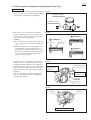
3-16. Miscellaneous Remarks
[1] Do not reuse Gaskets between Exhaust muffler and Cylinder.
Always use new one for replacement. (Fig. 66)
Fig. 66
[2] If any sawdust or debris in the saw chain tensioner in Sprocket cover,
blow it out using power blower or the like. (Fig. 67)
Fig. 67
4. Adjustment
See Instruction manual for adjustment of idling settings and saw chain tension.
P 17/ 20
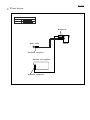
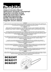
Circuit
diagram
Color index of lead wires' sheath
Black
Red
Receptacle
Body earth
Insulated connector
Ignition coil complete
Insulated receptacle
Switch
P 18/ 20
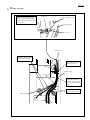
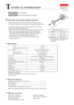
Wiring
diagram
Connect the lead wires (red, black)
with the terminals of switch before
assembling the switch to the top
handle cover.
Switch
Receptacle
Top handle cover
Lead wire (red)
Lead wire (black)
Assemble the switch to the top handle cover
so that the rib on the top handle cover is
positioned between the terminals of the switch.
Switch
Top handle cover
Fix the lead wires with
this lead wire holder.
Rib
P 19/ 20
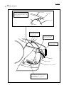
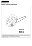
Wiring
diagram
Route the lead wires through
the space (the shaded portion)
between the main housing and
the top cover.
Lead wires
Top handle cover
Main housing
Top cover
Lead wires
Fix the lead wires with
the lead wire holders.
Route the lead wires
under the tubes.
Tubes
Inside wall
Pins
Route the lead wires
and the tubes between
the pins and the inside
wall.
Fix the tubes with
the lead wire holders.
Body earth
P 20/ 20
Wiring
diagram
Route the lead wire through
the space (the shaded portion)
between the main housing and
the baffle plate.
Main housing
Lead wire
Baffle plate
Route the lead wire
between the pin and
the inside wall.
Inside wall
Pin
Fix the lead wire with
the lead wire holder.
Route the lead wire
under the tubes.
Tube
Lead wire
Ignition coil complete
Assemble the insulated receptacle
to the ignition coil complete as
illustrated here.