1
EN CONDENSING TANKLESS GAS WATER HEATER
SP CALENTADOR A GAS TIPO CONDENSADO
SBB800R
Rev. 11/12
Use and Care Manual
Manual de uso y mantenimiento
5995615118 November 2012
*SBB800R*
CONDENSING TANKLESS GAS WATER HEATER
Use and Care Manual
Models : EN19WI30LS
EP19WI30LS
EN18WI30LS
EP18WI30LS
FOR USE IN RESIDENTIAL APPLICATIONS IN THE UNITED STATES ONLY. NOT INTENDED FOR USE IN CANADA OR MEXICO.
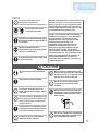
WARNING
If the information in this manual is not followed exactly, a fire or explosion
may result causing property damage, personal injury, or death.
- Do not store or use gasoline or other flammable vapors and liquids in the
vicinity of this or any other appliance.
- WHAT TO DO IF YOU SMELL GAS
t%POPUUSZUPMJHIUBOZBQQMJBODF
t%POPUUPVDIBOZFMFDUSJDBMTXJUDIEPOPUVTFBOZQIPOFJOZPVSCVJMEJOH
t*NNFEJBUFMZDBMMZPVSHBTTVQQMJFSGSPNBOFJHICPSTQIPOF'PMMPXUIF
HBTTVQQMJFSTJOTUSVDUJPOT
t*GZPVDBOOPUSFBDIZPVSHBTTVQQMJFSDBMMUIFmSFEFQBSUNFOU
*OTUBMMBUJPOBOETFSWJDFNVTUCFQFSGPSNFECZBRVBMJmFEJOTUBMMFSTFSWJDF
agency or the gas supplier.
Low NOx Approved
by SCAQMD
14 ng/J or 20 ppm
(Natural Gas Only)
Thank you for purchasing this Electrolux Tankless Gas Water Heater.
Before using, please:
Read this manual completely for operation instructions.
Completely fill out the product registration/warranty card (included
separately) and mail the detachable portion to Electrolux Home
Products, lnc.
Registration can also be done online or over the phone.
See registration card for details.
Keep this manual where it can be found whenever necessary.
Installation must conform with local codes, or in the absence of local
codes, the National Fuel Gas Code, ANSI Z223.1/NFPA 54.
Electrolux Home Products, Inc. reserves the right to discontinue, or
change at any time, the designs and/or specifications of its products
without notice.
Electrolux Home Products, Inc.
www.electroluxappliances.com
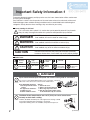
Important Safety Information-1
To prevent damage to property and injury to the user, the icons shown below will be used to warn
of varying levels of danger.
Every indication is critical to the safe operation of the water heater and must be understood and observed.
Potential dangers from accidents during installation and use are divided into the following four
categories. Closely observe these warnings; they are critical to your safety.
Icons warning of risk level
This is the safety alert symbol. It is used to alert you to potential personal injury hazards.
Obey all safety messages that follow this symbol to avoid possible injury or death.
DANGER
DANGER indicates an imminently hazardous situation which,
if not avoided, will result in death or serious injury.
WARNING
WARNING indicates a potentially hazardous situation which,
if not avoided, could result in death or serious injury.
CAUTION
CAUTION indicates a potentially hazardous situation which,
if not avoided, may result in minor or moderate injury.
CAUTION
CAUTION used without the safety alert symbol indicates a potentially
hazardous situation which, if not avoided, may result in property damage.
Other icons
Electric
Shock.
High
Temperature.
Be sure
to do.
Prohibited
No flame.
Don’t
touch.
Ground.
Don’t
disassemble
the equipment.
Don’t touch
with a wet
hand.
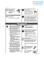
DANGER
7BQPSTGSPNnBNNBCMFMJRVJETXJMMFYQMPEFBOEDBUDImSFDBVTJOHEFBUIPSTFWFSFCVSOT
Prohibited
Do not use or store flammable products such as gasoline, solvents or
adhesives in the same room or area near the water heater.
Keep flammable products: Vapors:
1. Far away from the water 1. Cannot be seen.
2. Vapors are heavier than air.
heater.
3. Go a long way on the floor.
2. In approved containers.
4. Can be carried from other rooms
3. Tightly closed.
to the main burner by air currents.
0VUPGDIJMESFOTSFBDI
Hot Water Heater temperatures over 125°F (52°C) can cause severe burns
instantly or death from scalding.
Prohibited
2
Children, disabled and elderly are at the highest risk of being scalded.
Feel water temperature before bathing or showering.
Temperature limiting valves are available, ask professional person.
(Continued)
(Continued)
Prohibited
[When supplying combustion air
Air supply vent
from the indoors]
Do not use the water
heater if the intake/
exhaust pipe is
displaced, has holes,
is clogged or is
corroded.
Be sure
to do.
Check whether or not the air
supply vent is blocked with
dust, trash, a towel, or the like.
Towel
Blocking the opening may result
in incomplete combustion.
Prohibited
Do not allow anyone to change the
water temperature while hot water
is being used.
To prevent scalding, do not change the
water temperature to a higher setting.
Be sure
to do.
After the water heater has been out of
use for a long time make sure that you
mMMUIFDPOEFOTBUFUSBQXJUIXBUFS
This is to prevent dangerous exhaust
gases from entering the building.
'BJMVSFUPmMMUIFDPOEFOTBUFUSBQDPVME
result in severe personal injury or death.
(Refer to page 20 for further instructions.)
WARNING
No flame.
A. This water heater does not have
a pilot. It is equipped with an
ignition device that automatically
lights the burner. Do not try to
light the burner by hand.
B. BEFORE OPERATING smell all
around the water heater area for
evidence of leaking gas. Be sure
to smell next to the floor because
some gas is heavier than air and
will settle on the floor.
WHAT TO DO IF YOU SMELL GAS.
t%POPUUSZUPMJHIUBOZ
appliance.
t%POPUUPVDIBOZFMFDUSJDBM
TXJUDIEPOPUVTFBOZQIPOFJO
your building.
tImmediately call your gas
TVQQMJFSGSPNBOFJHICPST
QIPOF'PMMPXUIFHBTTVQQMJFST
instructions.
tIf you cannot reach your gas
TVQQMJFSDBMMUIFmSFEFQBSUNFOU
C. Use only your hand to turn
the gas valve knob. Never use
tools. If the knob will not turn by
IBOEEPOUUSZUPSFQBJSJU$BMM
BRVBMJmFETFSWJDFUFDIOJDJBO
Force or attempted repair may
SFTVMUJOBmSFPSFYQMPTJPO
D. Do not use this water heater if
any part has been under water.
MNNFEJBUFMZDBMMBRVBMJmFE
service technician to inspect the
water heater and to replace any
damaged parts.
Be sure
to do.
Be sure
to do.
When a gas leak is noticed:
1. Stop use immediately
2. Close the gas valve
3. Open windows and doors
If you detect abnormal combustion
or abnormal odors, or during an
FBSUIRVBLFUPSOBEPPSmSF
1. Turn off the hot water supply
2. Turn off the power to the water
heater
3. Turn off gas and water supply
valve
4. Call the nearest Electrolux agent
&YQMPTJPO)B[BSE
Prohibited
If the temperature and pressure relief
valve is dripping or leaking, have a
RVBMJmFETFSWJDFUFDIOJDJBOSFQMBDFJU
Do not plug or remove the valve.
Failure to follow these instructions can result
in fire or explosion, and personal injury or
death.
High
Temperature.
Check the temperature
of the running hot water
before entering the
shower.
Check the temperature
before stepping into
the bath tub.
(Continued)
3
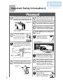
Important Safety Information-2
(Continued)
WARNING
Prohibited
Do not place the exhaust vent terminal
in an indoor environment by means
of adding walls and ceiling (Do not
enclose using corrugated sheets, etc.)
Prohibited
Carbon Monoxide Poisoning Hazard. Do
not install this water heater in a mobile
home, recreation vehicle or on a boat.
Prohibited
Do not use combustible chemicals such
as oil, gasoline, benzene etc. in the near
the heater or the exhaust vent terminal.
Prohibited
Do not store or use gasoline or other
flammable vapors and liquids in the
vicinity of this or any other appliance.
Prohibited
Do not place or use a spray can near
the water heater or the exhaust vent
terminal.
Exhaust vent
terminal
Carbon monoxide poisoning or fire may
occur as a result.
Do not place outdoors
Prohibited
Rain may enter the unit
or the burner fire may be
blown by the wind, causing
malfunction or fire as a result.
Outdoor
Be sure
to do.
Be sure the gas/power
supplied matches the
gas on the rating plate.
Ex. For EN19WI30LS
Be sure
to do.
Leave the proper clearance between
the water heater and nearby objects
(trees, timber, boxes with flammable
materials etc.).
Upper:
Min. 12" (300mm)
Left side:
Min. 2" (50mm)
Sug.3" (75mm)
from vent pipe*
Right side:
Min. 2" (50mm)
Front:
Sug. 24" (600mm)*
* Indicates suggested clearances for maintenance.
Prohibited
Do not place combustibles such as
laundry, newspapers, oils etc. near the
heater or the exhaust vent terminal.
Be sure
to do.
Prohibited
Exhaust vent
terminal
Prohibited
Be sure
to do.
4
Installation and service must be
QFSGPSNFECZBRVBMJmFEJOTUBMMFS
service agency or the gas supplier.
If this unit will be installed in a beauty
salon or other location where hair
spray or aerosols will be used, locate
the unit in a separate area that is
supplied with fresh air from outdoors.
Do not use hair spray or spray
detergent in the vicinity of the
heater.
[When supplying combustion air
from the indoors]
Check the air supply opening
for dust or obstructions.
Clogged
air supply
opening!!
(Continued)
(Continued)
Prohibited
Do not allow small children to play
unsupervised in the bathroom.
Do not allow small children to bath unsupervised.
Do not touch the power
cord with wet hands.
Don’t touch
with a wet
hand.
Be sure
to do.
Don’t
disassemble
the equipment.
Electric
Shock.
Consult the nearest Electrolux agent
if the water heater location needs to
be changed.
$POUBDUBRVBMJmFETFSWJDF
technician for any necessary repairs,
service or maintenance.
Contact Electrolux before using with
a solar pre-heater.
California Proposition 65 lists chemical substances
known to the state to cause cancer, birth defects,
death, serious illness or other reproductive harm.
This product may contain such substances,
be their origin from fuel combustion (gas, oil)
or components of the product itself.
The gas conversion kit shall be installed by a
RVBMJmFETFSWJDFBHFODZJOBDDPSEBODFXJUI
UIFNBOVGBDUVSFSTJOTUSVDUJPOTBOEBMM
applicable codes and requirements of the
authority having jurisdiction. The
information in the instructions must be
GPMMPXFEUPNJOJNJ[FUIFSJTLPGmSFPS
explosion or to prevent property damage,
QFSTPOBMJOKVSZPSEFBUI5IFRVBMJmFE
service agency is responsible for the proper
installation of this kit. The installation is not
proper and complete until the operation of
the converted appliance is checked as
TQFDJmFEJOUIFNBOVGBDUVSFSTJOTUSVDUJPOT
supplied with the kit.
Be sure
to do.
CAUTION
Be sure to electrically ground the
unit.
Prohibited
Ground.
Do not cover the water heater and
the exhaust vent terminal, store trash
or debris near it, or in any way block
the flow of fresh air to the unit.
Keep power cord free of dust.
Be sure
to do.
Prohibited
Prohibited
Prohibited
Be sure
to do.
Do not use the water heater for
other than hot water supply, shower
and bath.
%POPUVTFBCSPLFOPSNPEJmFEQPXFSDPSE
Do not bind, bend or stretch power cords.
Do not scratch, modify, or subject them
to impact or force.
Do not touch the exhaust vent pipe
and exhaust vent terminal during or
immediately after operation of the
water heater.
To prevent burns or scalding, turn off the
power button and wait until the equipment
cools before performing maintenance.
Do not turn off the water heater
while someone is bathing.
Prohibited
Don’t
touch.
Do not install in locations where
excessive dust or debris will be
in the air.
Prohibited
Do not use condensate, discharged
from the drain pipe, for drinking or
for consumption by animals.
5
Important Safety Information-3
CAUTION
Do not drink water that has been inside the
unit for an extended period of time. Do not
ESJOLUIFmSTUVTFPGIPUXBUFSGSPNUIF
unit in the morning.
This unit is only approved for installation
up to 4500 ft. (1350m) above sea level.
For installations at higher elevations, contact
Electrolux Home Products, Inc. for Instructions.
$MFBOUIFmMUFSPOUIFXBUFSJOMFUBT
frequently as required by the quality of
your local water.
Do not disassemble the remote controller.
Keep the area around the unit clean.
This may cause deformation.
If boxes, weeds, cobwebs, cockroaches etc. are in
the vicinity of the unit, damage or fire can result.
Do not get the remote controller wet.
Do not install the equipment where the
exhaust will blow on walls or windows.
If the water supply is in excess of 12 grains
per gallon (200 mg/L) of hardness, acidic
or otherwise impure, treat the water with
approved methods in order to ensure full
warranty coverage.
Do not use benzene, oil or fat detergents
to clean the remote controller.
Although it is water resistant, too much water can
cause damage.
Do not splash water on the remote
controller. Do not expose the remote
controller to steam.
Do not locate the remote controller near stoves or
ovens, this may cause damage or failure.
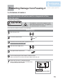
Preventing damage from freezing (
Problems resulting from scale formation
are not covered by the warranty.
Check ignition during use and extinction
after use.
Do not run water through the unit when
unit is not on.
When discharging hot water, make sure the unit is ON.
If water is run through the unit with the unit
OFF, water may condense inside the unit and cause
incomplete combustion or damage to the internal
electrical components.
For single-handle fixtures or valves, discharge
water setting the handle completely
to the water side.
6
p.18)
Damage can occur from frozen water within the
device and pipes even in warm environments.
Be sure to read below for appropriate measures.
Repairs for damage caused by freezing are not
covered by the warranty.
Take necessary measures to prevent
freezing of water and leakage of gas when
leaving the unit unused for long periods of
time. ( p.19, 20)
If it is snowing, check the exhaust vent
terminal for blockage.
%POPUVTFQBSUTPUIFSUIBOUIPTFTQFDJmFE
for this equipment.
Contents
Important Safety Information ....................................................................... 2
Contents ........................................................................................................ 7
Overview of Condensing Tankless Gas Water Heater .............................. 8
General Parts
Main Unit .................................................................................................... 9
Remote Controller.................................................................................... 10
Initial Operation ............................................................................................ 11
How to Use
Setting and Using the Water Heater ........................................................ 12
Flow Meter Alarm ...................................................................................... 14
Muting the Remote Controller ................................................................. 16
Adjusting the Maximum Output Temperature ........................................ 17
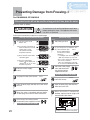
Preventing Damage from Freezing ............................................................. 18
Regular Maintenance................................................................................... 22
Troubleshooting ........................................................................................... 24
Follow-up Service ........................................................................................ 29
4QFDJmDBUJPOT ............................................................................................... 31
Limited Warranty .......................................................................................... 33
7
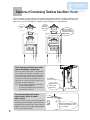
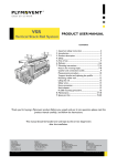
Overview of Condensing Tankless Gas Water Heater
This water heater is a high efficiency, fully condensing appliance. Unlike a traditional tankless water
heater, a condensing type captures heat from the exhaust gas and uses it to preheat the incoming
cold water as it passes through the secondary heat exchanger as illustrated below.
Conventional
type
Condensing
Tankless Gas
Water Heater
Exhaust
About
400˚F (200˚C)
Exhaust
About
120˚F (49˚C)
Water is heated
using the exhaust
gas which is about
400˚F (200˚C).
Secondary heat exchanger
Combustion gas
About
400˚F (200˚C)
Combustion gas
About
400˚F (200˚C)
Primary heat exchanger
Primary heat exchanger
condensate trap
Condensate
Hot water
Gas
Cold water
Hot water
Gas
Cold water
The condensing tankless gas water
heater discharges condensate.
When heat from the exhaust gas is collected within
the secondary heat exchanger, condensation occurs
from moisture in the exhaust gas and the resulting
water is discharged from the drain pipe (approx.
2 gallons/hour (7.5 liters/hour) maximum). It is not a
water leak. Do not plug or block the drain line as it
must always be allowed to freely flow.
Note : The condensate discharged is acidic with a
pH level of approximately 2-3.
A condensate neutralizer may be required by
local code prior to disposal.
Drain pipe
(Installation example)
Condensate
comes out
from here.
(Ex. EN18WI30LS)
The condensing tankless gas
water heater tends to show
white steam.
After the exhaust gas passes through the
secondary heat exchanger, it becomes low in
temperature and moisture rich which tends to
produce steam at the vent discharge terminal.
This is a normal occurrence.
8
During combustion, white
steam may often be seen.
This is normal.
General Parts -1
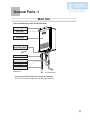
Main Unit
Indoor Wall Mounted, Power Vent/Sealed Model
Intake Pipe
Flue Collar
Front Cover
Water Drain Valve
(with Water Filter)
(Inside Water Inlet)
( p.22)
Pressure Relief Valve
Water Supply Valve
Gas Supply Valve
Drain Pipe
Discharges the
condensate.
(Ex. EN18WI30LS)
* The above illustration shows an example of installation.
The exact installation configuration may be slightly different.
9
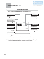
General Parts -2
Remote Controller
What is actually displayed depends on how the water heater is set.
Burner On Indicator
Setting Buttons
When burning, the
indicator is lit.
( p.13 and 15)
For setting the hot
water temperature,
the flow meter alarm,
and other settings.
Priority Indicator
When this indicator is lit,
the hot water temperature
can be set.
( p.12)
Temperature Setting
(Ex.:110°F)
Power On/Off Button
For turning the
heater on and off.
Flow Meter Setting
The display will flash
after hitting the flow
meter alarm set button.
( p.15)
Flow Meter Alarm Set Button
For setting the flow
meter alarm.
( p.14 - 15)
Error Code
A number will flash if
a failure occurs.
( p.28)
* Before use, remove the protective sheet from the remote controller surface.
Note: As shipped from the factory, the remote controller is set to display in °F and gallons.
To adjust the display to °C and liters, refer to the Installation Manual.
10
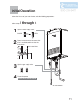
Initial Operation
Before the first use of your water heater, make the following preparations.
Follow steps
1
2
1 through 4.
Open the water supply valve.
OPEN
CLOSED
Open a hot water fixture to confirm that
water is available, and then close the
fixture again.
Hot water fixture
3
Open the gas supply valve.
4
Turn on the power.
Do not touch with wet hands.
(Ex. EN18WI30LS)
11
How to Use
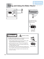
Setting and Using the Water Heater
2
1
(Starting with the Power Off)
1
Press the Power
On/Off Button.
On
The temperature will be
displayed on the remote
control thermostat.
On
Previous set
temperature
(Ex.: 110°F)
DANGER
To prevent scalding:
High Temperature
Hot Water Heater temperatures over 125°F (52°C) can cause
severe burns instantly or death from scalding.
r Children, disabled and elderly are at the highest risk of being scalded.
Feel water temperature before bathing or showering.
Temperature limiting valves are available, ask professional person.
Remote controller Display
r 8IFOTFUUJOHUIFVOJUUP'$'
PSIJHIFSUIF
temperature display will flash for 10 seconds and emit a tone
as a high temperature warning.
r Take caution when using the unit again after setting to 125°F
(52°C) or higher. Always check the set temperature before use.
r %POPUBMMPXBOZPOFUPDIBOHFUIFXBUFSUFNQFSBUVSFXIJMF
hot water is running.
12
Flashes for 10 sec
2(
Set temperature.
Always check the
temperature setting
before use.
)
3
4
Turn on hot
water.
Turn off the hot
water.
Hot
Cold
Check the indicator lights.
On
Off
Water temperature
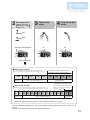
When using °F mode:
temperature settings below are examples. The temperature setting
°F: The
necessary depends on the usage, the length of piping and the time of year.
(
100
Washing
dishes, etc.
105
110
115
The maximum output temperature can be
set using the remote controller. ( p.17)
)
120
125
Shower, hot water supply, etc.
130
135
140
High temperature
*Initial factory setting is 110°F
When using °C mode:
temperature settings below are examples. The temperature setting
°C (°F): The
necessary depends on the usage, the length of piping and the time of year.
(
The maximum output temperature
can be set using the remote
controller. ( p.17)
)
37 38
(99) (100)
39 40 41 42 43 44 45 46 47 48 50
(102) (104) (106) (108) (109) (111) (113) (115) (117) (118) (122)
55 60
(131) (140)
Washing
dishes, etc.
Shower, hot water supply, etc.
High
temperature
*Initial factory setting is 40°C (104°F)
If fixtures incorporate mixing valves, set the temperature higher than usual.
* For most residential applications, the recommended setting temperature is 120°F / 50°C (122°F)
or less.
* Consult local codes for minimum operating temperatures.
13
How to Use
Flow Meter Alarm
If the flow meter alarm is being used to
indicate when a tub is full:
r If any hot water is being used besides
what is going into the tub, the alarm
will sound before the tub is full.
r If there was water in the tub before
the fill began, or if the water is not
shut off manually when the alarm
sounds, the tub may overflow.
r If there was water in the tub before
the fill began, the temperature in the
tub after it is full may be different from
the temperature setting.
2,3
1
3
(Starting with the power off)
Preparation
1
Press the Power
On/Off Button
Plug the bath drain.
Set temperature.
2(
Always check
temperature setting
before use.
)
On
Hot
Cold
When the display
setting is in Celsius.
When the display
setting is in Fahrenheit.
The temperature will be displayed
on the remote control thermostat.
14
On
Previous set temperature (example:110°F)
On
Previous set temperature (example:40°C)
Check the indicator lights.
Water temperature
Check the indicator lights.
Water temperature
Water Temperature
temperatures settings below are only examples. The
°F : The
temperature setting necessary will depend on the usage,
An alarm will sound for
ten seconds when the flow
reaches the set level.
(
)
the length of piping and the time of year.
100
Warm
The water will continue to run unless
it is manually turned off.
(°C (°F) :
105 110
Warmer
115 120
Hot
The temperatures settings below are only examples. The
temperature setting necessary will depend on the usage,
the length of piping and the time of year.
)
37 38 39 40 41 42 43 44 45 46 47 48
(99) (100) (102) (104) (106) (108) (109) (111) (113) (115) (117) (118)
Warm
Warmer
Hot
* Initial factory setting: 110°F or 40°C (104°F)
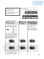
To set the flow meter alarm:
3
Adjust flow meter
alarm setting.
4
Turn on hot
water.
Press the flow meter alarm set button
(the setting will flash on the display)
and adjust with the setting buttons.
5
Turn off the hot
water when the
alarm sounds.
The alarm will sound when
the set level has been
reached. Stop the water.
Increase
Note:
The alarm will not sound
if it is set for 990 gallon.
Decrease
Choose the flow meter alarm setting from the following
options: 10 - 60 gallon (40 - 240L) (In 5 gallon (20L)
intervals), 70 gallon (260L), 80 gallon (300L),
90 gallon (340L), 100 gallon (380L) , 990 gallon.
Note:
The alarm will not sound if it is
set for 990 gallon.
On
Off
On
Off
Flow meter setting will be flashing
(ex. 45 gallon)
Flow meter setting will be flashing (ex. 180L)
* The level can only be adjusted
while the indicator is flashing.
* After ten seconds, the remote will
again display the temperature.
15
How to Use
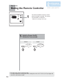
Muting the Remote Controller
1
The remote controller will emit a sound
when any button is pushed. This sound
can be muted if it is desired.
* Initial factory setting is with sound.
1
Hold the Power On/Off
Button for five seconds.
Muted
No sound
after 5 sec.
Sound
Tone sounds
after 5 sec.
r5IFáPXNFUFSBMBSNDBOOPUCFNVUFE
r5IFIJHIUFNQFSBUVSFXBSOJOHUPOFXIFOTFUUJOHUIFVOJUUP'$'
PSIJHIFSXJMM
not emit a sound when muted.
16
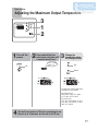
How to Use
Adjusting the Maximum Output Temperature
3
1
2
1
Turn off the
power.
2
Press and hold the flow
meter alarm set button until
a sound is heard (2 sec.).
3
Tone sounds
after 2 sec.
Off
Change the
temperature using
the setting buttons.
Up
Down
The upper limit of the hot-water supply
temperature can be changed to
(For Fahrenheit (°F))
100°F, 105°F, 110°F, 115°F, 120°F,
125°F, 130°F, 135°F or 140°F.
(For Celsius (°C))
37°C, 38°C, 39°C, 40°C, 41°C, 42°C,
43°C, 44°C, 45°C, 46°C, 47°C, 48°C,
50°C, 55°C or 60°C.
4
Set the Power button to ON when continuing to use
the unit as is. Otherwise, let the unit sit for 30 sec.
17
Preventing Damage from Freezing-1
CAUTION
* Damage can occur from frozen water within the device and pipes even in warm environments.
Be sure to read below for appropriate measures.
* Repairs for damage caused by freezing are not covered by the warranty.
Freezing is prevented within the device automatically by the freeze-prevention heater.
Freezing cannot be prevented when the power plug is unplugged. Do not remove the power
plug from the wall outlet.
Freezing will be prevented regardless of whether the operation switch is ON or OFF.
* In normal operation, freezing is prevented within the device automatically unless the outside
temperature without wind is below -30°F (-35°C).
- When supplying combustion air from the indoors, the room temperature must be greater than
32°F (0°C) to prevent freezing and the room inside must not have negative pressure.
* The freeze prevention heaters will not prevent the plumbing external to the unit from freezing.
Protect this plumbing with insulation, heat tape or electric heaters, solenoids, or pipe covers.
If there remains a freezing risk, contact the nearest Electrolux agent.
Take the measures below for extremely cold temperatures*.
Outside temperature including wind chill factor less than -30°F (-35°C).
- When supplying combustion air from the indoors, the room temperature must be greater than
32°F (0°C) to prevent freezing and the room inside must not have negative pressure.
This method can protect not only the heater, but also the water supply, water piping and mixing valves.
1. Turn off the power.
2. Close the gas supply valve.
Hot Water Fixture
3. Open a hot water fixture, and keep a small stream of hot water
SVOOJOHHBMMPODD
NJOVUFPSBCPVUNN
UIJDL
* If there is a mixing valve, set it to the highest level.
* When linking multiple units, discharge water equivalent to
HBMMPODD
NJOVUFQFSVOJU
4. The flow may become unstable from time to time.
NN
Check the flow 30 minutes later.
thick
* In general, it is not advisable to run water through the unit when
it is OFF ( p. 6), but in this case freeze prevention is more important.
* Remember to set mixing valves and fixtures to their original levels before using the unit again
to prevent scalding.
* If there is still a risk that the unit will freeze, drain the unit as shown on the pages 19, 20.
If water will not flow because it is frozen
1. Close the gas and water valves.
2. Turn off the power button.
3. Open the water supply valve from time to time to check whether water is running.
4. When the water is flowing again, check for water leaks from the equipment and piping before using.
If the heater or the piping is frozen, do not use the heater or it may get damaged.
18
Preventing Damage from Freezing-2
For EN18WI30LS, EP18WI30LS
If the water heater will not be used for a long period of time,
drain the water.
Drain the water as follows:
CAUTION
High Temperature
To avoid burns, wait until the equipment cools
down before draining the water. The appliance
will remain hot after it is turned off.
Drain water into a bucket to prevent water damage.
Manual Draining
1
2
3
4
5
6
7
Close the gas valve.
Turn off the power button.
Off
Disconnect the electrical power supplied to the unit.
Do not touch with wet hands.
Close the water supply valve.
Fully open all hot water fixtures.
Fixture
Turn the drain plug to the left to open, and then remove.
Allow a minimum of 10 minutes for water to drain out of the unit.
Check that the water is completely drained.
When completely drained, replace all drain plugs
and close the hot water fixtures.
Drain Plugs
Each drain plug might not be visible if
insulation is installed around the piping.
19
Preventing Damage from Freezing-3
For EN19WI30LS, EP19WI30LS
If the water heater will not be used for a long period of time, drain the water.
Drain the water as follows:
CAUTION
High Temperature
To avoid burns, wait until the equipment cools down
before draining the water. The appliance will remain
hot after it is turned off.
Drain water into a bucket to prevent water damage.
Drainage Using the Remote Controller
1
5VSOUIFQPXFSPOPGG
CVUUPOiPGGu
(2) Press the flow meter alarm set
button for about two seconds
until the alarm sounds.
The maximum hot water
temperature will flash.
(Ex. 120°F)
Manual Draining
1
2
(3) Press the flow meter alarm
set button again.
(4) Press the setting button
NBSLFEiu. The display will
DIBOHFGSPNP'UPPOBGUFS
the button is pushed.
2
3
4
5
6
3
Close the water supply
valve.
Close the gas valve.
5VSOUIFQPXFSPOPGGCVUUPOi0Ou
Fixture
(2) Turn and leave open
the hot water fixtures
for more than 2 minutes
and close.
* If multiple units are being used,
drain two minutes for each unit.
* An 11 Error Code may appear on
the remote controller.
This is not a malfunction of the unit.
%POPUUVSO1PXFS0/0''#VUUPO0''
Close the water supply
valve and disconnect
the electrical power
supplied to the unit.
Do not touch with wet hands.
Fully open all hot water fixtures.
Fixture
Open all drain plugs and drain the water out of
the unit.
When the water is completely drained, replace
all drain plugs and close the hot water fixtures.
4
5
6
Fully open all
hot water fixtures.
Fixture
Open all drain plugs and drain the
water out of the unit.
When the water is completely
drained, replace all drain plugs and
close the hot water fixtures.
Close the gas valve and disconnect
the electrical power supplied to the unit.
Do not touch with wet hands.
Drain Plugs
20
Each drain plug might not be visible if
insulation is installed around the piping.
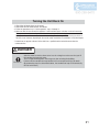
Turning the Unit Back On
1.
2.
3.
4.
Check that all drain plugs are inserted.
Check that all hot water fixtures are closed.
'PMMPXUIFQSPDFEVSFPOQi*OJUJBMPQFSBUJPOuTUFQTUISPVHI
Make sure that the area around the appliance is well ventilated; open a window or a door if necessary.
Then, operate the unit and verify that condensate is coming out of the drain pipe.
(During normal use of the water heater, condensate will begin to discharge from the drain pipe within 15
NJOVUFTPGVTF)PXFWFSEFQFOEJOHPOUIFTFBTPOBOEPSJOTUBMMBUJPOTJUFDPOEJUJPOTJUNBZUBLFMPOHFS
* If water does not appear at the end of the drain line, a qualified service technician must clean the
condensate line.
DANGER
Be sure to do.
After the water heater has been out of use for a long time make sure that you fill
the condensate trap with water.
This is to prevent dangerous exhaust gases from entering the building.
Failure to fill the condensate trap could result in severe personal injury or death.
(By performing step 4 as described above, the condensate trap will automatically
fill itself with water.)
21
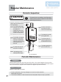
Regular Maintenance
Periodic Inspection
CAUTION
To prevent burns or scalding, turn off the power
button and wait until the equipment cools before
performing maintenance.
Be sure to do.
[When supplying combustion air
from the indoors]
air supply vent
Check For smear or blockage
Check For dust and soot in
with dust, oil, etc. at the
air supply vent.
If blocked, remove the
build-up with a vacuum
cleaner or damp towel.
the exhaust vent or
exhaust vent terminal.
* Do not permanently remove the Inlet Screen.
Check For abnormal sounds
during operation.
Check For laundry, newspaper,
timber, oil, spray cans
and other combustible
materials near the heater
or the exhaust vent
terminal.
Check For abnormalities in
external appearance,
discoloration or flaws.
Check For proper operation of
Check For water leaks from the
pressure relief valve.
equipment and piping.
Check For blockage at the
drain pipe discharge.
(Ex. EN18WI30LS)
Periodic Maintenance
Equipment
Wipe the outside surface with a wet cloth, then dry the surface. Use a neutral detergent to clean any stains.
If an external condensate neutralizer is installed, periodic replacement of the neutralizing agent will be required.
Refer to the instructions supplied with the neutralizer for suggested replacement intervals.
Remote Controller
Wipe the surface with a wet cloth.
r %POPUVTFCFO[FOFPJMPSGBUUZEFUFSHFOUTUPDMFBOUIFSFNPUFDPOUSPMMFS
deformation may occur.
r 5IFSFNPUFDPOUSPMMFSJTXBUFSSFTJTUBOUCVUOPUXBUFSQSPPG,FFQJUBTESZBTQPTTJCMF
22
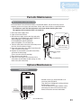
Periodic Maintenance
Water Drain Valve (with Water Filter)
If the water drain valve (with water filter) is covered with debris, the hot water may not run
smoothly, or the unit may put out cold water. Check and clean the filter as explained below.
* To avoid burns, wait until the equipment cools down before draining the water.
The appliance will remain hot after it is turned off.
1. Close the water supply valve.
2. Open all hot water fixtures.
3. With a bucket ready, remove the inlet and outlet
drain plugs (For EN18WI30LS and EP18WI30LS,
about 0.4 gallon (1.4L) will drain out.
For EN19WI30LS and EP19WI30LS,
about 0.45 gallon (1.7L) will drain out.)
4. Take the water drain valve (with water filter) out of
the inlet. (See illustration to right).
5. Clean the water drain valve (with water filter) with
a brush under running water.
6. Replace the water drain valve (with water filter)
and close the drain plugs.
(Take care not to lose the packing.)
7. Close all hot water fixtures.
8. Open the water supply valve and check that
water does not leak from the drain plugs or water
drain valve (with water filter).
Inlet
Packing
Water drain valve
(with water filter)
Water Supply
Valve
(Ex. EN18WI30LS)
Optional Maintenance
Isolation Valves
* Isolation valves may be purchased as an
accessory from Electrolux.
They allow for full diagnostic testing and easy
flushing of the system.
* The kit includes two full port isolation valves
and a pressure relief valve for the hot side.
Contact Electrolux for more information.
Hot Water
Service Valve
Pressure Relief Valve
Cold Water
Service Valve
Water Intlet
Drain
Water Outlet
(Ex. EN18WI30LS)
23
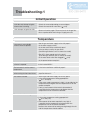
Troubleshooting-1
Initial Operation
Unit does not attempt to ignite
when water is running.
r$IFDLGPSSFWFSTFEQMVNCJOHPSDSPTTFEQJQFT
r$IFDLUIFXBUFSESBJOWBMWFàMUFS p.23)
Unit attempts to ignite but fails.
r3FTFUVOJUBOEUSZBHBJO5IFSFNBZCFBJSJOUIFHBTMJOF
r)BWFBQSPGFTTJPOBMDIFDLUIFHBTTVQQMZQSFTTVSF
Temperature
Hot water is not available
when a fixture is opened.
r"SFUIFHBTBOEXBUFSTVQQMZWBMWFTGVMMZPQFO
r*TUIFXBUFSTVQQMZDVUPGG
r*TUIFIPUXBUFSàYUVSFTVGàDJFOUMZPQFO
r*TUIFHBTCFJOHDVUPGGCZUIFHBTNFUFS
$BOPUIFSHBTEFWJDFTTVDIBTTUPWFTCFVTFE r'PS-1
*TUIFSFFOPVHIHBTJOUIFUBOL $BOPUIFSHBTEFWJDFTTVDIBTTUPWFTCFVTFE r*TUIFXBUFSESBJOWBMWFàMUFSDMPHHFE p.23)
r*TUIFQPXFSCVUUPOUVSOFEPO
No water is available when
a fixture is opened.
r*TUIFXBUFSTVQQMZDVUPGG
r*TUIFIFBUFSGSP[FO
The hot water is not the correct
temperature.
r*TUIFIPUXBUFSàYUVSFTVGàDJFOUMZPQFO
Water takes time to become hot
when turning the hot water fixture.
r)BWFZPVBMMPXFEFOPVHIUJNFGPSUIFDPMEXBUFSJOUIF
QJQFTUPESBJOPVU
The water is too hot.
r"SFUIFHBTBOEXBUFSTVQQMZWBMWFTGVMMZPQFO
r*TUIFXBUFSUFNQFSBUVSFTFUUJOHBQQSPQSJBUF ( p.12 and p.13)
r*GUIFXBUFSTVQQMZUFNQFSBUVSFJTIJHIJUJTQPTTJCMFGPSUIF
temperature to be higher than the temperature set on the
remote controller.
r*GPOMZBTNBMMBNPVOUPGIPUXBUFSJTEFNBOEFEJU
is possible for the temperature to be higher than the
temperature set on the remote controller.
The water is not hot enough.
r"SFUIFHBTBOEXBUFSTVQQMZWBMWFTGVMMZPQFO
r*TUIFXBUFSUFNQFSBUVSFTFUUJOHBQQSPQSJBUF ( p.12 and p.13)
r*GUIFBNPVOUPGIPUXBUFSSFRVJSFEJTWFSZIJHIJU
is possible for the temperature to be lower than the
temperature set on the remote controller.
Decrease the amount of hot water passing through the unit
and the temperature should stabilize.
24
The water is cold when only a
single fixture is open.
r5IFVOJUXJMMOPUIFBUUIFXBUFSJGUIFáPXSBUFJTMFTTUIBO
0.5 gallons (2L) per minute.
Open the fixture more or open other fixtures so that a
greater flow passes through the unit, and the unit should
begin heating again.
Fluctuations in hot water
temperatures.
r4FUXBUFSUFNQFSBUVSFBU°F to 120°F or 48°C (118°F) to
50°C (122°F). This will allow you to use a higher flow of hot
water thus meeting the minimum flow requirement of 0.5
(1.-NJO
r$MFBOUIFXBUFSàMUFSPGBOZEFCSJT ( p.23)
Setting temperature cannot rise.
r*TUIFNBYJNVNUFNQFSBUVSFTFUUJOHBQQSPQSJBUF (
p.17)
Amount of Hot Water
The amount of hot water at a
certain fixture is not constant.
rWhen hot water is demanded at other fixtures, the amount
available may be reduced. The maximum flow available from
UIF&/8*-4&18*-4JT(1.-NJO
at a
45°F (25°C) temperature rise. The maximum flow available
GSPNUIF&/8*-4&18*-4JT(1.-NJO
BU
a 45°F (25°C) temperature rise.
r1SFTTVSFáVDUVBUJPOTBOEPUIFSQMVNCJOHDPOEJUJPOTDBO
cause the temperature and pressure at a fixture to be
unstable, but it should stabilize after a short time.
r5IFSF BSF TPNF UZQFT PG IPU XBUFS UBQT UIBU EJTDIBSHFT
large volumes of hot water at first but stabilize after time.
r5PLFFQUIFUFNQFSBUVSFTUBCMFUIFIFBUFSMJNJUTUIF
amount of water that can flow through it to a small amount
initially, but the amount increases over time.
The amount of hot water in the tub
JTMFTTNPSFUIBOUIFTFUBNPVOU
r8IFOIPUXBUFSJTVTFEGPSPUIFSàYUVSFTXIJMFàMMJOHUIF
bath tub, the tub will not fill as much.
rIf there is water in the tub already, or when filling is stopped
and restarted, the tub will fill more.
The flow meter alarm does not
sound even when filled to the set
amount.
r5IFáPXNFUFSBMBSNJTTFUUPTPVOEXIFOIPUXBUFS
is continuously discharged for the set volume of water.
If mixing valves are used, or if cold water is mixed with hot
water at the fixture, the tub will fill more than the setting
of the flow meter alarm.
Amount of hot water available
has decreased over time.
r*TUIFXBUFSàMUFSDMPHHFE p.23)
r*GUIFTVQQMZXBUFSJTIBSEBOEIBTOPUCFFOUSFBUFE
scale can build-up in the water heater and decrease
the maximum amount of hot water available. Scale can
be removed from the water heater by flushing the unit
periodically. To prevent scale from forming in the water
heater, a water softener or scale inhibitor is recommended.
25
Troubleshooting-2
Remote Controller
The light on the power button
does not come on.
r)BTUIFSFCFFOBQPXFSGBJMVSF
The water temperature changes
after a power failure or when the
power is disconnected.
r5IFUFNQFSBUVSFTFUUJOHBOEUIFáPXNFUFSBMBSNTFUUJOH
may both need to be reset after a power outage.
r*TUIFQPXFSDPOOFDUFEQSPQFSMZ
The plastic on the surface or buttons rThe surface of the remote controller is affixed with a
protective sheet (to prevent surface scratching, etc.) at
of the remote controller has torn,
time of shipment. This sheet can be removed or left as it
peeled, or air bubbles inside.
is. When leaving the protective sheet on, areas frequently
touched may tear or peel. However, the remote controller
will not malfunction from water entering such torn or peeled
areas. To restore the appearance of the remote controller
surface, simply remove the protective sheet.
Sounds
The fan can be heard after
operation is stopped.
A motor can be heard when turning
the unit ON or OFF, when opening
or closing a fixture, or after the unit
has been running for a while.
r5IFTFOPJTFTJOEJDBUFUIFQSPQFSPQFSBUJPOPGEFWJDFT
which are designed to let the unit reignite more quickly,
and ensure the water temperature is stable.
The fan can be heard when it is
very cold outside.
rThe fan may run to prevent freezing.
Other
The Heater stops burning during
operation.
26
r"SFUIFHBTBOEXBUFSTVQQMZWBMWFTGVMMZPQFO
r*TUIFXBUFSTVQQMZDVUPGG
r*TUIFIPUXBUFSàYUVSFTVGàDJFOUMZPQFO
r*TUIFHBTCFJOHDVUPGGCZUIFHBTNFUFS $BOPUIFSHBTEFWJDFTTVDIBTTUPWFTCFVTFE r'PS-1
*TUIFSFFOPVHIHBTJOUIFUBOL $BOPUIFSHBTEFWJDFTTVDIBTTUPWFTCFVTFE White smoke comes out of the
exhaust vent on a cold day.
r5IJTJTOPSNBM5IFXIJUFTNPLFJTBDUVBMMZTUFBN
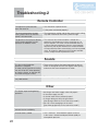
The hot water is turbid.
r5IJTJTIBSNMFTT4NBMMCVCCMFTBQQFBSBTUIFBJS
in the water is heated and depressurized rapidly to
atmospheric pressure.
The water appears blue.
r$PMPSBUJPOUPBCMVFDPMPSNBZCFOPUJDFEGSPNTNBMM
5IFCBUIUVCXBTICBTJOIBTUVSOFE traces of copper ion contained in the water and fat
(furring). However, there are not problems concerning
blue.
IFBMUI$PMPSBUJPOPGUIFCBUIUVCXBTICBTJODBOCF
prevented by cleaning frequently.
r$POEFOTBUJPOGPSNTJOTJEFUIFVOJUEVSJOHPQFSBUJPO
and is discharged from the drain pipe.
Frequent water discharge from the
drain pipe.
åÃè·ï\é¶Ç¼Ç®í≤Ç◊Ç≠ÇæÇ≥Ç¢
åÃè·ï\é¶Ç¼Ç®í≤Ç◊Ç≠ÇæÇ≥Ç¢
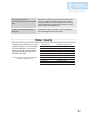
Water Quality
Damage to the water heater as a result
of poor water quality is not covered by
the Limited Warranty. To ensure full
warranty coverage, treat or condition
water that exceeds the target levels
provided in this table.
Source: EPA National Secondary Drinking Water
Regulations (40 CFR Part 143.3)
Total Hardness*
"MVNJOVN
$IMPSJEF
$PQQFS
*SPO
.BOHBOFTF
pH
5PUBM%JTTPMWFE4PMJET
;JOD
4VMGBUFJPO
3FTJEVBMDIMPSJOF
: NH-HQH
PSMFTT
UPNH-PSMFTT
NH-PSMFTT
NH-PSMFTT
NH-PSMFTT
NH-PSMFTT
: 6.5 - 8.5
NH-PSMFTT
NH-PSMFTT
NH-PSMFTT
NH-PSMFTT
* Maximum limit suggested by Electrolux.
27
åÃè·ï\é¶Ç¼Ç®í≤Ç◊Ç≠ÇæÇ≥Ç¢
åÃè·ï\é¶Ç¼Ç®í≤Ç◊Ç≠ÇæÇ≥Ç¢
Check for an Error Code on the Remote Controller
If there is a problem with the unit, a numerical error code will flash on the remote controller.
If this occurs, take appropriate measures as listed below.
Flashing
When an error code appears, the display and the operation light will
flash together.
Remote Controller
Error Code
Cause
Action
Ignition error
Check whether the gas valve is open. Press the power
button to turn the unit off, open a hot water fixture,
and turn the unit back on. If the flashing number
doesn't return the problem is solved.
Clogging of condensate
trap or drain pipe
Check to see if the condensate drain pipe is clogged
p.8)
or frozen (
Contact the installer or Electrolux Home Products,
Inc. Technical Support for assistance.
[When supplying combustion
air from the indoors]
The air supply vent may
be clogged
Clean the air supply vent.(
p.21)
If the display continues, contact the nearest
Electrolux agent.
Abnormal combustion,
low gas supply pressure
Have a professional check the gas supply pressure.
Contact the nearest Electrolux agent.
Abnormal combustion
Contact the nearest Electrolux agent.
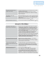
Contact Electrolux Home Products, Inc. if:
r "OZPUIFSFSSPSDPEFBQQFBST
r "OFSSPSDPEFJTJOEJDBUFEBHBJOBGUFSUIFBCPWFBDUJPOTXFSFGPMMPXFE
r 5IFSFBSFBOZPUIFSRVFTUJPOT
28
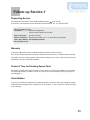
Follow-up Service-1
Requesting Service
First follow the instructions in the troubleshooting section (
p.24 to p.28).
If the error is not corrected, contact Electrolux Home Products, Inc. at 1-888-360-8557.
We will need to know:
The Model ................(check the rating plate)
See p.4 for the location of the label
Date of purchase ......(see the warranty)
Details of problem ....(flashing error codes, etc., in as much detail as possible)
Your name, address, and telephone number
Desired date of visit
Warranty
A warranty registration card is included separately, read the content carefully.
Be sure that the plumber, date of purchase and other necessary items are filled in prior to mailing.
For repairs after the warranty period, there will be a charge on any service, and service will only be
performed if the unit is deemed repairable.
Period of Time for Stocking Repair Parts
Electrolux will stock repair and maintenance parts for this unit for the time period from the date of
the original installation as follows: twelve (12) years for the heat exchanger and ten (10) years for
remaining parts.
Reinstallation
If you want to reinstall the appliance at a different location, confirm that the gas and power supply
indicated on the rating plate are available at the new location. If you are not sure, consult the local
utility company.
29
Follow-up Service-2
Gas Conversion
If you move to a region that uses a different type of gas or if the local gas supply is converted,
replacement of the gas manifold and adjustment of the appliance will be necessary.
This work must be performed by either Electrolux or a qualified service agency and will be charged
for even during the warranty period. The qualified installer will also be responsible for purchasing
the gas conversion kit directly from the manufacturer.
For more information, contact Electrolux Home Products, Inc. at 1-888-360-8557.
WARNING
The gas conversion kit shall be installed by a qualified service agency* in accordance with
the manufacturer’s instructions and all applicable codes and requirements of the authority
having jurisdiction. The information in the instructions must be followed to minimize the risk
of fire or explosion or to prevent property damage, personal injury, or death. The qualified
service agency is responsible for the proper installation of this kit. The installation is not
proper and complete until the operation of the converted appliance is checked as specified
in the manufacturer’s instructions supplied with the kit.
* A qualified service agency is any individual, firm, corporation, or company which either in person or
through a representative is engaged in and is responsible for the connection, utilization, repair or servicing
of gas utilization equipment or accessories; who is experienced in such work, familiar with all precautions
required, and has compiled with all of the requirements of the authority having jurisdiction.
Before the gas conversion is performed, verify the proper gas conversion kit with your
water heater model on the table provided below.
$POWFSTJPO,JU
Model
Conversion Type
$,
EP18WI30LS
Propane to Natural Gas
$,
EN18WI30LS
Natural Gas to Propane
$,
EP19WI30LS
Propane to Natural Gas
$,
EN19WI30LS
Natural Gas to Propane
The following parts are supplied in the conversion kit. These items will replace the existing parts
that are currently installed in the unit. Make sure that all parts are replaced and properly installed by
a qualified service agency.
* An Electrolux remote controller and a digital gas manometer are required to complete the
installation. Do not proceed if this equipment is not immediately available.
Manifold Plate
O-Ring
Damper
$POWFSTJPO,JU-BCFM
After the necessary parts have been replaced on the unit, the remote controller is then used to
adjust the settings on the water heater for use with the proper gas type.
The gas pressure values at both the gas supply inlet fitting and at the manifold inlet on the unit are
verified by the installer. Proper adjustments will be made to ensure safe and efficient operation.
Once this is completed, a final gas leak check will be performed to confirm that all parts have been
securely installed.
If you notice the smell of gas at any time after the installation has been completed, turn the water
heater off and contact your gas supplier immediately.
30
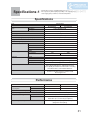
Specifications-1
r4QFDJàDBUJPOTNBZCFDIBOHFEXJUIPVUQSJPSOPUJDF
r5IFDBQBDJUZNBZEJGGFSTMJHIUMZEFQFOEJOHPOUIFXBUFSQSFTTVSF
water supply, piping conditions, and water temperature.
Specifications
Specification
Item
Model Name
Type
Installation
"JS4VQQMZ&YIBVTU
Ignition
Operating Pressure
Minimum Flow Rate
Dimensions (Height) x (Width) x (Depth)
Weight
Water Holding Capacity
Connection Sizes
Water Inlet
Hot Water Outlet
Gas Inlet
Condensate Drain
Supply
Power Supply
Consumption
Materials
Casing
Flue Collar
Primary Heat Exchanger
Secondary Heat Exchanger
Safety Devices
EN18WI30LS
EP18WI30LS
Indoor Wall Mounted
Power Vented
Direct Ignition
15-150 psi
(1.-NJO
NN
YNN
YNN
58 lbs.
0.5 Gallon (1.8L)
u
u
u5ISFBEFE
120 VAC (60Hz)
78W
73W
Freeze Prevention 213W
4UBJOMFTT4UFFM;JODJàFE4UFFM1MBUF
PVC
Copper Sheeting, Copper Tubing
Stainless Steel Sheeting, Stainless Steel Tubing
Flame Rod, Thermal Fuse, Lightning Protection
Device (ZNR), Overheat Prevention Device, Freezing
Prevention Device, Fan Rotation Detector
Accessories
Remote Controller, Remote Controller Cord,
Anchoring Screws
Performance
Item
Gas
Consumption
Maximum Hot Water Capacity
NG
LP
45°F (25°C) Rise
Capacity Range
Temperature Settings
°F Mode:
°C Mode:
Default Temperature Options
Maximum Performance
180,000 btuh
180,000 btuh
Minimum Performance
16,000 btuh
16,000 btuh
(1.-NJO
(1.-NJO
100-140°F (In 5°F intervals) (9 Options)
37-48°C (In 1°C intervals),
50,55,60°C (In 5°C intervals) (15 Options)
120°F (50°C), 130°F (55°C), 140°F (60°C)
(Original is 120°F (50°C))
31
Specifications-2
r4QFDJàDBUJPOTNBZCFDIBOHFEXJUIPVUQSJPSOPUJDF
r5IFDBQBDJUZNBZEJGGFSTMJHIUMZEFQFOEJOHPOUIFXBUFSQSFTTVSF
water supply, piping conditions, and water temperature.
Specifications
Specification
Item
Model Name
Type
Installation
"JS4VQQMZ&YIBVTU
Ignition
Operating Pressure
Minimum Flow Rate
Dimensions (Height) x (Width) x (Depth)
Weight
Water Holding Capacity
Connection Sizes
Water Inlet
Hot Water Outlet
Gas Inlet
Condensate Drain
Supply
Power Supply
Consumption
Materials
Casing
Flue Collar
Primary Heat Exchanger
Secondary Heat Exchanger
Safety Devices
EN19WI30LS
EP19WI30LS
Indoor Wall Mounted
Power Vented
Direct Ignition
15-150 psi
(1.-NJO
NN
YNN
YNN
68 lbs.
0.5 Gallon (1.8L)
/15
/15u
/15u
u5ISFBEFE
120 VAC (60Hz)
83W
81W
Freeze Prevention 223W
4UBJOMFTT4UFFM;JODJàFE4UFFM1MBUF
PVC
Copper Sheeting, Copper Tubing
Stainless Steel Sheeting, Stainless Steel Tubing
Flame Rod, Thermal Fuse, Lightning Protection
Device (ZNR), Overheat Prevention Device, Freezing
Prevention Device, Fan Rotation Detector
Remote Controller, Remote Controller Cord,
Anchoring Screws
Accessories
Performance
Item
Gas
Consumption
Maximum Hot Water Capacity
NG
LP
45°F (25°C) Rise
Capacity Range
Temperature Settings
°F Mode:
°C Mode:
Default Temperature Options
32
Maximum Performance
199,900 btuh
199,900 btuh
Minimum Performance
16,000 btuh
16,000 btuh
(1.-NJO
(1.-NJO
100-140°F (In 5°F intervals) (9 Options)
37-48°C (In 1°C intervals),
50,55,60°C (In 5°C intervals) (15 Options)
120°F (50°C), 135°F (57°C), 140°F (60°C)
(Original is 120°F (50°C))
Electrolux Home Products, Inc
Limited Warranty
Tankless Hot Water Heaters
!=:;=)6<<7<0-<-:5;)6,+76,1<176;;-<.7:<016<01;151<-,')::)6<A<01;D')::)6<AE4-+<:74=@75-!:7,=+<;6+D4-+<:74=@
0-:-*A?)::)6<;<7<0-7:1/16)4+76;=5-:8=:+0);-:16<0-7:1/16)44A16;<)44-,47+)<176<0-D ?6-:<0--6+47;-,/);07<?)<-:
0-)<-:<0-D!:7,=+<E<7*-.:--.:75)6A5)<-:1)4,-.-+<;165)<-:1)4;)6,?7:35)6;018%0-:-):-67-@8:-;;?)::)6<1-;7<0-:
<0)6<07;-+76<)16-,16<01;')::)6<A)6,)44:-8:-;-6<)<176;7:).F:5)<176;5),-*A4-+<:74=@7:)6A7<0-:8-:;76?-:-.7:
144=;<:)<1>-8=:87;-;764A7)/-6<-5847A--7::-8:-;-6<)<1>-7.4-+<:74=@0);)6A)=<07:1<A<7*16,4-+<:74=@<7)6A).F:5)<176
:-8:-;-6<)<1767:?)::)6<A+76+-:616/<0-!:7,=+<)6,=64-;;)6).F:5)<176:-8:-;-6<)<1767:?)::)6<A5),-*A)6)/-6<
-5847A--7::-8:-;-6<)<1>-1;;8-+1F+)44A16+4=,-,?1<016<01;')::)6<A1<?14467<*--6.7:+-)*4-*A<0- ?6-:
Required Conditions
%0- ?6-:5=;<8:7>1,-8:77.7.8=:+0);-)6,+7584-<-<0-!:7,=+<#-/1;<:)<176')::)6<A):,D#-/1;<:)<176
):,E+76<)16-,?1<016<0-41<-:)<=:-8:7>1,-,7::-/1;<-:76416-*A/716/<7-4-+<:74=@)8841)6+-;+757:+)4416/
%0-!:7,=+<5=;<*-16;<)44-,*A)64-+<:74=@=<07:1B-,6;<)44-:16+75841)6+-?1<04-+<:74=@8=*41;0-,5)<-:1)4;
8:7>1,-,?1<0<0-!:7,=+<)6,16)++7:,)6+-<7)4447+)484=5*16/-4-+<:1+)4)6,7:/);+7,-;
%0- ?6-:5=;<=;-<0-!:7,=+<16+75841)6+-?1<016;<:=+<176;16<0-6;<)44)<176)6=)4)6,&;-):-=1,-
?01+0):-16+4=,-,?1<0<0-!:7,=+<
Limited Warranty Period
%01;')::)6<A1;-@<-6,-,*A4-+<:74=@<7<0- ?6-:%01;')::)6<A<)3-;-..-+<76<0-,)<-7.16;<)44)<1767.<0-!:7,=+<*A<0-
4-+<:74=@=<07:1B-,6;<)44-:7:,)A;).<-:<0-,)<-7.8=:+0);-?01+0->-:7++=:;F:;<)6,1;-..-+<1>-=6<14<0-;8-+1F-,
)661>-:;):A7.;=+0,)<-);.7447?;
151<-, 6-(-):)88:7>-,4)*7: )6,:-84)+-5-6<7.,-.-+<1>-8):<;
151<-,),,1<176)47=:(-)::-84)+-5-6<A-):;<0:7=/07.,-.-+<1>-8):<;7<0-:<0)6<0-0-)<-@+0)6/-:C
)*7:67<16+4=,-,
151<-,),,1<176)44->-6(-): :-84)+-5-6<A-):;<0:7=/0
76<0-0-)<-@+0)6/-:?0-6<0-!:7,=+<1;=;-,16
);16/4-.)514A,?-4416/C)*7:67<16+4=,-,
151<-,),,1<176)44->-6(-): :-84)+-5-6<A-):;<0:7=/0
76<0-0-)<-@+0)6/-:?0-6<0-!:7,=+<1;=;-,16
);16/4-.)514A,?-4416/16+762=6+<176?1<0)+76<:744-: :-+1:+=4)<176;A;<-516;<)44-,16)++7:,)6+-?1<0<0-
6;<)44)<176)6=)4C)*7:67<16+4=,-,
151<-,),,1<176)4%?7(-)::-84)+-5-6<A-):;<0:7=/076<0-0-)<-@+0)6/-:?0-6<0-!:7,=+<1;=;-,.7:
+755-:+1)4+)8)+1<A1.1<1;=;-,167<0-:<0)6);16/4-.)514A,?-4416/7:1.<0-!:7,=+<1;;=8841-,?1<08:-0-)<-,7:
+1:+=4)<-,?)<-:C)*7:67<16+4=,-,
)*7:?144*-8)1,<7)6=<07:1B-,4-+<:74=@$-:>1+-#-8:-;-6<)<1>-76)88:7>-,?)::)6<A:-8)1:;
%7<)4%?-4>-(-):A-):;
<0:7=/0
7:78-:)<176)4*=:607=:;);:-+7:,-,*A<0-?)<-:0-)<-:?01+0->-:7++=:;F:;<
6)9=);<)<1;<0-51615=58=58+76<:74:-9=1:-5-6<167:,-:<75)16<)16<0-.=44:-+1:+=4)<176?)::)6<A!716<7.=;-7:D76,-5)6,E:-+1:+=4)<176;A;<-5;
?01+0):-<0-:5)44A+76<:744-,1-)9=);<)<)4;7+4);;1.A);+76<:744-,;A;<-5;
Exclusions
!4-);-:-.-:<7<0-6;<)44)<176)6=)4)6,&;-):-)6=)4;=8841-,?1<0A7=:6-?4-+<:74=@8:7,=+<%01;')::)6<A*-+75-;
6=44)6,>71,1.)6A7.<0-.7447?16/):-,-<-:516-,<7*-+76<:1*=<16/.)+<7:;<7.)14=:-7.<0-!:7,=+<=6,-:<01;')::)6<A
*=;-6-/4-+<51;=;-7:51;)8841+)<176
58:78-:,)6/-:7=;7:,-;<:=+<1>-5)16<-6)6+-8:7+-,=:-;
)5)/-;+)=;-,*A;-:>1+-;8-:.7:5-,*A;-:>1+-:;7<0-:<0)64-+<:74=@7:1<;)=<07:1B-,;-:>1+-:;
&;-16+762=6+<176?1<0)6A=6)88:7>-,,->1+-
6;<)44)<17616)6-6>1:765-6<<0)<1;+7::7;1>-7:7<0-:?1;-,-;<:=+<1>-<7<0-8:7,=+<?0-<0-:16<-:6)47:-@<-:6)4
6+7::-+</);7:?)<-:8:-;;=:-
6+7::-+<;1B16/.7:<0-)8841+)<176
&;-?1<0158:78-:/);<A8-
!:7,=+<?1<07:1/16)4;-:1)46=5*-:;<0)<0)>-*--6:-57>-,7:)4<-:-,)6,+)667<*-:-),14A,-<-:516-,
)5)/-);):-;=4<7..:--B16/?1<016<0-=61<7:;=::7=6,16/81816/
)5)/-);):-;=4<7.=;-?1<067687<)*4-?)<-:=6<:-)<-,7:877:4A<:-)<-,?-44?)<-:7:?)<-:?1<001/0!
4->-4;7:0):,6-;;4->-4;16-@+-;;7.
/:)16;8-:/)44765/#-.-:<7<0-D')<-:"=)41<AE;-+<1767.<0-&;-
):-=1,-.7:,-<)14;
$-:>1+-+)44;?01+0,767<16>74>-5)4.=6+<1767:,-.-+<;16?7:35)6;0187:5)<-:1)4%0-+76;=5-:?1448)A.7:
;=+0;-:>1+-+)44;
+<;7.7,16+4=,16/*=<67<4151<-,<7F:-G77,7:6)<=:)4,1;);<-:
76<16=-,
33
<,+1&+2"!=
+1%""3"+1,#+)" 1/,)25/" ,$+&7"!!"#" 1*)#2+ 1&,+,/#&)2/"1, ,+#,/*4&1%1%&0//+16+!0"!2-,+)" 1/,)25
--/,3),#4//+16 )&*)" 1/,)251&100,)"+!0,)21"!&0 /"1&,+4&))0"11)"1%"4//+16 )&*,#02 %!"#" 1*)#2+ 1&,+
,/#&)2/"1, ,+#,/*4&1%1%&0//+16+,/!"/1,*(" )&*2+!"/1%&0//+161%"4+"/*201+,1)" 1/,)25,/&10
21%,/&7"!/"-/"0"+11&3",#1%"#&)2/",#1%"/,!2 11, ,+#,/*1,1%&0//+16
+!"/1%&0//+16)" 1/,)254&)),+)6-/,3&!"/"-) "*"+1-/100!"0 /&"!&+1%"8&*&1"!//+16"/&,!9%"4+"/4&))"
/"0-,+0&)"#,/+6,1%"/ ,010&+ 2//"!&+ )2!&+$),/ ,010#,/0"/3& &+$1%"2+&10%&--&+$!")&3"/6+!%+!)&+$,#1%"
/"-) "*"+1-/1 ,010#,/-"/*&10,/*1"/&)0+" "00/6#,/1%"/"-&/,/&+ &!"+1) ,010/"02)1&+$#/,*!*$""51"/+)1,1%"
2+&1/"02)1&+$#/,*1%"#&)2/"
:
,/4&))"-&!1,+21%,/&7"!)" 1/,)25"/3& ""-/"0"+11&3",+--/,3"!4//+16/"-&/04&1%&+1%";/016"/,#1%&0//+16
%&0//+16,+)6--)&"01,1%"11"0,#1%")" 1/,)250%))+,1")&)"#,/+6 )&*,/!"*+!$&+01)" 1/,)256
+6,1%"/-/1#,/!*$"0,#+6(&+!&+ )2!&+$21+,1)&*&1"!1,&+ &!"+1)+! ,+0".2"+1&)!*$"0/&0&+$,21,#1%"02'" 1
*11"/,#1%&0$/""*"+1,*"11"0!,+,1)),4"5 )20&,+,/)&*&11&,+,#&+ &!"+1),/ ,+0".2"+1&)!*$"00,1%",3"
)&*&11&,+,/"5 )20&,+*6+,1--)61,6,2%&0//+16$&3"06,20-" &; )"$)/&$%10,2*6)0,%3",1%"//&$%101%13/6
#/,*11"1,11"
34