1
Single Board Computers
SCSI Software User’s Manual
(SBCSCSI/D1)
Notice
While reasonable efforts have been made to assure the accuracy of this document,
Motorola, Inc. assumes no liability resulting from any omissions in this document, or
from the use of the information obtained therein. Motorola reserves the right to revise
this document and to make changes from time to time in the content hereof without
obligation of Motorola to notify any person of such revision or changes.
No part of this material may be reproduced or copied in any tangible medium, or
stored in a retrieval system, or transmitted in any form, or by any means, radio,
electronic, mechanical, photocopying, recording or facsimile, or otherwise, without the
prior written permission of Motorola, Inc.
It is possible that this publication may contain reference to, or information about
Motorola products (machines and programs), programming, or services that are not
announced in your country. Such references or information must not be construed to
mean that Motorola intends to announce such Motorola products, programming, or
services in your country.
Restricted Rights Legend
If the documentation contained herein is supplied, directly or indirectly, to the U.S.
Government, the following notice shall apply unless otherwise agreed to in writing by
Motorola, Inc.
Use, duplication, or disclosure by the Government is subject to restrictions as set forth
in subparagraph (c)(1)(ii) of the Rights in Technical Data and Computer Software
clause at DFARS 252.227-7013.
Motorola, Inc.
Computer Group
2900 South Diablo Way
Tempe, Arizona 85282
Preface
The Single Board Computers SCSI Software UserÕs Manual describes the SCSI
Software, a building block for SCSI services. It is intended for developers who have a
working knowledge of SCSI. In the context of this manual, SCSI Software describes the
Firmware used to control the NCR53C710 SCSI I/O Processor (SIOP) used on the
Motorola Single Board Computers containing that chip. It does not include operating
system speciÞc device drivers.
Throughout this manual, the term Single Board Computer (SBC) refers to any of the
MVME162/162LX/166/167/187/197 series of CPU boards.
A working knowledge of the SCSI-2 SpeciÞcation is assumed. To use this manual, you
should be familiar with the publications listed in the Related Documentation section in
Chapter 1.
The SCSI Software described in this manual is written to be independent of any
particular operating system. The SCSI Software is used by Motorola-supplied SYSTEM
V/68, SYSTEM V/88, VMEexec, and the onboard ROM or FLASH Debuggers
(MVME162Bug, etc.). It can be adapted to work with nearly all software running on
these boards. Only the interface routines described in Appendix C must be provided
external to the SCSI Software.
N ote
This manual replaces the MVME167/MVME187 Single Board
Computers SCSI Software UserÕs Manual, MVME187FW/D1,
which is obsolete.
Motorola¨ and the Motorola symbol are registered trademarks of Motorola, Inc.
SYSTEM V/68, SYSTEM V/88, VERSAdos, and VMEexec are trademarks of Motorola,
Inc.
IBM is a registered trademark of International Business Machines, Inc.
NCR, NCR 53C710, and SCSI SCRIPTS are registered trademarks of National Cash
Register.
UNIX¨ is a registered trademark of UNIX System Laboratories, Inc.
All other products mentioned in this document are trademarks or registered
trademarks of their respective holders
The software described herein and the documentation appearing herein are furnished
under a license agreement and may be used and/or disclosed only in accordance with
the terms of the agreement.
The software and documentation are copyrighted materials. Making unauthorized
copies is prohibited by law. No part of the software or documentation may be
reproduced, transmitted, transcribed, stored in a retrieval system, or translated into
any language or computer language, in any form or by any means without the prior
written permission of Motorola, Inc.
DISCLAIMER OF WARRANTY
Unless otherwise provided by written agreement with Motorola, Inc., the software and
the documentation are provided on an Òas isÓ basis and without warranty. This
disclaimer of warranty is in lieu of all warranties whether express, implied, or
statutory, including implied warranties of merchantability or Þtness for any particular
purpose.
© Copyright Motorola 1993
All Rights Reserved
Printed in the United States of America
November 1993
Contents
General Information 1-1
Organization of This Manual 1-1
Conventions 1-2
Related Documentation 1-3
DeÞnition of SCSI 1-4
General Description of the SCSI Software 1-4
SIOP Firmware 1-5
Introduction 2-1
A Basic View of the SIOP Firmware 2-1
Firmware Interface 2-2
Division of Functional Responsibilities 2-3
Primary Functions of the Firmware 2-4
Primary Functions Required of the User 2-5
Functional Overview 2-6
Command Flow 2-6
Interrupt Mode 2-6
Polled Mode 2-7
Interrupt Mechanism 2-8
Message Handling 2-10
Introduction 3-1
siop_init() 3-3
siop_cmd() 3-6
siop_int() 3-7
sdt_tinit() 3-8
sdt_alloc() 3-10
sfw_getrev() 3-11
Introduction 4-1
SCSI SCRIPTS Data Reference Relocation 4-1
Example Usage of the NCR Build Utilities 4-2
n710p68k (n710p80k) 4-4
n710c68k (n710c80k) 4-7
Introduction 5-1
Firmware Debug Logging 5-1
Debug Logging Interface 5-1
Functional Overview 5-1
Debug Trace Memory Structure 5-2
Example 5-4
User Level Setup 5-4
Code Level Setup 5-5
Debug Trace Display 5-6
Firmware Debug Log Map 5-9
Firmware Debug Log Entry Descriptions 5-11
BERR 5-11
BRST 5-11
COMP 5-11
DISC 5-12
IDOV 5-12
INIT 5-12
INT 5-12
KICK 5-12
LCMP 5-13
MREJ 5-13
PMM 5-13
PVER 5-13
QEKO 5-13
RESL 5-14
SGE 5-14
SIID 5-14
STEP 5-14
STO 5-14
UDC 5-14
XMSG 5-15
XSTO 5-15
Use of the Firmware After Use by the SBC ROM Debugger 5-15
Cache Coherency 5-16
Local Bus Usage by the NCR 53C710 5-16
Target Mode 5-17
Introduction B-1
siop_struc (Command Structure) B-1
User ID B-3
Command Control B-3
Bit 31 -- INTATR B-3
Bit 30 -- TARGET B-4
Bit 29 -- CONFIG B-4
Bit 18 -- PAR B-4
Bit 17 -- FIRST B-4
Bit 16 -- DEVRST B-5
Bit 15 -- MIBUF B-6
Bit 14 -- MOBUF B-6
Bit 13 -- NO_ATN B-6
Bit 10 -- SIOPADD B-7
Bit 9 -- SIOPINT B-7
Bit 8 -- SCSIRST B-7
Bit 7 -- TAG_Q B-7
Bit 6 -- LINK B-8
Bit 4 -- S/G B-8
Bit 3 -- D_PH B-8
Bit 2 -- R/W B-8
Bit 1 -- ASYNC B-8
Bit 0 -- SYNC B-9
Device Address or SIOP Interrupt Level B-10
LUN B-10
CDB Length or Queue Depth B-11
CDB B-11
Message-In Length B-11
Message-In Buffer Pointer B-12
Message-In Bytes (0-B) B-12
Message-Out Length B-12
Message-Out Buffer Pointer B-13
Message-Out Bytes (0-B) B-13
Data Count B-13
Data Pointer or Scatter/Gather List Pointer B-14
Link Pointer B-14
Status Return Function Pointer B-14
Status B-15
Termination Transfer Byte Count B-15
Error Address B-15
SCSI Queue Tag B-15
Work Area B-16
Scatter/Gather List B-17
Byte Count B-17
Buffer Pointer B-17
Logical End B-17
siop_init (Firmware Initialization Structure) B-18
Initialization Structure (depreciated version) B-21
sdt_tinit (Debug Logging Initialization Structure) B-23
Introduction C-1
splhi C-2
splx C-3
ret_stat C-4
(de)serialize_memory_access C-5
Status Field D-1
status_key Error Codes D-1
SS_GOOD (0x00) D-1
SS_CHECK (0x02) D-1
SS_CM_GOOD (0x04) D-2
SS_BUSY (0x08) D-2
SS_I_GOOD (0x10) D-2
SS_I_CM_GOOD (0x14) D-2
SS_RSVCON (0x18) D-3
SS_CMDTERM (0x22) D-3
SS_QFULL (0x28) D-3
siop_key Error Codes D-4
SI_GOOD (0x00) D-4
SI_NOP (0x01) D-4
SI_SCSIRST (0x02) D-4
SI_DEVRST (0x03) D-4
SI_ABRT (0x04) D-4
SI_ABRTTAG (0x05) D-5
SI_CLEARQ (0x06) D-5
SI_DATAOV (0x07) D-5
SI_DATAUR (0x08) D-5
SI_CLK2FAST (0x09) D-6
SI_BADCLKPAR (0x0A) D-6
SI_BADQDEPTH (0x0B) D-6
SI_SELTO (0x0C) D-6
SI_RESELTO (0x0D) D-6
SI_BERR (0x0E) D-6
SI_BERRCMD (0x0F) D-7
SI_ILGLINST (0x10) D-7
SI_UDC (0x11) D-7
SI_UPC (0x12) D-8
SI_BUSHUNG (0x13) D-8
Protocol Violation Errors (SI_PVE01 - SI_PVE0A) D-8
SI_BADPATCH (0x1E) D-10
SI_NOSCSIBUS (0x1F) D-10
SI_BADPARAM (0x21) D-10
Introduction E-1
Overview E-1
Menu Item Descriptions E-3
Main Menu E-3
t167 Configuration E-3
SCSI Driver Library Development Tools E-4
NCR Firmware Development Tools E-4
SCSI Driver Library Tests E-4
NCR Firmware Tests E-4
help E-4
status E-4
quit E-4
exit E-4
t167 ConÞguration Menu E-4
Allocate New Control Structure Set E-5
Allocate New Data Buffer E-5
Display/Alter Data Buffer Parameters E-5
SDL and NCR Firmware Addresses E-6
Select Terminal Type E-6
SCSI Driver Library Development Tools Menu E-7
Build sdl_cmd Structure E-8
Issue sdl_init Command E-8
Issue sdl_read Command E-8
Issue sdl_write Command E-9
Issue sdl_cntrl Command E-9
Display sdl_cmd Structure E-9
Display Data Buffer Contents E-10
Display/Set Test Serial Number E-10
Reset SCSI Bus E-10
NCR Firmware Development Tools Menu E-13
Build F/W Control Structure E-14
Issue siop_init Command E-14
Issue siop_cmd Command E-14
Display Command Descriptor Block E-14
Display F/W Firmware Control Structure E-14
Display F/W Status E-14
Display Data Buffer Contents E-14
Reset SCSI Bus E-15
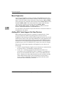
Menu Expansion E-16
Adding SDL Tools Support for New Devices E-16
Example Use of t167 E-18
Use of t167 with the SDL E-18
Add a Second Data Buffer to the t167 Configuration E-20
Issue an INQIRY Command E-22
Issue a Format Command E-23
Issue Reads and Writes to a Disk Device E-24
Use of t167 with the NCR Firmware E-28
Initialize the NCR Firmware Interface E-28
Send SCSI INQUIRY to the Device E-29
Mode Sense Parameters E-32
Issue a Read Command to the Device E-34
List of Figures
Firmware/User Interaction Block Diagram 2-3
Debug Trace Memory Structure 5-3
Directory Structure: bin, src, and lib Files A-2
Directory Structure: Include Files and SIOP Firmware A-2
Directory Structure: sdl Files (sheet 1 of 2) A-3
Directory Structure: sdl Files (sheet 2 of 2) A-4
t167 Submenus and Functions E-2
List of Tables
C Call Interface 3-1
68K Assembler Interface 3-2
88K Assembler Interface 3-2
Firmware Display Frame Map 5-10
Firmware Display Data Map Key 5-11
Typical NCR 53C710 Local Bus Usage for SCSI Data Transfers 5-16
Command Structure B-2
Command Control Bit DeÞnitions B-3
Example Scatter/Gather List B-17
SIOP Clock Rates for VMEmodules B-19
Snoop Control Modes B-19
Debug Logging Initialization Values Structure B-23
SDL Direct Access Commands E-11
SDL Supported Sequential Access Commands E-12
Template Files E-17
xiii
xiv
INTRODUCTION
1
General Information
This chapter explains what SCSI is and what the SBC SCSI Software does to
support SCSI-related hardware on selected Single Board Computers (SBCs). It
also explains the meanings conveyed by the variety of fonts and special text
symbols found throughout this manual. Most importantly, it assists in finding
desirable information on these pages and elsewhere.
N otes
This userÕs manual documents the SBC SCSI Software
Release 1.1. It does not necessarily apply to the release
superceded, which was known as the MVME167/187 SCSI
Software R10V1.
Throughout this manual, the term Single Board Computer
(SBC) refers to any of the MVME162/162LX/166/167/187/197
series of CPU boards.
Organization of This Manual
Here are some short descriptions of the remaining chapters in this manual:
❏ Chapter 2 provides an overall perspective of the core of the SBC SCSI
Software, which is referred to as the SCSI I/O Processor (SIOP) Firmware
(or just Firmware).
❏ Chapter 3 details the programming interface used to invoke the Firmware.
❏ Chapter 4 explains the special tools (NCR Build Tools) used to build the
Firmware from source and how it must be prepared for its run-time
environment.
❏ Chapter 5 covers additional special topics such as the debug logging
facility and certain run-time considerations.
❏ Appendix A maps out the directory structure of the SBC SCSI Software
release media.
❏ Appendix B specifies the data structures used to communicate with the
SIOP Firmware via its programming interface.
❏ Appendix C describes the external routines which must be provided, with
C-language interfaces, in order to compile and use the Firmware.
❏ Appendix D catalogs the FirmwareÕs run-time returned error conditions.
❏ Appendix E documents a demo (test) program which illustrates the use of
the SBC SCSI Software and can be used to verify its functionality.
❏ The Glossary explains terminology often used when discussing the SBC
SCSI Software.
SBCSCSI/D11-1
1
Introduction
Conventions
The conventions used in this document are:
bold
for user input that you type just as it appears; also used for
commands, options and arguments to commands, and names
of programs, directories, and files.
italic
for names of variables to which you assign values; also used
for comments in screen displays and examples.
fixed font
for system output (e.g., screen displays, reports), examples,
and system prompts.
|
to separate two or more items and indicate that a choice is to
be made; only one of the items separated by this symbol
should be selected.
[]
to enclose an item that is optional.
{}
to enclose an optional symbol.
...
to repeat the previous argument.
0x
or
1-2
$
specifies a hexadecimal character. Unless otherwise specified,
all address references are in hexadecimal throughout this
manual.
<CR>
the single key you press that performs the return function.
Single Board Computers SCSI Software UserÕs Manual
Related Documentation
Related Documentation
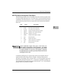
The publications are applicable to the SBCs and may provide additional helpful information pertinent to the use of the SCSI Software. If not shipped with
this product, they may be purchased by contacting your local Motorola sales
office. Non-Motorola documents may be obtained from the sources listed.
Document Title
SBC SCSI Software Release 1.1 Software Release Guide
Motorola
Part Number
SBCSCSI/S1
MVME162 Embedded Controller ProgrammerÕs Reference Guide MVME162PG
MVME162LX Embedded Controller ProgrammerÕs Reference
Guide
MVME162LXPG
MVME166/MVME167/MVME187 Single Board Computers
Programmer's Reference Guide
MVME187PG
MVME197LE, MVME197DP, and MVME197SP Single Board
Computers Programmer's Reference Guide
MVME197PG
MVME162Bug Debugging Package User's Manual
MVME162BUG
MVME167Bug Debugging Package User's Manual
MVME167BUG
Debugging Package for Motorola 68K CISC CPUs UserÕs Manual 68KBUG
MVME187Bug Debugging Package User's Manual
MVME187BUG
Debugging Package for Motorola 88K RISC CPUs UserÕs Manual 88KBUG
MVME197Bug Debugging Package User's Manual
MVME197BUG
MVME162 Embedded Controller UserÕs Manual
MVME162
MVME162LX Embedded Controller UserÕs Manual
MVME162LX
MVME166 Single Board Computer UserÕs Manual
MVME166
MVME167 Single Board Computer User's Manual
MVME167
MVME187 RISC Single Board Computer User's Manual
MVME187
MVME197LE Single Board Computer UserÕs Manual
MVME197LE
N ote
SBCSCSI/D1
Although not shown in the above list, each Motorola
Computer Group manual publication number is suffixed
with characters which represent the revision level of the
document, such as "/D2" (the second revision of a manual);
a supplement bears the same number as a manual but has a
suffix such as "/D2A1" (the first supplement to the manual).
1-3
1
1
Introduction
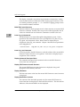
The following publications are available from the sources indicated.
ANSI Small Computer System Interface-2 (SCSI-2), Draft Document X3.131198X, Revision 10c; Global Engineering Documents, P.O. Box 19539, Irvine,
CA 92714.
NCR 53C710 SCSI I/O Processor Data Manual, document #NCR53C710DM;
NCR Corporation, Microelectronics Products Division, Colorado Springs, CO.
NCR 53C710 SCSI I/O Processor ProgrammerÕs Guide, document
#NCR53C710PG; NCR Corporation, Microelectronics Products Division,
Colorado Springs, CO.
Definition of SCSI
According to the SCSI-2 specification,
"SCSI is a local I/O bus that can be operated over a wide range of data rates.
The primary objective of the interface is to provide host computers with device
independence within a class of devices. Thus, different disk drives, tape
drives, printers, optical media drives, and other devices can be added to the
host computers without requiring modifications to generic system hardware
or software. Provision is made for the addition of special features and
functions through the use of vendor unique fields and codes. Reserved fields
and codes are provided for future standardization."
General Description of the SCSI Software
The SCSI Software, or Firmware, for the Single Board Computers (SBCs)
provides comprehensive access to the SCSI bus. It consists of Motorola
Processor (MPU) code and NCR SCSI SCRIPTS code (SCRIPTS) used to
control the NCR 53C710 SCSI I/O Processor (SIOP). The SIOP provides the
actual physical connection to the SCSI bus.
The SCRIPTS are instructions executed by the SIOP which control the specific
operations and functionality of the SIOP. The MPU code formats command
control information in a manner compatible to the SCRIPTS. It also handles
situations where the SIOP or SCRIPTS cannot perform the required function.
From an application viewpoint, the SCSI Software can be interconnected with
the application in order to provide access to the SCSI bus. SIOP programming
is not required in order to create the interconnection. The SCSI Software
allows access to the SCSI bus in conformance with SCSI bus protocols and can
be linked into the final application to create the connection to the SCSI bus.
Typically, an application specific device driver is used to interface application
code with the SCSI Software.
1-4
Single Board Computers SCSI Software UserÕs Manual
General Description of the SCSI Software
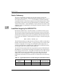
SIOP Firmware
The SIOP Firmware provides these unique features and facilities:
❏
Handles all aspects of SCSI protocol conformance.
❏
No firmware intelligence is imposed on the command requests issued to
peripherals.
❏
Internally enqueues all command requests, in a linked list, until they can
be dispatched to the SCSI bus; therefore, an unlimited number of
command requests can be issued to the Firmware before status for any of
them is received by the user.
❏
Executes in either polled mode or interrupt mode. Polled mode operates
without interrupts and returns from a command after the command
completes.
❏
Provides Target level access (AVAILABLE ONLY IN A FUTURE
RELEASE).
❏
The SIOP executes independently of the Motorola Processor thus reducing
the MPU overhead associated with SCSI accesses.
SBCSCSI/D1
1-5
1
1
Introduction
1-6
Single Board Computers SCSI Software UserÕs Manual
OVERVIEW
2
Introduction
The following chapter is an introduction to the workings of the SIOP Firmware
which is used to control the SCSI port on the SBCs. It is recommended that the
reader have a working knowledge of SCSI.
A Basic View of the SIOP Firmware
The Firmware consists of the Motorola Microprocessor (MPU) code and the
NCR SCSI SCRIPTS code (SCRIPTS) which work together to control the NCR
53C710 SCSI I/O Processor (SIOP).
The MPU code provides the user interface to the SCSI bus. In addition, it
translates user command requests into a format executable by the SCRIPTS,
manages SIOP operating parameters, handles SIOP interrupt conditions,
manages internal command request queues, and returns status to the user.
The MPU code initiates user command requests to the SCSI bus by invoking
the SCRIPTS.
All of the MPU code is written in "C". The interfaces to the Firmware shown
in Chapter 3 are based on the "C" syntax. In addition, "C" syntax is used
throughout this manual for data structures, examples, etc. For the
convenience of assembly language users, Tables 3-2 and 3-3 show the
assembly language interface.
The SCRIPTS, which are instructions executed by the SIOP, control the
functional flow of the SIOP (i.e., transition of SCSI data and control lines). The
SCRIPTS manage the physical thread of each SCSI command request by using
the processed information provided by the MPU code to drive the SIOP.
The SIOP handles the hardware interface to the SCSI bus. The SIOP operates
in a manner which conforms to the physical requirements of the SCSI
specification.
SBCSCSI/D12-1
Overview
2
Firmware Interface
The SIOP Firmware has several externally accessible routines, or entry points,
which may be called by the user to initiate Firmware action. The following is
a brief summary of these routines.
2-2
siop_init()
This routine is for Firmware initialization. The user calls this
entry point to provide the Firmware with memory resources
and basic SIOP operating parameters and to allow the
Firmware to perform required initialization.
siop_cmd()
This routine is for Firmware command requests. The user
calls this entry point to send command structures (siop_struc)
to the Firmware. These commands can be used to either
configure the Firmware or initiate SCSI bus activity. This is
the primary entry point for SCSI bus accesses.
siop_int()
This routine is for SIOP interrupt handling. The user calls this
entry point to allow the Firmware to process interrupts
generated by the SIOP. This entry point must be called at or
above the interrupt level of the SIOP to protect critical code
regions.
sdt_tinit()
This routine is for Firmware debug logging initialization. The
user calls this entry point to enable the debug logger and
provide it with memory resources.
sdt_alloc()
This routine is for debug logging. If debug logging has been
enabled, this entry point is called to get the next block of
memory to be used for debug logging.
sfw_getrev()
The sfw_getrev() entry point provides a release ID string that
identifies the Firmware. The calling application provides a
pointer to MPU-writable memory and the number of bytes
available there.
Single Board Computers SCSI Software UserÕs Manual
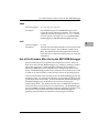
Division of Functional Responsibilities
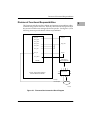
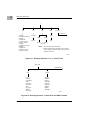
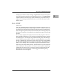
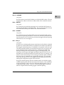
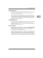
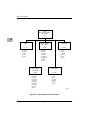
Division of Functional Responsibilities
2
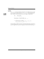
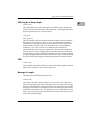
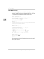
The Firmware and the user have definite and separate responsibilities when
communicating with SCSI devices. Basically, the Firmware manages the SCSI
bus protocol while the user manages the device specifics. (See Figure 2-1.) The
following sections provide details of these responsibilities.
dev_init
siop_init
dev_open
dev_close
siop_cmd
dev_read
dev_write
dev_cntrl
siop_int
dev_intr
dev_status
NCR 53C710
SCSI FIRMWARE
DRIVER
NCR 53C710
TYPICAL APPLICATION-SPECIFIC
DEVICE DRIVER SOFTWARE
interrupt
via PCCchip2
SCSI BUS
1178 9308
Figure 2-1. Firmware/User Interaction Block Diagram
SBCSCSI/D1
2-3
Overview
2
Primary Functions of the Firmware
The Firmware is designed to manage the SCSI bus protocol when interfacing
to a device on the SCSI bus. The Firmware operates independently of any
specific knowledge of devices on the SCSI bus.
The Firmware handles the following aspects of SCSI protocol.
❏
Interpret Received Messages
The Firmware automatically receives and processes the messages received
from target devices.
❏
Send Required/Response Messages
The Firmware generates and sends any required messages, such as
identify, during the course of command processing. The Firmware also
generates and sends messages in response to received messages (e.g.,
synchronous data transfer request message exchange).
❏
Phase Transition Handling
The Firmware automatically handles all phase transitions that occur
during the normal course of interfacing to a SCSI device.
For example, the Firmware transitions through the following bus phases
to execute a single SCSI read command to a disk drive: ARBITRATION,
SELECTION (WITH ATTENTION), MESSAGE (identify), COMMAND,
DATA-IN, STATUS, MESSAGE (command complete), and BUS FREE. In
addition to this minimal set of phase transitions, the device may
disconnect and reconnect several times during the DATA-IN phase. The
Firmware handles each of these phase changes without direct intervention
from the user.
❏
Multi-Threaded Command Management
The Firmware manages multiple threading of commands to the SCSI bus.
SCSI protocol allows for all devices attached to the bus to have
simultaneously outstanding commands. The logical and physical thread
management used to facilitate this multiple threading is handled by the
Firmware and is transparent to the user.
❏
Device Queue Management
The Firmware provides a command queue management scheme that
allows the user to send an unlimited number of command requests to a
device before receiving status for any of them.
2-4
Single Board Computers SCSI Software UserÕs Manual
Division of Functional Responsibilities
❏
Error Recovery
2
The Firmware supports only minimal error recovery. When an error
condition is detected, the Firmware attempts to get the physically
threaded device off the SCSI bus so the bus is free to send command
requests to other SCSI devices or subsequent commands to the same
device.
Primary Functions Required of the User
The following duties are required of a user when interfacing to the Firmware.
❏
Device Configuration Management
The Firmware does not contain device specific knowledge such as device
configuration parameters (i.e., block size). It is the responsibility of the
user to maintain and manage this device specific knowledge.
❏
Resource Allocation
The Firmware does not contain any static data areas; therefore, the user
must provide all of the memory resources for the Firmware. The
Firmware maintains independence from the specific operating system
environment interfacing to it, with respect to memory mapping and cache
management, by requiring the user to allocate memory resources.
❏
Status Interpretation
The user is responsible for interpretation of all status returned by the
Firmware. The Firmware is finished with a command and has released all
resources and knowledge concerning the particular command request
when final status has been posted for a specific command structure
(siop_struc). At this point it is left to the user to determine what subsequent
action is required to handle the returned status. Refer to Appendix D in
this document for a detailed discussion of returned status codes.
❏
User Supplied Routines
The user is responsible for supplying routines which are invoked by the
Firmware. Two of these routines, splhi() and splx(), need to be globally
defined so the Firmware can raise and the lower the interrupt mask when
it is necessary to protect a section of code. A return status routine, which is
specific to the user, is called by the Firmware to notify the user of the
completion of command requests. A pointer to this return status routine
must be installed in every command structure (siop_struc) processed by
the Firmware. Refer to Appendix C.
SBCSCSI/D1
2-5
Overview
2
Functional Overview
The following sections describe the functional attributes of the Firmware. A
simplistic description of the flow of a command request through the Firmware
is given. The SIOP interrupts are explained in some detail as are the Firmware
responses to various SCSI messages which may be received.
Command Flow
The basic flow of the Firmware is followed as a command request is executed.
This flow should give the reader an understanding of the interdependence
between the MPU code, SCRIPTS code, and SIOP in executing a user request.
The first user access to the Firmware is through a call to siop_init(). The
parameters passed to this initialization call set the operation mode of the SIOP
and Firmware. Interrupt level, snoop mode, clock speed, and SCSI address are
all parameters which are used to program the hardware. Different software
paths are taken if the interrupt level is 0 (polled mode) as opposed to non-zero
(interrupt mode). The Firmware needs to be initialized only once, but may be
initialized many times as long as there are no outstanding command requests
to the Firmware when siop_init() is called.
After the Firmware has been initialized, the user initiates a command to an
SCSI device by passing a command structure (siop_struc) to the command
entry point, siop_cmd(). Some of the fields in the siop_struc which the user
must initialize for all command requests are command control (cmd_ctrl),
device SCSI address and LUN (addr_ilvl and lun), command descriptor block
(cdb), and return status routine pointer (status_ptr). Once called, the Firmware
MPU code performs minimal management operations to enqueue the
command structure (siop_struc) for execution by the SCRIPTS. Additionally,
the user may not alter any field within the siop_struc until the control of the
structure is returned to the user through the invocation of the return status
routine.
From this point, the functional flow of the Firmware differs depending on
whether the interrupt level is set for polled mode or interrupt mode. The
following sections outline the flow for the separate modes.
Interrupt Mode
After the command structure (siop_struc) is enqueued for execution, the
Firmware returns control of the MPU back to the user. All subsequent
Firmware MPU code processing of the user's command request is initiated
through the Firmware interrupt handler entry point, siop_int(). The user calls
this entry point when an interrupt from the SIOP is detected.
2-6
Single Board Computers SCSI Software UserÕs Manual
Functional Overview
The first interrupt is generated by the SCRIPTS to notify the MPU code that the
SIOP is not busy with any SCSI bus activity. The MPU code dequeues the next
command structure (siop_struc) which is available for execution and initializes
some SCRIPTS control structures. Next, the MPU code invokes the
appropriate SCRIPTS entry point for the command request.
Control of the MPU is returned to the user after the SCRIPTS begin execution.
All SCSI bus activity is handled without MPU interruption except extended
messages (i.e., synchronous data transfer negotiations), disconnects (to save
the state of the physically threaded command request and, possibly, initiate
another command request to the SCSI bus), reselects (to restore the state of the
physically threaded command request), and error conditions. All of these
situations are detected by the SCRIPTS/SIOP and a corresponding interrupt
generated so the MPU code can resolve the issue.
The command request is finished when the device sends a command complete
message and then transitions to the BUS FREE phase. When this sequence of
events occurs, the SCRIPTS generate another interrupt to notify the MPU code
that the command is done. The MPU code updates some fields in the
command structure (siop_struc), updates Firmware queues, and then calls the
user's return status routine. At this point, the siop_struc is back in the control
of the user. The user may immediately call the Firmware through siop_cmd()
to send a new command request; however, it is recommended that the status
in the status.allstat field of the returned siop_struc be checked first to determine
if any immediate recovery actions are needed (i.e., send a SCSI request sense
command to the device) which might preempt the anticipated command
request.
Upon return from the user's return status routine, the MPU code enqueues the
next available command request for the device which just completed a request.
Finally, the Firmware initiates another command request to the SCSI bus if a
command structure (siop_struc) is available for execution.
Polled Mode
After the command structure (siop_struc) is enqueued, the Firmware calls
siop_int() where the MPU code waits for the command request to complete.
The MPU code resolves intermediate interrupt conditions for the command
request until the command complete interrupt is generated. These
intermediate interrupt conditions are the same as in interrupt mode and
consist of, but are not limited to, extended messages (i.e., synchronous data
transfer negotiations), disconnects (to save the state of the physically threaded
command request), reselects (to restore the state of the physically threaded
command request), and error conditions.
SBCSCSI/D1
2-7
2
Overview
After the command request completes, the MPU code updates some fields in
the command structure (siop_struc), updates Firmware queues, and then calls
the user's return status routine. At this point, the siop_struc is back in the
control of the user. The user may immediately call the Firmware through
siop_cmd() to send a new command request; however, it is recommended that
the user wait until the Firmware returns control of the MPU via the
siop_cmd() return before sending any more command requests. If the user
calls siop_cmd() each time the return status routine is invoked then the stack
eventually overflows. This happens because the Firmware will not have
returned (unstacked) from any of the calls to siop_cmd().
2
Upon return from the user's return status routine, control of the MPU is
returned to the user. The user should now check the status in the status.allstat
field of the command structure (siop_struc) to determine if any recovery
actions are needed.
Interrupt Mechanism
Interrupts from the SIOP are generated in response to various hardware
conditions or are programmed interrupts generated by the SCRIPTS INT
instruction. The SIOP halts SCRIPTS execution whenever an interrupt occurs.
The following is the list of SIOP interrupts.
SCSI Bus Reset
This interrupt is generated when the SIOP detects a SCSI bus
reset. The Firmware terminates all outstanding commands
and returns status for each.
Phase Mismatch
This interrupt is generated when a target changes SCSI phases
before the SIOP data counter register has exhausted its count.
This interrupt occurs when an intermediate disconnect is
pending or a data underrun has occurred.
Selection Timeout
This interrupt is generated when a device at a selected SCSI
address fails to respond within 250 milliseconds after the start
of the SELECTION phase.
Unexpected Disconnect
This interrupt is generated when a target device unexpectedly
transitions to the BUS FREE phase. The Firmware determines
if the disconnect resulted from an intentional action initiated
by the Firmware (i.e., device reset message).
2-8
Single Board Computers SCSI Software UserÕs Manual
Functional Overview
SCSI Gross Error
This interrupt is generated when the SIOP detects an illegal
condition in the SIOP bus control logic (e.g., an overflow of
the SCSI FIFO) or and illegal condition on the SCSI bus (e.g.,
a phase change with an outstanding synchronous offset). The
Firmware hangs if this interrupt occurs.
INT Instruction
This is the SCRIPTS programmed interrupt invoked by the
INT instruction. Programmed interrupts cause the MPU code
to handle situations which the SCRIPTS or SIOP cannot.
Illegal Instruction
This interrupt is generated when the SIOP attempts to execute
an illegal SCRIPTS instruction. Several different situations
can produce an illegal SCRIPTS instruction. The Firmware
determines the specific reason for the illegal instruction. The
Firmware gets the current target off the bus before
terminating the command and returning status to the user.
These are some of the reasons for an illegal instruction.
Bus Fault
SBCSCSI/D1
1.
The NCR SCRIPTS compiler generated the wrong opcode
for a SCRIPTS instruction forcing the SIOP to execute an
illegal opcode.
2.
The memory where the SCRIPTS reside has been
corrupted. This results in the SIOP executing an illegal
opcode.
3.
The SIOP attempts to execute a SCRIPTS instruction
which is non-longword (four-byte) aligned. All SCRIPTS
must be aligned to byte boundaries that are integer
multiples of 4.
4.
The SIOP attempts to transfer information but has been
supplied with a transfer count of zero. This could occur if
the user built an siop_struc to execute a SCSI read but
initialized the data_count Þeld to zero.
This interrupt is generated whenever the SIOP receives a bus
error in response to a local bus access. Action by the
Firmware is dependent upon the current phase of the SCSI
bus.
2-9
2
Overview
Single Step
2
This interrupt is generated only in a special diagnostic mode
enabled by recompiling the Firmware source code. If enabled,
the SIOP generates an interrupt after the successful execution
of each SCRIPTS instruction.
Message Handling
This section deals with the messages that may be received by the Firmware
and the associated Firmware response.
CMD Complete
A SCRIPTS instruction clears the SCSI ACK signal to
complete the MSG-IN phase and then waits for the BUS FREE
phase. A command complete INT instruction interrupt is
then generated.
Save Data Pointers
A SCRIPTS instruction clears the SCSI ACK signal to
complete the MSG-IN phase and then waits for an expected
disconnect message. If a MSG-IN phase does not follow
current message phase then a protocol violation INT
instruction interrupt is generated.
Restore Data Pointers
A SCRIPTS instruction clears the SCSI ACK signal to
complete the MSG-IN phase and then the SCRIPTS transition
to the next phase dictated by the target.
Disconnect
A SCRIPTS instruction clears the SCSI ACK signal to
complete the MSG-IN phase and then waits for the BUS FREE
phase. A disconnect INT instruction interrupt is then
generated.
Message Reject
A message reject INT instruction interrupt is generated. This
holds the bus in the MSG-IN phase while the Firmware
determines which message was rejected by the target. When
the MPU code resolves the rejected message issue, it restarts
the SCRIPTS at an instruction which clears the SCSI ACK
signal to complete the MSG-IN phase.
2-10
Single Board Computers SCSI Software UserÕs Manual
Functional Overview
Linked CMD Complete
A linked command complete INT instruction interrupt is
generated. This holds the bus in the MSG-IN phase while the
Firmware sets up data structures for the next linked
command. The MPU code restarts the SCRIPTS at an
instruction which clears the SCSI ACK signal to complete the
MSG-IN phase and then waits for the COMMAND phase.
Extended Message
A SCRIPTS instruction clears the SCSI ACK signal to accept
the message byte and then the rest of the message bytes are
received. ACK is not negated for the last message byte.
Instead, an extended message INT instruction interrupt is
generated. The MPU code copies the entire message into the
MSG-IN buffer and then restarts the SCRIPTS at an
instruction which clears the SCSI ACK signal to complete the
MSG-IN phase.
If the extended message was a synchronous data transfer
request, then the Firmware determines the next course of
action. If the received message was a response to a
synchronous data transfer request message, the Firmware
logs the acceptable rate and offset. If the message was
unsolicited, then the Firmware builds a response message
with a rate and offset which is mutually acceptable, and then
restarts the SCRIPTS at an instruction which asserts ATN
before it clears ACK. The assertion of ATN tells the target that
the SIOP has a message (out) ready to transmit in response to
the last message (in).
SBCSCSI/D1
2-11
2
Overview
2
2-12
Single Board Computers SCSI Software UserÕs Manual
FIRMWARE INTERFACE
3
Introduction
This chapter defines the interface to the SIOP Firmware. The entry points,
input parameters, and return parameters are also described in this chapter.
For ease of documentation, the following typedefs are used within this section:
typedef unsigned char UCHAR;
/* 8 bit unsigned integer */ typedef
unsigned short USHORT; /* 16 bit unsigned integer */ typedef unsigned
int UINT;
/* 32 bit unsigned integer */
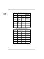
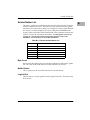
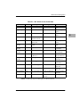
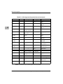
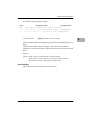
Tables 3-1, 3-2, and 3-3 contain a summary of the entry points and parameters
for the SIOP Firmware.
Table 3-1. C Call Interface
Name
Output
Parameters
Input Parameters
siop_init
init_vals
siopdatap
status
siop_cmd
siop_struc
siopdatap
void (status via
status return routine)
siop_int
siopdatap
sdt_tinit
sdt_tvalue
sdt_alloc
siopdatap
sfw_getrev
string_buffer
SBCSCSI/D13-1
void
siopdatap
void
max_size
bytes available
&trace_entry
Firmware Interface
Table 3-2. 68K Assembler Interface
3
Name
Input Registers
Output
Registers
siop_init
init_vals
4 (A7)
siopdatap
8 (A7)
status
D0
siop_cmd
siop_struc
(A7)
siopdatap
8 (A7)
status via status
return routine
siop_int
siopdatap
4 (A7)
sdt_tinit
sdt_tvalue
4 (A7)
sdt_alloc
siopdatap
4 (A7)
sfw_getrev
string_buffer
4 (A7)
siopdatap
8 (A7)
&trace_entry
A0
max_size
8(A7)
bytes available
D0
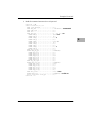
Table 3-3. 88K Assembler Interface
Name
3-2
Input Registers
Output
Registers
siop_init
init_vals
r2
siopdatap status
r3
r2
siop_cmd
siop_struc
r2
siopdatap status via status
r3
return routine
siop_int
siopdatap
r2
sdt_tinit
sdt_tvalue
r2
sdt_alloc
siopdatap
r2
sfw_getrev
string_buffer
r2
siopdatap
r3
&trace_entry
r2
max_size
r3
bytes available
r2
Single Board Computers SCSI Software UserÕs Manual
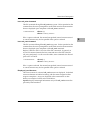
siop_init()
siop_init()
NAME
siop_init ÑInitialize the SIOP Firmware
3
SYNOPSIS
#include
#include
#include
#include
"scsi.h"
"ncr.h"
"ncr710.h"
"scsi_err.h"
/*
/*
/*
/*
SCSI specific definitions */
Firmware structure definitions */
hardware/firmware specific definitions */
error definitions */
UINT siop_init(initvals, siopdatap)
INIT_TYPE_1 *initvals;
/* pointer to a structure which contains init
values (refer to Appendix B) */
struct siopdata *siopdatap;/* SIOP Firmware global data pointer */
DESCRIPTION
The initialization routine initializes the SIOP chip, Firmware structures, and
Firmware flags. It must be called before the siop_cmd and siop_int entry
points. Input to this routine is a pointer to an initialization structure and a
pointer to a global data work area.
The INIT_TYPE_1 initialization structure is defined in the appendix on data
structures (Appendix B). The siopdata area is allocated by your Application,
but its definition is private to the Firmware (see below).
This routine returns status to the caller after initialization is complete.
RETURN VALUE
Status of the Firmware is returned in the least significant byte (LSB) of the
returned value.
SBCSCSI/D1
3-3
Firmware Interface
ERROR CONDITIONS
A successful call to siop_init() must be executed before any other access to the
Firmware can be attempted. All non-zero return codes are fatal and require
the problem to be remedied. The return codes are listed along with an
explanation of their meaning and recommended remedy.
3
SI_GOOD (0x00)
No errors.
SI_BADCLKPAR (0x0A)
A clock speed parameter was supplied that cannot be
interpreted.
If siop_init() is passed an INITPARS/INIT_TYPE_0
structure, this code may also indicate that the MPU clock
(clk_speed) parameter contains ASCII values outside the
range '0' to '9'.
SI_BADPARAM (0x21)
Bad parameter supplied via entry point. Returned when
siop_init() does not recognize the signature of the
initvals structure. Verify that it is a valid structure for the
firmware revision in use.
SI_BADPATCH (0x1E)
The Firmware failed while patching the run-time SCRIPTS
code.
SI_CLK2FAST (0x09)
For INIT_TYPE_1, the sclk_speed initialization parameter is
faster than 75MHz, the highest speed currently supported.
For INIT_TYPE_0/INITVALS, the MPU clk_speed is above
38MHz.
SI_NOSCSIBUS (0x1F)
The SCSI bus was found to be in an illegal state. This may
result from the SIOP being connected to a SCSI bus which is
not correctly powered or terminated.
Refer also to incl/scsi_err.h for defined error values.
3-4
Single Board Computers SCSI Software UserÕs Manual
siop_init()
NOTES
❏
The Firmware needs to be initialized only once but may be initialized
many times as long as there are no outstanding command requests to the
Firmware when siop_init() is called. If a user calls the initialization
routine while commands are outstanding to the Firmware, then
unpredictable results will occur. However, a user may call this module
any number of times before calling the command entry module to
reinitialize the firmware.
❏
The siop data area (siopdata), pointed to by siopdatap, is for use by the
Firmware only and cannot be modified at any time by the caller.The value
of siopdatap passed to siop_init() establishes the value of siopdatap
passed on all subsequent calls to the SIOP other than siop_init(). Only
subsequent calls to siop_init() where a new value of siopdatap is passed
can change the current value. Successive calls to siop_init() with the same
siopdatap has no effect on the current value of siopdatap. The user is
responsible for clearing the siopdata area before calling siop_init() and
must ensure that the siopdata area is cache coherent.
❏
If initialization is called after a call to the command entry point
(siop_cmd()), then all synchronous data transfer information and tagged
command queuing information will be lost. Also refer to the section in
Chapter 5 on Use of the Firmware After Use by the SBC ROM Debugger for
more information.
❏
The user may change the SIOP interrupt level and SIOP SCSI address after
initialization through a CONFIG command to siop_cmd().
❏
The siop data area, pointed to by siopdatap, is for use by the firmware
only and cannot be modified at any time by the caller.
❏
The size of the siop data area pointed to by siopdatap must be of at least
sizeof(struct siopdata) bytes, and must be aligned to a four-byte
boundary.
❏
When using the Firmware Debug Log, the user must call the debug trace
initialization routine sdt_tinit() prior to initializing the firmware.
SBCSCSI/D1
3-5
3
Firmware Interface
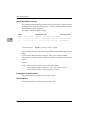
siop_cmd()
NAME
3
siop_cmd ÑSIOP Firmware command call
SYNOPSIS
#include
#include
#include
#include
"scsi.h"
"ncr.h"
"ncr710.h"
"scsi_err.h"
/*
/*
/*
/*
SCSI specific definitions */
firmware structure definitions */
hardware/firmware specific definitions */
error definitions */
void siop_cmd(siop_struc, siopdatap)
struct siop_struc *siop_struc;/* SIOP Firmware command structure
pointer (refer to Appendix B) */
struct siopdata *siopdatap;
/* SIOP Firmware global data pointer */
DESCRIPTION
The function of the command routine is to receive a command structure from
a user and execute the requested operation.
RETURN VALUE
none
ERROR CONDITIONS
Refer to incl/scsi_err.h or Appendix D (Returned Errors) for defined error
values.
Error codes, associated with a command, are posted asynchronously through
the user supplied return status routine found in the command structure.
NOTES
Once a call is made to this routine, the user cannot modify any field within the
command structure associated with the call until the user supplied return
status routine is invoked by the Firmware. The user is responsible for making
sure the memory used for the command structure is cache coherent.
The siop data area, pointed to by siopdatap, is for use by the Firmware only and
cannot be modified at any time by the caller.
3-6
Single Board Computers SCSI Software UserÕs Manual
siop_int()
siop_int()
NAME
siop_int ÑSIOP interrupt handler
3
SYNOPSIS
#include
#include
#include
#include
"scsi.h"
"ncr.h"
"ncr710.h"
"scsi_err.h"
/*
/*
/*
/*
SCSI specific definitions */
firmware structure definitions */
hardware/firmware specific definitions */
error definitions */
void siop_int(siopdatap)
struct siopdata *siopdatap;/* SIOP Firmware global data pointer */
DESCRIPTION
The interrupt handler routine is called by the code which is invoked when the
SIOP interrupt occurs. This routine contains the functions necessary to
execute in the interrupt mode and to recover from intermediate SIOP and
Firmware problems. This is the routine in which the Firmware will idle when
in the polled mode. For initiator and target mode commands, this routine is
responsible for calling the status return routine supplied by the user.
RETURN VALUE
none
ERROR CONDITIONS
none
NOTES
Results are indeterminate if an SIOP interrupt did not occur and this routine
was called by the user.
The siop data area, pointed to by siopdatap, is for use by the Firmware only and
cannot be modified at any time by the caller.
This entry point must be called at or above the interrupt level of the SIOP.
SBCSCSI/D1
3-7
Firmware Interface
sdt_tinit()
NAME
3
sdt_tinit ÑInitialize the SCSI debug trace log
SYNOPSIS
#include "scsi.h"
#include "scsi_dbg.h"
#include "ncr.h"
/* SCSI specific definitions */
/* SCSI debug defines and macros */
/* firmware structure definitions */
void sdt_tinit(sdtptr, siopdatap)
struct sdt_tvalue *sdtptr;
/* pointer to a structure which contains init
values (refer to Appendix B) */
struct siopdata *siopdatap;
/* SIOP Firmware global data pointer */
DESCRIPTION
The function of this routine is to initialize debug tracing. Debug tracing is
useful when problems in the Firmware are encountered and the source of the
problem cannot be detected in any other manner. Trace entries are logged in
the memory range pointed to by the boundary addresses in the sdt_tvalue
structure.
One of the elements in the sdt_tvalue structure is a flag to enable or disable
debug tracing. If the sdt_tvalue structure is located in NVRAM, then enabling
debug tracing is done by simply setting the flag to the proper value prior to
calling this routine. Debug tracing is not normally enabled because the
associated overhead slows the performance of the Firmware. If debug tracing
is enabled, it is recommended to call this routine prior to the call to the
Firmware initialization routine (siop_init()).
RETURN VALUE
none
ERROR CONDITIONS
none
NOTES
This routine may be called any number of times with succeeding calls resetting
the debug log back to the beginning. Calling this routine is allowed prior to
calling the SIOP Firmware initialization (siop_init()) routine.
Performance of the SIOP Firmware is drastically altered when debug tracing
is enabled. For each SIOP command, many debug log entries can be made thus
significantly altering the time it takes to execute the command.
3-8
Single Board Computers SCSI Software UserÕs Manual
sdt_tinit()
Each time the user changes the location of the siopdata structure (changes the
value of siopdatap) for a call to siop_init(), a new call to sdt_tinit with the new
siopdata structure must be made to re-enable debug logging.
For more detailed information concerning use of the debug log, refer to
Chapter 5, Special Topics.
SBCSCSI/D1
3
3-9
Firmware Interface
sdt_alloc()
NAME
3
sdt_alloc ÑAllocate a SCSI debug trace entry
SYNOPSIS
#include "scsi.h"
#include "scsi_dbg.h"
#include "ncr.h"
/* SCSI specific definitions */
/* SCSI debug defines and macros */
/* firmware structure definitions */
struct trace_entry *sdt_alloc(siopdatap)
struct siopdata *siopdatap;
/* SIOP Firmware global data pointer */
DESCRIPTION
The function of this routine is to return a pointer to a debug trace entry. The
returned pointer is the next sequential entry allocated from the block of
memory which was assigned for debug logging with the call to sdt_tinit. The
entry is used to hold information that pertains to the code being traced. Debug
log entry wraparound is possible because the debug log is a circular buffer.
The size of the entry is given by sizeof(struct trace_entry).
RETURN VALUE
Pointer to the trace entry.
ERROR CONDITIONS
none
NOTES
Refer to Chapter 5, Special Topics, for more information.
3-10
Single Board Computers SCSI Software UserÕs Manual
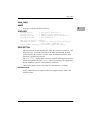
sfw_getrev()
sfw_getrev()
NAME
sfw_getrev Ñ Return Firmware Revision String
3
SYNOPSIS
#include "scsi.h"
#include "ncr.h"
#include "ncr710.h"
#include "scsi_err.h"
/* SCSI specific definitions */
/* firmware structure definitions */
/* hardware/firmware specific definitions */
/* error definitions */
UINT sfw_getrev(string_buffer, max_size);
UCHAR
UINT
*string_buffer; /* revision string is placed here */
max_size;
/* number of bytes available in string_buffer */
DESCRIPTION
The sfw_getrev() entry point provides a release ID string that identifies the
Firmware. The calling application provides a pointer to MPU-writable
memory and the number of bytes available there.
Up to max_size bytes are written into the string_buffer. sfw_getrev()
always returns the number of bytes available. If the number of bytes available
is not greater than max_size, then the return value is just the same as the
number of bytes written. A return value of greater than max_size means that
the given number of bytes are available, but that only max_size will have
been written into the buffer.
RETURN VALUE
The number of bytes of Firmware identification that are available.
ERROR CONDITIONS
none
SBCSCSI/D1
3-11
Firmware Interface
NOTES
A max_size of 32 bytes should be adequate for all available data. If you must
be sure, however, allocate space for string_buffer after determining the
space available. The following shows how one might accomplish this:
3
int
char
avail_size;
*string_buffer;
avail_size = sfw_getrev(NULL, 0);
string_buffer = malloc(avail_size + 1);
if (string_buffer != NULL) {
(void) sfw_getrev(string_buffer, avail_size);
string_buffer[avail_size] = ’\0’;
}
In the preceding example, note that if a null-terminated string is desired, it is
up to the Application to provide enough space and insert the terminating Ô\0Õ.
3-12
Single Board Computers SCSI Software UserÕs Manual
NCR BUILD TOOLS
4
Introduction
The NCR build tools are a set of utilities provided to compile NCR SCSI
SCRIPTS source modules. The utilities provided are the SCRIPTS compiler
and the SCRIPTS preprocessor. The compiler, as written by the NCR
Corporation, is used to compile general purpose SCRIPTS source files into
executable NCR 53C710 machine instructions. The preprocessor, written
specifically for use in the Firmware environment, provides a mechanism
whereby SCRIPTS data references can be changed from the values assigned at
link time to new values defined dynamically at run time as required by the
Firmware.
SCSI SCRIPTS Data Reference Relocation
Because the siopdata data area required by the SIOP Firmware is dynamically
allocated, the references to this data area by SCRIPTS must then be changed
from the link time values through a patching process. This patching is done at
run-time by the siop_init() routine prior to SCRIPTS execution.
The SCRIPTS preprocessor utilities n710p68k and n710p80k are provided to
generate a relocation table used by siop_init() to perform this patch. This table
contains entries pointing to each script array contained in the script source file,
followed by offset values that point to locations within each script array
containing data references that must be patched.
During the Firmware initialization, the siop_init() function walks this
relocation table and patches all locations pointed to by this table to adjust for
the base address of the dynamically allocated siopdata.
Execution of the SCRIPTS preprocessor is required only when the SCRIPTS
source code is recompiled. However, the patching of the SCRIPTS is
performed on each call to siop_init(). Multiple calls to siop_init() perform this
relocation independently of any relocations performed on previous calls to
siop_init().
SBCSCSI/D14-1
NCR Build Tools
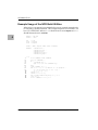
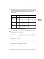
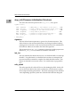
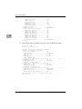
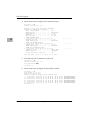
Example Usage of the NCR Build Utilities
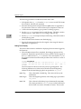
What follows is an extract from a Makefile showing an example .n.o make rule
for compiling a SCRIPTS module. This example is specific to a SYSTEM V/68
host. For a SYSTEM V/88 host, N710P should be set to use n710p80k and N710C
should likewise be set to n710c80k.
TMPDIR = ./tmp_hdrs
INCDIR = ../incl
4
CPP
N710C
N710P
= cc -E
= n710c68k
= n710p68k
PFLAGS = -Um68k -UsysV68 -Um88k -Uunix -I$(INCDIR)
EXTHDRS=
$(INCDIR)/ncr.h \
$(INCDIR)/ncr710.h \
$(INCDIR)/scsi.h \
$(INCDIR)/scsi_err.h \
$(INCDIR)/sfw_cnfg.h
.n.o:
1
2
3
4
5
6
7
8
9
10
11
12
13
14
15
4-2
rm -rf $(TMPDIR); mkdir $(TMPDIR)
@for i in $(EXTHDRS); \
do \
j=‘basename $$i‘; \
grep ’^#.*[^\]$$’ $$i >$(TMPDIR)/$$j; \
done
$(CPP) $(PFLAGS) $*.n | \
sed -e ’s/ */ /g’ -e ’/^# *ident/d’ -e ’/^# *pragma/d’ \
-e ’/^# *[0-9][0-9]*/d’ -e ’s/\[ /\[/g’ \
-e ’s/ \]/\]/g’ > $*.i
$(N710P) $*.i
$(N710C) $*.i -u -o $*.j
sed “/typedef.*ULONG/s/long/int/g” $*.j > $*.c
$(CC) -c $*.c
rm -rf $(TMPDIR) $*.i $*.j $*.c
Single Board Computers SCSI Software UserÕs Manual
Example Usage of the NCR Build Utilities
N ote
With the following explanations, refer to the numbered
columns to the left of the Ò.n.oÓ make rule shown above.
Line(s)
Function
1
Create a directory, TMPDIR, into which Þltered headers will be placed.
2-6
Strip the headers down to only the single-line preprocessor directives.
7
8-10
Use sed to remove blank lines, unknown compiler directives, and other cpp
ejecta which are meaningless to the build utilities (or worse).
11
Invoke the Motorola-supplied SCRIPTS preprocessor.
12
Compile using NCRÕs SCRIPTS compiler.
13
Convert the ULONG typedef from an unsigned long to an unsigned int.
14
Turn the file.c output of the SCRIPTS compiler into an object module.
15
Remove all intermediate Þles and the directory of massaged header Þles.
SBCSCSI/D1
4
Apply the C preprocessor to perform macro substitution on the SCRIPTS
module. Pipe the output to sed for more preprocessing.
4-3
NCR Build Tools
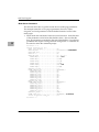
n710p68k (n710p80k)
NAME
n710p68k (n710p80k) ÑPreprocessor for NCR SCSI SCRIPTS files
SYNOPSIS
4
extern
extern
unsigned relocation[];
unsigned script_ptr[];
n710p68k file
DESCRIPTION
The n710p68k (n710p80k) is the NCR SCSI SCRIPTS preprocessor resident on an
MC68xxx (MC88100) host that preprocesses a single SCRIPTS file prior to
compilation by the SCRIPTS compiler. Execution of this utility is required for
any SCRIPTS file compiled for the Firmware environment to enable all
SCRIPTS data references to be made relocatable. This utility takes as input
either a file.n SCRIPTS source file or a file.i output from cpp and generates as
output file.i containing global declarations for a relocation integer array
relocation[] and SCRIPTS pointer integer array script_ptr[]. Source
modules referencing these global arrays MUST make the following declaration
using the EXACT same names and types:
extern unsigned relocation[];
extern unsigned script_ptr[];
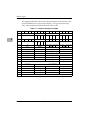
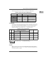
The relocation[] array contains unsigned integer pairs consisting of a token
and associated integer value:
Token
4-4
Token Value
Token Use
Associated Integer Value
SCRIPT_BASE
0x98080000
Script pointer token
Pointer to SCRIPTS
MEM_SIZE
0x0F000001
Script byte size entry
token
Size in bytes of SCRIPTS
DATA_OFFSET
0x88080000
Data offset token
Offset location from
SCRIPTS
CODE_OFFSET
0x80080000
Code offset token
Offset location from
SCRIPTS
TABLE_END
0x60000040
End of relocation table N/A
token
Single Board Computers SCSI Software UserÕs Manual
n710p68k (n710p80k)
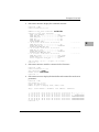
The script_ptr[] array contains pointers to the starting location of each
SCRIPTS declared with a PROC n710c68k (n710c80k) compiler directive. Array
indexes used to access script_ptr[] array elements are global integer
variables generated by the preprocessor and placed in the output file file.i. The
variable name of an array index is formed from the name of the SCRIPTS
array, with the suffix "_idx" appended. The steps in the example below
illustrate how to reference a SCRIPTS pointer for the SCRIPTS array selected.
1.
Declare the external script_ptr[] array:
Example: extern unsigned script_ptr[];
2.
Declare the external array index names:
Example: extern unsigned selected_idx;
Reference the script_ptr[] entry for selected:
3.
Example: script_addr = script_ptr[selected_idx];
RETURN VALUE
If n710p68k (n710p80k) is successful, then 0 is returned. If n710p68k (n710p80k)
is not successful, then a nonzero value is returned and an error message is
printed to stderr.
NOTES
All variables referenced by the SCRIPTS must be contained in a single global
data structure. Furthermore, all references within SCRIPTS instructions to
these variables must be made with the following syntax:
PASS(NCROF(variable))
where the length of the string name for variable cannot exceed 25 characters.
The C macro NCROF is defined as:
#define NCROF(variable) (UINT) &((struct siopdata *) 0)->variable
Here siopdata is the name of the global data structure containing all
relocatable data references. An example SCRIPTS source level instruction
referencing a relocatable variable is:
move memory 1, PASS(NCROF(nopmsg)), PASS(NCROF(q_taginflg))
If the C preprocessor cpp is run prior to the execution of n710p68k (n710p80k),
then it is necessary to prevent the NCROF macro from being expanded until after
n710p68k (n710p80k) has executed.
SBCSCSI/D1
4-5
4
NCR Build Tools
All SCRIPTS instructions must be contained within a single source module.
The identifiers rel_d, rel_c, and NCROF are reserved and may not be used in
the SCRIPTS source code. The SCRIPTS PROC labels relocation and
first_datap are reserved.
SEE ALSO
4
n710c68k (n710c80k)
4-6
Single Board Computers SCSI Software UserÕs Manual
n710c68k (n710c80k)
n710c68k (n710c80k)
NAME
n710c68k (n710c80k) ÑCompiler for NCR SCSI SCRIPTS files
SYNOPSIS
n710c68k file [options] [outfile]
4
DESCRIPTION
The n710c68k (n710c80k) is the NCR SCSI SCRIPTS compiler for the NCR
53C710 SCSI I/O Processor resident on an MC68xxx (MC88100) host that
translates SCRIPTS contained in file to C language integer arrays of NCR
53C710 opcodes and operands. The compiled outfile may then be compiled by
a C language compiler to produce an outfile.o object file. This n710c68k
(n710c80k) compiler does not support directory paths in the specification of
either the file or outfile, requiring file and outfile to reside in the current
directory.
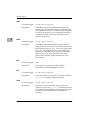
The following options apply:
-e errorfile
This option generates a file where all the error information is
stored. If the -e option is used without specifying errorfile
name, then the errorfile name defaults to file.err.
-l listfile
This option determines if a listfile is generated and if so what
the name of the filename is. If the -l option is given without
specifying a filename, then the filename defaults to file.lis. For
every instruction, the listfile lists an offset from the beginning
of the SCRIPTS, the longword instruction, the longword
address, and the corresponding ASCII source instruction.
Labels appear on a line by themselves as they are encountered
in the SCRIPTS. Also produced is a list of absolute or relative
variables, and their location in the SCRIPTS. This is followed
by a list of labels and label locations that appear in the
SCRIPTS. The location is an offset from the beginning of the
SCRIPTS.
The final list gives the label patches. Label patches are offsets
into the SCRIPTS where a label is referenced. They are called
patches because the absolute address of the labels must be
patched into the SCRIPTS at runtime.
SBCSCSI/D1
4-7
NCR Build Tools
-o outfile
This option determines if a C-compilable data file is generated
and if so what the name of the file is. If the -o is given without
specifying a filename, the output filename defaults to a
file.out.
-u
When this option is set, the definitions INSTRUCTIONS and
PATCHES in the output file is suppressed. This option is
necessary if two or more output files are being linked
together.
-v
This option prints all relevant information about the
compilation process to the screen for the user to view.
-z debugfile
This option generates a file that is necessary if the SCRIPTS
debugger is to be used. If the debugger is used, this is the file
that is loaded to begin the debug process. If the -z option is
given without specifying a debugfile name, then the debugfile
name defaults to file.sod.
4
RETURN VALUE
If n710c68k (n710c80k) is successful then 0 is returned. If n710c68k (n710c80k) is
not successful, then a nonzero value is returned.
NOTES
The PASS() directive allows the string contained within the parentheses to be
ignored by the SCRIPTS compiler and passed directly to the output file. For
example, the statement PASS(#include header.h) results in the line #include
header.h to be placed in the outfile. The string is limited to 32 characters in
length.
The n710c68k (n710c80k) resolves all data references as direct references, which
are then resolved at link time. To generate SCRIPTS that contain data
references that can be relocated at run time, it is necessary to invoke the NCR
preprocessor n710p68k (n710p80k) to generate a run-time relocation table.
The compiler declares all compiled SCRIPTS as C array declarations of type
ULONG. The compiler typedefs ULONG and "unsigned long" in the outfile.
All entries past a PROC directive up to the next PROC directive (or the end of the
source file) are included as elements of the C array produced for that PROC
directive.
SEE ALSO
n710p68k (n710p80k)
4-8
Single Board Computers SCSI Software UserÕs Manual
SPECIAL TOPICS
5
Introduction
This chapter covers topics which most users will not use in the normal course
of SCSI operation. It is provided as a guide for those who wish to exercise the
full functionality of the Firmware.
Firmware Debug Logging
This section describes the operation of the Firmware debug trace mechanism.
Debug tracing is useful when problems are encountered while accessing the
SCSI bus through the Firmware. The debug trace can reveal the source of
many functional discrepancies.
Debug Logging Interface
sdt_tinit()
This routine is for debug logging initialization. The user calls
this entry point to enable the debug logger and provide it with
memory resources.
sdt_alloc()
This routine is for debug logging. If debug logging has been
enabled, this entry point is called to get the next block of
memory to be used for debug logging.
Functional Overview
Implementing a debug trace is composed of three levels of operation. These
levels are the user level setup, code level setup, and trace display.
The user level setup is the first step and involves allocating a block of memory
for the debug log and initializing an sdt_tvalue structure (refer to Appendix
B). The begin and end fields of the structure are initialized to the beginning
and ending address of the allocated memory block. A value of 0x44 (ASCII 'D')
is installed in the flag field to enable debug logging.
The code level setup is the next step. Debug logging becomes enabled when a
call to sdt_tinit() passes in the sdt_tvalue and siopdata structures. sdt_tinit()
checks the flag field in sdt_tvalue for a value of 0x44 (ASCII 'D'). If the flag is
set to this enable value then the routine will set an enable flag in the siopdata
structure. If the flag is not set to this enable value then the routine will clear
the enable flag in the siopdata structure.
SBCSCSI/D15-1
Special Topics
After logging is enabled, a user calls sdt_alloc() to get a pointer to the next entry
to be used for debug logging. A user makes this call from within a section of
code which is suspected to introduce problems or when critical information is
available to be saved in the log.
The final step in debug logging is retrieval and analysis of the logged
information. This is done after a problem has occurred and the user is trying
to determine the source of that problem.
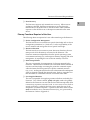
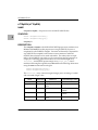
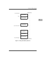
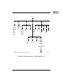
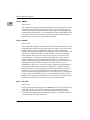
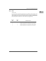
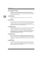
Debug Trace Memory Structure
5
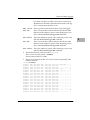
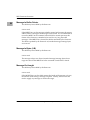
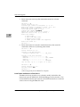
The following figure is a memory diagram of the debug trace log and is
intended to show the order of trace entry allocation.
On the first sdt_alloc() call, the current pointer is equal to the start location
current pointer towards the low end of memory, one frame at a time, until the
special first entry is reached. When the special first entry is reached, a
wraparound condition exists and the current pointer will again be set to
start.
5-2
Single Board Computers SCSI Software UserÕs Manual
Firmware Debug Logging
High Memory
sdt_tvalue.end ->
|
First Log Entry
|
start->
|
Second Log Entry
|
:
|
:
|
:
|
5
|
Current Entry
|
sdt_tvalue.current ->
:
|
:
|
:
|
|
Last Log Entry - 1
|
|
Last Log Entry
|
Special First Entry
sdt_tvalue.begin ->
|
↓
Low Memory
Figure 5-1. Debug Trace Memory Structure
SBCSCSI/D1
5-3
Special Topics
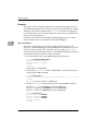
Example
This section shows, through example, how to enable debug logging, how to
record debug information in a trace entry, and how to display the log. A ROM
debugger will be used to initialize the sdt_tvalue structure and display the
log. The information which will be displayed is from currently embedded log
entry points in the Firmware.
Examples shown here use the MVME167 ROM debugger; however, these
same commands can be used with the other ROM debuggers.
5
User Level Setup
This section demonstrates a method for enabling debug logging by the
Firmware. The ROM debugger calls sdt_tinit() before its first access to a local
SCSI device after a board reset. Before this access is made, the sdt_tvalue
structure must be located and initialized. Use the ROM debugger to find and
initialize this structure which is located in NVRAM.
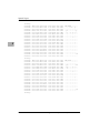
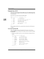
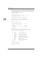
1.
Find the address of the string 'PRVT' using the BS command.
167-Bug>bs fffc0000 fffc2000 'PRVT'
Effective address: FFFC0000
Effective address: FFFC2000
FFFC16F8
167-Bug>
String address = 0xFFFC16F8
2.
The pointer to sdt_tvalue resides at 0xFFFC16F8 + 4. Display this pointer
value using the MD command.
167-Bug>md fffc16f8+4
FFFC16FC FFFC 1758 0000 0000
167-Bug>
0014 0032 5350 4346
...X.......2SPCF
sdt_tvalue structure address = 0xFFFC1758
3.
Initialize sdt_tvalue to the following values using the MM command.
Set the debug_flag to 0x00440000 at location 0xFFFC1758.
Set the begin address to 0x00400000 at location 0xFFFC175C.
Set the end address to 0x00800000 at location 0xFFFC1760.
167-Bug>mm fffc1758;l
FFFC1758 00000000? 00440000
FFFC175C 00000000? 00400000
FFFC1760 00000000? 00800000
FFFC1764 00092691? .
167-Bug>
5-4
Single Board Computers SCSI Software UserÕs Manual
Firmware Debug Logging
4.
Clear the debug trace memory area using the BF command.
167-Bug>bf 400000 800000 0
Effective address: 00400000
Effective address: 007FFFFF
167-Bug>
5.
sdt_tvalue is initialized to enable debug logging but debug logging is not
yet enabled. To enable debug logging and to log some debug trace entries,
execute an IOP command to a local SCSI device.
Code Level Setup
Embedded in the debugger code is a decision to call sdt_tinit() before the first
access to the local SCSI bus after a board reset. Therefore, the debug logging
functionality will have been enabled during the first part of the IOP command
because of the call to sdt_tinit(). Later in the command, a call to siop_cmd()
will have been made to request the Firmware to access a local SCSI device.
Trace entries will have been logged to the debug log during execution of the
Firmware. The following excerpt from the Firmware is where the MPU code
is invoked in response to a command complete interrupt generated by the
SCRIPTS.
UINT sdt_flag = siopdatap->sdt_flag; /* debug logging flag */
/*
* debug log, if enabled
*/
if (sdt_flag == DEBUG_ENABLE)
{
register struct trace_entry *log; /* pointer to debug log entry */
/*
* raise interrupt mask
* get trace memory block
* log block as Firmware entry
* log eyecatcher (source of interrupt)
* log some SIOP register values
* log current command structure
* log command structure (siop_struc)
* restore interrupt mask
*/
s = splhi();
log = (struct trace_entry *)sdt_alloc(siopdatap);
log->eyepicker = SDT_NCR;
log->eyecatcher = SDT_COMP;
save_siop(log, siopdatap);
NCR_LOG(log->data)->cns = *cnsptr;
NCR_LOG(log->data)->cmd = *(cnsptr->curcmd);
splx(s);
}
SBCSCSI/D1
5-5
5
Special Topics
The following procedure was adhered to in the above code.
5
1.
If the global value sdt_flag located in siopdata is set to an ASCII 'D' (0x44)
then continue with the trace operation.
2.
Raise the interrupt mask using the function splhi() (refer to Appendix C).
Save the return value so it can be restored upon completion of the trace.
3.
Call the function sdt_alloc() to get a pointer to a debug log entry.
4.
Set the eyepicker to a unique four byte ASCII string. This Þeld is used to
identify who (i.e., SIOP, driver, etc.) is writing to the trace log.
5.
Set the eyecatcher to a unique four byte ASCII string. This Þeld is used to
identify the log point.
6.
Enter all of the items of interest into the debug log.
7.
Restore the interrupt level back to the original value using the function
splx() (refer to Appendix C).
Debug Trace Display
This section demonstrates a method for displaying the trace entries logged by
the Firmware.
1.
When the IOP command has completed, the debugger prompt will be
displayed. Display the special first trace entry which is always logged at
the begin address of the sdt_tvalue structure. The value used for begin in
this example is taken from the enable procedure above and has a value of
0x400000.
167-Bug>md 400000:10
00400000 0044 0000 0040 0000
00400010 3638 4B3D 0000 0098
167-Bug>
007F FFF0 007F D070
3838 4B3D 0000 004C
.D...@.........p
68K=....88K=...L
The first 32 bytes of the first trace entry are for log management. The
following definitions are referenced to the offset from the beginning
address of the allocated debug log block as specified in sdt_tvalue.
5-6
0x00 - Flag
This is the enable/disable flag. This value will always be
XX44XXXX.
0x04 - Begin
This is the beginning address of the debug log as provided in
sdt_tvalue.
0x08 - End
This is the end of the debug log as determined by sdt_tinit().
The values provided in sdt_tvalue may not have indicated a
block which was sized to X number of entries. There could
Single Board Computers SCSI Software UserÕs Manual
Firmware Debug Logging
have been extra bytes in which a trace entry would not fit.
sdt_alloc() uses this field to determine the bounds of the log
when a wraparound situation occurs.
0x0C - Current This is a pointer to the last trace entry which was logged.
0x10 - 68K
This is an eyecatcher to inform the user that the next field
(68Ksize) is the number to specify when displaying a trace
entry with the 68K ROM debugger MD command.
0x14 - 68Ksize
This is the number to specify when displaying a trace entry
with the 68K ROM debugger MD command.
0x18 - 88K
This is an eyecatcher to inform the user that the next field
(88Ksize) is the number to specify when displaying a trace
entry with the 88K ROM debugger MD command.
0x1C - 88Ksize
This is the number to specify when displaying a trace entry
with the 88K ROM debugger MD command.
2.
Extract the following values from the first_entry.
The current trace entry pointer = 0x7FD070.
The trace entry frame size = 0x98.
3.
Display trace entries from the current trace frame to sequentially older
entries in memory.
167-Bug>md 7fd070:98
007FD070 4E43 5220
007FD080 0000 0000
007FD090 0F00 0000
007FD0A0 FFF4 7036
007FD0B0 0000 6DFC
007FD0C0 0083 A1C8
007FD0D0 0000 1098
007FD0E0 0000 10C0
007FD0F0 0000 1084
007FD100 0000 0000
007FD110 0000 0000
007FD120 0000 0000
007FD130 0103 0100
007FD140 0000 10C0
007FD150 0000 0000
007FD160 0000 0000
007FD170 0000 0000
007FD180 0000 1084
007FD190 0000 0000
SBCSCSI/D1
434F
AE01
FF00
0100
FF83
0000
0000
0000
0008
0000
0000
0100
0000
C001
0000
FF84
0000
0000
0000
4D50
20D4
0000
0000
33CC
0200
0001
0001
000E
60CC
0000
0000
0000
0301
E000
E120
0000
0000
0000
0000
0000
0000
9808
0008
0000
0000
0000
0000
0000
0000
0000
0000
1900
0000
0000
0000
0000
0000
0000
8080
F000
0000
020E
E000
10E7
611C
0000
0000
000A
0007
0000
0000
0000
0000
0000
0001
0000
0000
0000
1200
0000
2100
0000
0000
0001
0000
8004
2800
0000
0000
0000
0000
0000
0000
0000
0000
0000
0000
0000
6DFC
3DE0
000A
0006
0000
0000
000E
0000
10B1
0006
0000
0000
0200
0000
6F64
0000
NCR COMP........
...... .........
................
..p6..........m.
..m...3.....!.=.
................
................
..........a.....
................
......`.........
............(...
................
................
................
................
....... ........
................
..............od
................
5-7
5
Special Topics
167-Bug>
007FD1A0
007FD1B0
007FD1C0
007FD1D0
007FD1E0
007FD1F0
007FD200
007FD210
007FD220
007FD230
007FD240
007FD250
007FD260
007FD270
007FD280
007FD290
007FD2A0
007FD2B0
007FD2C0
5
167-Bug>
007FD2D0
007FD2E0
007FD2F0
007FD300
007FD310
007FD320
007FD330
007FD340
007FD350
007FD360
007FD370
007FD380
007FD390
007FD3A0
007FD3B0
007FD3C0
007FD3D0
007FD3E0
007FD3F0
167-Bug>
5-8
4E43
0000
0F00
FFF4
0000
0083
0000
0000
0000
0000
0000
0000
0103
0000
0000
0000
0000
0000
0000
5220
0000
0000
7021
67EC
98F6
1098
10C0
1084
0000
0000
0000
0100
10C0
0200
0000
0000
1084
0000
5245
AE01
FF00
0100
FF83
0000
0000
0000
0000
0000
0000
0100
0000
C001
0000
FF84
0000
0000
0000
534C
30D4
0000
0800
310A
0200
0001
0001
000E
60CC
0000
0000
0000
0301
E000
E120
0000
0000
0000
8100
4700
0000
9808
000A
0000
0000
0000
0000
0000
0000
0000
0000
1900
0000
0000
0000
0000
0000
0000
8080
F000
0000
400E
E000
10E7
611C
0000
0000
000A
0007
0000
0000
0000
0000
0000
0001
0000
0000
6780
1200
0000
2100
0000
0000
0001
0000
8004
2800
0000
0000
0000
0000
0000
0000
0000
0000
0000
8080
0000
67EC
3DE0
000A
0006
0000
0000
000E
0000
10B1
0006
0000
0000
0000
0000
6F64
0000
NCR RESL........
......0.G...g...
................
..p!..........g.
..g...1...@.!.=.
................
................
..........a.....
................
......`.........
............(...
................
................
................
................
....... ........
................
..............od
................
4E43
0000
0F00
FFF4
0000
0083
0000
0000
0000
0000
0000
0000
0103
0000
0000
0000
0000
0000
0000
5220
0000
0000
7036
6E68
9E46
1098
10C0
1084
0000
0000
0000
0100
10C0
0200
0000
0000
1084
0000
4449
AE01
FF00
BA00
FF83
0000
0000
0000
000A
0000
0000
0100
0000
C001
0000
FF84
0000
0000
0000
5343
20D4
0000
0000
2FDE
0200
0001
0001
000E
60CC
0000
0000
0000
0301
E000
E120
0000
0000
0000
0000
0000
0000
9808
000A
0000
0000
0000
0000
0000
0000
0000
0000
1900
0000
0000
0000
0000
0000
0000
8080
F000
0000
400E
E000
10E7
611C
0000
0000
000A
0007
0000
0000
0000
0000
0000
0001
0000
0000
0000
1200
0000
2100
0000
0000
0001
0000
8004
2800
0000
0000
0000
0000
0000
0000
0000
0000
0000
0404
0000
6E68
3DE0
000A
0006
0000
0000
000E
0000
10B1
0006
0000
0000
0000
0000
6F64
0000
NCR DISC........
...... .........
................
..p6..........nh
..nh../...@.!.=.
...F............
................
..........a.....
................
......`.........
............(...
................
................
................
................
....... ........
................
..............od
................
Single Board Computers SCSI Software UserÕs Manual
Firmware Debug Logging
Firmware Debug Log Map
The following section explains the fields within a Firmware trace entry. The
generic trace entry, as defined in the header file scsi_dbg.h, is:
struct trace_entry {
UINT eyepicker;
UINT eyecatcher;
UCHAR data[LARGE_AMOUNT];
};
All Firmware trace entries will contain an eyepicker entry of NCR that identifies
this as a Firmware trace entry (as opposed to a driver trace frame) and an
eyecatcher label that identifies the unique log point within the Firmware.
The trace data area of each trace entry is mapped according to the following
structure defined in incl/ncr710db.h:
/*
* NCR trace items.
*
* The size of this structure must NEVER get larger than the size of
* the trace_entry.data array[LARGE_AMOUNT] in scsi_dbg.h.
*/
struct ncr_debug {
UINT inst1;
UINT inst2;
UINT inst3;
NCR_SIOP siop;
SIOP_CNS cns;
SIOPCMD cmd;
};
SBCSCSI/D1
/*
/*
/*
/*
/*
/*
1st 32 bits of next SIOP instruction
2nd 32 bits of next SIOP instruction
3rd 32 bits of next SIOP instruction
software model of the chip
copy of the current nexus structure
copy of the siop_struc
*/
*/
*/
*/
*/
*/
5-9
5
Special Topics
The mapping table below shows the relative placement of all structures and
structure elements for a typical screen display. For a given Firmware log
entry, some combination of these elements will be valid.
Table 5-1. Firmware Display Frame Map
Byte
5
0
1
2
0x00
eyepicker
0x10
inst3
3
4
5
6
7
8
A
B
C
D
scid
sbcl
sbdl
inst1
eyecatcher
sien sdid scntl scntl socl
1
0
0x20 sstat2 sstat1 sstat0 dstat
9
dsa
sodl
E
F
sidl
sfbr
inst2
sxfer
ctest3 ctest2 ctest1 ctest0 ctest7 ctest6 ctest5 ctest4
0x30
temp
lcrc ctest istat dfifo
8
0x40
dsp
dsps
dcmd
dnad
scratch3scratch2scratch1scratch0 dcntl
dwt
dien dmode
0x50
adder
datacnt
dataptr
cdblnth
0x60
cdbptr
statlnth
statptr
msgoutlnth
0x70
msgoutptr
msginlnth
msginptr
0x80
curcmd
cmd_cntrl
0x90
sgptr
start
user_defined
cmd_ctrl
0xA0
addr_ilvl
lun
cdb_lgth
cdb[0-3]
0xB0
cdb[4-0xB]
0xC0
siop_id
seqphase[0-7]
msg_in_lgth
msg_in[0-0xB]
msg_in_ptr
msg_out_lgth
0xD0
msg_out_pt
0xE0
data_count
data_ptr
link_ptr
scsi_phase[0-3]
msg_out[0-0xB]
0xF0
scsi_phase[4-7]
status_ptr
status
term_count
0x100
err_addr
qtag
rdyq
waitq
0x110
top
seq
flow
script
0x120
5-10
not used
Single Board Computers SCSI Software UserÕs Manual
Firmware Debug Logging
The mapping table below shows which fields are valid for the given Firmware
debug logging entry point. The entry points are listed according to the
eyecatcher field.
Table 5-2. Firmware Display Data Map Key
Frame Byte
Range
Variable
Group
Valid at
Eyecatcher Entries
Structure
Name
Header
File
0x08 through
0x13
NCR
53C710
opcodes
STEP
instX
ncr710db.h
0x14 through
0x53
SIOP H.W.
Registers
ALL EXCEPT
INIT, CMD
ncr_siop
ncr710.h
0x54 through
0x97
Current
Nexus
Structure
ALL EXCEPT
CMD, QEKO, BRST, STEP,
INIT, XSTO, SIID
siop_cns
ncr.h
0x98 through
0x11F
Command
Structure
ALL EXCEPT
QEKO, BRST, INIT, STEP,
XSTO, SIID, BERR, SGE
siop_struc
ncr.h
5
Firmware Debug Log Entry Descriptions
The following descriptions are listed according to the associated eyecatcher.
BERR
structures logged-
ncr_siop, siop_cns
description-
The SIOP experienced a bus error while accessing the
local bus. The Firmware will attempt to recover from
this condition.
structures logged-
ncr_siop
description-
The SIOP received a SCSI bus reset. All outstanding
command requests to the firmware are returned.
structures logged-
ncr_siop, siop_cns, siop_struc
description-
The SCRIPTS received a command complete message for
the current physically threaded command.
BRST
COMP
SBCSCSI/D1
5-11
Special Topics
DISC
5
structures logged-
ncr_siop, siop_cns, siop_struc
description-
The SCRIPTS received a disconnect message for the
current physically threaded command. The state of the
SCSI command was saved. If another command request
was on the ready queue, it was enqueued for SCRIPTS
command execution, otherwise, the SCRIPTS were
placed in an idle loop.
structures logged-
ncr_siop, siop_cns, siop_struc
description-
The SCRIPTS determined that more data bytes were
being transferred across the SCSI bus than what the user
had indicated in the siop_struc. An error is logged in the
siop_struc. The SCRIPTS will be restarted at an entry
point which will either receive bytes into a bit bucket
(DATA-IN) or write an error pattern to the device
(DATA-OUT) until the target transitions out of the
DATA phase.
structures logged-
none
description-
This log entry only documents that the SIOP
initialization routine siop_init() was called.
structures logged-
ncr_siop, siop_cns, siop_struc
description-
An invalid reselection occurred. A device for which no
siop_struc is available, reselected the SIOP.
structures logged-
ncr_siop, siop_cns, siop_struc
description-
The Firmware SCSI command startup routine was
entered to process an siop_struc. A command structure
was found and dequeued from the ready queue and then
the command was dispatched to the SCRIPTS for
execution.
IDOV
INIT
INT
KICK
5-12
Single Board Computers SCSI Software UserÕs Manual
Firmware Debug Logging
LCMP
structures logged-
ncr_siop, siop_cns, siop_struc
description-
The SCRIPTS received a linked command complete
message for the current physically threaded command.
The Firmware enqueues the next linked siop_struc for
SCRIPTS command execution.
structures logged-
ncr_siop, siop_cns, siop_struc
description-
The SCRIPTS received an message reject message in
response to a message sent to the target for the current
physically threaded command. The Firmware
determines which message was rejected and acts upon
that determination.
structures logged-
ncr_siop, siop_cns, siop_struc
description-
The SIOP detected that the SCSI bus changed phases
before the SIOP counter register exhausted its count for
the previous phase. This situation will occur when a
disconnect is pending or a data underrun has happened.
structures logged-
ncr_siop, siop_cns, siop_struc
description-
The SCRIPTS detected a SCSI protocol violation. An
error is logged in the siop_struc and the SCRIPTS are
restarted at a recovery point.
structures logged-
ncr_siop
description-
The Firmware SCSI command startup routine was
entered to process an siop_struc but no command
structure was found on the ready queue.
MREJ
PMM
PVER
QEKO
SBCSCSI/D1
5-13
5
Special Topics
RESL
structures logged-
ncr_siop, siop_cns, siop_struc
description-
A valid reselection occurred. A device for which a
siop_struc is available, reselected the SIOP. The state of
the command is restored and the SCRIPTS are invoked to
continue execution of the command request.
structures logged-
ncr_siop, siop_cns
description-
The SIOP has experienced a SCSI hardware error. No
recovery action is instituted.
structures logged-
ncr_siop
description-
The SIOP tried to execute an illegal instruction. SCRIPTS
execution was resumed at a recovery point.
structures logged-
inst1, inst2, inst3, ncr_siop
description-
Single step mode has been enabled in the SIOP. Each
instruction executed by the SIOP will be logged.
structures logged-
ncr_siop, siop_cns, siop_struc
description-
The SIOP selection time out timer has expired. The
Firmware returns status to the user.
structures logged-
ncr_siop, siop_cns, siop_struc
description-
The SIOP determined that an unexpected disconnect
occurred. The physically threaded target transitioned to
the BUS FREE phase. The Firmware returns status to the
user.
SGE
5
SIID
STEP
STO
UDC
5-14
Single Board Computers SCSI Software UserÕs Manual
Use of the Firmware After Use by the SBC ROM Debugger
XMSG
structures logged-
ncr_siop, siop_cns, siop_struc
description-
The SCRIPTS received an extended message for the
current physically threaded command. The Firmware
copies the received message into the MESSAGE-IN buffer
and acts upon the message if it was a synchronous data
transfer request or wide data transfer request message.
structures logged-
ncr_siop
description-
The Firmware determined that the external selection time
out timer has expired. This condition is similar to an
STO. The difference is that the internal SIOP time out
timer failed to work and so the SIOP had to be reset and
reinitialized.
XSTO
5
Use of the Firmware After Use by the SBC ROM Debugger
Special considerations are required when using the Firmware to talk to an
SCSI device after the SBC ROM Debugger (e.g., 167Bug or 187Bug) is used to
talk to that same device. ROM Debugger commands such as IOP (I/O
Physical) and BO (Boot) set and expect certain configuration modes on the
device. The ROM Debugger makes every attempt to leave the device in a state
in which it can later be used by other software such as an operating system.
Caution must be used when returning control to the ROM Debugger from the
operating system. For example, the operating system might set a device in the
synchronous data transfer mode. If control is returned to the ROM Debugger,
the ROM Debugger may not be able to access the device (using the
asynchronous mode). The solution for this case is to RESET the SCSI device
on the SCSI bus to return the device to its default state. The ROM Debugger
provides a RESET command and ENV parameters to RESET the SCSI bus. The
user must be aware of these restrictions, and other ROM Debugger to
operating system handoff considerations, when using the Firmware.
SBCSCSI/D1
5-15
Special Topics
Cache Coherency
5
The user is responsible for making sure all of the memory used by the
Firmware is cache coherent. This includes the Firmware data area (siopdata),
the command structure (siop_struct), and all buffers contained within the
command structure. Generally, the proper snoop mode setting (refer to Table
B-5) handles cache coherency for all onboard memory on MotorolaÕs 68040and 88110-based SBCs. On the MVME187, which is based on the 88100, cache
coherency can be accomplished by allocating the Firmware memory in cacheinhibited areas.
Local Bus Usage by the NCR 53C710
Because the NCR 53C710 is a local bus master, it consumes local bus cycles.
The NCR 53C710 uses the local bus to fetch instructions and to transfer data.
The percentage of the local bus bandwidth consumed by SCSI data transfers is
determined by the SCSI data transfer rate (SDTR) and the NCR 53C710 local
bus transfer rate (LBDTR). The bandwidth percentage is calculated using the
equation:
BWP = (SDTR / LBDTR) * 100
The SCSI data transfer rate depends on the SCSI device which is connected to
the SBC and how that device is used. In a typical system, if we assume a disk
transfer is composed of an average seek (16 milliseconds), followed by an
average rotational latency (8 milliseconds), followed by an 8KB data transfer,
the average transfer rate would be about 300KB/sec.
The NCR 53C710 transfers SCSI data using the burst protocol defined by the
MC68040 bus. The NCR 53C710 transfers a maximum of four longwords (16
bytes) during each bus tenure. At 25 MHz, the NCR 53C710 local bus transfer
rate is 57MB/sec for writes and 44MB/sec for reads with parity off and
40MB/sec for reads with parity on. The typical percentage of local bus
bandwidth consumed by SCSI data transfers is summarized in the following
table:
Table 5-3. Typical NCR 53C710 Local Bus Usage for SCSI Data Transfers
5-16
SCSI Data Rate
(MB/sec)
Write
Read
(With Parity Off)
Read
(With Parity On)
0.6
1.1%
1.5%
1.4%
5.0
9.0%
12%
13%
Single Board Computers SCSI Software UserÕs Manual
Target Mode
Target Mode
(THIS INFORMATION WILL BE AVAILABLE ONLY IN A FUTURE
RELEASE.)
5
SBCSCSI/D1
5-17
Special Topics
5
5-18
Single Board Computers SCSI Software UserÕs Manual
DIRECTORY STRUCTURE
A
Miscellaneous files used for the SCSI Software for the compiler and
preprocessor binaries are mentioned in Chapter 4. These files are located
under bin. Other unsupported files are located under src and lib. See Figure
A-1.
The SCSI Software is mostly organized under a single directory, sbc_scsi.
Under this directory are two main subdirectories for the include files and the
SIOP Firmware. See Figure A-2.
These two subdirectories are:
incl/
Contains the SCSI Software-specific include files.
ncr710/
Contains the source files for the SIOP Firmware.
The other subdirectory under sbc_scsi is sdl, which itself has various
subdirectories with several files. See Figure A-3.
All of this directory structure is depicted on the following pages. Note that not
all of the files are supported. Many are for example purposes only and are
released as unsupported software. Refer to the SBC SCSI Software Release 1.1
Software Release Guide, as listed in the Related Documentation section of Chapter
1, for more information.
SBCSCSI/D1A-1
A
Directory Structure
/.
bin/
src/
lib/
task/
sbc_scsi/
continued on
n710c68k
n710c68k.ELF (NOTE 1)
n710c80k
n710c88k.ABI
n710csun3 (NOTE 1)
n710csun4 (NOTE 1)
n710p68k
n710p68k.ELF (NOTE 1)
n710p80k
n710p88k.ABI
n710psun3 (NOTE 1)
n710psun4 (NOTE 1)
ncr710cc/
t167/
88100/
68040/
libsbc.a
libsbc.a
next figure
files
npp710.c
(NOTE 2)
NOTES: 1. THESE FILES ARE NOT SUPPORTED.
2. VMEexec LIBRARIES ARE PROVIDED IN COFF FORMAT.
THEIR CONTENTS ARE BUILT FROM THE SOURCE FILES
SHOWN IN FIGURE A-2.
1179 9311
Figure A-1. Directory Structure: bin, src, and lib Files
sbc_scsi/
continued on
next figure
incl/
ncr.h
ncr710.h
ncr710db.h
scsi.h
scsi_dbg.h
scsi_err.h
sdl.h
sdl_cnfg.h
sdldb.h
sfw_cnfg.h
ncr710/
arel_id.c
intfuncs.c
iscript.n
scsi_dbg.c
scsi_fw.c
siopcmd.c
siopinit.c
siopint.c
siopsupp.c
1180 9311
Figure A-2. Directory Structure: Include Files and SIOP Firmware
A-2
Single Board Computers SCSI Software UserÕs Manual
A
sbc_scsi/
sdl/ (NOTE)
continued on
next sheet
devices/
archive.c
ccsdev.c
cdrom.c
dad_ccs.c
dev_tbl.c
exabyte.c
nodev.c
teacf.c
toshiba.c
wren.c
wren3.c
sdlmgr/
sdlatch.c
sdlcmd.c
sdlstat.c
cdromcmd/
start/
prevent/
fdiskcmd/
common/
attach/
attach/
common/
read/
format/
cdstart.c
cdprevnt.c
toshctl.c
toshejct.c
toshload.c
toshstop.c
toshstrt.c
cdatch.c
attach/
atch_inq.c
frstinq.c
tsturdy.c
write/
scatgat/
teac_sel.c flp_cvrt.c
flpread.c
flpwrite.c
teacatch.c
teachsel.c
flpscat.c
flpfmt.c
getinfo/
gi_sense.c
gi_wp.c
saferead/
postsafe.c
chgintr/
ctrlrst/
inquiry/
passthru/
reqsns/
scsirst/
unsup/
Above directories
are constructed as
follows:
“NAME”/
NOTE: THESE FILES ARE NOT SUPPORTED.
“NAME”.c
1181 9308
Figure A-3. Directory Structure: sdl Files (sheet 1 of 2)
SBCSCSI/D1
A-3
A
Directory Structure
sbc_scsi/
sdl/ (NOTE)
continued from
previous sheet
diskcmd/
attach/
deffmt/
asgnalts/
dadatch.c
dadsel.c
dadsen.c
dkfmtcfg.c
dksen.c
dkstrt.c
postatch.c
wrenatch.c
wrensel.c
reserve/
read/
format/
dkfmtdef.c
dkseldef.c
dksendef.c
readcap/
diskread.c
dkresv.c
dkrdcap.c
dkrtncap.c
scatgat/
write/
saferead/
diskscat.c
dkrsf10b.c
dkrsf6b.c
dkfmt.c
wmfmtcfg.c
diskwrite.c
tapecmd/
common/
read/
saferead/
dkalts.c
scatgat/
write/
space/
allow.c
taperead.c
prevent.c
fread.c
tapescat.c
tapewrit.c
exaspace.c
space.c
attach/
erase/
load/
rdlim/
reserve/
rewind/
wrtfm/
Above directories
are constructed as
follows:
“NAME”/
“NAME”.c
NOTE: THESE FILES ARE NOT SUPPORTED.
1182 9308
Figure A-3. Directory Structure: sdl Files (sheet 2 of 2)
A-4
Single Board Computers SCSI Software UserÕs Manual
SIOP FIRMWARE
STRUCTURES
B
Introduction
This appendix lists all of the structures which are external to or defined by the
SIOP Firmware and which must be provided by the code using the services of
the Firmware.
siop_struc (Command Structure)
The command structure contains all the information necessary to manage a
single call to the SIOP Firmware. This structure is initialized by the user and
allocated to the Firmware when the user makes a command call to the
Firmware. This structure consists of control information, command
information, and various pointers. Each field is defined for the command
mode in which it is used. The INTATR bit, the TARGET bit, and the CONFIG
bit in the Command Control field are mutually exclusive. The Firmware can
operate in only one mode per command. If more than one of these bits are set
in a single command structure then the results are unpredictable. Once this
structure is allocated to the Firmware the user cannot modify any field within
it until the structure is released at status time. The command structure must
be aligned on a four-byte boundary (longword for the CISC MVME162
/166/167; word for the RISC MVME187/197).
Cache coherency for the command structure is the responsibility of the user.
Generally, on all supported SBCs except the MVME187, the proper snoop
mode setting (refer to Table B-5) handles the cache coherency. On the
MVME187, it is suggested that the command structure be allocated in cacheinhibited memory.
SBCSCSI/D1B-1
SIOP Firmware Structures
B
Table B-1. Command Structure
Byte Offset (hex)
00
User ID
04
Command Control
08
Device Address or SIOP Interrupt Level
0C
LUN
10
CDB Length or Queue Depth
14
CDB (bytes 0-3)
18
CDB (bytes 4-7)
1C
CDB (bytes 8-B)
20
Message-In Length
24
Message-In Buffer Pointer
28
Message-In Bytes (0-3)
2C
Message-In Bytes (4-7)
30
Message-In Bytes (8-B)
34
Message-Out Length
38
Message-Out Buffer Pointer
3C
Message-Out Bytes (0-3)
40
Message-Out Bytes (4-7)
44
Message-Out Bytes (8-B)
48
Data Count
4C
Data Pointer or Scatter/Gather List Pointer
50
Link Pointer
54
SCSI Phase Sequence (bytes 0-3)
58
SCSI Phase Sequence (bytes 4-7)
5C
Status Return Function Pointer
60
Status
64
Termination Transfer Byte Count
68
Error Address
6C
SCSI Queue Tag
70-84
B-2
Parameter
Work Area
Single Board Computers SCSI Software UserÕs Manual
siop_struc (Command Structure)
User ID
B
The user ID field is for user command logging. This field is not examined by
the Firmware nor is it altered by the Firmware.
Command Control
The command control field designates the mode in which the Firmware
operates. The three mode bits, INTATR, TARGET, and CONFIG, are mutually
exclusive. The Firmware can operate in only one mode per command request.
In addition to mode control, this field also contains command control
information pertaining to the request contained within the command
structure. The bits within this field are defined below. If a bit is defined for
more than one mode then all modes for which that bit is valid are defined. Bits
that are reserved (rsrvd) should be cleared for future compatibility.
Table B-2. Command Control Bit Definitions
BIT
31
NAME
30
29
INTATR TARGET CONFIG
28
27
26
25
24
rsrvd
rsrvd
rsrvd
rsrvd
rsrvd
BIT
23
22
21
20
19
18
17
16
NAME
rsrvd
rsrvd
rsrvd
rsrvd
rsrvd
PAR
FIRST
DEVRST
14
13
10
9
8
BIT
15
NAME
MIBUF
MOBUF NO_ATN
12
11
rsrvd
rsrvd
SIOPADD SIOPINT SCSIRST
BIT
7
6
5
4
3
2
1
0
NAME
TAG_Q
LINK
rsrvd
S/G
D_PH
R/W
ASYNC
SYNC
Bit 31 -- INTATR
If set, this bit designates the information in the structure to contain control
information in regards to an initiator mode request. Other bits in the
command control field are examined and used as indicated by their initiator
definitions.
SBCSCSI/D1
B-3
SIOP Firmware Structures
B
Bit 30 -- TARGET
If the INTATR bit is not set and the TARGET bit is set then the Firmware
operates in target mode. This bit designates the information in the structure to
contain control information in regards to a target mode request as indicated by
either the T_EXEC or T_WAIT bit in this field. The T_EXEC and T_WAIT bits
are mutually exclusive. Other bits in the command control field are examined
and used as indicated by their target definitions.
Bit 29 -- CONFIG
The configuration control field has the lowest priority of the three mode
control bits which the Firmware examines. If the INTATR bit and the
TARGET bit are cleared and the CONFIG bit is set then the Firmware operates
in the configuration mode. This bit designates the information in the structure
to contain control information in regards to a configuration request. The other
config defined bits are mutually exclusive. Only one configuration mode
request may be executed per command entry call. If this is the only
configuration mode bit set in the command control field then no other
parameters within the command structure are examined and the command
request is handled as a NOP with GOOD status returned.
Bit 18 -- PAR
initiator mode
If set, parity is checked during data transfers. If a parity error is detected a
parity error status is returned but no indication of the byte(s) in error is
returned to the user.
Bit 17 -- FIRST
initiator mode
Setting this bit overrides the normal FIFO ordering of the device queue. The
Firmware places this siop_struc at the head of the device queue to ensure it is
the next command sent to the specified device.
This bit is important in situations where the user wishes to send an
uninterrupted sequence of command requests to a specific device. An
example of this would be a large read, where the number of blocks required
by the user exceeds the block capacity of a 10-byte CDB. The single read must
be broken into a sequence of separate but contiguous commands to the device.
The first read command sent to the Firmware would not set the FIRST bit set;
however, all subsequent command requests in this read sequence would have
this bit set.
B-4
Single Board Computers SCSI Software UserÕs Manual
siop_struc (Command Structure)
Another use of this bit is when sending a request sense command in response
to a CHECK status received for some command to a device. The request sense
command must be sent before any other commands to prevent the CHECK
condition from being cleared before the user can find out the reason for the
CHECK status.
Bit 16 -- DEVRST
initiator mode
If set, the command structure allocated to the Firmware contains a bus device
reset message in the first byte of the message out field. To issue the bus device
reset message to a SCSI device the Firmware selects with ATN asserted and
when the target responds to selection and transitions to the message out phase,
the Firmware responds to that phase by sending the message in the messageout field.
The user must initialize the command structure for this sequence. The user
must install the SCSI address, LUN, message-out length, message-out pointer,
and message byte. (The message-out pointer field can point to the messageout field of the structure if that is where the user installed the bus device reset
message.) Additionally, the user must clear the NO_ATN bit, set the MOBUF
bit, and set the DEVRST bit in the command control field. The DEVRST bit is
used for error checking and is not tested except for unexpected disconnects.
In the case of an unexpected disconnect, if the DEVRST bit is set, the Firmware
resolves the device reset condition. For a device reset condition all pending
commands to the target LUN are returned. Internal synchronous data rate
information is set to asynchronous. Internal tagged command queuing
information is set to non-support.
SBCSCSI/D1
B-5
B
SIOP Firmware Structures
B
Bit 15 -- MIBUF
initiator mode
If set, defines the message-in buffer pointer field to contain a pointer to a buffer
where messages from the target are to be saved. If clear, the messages are
saved in the 12-byte message-in field and the message-in buffer pointer field
is initialized by the Firmware. It is recommended to NOT set the MIBUF in the
command control field for normal operation; this feature of the Firmware is
intended to be used for very long extended messages.
Bit 14 -- MOBUF
initiator mode
If set, defines the message-out buffer pointer field to contain a pointer to a user
initialized buffer where messages to the target are located. The user also must
initialize the message-out length field to the byte count of the message
transfer. The user is responsible for ALL messages to be sent to the target. The
first byte in the buffer must be an identify message. The external message
buffer cannot contain synchronous data transfer request or wide data transfer
request messages. Synchronous data transfer negotiations and wide data
transfer negotiations must be handled by the Firmware. Additionally, if
tagged command queuing is enabled then this bit should not be set because if
the target disconnects and then reselects, the Firmware has no way of
rethreading for this nexus. If clear, the Firmware initializes the message-out
buffer pointer field and the message-out length field. Also the Firmware
generates all necessary message bytes such as identify (if the NO_ATN bit is
cleared), queue tag (if tagged queuing has been enabled in the Firmware),
synchronous data transfer request (if the SYNC or ASYNC bit is set), and wide data
transfer request (if the WIDE16 bit is set). It is recommended to NOT set the
MOBUF in the command control field for normal operation; this feature of the
Firmware is intended to be used for very long extended messages.
Bit 13 -- NO_ATN
initiator mode
If set, Firmware selects the target device without ATN asserted. This bit is set
if the user does not wish for the target device to disconnect during this
command. This bit cannot be used with SCSI linked commands or with
devices that have tagged command queuing enabled. For SCSI bus efficiency,
it is recommended to NOT set this bit.
B-6
Single Board Computers SCSI Software UserÕs Manual
siop_struc (Command Structure)
Bit 10 -- SIOPADD
B
config mode
If set, the Firmware sets the SCSI address at which the SIOP resides. The user
designates the address in the device address field of the command structure.
Bit 9 -- SIOPINT
config mode
If set, the Firmware installs the interrupt level at which the SIOP Firmware
interrupts the MVME167/MVME187 MPU. The user designates the interrupt
level in the SIOP interrupt level field of the command structure.
Bit 8 -- SCSIRST
config mode
If set, the Firmware causes the SCSI bus to be reset and terminated status is
returned for all pending commands. For all LUNs, internal synchronous data
rate information is set to asynchronous and internal tagged command queuing
information is set to non-support.
Bit 7 -- TAG_Q
config mode
If set, the user is informing the initiator mode Firmware that the drive defined
by the device address field and the LUN field has been enabled or disabled for
SCSI tagged command queuing. If enabled the user specifies with a non-zero
value the maximum number of commands the target LUN can queue in the
queue depth field of the command structure. The Firmware handles the
message exchanges that are required for tagged command queuing. The
simple queue tag message is the tagged queuing message the Firmware uses. If
the FIRST bit is set then the Firmware uses the head of queue tag message. The
initiator mode Firmware keeps track of the tags and makes status available to
the user as soon as commands are completed by the target. The user must
insure that the target LUN is in the tagged command queuing mode before
sending this configuration request to the Firmware.
If tagged command queuing has been enabled and the user disables tagged
command queuing then the user must notify the Firmware. This notification
is done by placing a value of zero (0) in the queue depth field for a TAG_Q
configuration mode request. However, all outstanding tagged commands
must be completed before disabling tagged command queuing.
SBCSCSI/D1
B-7
SIOP Firmware Structures
B
Bit 6 -- LINK
initiator mode
If set, command in the CDB has the link bit set. The link field in the command
structure must point to the next command structure to be used. This bit must
be set for linked commands so the Firmware does not flag a linked command
operation as a protocol violation.
Bit 4 -- S/G
initiator mode
If set, scatter/gather is used for data transfers. The user must supply a
scatter/gather list. The pointer to the scatter/gather list is in the Data Pointer
field of the command structure. The scatter/gather list must be aligned to a
four-byte boundary.
Bit 3 -- D_PH
initiator mode
If set, the command contained in the CDB causes a data phase. For example,
test unit ready does not have a data phase associated with it; this bit should be
cleared. A read command has a data phase associated with it; this bit should
be set. A format unit command may or may not have a data phase associated
with it. The bit should be set if a defect list is to be included in the command.
If no defect list or defect list header is to be sent then this bit should be cleared.
Bit 2 -- R/W
initiator mode
If set, data direction is in to the initiator (read). If clear, data direction is out
from the initiator (write). This bit is ignored if the D_PH bit is not set.
Bit 1 -- ASYNC
initiator mode
If set, the Firmware initiates negotiations for asynchronous data transfers.
Normally, this bit is only set to place the SCSI device in a state that is
compatible with the state of the Firmware after a call to the initialization
module. If a synchronous data transfer rate has not been established then the
user should clear this bit to avoid unnecessary negotiations.
B-8
Single Board Computers SCSI Software UserÕs Manual
siop_struc (Command Structure)
Bit 0 -- SYNC
B
initiator mode
If set, the Firmware initiates negotiations for synchronous data transfers. The
SIOP initiates negotiation for the maximum offset it supports and the fastest
period possible. If a synchronous data transfer rate has been established then
the user should clear this bit to avoid unnecessary negotiations.
ASYNC
Bit
SYNC
Bit
0
0
does not initiate negotiations
0
1
initiates negotiations for synchronous data transfers
1
0
initiates negotiations for asynchronous data transfers
1
1
initiates negotiations for synchronous data transfers
SBCSCSI/D1
Firmware Action
B-9
SIOP Firmware Structures
B
Device Address or SIOP Interrupt Level
initiator mode
The user initializes the device address field with the SCSI address of the device
to be accessed. For example, a command for SCSI address 4, LUN 2 would
need a 0x00000004 placed in this field.
config mode
TAG_Q bit setThe user initializes the device address field with the SCSI address of the target
device that supports tagged command queuing. For example, SCSI address 6,
LUN 1 would need a 0x00000006 placed in this field.
SCSIADD bit setThe user initializes this field with the SCSI address that the
MVME167/MVME187 SCSI port (SIOP) is to occupy. For example, if the user
wants the SIOP to occupy address 4 then 0x00000004 would be placed in this
field. This field is not checked for erroneous values. Instead, it is interpreted
as a modulo 8 value; therefore, a hex value of 0xf9 is read as 0x01.
SCSIINT bit setThe user initializes this field to the level (1 through 7) at which the SIOP is to
interrupt the MPU. For polled mode (Firmware does not relinquish processor
until command is complete) this field is cleared (0x00). This field is not
checked for erroneous values. Instead, it is interpreted as a modulo 8 value;
therefore, a hex value of 0x146578 is read as 0x00.
LUN
initiator mode
The user initializes the LUN field with the Logical Unit Number (LUN) of the
target device to be accessed. For example, a command for SCSI address 4,
LUN 2 would need a 0x00000002 placed in this field so the Firmware can
generate the correct identify message needed for selection.
config mode
TAG_Q bit setThe user initializes the LUN field with the logical unit number of the target
device that supports tagged command queuing. For example, SCSI address 0,
LUN 1 would need a 0x00000001 placed in this field.
B-10
Single Board Computers SCSI Software UserÕs Manual
siop_struc (Command Structure)
CDB Length or Queue Depth
B
initiator mode
The CDB length field contains the length of the CDB, in bytes, that the user
wants to be transferred during the command phase. CDB lengths defined by
the SCSI specification are 6, 10, and 12 bytes.
config mode
TAG_Q bit setThe user initializes this field with the maximum number of SCSI commands
the target LUN can queue at a time. A value up to 0xff means the initiator
mode Firmware dispatches up to that many commands to the target device
without waiting for SCSI status to be returned for any of the outstanding
commands. Any value over 0xff is not defined by the current SCSI
specification and a Firmware error is generated. The Firmware interprets a
value of zero (0) to mean untagged queuing and the Firmware control fields
are set to reflect non-support of tagged command queuing. Untagged queuing
is implicitly supported by the Firmware; therefore, a value of zero (0) should
only be used to disable tagged command queuing after it has been enabled.
CDB
initiator mode
The CDB field contains the CDB that is to be transferred during the command
phase on the SCSI bus for this command structure.
Message-In Length
This field may be modified by the Firmware.
initiator mode
The value in this field is used for buffer over-run control. The value in this
field is decremented as the returned message bytes are placed in the MessageIn buffer. If the MIBUF bit is not set then this value is initialized to 12 and the
Message-In Pointer field is initialized to point to the Message-In Bytes buffer
within this command structure. The Firmware receives all messages from the
target. The only messages placed in the buffer (returned to the user), however,
are SCSI extended messages.
SBCSCSI/D1
B-11
SIOP Firmware Structures
B
Message-In Buffer Pointer
This field may be modified by the Firmware.
initiator mode
If the MIBUF bit is set, the message-in buffer pointer field contains the starting
address where a message from the target is to be stored. It is recommended to
not set the MIBUF in the command control field for normal operation; this
feature of the Firmware is intended to be used for very long extended
messages. If the MIBUF bit is cleared, this field is initialized by the Firmware.
This field is updated by the Firmware as (extended message) message bytes
are received.
Message-In Bytes (0-B)
This field may be modified by the Firmware.
initiator mode
The message-in bytes are where (extended message) message bytes from a
target are stored if the MIBUF bit in the command control field is cleared.
Message-Out Length
This field may be modified by the Firmware.
initiator mode
If the MOBUF bit is set, this field contains the length of the message, in bytes,
the initiator sends during a message-out phase. Usually, the user does not
need to supply any messages to send to the target.
B-12
Single Board Computers SCSI Software UserÕs Manual
siop_struc (Command Structure)
Message-Out Buffer Pointer
B
This field may be modified by the Firmware.
initiator mode
If the MOBUF bit is set, the message-out pointer field contains the address
where a message to the target is placed. Normally, the user does not need to
supply any messages to send to the target. It is recommended to not set the
MOBUF bit in the command control field for normal operation; this feature of
the Firmware is intended to be used for very long extended messages. If the
MOBUF bit is cleared, this field is initialized by the Firmware.
Message-Out Bytes (0-B)
This field may be modified by the Firmware.
initiator mode
If the MOBUF bit cleared, the message-out bytes are where messages to a
target are placed.
Data Count
This field may be modified by the Firmware.
initiator mode
The data count field contains the number of bytes to be transferred during a
data phase on the SCSI bus. If no data phase is to be executed then this field
must be set to zero (0x00000000). This value must not exceed 24 bits
(0xFFFFFF or 16,777,215). If the S/G bit is set in the command control field
then this field is ignored.
SBCSCSI/D1
B-13
SIOP Firmware Structures
B
Data Pointer or Scatter/Gather List Pointer
This field may be modified by the Firmware.
initiator mode
The data pointer field contains a pointer to a buffer where data is transferred
to/from. If the S/G bit is set in the command control field then this field
contains a pointer to a scatter/gather list. The scatter/gather list must be
aligned on a four-byte boundary (longword boundary for the CISC
MVME167; word boundary for the RISC MVME187).
Link Pointer
initiator mode
The link pointer field is initialized by the user for linked commands. This field
points to the command structure which contains the linked CDB. The LINK
bit in the command control field in this structure must be set and the link bit
in the CDB must be set.
Status Return Function Pointer
initiator mode
This field contains the starting address of a function that processes a returned
command structure. The Firmware calls this routine as a "C" function and
passes the address of the finished command structure to it.
void (* ret_stat)();
/* define ret_stat as a pointer to a function */
ret_stat = siop_struc->ret_stat; /* init ret_stat with address of rtn */
ret_stat(&siop_struc); /* call routine with command structure as input */
B-14
Single Board Computers SCSI Software UserÕs Manual
siop_struc (Command Structure)
Status
B
initiator mode
The status field contains status concerning the target device, Firmware, and
SCSI bus. The least significant byte in this field contains the status received
from the target during the status phase of the SCSI command. The second least
significant byte in this field contains an error code generated by the Firmware
if a Firmware detected error occurred. This field is initially cleared by the
Firmware when the command structure is first allocated to the Firmware.
config mode
The least significant byte in this field is not used for a config mode request.
The second least significant byte in this field contains an error code generated
by the Firmware if a Firmware detected error occurred. This field is initially
cleared by the Firmware when the command structure is first allocated to the
Firmware.
Termination Transfer Byte Count
initiator mode
The termination transfer count field contains the number of bytes successfully
transferred during a data phase on the SCSI bus. The user should compare this
value with the expected count to verify that the correct number of bytes were
transferred. This field is initially cleared by the Firmware when the command
structure is first allocated to the Firmware.
Error Address
initiator mode
This is the address where an SIOP bus fault or illegal SIOP instruction error
was encountered.
SCSI Queue Tag
initiator mode
This field is used by the Firmware to track queued commands to peripherals
that support SCSI tagged command queuing. Upon command completion this
field contains the queue tag used by the Firmware.
SBCSCSI/D1
B-15
SIOP Firmware Structures
B
Work Area
initiator mode
The work area fields are used by the Firmware to save, change, or amend
device and command dependent parameters and statuses.
B-16
Single Board Computers SCSI Software UserÕs Manual
Scatter/Gather List
Scatter/Gather List
B
The scatter/gather list is initialized by the user and allocated to the Firmware
with the command structure. The Firmware may modify the scatter/gather
list in the case of a disconnect. Below is an example of a scatter/gather list with
two entries. For this example list, the user would place 0x00004000 in the
Scatter/Gather List Pointer (Data Pointer) field of the command structure and
set the S/G bit in the command control field. A scatter/gather list must be
aligned on a four-byte boundary (longword boundary for the CISC
MVME167; word boundary for the RISC MVME187).
Table B-3. Example Scatter/Gather List
Address
Parameter
0x4000
24 bit Byte Count
0x4004
Buffer Pointer
0x4008
24 bit Byte Count
0x400C
Buffer Pointer
0x4010
Logical End (32 bit value = 0)
0x4014
don't care
Byte Count
Byte count is the number of bytes to transfer for this entry of the scatter/gather
list. The value in this field must not exceed 0xFFFFFF (16,777,215).
Buffer Pointer
This is a pointer to the area where the data is to be transferred.
Logical End
The last entry in a scatter/gather list is the logical end of list. This entry must
be all zeroes.
SBCSCSI/D1
B-17
SIOP Firmware Structures
B
siop_init (Firmware Initialization Structure)
This is the data structure passed to the siop_init() entry point.
typedef struct {
UINT signature
UINT intr_lev;
UINT sclk_speed;
UINT snoopmode;
RELC *reloctbl;
UINT *script_ptr;
/*
/*
/*
/*
/*
/*
MASK_INIT_1 | SCSI address of the SIOP */
0x00
level at which SIOP interrupt should occur */0x04
frequency of the SIOP clock (in Hz) */
0x08
snoop mode of processor */
0x0c
pointer to scripts relocation table */
0x10
pointer to script pointer array */
0x14
} INIT_TYPE_1;
signature
The first 32-bit element represents a signature for the entire structure. This
allows firmware data structure definitions to be changed without breaking
existing source or binaries. In the case of the structure used for initialization,
the SCSI host address is encoded in the LSB of the signature.
The signature for an INIT_TYPE_1 structure is a bitwise-or of the preprocessor
define MASK_INIT_1 ('IT1\0') and the SCSI address of the SIOP.
intr_lev
The user initializes this field to the level (1-7) at which the SIOP is to interrupt
the MPU. For polled mode, in which the firmware does not relinquish the
processor until the command is complete, this field should be cleared. This
field is not checked for erroneous values. It is used directly to program the
PCC.
sclk_speed
This is the speed (in Hz) of the SCSI core clock feeding the SIOP. In the NCR
53C710 SIOP Data Manual, this clock is referred to as SCLK and it is used to
derive important timing information. The SCLK rate being fed into the SIOP
varies depending upon the system into which the SIOP has been designed.
B-18
Single Board Computers SCSI Software UserÕs Manual
siop_init (Firmware Initialization Structure)
The following table lists the SCLK rate on Motorola VMEmodules:
B
Table B-4. SIOP Clock Rates for VMEmodules
VMEmodule
MPU Clock
SIOP Clock
MHz
MHz
25
50
50000000 (0x02FAF080)
33
66
66666666 (0x03F940AA)
50
50
50000000 (0x02FAF080)
167
187
167
187
197
Hz
snoopmode
The SIOP has snoop control output lines which are compatible with the snoop
control inputs of the MC68040 and MC88110. The user initializes this field to
the snoop control mode in which the SIOP is to operate. Recommended
settings for the SBCs are indicated with a Ò*Ó in the table below.
Table B-5. Snoop Control Modes
Bit 1
Bit 0
Requested Snoop Operation
Read Access
Write Access
0
0
Inhibit Snooping
Inhibit Snooping
0
1
Supply Dirty Data
and Leave Dirty
Sink Byte/Word/Long Data
1
0
Supply Dirty Data
and Mark Invalid
Invalidate Data
1
1
Reserved (Snoop
Inhibited)
Reserved (Snoop Inhibited)
N ote
MVME162/
166/167/197
MVME187
*
*
In the table above, * = recommended setting.
reloctbl
The user initializes this field to the globally defined value of the relocation
table (extern RELC relocation[]) which is created by the preprocessor
to the NCR SCRIPTS compiler.
SBCSCSI/D1
B-19
SIOP Firmware Structures
B
script_ptr
The user initializes this field to the globally defined value of the SCSI Script
pointer array (extern unsigned script_ptr[]) which is created by the
preprocessor to the NCR SCRIPTS compiler.
B-20
Single Board Computers SCSI Software UserÕs Manual
Initialization Structure (depreciated version)
Initialization Structure (depreciated version)
B
The INITPARS structure is archaic. It is defined here in order to support
compatibility with existing code. Please switch to using its replacement, the
INIT_TYPE_1 structure.
typedef struct {
UINT scsi_addr;
UINT intr_lev;
UINT clk_speed;
UINT snoopmode;
RELC *reloctbl;
UINT *script_ptr;
/*
/*
/*
/*
/*
/*
SCSI address of the SIOP */
Level at which SIOP interrupt will occur */
ASCII representation of MPU clock (x10KHz) */
Snoop mode of processor */
Pointer to scripts relocation table */
Pointer to script pointer array */
0x00
0x04
0x08
0x0c
0x10
0x14
} INIT_TYPE_0, INITPARS;
SCSI Address
The user initializes this field with the SCSI address that the MVME167 or
MVME187 SCSI port (SIOP) is to occupy. For example, if the user wants the
SIOP to occupy address 4 then 0x00000004 would be placed in this field.
In the case of this structure, the signature is defined as 0. This definition,
combined with the assumption that existing source and binaries followed
recommended practice when initializing the scsi_addr parameter, allows the
initialization code to know what it is looking at without breaking existing
applications.
Interrupt Level
Same definition as in the INIT_TYPE_1 structure.
Clock Speed
The user initializes this field to an ASCII value which is equal to the clock
speed of the MPU as expressed as a multiple of 10KHz. For example, if the
clock speed of the MPU was 25MHz then this field should be initialized to
'2500' (0x32353030).
Snoop Mode
Same definition as in the INIT_TYPE_1 structure.
Pointer to Relocation Table
Same definition as in the INIT_TYPE_1 structure.
SBCSCSI/D1
B-21
SIOP Firmware Structures
B
Pointer to Script Pointer Array
Same definition as in the INIT_TYPE_1 structure.
B-22
Single Board Computers SCSI Software UserÕs Manual
sdt_tinit (Debug Logging Initialization Structure)
sdt_tinit (Debug Logging Initialization Structure)
B
Some of the initialization values which are used by the debug logging
initialization routine, sdt_tinit, are contained in a structure. A pointer to this
structure is passed into the initialization routine. The fill bytes in the structure
are unused at the current time and it is recommended to clear these bytes.
Table B-6. Debug Logging Initialization Values Structure
Byte offset (hex)
00
Parameter
Þll
Flag
Þll
04
Beginning Address
08
Ending Address
Þll
Flag
This field is examined for a value of 0x44 (ASCII 'D') to determine if debug
logging is to be enabled. If this field is not 0x44 then an internal debug logging
flag is set to disabled and debug logging initialization is terminated.
Beginning Address
If debug logging is enabled, then this is the beginning address of a block of
memory that has been allocated for debug logging. If this address is greater
than the Ending Address, then debug logging is disabled. If the size of the
block of memory is less than the size of one debug log entry, then debug
logging is disabled.
Ending Address
If debug logging is enabled, then this is the ending address of a block of
memory that has been allocated for debug logging. If this address is smaller
than the Beginning Address, then debug logging is disabled. If the size of the
block of memory is less than the size of one debug log entry, then debug
logging is disabled.
SBCSCSI/D1
B-23
SIOP Firmware Structures
B
B-24
Single Board Computers SCSI Software UserÕs Manual
EXTERNAL ROUTINES
C
Introduction
The SCSI Software requires services to be provided external to the SCSI
Software itself. These services must be provided by the specific application.
There are two global services which must be provided:
splhi
A routine used to mask interrupts from the NCR 53C710 SCSI
chip. This may be a null routine if the specific application of
the SCSI Software uses the software in polled mode (i.e., at
interrupt level 0).
splx
A companion routine to splhi, used to restore interrupts to
the level existing before the corresponding splhi. This may be
a null routine if the specific application of the SCSI Software
uses the software in polled mode (i.e., at interrupt level 0).
Also, a command-specific service must be provided:
ret_stat
A routine called by the Firmware to notify the user that final
status is available for a command request. A pointer to this
routine is supplied in each command structure (siop_struc)
issued to the Firmware.
Firmware for the MVME197 also requires routines to enforce serialized access
to I/O registers:
serialize_memory_access
deserialize_memory_access
When compiling to run on that board (refer to the file incl/sfw_cnfg.h), the
user-supplied routines set/clear the SRM (serialize memory) bit in the 88110 PSR
(processor status register). If one compiled object may be executed on both an
88100 and an 88110, then those routines should verify that the processor is an
88110.
All of the above routines are described further on the following pages.
SBCSCSI/D1C-1
External Routines
splhi
NAME
C
splhi ÑMask interrupts
SYNOPSIS
UINT splhi()
DESCRIPTION
The splhi routine masks interrupts from the NCR 53C710 SCSI chip. This
routine is normally used in conjunction with splx.
Example:
level = splhi();
/* mask interrupts */
/* code that cannot be interrupted goes here */
splx(level);
/* go to previous priority level */
RETURN VALUE
splhi is always successful and returns the previous interrupt priority level.
This value is hardware specific and it is not guaranteed to be in the range 0
through 7.
ERROR CONDITIONS
none
C-2
Single Board Computers SCSI Software UserÕs Manual
splx
splx
NAME
splx ÑRestore Interrupt Priority Level
C
SYNOPSIS
UINT splx(level)
UINT level;
/* previous Interrupt Priority Level */
DESCRIPTION
The splx routine restores the interrupt priority level following a call to splhi.
This function is normally used in conjunction with splhi. level is hardware
specific and is not guaranteed to be in the range 0 through 7.
Example:
level = splhi();
/* mask interrupts */
/* code that cannot be interrupted goes here */
splx(level);
/* go to previous priority level */
RETURN VALUE
none
ERROR CONDITIONS
none
SBCSCSI/D1
C-3
External Routines
ret_stat
NAME
C
ret_stat ÑNotify User of Command Completion
SYNOPSIS
void ret_stat(cmd)
struct siop_struc *cmd;
/* completed command structure */
DESCRIPTION
The ret_stat routine is user-supplied code which executes when a command
request to the Firmware is completed. A pointer to this routine must be
installed in the status_ptr field of each siop_struc used by the Firmware. This
routine should check the status field of the returned siop_struc to determine if
any errors occurred.
The firmware calls this routine as a "C" function and passes the address of the
finished command structure to it. For example:
void (* ret_stat)();
/* define ret_stat */
ret_stat = siop_struc->ret_stat; /* init ret_stat */
ret_stat(&siop_struc);
/* call routine */
RETURN VALUE
none
ERROR CONDITIONS
none
NOTES
The user cannot lower the interrupt mask while in this routine.
The Firmware has not completed command clean up when this routine is
invoked; therefore, the user is required to exit this routine as a normal function
call to return the processor to the Firmware.
Since the Firmware calls this routine by address reference, this routine can be
any name. A different ret_stat routine may be used for each command
request.
The user may call siop_cmd() while in this routine.
C-4
Single Board Computers SCSI Software UserÕs Manual
(de)serialize_memory_access
(de)serialize_memory_access
NAME
serialize_memory_access Ñ Enforce serialized access to I/O memory
C
deserialize_memory_access Ñ Allow out-of-order access to I/O memory
SYNOPSIS
void serialize_memory_access()
void deserialize_memory_access()
DESCRIPTION
Many processors execute and complete load and store instructions in the order
in which they are encountered. For instance, if a program has a store
instruction followed by a load instruction, the processor will execute the store
instruction, and then the load instruction. Some processors, for efficiency
reasons, overlap instruction executions and do not necessarily finish
instructions in the same order as they begin them. Consider a possible
execution of the previous example on such a processor: the store will be issued,
then the load will be issued, but the load instruction may complete before the
store instruction does.
Normally, this is not a problem because the processor will produce results in
memory that are the same as if all loads and stores were executed in program
order. Note, however, that this is because the memory system functions
correctly regardless of the order of loads and stores. That is, a store to address
A wonÕt change the results of a load from address B, for distinct addresses A
and B. However, some hardware devices and their drivers require that the
loads and stores be visible to the device in a specific order. In such a case, a
processor must perform the instructions in a serialized fashion to guarantee
correct behavior.
When compiling to run on the MVME197 (refer to the file incl/sfw_cnfg.h),
the user-supplied routines set/clear the SRM (serialize memory) bit in the 88110
PSR (processor status register). If one compiled object may be executed on both
an 88100 and an 88110, then those routines should verify that the processor is
an 88110.
The SCSI Firmware will call serialize_memory_access expecting that upon
return, all accesses to I/O registers (i.e., the 53C710, VMEchip2, and the
PCCchip2) will complete in order. It will match every call to enable
serialization with a subsequent call to deserialize_memory_access before
returning control to the Application.
SBCSCSI/D1
C-5
External Routines
RETURN VALUE
none
C
ERROR CONDITIONS
none
NOTES
No calls may be made to the SCSI Firmware from within these routines.
Your compilation tools or run-time environment may already supply routines
similar to these. Or, they may provide C-language interfaces to modify
processor registers, eliminating the need for you to code these routines in
assembly language.
C-6
Single Board Computers SCSI Software UserÕs Manual
RETURNED ERRORS
D
Status Field
Command status returned in the status field of siop_struc is subdivided into
the following structure as extracted from the header file ncr.h.
/*
*
command structure STATUS
*/
typedef struct siop_stat {
UCHAR sense_key;
/*
UCHAR sdl_key;
/*
UCHAR siop_key;
/*
UCHAR status_key;
/*
} SIOP_STAT;
field structure definition
not used (MSB) */
not used */
non SCSI status from SIOP */
SCSI status byte from SIOP (LSB) */
All bytes of the status field contained in siop_struc are cleared by the Firmware
for initiator and configuration mode commands upon siop_cmd() entry. For
target mode commands, only the fields sense_key, sdl_key, and siop_key are
cleared upon siop_cmd() entry so that the Firmware target mode application
can return a SCSI bus status to the initiator in the status_key field.
The status field is not valid until the Firmware calls the return status routine
supplied by the user in the siop_struc. Only the status_key and siop_key fields
are set by the Firmware. The remaining fields, sense_key and sdl_key, are not
accessed by the Firmware but are reserved for use by the user.
status_key Error Codes
The first field, status_key, is returned only for initiator mode commands. This
is the status returned by the target device during the SCSI bus status phase.
Returned values for this field and recommended responses follow.
SS_GOOD (0x00)
This is the SCSI status of GOOD. This status indicates that the target has
successfully completed the command. No corrective action is necessary.
SS_CHECK (0x02)
This is the SCSI status of CHECK CONDITION. This status indicates that the
target has preserved sense data for the initiator. The user should send a SCSI
request sense command to the target to get the sense data from the target.
SBCSCSI/D1D-1
Returned Errors
SS_CM_GOOD (0x04)
This is the SCSI status of CONDITION MET. This status is returned whenever
certain SCSI operations, such as search data, are satisfied. This should be
interpreted as a good status by the user with no corrective action necessary.
SS_BUSY (0x08)
D
This is the SCSI status of BUSY. This status indicates that the target is busy.
This status is returned whenever a target is unable to accept a command from
an otherwise acceptable initiator. The user may resend this command to the
Firmware. The user should track the number of times this command has been
resent and error out if a specified retry count limit has been exceeded.
SS_I_GOOD (0x10)
This is the SCSI status of INTERMEDIATE. This status, or INTERMEDIATECONDITION MET, is returned for successfully completed commands in a
series of SCSI linked commands (except the last command).
When the Firmware returns the final status on a series of SCSI linked
commands, the user should walk the linked list of siop_struc structures and
verify that the status_key of each (except the last) is either SI_GOOD or
SS_I_CM_GOOD. Each of these should be interpreted as good status by the
user with no corrective action necessary.
SS_I_CM_GOOD (0x14)
This is the SCSI status of INTERMEDIATE-CONDITION MET. This status is
the combination of the CONDITION MET and INTERMEDIATE statuses.
When the Firmware returns the final status on a series of SCSI linked
commands, the user should walk the linked list of siop_struc structures and
verify that the status_key of each (except the last) is either SI_GOOD or
SS_I_CM_GOOD. Each of these should be interpreted as good status by the
user with no corrective action necessary.
D-2
Single Board Computers SCSI Software UserÕs Manual
status_key Error Codes
SS_RSVCON (0x18)
This is the SCSI status of RESERVATION CONFLICT. This status is returned
whenever an initiator attempts to access a logical unit that is reserved
exclusively for another SCSI initiator.
This error indicates that in a multiple initiator system another initiator has
locked a target device. The simplest recovery attempt is to retry this command
at a later time in hopes that the device has since become released. Recovery
beyond this measure would require communication with the other initiator
through some user defined protocol.
SS_CMDTERM (0x22)
This is the SCSI status of COMMAND TERMINATED. This status is returned
whenever the target terminates the current I/O process after receiving a
terminate I/O process message. This is the expected status posted to the user
in response to initiating this message.
SS_QFULL (0x28)
This is the SCSI status of QUEUE FULL. This status is implemented if tagged
queuing is implemented. This status is returned when a simple queue tag,
ordered queue tag, or head of queue tag message is received and the
command queue on the target device is full.
This status indicates that the Firmware is configured for a Q_DEPTH greater
than that supported by the target device. The user may simply wait until
outstanding commands to the Firmware are returned before resending this
command; however, a more robust solution would be to reconfigure the target
device Q_DEPTH to a smaller value using the Firmware CONFIG command.
SBCSCSI/D1
D-3
D
Returned Errors
siop_key Error Codes
For the field siop_key, the following error codes are listed along with an
explanation of their meaning and recommended response. Some of these
errors are also returned for an siop_init() call, in which case, they are located in
the LSB of the returned value.
D
SI_GOOD (0x00)
Current command has completed successfully. No corrective action is
necessary.
SI_NOP (0x01)
An siop_struc was sent with no command mode bit (i.e., INTATR, TARG, or
CONFIG) set in the cmd_ctrl word. The user may have intentionally issued this
command, in which case the returned status indicates that the desired no
operation action has occurred. Otherwise, the user has issued an siop_struc in
error and must set one of the command mode bits.
SI_SCSIRST (0x02)
The Firmware has either detected or issued a SCSI bus reset. All commands
currently outstanding to the Firmware at the time of a SCSI bus reset are
terminated with this status. All commands which are terminated in a
SI_SCSIRST may be reissued by the user. The Firmware status information
for all target devices is set to asynchronous data transfers and tagged
command queuing support is disabled.
SI_DEVRST (0x03)
This status is returned only for target mode commands outstanding to the
Firmware. It indicates that a SCSI device reset message has been received by
the Firmware in target mode. The target application task should reset itself in
accordance to its configured reset mode and ready itself to receive more target
commands.
SI_ABRT (0x04)
This status is returned only for target mode commands outstanding to the
Firmware. It indicates that a SCSI abort message has been received by the
Firmware in target mode for the specified logical unit. The target task should
abort the current I/O and all queued I/O.
D-4
Single Board Computers SCSI Software UserÕs Manual
siop_key Error Codes
SI_ABRTTAG (0x05)
This status is returned only for target mode commands outstanding to the
Firmware. It indicates that a SCSI abort tag message has been received by the
Firmware in target mode for the specified logical unit. If the target task
supports tagged queuing, it should abort only the current I/O.
SI_CLEARQ (0x06)
D
This status is returned only for target mode commands outstanding to the
Firmware. It indicates that a SCSI clear queue message has been received by
the Firmware in target mode for the specified logical unit. If the target task
supports tagged queuing, it should abort the current I/O and all queued I/O.
SI_DATAOV (0x07)
This status is received for initiator mode commands to indicate a data
overflow to the target in a DATA-OUT phase or to the SIOP in DATA-IN
phase. A data overflow is defined to occur if the user supplied byte count is
exhausted yet the target device remains in the DATA-IN or DATA-OUT
phase. For the DATA-IN phase the SIOP reads the remaining data from the
target device into a bit bucket before terminating the command. For the
DATA-OUT phase the SIOP writes the data byte 0x0E to the target device for
all requested bytes until the target terminates the DATA-IN phase.
A possible source of this error at the siop_cmd() level may be that the byte count
specified for the Firmware is less than the byte count determined by the target.
SI_DATAUR (0x08)
This status is received for initiator mode commands to indicate a data
underrun to the target in a DATA-OUT phase or to the SIOP in DATA-IN
phase. A data underrun is defined as a condition where the target terminates
the current data transfer yet the user supplied byte count has not been
exhausted.
A possible source of this error at the siop_cmd() level may be that the byte count
specified for the Firmware is greater than the byte count determined by the
target. Additionally, this error is returned if the user expects to go to a data
phase and the target returns a CHECK or BUSY status without going to the
data phase.
SBCSCSI/D1
D-5
Returned Errors
SI_CLK2FAST (0x09)
This error is returned during Firmware initialization. The initialization
parameter, initval.clk_speed, contains an ASCII numeric value greater than 7500
(0x37353030) which represents a clock speed greater than 75 MHz.
SI_BADCLKPAR (0x0A)
D
This error is returned during Firmware initialization. The initialization
parameter, initval.clk_speed, contains a character that is not a valid ASCII
equivalent of the decimal values 0 through 9 (0x30 through 0x39). The user
must provide only decimal values in ASCII format for the initval.clk_speed
parameter.
SI_BADQDEPTH (0x0B)
This status is returned if the Firmware CONFIG command attempts to set the
queue depth to a value greater than 255 (0xFF).
The user must change the cdb_lgth of the siop_struc to a queue depth value 255
(0xFF) and reissue the Firmware CONFIG command to install this new queue
depth value.
SI_SELTO (0x0C)
This status is returned when the Firmware attempts to select a specified target
address and a target does not respond to the selection within 250 ms.
Normally, this status indicates that there is no target device at the specified
address.
SI_RESELTO (0x0D)
This status is returned when the Firmware, as a target, attempts to reselect an
initiator and the initiator does not respond to the reselection within 250 ms.
The user may wish to attempt reselection again up to some maximum retry
limit to see if the initiator responds.
SI_BERR (0x0E)
This status if returned if a bus error occurs when the SIOP is attempting to
access the local bus while it is physically threaded to a SCSI device during a
SCSI bus DATA PHASE. The Firmware gets the target device off the SCSI bus
by dumping the remaining data to a bit bucket for DATA-IN phase or writing
an error data pattern (0x0E) for DATA-OUT phase. The err_addr field of the
siop_struc points to the fault address.
D-6
Single Board Computers SCSI Software UserÕs Manual
siop_key Error Codes
SI_BERRCMD (0x0F)
This status if returned if a bus error occurs when the SIOP is attempting to
access the local bus while it is physically threaded to a SCSI device in any
phase other than a SCSI bus DATA PHASE (i.e., BERR while sending a CDB
out to a target). The Firmware gets the target device off the SCSI bus before
returning this error code. The err_addr field of the siop_struc points to the fault
address.
SI_ILGLINST (0x10)
This interrupt is generated when the SIOP attempts to execute an illegal
SCRIPTS instruction. Several different situations can produce an illegal
SCRIPTS instruction; however, each is fatal and no attempt to retry the
command should be made. The Firmware gets the current target off the SCSI
bus before terminating the command and returning status to the user. The
err_addr field of the siop_struc points to the address where the illegal
instruction is located.
Some of the sources of an illegal instruction are:
1.
The NCR SCRIPTS compiler generated the wrong opcode for a SCRIPTS
instruction forcing the SIOP to execute an illegal opcode.
2.
The memory where the SCRIPTS reside has been overwritten or otherwise
corrupted resulting in the SIOP executing an illegal opcode.
3.
The SIOP attempts to execute a SCRIPTS instruction that is non-longword
(four-byte) aligned. All SCRIPTS must be aligned to byte boundaries that
are integer multiples of 4.
SI_UDC (0x11)
This error code is returned when a target unexpectedly transitions to the bus
free state. This condition may be caused by a problem with the target or on the
SCSI bus itself.
The user should retry this command at least once in an attempt to recover from
some random or transient problem with the target.
SBCSCSI/D1
D-7
D
Returned Errors
SI_UPC (0x12)
This error is returned when the Firmware detected an unexpected phase
change in a target device to which it was physically threaded. This condition
may be caused by a problem on the device or with the SCSI bus itself. The
Firmware gets the target off the SCSI bus before returning this error code.
The user should retry this command at least once in an attempt to recover from
some random or transient problem with the target.
D
SI_BUSHUNG (0x13)
This status is returned when the SIOP has waited more than 250 ms for some
SCSI activity from another SCSI device to which it is physically threaded. A
SCSI bus reset is the only recovery action which reliably restores the SCSI bus
to a usable state.
Protocol Violation Errors (SI_PVE01 - SI_PVE0A)
The following class of errors are termed protocol violation errors because each
indicates a violation of the SCSI bus protocol. Generally, these violations are
illegal phase transitions from a given phase. The Firmware gets the device off
the bus in each instance of a protocol violation before returning the siop_struc
to the user. Each instance of the protocol violations is a follows:
SI_PVE01 (0x14)
This protocol violation error is returned when a physically
threaded target device transitions to a data phase (either
DATA-IN or DATA-OUT) when the D_PH bit of the cmd_ctrl
word in the siop_struc was not set.
SI_PVE02 (0x15)
This protocol violation error is returned when a physically
threaded target device transitioned to a specific data phase
(either DATA-IN or DATA-OUT) when the R_W bit of the
cmd_ctrl word in the siop_struc indicated the data was to be
moved in the other direction.
SI_PVE03 (0x16)
This protocol violation error is returned when a physically
threaded target device transitions to the incorrect phase
following selection. In the case of select without ATN the
COMMAND phase did not follow the SELECTION phase. In
the case of select with ATN the MSG-OUT (identify message)
did not follow SELECTION.
D-8
Single Board Computers SCSI Software UserÕs Manual
siop_key Error Codes
SI_PVE04 (0x17)
This protocol violation error is returned when a physically
threaded target device does not transition to one of the
following phases from the MSG-OUT phase: CMD, STATUS,
DATA-IN, DATA-OUT, MSG-IN, MSG-OUT. Transitions to
any other phase result in a protocol violation.
SI_PVE05 (0x18)
This protocol violation error is returned when a physically
threaded target device transitions to an incorrect phase
following either the DATA-IN or DATA-OUT phase. A phase
other than MSG-IN, STATUS, or DATA results in a protocol
violation.
SI_PVE06 (0x19)
This protocol violation error is returned when a physically
threaded target device transitions to an incorrect phase
following the COMMAND phase. The only valid phases
allowed following the COMMAND phase are: STATUS,
DATA, and MSG-IN. If the invalid phase is the COMMAND
phase, the problem could be that the user set the value of the
cdb_lgth in the siop_struc to a value less than the actual CDB
length.
SI_PVE07 (0x1A)
This protocol violation error is returned when a physically
threaded target device transitions to any phase other than
MSG-IN following the STATUS phase.
SI_PVE09 (0x1C)
This protocol violation error is returned when a physically
threaded target device follows a save data pointers message
with a transition to a phase other than MSG-IN for the
subsequent disconnect message.
SI_PVE0A (0x1D)
This protocol violation error is returned when a physically
threaded target device transitions to any phase other than
MSG-IN after reselection. The target must transition to the
MSG-IN phase in order to transmit the required identify
message.
SBCSCSI/D1
D-9
D
Returned Errors
SI_BADPATCH (0x1E)
D
This error is returned during Firmware initialization. The SCRIPTS program
which patches the run-time SCRIPTS received an interrupt other than a
SCRIPTS INT instruction interrupt. Possible error interrupt sources are bus
fault, abort and illegal instruction. The invalid interrupt source read from the
SIOP DSTAT register is not returned to the user.
SI_NOSCSIBUS (0x1F)
During Firmware initialization, the SCSI bus is monitored and was found to
be in an illegal state. This illegal SCSI bus state could result from the SIOP
being connected to a SCSI bus which is not correctly powered or terminated.
SI_BADPARAM (0x21)
Bad parameter supplied via entry point. Returned when siop_init() does
not recognize the signature of the initvals structure. Verify that it is a valid
structure for the firmware revision in use.
D-10
Single Board Computers SCSI Software UserÕs Manual
t167 TEST PROGRAM
E
Introduction
This appendix describes t167, a test program that can be used with the SBC
SCSI Software. The test program is primarily used to send commands to the
SIOP Firmware. The test program can also be used to send commands to the
SBC SCSI Driver Library (SDL). The SDL is not described in any User's
Manual. It is given out as unsupported source on the Single Board Computers
SCSI Software Release Tape. Refer to the SBC SCSI Software Release 1.1 Software
Release Guide (SBCSCSI/S1) for additional information on this release tape.
t167 and the SDL are for example purposes only. They are not maintained as
supported products.
Overview
t167 is a menu-driven program that is used to interface to the SBC SCSI
Software (SIOP Firmware and the SDL). Its architecture supports both Tools
and Tests for the SIOP Firmware and the SDL. The Tools menu items allow
commands to be sent to the SIOP Firmware or to the SDL. These commands
are those defined by the SIOP Firmware and the SDL. The Tests menu items
are not implemented, but they do show up in the menus.
t167 is designed to run in a stand-alone environment or as a task under
VMEexec 2.0 or later. In the stand-alone mode, t167 does not require any
operating system. It uses only the services of the SBC ROM Debuggers for I/O
to the console port. In this mode, t167 takes over complete control of the SBC.
When t167 is used in the VMEexec environment, it runs as any other VMEexec
task. A README file is provided along with the source to t167. This file
explains how to run t167 in each of these modes.
The remaining sections in this appendix provide detailed descriptions of the
submenus and submenu selections which comprise t167 from a user's
perspective. Figure E-1 on the following page is a graphical representation of
the submenus and functions which make up t167. Not all of the menu items
are implemented.
SBCSCSI/D1E-1
t167 Test Program
SBC
SCSI SOFTWARE TESTMAIN MENU
(t167)
E
CONFIGURATION
MENU
NCR FIRMWARE
DEVELOPMENT
TOOLS MENU
NCR FIRMWARE
TESTS MENU
(1) cnfg
(3) fwdt
(5) fwtst
(1) newcs
(2) newdb
(3) dbp
(4) addr
(5) term
(1) bldfwcs
(2) fwinit
(3) fwcmd
(4) dspcdb
(5) dspfwcs
(6) dspfwstat
(7) dspdb
(8) reset
(1) auto
(2) func
(3) bound
(4) stress
(5) perf
(6) reset
SDL
DEVELOPMENT
TOOLS MENU
SDL
TESTS MENU
(2) sdldt
(4) sdltst
(1) bldsdlcs
(2) sdlinit
(3) sdlread
(4) sdlwrite
(5) sdlcntrl
(6) dspsdlcs
(7) dspdb
(8) testsn
(9) reset
(1) auto
(2) func
(3) bound
(4) stress
(5) perf
(6) reset
1183 9308
Figure E-1. t167 Submenus and Functions
E-2
Single Board Computers SCSI Software UserÕs Manual
Menu Item Descriptions
Menu Item Descriptions
Main Menu
t167 contains five major menu items which can be selected. In addition to
these, there are four items (help, status, quit, and exit) which are special
selections found in the main menu and in all submenus:
Item
N ote
Name
Description
1
cnfg
t167 ConÞguration
2
sdldt
SCSI Driver Library Development Tools
3
fwdt
NCR Firmware Development Tools
4
sdltst
SCSI Driver Library Tests
5
fwtst
NCR Firmware Tests
h
help
Display this menu
s
status
Status of previous command
q
quit
Exit from t167
x
exit
Exit from t167
E
All command functions described in the succeeding
sections prompt a user for any required parameters. In
some cases, however, a user may provide parameters as
command line arguments when the function is selected.
The descriptions of functions which accept command line
arguments include a usage example. If command line
arguments are provided, the function runs to completion
without further interaction unless an error occurs.
Each of these menu items is discussed briefly below. Following this, each is
then described in detail.
t167 Configuration
The selections within this submenu permit a user to alter certain parameters
used throughout t167. Although the design of t167 is configured to useful
default parameters at run-time, it may sometimes be useful to change one or
more of the configurable values, particularly when doing development work.
SBCSCSI/D1
E-3
t167 Test Program
SCSI Driver Library Development Tools
This submenu provides access to a number of functions which are useful when
working with the SDL. From this menu, a user may build and issue SDL
commands. Once a command has been executed by the SDL, other menu
selections permit the user to inspect the results returned by the SDL.
NCR Firmware Development Tools
This submenu provides access to the SIOP Firmware. From this menu, a user
may build and issue SIOP commands. Once a command has been executed by
the SIOP Firmware, other menu selections permit the user to inspect the
results returned by the SIOP Firmware.
E
SCSI Driver Library Tests
This menu item does not perform any useful action.
NCR Firmware Tests
This menu item does not perform any useful action.
help
This selection simply causes the current menu to be redisplayed.
status
The command line for the previous command is displayed, along with the
status returned when that command was completed.
quit
From a submenu, this selection returns control to the next higher level. From
the main menu, this selection causes t167 to terminate.
exit
From any menu, this selection causes t167 to terminate. This item and quit in
the main menu are redundant; both are included to maintain consistency with
all other menus.
t167 Configuration Menu
The selections within this submenu permit a user to alter certain parameters
used throughout t167. Although the design of t167 is configured to useful
default parameters at run-time, it may sometimes be useful to change one or
more of the configurable values, particularly when doing development work.
E-4
Single Board Computers SCSI Software UserÕs Manual
Menu Item Descriptions
Item
Name
Description
1
newcs
Allocate New Control Structure Set
2
newdb
Allocate New Data Buffer
3
dbp
Display/Alter Data Buffer
Parameters
4
addr
SDL and NCR Firmware Addresses
5
term
Select Terminal Type
h
help
Display this menu
s
status
Status of previous command
q
quit
Return to previous menu
x
exit
Exit from t167
E
Allocate New Control Structure Set
Several structures are used to pass parameters to the SDL and SIOP Firmware.
One set of structures is provided when t167 runs. Additional control structure
sets may be allocated by selecting this item. The maximum number of sets,
currently 16, is defined by MAX_CS in the file t167.h.
Allocate New Data Buffer
One buffer area for data transfer operations is provided by t167. Selection of
this item permits a user to allocate additional data buffers. Data buffers are
referenced by sequentially assigned numbers. When a new buffer is allocated,
the user is prompted for the length of the buffer in bytes. The user may also
specify an absolute starting address; however, this results in system faults
when t167 is running under a host operating system, and can result in any
number of errors during stand-alone operation unless extreme care is taken.
Once allocated, buffers cannot be deallocated. The maximum number of data
buffers, currently 16, is defined by MAX_DB in the file t167.h.
Display/Alter Data Buffer Parameters
The base address and length of each allocated data buffer are displayed, as
shown in the example below. The base address and length cannot be changed
(even though the menu item says "alter"). Example display:
Buffer
First Address
End Address
0
0x4080f4
4084f3
1024, (0x400)
1
0x4180f8
41ac07
11024, (0x2b10)
SBCSCSI/D1
Length
E-5
t167 Test Program
SDL and NCR Firmware Addresses
The entry points into the SDL and SIOP Firmware are maintained as variables
which are initialized at run time to the addresses of the SDL and SIOP
Firmware modules linked with t167. This menu item displays the current
addresses.
Select Terminal Type
Certain data displays are capable of overwriting displayed values rather than
scrolling. Support for this option requires knowledge specific to the terminal
in use. One terminal type is defined at this time.
E
dumb
E-6
This is the default terminal type. No special terminal control
codes are used, and the display is always scrolled once the
bottom line has been reached.
Single Board Computers SCSI Software UserÕs Manual
Menu Item Descriptions
SCSI Driver Library Development Tools Menu
This submenu provides access to a number of functions which are useful when
working with the SDL. From this menu, a user may build and issue SDL
commands. Once a command has been executed by the SDL, other menu
selections permit the user to inspect the results returned by the SDL.
Item
N ote
Name
Description
1
bldsdlcs
Build sdl_cmd structure
2
sdlinit
Issue sdl_init command
3
sdlread
Issue sdl_read command
4
sdlwrite
Issue sdl_write command
5
sdlcntrl
Issue sdl_cntrl command
6
dspsdlcs
Display sdl_cmd structure
7
dspdb
Display data buffer contents
8
testsn
Display/set test serial number
9
reset
Reset SCSI bus
h
help
Display this menu
s
status
Status of previous command
q
quit
Return to previous menu
x
exit
Exit from t167
E
Certain commands require data space, in the form of a
buffer and/or configuration control structure. If needed,
each command queries the user to determine which buffer
or control structure is to be used. This permits a sequence
of commands to be executed repeatedly without the need to
reconfigure before each.
Commands which query for specific data values list acceptable values in
square brackets and existing values in ellipses. Existing values may be
selected by responding with a carriage return. If an unacceptable response is
detected, the prompt is reissued. If a '.' is entered at a parameter prompt, any
new information is retained and all other data left intact. An 'x' at a parameter
prompt results in termination of t167.
SBCSCSI/D1
E-7
t167 Test Program
The display commands can produce large amounts of output data. Listing
control is built into these commands to limit display pages to 24 lines or less.
As with the parameter prompts, a '.' or 'x' entered at a paging prompt causes
the command or t167 to terminate.
Build sdl_cmd Structure
This command is used to completely configure a t167 control structure prior to
the execution of an SDL command. Any allocated control structure may be
configured. The user is asked to provide information regarding the type of
command to be built.
E
Refer to Tables E-1 and E-2 for a list of the SDL commands. In general, an
sdl_init followed by an ATTACH command must be the first commands sent
to the SDL. As shown in the tables, some commands are allowed prior to the
ATTACH.
If the command is ATTACH, a list of supported devices is displayed. Upon
selection of a supported device, all defined parameters for that device are
copied from a statically-configured area to the selected control structure.
Information regarding device-specific configuration is discussed in the section
Adding SDL Tools Support For New Devices later in this appendix.
Issue sdl_init Command
The SDL is entered through the sdl_init entry point. Unless specified on the
command line, the user is prompted for scsi_addr, intr_lvl, clk_speed, and
snoopmode values. Return status is displayed upon completion of the
sdl_init command. Chapter 3 describes these parameters in the siop_init call
(they are the same as for the sdl_init call).
Command format:
sdl_init <scsi_addr> <intr_lvl> <clk_speed> <snoopmode>
Issue sdl_read Command
The SDL is entered through the sdl_read entry point. Unless specified on the
command line, the user is prompted for an allocated control structure number.
Status is displayed upon completion of the sdl_read command.
Command format:
sdlread [-c]
sdlread <control_structure>
If the 'c' option is selected, the current (last specified) control structure is used.
A control structure may not be specified if this option is selected.
E-8
Single Board Computers SCSI Software UserÕs Manual
Menu Item Descriptions
Issue sdl_write Command
The SDL is entered through the sdl_write entry point. Unless specified on the
command line, the user is prompted for an allocated control structure number.
Status is displayed upon completion of the sdl_write command.
Command format:
sdlwrite [-c]
sdlwrite <control_structure>
If the 'c' option is selected, the current (last specified) control structure is used.
A control structure may not be specified if this option is selected.
Issue sdl_cntrl Command
The SDL is entered through the sdl_cntrl entry point. Unless specified on the
command line, the user is prompted for an allocated control structure number.
Status is displayed upon completion of the sdl_cntrl command.
Refer to Tables E-1 and E-2 for a list of the SDL commands. In general, an
ATTACH command must be the first command sent to the SDL (after the
sdl_init is performed). As shown in the tables, some commands are allowed
prior to the ATTACH.
Command format:
sdlcntrl [-c]
sdlcntrl <control_structure>
If the 'c' option is selected, the current (last specified) control structure is used.
A control structure may not be specified if this option is selected.
Display sdl_cmd Structure
The entire contents of a selected sdl_cmd structure are displayed. Individual
structure elements are labeled according with the names assigned in their
respective templates. Arrays are displayed in the same manner as data
buffers, an example of which can be found below.
dspsdlcs displays meaningful information only if the sdl_cmd structure has
previously been initialized.
SBCSCSI/D1
E-9
E
t167 Test Program
Display Data Buffer Contents
The contents of the data buffer pointed to by the current SDL control structure
are displayed, in the format shown below. The first and last addresses of the
selected buffer are also displayed.
Data buffer contents display example:
Offset
Hexadecimal Value
db[0]:
E
First address = 0x1fbdca0
ASCII Equivalent
Last address = 0x1fbe09f
60
60 61 62 63 64 65 66 67
68 69 6A 6B 6C 6D 6E 6F
`abcdefghijklmno
70
70 71 72 73 74 75 76 77
78 79 7A 7B 7C 7D 7E 7F
pqrstuvwxyz{|}~.
Command format:
dspdb [-c] [-bbuffer] <offset> <length>
offset is number of bytes from beginning of buffer at which buffer display is to
begin.
length is total number of bytes to display. This value is always limited
internally to at most the number of bytes from offset to the end of the selected
buffer.
Options:
-bbuffer Display contents of buffer (default: current data buffer)
-c
Display buffer contents continuously. Unless this option is selected,
the data buffer contents is displayed in 256-byte blocks.
Display/Set Test Serial Number
This menu item does not perform any useful action.
Reset SCSI Bus
This menu item does not perform any useful action.
E-10
Single Board Computers SCSI Software UserÕs Manual
Menu Item Descriptions
Table E-1. SDL Direct Access Commands
cmd
arg
argp
notes
Driver status routine
Pointer to work area
Uses SCSI-2 mode
pages
RD_SCAT_GAT 0x07
Start block
Pointer to S/G list
S/G list longword
aligned
WR_SCAT_GAT 0x08
Start block
Pointer to S/G list
S/G list longword
aligned
SAFE_READ
Size of buffer/
Number of blocks
Pointer to buffer
Boot device read
INQIRY (NOTE) 0x0A
Size in bytes of
inquiry data
Pointer to buffer
Device dependent
format
PASS_THRU
(NOTE)
0x0B
Address of status
routine
Pointer to buffer
arg=0, FILTERED
mode
SCSI_RST
(NOTE)
0x0C
Not used
Not used
Resets all devices
on SCSI Bus
CNTL_RST
(NOTE)
0x0D
Not used
Not used
Resets speciÞed
SCSI controller
RESRVE
0x0E
0 = Release,
1 = Reserve
Not used
State = released
after 1st ATTACH
CHG_INTR
(NOTE)
0x0F
Interrupt level
Not used
Change SIOP
interrupt level
GET_INFO
0x10
Size of argp data area Pointer to data area
Get peripheral
information
FORMAT
0x20
Defect list length
Pointer to defect list
Device DeÞned
Defect List
ASG_ALTS
0x21
Defect list length
Pointer to defect list
Device DeÞned
Defect List
DEF_FORMAT
0x22
Size of argp data area Pointer to data area
Restores all pages
to default
Returned block size
Read capacity
ATTACH
hex code
0x06
0x09
RD_CAPACITY 0x23
Returned block
capacity
NOTE: Command may be issued prior to the first attach.
SBCSCSI/D1
E-11
E
t167 Test Program
Table E-2. SDL Supported Sequential Access Commands
cmd
arg
argp
Driver status routine
Pointer to work
area
Uses SCSI-2 mode
pages
RD_SCAT_GAT 0x07
Start block
Pointer to S/G
list
S/G list longword
aligned
WR_SCAT_GAT 0x08
Start block
Pointer to S/G
list
S/G list longword
aligned
SAFE_READ
Size of buffer/
Number of blocks
Pointer to buffer Boot device read
INQIRY (NOTE) 0x0A
Size in bytes of
inquiry data
Pointer to buffer Device dependent
format
PASS_THRU
(NOTE)
0x0B
Address of status
routine
Pointer to buffer arg=0, FILTERED
mode
SCSI_RST
(NOTE)
0x0C
Not used
Not used
Resets all devices on
SCSI Bus
CNTL_RST
(NOTE)
0x0D
Not used
Not used
Resets speciÞed SCSI
controller
RESRVE
0x0E
0 = Release, 1 =
Reserve
Not used
State = released after
1st ATTACH
CHG_INTR
(NOTE)
0x0F
Interrupt level
Not used
Change SIOP
interrupt level
GET_INFO
0x10
Size of argp data area Pointer to data
area
SPCE
0x20
Space Control:# of
Units (+,-) to Space
WR_FMKS
0x21
Number of Filemarks Not used
to write
Maximum Þlemarks
= 128
REWND
0x22
Not used
Not used
Rewinds to BOT
ERASE
0x23
Erase mode control
Not used
Short and long erase
LOAD_UNLOA 0x24
D
Space mode control
Not used
Position to BOT, Turn
LED on/off
RD_BLK_LIM
Return Max Limit
Return Min
Limit
Read Block Limits
ATTACH
E
hex code
0x06
0x09
0x25
notes
Get peripheral
information
Units = blocks
or Þlemarks
NOTE: Command may be issued prior to the first attach.
E-12
Single Board Computers SCSI Software UserÕs Manual
Menu Item Descriptions
NCR Firmware Development Tools Menu
This submenu provides access to a number of functions which are useful when
working with the SIOP Firmware. From this menu, a user may build and issue
commands to the SIOP Firmware. Once a command has been executed, other
menu selections permit the user to inspect the results returned by the SIOP
Firmware.
Item
N ote
Name
Description
1
bldfwcs
Build F/W Control Structure
2
fwinit
Issue siop_init Command
3
fwcmd
Issue siop_cmd Command
4
dspcdb
Display command descriptor block
5
dspfwcs
Display F/W Control Structure
6
dspfwstat
Display F/W Status
7
dspdb
Display Data Buffer Contents
8
reset
Reset SCSI bus
h
help
Display this menu
s
status
Status of previous command
q
quit
Return to previous menu
x
exit
Exit from t167
E
Certain commands require data space, in the form of a
buffer and/or configuration control structure. If needed,
each command queries the user to determine which buffer
or control structure is to be used. This permits a sequence
of commands to be executed repeatedly without the need to
reconfigure before each.
Commands which query for specific data values list acceptable values in
square brackets and existing values in ellipses. Existing values may be
selected by responding with a carriage return. If an unacceptable response is
detected, the prompt is reissued. If a '.' is entered at a parameter prompt, any
new information is retained and all other data left intact. An 'x' at a parameter
prompt results in termination of t167.
SBCSCSI/D1
E-13
t167 Test Program
The display commands can produce large amounts of output data. Listing
control is built into these commands to limit display pages to 24 lines or less.
As with the parameter prompts, a '.' or 'x' entered at a paging prompt causes
the command or t167 to terminate.
Build F/W Control Structure
Interactive function which prompts user for values necessary to create an SIOP
Firmware command. Default values are provided where applicable, and all
values are retained from one Firmware command invocation to the next.
E
Issue siop_init Command
The SIOP Firmware is entered through the siop_init entry point. Unless
specified on the command line, the user is prompted for scsi_addr, intr_lvl,
clk_speed, and snoopmode values. Return status is displayed upon
completion of the siop_init command. Chapter 3 describes these parameters
in the siop_init call.
Command format:
siop_init <scsi_addr> <intr_lvl> <clk_speed> <snoopmode>
Issue siop_cmd Command
Control is passed to the SIOP Firmware, with the address of the current SIOP
Firmware control structure as an argument. Final status is displayed upon
completion of the command.
Display Command Descriptor Block
The command descriptor block contained in the current SIOP Firmware
control structure is displayed.
Display F/W Firmware Control Structure
The current SIOP Firmware control structure is displayed, along with
descriptors which identify each field.
Display F/W Status
The Firmware status value from the current SIOP Firmware control structure
is displayed.
Display Data Buffer Contents
The contents of the data buffer pointed to by the current SIOP Firmware
control structure are displayed, in the format shown below. The first and last
addresses of the selected buffer are also displayed.
E-14
Single Board Computers SCSI Software UserÕs Manual
Menu Item Descriptions
Data buffer contents display example:
Offset
Hexadecimal Value
db[0]:
First address = 0x1fbdca0
ASCII Equivalent
Last address = 0x1fbe09f
60
60 61 62 63 64 65 66 67
68 69 6A 6B 6C 6D 6E 6F `abcdefghijklmno
70
70 71 72 73 74 75 76 77
78 79 7A 7B 7C 7D 7E 7F pqrstuvwxyz{|}~.
Command format:
dspdb [-c] [-bbuffer] <offset> <length>
E
offset is number of bytes from beginning of buffer at which buffer display is to
begin.
length is total number of bytes to display. This value is always limited
internally to at most the number of bytes from offset to the end of the selected
buffer.
Options:
-bbuffer Display contents of buffer (default: current data buffer)
-c
Display buffer contents continuously. Unless this option is selected,
the data buffer contents is displayed in 256-byte blocks.
Reset SCSI Bus
This menu item does not perform any useful action.
SBCSCSI/D1
E-15
t167 Test Program
Menu Expansion
New menus are added by creating a uniquely-named menu structure and
adding a menu_item structure with the address of the new menu to a parent
menu. The total number of menu selections within a menu is MAX_ITEMS.
If fewer selections are contained within a menu, the final menu_item structure
should be MENU_END. Each menu should also contain a help selection,
which contains a pointer to the pseudo-function MENU_HELP.
MAX_ITEMS, MENU_HELP, and MENU_QUIT are defined in the file
menus.h. All menu declarations are in the file menus.c.
E
For convenience, the structure example in the file menus.c has been created as a
foundation for new menus.
Adding SDL Tools Support for New Devices
t167 currently provides support for a number of common devices. Some
provisions have been made for expanding the list of known devices.
Peripherals of the same types as those already supported: direct-access, fixedmedia devices; direct-access, removable-media devices; and sequential-access
devices may be supported without adding program code, although several
modules have to be compiled and the program re-linked. Entirely different
peripheral types, such as CD-ROM devices, require more extensive changes.
Shown below are the steps required to add support for a new device of a
known type.
E-16
1.
Choose a unique filename of eight or fewer characters to contain the data
for the new device. This filename is referenced as file.
2.
Create "file.c" containing appropriate initialization constants. For
convenience, use an existing device Þle as a template. An example of a
direct-access, Þxed-media device Þle is wrenIV.c (CDC WREN IV hard
disk). A direct-access, removable-media device Þle is fc1dsdd5.c (double
sided, double density ßoppy); and a sequential-access device Þle is
archive.c (Archive 2150 tape). The following table list the files which
contain the static initialization structures.
Single Board Computers SCSI Software UserÕs Manual
Adding SDL Tools Support for New Devices
Table E-3. Template Files
Device Type
File
Array
direct-access, Þxed-media devices, i.e.,
conventional hard-disk drives
"t167daf.c"
sdp_daf[ ]
direct-access, removable-media devices, i.e.,
ßoppy-disk drives
"t167dar.c"
sdp_dar[ ]
sequential-access devices, i.e., streaming
tape drives
"t167sad.c"
sdp_sad[ ]
E
3.
Edit "file.c", altering all parameters required to support the new device as
required. Refer to the SCSI-2, SCSI Driver Library, and manufacturer's
speciÞcations for initialization parameters.
4.
If a "MakeÞle" is being used, add "file.c" and "file.o" to the SOURCES and
OBJECTS lists, as well as the compiler invocation instructions which build
"file.o".
5.
From the above table, locate the appropriate array for the device type
being added, in the Þle "globals.c". Add the name of the new device to the
array. If more than MAX_DEVICES (deÞned in "t167.h") entries appear in
the array declaration, the compiler generates an error message. Either the
value of MAX_DEVICES must then be changed, or support for an existing
device deleted.
SBCSCSI/D1
E-17
t167 Test Program
Example Use of t167
This section describes the typical use of t167. Once it is loaded and executing,
these step-by-step examples can be followed to gain an understanding of the
overall operation.
Shown below is the main menu presented by t167:
MVME167/187 SCSI Test and Development Utility
Item
---1
2
3
4
5
h
s
q
x
E
Name
-----cnfg
sdldt
fwdt
sdltst
fwtst
help
status
quit
exit
Description
--------------------t167 Configuration
SCSI Driver Library Development Tools
NCR Firmware Development Tools
SCSI Driver Library Tests
NCR Firmware Tests
Display this menu
Status of previous command
Exit from t167
Exit from t167
t167 -->
The use of t167 with the SDL is presented first, followed by NCR Firmware
examples.
Use of t167 with the SDL
When issuing t167 commands through the SDL interface, the following
procedure MUST be executed prior to issuing any other commands to the SDL
through t167.
1.
From the main t167 menu above, select menu item 2 to display the sdldt
screen:
SCSI Driver Library Development Tools
Item
---1
2
3
4
5
6
7
8
9
h
s
q
x
Name
-----bldsdlcs
sdlinit
sdlread
sdlwrite
sdlcntrl
dspsdlcs
dspdb
testsn
reset
help
status
quit
exit
Description
--------------------Build sdl_cmd structure
Issue sdl_init command
Issue sdl_read command
Issue sdl_write command
Issue sdl_cntrl command
Display sdl_cmd structure
Display data buffer contents
Display/set test serial number
Reset SCSI bus
Display this menu
Status of previous command
Return to previous menu
Exit from t167
SDL Tools -->
E-18
Single Board Computers SCSI Software UserÕs Manual
Example Use of t167
2.
The user MUST select menu item 2 (sdlinit) prior to issuing any other
commands to the SDL. Answer with a <CR> to select the defaults as
shown below:
SDL Tools --> 2
SCSI address (7):
Interrupt level (0):
Clock frequency ('2500'):
Snoop-mode (0):
sdl_init status: 0x0
SDL Tools -->
3.
The user MUST next select menu item 1 (bldsdlcs) to conÞgure for an
ATTACH command to the device prior to issuing any other commands to
the SDL. Answer as shown in the example below. The example assumes
a Wren V device.
SDL Tools --> 1
Control structure [0] (0):
Structure type (control or read/write) [c, r] (c):
Device type (direct or sequential access) [d, s] (d):
Medium type (fixed or removable) [f, r] (f):
32-bit SCSI device number (0, 0x0):
Command (0x6, ATTACH):
Supported devices:
1. Seagate Wren IV
2. Seagate Wren V
Device (1): 2
SDL Tools -->
4.
To verify the command parameters prior to issuing the ATTACH
command, select menu item 6 as shown below:
SDL Tools --> 6
Control structure [0] (0):
Contents of sdl_cmd structure:
sdl_cmd.io structure type ......... sdl_cntrl
Contents of sdl_cntrl structure:
UINT dev ..........................
UINT cmd ..........................
UINT arg ..........................
UINT argp .........................
Device type .........................
Descriptor ..........................
0x0
0x6, ATTACH
0x1FD1AA8
0x1FBCE50
direct-access, fixed-media
Seagate Wren V
<CR> for more, 'q' or '.' to quit, 'x' to exit: .
SDL Tools -->
5.
SBCSCSI/D1
Now, issue the ATTACH command by selecting menu item 5.
E-19
E
t167 Test Program
SDL Tools --> 5
Control structure [0] (0):
sdl_cntrl status: 0x0
SDL Tools -->
A status of 0 indicates a good ATTACH.
Add a Second Data Buffer to the t167 Configuration
In order to issue an SDL INQIRY command to the device, t167 must have a
second data buffer allocated of length less than the 0xff byte maximum
allowed by the SCSI-2 when issuing an INQUIRY to a device. This procedure
demonstrates the creating of such a buffer.
E
1.
From the current menu, enter a q command to go back one menu level to
the t167 entry menu.
SCSI Driver Library Development Tools
Item
---1
2
3
4
5
6
7
8
9
h
s
q
x
Name
-----bldsdlcs
sdlinit
sdlread
sdlwrite
sdlcntrl
dspsdlcs
dspdb
testsn
reset
help
status
quit
exit
SDL Tools -->
2.
Description
--------------------Build sdl_cmd structure
Issue sdl_init command
Issue sdl_read command
Issue sdl_write command
Issue sdl_cntrl command
Display sdl_cmd structure
Display data buffer contents
Display/set test serial number
Reset SCSI bus
Display this menu
Status of previous command
Return to previous menu
Exit from t167
q
At the top menu, select item 1 to conÞgure t167.
SCSI Test and Development Utility
Item
---1
2
3
4
5
h
s
q
x
Name
-----cnfg
sdldt
fwdt
sdltst
fwtst
help
status
quit
exit
t167 -->
E-20
Description
--------------------t167 Configuration
SCSI Driver Library Development Tools
NCR Firmware Development Tools
SCSI Driver Library Tests
NCR Firmware Tests
Display this menu
Status of previous command
Exit from t167
Exit from t167
1
Single Board Computers SCSI Software UserÕs Manual
Example Use of t167
3.
At the t167 conÞguration menu, select item 2, to create a new data buffer.
t167 Configuration
Item
---1
2
3
4
5
h
s
q
x
Name
-----newcs
newdb
dbp
addr
term
help
status
quit
exit
t167 Config -->
4.
Description
--------------------Allocate new control structure set
Allocate new data buffer
Display/alter data buffer parameters
SDL and NCR firmware addresses
Select terminal type
Display this menu
Status of previous command
Return to previous menu
Exit from t167
2
Specify a length 0x40 bytes for this new buffer for use when issuing a SCSI
INQUIRY command to the device.
t167 Config --> 2
Allocating buffer 2
Length, in bytes (1024): 0x40
Use next available starting address? [n, y] (y):
5.
E
y
Issue a q command to return to the main t167 menu, and then select menu
item 2 to return back to the SDL development menu.
t167 -->
q
SCSI Test and Development Utility
Item
---1
2
3
4
5
h
s
q
x
Name
-----cnfg
sdldt
fwdt
sdltst
fwtst
help
status
quit
exit
Description
--------------------t167 Configuration
SCSI Driver Library Development Tools
NCR Firmware Development Tools
SCSI Driver Library Tests
NCR Firmware Tests
Display this menu
Status of previous command
Exit from t167
Exit from t167
t167 -->2
SBCSCSI/D1
E-21
t167 Test Program
Issue an INQIRY Command
1.
To issue an SDL INQIRY command to the device, build a new control
command through menu selection 1. Here, input INQIRY instead of
ATTACH. (Note that entry for the SDL command can either be the ASCII name
or the command code, both obtained from the tables presented earlier.)
SDL Tools --> 1
Control structure [0] (0):
Structure type (control or read/write) [c, r] (c):
Device type (direct or sequential access) [d, s] (d):
Medium type (fixed or removable) [f, r] (f):
32-bit SCSI device number (0, 0x0):
Command (0x6, ATTACH): INQIRY
Data buffer [0 - 1] (0): 1
SDL Tools -->
E
2.
Verify the command structure, select menu item 6, and then select menu
item 5 to issue the command to the SDL.
SDL Tools --> 6
Control structure [0] (0):
Contents of sdl_cmd structure:
sdl_cmd.io structure type ......... sdl_cntrl
Contents of sdl_cntrl structure:
UINT dev ..........................
UINT cmd ..........................
UINT arg ..........................
UINT argp .........................
0x0
0xA, INQIRY
0x40
0x1FBDCA0
<CR> for more, 'q' or '.' to quit, 'x' to exit: .
SDL Tools --> 5
Control structure [0] (0):
sdl_cntrl status: 0x800
SDL Tools -->
(Note the return status of 0x800. This is data underrun status and is acceptable
because the data count we sent to the SDL/NCR Firmware exceeded the actual
amount of data transferred.)
E-22
Single Board Computers SCSI Software UserÕs Manual
Example Use of t167
3.
Select menu item 7 to display the data buffer holding the INQIRY data:
SCSI Driver Library Development Tools
Item
---1
2
3
4
5
6
7
8
9
h
s
q
x
Name
-----bldsdlcs
sdlinit
sdlread
sdlwrite
sdlcntrl
dspsdlcs
dspdb
testsn
reset
help
status
quit
exit
Description
--------------------Build sdl_cmd structure
Issue sdl_init command
Issue sdl_read command
Issue sdl_write command
Issue sdl_cntrl command
Display sdl_cmd structure
Display data buffer contents
Display/set test serial number
Reset SCSI bus
Display this menu
Status of previous command
Return to previous menu
Exit from t167
E
SDL Tools --> 7
Data buffer [0 - 1] (1):
Offset into buffer (0):
Number of bytes to display (64, 0x40):
db[0]:
0
10
20
30
SDL
First address = 0x1fbdca0
00 00
39 37
38 39
00 00
Tools
01 01
35 34
31 36
00 00
-->
1F
38
00
00
00
53
00
00
00
20
00
00
00
20
00
00
48
20
00
00
50
20
00
00
Last address = 0x1fbe09f
20
20
00
00
20
20
00
00
20
20
00
00
20
20
00
00
20
20
00
00
20
20
00
00
........HP
97548S
8916............
................
Issue a Format Command
The format command FORMAT allows a user to format a device. If the user
is unsure of the current format of the device, it is advisable to issue this
command. Generally, this command can take a while to complete.
C aution
SBCSCSI/D1
The Format command erases any data on a disk.
E-23
t167 Test Program
1.
Select menu item 1 to set up the command structure for a format
command.
SDL Tools --> 1
Control structure [0] (0):
Structure type (control or read/write) [c, r] (c):
Device type (direct or sequential access) [d, s] (d):
Medium type (fixed or removable) [f, r] (f):
32-bit SCSI device number (0, 0x0):
Command (0xA, INQIRY): FORMAT
FmtData bit (clear or set) [c, s] (clear): c
CmpLst bit (clear or set) [c, s] (clear): c
Defect list formats:
E
0.
4.
5.
6.
Block format
Bytes from index format
Physical sector format
Vendor specific format (not supported)
Defect list format (0):
SDL Tools -->
2.
Select menu item 6 to verify the command structure, then issue the
command to the device by selecting menu item 5.
SDL Tools --> 6
Control structure [0] (0):
Contents of sdl_cmd structure:
sdl_cmd.io structure type ......... sdl_cntrl
Contents of sdl_cntrl structure:
UINT dev ..........................
UINT cmd ..........................
UINT arg ..........................
UINT argp .........................
0x0
0x20, FORMAT
0x0
0x1FB9CA0
<CR> for more, 'q' or '.' to quit, 'x' to exit: .
SDL Tools --> 5
Control structure [0] (0):
sdl_cntrl status: 0x0
SDL Tools -->
(Allow enough time for the FORMAT to complete.)
Issue Reads and Writes to a Disk Device
The t167 tools do not provide a way to directly modify data buffers, but
instead rely upon the MVME167/187 ROM Debugger for this function. This
exercise demonstrates this procedure as well as demonstrates how to read and
write to a device using the t167/SDL tools.
E-24
Single Board Computers SCSI Software UserÕs Manual
Example Use of t167
1.
Use the q command to go from the current menu to the main t167 menu
and select menu item 1, t167 cnfg.
2.
In the cnfg menu, select item 3 to display the current data buffer
parameters. Use this function to get the address and size of data buffer 0.
t167 Configuration
Item
---1
2
3
4
5
h
s
q
x
Name
-----newcs
newdb
dbp
addr
term
help
status
quit
exit
Description
--------------------Allocate new control structure set
Allocate new data buffer
Display/alter data buffer parameters
SDL and NCR firmware addresses
Select terminal type
Display this menu
Status of previous command
Return to previous menu
Exit from t167
E
t167 Config --> 3
Statistics for allocated data buffers:
Buffer
First Address
0
1
0x1FBDCA0
0x1FB9CA0
End Address
0x1FBE09F
0x1FB9CDF
Length
1024, (0x400)
64, (0x40)
t167 Config -->
3.
Hit the ABORT switch on the front panel of the target CPU and use the
memory modify (MM) command to Þll in the contents of data buffer 0.
t167 -->
Exception: Interrupt Level 7 (ABORT Switch)
Vector Number =1, Address =008
SXIP =0001A1E4 SNIP =0001A1E2 TPSR =800003F0
IP
=0001A1E0 CR02 =800003F0 CR07 =0005D000 R00 =00000000
R01 =DEADDEAD R02 =00000000 R03 =00000000 R04 =00010000
R05 =01F76000 R06 =00000000 R07 =00000000 R08 =00000000
R09 =00000000 R10 =00000000 R11 =00000000 R12 =00000000
R13 =00000000 R14 =00000000 R15 =00000000 R16 =00000000
R17 =00000000 R18 =00000000 R19 =00000000 R20 =00000000
R21 =00000000 R22 =00000000 R23 =00000000 R24 =00000000
R25 =00000000 R26 =00000000 R27 =00000000 R28 =00000000
R29 =00000000 R30 =00000000 R31 =01FFEDA0
0001A1E0 C0000000 BR
$0001A1E0
187-Bug>md 1fbdca0:10
01FBDCA0 00000000 00000000 00000000 00000000 ................
01FBDCB0 00000000 00000000 00000000 00000000 ................
01FBDCC0 00000000 00000000 00000000 00000000 ................
01FBDCD0 00000000 00000000 00000000 00000000 ................
187-Bug>bf 1fbdca0 1fbdca0+400 'DADA'
SBCSCSI/D1
E-25
t167 Test Program
4.
Issue the go (G) command to the MVME167/187 ROM Debugger and hit
an h to repaint the t167 screen. Go back to the SDL screen, and initialize
the command structure for a write.
SDL Tools --> 1
Control structure [0] (0):
Structure type (control or read/write) [c, r] (c):
32-bit SCSI device number (0, 0x0):
Data buffer [0, 1] (0):
Logical block count (33372840, 0x1FD3AA8): 2
Logical block number (33287760, 0x1FBEE50): 0
SDL Tools -->
E
5.
r
Select menu item 6 to verify the command structure.
SDL Tools --> 6
Control structure [0] (0):
Contents of sdl_cmd structure:
sdl_cmd.io structure type ......... sdl_rw
Contents of sdl_rw structure:
UINT dev ..........................
UCHAR *bufp .......................
UINT cnt ..........................
UINT block ........................
0x0
0x1FBFCA0
2, 0x2
0, 0x0
<CR> for more, 'q' or '.' to quit, 'x' to exit: .
SDL Tools -->
6.
Select menu item 4 to send the WRITE command to the SDL.
SCSI Driver Library Development Tools
Item
---1
2
3
4
5
6
7
8
9
h
s
q
x
Name
-----bldsdlcs
sdlinit
sdlread
sdlwrite
sdlcntrl
dspsdlcs
dspdb
testsn
reset
help
status
quit
exit
Description
--------------------Build sdl_cmd structure
Issue sdl_init command
Issue sdl_read command
Issue sdl_write command
Issue sdl_cntrl command
Display sdl_cmd structure
Display data buffer contents
Display/set test serial number
Reset SCSI bus
Display this menu
Status of previous command
Return to previous menu
Exit from t167
SDL Tools --> 4
Control structure [0] (0):
sdl_write status: 0x0
SDL Tools -->
E-26
Single Board Computers SCSI Software UserÕs Manual
Example Use of t167
7.
Press the ABORT switch on the front panel and use the MVME167/187
ROM Debugger block Þll (BF) command to re-write the data buffer to
zeros.
SDL Tools -->
Exception: Interrupt Level 7 (ABORT Switch)
Vector Number =1, Address =008
SXIP =0001A1E2 SNIP =0001A1E4 TPSR =800003F0
IP
=0001A1E0 CR02 =800003F0 CR07 =0005D000 R00 =00000000
R01 =DEADDEAD R02 =00000000 R03 =00000000 R04 =00010000
R05 =01F76000 R06 =00000000 R07 =00000000 R08 =00000000
R09 =00000000 R10 =00000000 R11 =00000000 R12 =00000000
R13 =00000000 R14 =00000000 R15 =00000000 R16 =00000000
R17 =00000000 R18 =00000000 R19 =00000000 R20 =00000000
R21 =00000000 R22 =00000000 R23 =00000000 R24 =00000000
R25 =00000000 R26 =00000000 R27 =00000000 R28 =00000000
R29 =00000000 R30 =00000000 R31 =01FFEDA0
0001A1E0 C0000000 BR
$0001A1E0
187-Bug>md 1fbdca0:10
01FBDCA0 44414441 44414441 44414441 44414441 DADADADADADADADA
01FBDCB0 44414441 44414441 44414441 44414441 DADADADADADADADA
01FBDCC0 44414441 44414441 44414441 44414441 DADADADADADADADA
01FBDCD0 44414441 44414441 44414441 44414441 DADADADADADADADA
187-Bug>bf 1fbdca0 1fbdca0+400 0
Effective address: 01FBDCA0
Effective address: 01FBE09F
187-Bug>md 1fbdca0:10
01FBDCA0 00000000 00000000 00000000 00000000 ................
01FBDCB0 00000000 00000000 00000000 00000000 ................
01FBDCC0 00000000 00000000 00000000 00000000 ................
01FBDCD0 00000000 00000000 00000000 00000000 ................
187-Bug>
8.
E
Issue the go (G) command to the MVME167/187 ROM Debugger and hit
an h to repaint the t167 screen. Select menu item 3 to send the read
command to the SDL.
SDL Tools --> 3
Control structure [0] (0):
sdl_read status: 0x0
9.
Select menu item 7 to display the data buffer contents.
SDL Tools --> 7
Data buffer [0, 1] (0):
Offset into buffer (0):
Number of bytes to display (1024, 0x400): 0x60
db[0]:
0
10
20
30
40
50
SDL
SBCSCSI/D1
First address = 0x1fbdca0
44 41
44 41
44 41
44 41
44 41
44 41
Tools
44 41
44 41
44 41
44 41
44 41
44 41
-->
44
44
44
44
44
44
41
41
41
41
41
41
44
44
44
44
44
44
41
41
41
41
41
41
44
44
44
44
44
44
Last address = 0x1fbe09f
41
41
41
41
41
41
44
44
44
44
44
44
41
41
41
41
41
41
44
44
44
44
44
44
41
41
41
41
41
41
44
44
44
44
44
44
41
41
41
41
41
41
DADADADADADADADA
DADADADADADADADA
DADADADADADADADA
DADADADADADADADA
DADADADADADADADA
DADADADADADADADA
E-27
t167 Test Program
Use of t167 with the NCR Firmware
Use of t167 with the NCR Firmware is described in this section. This is the
lowest level of interface to the local SCSI bus, and allows the user to build
direct SCSI commands (CDBs) to devices on the SCSI bus.
Initialize the NCR Firmware Interface
The following procedure MUST be executed prior to issuing any other
commands to the Firmware.
1.
E
From the main t167 menu, select menu item 3 to display the Firmware
development screen:
MVME167/187 SCSI Test and Development Utility
Item
---1
2
3
4
5
h
s
q
x
Name
-----cnfg
sdldt
fwdt
sdltst
fwtst
help
status
quit
exit
t167 -->
2.
Description
--------------------t167 Configuration
SCSI Driver Library Development Tools
NCR Firmware Development Tools
SCSI Driver Library Tests
NCR Firmware Tests
Display this menu
Status of previous command
Exit from t167
Exit from t167
3
Select menu item 2 to initialize the Firmware interface. This MUST be
done even if the initialization was done previously from the SDL interface.
NCR Firmware Development Tools
Item
---1
2
3
4
5
6
7
8
h
s
q
x
Name
-----bldfwcs
fwinit
fwcmd
dspcdb
dspfwcs
dspfwstat
dspdb
reset
help
status
quit
exit
Description
--------------------Build F/W Control Structure
Issue siop_init Command
Issue siop_cmd Command
Display command descriptor block
Display F/W Control Structure
Display F/W Status
Display Data Buffer Contents
Reset SCSI bus
Display this menu
Status of previous command
Return to previous menu
Exit from t167
F/W Tools --> 2
SCSI address (7):
Interrupt level (0):
Clock frequency ('2500'):
Snoop-mode (0):
siop_init status: 0x0
F/W Tools -->
E-28
Single Board Computers SCSI Software UserÕs Manual
Example Use of t167
Send SCSI INQUIRY to the Device
Building commands at the Firmware interface level requires the construction
of an siop_struc command structure (described in Appendix B).
The initialization of the Firmware interface in the previous step resulted in a
reset of the NCR Firmware internal SCSI data transfer mode configuration for
all devices to the ASYNC mode. If any SDL commands have been used
previously, then the actual SCSI drive may be set up for SYNC. To re-align the
Firmware and devices transfer modes, the first command to the device that
results in a data phase must first force a re-negotiation of the data transfer
mode. In this example, we set bit 0 of the command control word to force
SYNC data transfers. If the re-negotiation is not done, the drive hangs when
commands are sent to it.
1.
Select menu item 1 to build a Firmware control structure. Note that most
of the parameters can be left at their default values.
F/W Tools --> 1
Control structure [0] (0):
UINT user_defined ................ (0):
UINT cmd_ctrl ..................... (0): 0x8000000D
UINT addr_ilvl .................... (0): 0
UINT lun .......................... (0): 0
UINT cdb_lgth ..................... [0 - 12] (0): 6
UCHAR cdb[0] .................... (0): 0x12
UCHAR cdb[1] .................... (0):
UCHAR cdb[2] .................... (0):
UCHAR cdb[3] .................... (0):
UCHAR cdb[4] .................... (0): 0x40
UCHAR cdb[5] .................... (0):
UINT msg_in_lgth .................. (12):
UCHAR *msg_in_ptr ................. (0x1FBCCDC):
UCHAR msg_in[0] ................. (0):
UCHAR msg_in[1] ................. (0):
UCHAR msg_in[2] ................. (0):
UCHAR msg_in[3] ................. (0):
UCHAR msg_in[4] ................. (0):
UCHAR msg_in[5] ................. (0):
UCHAR msg_in[6] ................. (0):
UCHAR msg_in[7] ................. (0):
UCHAR msg_in[8] ................. (0):
UCHAR msg_in[9] ................. (0):
UCHAR msg_in[10] ................. (0):
UCHAR msg_in[11] ................. (0):
UINT msg_out_lgth ................. (12):
UCHAR *msg_out_ptr ................ (0x1FBCCF0):
UCHAR msg_out[0] ................ (0):
UCHAR msg_out[1] ................ (0):
UCHAR msg_out[2] ................ (0):
UCHAR msg_out[3] ................ (0):
UCHAR msg_out[4] ................ (0):
UCHAR msg_out[5] ................ (0):
SBCSCSI/D1
E-29
E
t167 Test Program
UCHAR msg_out[6] ................ (0):
UCHAR msg_out[7] ................ (0):
UCHAR msg_out[8] ................ (0):
UCHAR msg_out[9] ................ (0):
UCHAR msg_out[10] ................ (0):
UCHAR msg_out[11] ................ (0):
UINT data_count ................... (1024):
UCHAR *data_ptr ................... (0x1FBDCA0):
struct siop_struc *link_ptr ....... (0):
UCHAR scsi_phase[0] ............. (0):
UCHAR scsi_phase[1] ............. (0):
UCHAR scsi_phase[2] ............. (0):
UCHAR scsi_phase[3] ............. (0):
UCHAR scsi_phase[4] ............. (0):
UCHAR scsi_phase[5] ............. (0):
UCHAR scsi_phase[6] ............. (0):
UCHAR scsi_phase[7] ............. (0):
void (*status_ptr)() .............. (0x1FD1A70):
F/W Tools -->
E
2.
Select menu item 5 to display a portion of the command structure.
F/W Tools --> 5
Control structure [0] (0):
Address of siop_struc structure: 0x1FBCCB4
Contents of siop_struc structure:
UINT user_defined ................ 0x0
UINT cmd_ctrl ..................... 0x8000000D
UINT addr_ilvl .................... 0, 0x0
UINT lun .......................... 0, 0x0
UINT cdb_lgth ..................... 6, 0x6
UCHAR cdb[MAX_CDB]:
0 12 00 00 00 40 00 00 00 00 00 00 00
UINT msg_in_lgth .................. 12, 0xC
UCHAR *msg_in_ptr ................. 0x1FBCCDC
UCHAR msg_in[MAX_MSG_IN]:
0 00 00 00 00 00 00 00 00 00 00 00 00
UINT msg_out_lgth ................. 12, 0xC
UCHAR *msg_out_ptr ................ 0x1FBCCF0
UCHAR msg_out[MAX_MSG_OUT]:
0 00 00 00 00 00 00 00 00 00 00 00 00
UINT data_count ................... 1024, 0x400
UCHAR *data_ptr ................... 0x1FBDCA0
struct siop_struc *link_ptr ....... 0x0
....@.......
............
............
<CR> for more, 'q' or '.' to quit, 'x' to exit: .
F/W Tools -->
E-30
Single Board Computers SCSI Software UserÕs Manual
Example Use of t167
3.
Send the command to the Firmware by selecting menu item 3.
F/W Tools --> 3
Control structure [0] (0):
siop_cmd status: 0x800
Return status: 2048 (0x800)
F/W Tools -->
Note the returned status of 0x800 (Data Underrun). This status is received
because we gave the Firmware a buffer of size 1024 bytes but only
requested 0x40 bytes from the device. This is an expected and acceptable
status.
4.
Select menu item 7 to display the data buffer to see the inquiry data.
F/W Tools --> 7
Data buffer [0, 1] (0):
Offset into buffer (0):
Number of bytes to display (1024, 0x400): 0x40
db[0]:
0
10
20
30
F/W
First address = 0x1fbdca0
00 00
39 37
38 39
44 41
Tools
01 01
35 34
31 36
44 41
-->
1F
38
44
44
00
53
41
41
00
20
44
44
00
20
41
41
48
20
44
44
50
20
41
41
Last address = 0x1fbe09f
20
20
44
44
20
20
41
41
20
20
44
44
20
20
41
41
20
20
44
44
20
20
41
41
........HP
97548S
8916DADADADADADA
DADADADADADADADA
Note the fill pattern of DADA starting at offset 0x24 (assuming the
previous SDL steps were followed to block fill (BF) the buffer). This is
because we requested 0x40 bytes in the CDB, but the device only returned
0x00 through 0x23 bytes, the amount of inquiry data specified for this
device.
SBCSCSI/D1
E-31
E
t167 Test Program
Mode Sense Parameters
This exercise shows how to get the current device's mode page parameters.
This example senses the current page 3 parameters; however, default,
changeable, and saved parameters could be fetched instead as well as other
mode pages.
1.
E
Select menu item 1 to build a Firmware control structure. Note that most
of the parameters can be left at their default values. Also note that the
data_ptr parameter is reset back to the start of data buffer 0. Once the last
parameter that requires a change has been changed, the "." command can
be issued to return the command prompt.
F/W Tools --> 1
Control structure [0] (0):
UINT user_defined ................
UINT cmd_ctrl .....................
UINT addr_ilvl ....................
UINT lun ..........................
UINT cdb_lgth .....................
UCHAR cdb[0] ....................
UCHAR cdb[1] ....................
UCHAR cdb[2] ....................
UCHAR cdb[3] ....................
UCHAR cdb[4] ....................
UCHAR cdb[5] ....................
UINT msg_in_lgth ..................
UCHAR *msg_in_ptr .................
UCHAR msg_in[0] .................
UCHAR msg_in[1] .................
UCHAR msg_in[2] .................
UCHAR msg_in[3] .................
UCHAR msg_in[4] .................
UCHAR msg_in[5] .................
UCHAR msg_in[6] .................
UINT msg_out_lgth .................
UCHAR *msg_out_ptr ................
UCHAR msg_out[0] ................
UCHAR msg_out[1] ................
UCHAR msg_out[2] ................
UCHAR msg_out[3] ................
UCHAR msg_out[4] ................
UCHAR msg_out[5] ................
UINT data_count ...................
UCHAR *data_ptr ...................
struct siop_struc *link_ptr .......
F/W Tools -->
E-32
(0):
(-2147483635): 0x8000000D
(0):
(0):
[0 - 12] (6):
(18): 0x1a
(0): 0
(0): 3
(0): 0
(64): 0xff
(0): 0
(7):
(0x1FBCCE1):
(1):
(3):
(1):
(63):
(8):
(0):
(0):
(6):
(0x1FBCCF0):
(192):
(1):
(3):
(1):
(25):
(8):
(988):
(0x1FBDCC4): 0x1fbdca0
(0): .
Single Board Computers SCSI Software UserÕs Manual
Example Use of t167
2.
Select menu item 6 to display the command structure.
F/W Tools --> 5
Control structure [0] (0):
Address of siop_struc structure: 0x1FBCCB4
Contents of siop_struc structure:
UINT user_defined ................ 0x0
UINT cmd_ctrl ..................... 0x8000000D
UINT addr_ilvl .................... 0, 0x0
UINT lun .......................... 0, 0x0
UINT cdb_lgth ..................... 6, 0x6
UCHAR cdb[MAX_CDB]:
0 1A 00 03 00 FF 00 00 00 00 00 00 00
UINT msg_in_lgth .................. 7, 0x7
UCHAR *msg_in_ptr ................. 0x1FBCCE1
UCHAR msg_in[MAX_MSG_IN]:
0 01 03 01 3F 08 00 00 00 00 00 00 00
UINT msg_out_lgth ................. 6, 0x6
UCHAR *msg_out_ptr ................ 0x1FBCCF0
UCHAR msg_out[MAX_MSG_OUT]:
0 C0 01 03 01 19 08 00 00 00 00 00 00
UINT data_count ................... 988, 0x3DC
UCHAR *data_ptr ................... 0x1FBDCA0
struct siop_struc *link_ptr ....... 0x0
............
...?........
............
<CR> for more, 'q' or '.' to quit, 'x' to exit: .
F/W Tools -->
3.
Select menu item 3 to send the command to the Firmware.
F/W Tools --> 3
Control structure [0] (0):
siop_cmd status: 0x800
Return status: 2048 (0x800)
F/W Tools -->
4.
Select menu item 7 to display the data buffer and examine the mode sense
parameters.
F/W Tools --> 7
Data buffer [0, 1] (0):
Offset into buffer (0):
Number of bytes to display (1024, 0x400): 0x60
db[0]:
0
10
20
30
40
50
F/W
SBCSCSI/D1
First address = 0x1fbdca0
23 00
00 01
40 00
44 41
44 41
44 41
Tools
00 08
00 00
00 00
44 41
44 41
44 41
-->
00
00
44
44
44
44
00
8C
41
41
41
41
00
00
44
44
44
44
00
38
41
41
41
41
00
02
44
44
44
44
Last address = 0x1fbe09f
00
00
41
41
41
41
02
00
44
44
44
44
00
01
41
41
41
41
03
00
44
44
44
44
16
0C
41
41
41
41
00
00
44
44
44
44
01
12
41
41
41
41
#...............
.......8........
@...DADADADADADA
DADADADADADADADA
DADADADADADADADA
DADADADADADADADA
E-33
E
t167 Test Program
Issue a Read Command to the Device
1.
Hit the ABORT switch on the front panel of the target CPU and use the
memory modify (MM) command to fill in the contents of data buffer 0.
F/W Tools -->
Exception: Interrupt Level 7 (ABORT Switch)
Vector Number =1, Address =008
SXIP =0001A1E4 SNIP =0001A1E2 TPSR =800003F0
IP
=0001A1E0 CR02 =800003F0 CR07 =0005D000 R00 =00000000
R01 =DEADDEAD R02 =00000000 R03 =00000000 R04 =00010000
R05 =01F76000 R06 =00000000 R07 =00000000 R08 =00000000
R09 =00000000 R10 =00000000 R11 =00000000 R12 =00000000
R13 =00000000 R14 =00000000 R15 =00000000 R16 =00000000
R17 =00000000 R18 =00000000 R19 =00000000 R20 =00000000
R21 =00000000 R22 =00000000 R23 =00000000 R24 =00000000
R25 =00000000 R26 =00000000 R27 =00000000 R28 =00000000
R29 =00000000 R30 =00000000 R31 =01FFEDA0
0001A1E0 C0000000 BR
$0001A1E0
187-Bug>bf 1fbdca0 1fbdca0+400 0
Effective address: 01FBDCA0
Effective address: 01FBE09F
187-Bug>md 1fbdca0:10
01FBDCA0 00000000 00000000 00000000 00000000 ................
01FBDCB0 00000000 00000000 00000000 00000000 ................
01FBDCC0 00000000 00000000 00000000 00000000 ................
01FBDCD0 00000000 00000000 00000000 00000000 ................
187-Bug>
E
2.
E-34
Issue the go (G) command to the MVME167/187 ROM Debugger and hit
an h to repaint the t167 screen.
Single Board Computers SCSI Software UserÕs Manual
Example Use of t167
3.
Build the command structure for a 10-byte read.
F/W Tools --> 1
Control structure [0] (0):
UINT user_defined ................
UINT cmd_ctrl .....................
UINT addr_ilvl ....................
UINT lun ..........................
UINT cdb_lgth .....................
UCHAR cdb[0] ....................
UCHAR cdb[1] ....................
UCHAR cdb[2] ....................
UCHAR cdb[3] ....................
UCHAR cdb[4] ....................
UCHAR cdb[5] ....................
UCHAR cdb[6] ....................
UCHAR cdb[7] ....................
UCHAR cdb[8] ....................
UCHAR cdb[9] ....................
UINT msg_in_lgth ..................
UCHAR *msg_in_ptr .................
UCHAR msg_in[0] .................
UCHAR msg_in[1] .................
UCHAR msg_in[2] .................
UCHAR msg_in[3] .................
UCHAR msg_in[4] .................
UCHAR msg_in[5] .................
UCHAR msg_in[6] .................
UINT msg_out_lgth .................
UCHAR *msg_out_ptr ................
UCHAR msg_out[0] ................
UCHAR msg_out[1] ................
UCHAR msg_out[2] ................
UCHAR msg_out[3] ................
UCHAR msg_out[4] ................
UCHAR msg_out[5] ................
UINT data_count ...................
UCHAR *data_ptr ...................
struct siop_struc *link_ptr .......
F/W Tools -->
SBCSCSI/D1
(0):
(-2147483635): 0x8000000D
(0):
(0):
[0 - 12] (6): 0xa
(26): 0x28
(0):
(3): 0
(0):
(255): 0
(0):
(0):
(0):
(0): 2
(0):
(7):
(0x1FBCCE1):
(1):
(3):
(1):
(63):
(8):
(0):
(0):
(6):
(0x1FBCCF0):
(192):
(1):
(3):
(1):
(25):
(8):
(952): 0x400
(0x1FBDCC4): 0x1fbdca0
(0): .
E-35
E
t167 Test Program
4.
Select menu item 5 to display the command structure.
F/W Tools --> 5
Control structure [0] (0):
Address of siop_struc structure: 0x1FBCCB4
Contents of siop_struc structure:
UINT user_defined ................ 0x0
UINT cmd_ctrl ..................... 0x8000000D
UINT addr_ilvl .................... 0, 0x0
UINT lun .......................... 0, 0x0
UINT cdb_lgth ..................... 10, 0xA
UCHAR cdb[MAX_CDB]:
0 28 00 00 00 00 00 00 00 02 00 00 00
UINT msg_in_lgth .................. 7, 0x7
UCHAR *msg_in_ptr ................. 0x1FBCCE1
UCHAR msg_in[MAX_MSG_IN]:
0 01 03 01 3F 08 00 00 00 00 00 00 00
UINT msg_out_lgth ................. 6, 0x6
UCHAR *msg_out_ptr ................ 0x1FBCCF0
UCHAR msg_out[MAX_MSG_OUT]:
0 C0 01 03 01 19 08 00 00 00 00 00 00
UINT data_count ................... 1024, 0x400
UCHAR *data_ptr ................... 0x1FBDCA0
struct siop_struc *link_ptr ....... 0x0
E
(...........
...?........
............
<CR> for more, 'q' or '.' to quit, 'x' to exit: .
5.
Issue the Firmware command to do the read.
F/W Tools --> 3
Control structure [0] (0):
siop_cmd status: 0x0
F/W Tools -->
6.
Select menu item 7 to display the data buffer contents.
F/W Tools --> 7
Data buffer [0, 1] (0):
Offset into buffer (0):
Number of bytes to display (1024, 0x400): 0x60
0 44 41 44 41 44 41 44 41 44 41 44 41 44 41 44 41
10 44 41 44 41 44 41 44 41 44 41 44 41 44 41 44 41
20 44 41 44 41 44 41 44 41 44 41 44 41 44 41 44 41
30 44 41 44 41 44 41 44 41 44 41 44 41 44 41 44 41
40 44 41 44 41 44 41 44 41 44 41 44 41 44 41 44 41
50 44 41 44 41 44 41 44 41 44 41 44 41 44 41 44 41
F/W Tools -->
E-36
DADADADADADADADA
DADADADADADADADA
DADADADADADADADA
DADADADADADADADA
DADADADADADADADA
DADADADADADADADA
Single Board Computers SCSI Software UserÕs Manual
Glossary
Term
Definition
CDB (NOTE)
Command Descriptor Block - A defined SCSI structure used
to communicate commands from an initiator to a target.
DISconnect (NOTE)
The function that occurs when an SCSI target releases control
of the SCSI bus, allowing it to go to the BUS FREE phase.
Initiator (NOTE)
An SCSI device (usually a host system) that requests an I/O
process to be performed by another SCSI device (a target).
Logical unit (NOTE)
A physical or virtual peripheral device addressable through a
target.
LUN (NOTE)
Logical Unit Number.
MPU
Microprocessor Unit (MC68040 on the MVME162, 166, and
167; MC88100 on the MVME187;MC88110 on the MVME197).
Nexus (NOTE)
An SCSI bus relationship that begins with the establishment
of an initial connection and ends with the completion of the I/
O process. The relationship may be restricted to specify a
single logical unit or target routine by the successful transfer
of an "identify" message. The relationship may be further
restricted by the successful transfer of a queue tag message.
NVRAM
The non-volatile RAM contained in the MK48T08 chip on the
Single Board computer (SBC). Also called Battery Backed-up
RAM (BBRAM).
Peripheral device
A physical peripheral device that can be attached to an SCSI
device, which connects to the SCSI bus. The peripheral device
and the SCSI device (peripheral controller) may be physically
packaged together. Often there is a one-to-one mapping
between peripheral devices and logical units, but this is not
required. Examples of peripheral devices are: magnetic
disks, printers, optical disks, and magnetic tapes.
Reselect (NOTE)
The SCSI function that occurs when a target selects an initiator
to continue an operation after a disconnect.
SCRIPTS
NCR SCSI SCRIPTS code.
SBCSCSI/D1GL-1
Glossary
Term
Definition
SCSI (NOTE)
Small Computer System Interface - An ANSI-defined
intelligent I/O bus.
SCSI-2 (NOTE)
An ANSI-defined intelligent I/O bus with broader functional
definitions and tighter protocol definitions than SCSI-1
(SCSI).
SCSI address (NOTE) The hexadecimal representation of the unique address (0
through 7) assigned to an SCSI device.
G
L
O
S
S
A
R
Y
SCSI device (NOTE)
A host adapter or a target controller that can be attached to the
SCSI bus.
SCSI ID (NOTE)
The bit-significant representation of the SCSI address
referring to one of the data lines (DB0 - DB7).
SCSI status
During the SCSI STATUS phase, one byte of information sent
from the target to the initiator upon completion of each SCSI
command.
SDL
SCSI Driver Library. (It is released as unsupported software
to be used for example purposes only.)
Select (NOTE)
The SCSI function that occurs when an initiator selects a target
to perform an I/O request.
SIOP
NCR 53C710 SCSI I/O Processor.
t167
An example test program which runs on the MVME167 or
other SBCs. (It is released as unsupported software to be used
for example purposes only.)
Tagged command queuing (NOTE)
An SCSI command control flow
implementation that allows the target to receive multiple
command requests from the same initiator before returning
status for any of the command requests.
Target (NOTE)
An SCSI device that performs an operation requested by an
initiator.
Thread
A physical or logical connection between a target and an
initiator.
N ote
GL-2
These terms are derived from the SCSI specification. Refer
to it for the authoritative definitions.
Single Board Computers SCSI Software UserÕs Manual
Index
Symbols
C
(de)serialize_memory_access C-5
C call interface 3-1
C debug initialization 3-8
C debug trace allocation 3-10
C firmware command call 3-6
C firmware initialization call 3-3
C return firmware revision string 3-11
C SIOP firmware interrupt handler 3-7
cache coherency 5-16
CDB GL-1
CDB (Command Descriptor Block) B-11
CDB length or queue depth B-11
code level setup 5-5
command call
C firmware 3-6
command control B-3
command control bit definitions B-3
command flow 2-6
command structure B-1, B-2
COMP 5-11
compiler 4-1
compiler for NCR SCSI SCRIPT files 4-7
CONFIG (command control bit 29) B-4
configuration
t167 E-3
configuration menu
t167 E-4
conventions 1-2
Numerics
53C710 1-4, 2-1
A
add a second data buffer to the t167 configuration E-20
adding SDL tools support for new devices E-16
allocate new control structure set E-5
allocate new data buffer E-5
allocation
C debug trace 3-10
assembler interface
68K 3-2
88K 3-2
ASYNC (command control bit 1) B-8
B
basic view of the SIOP firmware 2-1
beginning address B-23
BERR 5-11
block diagram
firmware/user interaction 2-3
BRST 5-11
buffer pointer B-17
build F/W control structure E-14
build sdl_cmd structure E-8
build tools 4-1
byte count B-17
D
D_PH (command control bit 3) B-8
data count B-13
data map key
IN-3
Index
I
N
D
E
X
firmware display 5-11
data pointer or scatter/gather list pointer
B-14
data reference relocation 4-1
debug initialization
C 3-8
debug logging
code level setup 5-5
example 5-4
firmware 5-1
user level setup 5-4
debug logging initialization structure
B-23
debug logging initialization values structure B-23
debug logging interface 5-1
debug trace 5-1
debug trace allocation
C 3-10
debug trace display 5-6
debug trace memory structure 5-2, 5-3
debugging packages 1-3
definition of SCSI 1-4
definitions of terms GL-1
deserialize_memory_access C-5
device address or SIOP interrupt level
B-10
DEVRST (command control bit 16) B-5
directory structure A-1
bin, src, and lib files A-2
include files and SIOP firmware A-2
sdl files A-3
DISC 5-12
DISconnect GL-1
display Command Descriptor Block E-14
display data buffer contents E-10, E-14
display F/W firmware control structure
E-14
display F/W status E-14
display sdl_cmd structure E-9
display/alter data buffer parameters E-5
display/set test serial number E-10
IN-4
division of functional responsibilities 2-3
document conventions 1-2
documentation
related 1-3
E
ending address B-23
entry descriptions
firmware debug log 5-11
error address B-15
error conditions
siop_init() 3-4
example
debug logging 5-4
scatter/gather list B-17
usage of the NCR build utilities 4-2
use of t167 E-18
exit E-4
external routines C-1
F
files A-1
firmware
primary functions 2-4
SIOP 1-5
firmware debug log entry descriptions
5-11
firmware debug log map 5-9
firmware debug logging 5-1
firmware display data map key 5-11
firmware display frame map 5-10
firmware initialization structure B-18
firmware interface 2-2, 3-1
firmware/user interaction block diagram 2-3
FIRST (command control bit 17) B-4
flag B-23
flow
command 2-6
functional overview 2-6, 5-1
functional responsibilities
division 2-3
G
general description of the SCSI software
1-4
general information 1-1
glossary GL-1
H
help E-4
I
IDOV 5-12
INIT 5-12
initialization
C debug 3-8
initialization call
C firmware 3-3
initialize the NCR firmware interface
E-28
initiator GL-1
initiator mode B-3
INT 5-12
INTATR (command control bit 31) B-3
interface
assembler 3-2
C call 3-1
debug logging 5-1
firmware 2-2, 3-1
interrupt handler
C SIOP firmware 3-7
interrupt mechanism 2-8
interrupt mode 2-6
introduction 1-1, 2-1, 3-1, 4-1, 5-1, A-1,
B-1, C-1, E-1
issue a format command E-23
issue a read command to the device E-34
issue an INQIRY command E-22
issue reads and writes to a disk device
E-24
issue sdl_cntrl command E-9
issue sdl_init command E-8
issue sdl_read command E-8
issue sdl_write command E-9
issue siop_cmd command E-14
issue siop_init command E-14
K
KICK 5-12
L
LCMP 5-13
LINK (command control bit 6) B-8
link pointer B-14
local bus usage by the NCR 53C710 5-16
logical end B-17
logical unit GL-1
LUN B-10, GL-1
M
main menu E-3
makefile 4-2
manual
organization 1-1
map
firmware debug log 5-9
firmware display frame 5-10
memory structure
debug trace 5-2, 5-3
menu expansion E-16
menu item descriptions E-3
message handling 2-10
message-in buffer pointer B-12
message-in bytes (0-B) B-12
message-in length B-11
message-out buffer pointer B-13
message-out bytes (0-B) B-13
message-out length B-12
MIBUF (command control bit 15) B-6
MOBUF (command control bit 14) B-6
mode
interrupt 2-6
polled 2-7
mode bits B-3
mode sense parameters E-32
MPU GL-1
IN-5
I
N
D
E
X
Index
MPU code 1-4
MREJ 5-13
MVME167Bug 1-3
MVME187Bug 1-3
N
n710c68k 4-7
n710c80k 4-7
n710p68k 4-4
n710p80k 4-4
NCR 53C710 1-4, 2-1
NCR build tools 4-1
NCR build utilities
example 4-2
NCR firmware development tools E-4
NCR firmware development tools menu
E-13
NCR firmware tests E-4
NCR SCSI SCRIPT 2-1
preprocessor utility 4-4
NCR SCSI SCRIPT files
compiler 4-7
NCR SCSI SCRIPTS 4-1
nexus GL-1
NO_ATN (command control bit 13) B-6
NVRAM GL-1
O
organization
manual 1-1
overview 2-1, E-1
functional 2-6, 5-1
P
I
N
D
E
X
PAR (command control bit 18) B-4
peripheral device GL-1
PMM 5-13
polled mode 2-7
preprocessor 4-1
preprocessor utility 4-4
primary functions of the firmware 2-4
IN-6
primary functions required of the user
2-5
protocol violation errors (SI_PVE01 SI_PVE0A) D-8
PVER 5-13
Q
QEKO 5-13
quit E-4
R
R/W (command control bit 2) B-8
related documentation 1-3
relocation table 4-1
reselect GL-1
reset SCSI bus E-10, E-15
RESL 5-14
ret_stat C-4
return firmware revision string
C 3-11
returned errors D-1
revision string
C return firmware 3-11
S
S/G (command control bit 4) B-8
scatter/gather list B-17
SCRIPTS 1-4, GL-1
SCSI GL-2
definition 1-4
specification 1-4
SCSI address GL-2
SCSI device GL-2
SCSI Driver Library development tools
E-4
SCSI Driver Library development tools
menu E-7
SCSI Driver Library tests E-4
SCSI I/O Processor (SIOP) 2-1
SCSI ID GL-2
SCSI queue tag B-15
SCSI SCRIPTS data reference relocation
4-1
SCSI software
general description 1-4
SCSI status GL-2
SCSI-2 1-4, GL-2
SCSIRST (command control bit 8) B-7
SDL GL-2
SDL and NCR firmware addresses E-6
SDL direct access commands E-11
SDL supported sequential access commands E-12
sdl_key D-1
sdt_alloc 2-2, 3-10, 5-1
sdt_tinit 2-2, 3-8, 5-1
debug logging initialization structure B-23
select GL-2
select terminal type E-6
send SCSI INQUIRY to the device E-29
sense_key D-1
serialize_memory_access C-5
sfw_getrev 2-2, 3-11
SGE 5-14
SI_ABRT (0x04) D-4
SI_ABRTTAG (0x05) D-5
SI_BADCLKPAR (0x0A) 3-4, D-6
SI_BADPARAM (0x21) 3-4, D-10
SI_BADPATCH (0x1E) 3-4, D-10
SI_BADQDEPTH (0x0B) D-6
SI_BERR (0x0E) D-6
SI_BERRCMD (0x0F) D-7
SI_BUSHUNG (0x13) D-8
SI_CLEARQ (0x06) D-5
SI_CLK2FAST (0x09) 3-4, D-6
SI_DATAOV (0x07) D-5
SI_DATAUR (0x08) D-5
SI_DEVRST (0x03) D-4
SI_GOOD (0x00) 3-4, D-4
SI_ILGLINST (0x10) D-7
SI_NOP (0x01) D-4
SI_NOSCSIBUS (0x1F) 3-4, D-10
SI_PVE01 (0x14) D-8
SI_PVE02 (0x15) D-8
SI_PVE03 (0x16) D-8
SI_PVE04 (0x17) D-8
SI_PVE05 (0x18) D-9
SI_PVE06 (0x19) D-9
SI_PVE07 (0x1A) D-9
SI_PVE09 (0x1C) D-9
SI_PVE0A (0x1D) D-9
SI_RESELTO (0x0D) D-6
SI_SCSIRST (0x02) D-4
SI_SELTO (0x0C) D-6
SI_UDC (0x11) D-7
SI_UPC (0x12) D-8
SIID 5-14
SIOP 1-4, 2-1, GL-2
SIOP clock rates for VMEmodules B-19
SIOP firmware 1-5
basic view 2-1
SIOP firmware structures B-1
siop_cmd 2-2, 3-6
siop_init 2-2, 3-3, B-18
siop_init()
error conditions 3-4
siop_int 2-2, 3-7
siop_key D-1
siop_key error codes D-4
siop_struc B-1, D-1
siop_struc (command structure) B-1
SIOPADD (command control bit 10) B-7
SIOPINT (command control bit 9) B-7
snoop control modes B-19
source files A-1
special topics 5-1
splhi C-2
splx C-3
SS_BUSY (0x08) D-2
SS_CHECK (0x02) D-1
SS_CM_GOOD (0x04) D-2
SS_CMDTERM (0x22) D-3
SS_GOOD (0x00) D-1
SS_I_CM_GOOD (0x14) D-2
IN-7
I
N
D
E
X
Index
SS_I_GOOD (0x10) D-2
SS_QFULL (0x28) D-3
SS_RSVCON (0x18) D-3
status B-15, E-4
status field D-1
status return function pointer B-14
status_key D-1
status_key error codes D-1
STEP 5-14
STO 5-14
subdirectories A-1
submenus and functions
t167 E-2
SYNC (command control bit 0) B-9
T
I
N
D
E
X
T_EXEC (command control bit 12) B-7
t167 GL-2
configuration E-3
configuration menu E-4
submenus and functions E-2
test program E-1
TAG_Q (command control bit 7) B-7
tagged command queuing GL-2
target GL-2
TARGET (command control bit 30) B-4
target mode 5-17, B-3
template files E-17
termination transfer byte count B-15
test program
t167 E-1
thread GL-2
trace display
debug 5-6
typical NCR 53C710 local bus usage for
SCSI data transfers 5-16
U
UDC 5-14
use of t167 with the NCR firmware E-28
use of t167 with the SDL E-18
IN-8
use of the firmware after use by the SBC
ROM debugger 5-15
user
primary functions 2-5
responsibilities 2-5
user ID B-3
user level setup 5-4
W
work area B-16
X
XMSG 5-15
XSTO 5-15