1
MC21XX SERIES
MOBILE COMPUTER
INTEGRATOR GUIDE
MC21XX SERIES
INTEGRATOR GUIDE
72E-155021-01
Rev. A
December 2011
ii
MC21XX Series Integrator Guide
No part of this publication may be reproduced or used in any form, or by any electrical or mechanical means,
without permission in writing from Motorola. This includes electronic or mechanical means, such as
photocopying, recording, or information storage and retrieval systems. The material in this manual is subject to
change without notice.
The software is provided strictly on an “as is” basis. All software, including firmware, furnished to the user is on
a licensed basis. Motorola grants to the user a non-transferable and non-exclusive license to use each
software and firmware program delivered hereunder (licensed program). Except as noted below, such license
may not be assigned, sublicensed, or otherwise transferred by the user without prior written consent of
Motorola. No right to copy a licensed program in whole or in part is granted, except as permitted under
copyright law. The user shall not modify, merge, or incorporate any form or portion of a licensed program with
other program material, create a derivative work from a licensed program, or use a licensed program in a
network without written permission from Motorola. The user agrees to maintain Motorola’s copyright notice on
the licensed programs delivered hereunder, and to include the same on any authorized copies it makes, in
whole or in part. The user agrees not to decompile, disassemble, decode, or reverse engineer any licensed
program delivered to the user or any portion thereof.
Motorola reserves the right to make changes to any software or product to improve reliability, function, or
design.
Motorola does not assume any product liability arising out of, or in connection with, the application or use of
any product, circuit, or application described herein.
No license is granted, either expressly or by implication, estoppel, or otherwise under any Motorola, Inc.,
intellectual property rights. An implied license only exists for equipment, circuits, and subsystems contained in
Motorola products.
iii
Revision History
Changes to the original guide are listed below:
Change
Date
-01 Rev. A
12/31/11
Description
Initial Release.
iv
MC21XX Series Integrator Guide
TABLE OF CONTENTS
Revision History .............................................................................................................................. iii
About This Guide
Introduction .....................................................................................................................................
Documentation Set ...................................................................................................................
Configurations.................................................................................................................................
Software Versions .....................................................................................................................
Chapter Descriptions ......................................................................................................................
Notational Conventions...................................................................................................................
Related Documents and Software ..................................................................................................
Service Information .........................................................................................................................
ix
ix
x
x
xi
xi
xii
xii
Chapter 1: Getting Started
Introduction ....................................................................................................................................
Unpacking the MC21XX .................................................................................................................
MC21XX Startup ............................................................................................................................
Install SD Card .........................................................................................................................
Install Main Battery ..................................................................................................................
Battery Charging ............................................................................................................................
Spare Battery Charging .................................................................................................................
Starting the MC21XX .....................................................................................................................
Calibration Screen ...................................................................................................................
Main Battery Removal ....................................................................................................................
Safe System Shutdown/Re-boot ....................................................................................................
Resetting the MC21XX ..................................................................................................................
Performing a Warm Boot ....................................................................................................
Performing a Cold Boot ......................................................................................................
Performing a Clean Boot ....................................................................................................
Waking the MC21XX ......................................................................................................................
1-1
1-1
1-1
1-2
1-3
1-3
1-5
1-5
1-5
1-6
1-6
1-7
1-7
1-7
1-8
1-8
Chapter 2: Accessories
Introduction .................................................................................................................................... 2-1
Table of Contents
Single-slot USB Cradle ..................................................................................................................
Setup ........................................................................................................................................
Battery Charging ......................................................................................................................
Communication Setup ..............................................................................................................
Four-slot Charge Only Cradle ........................................................................................................
Setup ........................................................................................................................................
Battery Charging ......................................................................................................................
Power LED ...............................................................................................................................
Four-slot Ethernet Cradle ...............................................................................................................
Setup ........................................................................................................................................
Ethernet Cradle Drivers ...........................................................................................................
Charging and Communication .................................................................................................
LED Charge Indications ...........................................................................................................
Speed LED ...............................................................................................................................
Link LED ..................................................................................................................................
Daisychaining Ethernet Cradles ...............................................................................................
Four-slot Spare Battery Charger ....................................................................................................
Setup ........................................................................................................................................
Spare Battery Charging ...........................................................................................................
LED Charge Indications ...........................................................................................................
USB ActiveSync/Charge Cable ......................................................................................................
Setup ........................................................................................................................................
Battery Charging ......................................................................................................................
LED Charge Indications ...........................................................................................................
Communication Setup ..............................................................................................................
2-3
2-3
2-3
2-4
2-5
2-5
2-5
2-6
2-7
2-7
2-7
2-8
2-8
2-9
2-9
2-9
2-10
2-10
2-10
2-11
2-12
2-12
2-12
2-13
2-13
Chapter 3: Synchronization
Introduction ....................................................................................................................................
Installing the Sync Software .....................................................................................................
MC21XX Setup ........................................................................................................................
Setting Up a Sync Connection .......................................................................................................
ActiveSync (Windows XP) .......................................................................................................
Windows Mobile Device Center (Windows 7) ..........................................................................
Setting up a Partnership ..........................................................................................................
3-1
3-1
3-1
3-2
3-2
3-3
3-4
Chapter 4: Application Development
Introduction ....................................................................................................................................
Software Installation on Development PC .....................................................................................
Platform SDK ...........................................................................................................................
EMDK for C ..............................................................................................................................
Installing Other Development Software ...................................................................................
Software Updates ....................................................................................................................
Windows CE Flash Storage ...........................................................................................................
FFS Partitions ..........................................................................................................................
Working with FFS Partitions .....................................................................................................
RegMerge.dll ............................................................................................................................
CopyFiles .................................................................................................................................
Non-FFS Partitions ..................................................................................................................
Downloading Partitions to the MC21XX ...................................................................................
4-1
4-1
4-2
4-2
4-2
4-3
4-3
4-3
4-3
4-3
4-4
4-4
4-5
vi
Table of Contents
Bootloader ................................................................................................................................
Partition Update vs. File Update ........................................................................................
Upgrade Requirements ......................................................................................................
Deployment ....................................................................................................................................
Copying Files from a Host Computer .......................................................................................
ActiveSync .........................................................................................................................
Mass Storage .....................................................................................................................
Updating Images ......................................................................................................................
OSUpdate Loader ..............................................................................................................
Bootloader ..........................................................................................................................
Bootloader Error Detection .................................................................................................
Mobility Services Platform ........................................................................................................
Creating a Splash Screen ..............................................................................................................
vii
4-5
4-5
4-5
4-5
4-6
4-6
4-7
4-8
4-8
4-9
4-13
4-15
4-16
Chapter 5: Maintenance and Troubleshooting
Introduction ....................................................................................................................................
Maintaining the MC21XX ...............................................................................................................
Battery Safety Guidelines ..............................................................................................................
Storage ..........................................................................................................................................
Cleaning .........................................................................................................................................
Materials Required ...................................................................................................................
Cleaning the MC21XX .............................................................................................................
Housing ..............................................................................................................................
Display ...............................................................................................................................
Scanner Exit Window .........................................................................................................
Connector ...........................................................................................................................
Cleaning Cradle Connectors ....................................................................................................
Cleaning Frequency .................................................................................................................
Troubleshooting .............................................................................................................................
MC21XX ...................................................................................................................................
Single-slot USB Cradle ............................................................................................................
Four-slot Charge Only Cradle ..................................................................................................
Four-slot Spare Battery Charger ..............................................................................................
USB ActiveSync/Charge Cable ................................................................................................
5-1
5-1
5-2
5-3
5-3
5-3
5-3
5-3
5-4
5-4
5-4
5-4
5-5
5-5
5-5
5-7
5-8
5-8
5-9
Appendix A: Specifications
MC21XX and Accessory Technical Specifications ........................................................................
1D Linear Decode Zones .........................................................................................................
1D Laser Decode Zones ..........................................................................................................
2D Imager Decode Zones ........................................................................................................
Accessory Specifications ...............................................................................................................
Single-slot USB Cradle ............................................................................................................
Four-slot Ethernet Cradle .........................................................................................................
Four-slot Charge Only Cradle ..................................................................................................
Four-slot Battery Charger ........................................................................................................
MC21XX Pin-Outs ..........................................................................................................................
A-1
A-4
A-6
A-8
A-10
A-10
A-10
A-11
A-11
A-12
Table of Contents
Appendix B: Special Software Configurations
Battery Usage Threshold Setting ...................................................................................................
Registry Setting ........................................................................................................................
Sample Applications and StartUpCtl Configuration .......................................................................
StartUpCtl Application Configuration .......................................................................................
Removing Sample Applications and StartUpCtl Application ....................................................
Radio Default Power State .............................................................................................................
Glossary
Index
B-1
B-1
B-2
B-2
B-2
B-3
viii
ABOUT THIS GUIDE
Introduction
This guide provides information about using the MC21XX and accessories.
NOTE
Screens and windows pictured in this guide are samples and may differ from actual screens.
Documentation Set
The documentation set for the MC21XX is divided into guides that provide information for specific user needs.
• MC21XX Series Quick Start Guide - describes how to use the MC21XX.
• MC21XX Series MC21XX User Guide - describes how to use the MC21XX.
• MC21XX Series MC21XX Integrator Guide - describes how to set up the MC21XX and the accessories.
• Microsoft Applications for Windows Mobile 6.1 and CE 6.0 User Guide - describes how to use Microsoft
developed applications.
• Application Guide for Motorola Enterprise Mobility Devices - describes how to use Motorola Enterprise
Mobility developed applications.
• EMDK Help File - provides API information for writing applications.
x
MC21XX Series Integrator Guide
Configurations
This guide covers the following configurations:
Configuration
Radios
Display
Memory
Data
Capture
Operating
System
MC2100
None
Color, no touch
128 MB RAM/
256 MB Flash
Linear or 1D
laser
Windows CE 6.0
MC2180
WLAN: 802.11 b/g/n
WPAN: Bluetooth
Color touch
screen
128 MB RAM/
256 MB Flash
Linear, 1D
laser or 2D
imager
Windows CE 6.0
Software Versions
This guide covers various software configurations and references are made to operating system or software
versions for:
• OEM version
• Fusion version.
OEM Version
To determine the OEM software version:
Tap Start > Settings > Control Panel > System Info icon > System tab.
Fusion Software
To determine the Fusion software version:
Tap Wireless Strength icon > Wireless Status > Versions.
About This Guide
xi
Chapter Descriptions
Topics covered in this guide are as follows:
• Chapter 1, Getting Started - explains how to install and charge batteries and start the MC21XX for the
first time.
• Chapter 2, Accessories provide setup information for the MC21XX accessories.
• Chapter 3, Synchronization - provides instructions for installing synchronization software and setting up a
partnership between the MC21XX and a host computer.
• Chapter 4, Application Development - provides instructions for installing DCP and EMDK on the host
computer and downloading software and files to the MC21XX.
• Chapter 5, Maintenance and Troubleshooting - includes instructions for cleaning and storing the
MC21XX and provides troubleshooting solutions for potential problems during operation.
• Appendix A, Specifications - lists the technical specifications for the MC21XX and accessories.
• Appendix B, Special Software Configurations - provides information for setting the battery usage
threshold and removing sample applications.
Notational Conventions
The following conventions are used in this document:
• The term “MC21XX” refers to the Motorola MC21XX.
• Italics are used to highlight the following:
• Chapters and sections in this and related documents
• Dialog box, window and screen names
• Drop-down list and list box names
• Check box and radio button names
• Icons on a screen.
• Bold text is used to highlight the following:
• Key names on a keypad
• Button names on a screen.
xii
MC21XX Series Integrator Guide
• Bullets (•) indicate:
• Action items
• Lists of alternatives
• Lists of required steps that are not necessarily sequential.
• Sequential lists (e.g., those that describe step-by-step procedures) appear as numbered lists.
Related Documents and Software
The following items provide more information about the MC21XX.
• MC21XX Quick Start Guide, p/n 72-155018-xx
• MC21XX Regulatory Guide, p/n 72-155019-xx
• MC21XX User Guide, p/n 72E-155021-xx
• Application Guide for Motorola Enterprise Mobility Devices, p/n 72E-68901-xx
• Microsoft® Applications for Mobile 6.1 and CE 6.0 User Guide, p/n 72E-108299-xx
• Enterprise Mobility Developer Kit (EMDK) Help File
• Windows CE Platform SDK for MC2100c60, available at: http://supportcentral.motorola.com
• Enterprise Mobility Developer Kit for C (EMDK for C), available at: http://supportcentral.motorola.com
• ActiveSync software, available at: http://www.microsoft.com.
For the latest version of this guide and all guides, go to: http://supportcentral.motorola.com
Service Information
If you have a problem with your equipment, contact Motorola Solutions Global Customer Support for your
region. Contact information is available at: http://www.motorola.com/enterprisemobility/contactsupport.
When contacting Motorola Solutions Global Customer Support, please have the following information
available:
• Serial number of the unit
• Model number or product name
• Software type and version number
Motorola Solutions responds to calls by email, telephone or fax within the time limits set forth in support
agreements.
If your problem cannot be solved by Motorola Solutions Global Customer Support, you may need to return your
equipment for servicing and will be given specific directions. Motorola is not responsible for any damages
incurred during shipment if the approved shipping container is not used. Shipping the units improperly can
possibly void the warranty.
If you purchased your Motorola Solutions business product from a Motorola business partner, contact that
business partner for support.
CHAPTER 1 GETTING STARTED
Introduction
This chapter describes the MC21XX’s how to install and charge the batteries, how to remove and replace the
handstrap and how to start the MC21XX for the first time.
Unpacking the MC21XX
Carefully remove all protective material from around the MC21XX and save the shipping container for later
storage and shipping. Verify that the equipment listed below is included:
• Mobile computer
• Mini stylus and tether (touch screen configurations only)
• Battery
• Regulatory Guide
• Quick Start Guide.
Inspect the equipment for damage. If any equipment is missing or damaged, contact the Motorola Solutions
Global Customer Support immediately. See Service Information on page xvi for contact information.
MC21XX Startup
To start using the MC21XX:
• Install the SD card (optional).
• Install the main battery.
• Charge the main battery and the backup battery.
• Start the MC21XX.
1-2
MC21XX Series Integrator Guide
Install SD Card
The Secure Device (SD) card provides secondary non-volatile storage (the flash memory is slower than RAM).
The SD card holder is located under the battery.
CAUTION
Follow proper Electro-Static Discharge (ESD) precautions to avoid damaging the microSD card.
Proper ESD precautions include, but are not limited to, working on an ESD mat and ensuring that the
operator is properly grounded.
Do not use the microSD card slot for any other accessories.
NOTE Select microSD cards with environmental and/or the write cycle performance specifications that meet or
exceed the application requirements.
To insert the microSD card:
1.
Place the MC21XX face-down on surface.
2.
Slide the card holder door down to unlock.
3.
Lift the microSD card holder door.
microSD Card
Figure 1-1 Inserting the microSD Card
4.
Position the microSD card, with the contacts facing down, into the microSD holder.
5.
Close microSD card door.
6.
Slide the card holder up to lock.
microSD Card
Figure 1-2 Inserting the microSD Card
Getting Started
1-3
Install Main Battery
If the main battery is charged, the MC21XX can be used immediately. If the main battery is not charged, see
Battery Charging on page 1-3. To remove the main battery, see Main Battery Removal on page 1-6.
Insert the battery into the slot, bottom first and press the battery gently into the slot. The battery clip locks the
battery into place.
Figure 1-3 Insert Battery
Battery Charging
CAUTION
Ensure that you follow the guidelines for battery safety described in Battery Safety Guidelines on page
7-2.
The main battery can be charged before insertion into the MC21XX or after it is installed. Use the Four-slot
Battery Charger to charge the main battery (out of the MC21XX) or the supplied power supply to charge the
main battery while it is installed in the MC21XX.
Before using the MC21XX for the first time, fully charge the main battery until the LED Indicator remains lit (see
Table 1-1 on page 1-4 for charge status indications). The battery fully charges in less than four hours.
The MC21XX is equipped with a memory backup battery which automatically charges from the main battery
whether or not the MC21XX is operating or is in suspend mode. The memory backup battery retains data in
memory for at least 30 minutes when the MC21XX’s main battery is removed or fully discharged. When the
MC21XX is used for the first time or after the memory backup battery has fully discharged, the memory backup
battery requires approximately 15 hours to fully charge. Do not remove the main battery from the MC21XX for
15 hours to ensure that the memory backup battery fully charges. If the main battery is removed from the
MC21XX or the main battery is fully discharged, the memory backup battery completely discharges in several
hours.
When the main battery reaches a very low battery state, the combination of main battery and backup battery
retains data in memory for at least 72 hours.
NOTE Do not remove the main battery within the first 15 hours of use. If the main battery is removed before the
backup battery is fully charged, data may be lost.
1-4
MC21XX Series Integrator Guide
Batteries must be charged within the 0° to +40° C (32° to 104° F) ambient temperature range.
To charge the MC21XX using the optional power supply:
AC Line Cord
Power Supply
Power Port
Barrel Jack
Figure 1-4 Charging Using Power Supply
1.
Connect the AC Line Cord to the power supply.
2.
Connect the AC plug to an AC outlet.
3.
Lift the rubber plug covering the MC21XX power port.
4.
Plug the power supply barrel jack into the power port on the bottom of the MC21XX.
The MC21XX starts to charge. The LED Indicator indicates the charging status.
Table 1-1 LED Indicator
LED
Indication
Off
MC21XX not placed correctly in the cradle; charge cable not connected correctly;
charger is not powered.
Fast Blinking Amber
Error in charging; check placement of the MC21XX.
Slow Blinking Amber
MC21XX is charging.
Solid Amber
Charging complete.
Note: When the battery is initially inserted in the MC21XX, the amber LED flashes
once if the battery power is low or the battery is not fully inserted.
The following accessories can also be used to charge the battery:
• Cradle (and a power supply):
• Single-slot USB Cradle.
• Cables (and a power supply):
• USB ActiveSync/Charge Cable.
• Chargers (and a power supply):
• Four-slot Spare Battery Charger.
Getting Started
1-5
Spare Battery Charging
To charge a spare battery:
1.
Connect the Four-slot Battery Charger to the appropriate power source. See Chapter 6, Accessories for
setup instructions.
2.
Insert the spare battery into the spare battery charging slot and gently press down on the battery to ensure
proper contact.
The battery starts to charge automatically. The LED Indicator blinks amber to indicate the battery is charging.
See Chapter 2, Accessories for charging indications. The battery usually fully charges in less than four hours.
Starting the MC21XX
Press the Power button to turn on the MC21XX. If the MC21XX does not power on, perform a cold boot. See
Resetting the MC21XX on page 2-12.
When the MC21XX is powered on for the first time, it initializes. The Splash screen appears for a short period
of time. On the MC2180 the Calibration screen appears.
If the MC21XX does not power on, see Resetting the MC21XX on page 2-12.
Calibration Screen
NOTE MC2180 only.
Use the Calibration screen to align the touch screen:
1.
Remove the mini stylus from the back of the MC2180.
2.
Carefully press and briefly hold the stylus tip on the center of the Calibration screen target. Repeat the
procedure as the target moves and stops at different locations on the screen. This enters the new
calibration settings.
Figure 1-5 Calibration Screen
3.
Once all of the new calibration settings are input, tap the screen or press the ENTER button to save the
new calibration settings. Press ESC to discard the new calibration settings.
1-6
MC21XX Series Integrator Guide
Main Battery Removal
CAUTION
When removing the battery, follow the Safe Battery Swap procedures below otherwise loss of data or
system corruption may occur. An error message, Improper Shutdown, displays on the screen
indicating that the MC21XX was not shutdown properly.
When in Safe Battery Swap mode, the MC21XX goes into a low power suspend state. All wakeup are
disabled.
To remove the main battery from an MC21XX:
1.
If the MC21XX is in suspend mode, press the Power button to wake the MC21XX.
2.
Press the Power button to place the MC21XX in suspend mode.
3.
On the MC2180, tap Safe Battery Swap.
On the MC2100, using the navigation pad, scroll down to Safe Battery Swap. Press the Enter key.
4.
Wait for the LED Indicator to turn red and then turn off.
5.
Using thumbs, push the two battery latches up. The battery ejects slightly.
Figure 1-6 Release Latches
6.
Remove the battery from the MC21XX.
CAUTION
Replace the new battery within five minutes to prevent loss of data.
Safe System Shutdown/Re-boot
To ensure that data is not lost or that system corruption does not occurs, the user must follow the Safe Battery
Swap procedure when replacing the battery. See Main Battery Removal on page 1-6. If the Safe battery Swap
procedure is not followed, a Improper Shutdown message appears on the screen.
Getting Started
1-7
Figure 1-7 Improper Shutdown Message
If the MC21XX stops responding, first perform a warm boot. A warm boot maintains radio status and registry
settings. Do not perform a cold boot unless necessary.
Performing a cold boot resets the MC21XX to factory defaults and loss of all registry settings.
To perform a warm boot, press and hold the Power button for five seconds.
Resetting the MC21XX
If the MC21XX stops responding to input, reset it. There are two reset functions, warm boot and cold boot. A
warm boot restarts the MC21XX by closing all running programs. All data that is not saved is lost.
A cold boot also restarts the MC21XX, but erases all stored records and entries from RAM. In addition it
returns formats, preferences and other settings to the factory default settings.
Perform a warm boot first. If the MC21XX still does not respond, perform a cold boot.
Performing a Warm Boot
To perform a warm boot:
1.
Press the Power button for five seconds. As soon as the MC21XX starts to boot release the Power button.
CAUTION
Files that remain open during a warm boot may not be retained.
Performing a Cold Boot
A cold boot restarts the MC21XX and erases all user stored records and entries from RAM. Never perform a
cold boot unless a warm boot does not solve the problem.
CAUTION
Cold boot resets the MC21XX, to the default settings. All added applications and all stored data are
removed. Do not cold boot without support desk approval.
When removing the battery, follow the Safe Battery Swap procedures below otherwise loss of data or
system corruption may occur. An error message, Improper Shutdown, displays on the screen
indicating that the MC21XX was not shutdown properly.
To perform a cold boot:
1-8
MC21XX Series Integrator Guide
1.
If the MC21XX is in suspend mode, press the Power button to wake the MC21XX.
2.
Press the Power button to place the MC21XX in suspend mode.
3.
On the MC2180, tap Safe Battery Swap.
On the MC2100, using the navigation pad, scroll down to Safe Battery Swap. Press the Enter key.
4.
Wait for the LED Indicator to turn red and then turn off.
5.
Simultaneously press and then release the 1, 9 and Power keys. As the MC21XX initializes, the splash
window appears.
Performing a Clean Boot
A clean boot resets the MC21XX to the factory default settings. All data in the Application folder is retained.
Download the Cleaner package file from the Support Central web site, http://supportcentral.motorola.com and
install on the MC21XX. The Cleaner package contains two sets of files. One set cleans the Platform folder and
the other cleans the Application folder.
To perform a clean boot:
1.
Download the Cleaner package from the Support Central web site. Follow the instructions included in the
package for installing the package onto the MC21XX.
2.
Copy the Cleaner package to the root directory of a microSD card (using a host computer).
3.
Remove the battery.
4.
Install the microSD card.
5.
Replace the battery.
6.
Connect the MC21XX to AC power. See Chapter 2, Accessories.
7.
Using Windows Explorer, navigate to the SD card folder.
8.
Open the OSUpdate folder.
9.
Double tap on the file: 2100c60Aen_SD.lnk
10. When the Update Loader application finds the appropriate file, it loads the package onto the MC21XX. A
progress bar displays until the update completes.
11. When complete, the MC21XX re-boots.
Waking the MC21XX
The wakeup conditions define what actions wake up the MC21XX after it has gone into suspend mode. The
MC21XX can go into suspend mode by either pressing the Power button or automatically by Control Panel
time-out settings. These settings are configurable and the factory default settings are shown in Table 1-2.
Getting Started
1-9
Table 1-2 Wakeup Default Settings
Condition for Wakeup
Power Button
Automatic Time-out
AC power is applied.
No
Yes
MC21XX is disconnected from a USB device.
No
Yes
A key is pressed.
No
Yes
The scan trigger or side trigger is pressed.
No
Yes
The screen is touched.
No
No
USB Host
No
No
To access the Wakeup settings tap Start > Settings > Control Panel > Power icon > Wakeup tab.
Figure 1-8 Wakeup Tab
1 - 10 MC21XX Series Integrator Guide
CHAPTER 2 ACCESSORIES
Introduction
The MC21XX accessories provide a variety of product support capabilities. Accessories include cradles,
cables and spare battery chargers. Table 2-1 lists the MC21XX accessories.
Table 2-1 MC21XX Accessories
Accessory
Part Number
Description
Cradles
Single-slot USB Cradle
CRD2100-1000UR
Charges the MC21XX main battery and
synchronizes the MC21XX with a host computer
through a USB connection.
Four-slot Charge Only Cradle
CRD2100-4000CR
Charges up to four MC21XXs.
Four-slot Ethernet Cradle
CDRD2100-4000ER
Charges up to four MC21XXand provides Ethernet
communication over a network.
Four-slot Spare Battery
Charger
SAC2100-4000CR
Charges up to four MC21XX spare batteries.
Power Supply
PWRS-14000-148R
Provides power to the Four-slot Charge Only cradle
and Four-slot Ethernet cradle.
Power Supply
PWRS-14000-241R
Provides power to the Four-slot Spare Battery
Charger.
Power Supply
PWRS-14000-249R
Provides power to the MC21XX, USB
ActiveSync/Charge cable and Single-slot USB
cradle.
DC Line Cord
50-16002-042R
Provides power from the power supply to the
Four-slot Ethernet cradle or Four-slot Charge Only
cradle.
Chargers
2-2
MC21XX Series Integrator Guide
Table 2-1 MC21XX Accessories (Continued)
Accessory
Part Number
Description
US AC Line Cord
50-16000-182R
Provides power to the 2-wire power supply.
International AC Line Cord
-
Provides power to the 2-wire power supply.
Purchase separately.
US AC Line Cord
23844-00-00R
Provides power to the 3-wire power supply.
International AC Line Cord
-
Provides power to the 3-wire power supply.
Purchase separately.
USB ActiveSync/Charge
Cable
25-154073-01R
Provides USB client communication capabilities
and charges the MC21XX.
USB Cable
25-128458-01R
Provides USB communication through the
Single-slot USB cradle.
Handstrap
SG-MC2123225-01R
Optional handstrap with stylus.
Holster
SG-MC2121205-01R
Provides a soft, clip on holder and a shoulder strap
for the MC21XX.
Lanyard
SG-MC2127225-01R
Optional lanyard for holding the MC21XX.
Modem Dongle
MDM9000-100R
Provides modem connectivity through MC21XX or
Single-slot USB cradle.
Modem Adapter Cable
25-154074-01R
Connects Modem Dongle to Single-slot USB cradle.
2400 mAh Battery
BTRY-MC21EAB0E
Replacement battery.
Mini Stylus
STYLUS-00007-03R
Replacement mini stylus (3-pack).
Pen Stylus
11-42794-03R
Replacement stylus (3-pack).
Tether
KT-133855-01R
Replacement tether (5-pack).
Screen protector
KT-158412-03R
Replacement screen protectors (3-pack).
Mating Adapter
21-158413-01R
Connects two Single-slot USB cradles together.
Cables
Soft Goods
Miscellaneous
Accessories
2-3
Single-slot USB Cradle
The Single-slot USB cradle:
• Provides 5.4VDC power for operating the MC21XX and charging the battery.
• Provides a USB port (micro AB receptacle) for data communication between the MC21XX and a host
computer.
• Provides USB connection through the USB pass-through port for communication with a USB device,
such as a host computer. For communication setup procedures, see Chapter 3, Synchronization.
CAUTION
Ensure that you follow the guidelines for battery safety described in Battery Safety Guidelines on page
5-2.
Setup
USB Port
USB Port
AC Line Cord
Power Port
USB Cable
Power Supply
Figure 2-1 Single-slot USB Cradle Setup
Battery Charging
The Single-slot USB cradle can charge the MC21XX battery.
To charge the MC21XX:
1.
Connect the Single-slot USB cradle to a Motorola approved power source.
2.
Slide the MC21XX into the slot. The LED Indicator indicates the MC21XX battery charging status. The
battery charges in less than four hours. See Table 2-2 for charging status indications.
2-4
MC21XX Series Integrator Guide
LED
Indicator
Figure 2-2 Single-slot USB Cradle
3.
When charging is complete, remove the MC21XX from the cradle.
The Single-slot USB cradle uses the LED Indicator to indicate MC21XX battery charging status. See Table 2-2
for charging status indications.
Table 2-2
LED Charging Status Indicators
LED
Indication
MC21XX Charging (LED on MC21XX)
Off
MC21XX not placed correctly in the cradle; cable not connected correctly; charger
is not powered.
Fast Blinking Amber
Error in charging; check placement of MC21XX.
Slow Blinking Amber
MC21XX is charging.
Solid Amber
Charging complete.
Note: When the battery is initially inserted in the MC21XX, the amber LED flashes
once if the battery power is low or the battery is not fully inserted.
Communication Setup
To connect the Single-slot USB cradle to USB device:
1.
Connect Single-slot USB cradle cable to the communications port.
2.
Slide the MC21XX into the cradle. The LED Indicator indicates the MC21XX battery charging status and
that the MC21XX is seated in the cradle. For more information on communications setup procedures, see
Chapter 3, Synchronization.
Accessories
2-5
Four-slot Charge Only Cradle
CAUTION
Ensure that you follow the guidelines for battery safety described in Battery Safety Guidelines on page
5-2.
The Four-slot Charge Only cradle:
• Provides 5.4 VDC power for operating the MC21XX and charging the battery.
• Simultaneously charges up to four MC21XXs.
Setup
Connect the Four-slot Charge Only cradle to a Motorola approved power source.
AC Line Cord
Power Supply
DC Cable
Power Port
Figure 2-3 Four-slot Charge Only Cradle, Setup
Battery Charging
The Four-slot Charge Only cradle can charge up to four MC21XXs simultaneously. To charge the MC21XX:
1.
Connect the Four-slot Charge Only cradle to a Motorola approved power source.
2.
Slide the MC21XX into the MC21XX slot.
2-6
MC21XX Series Integrator Guide
Charge LED
Indicator (amber)
Power LED
Figure 2-4 Four-slot Charge Only Cradle
3.
The MC21XX amber Charge LED Indicator indicates the MC21XX battery charging status. The battery
charges in approximately four hours. See Table 2-2 on page 2-4 for charging status indications.
4.
When charging is complete, remove the MC21XX from the cradle.
Power LED
The green Power LED lights to indicate that the Four-slot Charge Only cradle is connected to a power source.
Accessories
2-7
Four-slot Ethernet Cradle
CAUTION
Ensure that you follow the guidelines for battery safety described in Battery Safety Guidelines on page
5-2.
The Four-slot Ethernet cradle:
• Provides 5.4 VDC power for operating the mobile computer.
• Connects the mobile computer (up to four) to an Ethernet network.
Synchronization with a host computer using ActiveSync cannot be performed wit the Four-slot Ethernet cradle.
To synchronize with a host computer, use the SIngle-slot USB cradle.
Setup
Connect the Ethernet cradle (Ethernet port 1) to an Ethernet hub or a port on the host device.
Connect the Ethernet cradle (power port) to a Motorola approved power supply.
Ethernet Port 1
Power Port
Ethernet Switch
Connection
Figure 2-5 Four-slot Ethernet Cradle Connection
Ethernet Cradle Drivers
The Ethernet cradle drivers are pre-installed on the MC21XX and initiate automatically when the MC21XX is
placed in a properly connected Four-slot Ethernet cradle.
When the MC21XX is inserted into the Four-slot Ethernet cradle, the LAN icon indicates that the MC21XX is
connected to a network.
2-8
MC21XX Series Integrator Guide
Double-tap the LAN icon to open the LANNDS1 window. This window display the TCP/IP information for the
MC21XX.
LAN Icon
Figure 2-6 LANNDS1 Window
Charging and Communication
Insert the mobile computer into a slot to begin charging and initiate communication.
LED Indicator
100
Mbps
Speed LED
Link LED
Figure 2-7 Four-slot Ethernet Cradle
LED Charge Indications
The charge LED shows the status of the battery charging in the MC21XX. The battery usually charges in less
than four hours. See Table 2-2 on page 2-4 for charging status indications.
Accessories
2-9
Speed LED
The green Speed LED lights to indicate that the transfer rate is 100 Mbps. When it is not lit it indicates that the
transfer rate is 10Mbps.
Link LED
The yellow Link LED blinks to indicate activity, or stays lit to indicate that a link is established. When it is not lit
it indicates that there is no link.
Daisychaining Ethernet Cradles
Daisychain up to four cradles to connect several MC21XXs to an Ethernet network. Use either a straight or
crossover cable. Daisy-chaining should not be attempted when the main Ethernet connection to the first cradle
is 10 Mbps as throughput issues will almost certainly result.
To daisychain cradles:
1.
Connect power to each Ethernet cradle to daisychain.
2.
Connect an Ethernet cable to Port 1 of the first cradle as shown in Figure 2-8.
3.
Connect a second Ethernet cable between Port 2 of the first cradle and Port 1 of the second cradle.
4.
Connect additional cradles as described in step 3.
Ethernet Port 1
Ethernet Port 2
Figure 2-8 Daisychaining Four Slot Ethernet Cradles
2 - 10 MC21XX Series Integrator Guide
Four-slot Spare Battery Charger
CAUTION
Ensure that you follow the guidelines for battery safety described in Battery Safety Guidelines on page
5-2.
The Four-slot Spare Battery Charger simultaneously charges up to four spare batteries.
Setup
Connect the Four-slot Spare Battery Charger to a Motorola approved power source.
Power
Supply
AC Cord
DC Cable
Power Port
Figure 2-9 Four-slot Spare Battery Charger Setup
Spare Battery Charging
To charge up to four MC21XX spare batteries:
1.
Insert the spare battery into the spare battery charging slot, bottom first.
2.
Pivot the top of the battery down onto the contact pins.
Accessories 2 - 11
Spare
Batteries
Spare Battery
Charging Slot
Spare Battery Charging
LEDs (4)
Figure 2-10 Four Slot Spare Battery Charger
3.
Gently press down on the battery to ensure proper contact. The battery usually charges in less than four
hours. See Table 2-2 on page 2-4 for charging status indications.
WARNING!
Do not use a tool to remove the battery.
LED Charge Indications
The Spare Battery Charging LEDs indicate the spare battery charging status. See Table 2-2 on page 2-4 for
charging status indications.
2 - 12 MC21XX Series Integrator Guide
USB ActiveSync/Charge Cable
The USB ActiveSync/Charge cable:
• Provide the MC21XX with operating and charging power when used with the Motorola approved power
supply.
• Synchronize information between the MC21XX and a host computer. With customized or third party
software, it can also synchronize the MC21XX with corporate databases.
• Provide USB connection through the USB pass-through port for communication with a USB device, such
as a host computer. For communication setup procedures, see Chapter 3, Synchronization.
Setup
Latch
Figure 2-11 USB ActiveSync/Charge Cable Setup
Battery Charging
To charge the MC21XX battery:
1.
Connect the USB ActiveSync/Charge cable power input connector to the Motorola approved power
source.
2.
Attach the bottom of the MC21XX to the cable cup connector.
3.
Slide the two latches on the cable cup up to lock the cup to the MC21XX.
4.
The MC21XX LED Indicator blinks amber indicates the MC21XX battery charging status. The battery
usually charges in less than four hours. See Table 2-2 on page 2-4 for charging status indications.
5.
When charging is complete, slide the two latches down and remove the cable cup.
Accessories 2 - 13
LED Charge Indications
The USB ActiveSync/Charge cable use the LED Indicator to indicate the MC21XX battery charging status. See
Table 2-2 on page 2-4 for charging status indications.
Communication Setup
To connect the USB ActiveSync/Charge cable to a USB device:
1.
Connect USB end of the cable into the communications port.
2.
Connect the connector cup to the MC21XX. For more information on ActiveSync communications, see
Chapter 3, Synchronization. For more information on USB communication see Copying Files from a Host
Computer on page 4-5.
2 - 14 MC21XX Series Integrator Guide
CHAPTER 3 SYNCHRONIZATION
Introduction
Synchronization lets the user manage information between an MC21XX and a host computer so that changes
made either on the MC21XX or on the host computer appear in both places. Download and install
synchronization software to the host computer (either Microsoft ActiveSync for Windows XP or Windows
Mobile Device Center (WMDC) for Windows Vista and Windows 7) in order to use the sync feature. Visit
www.microsoft.com on the host computer for details.
The synchronization software:
• Allows working with MC21XX-compatible applications on the host computer. The sync software
replicates data from the MC21XX to view, enter, and modify data on the host computer.
• Synchronizes files between the MC21XX and the host computer, converting the files to the correct
format.
• Backs up the data stored on the MC21XX. Synchronization is a one-step procedure that ensures the
data is always safe and up-to-date.
• Copies (rather than synchronizes) files between the MC21XX and the host computer.
• Controls when synchronization occurs by selecting a synchronization mode. For example, synchronize
continuously while the MC21XX is connected to the host computer, or synchronize only on command.
• Selects the types of information to synchronize and control how much data is synchronized.
Installing the Sync Software
To download and install either Microsoft ActiveSync (for Windows XP) or WMDC (for Windows Vista and
Windows 7), visit www.microsoft.com and follow the instructions provided.
MC21XX Setup
NOTE Microsoft recommends installing the synchronization software on the host computer before connecting
the MC21XX.
3-2
MC21XX Series Integrator Guide
The MC21XX can be set up to communicate with a USB connection. The MC21XX communication settings
must be set to match the communication settings used with ActiveSync or WMDC.
1.
On the MC21XX tap Start > Settings > Control Panel > PC Connection. The PC Connection
Properties window appears.
Figure 3-1 PC Connection Properties Window
2.
Tap the Change Connection button.
3.
Select the connection type from the drop-down list.
4.
Tap OK to exit the Change Connection window and tap OK to exit the PC Connection Properties window.
5.
Proceed with installing ActiveSync or WMDC on the host computer and setting up a partnership.
Setting Up a Sync Connection
ActiveSync (Windows XP)
1.
Select Start > Programs > Microsoft ActiveSync on the host computer. The ActiveSync Window
displays.
Figure 3-2 ActiveSync Window
NOTE Assign each MC21XX a unique device name. Do not try to synchronize more than one MC21XX to the
same name.
Getting Started
2.
In the ActiveSync window, select File > Connection Settings. The Connection Settings window
appears.
Figure 3-3 Connection Settings Window
3.
Select Allow USB connections check box.
4.
Select the Show status icon in taskbar check box.
5.
Select OK to save any changes made.
Windows Mobile Device Center (Windows 7)
1.
Select Start > All Programs > Windows Mobile Device Center on the host computer.
Figure 3-4 Windows Mobile Device Center Window
2.
In the WMDC window, under Mobile Device Settings, click Connection settings.
Figure 3-5 Connection Settings Window
3.
Select Allow USB connections and adjust any additional settings as needed.
4.
Click OK to save your settings.
3-3
3-4
MC21XX Series Integrator Guide
Setting up a Partnership
To set up a partnership:
1.
If the Get Connected window does not appear on the host computer, select Start > All Programs >
Microsoft ActiveSync.
2.
Select if you want to create synchronize with the host computer or to connect as a guest.
3.
Click Next.
ActiveSync
WMDC
Figure 3-6 Select Synchronization Setting Window
4.
Select the appropriate settings and click Next.
ActiveSync
Figure 3-7 Setup Complete Window
5.
Click Finish or Setup.
WMDC
Getting Started
ActiveSync
3-5
WMDC
Figure 3-8 Connected Window
During the first synchronization, information stored on the MC21XX is copied to the host computer. When the
copy is complete and all data is synchronized, the MC21XX can be disconnect from the host computer.
NOTE The first synchronization operation must be performed with a local direct connection. To retain
partnerships after a cold boot, capture partnership registry information in a .reg file and save it in the
Flash File System, detailed information is provided in the EMDK Windows CE Help File for the Motorola
MC21XX.
For more information about using ActiveSync or WMDC, start the application on the host computer, then see
Help.
3-6
MC21XX Series Integrator Guide
CHAPTER 4 APPLICATION DEVELOPMENT
Introduction
This chapter describes features in Windows CE 6.0 including how to package applications, and procedures for
deploying applications onto the MC21XX.
Software Installation on Development PC
To develop applications to run on the MC21XX, use one or both of the following:
• Enterprise Mobility Developer Kit (EMDK) for C
• Platform Software Developer Kit (Platform SDK) for MC21XX
The EMDK for C is a development tool used to create native C and C++ applications for all Motorola Solutions
devices. It includes documentation, header files (.H), and library files (.LIB) for native code application
development that targets Motorola value-add APIs.
The Windows CE Platform SDK for MC21XXc60 is used in conjunction with the EMDK for C to create Windows
CE applications for the MC21XX. The Platform SDK installs a new Windows CE device type and its associated
libraries onto the development PC.
The software requirements to use the EMDK for C are:
• Microsoft Windows XP 32-bit Edition or Microsoft Windows Vista 32-bit Edition
• Microsoft ActiveSync 4.5 or higher. (only for Windows XP, Windows Vista has its own Mobile Device
Center)
• If developing applications for Windows CE 6.0
• Microsoft® Visual Studio 2005
• Microsoft® Visual Studio 2005 Service Pack1
(or)
• Microsoft® Visual Studio 2008
• Microsoft® Visual Studio 2008 Service Pack1
4-2
MC21XX Series Integrator Guide
• One or more of the following Platform SDK's:
• Windows Mobile 6 Professional and Standard Software Development Kits Refresh
• For Windows CE embedded development use the Motorola Platform SDK (PSDK) for your specific
device. The PSDK can be found on the device download page at http://supportcentral.motorola.com.
Platform SDK
To download and install the appropriate Platform SDK:
1.
2.
Download the appropriate Platform SDK from the Support Central web site,
http://supportcentral.motorola.com.
a.
Select MC2100. The MC2100 Product page displays.
b.
On the MC2100Product page, select the appropriate Platform SDK for MC2100 from the Software
Downloads section. The Platform SDK page displays.
c.
Save the .exe file to the development computer.
Run the file and follow the screen prompts to install.
EMDK for C
To download and install the EMDK for C:
1.
Download the appropriate Platform SDK from the Support Central web site,
http://supportcentral.motorola.com.
a.
Select MC2100. The MC2100 Product page displays.
b.
On the MC2100 Product page, select the appropriate Enterprise Mobility Developer Kit for C from the
Software Downloads section. The Enterprise Mobility Developer Kit for C page displays.
c.
Select the latest version, and save the .exe file to the development computer.
2.
Locate the .exe file on the development computer, double-click the executable file and follow the install
screen prompts.
3.
Once installed, access the components of the EMDK for C from the Enterprise Mobility Developer Kit for C
program group of the Windows Start menu.
4.
The sample applications provide examples of how to interface with the Motorola API functions. To build a
sample application, open the Samples folder from the Windows Start menu. Open the folder for the desired
sample and then open the project file. The project file has an extension of vcproj. Microsoft Visual Studio
automatically launches. Select WinCE as the Active WCE Configuration. Select Win32 (WCE ARMV4)
Debug as the active configuration.
Installing Other Development Software
Developing applications for the MC21XX may require installing other development software, such as
application development environments, on the development PC. Follow the installation instructions provided
with the software.
Software Updates
Download updates to the EMDK for C from the Support Central web site at: http://supportcentral.motorola.com.
Check this site periodically for important updates and new software versions.
Application Development
4-3
Windows CE Flash Storage
In addition to the RAM-based storage standard on the MC21XX, the MC21XX is also equipped with a
non-volatile Flash-based storage area which can store data (partitions) that can not be corrupted by a cold
boot. This Flash area is divided into two categories: Flash File System (FFS) Partitions and Non-FFS
Partitions.
FFS Partitions
The MC21XX includes two FFS partitions. These partitions appear to the MC21XX as a hard drive that the OS
file system can write files to and read files from. Data is retained even if power is removed.
The two FFS partitions appear as two separate folders in the Windows CE file system and are as follows:
• Platform: The Platform FFS partition contains Motorola-supplied programs and Dynamic Link Libraries
(DLLs). This FFS is configured to include DLLs that control system operation. Since these drivers are
required for basic MC21XX operation, only experienced users should modify the content of this partition.
• Application: The Application FFS partition is used to store application programs needed to operate the
MC21XX.
Working with FFS Partitions
Because the FFS partitions appear as folders under the Windows CE file system, they can be written to and
read like any other folder. For example, an application program can write data to a file located in the
Application folder just as it would to the Windows folder. However, the file in the Application folder is in
non-volatile storage and is not lost on a cold boot (e.g., when power is removed for a long period of time).
Standard tools such as ActiveSync can be used to copy files to and from the FFS partitions. They appear as
the “Application” and “Platform” folders to the ActiveSync explorer. This is useful when installing applications
on the MC21XX. Applications stored in the Application folder are retained even when the MC21XX is cold
booted, just as the Sample Applications program is retained in memory.
There are two device drivers included in the Windows CE image to assist developers in configuring the
MC21XX following a cold boot: RegMerge and CopyFiles.
RegMerge.dll
RegMerge.dll is a built-in driver that allows registry edits to be made to the Windows CE registry. Regmerge.dll
runs very early in the boot process and looks for registry files (.reg files) in certain Flash File System folders
during a cold boot. It then merges the registry changes into the system registry located in RAM.
Since the registry is re-created on every cold boot from the default ROM image, the RegMerge driver is
necessary to make registry modifications persistent over cold boots.
RegMerge is configured to look in the root of two specific folders for .reg files in the following order:
\Platform
\Application
Regmerge continues to look for .reg files in these folders until all folders are checked. This allows folders later
in the list to override folders earlier in the list. This way, it is possible to override Registry changes made by the
Platforms partitions folders. Take care when using Regmerge to make registry changes.
NOTE Regmerge only merges the .reg files on cold boots. The merge process is skipped during a warm boot.
4-4
MC21XX Series Integrator Guide
Making modifications to registry values for drivers loaded before RegMerge is not recommended. However,
these values may require modification during software development. Since these early loading drivers read
these keys before RegMerge gets a chance to change them, the MC21XX must be cold booted. The warm
boot does not re-initialize the registry and the early loading driver reads the new registry values.
Do not use Regmerge to modify built-in driver registry values, or merge the same registry value to two files in
the same folder, as the results are undefined.
CopyFiles
Windows CE expects certain files to be in the Windows folder, residing in volatile storage. Windows CE
maintains the System Registry in volatile storage. CopyFiles copies files from one folder to another on a cold
boot. Files can be copied from a non-volatile partition (Application or Platform) to the Windows or other volatile
partition during a cold boot. During a cold boot CopyFiles looks for files with a .CPY extension in the root of the
Platform and Application FFS partitions (Platform first and then Application). These files are text files
containing the source and destination for the desired files to be copied separated by “>”.
Files are copied to the Windows folder from the Flash File System using copy files (*.cpy) in the following
order:
\Platform
\Application
Example:
\Application\ScanSamp2.exe>\Windows\ScanSamp2.exe
This line directs CopyFiles to copy the ScanSamp2.exe application from the \Application folder to the
\Windows folder.
Non-FFS Partitions
Non-FFS partitions include additional software and data pre-loaded on the MC21XX that can be upgraded.
Unlike FFS Partitions, these partitions are not visible when the operating system is running. They also contain
system information. Non-FFS partitions include the following:
• Windows CE: The complete Windows CE operating system is stored on Flash devices. If necessary, the
entire OS image may be downloaded to the MC21XX using files provided by Motorola. Any upgrades
must be obtained from Motorola. This partition is mandatory for the MC21XX.
• Splash Screen: a bitmap smaller than 16 Kb (and limited to 16 bits per pixel) is displayed as the MC21XX
cold boots. To download a customized screen to display, see Creating a Splash Screen on page 4-16.
• Bootloader: This program interfaces with the host computer and allows downloading via USB cable any
or all of the partitions listed above, as well as updated versions of Bootloader. Use caution downloading
updated Bootloader versions; incorrect downloading of a Bootloader causes permanent damage to the
MC21XX. Bootloader is mandatory for the MC21XX.
• Partition Table: Identifies where each partition is loaded in the MC21XX.
Downloading Partitions to the MC21XX
USBDownload is used to specify a hex destination file for each partition and download each file to the
MC21XX. This download requires a program loader stored on the MC21XX. The MC21XX comes with a
program loading utility, Bootloader, stored in the MC21XX's write-protected flash.
Application Development
4-5
Bootloader
Bootloader allows the user to upgrade the MC21XX with software updates and/or feature enhancements.
Partition Update vs. File Update
There are two types of updates supported by the MC21XX: partitions and files. The file system used by the
MC21XX is the same as the file system used on a desktop computer. A file is a unit of data that can be
accessed using a file name and a location in the file system. When a file is replaced, only the contents of the
previous file are erased. The operating system must be running for a file to be updated, so the Bootloader
cannot perform individual file updates as it is a stand-alone program that does not require the operating system
to be running.
A typical partition is a group of files, combined into a single “partition” that represents a specific area of storage.
Examples of partitions are the flash file systems such as Platform or Application. (Using the desktop computer
comparison, these partitions are roughly equivalent to a C: or D: hard disk drive.) In addition to the “hard disk”
partitions, some partitions are used for single items such as the operating system, monitor, or splash screen.
(Again using a desktop computer comparison, these partitions are roughly the equivalent of the BIOS or
special hidden system files.) When a partition is updated, all data that was previously in its storage region is
erased - i.e. it is not a merge but rather a replacement operation. Typically, the operating system is not running
when partitions are update, so Bootloader can perform partition updates.
All partition images suitable for use by Bootloader are in hex file format for transfer by USBDownloader from
the development computer to the MC21XX.
Upgrade Requirements
Upgrade requirements:
• The hex files to be downloaded (on development computer)
• A connection from the host computer and the MC21XX
• USBDownload (on development computer) to download the files.
Once these requirements are satisfied, the MC21XX can be upgraded by invoking Bootloader and navigating
the menus. See Bootloader on page 4-9 for procedures on downloading a hex file to the MC21XX.
Deployment
This section provides information about installing software and files on the MC21XX.
Software deployment can be performed by:
• Copying files from a host computer
• Updating images.
Copying Files from a Host Computer
ActiveSync
To copy files from a host computer to the MC21XX:
1.
Ensure that ActiveSync is installed on the host computer and that a partnership was created. For more
information see, Chapter 3, Synchronization.
4-6
MC21XX Series Integrator Guide
2.
Connect the MC21XX to the host computer using a Single-slot USB cradle or an appropriate cable. See
Chapter 2, Accessories for connection information.
3.
On the host computer, select Start > Programs > ActiveSync.
Figure 4-1 ActiveSync Connected Window
4.
Select Explore.
Figure 4-2 ActiveSync Explorer
5.
Double-click the folder to expand the folder contents.
Application Development
4-7
Figure 4-3 Application Folder Contents
6.
Use Explorer to locate the host computer directory that contains the file to download. Tap that directory in
the left pane to display its contents in the right pane.
7.
Drag the desired file(s) from the host computer to the desired mobile device folder.
Mass Storage
To install an application or copy files to the MC21XX using a USB connection:
1.
On the MC21XX, tap Start > Settings > Control Panel > USBConfig.
Figure 4-4 USBConfig Window
2.
On the Bottom I/O Mode tab, select USB Mode.
3.
On the USB Port Mode tab, select USB Client Mode.
4.
On the USB Client Mode tab, select Mass Storage.
5.
In the drop-down list, select Storage Card.
6.
Tap OK.
4-8
MC21XX Series Integrator Guide
7.
Connect the MC21XX to a host computer using either a Single-slot USB cradle or a USB
ActiveSync/Charge cable.
8.
On the host computer, open Windows Explorer. The MC21XX appears as a hard disk drive in Windows
Explorer.
9.
On the host computer, open another Windows Explorer window and locate the files to copy to the
MC21XX.
10. Drag the files from the new window to the MC21XX folder window.
11. When complete, disconnect the MC21XX from the host computer.
Updating Images
The MC21XX contains tools that update all operating system components. All updates are distributed as
packages and/or hex images. Update packages can contain either partial or complete updates for the
operating system. Motorola distributes the update packages on the Support Central Web Site,
http://supportcentral.motorola.com.
Update an operating system component using one of the following:
• MSP. See Mobility Services Platform on page 4-16 for information.
• OS Update
• BootLoader.
OSUpdate Loader
Operating system component can be downloaded to the MC21XX using the Application folder or a microSD
card.
Using the Application Folder
To initiate an update using the MC21XX Application folder:
1.
Go to the Support Central web site, http://supportcentral.motorola.com.
2.
Download the appropriate update package.
3.
Connect the MC21XX to a host computer using the Single Slot USB Cradle or USB ActiveSync/Charge
Cable. See Chapter 2, Accessories.
4.
Using ActiveSync, copy the update package to the \Application folder on the MC21XX.
5.
Using Windows Explorer, navigate to the \Application folder.
6.
Open the OSUpdate folder.
7.
Double tap on the file: 2100c60Aen_APP.lnk.
8.
When the Update Loader application finds the appropriate file, it loads the package onto the MC21XX. A
progress bar displays until the update completes.
9.
When complete, the MC21XX re-boots.
Using microSD Card
To initiate an update using a microSD card:
Application Development
1.
Go to the Support Central web site, http://supportcentral.motorola.com.
2.
Download the appropriate update package.
3.
Copy the update package to the root directory of a microSD card (using a host computer).
4.
Remove the battery.
5.
Install the microSD card.
6.
Replace the battery.
7.
Connect the MC21XX to AC power. See Chapter 2, Accessories.
8.
Using Windows Explorer, navigate to the SD card folder.
9.
Open the OSUpdate folder.
4-9
10. Double tap on the file: 2100c60Aen_SD.lnk
11. When the Update Loader application finds the appropriate file, it loads the package onto the MC21XX. A
progress bar displays until the update completes.
12. When complete, the MC21XX re-boots.
Bootloader
Use Bootloader to download hex files to the MC21XX from an microSD card or from a host computer via USB.
Loading Files From SD Card
To load the hex files on to the MC21XX using an SD card:
1.
Copy the files to the root directory of an SD card.
2.
If the MC21XX is in suspend mode, press the Power button to wake the MC21XX.
3.
Press the Power button to place the MC21XX in suspend mode.
4.
On the MC2180, tap Safe Battery Swap.
On the MC2100, using the navigation pad, scroll down to Safe Battery Swap. Press the Enter key.
5.
Wait for the LED Indicator to turn red and then turn off.
6.
Using thumbs, push the two battery latches up. The battery ejects slightly.
7.
Insert the microSD card into the MC21XX.
8.
Install the battery.
9.
Simultaneously press the Power button and the 1 and 9 keys.
10. Immediately, as soon as the device starts to boot, press and hold the scan trigger.
11. Continue to hold the scan trigger while releasing the 1, 9 and Power keys until the Bootloader screen
appears.
12. When the Bootloader screen appears, release the scan trigger.
4 - 10 MC21XX Series Integrator Guide
Select required operation
Download from SD card
Download from USB
Exit
Bootloader 1.09.3010
Figure 4-5 Bootloader Menu
CAUTION
To ensure a successful download, do not remove power from the MC21XX while in Bootloader.
1.
Use the up and down scroll buttons to select Download from SD card, then press Enter.
2.
The Bootloader displays the hex files available on the SD card.
a:\
All Done
2100c60AenOSxxxxxx.hex
2100c60AenSCxxxxxx.hex
2100c60XenCPxxxxxx.hex
2100c60XenMOxxxxxx.hex
2100c60XenOBxxxxxx.hex
2100c60XenPM556401.hex
2100c60XenPT0134XX.hex
CleanAppl.hex
CleanPlat.hex
Bootloader 1.09.3010
Figure 4-6 Hex File List
1.
Use the up and down scroll buttons to select a hex file, then press Enter.
2.
The hex file is downloaded to the device.
Application Development 4 - 11
Splash screen
#### (20)
100%
Download complete
in - 0.042 seconds
(1854142 bytes/second)
Hit Enter to Acknowledge
Bootloader 1.09.3010
Figure 4-7 Download Complete Screen
3.
On completion, press ENT to return to the Bootloader menu to select the next file to download.
4.
To exit Bootloader, select Exit from the Bootloader main screen and press ENTER.
Loading Files via USB
Use Bootloader to download customized flash file system partitions to the MC21XX and load hex files to the
flash memory of the MC21XX.
To load the hex files on to the MC21XX using USB:
1.
Download the USBDownload application from the Support Central web site. Follow the installation
instructions with the application.
2.
Connect the MC21XX to a host computer using the Single-slot USB Cradle or USB ActiveSync/Charge
Cable.
3.
On the host computer, launch the USBDownload application.
Figure 4-8 USB Download Window
4.
If the MC21XX is in suspend mode, press the Power button to wake the MC21XX.
5.
Press the Power button to place the MC21XX in suspend mode.
6.
On the MC2180, tap Safe Battery Swap.
On the MC2100, using the navigation pad, scroll down to Safe Battery Swap. Press the Enter key.
7.
Wait for the LED Indicator to turn red and then turn off.
8.
Simultaneously press the Power button and the 1 and 9 keys.
9.
Immediately, as soon as the device starts to boot, press and hold the scan trigger.
4 - 12 MC21XX Series Integrator Guide
10. Continue to hold the scan trigger while releasing the 1, 9 and Power keys until the Bootloader screen
appears.
11. When the Bootloader screen appears, release the scan trigger.
Select required operation
Download from SD card
Download from USB
Exit
Bootloader 1.09.3010
Figure 4-9 Bootloader Menu
CAUTION
To ensure a successful download, do not remove power from the MC21XX while in Bootloader.
1.
Use the up and down scroll buttons to select Download from USB, then press ENTER.
2.
The Bootloader displays the following:
Waiting for input. . .
Bootloader 1.09.3010
Figure 4-10 Waiting for Input
1.
On the host computer, locate the hex files to download.
NOTE One hex file or multiple hex files can be selected. To select multiple files, press the Ctrl key while
selecting files.
If selecting multiple files to download, USBDownload reads the header of the file and identifies the file
type. If the Partition table file is among the files selected, then USBDownload downloads that file first.
Similarly, USBDownload downloads the CPLD file last.
Application Development 4 - 13
Figure 4-11 Select Source File Window
2.
Select the hex files and the click Open.
Figure 4-12 Select Hex File(s)
3.
Click the LOAD button. The hex file(s) is downloaded to the device.
Splash screen
#### (20)
100%
Download complete
in - 0.042 seconds
(1854142 bytes/second)
Hit Enter to Acknowledge
Bootloader 1.09.3010
Figure 4-13 Download Complete Screen
4.
On completion, press ENTER to return to the Bootloader main screen to select the next file to download.
5.
To exit Bootloader, select Exit from the Bootloader main screen and press ENTER.
4 - 14 MC21XX Series Integrator Guide
Bootloader Error Detection
While receiving data, Bootloader performs many checks on the data to ensure that the data is received
correctly. If an error is detected, Bootloader immediately aborts the download, and reports the error on an error
screen.
This error message screen displays until a key is pressed. Once the screen is acknowledged, Bootloader
returns to the main menu to wait for a new selection.
To find the probable cause of the error, use the error number and/or the error text displayed on the screen to
look up the error in Table 4-1.
Table 4-1 Bootloader Errors
Error Text
Error
Number
Probable Cause
Unknown error
-1
A general error occurred. Retry the download. If the failure
persists, it is most likely due to a hardware failure; the MC21XX
requires servicing.
Cancelled by user
-2
The user cancelled the download.
Can't open the
source
-7
An error occurred opening the source device (either USB or
SDMMC). Check source device connectivity and retry.
Can't open the
destination
-8
An error occurred opening the destination device (either NAND,
RAM, Power Micro, or CPLD). Retry the download. If the failure
persists, it is most likely due to a hardware failure; the MC21XX
requires servicing.
Can't read from the
source device
-9
The source device (either USB or SDMMC) could not be read
from. Check source device connectivity and retry.
Can't write to the
destination device
-10
The destination device (either NAND, RAM, Power Micro, IST,
Keyboard Controller or CPLD) could not be written to. Retry the
download. If the failure persists, it is most likely due to a hardware
failure; the MC21XX requires servicing.
Transmission
checksum error
-11
An error occurred during transmission from the source device
(either USB or SDMMC) and the checksum check failed. Check
source device connectivity and retry.
Readback
checksum error
-12
A checksum, generated from reading back data that was written
to the destination device, was incorrect. An error during
transmission or a write error to the destination device could cause
this.
There is no more
heap space
available
-14
There is no more heap space available for the download
procedure. Restart Bootloader and retry the download. If the
failure persists, contact service with details of what is being
downloaded.
Invalid data in verify
file
-19
The file contains invalid data. Check that the file is suitable for
downloading on this terminal.
Application Development 4 - 15
Table 4-1 Bootloader Errors (Continued)
Error Text
Error
Number
Probable Cause
Insufficient memory
for buffering data
-20
There is no more heap space available for the download
procedure. Restart Bootloader and retry the download. If the
failure persists, contact service with details of what is being
downloaded.
Insufficient data
available to
complete record
-21
A HEX file download was attempted but the HEX file is invalid.
Ensure the file is in proper HEX file format.
Invalid Symbol
HEX file
-23
A HEX file download was attempted but the HEX file is invalid.
Ensure the file is in proper HEX file format.
Unrecognized or
unsupported HEX
record
-24
The HEX file being downloaded contains an invalid or
unrecognized HEX record. Ensure the file is in proper HEX file
format.
Invalid data in HEX
file
-25
The HEX file being downloaded contains invalid data. Ensure the
file is in proper HEX file format with valid HEX data.
Exceeded max size
-26
The download file is too large to fit into the space allocated for it.
Either make the file smaller or increase the space allocated for it
by altering the partition table.
Partition is not valid
on this device
-27
The downloaded file specifies a partition entry that does not exist
on the device. Only download files that are valid for this device, or
change the partition table so that the new file is valid on the
device.
Wrong destination
code
-28
A specific partition was chosen from the Bootloader main menu
but the file selected for download was for another partition.
Ensure that the partition selected from the Bootloader main menu
matches the file selected for download.
Non-contiguous
record found
-30
A HEX file download was attempted but the HEX file is invalid.
Ensure the file is in proper HEX file format.
Timed Out - No
data
-31
Bootloader was waiting for data from the source device but timed
out before receiving any. Check the source device connectivity
and retry.
Invalid file format
-33
The file format is invalid. Only HEX files are supported by
Bootloader.
Partition Table not
Valid
-34
The size of flash memory is different than that described in the
partition table. Retry the download with the correct partition table
file.
Invalid data in file
-35
The .bin or .sig file being downloaded contains invalid data.
Ensure the file is in proper file format.
File cannot be
loaded to this unit
-38
The file contains valid data that indicates it cannot be loaded onto
the device.
File validation failed -40
The file has either been signed incorrectly, or contains data that
indicates that it cannot be loaded onto the terminal.
4 - 16 MC21XX Series Integrator Guide
Mobility Services Platform
The MSP 3 Client Software is a set of software components that come pre-installed on the MC21XX. The MSP
3 Client software consists of the following components:
The RD Client provides support for MSP 3 Staging functionality, provides support for the MSP 3 Legacy
Staging process, and provides support for backward-compatible legacy MSP 2.x Legacy Staging functionality.
The MSP 3 Agent provides MSP 3 Provisioning functionality and Control functionality when used with MSP 3.2
Control Edition.
Refer to the Mobility Services Platform 3.2 User’s Guide, p/n 72E-100158-06, for instructions for using the
Rapid Deployment and MSP3 Agent clients.
Creating a Splash Screen
A custom splash screen can be created and loaded onto the MC21XX. To create a custom splash screen:
1.
Create a .bmp file using a graphic program with the following specifications:
• Size: 240 (W) x 296 (H).
• Colors: 256.
2.
Modify the bitmap file and save.
To load the splash screen on the MC21XX Windows CE device:
1.
Convert the bmp file into a hex file using the OSUpdate Package Builder that is part of MSP.
2.
Copy the hex file to the MC21XX using BootLoader. See Bootloader on page 4-9.
CHAPTER 5 MAINTENANCE AND
TROUBLESHOOTING
Introduction
This chapter includes instructions on cleaning and storing the MC21XX, and provides troubleshooting solutions
for potential problems during MC21XX operation.
Maintaining the MC21XX
For trouble-free service, observe the following tips when using the MC21XX:
• Do not scratch the screen of the MC21XX. When working with the MC21XX, use the supplied stylus or
plastic-tipped pens intended for use with a touch-sensitive screen. Never use a pen or pencil or other
sharp object on the surface of the MC21XX screen.
Motorola recommends using a screen protector, p/n KT-158412-03R.
• Although the MC21XX is water and dust resistant, do not expose it to rain or moisture for an extended
period of time. In general, treat the MC21XX as a pocket calculator or other small electronic instrument.
• The screen of the MC21XX is glass. Do not to drop the MC21XX or subject it to strong impact.
• Protect the MC21XX from temperature extremes. Do not leave it on the dashboard of a car on a hot day,
and keep it away from heat sources.
• Do not store or use the MC21XX in any location that is extremely dusty, damp, or wet.
• Use a soft lens cloth to clean the MC21XX. If the surface of the MC21XX screen becomes soiled, clean it
with a soft cloth moistened with a diluted window-cleaning solution.
• Periodically replace the rechargeable battery to ensure maximum battery life and product performance.
Battery life depends on individual usage patterns.
5-2
MC21XX Series Integrator Guide
• A screen protector is applied to the MC21XX. Motorola recommends using this to minimize wear and
tear. Screen protectors enhance the usability and durability of touch screen displays. Benefits include:
• Protection from scratches and gouges
• Durable writing and touch surface with tactile feel
• Abrasion and chemical resistance
• Glare reduction
• Keeping the device’s screen looking new
• Quick and easy installation.
Battery Safety Guidelines
WARNING!
Failure to follow these guidelines may result in fire, explosion, or other hazard.
• The area in which the units are charged should be clear of debris and combustible materials or
chemicals. Particular care should be taken where the device is charged in a non commercial
environment.
• Follow battery usage, storage, and charging guidelines found in this guide.
• Improper battery use may result in a fire, explosion, or other hazard.
• Do not use a tool to remove the battery from the MC21XX or battery charging accessory.
• To charge the mobile device battery, the battery and charger temperatures must be between +32°F and
+104°F (0°C and +40°C)
• Do not use incompatible batteries and chargers. Use of an incompatible battery or charger may present a
risk of fire, explosion, leakage, or other hazard. If you have any questions about the compatibility of a
battery or a charger, contact Motorola Enterprise Mobility support.
• For devices that utilize a USB port as a charging source, the device shall only be connected to products
that bear the USB-IF logo or have completed the USB-IF compliance program.
• To enable authentication of an approved battery, as required by IEEE1725 clause 10.2.1, all batteries will
carry a Motorola hologram. Do not fit any battery without checking it has the Motorola authentication
hologram.
• Do not disassemble or open, crush, bend or deform, puncture, or shred.
• Severe impact from dropping any battery-operated device on a hard surface could cause the battery to
overheat.
• Do not short circuit a battery or allow metallic or conductive objects to contact the battery terminals.
• Do not modify or remanufacture, attempt to insert foreign objects into the battery, immerse or expose to
water or other liquids, or expose to fire, explosion, or other hazard.
• Do not leave or store the equipment in or near areas that might get very hot, such as in a parked vehicle
or near a radiator or other heat source. Do not place battery into a microwave oven or dryer.
• Battery usage by children should be supervised.
• Please follow local regulations to promptly dispose of used re-chargeable batteries.
• Do not dispose of batteries in fire.
Maintenance and Troubleshooting
5-3
• Seek medical advice immediately if a battery has been swallowed.
• In the event of a battery leak, do not allow the liquid to come in contact with the skin or eyes. If contact
has been made, wash the affected area with large amounts of water and seek medical advice.
• If you suspect damage to your equipment or battery, contact Motorola Enterprise Mobility support to
arrange for inspection.
Storage
When storing the MC21XX for long periods it is recommended to remove the main battery and place the device
in storage mode. This disconnects the backup battery preventing it from completely discharging while being
stored.
1.
Ensure that the backup battery is fully charged.
2.
Remove the main battery.
3.
Simultaneously press the 1, 9 and Power keys for three seconds.
The backup battery charge level should be verified at least once a year and charged to full charge.
Cleaning
CAUTION
Always wear eye protection.
Read warning label on compressed air and alcohol product before using.
If you have to use any other solution for medical reasons please contact Motorola for more
information.
WARNING! Avoid exposing this product to contact with hot oil or other flammable liquids. If such
exposure occurs, unplug the device and clean the product immediately in accordance with
these guidelines.
Materials Required
• Alcohol wipes
• Lens tissue
• Cotton tipped applicators
• Isopropyl alcohol
• Can of compressed air with a tube.
Cleaning the MC21XX
Housing
Using the alcohol wipes, wipe the housing including keys and in-between keys.
5-4
MC21XX Series Integrator Guide
Display
The display can be wiped down with the alcohol wipes, but care should be taken not to allow any pooling of
liquid around the edges of the display. Immediately dried the display with a soft, non-abrasive cloth to prevent
streaking.
Scanner Exit Window
Wipe the scanner exit window periodically with a lens tissue or other material suitable for cleaning optical
material such as eyeglasses.
Connector
1.
Remove the main battery from MC21XX.
2.
Close battery door.
3.
Dip the cotton portion of the cotton tipped applicator in isopropyl alcohol.
4.
Rub the cotton portion of the cotton tipped applicator back-and-forth across the connector on the bottom of
the MC21XX. Do not leave any cotton residue on the connector.
5.
Repeat at least three times.
6.
Use the cotton tipped applicator dipped in alcohol to remove any grease and dirt near the connector area.
7.
Use a dry cotton tipped applicator and repeat steps 4 through 6.
CAUTION
Do not point nozzle at yourself and others, ensure the nozzle or tube is away from your face.
8.
Spray compressed air on the connector area by pointing the tube/nozzle about ½ inch away from the
surface.
9.
Inspect the area for any grease or dirt, repeat if required.
Cleaning Cradle Connectors
To clean the connectors on a cradle:
1.
Remove the DC power cable from the cradle.
2.
Dip the cotton portion of the cotton tipped applicator in isopropyl alcohol.
3.
Rub the cotton portion of the cotton tipped applicator along the pins of the connector. Slowly move the
applicator back-and-forth from one side of the connector to the other. Do not let any cotton residue on the
connector.
4.
All sides of the connector should also be rubbed with the cotton tipped applicator.
CAUTION
Do not point nozzle at yourself and others, ensure the nozzle or tube is away from your face.
5.
Spray compressed air in the connector area by pointing the tube/nozzle about ½ inch away from the
surface.
6.
Ensure that there is no lint left by the cotton tipped applicator, remove lint if found.
7.
If grease and other dirt can be found on other areas of the cradle, use lint free cloth and alcohol to remove.
Maintenance and Troubleshooting
8.
5-5
Allow at least 10 to 30 minutes (depending on ambient temperature and humidity) for the alcohol to air dry
before applying power to cradle.
If the temperature is low and humidity is high, longer drying time is required. Warm temperature and dry
humidity requires less drying time.
Cleaning Frequency
The cleaning frequency is up to the customer’s discretion due to the varied environments in which the mobile
devices are used. They may be cleaned as frequently as required. However when used in dirty environments it
may be advisable to periodically clean the scanner exit window to ensure optimum scanning performance.
Troubleshooting
MC21XX
Table 5-1 Troubleshooting the MC21XX
Problem
MC21XX does not
turn on.
Battery did not
charge.
Cannot see
characters on
screen.
Cause
Solution
Main battery not
charged.
Charge or replace the main battery in the MC21XX.
Main battery not
installed properly.
Ensure the battery is installed properly. For more information see,
Install Main Battery on page 1-3.
System crash.
Perform a warm boot. If the MC21XX still does not turn on, perform
a cold boot. For more information see, Resetting the MC21XX on
page 1-7.
Battery failed.
Replace battery. If the MC21XX still does not operate, try a warm
boot, then a cold boot. For more information see, Resetting the
MC21XX on page 1-7.
MC21XX removed
from cradle while
battery was
charging.
Insert MC21XX in cradle and begin charging. The Standard Battery
requires up to five hours to recharge fully and the Extended Life
Battery requires up to eight hours to recharge fully.
Extreme battery
temperature.
Battery does not charge if ambient temperature is below 32°F (0°C)
or above 104°F (40°C).
MC21XX not
powered on.
Press the Power button.
5-6
MC21XX Series Integrator Guide
Table 5-1 Troubleshooting the MC21XX (Continued)
Problem
During data
communication, no
data was
transmitted, or
transmitted data
was incomplete.
Cause
Solution
MC21XX removed
from cradle or
unplugged from
host computer
during
communication.
Replace the MC21XX in the cradle, or reattach the cable and
re-transmit.
Incorrect cable
configuration.
See Chapter 2, Accessories for cable configurations.
Communication
software was
incorrectly
installed or
configured.
Perform communication setup as described in Chapter 3,
Synchronization.
MC21XX does not
emit sound.
Volume setting is
low or turned off.
MC21XX may be a beeper only configuration or incorrect setting is
programmed into device.
MC21XX turns itself
off.
MC21XX is
inactive.
The MC21XX turns off after a period of inactivity. This period can be
set from one to five minutes, in one-minute intervals.
Battery is
depleted.
Recharge or replace the battery.
Battery is not
inserted properly.
Insert the battery properly. For more information see, Install Main
Battery on page 1-3.
Tapping the window
buttons or icons
does not activate
the corresponding
feature.
Touch screen not
calibrated
correctly.
Re-calibrate the screen, tap Start > Settings > Control Panel >
Stylus > Calibration tab > Recalibrate or press Blue key - ESC.
The system
crashed.
Warm boot the system. To perform a warm boot, see Resetting the
MC21XX on page 1-7.
A message appears
stating that the
MC21XX memory is
full.
Too many files
stored on the
MC21XX.
Delete unused memos and records. If necessary, save these
records on the host computer.
Too many
applications
installed on the
MC21XX.
Remove unused installed applications from the MC21XX to recover
memory.
Maintenance and Troubleshooting
5-7
Table 5-1 Troubleshooting the MC21XX (Continued)
Problem
The MC21XX does
not accept scan
input.
An error message,
Improper Shutdown,
displays on the
screen.
Cause
Solution
Scanning
application is not
loaded.
Verify that the MC21XX is loaded with a scanning application.
Unreadable bar
code.
Ensure the symbol is not defaced.
Distance between
scan window and
bar code is
incorrect.
Ensure the MC21XX is within proper scanning range.
MC21XX is not
programmed for
the bar code type.
Ensure the MC21XX is programmed to accept the type of bar code
scanned.
MC21XX is not
programmed to
generate a beep.
If a beep on a good decode is expected and a beep is not heard,
check that the application is set to generate a beep on good
decode.
Battery is low.
Check the battery level. When the battery is low, the MC21XX
automatically goes into suspend mode.
The MC21XX
was not shutdown
properly.
When removing the battery, follow the Safe Battery Swap
procedures, otherwise loss of data or system corruption may occur.
Single-slot USB Cradle
Table 5-2 Troubleshooting the Single-slot USB Cradle
Problem
Cause
Solution
MC21XX LED
Indicator does not
light when MC21XX
inserted.
Cradle is not receiving power.
Ensure the power cable is connected securely to both
the cradle and to AC power.
MC21XX is not correctly
seated.
Remove and re-insert the MC21XX into the cradle,
ensuring it is correctly seated.
MC21XX battery is
not charging.
MC21XX was removed from
cradle or cradle was
unplugged from AC power too
soon.
Ensure cradle is receiving power. Ensure the MC21XX
is seated correctly. If the MC21XX battery is fully
depleted, it can take up to four hours to fully recharge a
battery.
Battery is faulty.
Verify that other batteries charge properly. If so, replace
the faulty battery.
The MC21XX is not fully
seated in the cradle.
Remove and re-insert the MC21XX into the cradle,
ensuring it is correctly seated.
5-8
MC21XX Series Integrator Guide
Table 5-2 Troubleshooting the Single-slot USB Cradle (Continued)
Problem
Cause
Solution
During data
communication, no
data was
transmitted, or
transmitted data was
incomplete.
MC21XX removed from cradle
during communication.
Replace MC21XX in cradle and retransmit.
Incorrect cable configuration.
See Chapter 2, Accessories for cable configurations.
Communication software is
not installed or configured
properly.
Perform communication setup as described in Chapter
3, Synchronization.
Four-slot Charge Only Cradle
Table 5-3 Troubleshooting the Four-slot Charge Only Cradle
Problem
Cause
MC21XX LED Indicator
does not light when
MC21XX inserted.
MC21XX battery is not
charging.
Solution
Cradle is not receiving power.
Ensure the power cable is connected securely
to both the cradle and to AC power.
MC21XX is not correctly
seated.
Remove and re-insert the MC21XX into the
cradle, ensuring it is correctly seated.
MC21XX was removed from
cradle or cradle was
unplugged from AC power too
soon.
Ensure cradle is receiving power. Ensure
MC21XX is seated correctly. If the MC21XX
battery is fully depleted, it can take up to four
hours to fully recharge a battery.
Battery is faulty.
Verify that other batteries charge properly. If so,
replace the faulty battery.
The MC21XX is not fully
seated in the cradle.
Remove and re-insert the MC21XX into the
cradle, ensuring it is correctly seated.
Four-slot Spare Battery Charger
Table 5-4 Troubleshooting the Four-slot Spare Battery Charger
Problem
Spare Battery
Charging LED does
not light when spare
battery is inserted.
Cause
Spare battery is not
correctly seated.
Solution
Remove and re-insert the spare battery into the charging slot,
ensuring it is correctly seated.
Maintenance and Troubleshooting
5-9
Table 5-4 Troubleshooting the Four-slot Spare Battery Charger (Continued)
Problem
Battery not
charging.
Cause
Solution
Charger is not
receiving power.
Ensure the power cable is connected securely to both the
charger and to AC power.
Battery is not correctly
seated.
Remove and re-insert the battery into the charger, ensuring it is
correctly seated.
Battery was removed
from charger or
charger was
unplugged from AC
power too soon.
Ensure charger is receiving power. Ensure the battery is seated
correctly. If a battery is fully depleted, it can take up to four
hours to fully recharge a battery.
Battery is faulty.
Verify that other batteries charge properly. If so, replace the
faulty battery.
USB ActiveSync/Charge Cable
Table 5-5 Troubleshooting the USB ActiveSync/Charge Cable
Problem
Cause
Solution
MC21XX LED
Indicator does not
light when MC21XX
attached.
Cable is not receiving
power.
Ensure the power cable is connected securely to both the
cable and to AC power.
MC21XX is not seated
correctly in the cable.
Remove and re-insert the MC21XX into the MC21XX
connector, ensuring it is correctly seated.
MC21XX battery is
not charging.
MC21XX was detached
from cable or cable
was unplugged from
AC power too soon.
Ensure the cable is receiving power. Ensure MC21XX is
seated correctly. If the MC21XX battery is fully depleted, it can
take up to four hours to fully recharge a battery.
Battery is faulty.
Verify that other batteries charge properly. If so, replace the
faulty battery.
The MC21XX is not
fully seated in the
cable.
Remove and re-insert the MC21XX into the cable, ensuring it is
correctly seated.
Cable removed from
MC21XX during
communication.
Reattach cable to MC21XX and retransmit.
Incorrect cable
configuration.
See Chapter 2, Accessories for cable configurations.
Communication
software is not installed
or configured properly.
Perform communication setup as described in Chapter 3,
Synchronization.
During data
communication, no
data was
transmitted, or
transmitted data
was incomplete.
5 - 10 MC21XX Series Integrator Guide
APPENDIX A SPECIFICATIONS
MC21XX and Accessory Technical Specifications
Table A-1 summarizes the MC21XX technical specifications and intended operating environments.
Table A-1 MC21XX Technical Specifications
Item
Description
Physical Characteristics
Dimensions
171.7 mm L x 60.9 mm W x 34.1 mm D
(6.76 in L x 2.40 in W x 1.24 in D)
Weight (including battery)
MC2100: 228 g (8.04 oz)
MC2180: 236 g (8.32 oz)
Display
2.8 inch TFT Color QVGA (240 x 320) display with backlight
Touch Panel
Analog resistive touch (MC2180 only)
Backlight
LED backlight
Battery
Rechargeable Lithium-ion 2400 mAh minimum (3.7V)
Expansion Slot
User accessible microUSB slot (located under battery); up to 32 GB.
Network Connections
Full-speed USB (host or client)*
Bluetooth (MC2180 only)
WLAN (MC2180 only)
*USB available with appropriate cables only
Notification
LED and audible alert
Keypad Options
27-key Numeric, two side programmable key (MC2180 only)
Audio
Speaker and microphone (MC2180 only)
Beeper (MC2100 only)
A-2
MC21XX Series Integrator Guide
Table A-1 MC21XX Technical Specifications (Continued)
Item
Description
Performance Characteristics
CPU
Marvell PXA320 processor at 624 MHz
Operating System
Microsoft® Embedded CE 6.0 Core
Memory
128 MB RAM/256MB Flash
Output Power
USB: 5 VDC @ 300 mA max.
User Environment
Operating Temperature
-10°C to 50°C (-14°F to 122°F)
Storage Temperature
-40° to 70°C (-40° to 158°F) without battery
Charging Temperature
0° C to 40° C (32°F to 104°F)
Humidity
5 to 95% non-condensing
Drop Specification
4 ft. to concrete at room temperature
3 ft. to concrete across the operating temperature
4 ft. MIL-STD 810G specifications
Tumble
500 0.5 m (1.6 ft.) tumbles per IEC tumble specifications.
Electrostatic Discharge (ESD)
+/-15 kV air discharge
+/- 8 kV direct discharge
Sealing
IP54 per IEC sealing specifications.
Wireless LAN Data and Voice Communications
Wireless Local Area Network
(WLAN) radio
IEEE® 802.11b/g/n
Data Rates Supported
1, 2, 5.5, 6, 9, 11, 12, 18, 24, 36, 48, 54 Mbps and MCS0-7
Operating Channels
Channel 1-13 (2412-2472 MHz), Channel 14 (2484 MHz) Japan only;
actual operating channels/frequencies depend on regulatory rules and
certification agency
Security
WPA2 (Personal or Enterprise); 802.1x; EAP-TLS; TTLS (CHAP,
MS-CHAP, MS-CHAPv2, PAP or MD5); PEAP (TLS, MSCHAPv2,
EAP-GTC); LEAP, EAP-FAST (TLS, MS-CHAPv2, EAP-GTC); CCXv4
certified; support for IPv6; FIPS140-2 Certified
Spreading Technique
Direct Sequence Spread Spectrum (DSSS) and Orthogonal Frequency
Division Multiplexing (OFDM)
Antenna
Internal
Wireless PAN (MC2180 only)
Bluetooth
v2.0 with Enhanced Data Rate (EDR); integrated antenna
Specifications
Table A-1 MC21XX Technical Specifications (Continued)
Item
Description
Data Capture Specifications
Options
Linear imager
1D laser scanner
2D imager
Linear Imager Specifications
Optical Resolution
5 mil minimum element width
Roll
± 25° from vertical
Pitch Angle
± 65° from normal
Skew Tolerance
± 50° from normal
Ambient Light
Sunlight - 9,690 Lux
Artificial Light - 4,845 Lux
Scan Rate
50 scans/sec
Scan Angle
53.3° ± 3°
Laser 1D Scanner Specifications
Optical Resolution
5 mil minimum element width
Roll
± 35° from vertical
Pitch Angle
± 65° from normal
Skew Tolerance
± 40° from normal
Ambient Light
Sunlight - 107,640 Lux
Artificial Light - 4,844 Lux
Scan Rate
104 (± 12) scans/sec (bidirectional)
Scan Angle
47° (typical)
2D Imager Engine Specifications
Field of View
Horizontal: 39.2°
Vertical: 25.4°
Optical Resolution
752 H x 480 V pixels (gray scale)
Roll
360°
Pitch Angle
± 60° from normal
Skew Tolerance
± 60° from normal
Ambient Light
Sunlight - 96,900 Lux
Aiming Element (VLD)
655 nm ± 10 nm Laser
Illumination Element (LED)
625 nm ± 5 nm LEDs (2x)
A-3
A-4
MC21XX Series Integrator Guide
1D Linear Decode Zones
Figure A-1 shows the decode zone for the 1D linear scan engine. The figures are typical values. Table A-2 lists
the typical distances for selected bar code densities. The minimum element width (or “symbol density”) is the
width in mils of the narrowest element (bar or space) in the symbol.
O
O
Note: Typical performance at 73.4 F (23 C)
on high quality symbols.
cm
15
38.1
10
31.6
5
12.7
W
i
d
t
h
0
o
f
ESC
In.
0
5
2.75
2.25
1.50
2.00
1.50
In. 0
cm 0
Code 128
5 mil
8.25
Code 39
5 mil
10
25.4
15
38.1
9.75
7.5 mil
12.75
100% UPC
15.75
20 mil
5
12.7
24.00
10
25.4
15
38.1
20
50.8
25
63.5
Depth of Field
*Minimum distance determined by symbol length and scan angle
Figure A-1 ID Linear Decode Zone
12.7
F
i
e
l
d
Specifications
A-5
Table A-2 1D Linear Decode Distances
Typical Working Ranges
Symbol Density/
Bar Code Type
Near
Far
5.0 mil
Code 128
2.75 in
7.0 cm
8.25 in
21.0 cm
5.0 mil
Code 39
2.25 in
5.70 cm
9.75 in
24.8 cm
7.5 mil
Code 39
1.50 in
3.80 cm
12.75 in
32.4 cm
13 mil
100% UPC
2.0* in
5.1 cm
15.75 in
40.0 cm
20 mil
Code 39
1.5* in
3.8 cm
24.0 in
61.0 cm
Notes:
1. Distances are measured from the front flange surface of the image lens.
2. The distances marked with asterisk (*) are a result of the field of view (FOV) limitation.
3. Image signal should be with “Raw” option checked.
4. Successful decoder criteria: Less than 250ms decode time, maximum of two attempts.
5. Symbols are to be mounted with a pitch of 15 +/- 3 degrees away from the engine.
6. Maximum allowable roll angle of symbols relative to the engine mounting base plane is +/- 3.0 degrees.
A-6
MC21XX Series Integrator Guide
1D Laser Decode Zones
Figure A-2 shows the decode zone for the 1D laser scan engine. The figures are typical values. Table A-3 lists
the typical distances for selected bar code densities. The minimum element width (or “symbol density”) is the
width in mils of the narrowest element (bar or space) in the symbol.
73.4o
Note: Typical performance at
on high quality symbols.
F
(23o
in.
cm
30
76.2
25
63.5
20
50.8
15
38.1
C)
10
31.6
5
12.7
ESC
Adaptive Scanning Angle (10o)
47o Scan Angle
5 mil C128
1.2
12.5
7.5 mil
1.1
19.0
100% UPC
1.6
29.5
20 mil
10
25.4
15
38.1
20
50.8
25
63.5
30
76.2
52.0
1.4
55 mil
3.4*
100.0**
100 mil Reflective
25
0
0
12.7
27.0
15 mil Code 128
1.0
in.
cm
5
18.5
10 mil Code 128
1.2
0
7.7
5 mil Code 39
1.2
0
5
12.7
10
25.4
15
38.1
20
50.8
25
63.5
200.0**
30
76.2
Depth of Field
*Minimum distance determined by symbol length and scan angle
**Distances achieved using adaptive scanning mode.
Figure A-2 ID Laser Decode Zone
35
88.9
40
101.6
45
114.3
50
127.0
55
127.0
60
152.4
W
i
d
t
h
o
f
F
i
e
l
d
Specifications
Table A-3 1D Laser Decode Distances
Symbol Density/
Bar Code Type/
W-N Ratio
Typical Working Ranges
Bar Code Content/
ContrastNote 1
Near
Far
5.0 mil
Code 128
1234
80% MRD
1.2 in
3.05 cm
7.7 in
19.56 cm
5.0 mil
Code 39; 2.5:1
ABCDEFGH
80% MRD
1.2 in
3.05 cm
12.5 in
31.75 cm
7.5 mil
Code 39; 2.5:1
ABCDEF
80% MRD
1.1 in
2.79 cm
18.5 in
46.99 cm
10 mil
Code 128
1234
80% MRD
1.2 in
3.05 cm
Note 3
19.0 in
48.26 cm
13 mil
100% UPC
12345678905
80% MRD
1.6 in
4.06 cm
27.0 in
68.58 cm
15 mil
Code 128
1234
80% MRD
1.0 in
2.54 cm
Note 3
29.5 in
74.93 cm
20 mil
Code 39; 2.2:1
123
80% MRD
1.4 in
3.56 cm
Note 3
52.0 in
132.08 cm
55 mil
Code 39; 2.2:1
CD
80% MRD
3.4 in
8.64 cm
Note 3
100.0 in
254.00 cm
100 mil
Code 39; 3.0:1 reflective
123456
80% MRD
2 ft
60.96cm
Note 3
17 ft
518.16 cm
Notes:
1. Contrast measured as Mean Reflective Difference (MRD) at 650 nm.
2. Working range specifications at ambient temperature (23°C), photographic quality symbols.
Pitch=10°, roll=0°, skew=0°, ambient light < 150 ft-candles using Symbol or equivalent decoder.
3. Dependent on width of bar code.
4. Distances measured from front edge of scan engine chassis.
A-7
A-8
MC21XX Series Integrator Guide
2D Imager Decode Zones
Figure A-3 shows the decode zone for the 2D imager. Typical values appear. Table A-4 lists the typical
distances for selected bar code densities. The minimum element width (or “symbol density”) is the width in mils
of the narrowest element (bar or space) in the symbol.
Note: Typical performance at 73˚F (23˚C)
on high quality symbols in normal room light.
Vcc = 3.3V
cm
8
20.3
4
10.2
0
0
4
10.2
8
20.3
ESC
in.
3 mil Code 39
4.2
2.7
5 mil Code 39
1.4
7.3
5 mil PDF417
4.5
2.8
1.9
6.67 mil PDF417
6.9
7.5 mil Code 39
*
9.9
10 mil PDF417
*
9.0
13 mil (100% UPC)
1.6
15 mil PDF417
*
2.3
15 mil Data Matrix
12
11.7
11.2
20 mil Code 39
19.7
*
In.
cm
0
0
4
10.2
8
20.3
12
30.5
16
40.6
20
50.8
Depth of Field
* Minimum distance determined by symbol length and scan angle.
Figure A-3 2D Imager Decode Zone
W
i
d
t
h
o
f
F
i
e
l
d
Specifications
Table A-4
2D Imager Decode Distances
Symbol Density/
Bar Code Type
Typical Working Ranges
Bar Code Content/
ContrastNote 2
Near
Far
3.0 mil
Code 39
80% MRD
2.7 in
6.86 cm
4.2 in
10.67 cm
5.0 mil
Code 39
ABCDEFGH
80% MRD
1.4 in
3.56 cm
7.3 in
18.54 cm
5.0 mil
PDF417
80% MRD
2.8 in
7.11 cm
4.5 in
11.43 cm
6.67 mil
PDF417
4 Col, 20 Rows
80% MRD
1.9 in
4.83 cm
6.9 in
17.53 cm
7.5 mil
Code 39
ABCDEF
80% MRD
Note 1
9.9 in
25.15 cm
10 mil
PDF417
3 Col, 17 Rows
80% MRD
Note 1
9.0 in
22.86 cm
13 mil
UPC-A
012345678905
80% MRD
1.6 in
5.08 cm
12.0 in
30.48 cm
15 mil
PDF417
80% MRD
Note 1
11.7 in
29.72 cm
15 mil
Data Matrix
18 x 18 Modules
80% MRD
2.3 in
5.84 cm
11.2 in
28.45 cm
20 mil
Code 39
123
80% MRD
Note 1
19.7 in
50.04 cm
Notes:
1. Near distances are FOV limited.
2. Contrast is measured as Mean Reflective Difference (MRD) at 670 nm.
3. Working range specifications at temperature = 23°C, pitch=18°, roll=0°, skew=0°, photographic quality,
ambient light ~30 ft-c, humidity 45-70%RH.
4. Distances measured from front edge of scan engine chassis.
A-9
A - 10 MC21XX Series Integrator Guide
Accessory Specifications
Single-slot USB Cradle
Table A-5 Single-slot USB Cradle Technical Specifications
Feature
Description
Dimensions
Height: 13.02 cm (5.13 in.)
Width: 15.24 cm (6.0 in.)
Depth: 15.24 cm (6.0 in.)
Input Power
5.4 VDC
Interface
USB
Power Consumption
12 W
Operating Temperature
-25°C to 50°C (-13°F to 122°F)
Storage Temperature
-40°C to 70°C (-40°F to 158°F)
Charging Temperature
0°C to 40°C (32°F to 104°F)
Humidity
5% to 95% non-condensing
Drop
76.2 cm (30.0 in.) drops to vinyl tiled concrete at room temperature
Electrostatic Discharge (ESD)
+/- 15 kV air
+/- 8 kV contact
Four-slot Ethernet Cradle
Table A-6 Four Slot Ethernet Cradle Technical Specifications
Feature
Description
Dimensions
Height: 10.16 cm (4.0 in.)
Width: 48.77 cm (19.00 in.)
Depth:15.24 cm (6.0 in.)
Input Power
12 VDC
Interface
Ethernet
Power Consumption
55 W
Operating Temperature
-25°C to 50°C (-13°F to 122°F)
Storage Temperature
-40°C to 70°C (-40°F to 158°F)
Charging Temperature
0°C to 40°C (32°F to 104°F)
Specifications A - 11
Table A-6 Four Slot Ethernet Cradle Technical Specifications (Continued)
Feature
Description
Humidity
5% to 95% non-condensing
Drop
76.2 cm (30.0 in.) drops to vinyl tiled concrete at room temperature
Electrostatic Discharge (ESD)
+/- 15 kV air
+/- 8 kV contact
Four-slot Charge Only Cradle
Table A-7 Four-slot Charge Only Cradle Technical Specifications
Feature
Description
Dimensions
Height: 10.16 cm (4.0 in.)
Width: 48.77 cm (19.00 in.)
Depth:15.24 cm (6.0 in.)
Input Power
12 VDC
Power Consumption
50 W
Operating Temperature
-25°C to 50°C (-13°F to 122°F)
Storage Temperature
-40°C to 70°C (-40°F to 158°F)
Charging Temperature
0°C to 40°C (32°F to 104°F)
Humidity
5% to 95% non-condensing
Drop
76.2 cm (30.0 in.) drops to vinyl tiled concrete at room temperature
Electrostatic Discharge (ESD)
+/- 15 kV air
+/- 8 kV contact
Four-slot Battery Charger
Table A-8 Four-slot Battery Charger Technical Specifications
Feature
Description
Dimensions
Height: 10.16 cm (4.0 in.)
Width: 15.24 cm (6.0 in.)
Depth: 15.24 cm (6.0 in.)
Input Power
12 VDC
Power Consumption
35 W
Operating Temperature
0°C to 45°C (32°F to 113°F)
Storage Temperature
-40°C to 70°C (-40°F to 158°F)
Charging Temperature
0°C to 40°C (32°F to 104°F)
A - 12 MC21XX Series Integrator Guide
Table A-8 Four-slot Battery Charger Technical Specifications (Continued)
Feature
Description
Humidity
5% to 95% non-condensing
Drop
76.2 cm (30.0 in.) drops to vinyl tiled concrete at room temperature
Electrostatic Discharge (ESD)
+/- 15 kV air
+/- 8 kV contact
MC21XX Pin-Outs
Pin 7
Pin 1
Figure A-4 MC21XX Connector
Table A-9 MC21XX Pin-Outs
PIN Number
Signal Name
Function
1
TRIGGER/PTT
* Tie to ground to indicate trigger key or PTT press.
2
USB_ID/MIC+
Shared USB ID or Microphone Line.
Ground for USB Host, unconnected for Client Mode.
3
5.4V DC IN
+5.4 DC, ±5%, 3A
4
USB_VBUS
Host Mode output = +5.0 VDC, 300 mA max.
Client Mode VBUS detect input = +5.0 VDC.
5
UUSB_D-/TxD
Shared USB data negative or UART3 TXD (output).
6
USB_D+/EAR+/RxD
Shared USB data positive, headset earpiece drive, or UART3 RXD
(input).
7
GND
Ground for all charging and USB communication.
APPENDIX B SPECIAL SOFTWARE
CONFIGURATIONS
Battery Usage Threshold Setting
By default the Battery Usage Threshold value is set to a pre-defined value (400 by default). To change the
threshold value, a registry key must be created to allow changing this value.
A battery becomes unhealthy when the Battery Usage Indication reach a predefined threshold (end of usable
life).
NOTE The point at which a battery becomes unhealthy may vary depending upon the environment and charging
conditions.
Figure B-1 Power BatteryMgmt Tab
Registry Setting
Create the following registry key:
[HKEY_LOCAL_MACHINE\ControlPanel\Power]
“EnableCycleCntThresholdEdit”=DWORD:0
where:
dword:0 = Enable threshold change
Warm boot the MC21XX to have the registry setting take effect.
B-2
MC21XX Series Integrator Guide
1.
Tap Start > Settings > Power > BatteryMgmt tab.
Figure B-2 BatteryMgmt Tab with Threshold Change Checkbox
2.
In the Battery Usage Threshold text box, enter a new value.
3.
Select the Check to change the Battery Age Threshold to read only field checkbox.
4.
Tap Apply.
5.
Tap ok. The new value is set and then the registry key is deleted.
Sample Applications and StartUpCtl Configuration
The MC21XX with Windows CE 6.0 contains a set of sample applications that can be installed on the device.
As part of the installation, an application called StartUpCtl is also installed.
On the desktop, double-tap the Install Samples icon.
The Sample Applications and StartUpCtl application installs on the device and the Sample Applications window
appears.
After a warm or cold boot, the Sample Applications window appears automatically.
StartUpCtl Application Configuration
StartUpCtl application can be used to automatically launch any application whenever a warm or cold boot is
performed.
Refer to the StartUpCtl instruction available with the StartUpCtl software download available on the Support
Central web site: http//supportcentral.motorola.com.
Removing Sample Applications and StartUpCtl Application
To remove the installed applications (before a cold boot is performed):
1.
Tap Start > Setting > Control Panel > Remove Programs icon.
2.
Select Motorola Samples.C from the list.
3.
Tap the Remove button.
4.
Tap the Yes button.
5.
Select Motorola startUpCtl from the list.
6.
Tap the Remove button.
Specifications
7.
Tap the Yes button.
8.
Tap OK.
B-3
To remove the installed applications (after a cold boot is performed):
1.
Tap Start > Programs > Windows Explorer.
2.
Open the Application folder.
3.
Delete the Sample.C folder and its contents.
4.
Delete the StartUpCtl folder and its contents.
5.
Delete the Samples.C file.
6.
Open the StartUp folder.
7.
Delete the StartUpCtl file.
After a cold boot the Install Samples icon appears on the desktop.
Radio Default Power State
By default the power states of the WLAN and Bluetooth radios are set to off after a cold boot. To change the
default state a registry key must be created to allow changing this value.
Create the following registry keys:
[HKEY_LOCAL_MACHINE\Drivers\Builtin\WCRSRV]
“InitialState”=DWORD:0
where:
dword:0 = WLAN radio is on after a cold boot
dword:4 = WLAN radio is off after a cold boot
Create the following registry key:
[HKEY_LOCAL_MACHINE\SOFTWARE\Motorola\Bluetooth\Status]
“active”=DWORD:0
where:
dword:0 = Bluetooth radio is off after cold boot
dword:1 = Bluetooth radio is on after cold boot
B-4
MC21XX Series Integrator Guide
GLOSSARY
Numeric
802.11/802.11abg. A radio protocol that may be used by the Motorola radio card.
A
Access Point. Access Point (AP) refers to Motorola’s Ethernet Access Point. It is a piece of communications equipment
that manages communications between the host computer system and one or more wireless terminals. An AP
connects to a wired Ethernet LAN and acts as a bridge between the Ethernet wired network and IEEE 802.11
interoperable radio-equipped mobile units, such as a MC21XX. The AP allows a mobile user to roam freely through
a facility while maintaining a seamless connection to the wired network.
AirBEAM® Manager. AirBEAM® Manager is a comprehensive wireless network management system that provides
essential functions that are required to configure, monitor, upgrade and troubleshoot the wireless network and its
components (including networked MC21XXs). Some features include event notification, access point configuration,
diagnostics, statistical reports, auto-discovery, wireless proxy agents and monitoring of access points and mobile
units.
AirBEAM® Smart Client. AirBEAM® Smart Client is part of Motorola’s AirBEAM® suite, which also includes AirBEAM®
Safe and AirBEAM® Manager. The AirBEAM® Smart Client system uses the network accessible host server to store
software files that are to be downloaded to the MC21XXs. The AirBEAM® Smart Client provides the MC21XXs with
the “smarts” to request software from the host. It allows them to request, download and install software, as well as
to upload files and status data. The AirBEAM® Smart Client uses the industry standard FTP or TFTP file transfer
protocols to check the host system for updates, and if necessary, to transfer updated software. Most often,
AirBEAM® Smart Client is used with wireless networks, but any TCP/IP connection can be used. For more
information, refer to the AirBEAM® Smart Windows® CE Client Product Reference Guide (p/n 72-63060-xx).
AP. See Access Point.
Aperture. The opening in an optical system defined by a lens or baffle that establishes the field of view.
ASCII. American Standard Code for Information Interchange. A 7 bit-plus-parity code representing 128 letters,
numerals, punctuation marks and control characters. It is a standard data transmission code in the U.S.
Glossary - 2
MC21XX Series Intergrator Guide
Autodiscrimination. The ability of an interface controller to determine the code type of a scanned bar code. After this
determination is made, the information content is decoded.
B
Bar. The dark element in a printed bar code symbol.
Bar Code. A pattern of variable-width bars and spaces which represents numeric or alphanumeric data in
machine-readable form. The general format of a bar code symbol consists of a leading margin, start character, data
or message character, check character (if any), stop character, and trailing margin. Within this framework, each
recognizable symbology uses its own unique format. See Symbology.
Bar Code Density. The number of characters represented per unit of measurement (e.g., characters per inch).
Bar Height. The dimension of a bar measured perpendicular to the bar width.
Bar Width. Thickness of a bar measured from the edge closest to the symbol start character to the trailing edge of the
same bar.
Bit. Binary digit. One bit is the basic unit of binary information. Generally, eight consecutive bits compose one byte of
data. The pattern of 0 and 1 values within the byte determines its meaning.
Bits per Second (bps). Bits transmitted or received.
Bit. Binary digit. One bit is the basic unit of binary information. Generally, eight consecutive bits compose one byte of
data. The pattern of 0 and 1 values within the byte determines its meaning.
bps. See Bits Per Second.
Byte. On an addressable boundary, eight adjacent binary digits (0 and 1) combined in a pattern to represent a specific
character or numeric value. Bits are numbered from the right, 0 through 7, with bit 0 the low-order bit. One byte in
memory is used to store one ASCII character.
boot or boot-up. The process a computer goes through when it starts. During boot-up, the computer can run
self-diagnostic tests and configure hardware and software.
C
CDRH. Center for Devices and Radiological Health. A federal agency responsible for regulating laser product safety.
This agency specifies various laser operation classes based on power output during operation.
CDRH Class 1. This is the lowest power CDRH laser classification. This class is considered intrinsically safe, even if all
laser output were directed into the eye's pupil. There are no special operating procedures for this class.
CDRH Class 2. No additional software mechanisms are needed to conform to this limit. Laser operation in this class
poses no danger for unintentional direct human exposure.
Character. A pattern of bars and spaces which either directly represents data or indicates a control function, such as a
number, letter, punctuation mark, or communications control contained in a message.
Glossary - 3
Character Set. Those characters available for encoding in a particular bar code symbology.
Check Digit. A digit used to verify a correct symbol decode. The scanner inserts the decoded data into an arithmetic
formula and checks that the resulting number matches the encoded check digit. Check digits are required for UPC
but are optional for other symbologies. Using check digits decreases the chance of substitution errors when a
symbol is decoded.
Codabar. A discrete self-checking code with a character set consisting of digits 0 to 9 and six additional characters: (“-”,
“$”, “:”, “/”, “,” and “+”).
Code 128. A high density symbology which allows the controller to encode all 128 ASCII characters without adding extra
symbol elements.
Code 3 of 9 (Code 39). A versatile and widely used alphanumeric bar code symbology with a set of 43 character types,
including all uppercase letters, numerals from 0 to 9 and 7 special characters (“-”, “.”, “/”, “+”, “%”, “$” and space).
The code name is derived from the fact that 3 of 9 elements representing a character are wide, while the remaining
6 are narrow.
Code 93. An industrial symbology compatible with Code 39 but offering a full character ASCII set and a higher coding
density than Code 39.
Code Length. Number of data characters in a bar code between the start and stop characters, not including those
characters.
Cold Boot. A cold boot restarts the MC21XX and erases all user stored records and entries.
COM port. Communication port; ports are identified by number, e.g., COM1, COM2.
Continuous Code. A bar code or symbol in which all spaces within the symbol are parts of characters. There are no
intercharacter gaps in a continuous code. The absence of gaps allows for greater information density.
Cradle. A cradle is used for charging the terminal battery and for communicating with a host computer, and provides a
storage place for the terminal when not in use.
D
Dead Zone. An area within a scanner's field of view, in which specular reflection may prevent a successful decode.
Decode. To recognize a bar code symbology (e.g., UPC/EAN) and then analyze the content of the specific bar code
scanned.
Decode Algorithm. A decoding scheme that converts pulse widths into data representation of the letters or numbers
encoded within a bar code symbol.
Decryption. Decryption is the decoding and unscrambling of received encrypted data. Also see, Encryption and Key.
Depth of Field. The range between minimum and maximum distances at which a scanner can read a symbol with a
certain minimum element width.
Discrete Code. A bar code or symbol in which the spaces between characters (intercharacter gaps) are not part of the
code.
Glossary - 4
MC21XX Series Intergrator Guide
Discrete 2 of 5. A binary bar code symbology representing each character by a group of five bars, two of which are
wide. The location of wide bars in the group determines which character is encoded; spaces are insignificant. Only
numeric characters (0 to 9) and START/STOP characters may be encoded.
E
EAN. European Article Number. This European/International version of the UPC provides its own coding format and
symbology standards. Element dimensions are specified metrically. EAN is used primarily in retail.
Element. Generic term for a bar or space.
EMDK. Enterprise Mobility Developer’s Kit.
Encoded Area. Total linear dimension occupied by all characters of a code pattern, including start/stop characters and
data.
ESD. Electro-Static Discharge
ESN. Electronic Serial Number. The unique hardware number associated with a cellular device, which is transmitted to
the system when the device communicates with the cellular system.
Ethernet. Ethernet communication port. Allows a wired interface to a radio network.
F
Flash Memory. Flash memory is nonvolatile, semi-permanent storage that can be electronically erased in the circuit
and reprogrammed. Some MC21XXs use Flash memory to store the operating system (ROM-DOS), the terminal
emulators, and the Citrix ICA Client for DOS.
FTP. See File Transfer Protocol.
Flash Memory. Flash memory is responsible for storing the system firmware and is non-volatile. If the system power is
interrupted the data is not be lost.
G
Gateway Address. An IP address for a network gateway or router. A MC21XX may be part of a subnet as specified by
its IP address and Netmask. It can send packets directly to any node on the same subnet. If the destination node is
on a different subnet, then the terminal sends the packet to the gateway first. The gateway determines how to route
the packet to the destination subnet. This field is an option used by networks that require gateways.
H
Hard Reset. See Cold Boot.
Glossary - 5
Hz. Hertz; A unit of frequency equal to one cycle per second.
Host Computer. A computer that serves other terminals in a network, providing such services as computation,
database access, supervisory programs and network control.
I
IDE. Intelligent drive electronics. Refers to the solid-state hard drive type.
IEC. International Electrotechnical Commission. This international agency regulates laser safety by specifying various
laser operation classes based on power output during operation.
IEC (825) Class 1. This is the lowest power IEC laser classification. Conformity is ensured through a software restriction
of 120 seconds of laser operation within any 1000 second window and an automatic laser shutdown if the scanner's
oscillating mirror fails.
Interleaved 2 of 5. A binary bar code symbology representing character pairs in groups of five bars and five
interleaved spaces. Interleaving provides for greater information density. The location of wide elements
(bar/spaces) within each group determines which characters are encoded. This continuous code type uses no
intercharacter spaces. Only numeric (0 to 9) and START / STOP characters may be encoded.
imaging scanning . MC21XXs with an integrated imager use digital camera technology to take a digital picture of a bar
code, store the resulting image in memory and execute state-of-the-art software decoding algorithms to extract the
data from the image.
Intercharacter Gap. The space between two adjacent bar code characters in a discrete code.
Interleaved Bar Code. A bar code in which characters are paired together, using bars to represent the first character
and the intervening spaces to represent the second.
Interleaved 2 of 5. A binary bar code symbology representing character pairs in groups of five bars and five interleaved
spaces. Interleaving provides for greater information density. The location of wide elements (bar/spaces) within
each group determines which characters are encoded. This continuous code type uses no intercharacter spaces.
Only numeric (0 to 9) and START/STOP characters may be encoded.
Internet Protocol Address. See IP.
IP. Internet Protocol. The IP part of the TCP/IP communications protocol. IP implements the network layer (layer 3) of
the protocol, which contains a network address and is used to route a message to a different network or subnetwork.
IP accepts “packets” from the layer 4 transport protocol (TCP or UDP), adds its own header to it and delivers a
“datagram” to the layer 2 data link protocol. It may also break the packet into fragments to support the maximum
transmission unit (MTU) of the network.
IP Address. (Internet Protocol address) The address of a computer attached to an IP network. Every client and server
station must have a unique IP address. A 32-bit address used by a computer on a IP network. Client workstations
have either a permanent address or one that is dynamically assigned to them each session. IP addresses are written
as four sets of numbers separated by periods; for example, 204.171.64.2.
Glossary - 6
MC21XX Series Intergrator Guide
L
LAN. Local area network. A radio network that supports data communication within a local area, such as within a
warehouse of building.
laser scanner. A type of bar code reader that uses a beam of laser light.
LASER. Light Amplification by Stimulated Emission of Radiation.The laser is an intense light source. Light from a laser
is all the same frequency, unlike the output of an incandescent bulb. Laser light is typically coherent and has a high
energy density.
Laser Diode. A gallium-arsenide semiconductor type of laser connected to a power source to generate a laser beam.
This laser type is a compact source of coherent light.
LED Indicator. A semiconductor diode (LED - Light Emitting Diode) used as an indicator, often in digital displays. The
semiconductor uses applied voltage to produce light of a certain frequency determined by the semiconductor's
particular chemical composition.
Light Emitting Diode. See LED.
M
MC. MC21XX.
MIL. 1 mil = 1 thousandth of an inch.
MIN. Mobile Identification Number. The unique account number associated with a cellular device. It is broadcast by the
cellular device when accessing the cellular system.
Misread (Misdecode). A condition which occurs when the data output of a reader or interface controller does not agree
with the data encoded within a bar code symbol.
MC21XX. In this text, MC21XX refers to the Motorola wireless handheld computer. It can be set up to run as a
stand-alone device, or it can be set up to communicate with a network, using wireless radio technology.
N
Nominal. The exact (or ideal) intended value for a specified parameter. Tolerances are specified as positive and
negative deviations from this value.
Nominal Size. Standard size for a bar code symbol. Most UPC/EAN codes are used over a range of magnifications
(e.g., from 0.80 to 2.00 of nominal).
NVM. Non-Volatile Memory.
Glossary - 7
P
Parameter. A variable that can have different values assigned to it.
PDT. Portable Data Terminal.
Percent Decode. The average probability that a single scan of a bar code would result in a successful decode. In a
well-designed bar code scanning system, that probability should approach near 100%.
Q
Quiet Zone. A clear space, containing no dark marks, which precedes the start character of a bar code symbol and
follows the stop character.
R
RAM. Random Access Memory. Data in RAM can be accessed in random order, and quickly written and read.
Reflectance. Amount of light returned from an illuminated surface.
Resolution. The narrowest element dimension which is distinguished by a particular reading device or printed with a
particular device or method.
RF. Radio Frequency.
ROM. Read-Only Memory. Data stored in ROM cannot be changed or removed.
ROM-DOS. The name of the licensed Disk Operating System loaded into the terminal’s flash file system.
Router. A device that connects networks and supports the required protocols for packet filtering. Routers are typically
used to extend the range of cabling and to organize the topology of a network into subnets. See Subnet.
S
Scan Area. Area intended to contain a symbol.
Scanner. An electronic device used to scan bar code symbols and produce a digitized pattern that corresponds to the
bars and spaces of the symbol. Its three main components are:
1. Light source (laser or photoelectric cell) - illuminates a bar code.
2. Photodetector - registers the difference in reflected light (more light reflected from spaces).
3. Signal conditioning circuit - transforms optical detector output into a digitized bar pattern.
Scanning Mode. The scanner is energized, programmed and ready to read a bar code.
Glossary - 8
MC21XX Series Intergrator Guide
Scanning Sequence. A method of programming or configuring parameters for a bar code reading system by scanning
bar code menus.
SDK. Software Development Kit
Self-Checking Code. A symbology that uses a checking algorithm to detect encoding errors within the characters of a
bar code symbol.
Shared Key. Shared Key authentication is an algorithm where both the AP and the MU share an authentication key.
SID. System Identification code. An identifier issued by the FCC for each market. It is also broadcast by the cellular
carriers to allow cellular devices to distinguish between the home and roaming service.
Soft Reset. See Warm Boot.
Space. The lighter element of a bar code formed by the background between bars.
Specular Reflection. The mirror-like direct reflection of light from a surface, which can cause difficulty decoding a bar
code.
Start/Stop Character. A pattern of bars and spaces that provides the scanner with start and stop reading instructions
and scanning direction. The start and stop characters are normally to the left and right margins of a horizontal code.
STEP. Symbol Terminal Enabler Program.
Subnet. A subset of nodes on a network that are serviced by the same router. See Router.
Subnet Mask. A 32-bit number used to separate the network and host sections of an IP address. A custom subnet mask
subdivides an IP network into smaller subsections. The mask is a binary pattern that is matched up with the IP
address to turn part of the host ID address field into a field for subnets. Default is often 255.255.255.0.
Substrate. A foundation material on which a substance or image is placed.
SVTP. Symbol Virtual Terminal Program.
Symbol. A scannable unit that encodes data within the conventions of a certain symbology, usually including start/stop
characters, quiet zones, data characters and check characters.
Symbol Aspect Ratio. The ratio of symbol height to symbol width.
Symbol Height. The distance between the outside edges of the quiet zones of the first row and the last row.
Symbol Length. Length of symbol measured from the beginning of the quiet zone (margin) adjacent to the start
character to the end of the quiet zone (margin) adjacent to a stop character.
Symbology. The structural rules and conventions for representing data within a particular bar code type (e.g. UPC/EAN,
Code 39, PDF417, etc.).
T
Tolerance. Allowable deviation from the nominal bar or space width.
Glossary - 9
U
UPC. Universal Product Code. A relatively complex numeric symbology. Each character consists of two bars and two
spaces, each of which is any of four widths. The standard symbology for retail food packages in the United States.
V
Visible Laser Diode (VLD). A solid state device which produces visible laser light.
W
WAN. Wide-Area Network. A radio network that supports data communication beyond a local area. That is, information
can be sent across a city, state, or even nationwide.
Warm Boot. A warm boot restarts the MC21XX by closing all running programs. All data that is not saved to flash
memory is lost.
Wireless Local Area Network (WLAN). See LAN.
Wireless Wide Area Network (WWAN). See WAN.
WNMP. (Wireless Network Management Protocol) This is a proprietary MAC layer protocol used for inter access point
communication and other MAC layer communication.
Glossary - 10
MC21XX Series Intergrator Guide
INDEX
A
accessories
four-slot charge only cradle . . . . . . . . . . . . . . . . 2-5
battery charging . . . . . . . . . . . . . . . . . . . . . . 2-5
setup . . . . . . . . . . . . . . . . . . . . . . . . . . . . . . 2-5
troubleshooting . . . . . . . . . . . . . . . . . . . . . . . 5-8
four-slot Ethernet cradle . . . . . . . . . . . . . . . . . . . 2-7
four-slot spare battery charger
battery charging . . . . . . . . . . . . . . . . . . . . . 2-10
LED indicators . . . . . . . . . . . . . . . . . . . . . . 2-11
setup . . . . . . . . . . . . . . . . . . . . . . . . . . . . . 2-10
troubleshooting . . . . . . . . . . . . . . . . . . . . . . . 5-8
SD card . . . . . . . . . . . . . . . . . . . . . . . . . . . . . . . . 1-2
single-slot USB cradle . . . . . . . . . . . . . . . . . . . . 2-3
battery charging . . . . . . . . . . . . . . . . . . . . . . 2-3
communication setup . . . . . . . . . . . . . . . . . . 2-4
LED indicators . . . . . . . . . . . . . . . . . . . . . . . 2-4
setup . . . . . . . . . . . . . . . . . . . . . . . . . . . . . . 2-3
troubleshooting . . . . . . . . . . . . . . . . . . . . . . . 5-7
stylus . . . . . . . . . . . . . . . . . . . . . . . . . . . . . . . . . 2-2
USB ActiveSync/Charge cable
troubleshooting . . . . . . . . . . . . . . . . . . . . . . . 5-9
USB ActiveSync/charge cables
LED indicators . . . . . . . . . . . . . . . . . . . . . . 2-13
setup . . . . . . . . . . . . . . . . . . . . . . . . . . . . . 2-12
ActiveSync . . . . . . . . . . . . . . . . . . . . . . . . . . . . . . xii, 3-2
adding programs
using BootLoader . . . . . . . . . . . . . . . . . . . . 4-9, 4-10
application deployment . . . . . . . . . . . . . . . . . . . . . . . 4-1
B
battery
charging . . . . . . . . . . . . . . . . . . . . . . . . . . . . . . . 1-3
install . . . . . . . . . . . . . . . . . . . . . . . . . . . . . . . . . 1-3
battery chargers
four-slot spare battery charger
battery charging . . . . . . . . . . . . . . . . . . . . . 2-10
LED indicators . . . . . . . . . . . . . . . . . . . . . . . 2-11
USB ActiveSync/charge cable
LED indicators . . . . . . . . . . . . . . . . . . . . . . . 2-13
battery charging
backup battery . . . . . . . . . . . . . . . . . . . . . . . . . . . 1-3
four-slot charge only cradle . . . . . . . . . . . . . . . . . 2-5
four-slot spare battery charger . . . . . . . . . . . . . 2-10
main battery . . . . . . . . . . . . . . . . . . . . . . . . . . . . . 1-3
temperature range . . . . . . . . . . . . . . . . . . . . . . . . 1-4
BootLoader . . . . . . . . . . . . . . . . . . . . . . . . . . . . 4-4, 4-5
error messages . . . . . . . . . . . . . . . . . . . . . . . . . 4-13
bullets . . . . . . . . . . . . . . . . . . . . . . . . . . . . . . . . . . . . . . xii
C
CAB files
deployment via image update . . . . . . . . . . . . . . . 4-8
cables
communication setup . . . . . . . . . . . . . . . . . . . . 2-13
setup . . . . . . . . . . . . . . . . . . . . . . . . . . . . . . . . . 2-12
calibration screen . . . . . . . . . . . . . . . . . . . . . . . . . . . . 1-5
charging
spare batteries . . . . . . . . . . . . . . . . . . . . . . . . . . . 1-5
charging battery . . . . . . . . . . . . . . . . . . . . . . . . . . . . . 1-3
charging, temperature range . . . . . . . . . . . . . . . . . . . 1-4
cleaning . . . . . . . . . . . . . . . . . . . . . . . . . . . . . . . . . . . 5-1
cold boot . . . . . . . . . . . . . . . . . . . . . . . . . . . . . . . . . . 1-7
communication setup
single-slot USB cradle . . . . . . . . . . . . . . . . . . . . . 2-4
USB ActiveSync/charge cable . . . . . . . . . . . . . . 2-13
communication/charge cables
communication setup . . . . . . . . . . . . . . . . . . . . 2-13
configuration . . . . . . . . . . . . . . . . . . . . . . . . . . . . . . . . . x
connector . . . . . . . . . . . . . . . . . . . . . . . . . . . . . . . . . A-12
conventions
Index - 2
MC21XX Series Integrator Guide
notational . . . . . . . . . . . . . . . . . . . . . . . . . . . . . . . .xi
cradles
communication setup . . . . . . . . . . . . . . . . . . . . . 2-4
Ethernet drivers . . . . . . . . . . . . . . . . . . . . . . . . . . 2-7
four-slot charge only cradle . . . . . . . . . . . . . . . . . 2-5
battery charging . . . . . . . . . . . . . . . . . . . . . . 2-5
setup . . . . . . . . . . . . . . . . . . . . . . . . . . . . . . . 2-5
four-slot Ethernet . . . . . . . . . . . . . . . . . . . . . . . . 2-7
charging . . . . . . . . . . . . . . . . . . . . . . . . . . . . 2-8
charging indicators . . . . . . . . . . . . . . . . . . . . 2-8
setup . . . . . . . . . . . . . . . . . . . . . . . . . . . . . . . 2-7
single-slot USB cradle . . . . . . . . . . . . . . . . . . . . . 2-3
battery charging . . . . . . . . . . . . . . . . . . . . . . 2-3
LED indicators . . . . . . . . . . . . . . . . . . . . . . . 2-4
setup . . . . . . . . . . . . . . . . . . . . . . . . . . . . . . . 2-3
troubleshooting . . . . . . . . . . . . . . . . . . . . . . . . . . 5-8
creating a splash screen . . . . . . . . . . . . . . . . . . . . . 4-16
D
data capture . . . . . . . . . . . . . . . . . . . . . . . . . . . . . . . . . . x
DCP . . . . . . . . . . . . . . . . . . . . . . . . . . . . . . . . . . . . . . 4-1
decode distances . . . . . . . . . . . . . . . . . . . . . . . . A-5, A-7
2D imager . . . . . . . . . . . . . . . . . . . . . . . . . . . . . . A-9
decode zone . . . . . . . . . . . . . . . . . . . . . . . . . . . A-4, A-6
deployment . . . . . . . . . . . . . . . . . . . . . . . . . . . . . . . . 4-1
Device Configuration Package, see DCP
display . . . . . . . . . . . . . . . . . . . . . . . . . . . . . . . . . . . . . . x
documentation updates . . . . . . . . . . . . . . . . . . . . . . . . xii
E
electro-static discharge
EMDK . . . . . . . . . . . . . . . . . . . . . . . . . . . . . . . . .4-1, 4-2
Enterprise Mobility Developer Kit for .NET, see EMDK
error messages . . . . . . . . . . . . . . . . . . . . . . . . . . . . 4-13
ESD . . . . . . . . . . . . . . . . . . . . . . . . . . . . . . . . . . . . . . 1-2
four-slot Ethernet cradle . . . . . . . . . . . . . . . . . . . . . . . 2-7
charging . . . . . . . . . . . . . . . . . . . . . . . . . . . . . . . . 2-8
charging indicators . . . . . . . . . . . . . . . . . . . . . . . . 2-8
drivers . . . . . . . . . . . . . . . . . . . . . . . . . . . . . . . . . 2-7
setup . . . . . . . . . . . . . . . . . . . . . . . . . . . . . . . . . . 2-7
four-slot spare battery charger . . . . . . . . . . . . . . 1-4, 2-1
battery charging . . . . . . . . . . . . . . . . . . . . . . . . . 2-10
LED indicators . . . . . . . . . . . . . . . . . . . . . . . . . . 2-11
setup . . . . . . . . . . . . . . . . . . . . . . . . . . . . . . . . . 2-10
troubleshooting . . . . . . . . . . . . . . . . . . . . . . . . . . 5-8
H
hard reset . . . . . . . . . . . . . . . . . . . . . . . . . . . . . . . . . . 1-7
I
I/O connector . . . . . . . . . . . . . . . . . . . . . . . . . . . . . .A-12
image update
deploying CAB files . . . . . . . . . . . . . . . . . . . . . . . 4-8
information, service . . . . . . . . . . . . . . . . . . . . . . . . . . .xii
installation
development tools . . . . . . . . . . . . . . . . . . . . . . . . 4-2
Installing Window Mobile Device Center . . . . . . . . . . 3-1
M
main battery . . . . . . . . . . . . . . . . . . . . . . . . . . . . . . . . 1-4
charging . . . . . . . . . . . . . . . . . . . . . . . . . . . . . . . . 1-1
inserting . . . . . . . . . . . . . . . . . . . . . . . . . . . . . . . . 1-1
maintenance . . . . . . . . . . . . . . . . . . . . . . . . . . . . . . . . 5-1
memory . . . . . . . . . . . . . . . . . . . . . . . . . . . . . . . . . . . . x
mobile computer
cold boot . . . . . . . . . . . . . . . . . . . . . . . . . . . . . . . 1-7
hard reset . . . . . . . . . . . . . . . . . . . . . . . . . . . . . . . 1-7
reset . . . . . . . . . . . . . . . . . . . . . . . . . . . . . . . . . . . 1-7
soft reset . . . . . . . . . . . . . . . . . . . . . . . . . . . . . . . 1-7
warm boot . . . . . . . . . . . . . . . . . . . . . . . . . . . . . . 1-7
F
file update . . . . . . . . . . . . . . . . . . . . . . . . . . . . . . . . . 4-5
flash file system . . . . . . . . . . . . . . . . . . . . . . . . . . . . . 4-3
downloading partitions . . . . . . . . . . . . . . . . . . . . 4-5
non-FFS partitions . . . . . . . . . . . . . . . . . . . . . . . 4-4
BootLoader . . . . . . . . . . . . . . . . . . . . . . . . . . 4-4
splash screen . . . . . . . . . . . . . . . . . . . . . . . . 4-4
partitions . . . . . . . . . . . . . . . . . . . . . . . . . . . . . . . 4-3
copyfile . . . . . . . . . . . . . . . . . . . . . . . . . . . . . 4-4
regmerge . . . . . . . . . . . . . . . . . . . . . . . . . . . 4-3
flash storage . . . . . . . . . . . . . . . . . . . . . . . . . . . . . . . 4-3
four-slot charge only cradle . . . . . . . . . . . . . 1-4, 2-1, 2-5
battery charging . . . . . . . . . . . . . . . . . . . . . . . . . 2-5
setup . . . . . . . . . . . . . . . . . . . . . . . . . . . . . . . . . . 2-5
troubleshooting . . . . . . . . . . . . . . . . . . . . . . . . . . 5-8
O
operating system . . . . . . . . . . . . . . . . . . . . . . . . . . . . . x
P
partition update . . . . . . . . . . . . . . . . . . . . . . . . . . . . . . 4-5
partitions
downloading . . . . . . . . . . . . . . . . . . . . . . . . . . . . . 4-5
FFS . . . . . . . . . . . . . . . . . . . . . . . . . . . . . . . . . . . 4-3
non-FFS . . . . . . . . . . . . . . . . . . . . . . . . . . . . . . . . 4-4
BootLoader . . . . . . . . . . . . . . . . . . . . . . . . . . 4-4
splash screen . . . . . . . . . . . . . . . . . . . . . . . . 4-4
pin-outs . . . . . . . . . . . . . . . . . . . . . . . . . . . . . . . . . . .A-12
mobile computer . . . . . . . . . . . . . . . . . . . . . . . .A-12
Index - 3
Platform SDK . . . . . . . . . . . . . . . . . . . . . . . . . . . . . . 4-2
platform SDK . . . . . . . . . . . . . . . . . . . . . . . . . . . . . . . . xii
power supply . . . . . . . . . . . . . . . . . . . . . . . . . . . . . . . 2-1
programs
adding using BootLoader . . . . . . . . . . . . . . 4-9, 4-10
flash file system . . . . . . . . . . . . . . . . . . . . . . . . . 4-3
provisioning . . . . . . . . . . . . . . . . . . . . . . . . . . . . . . . 4-15
PSDK . . . . . . . . . . . . . . . . . . . . . . . . . . . . . . . . . . . . 4-1
R
radios . . . . . . . . . . . . . . . . . . . . . . . . . . . . . . . . . . . . . . x
RegMerge.dll . . . . . . . . . . . . . . . . . . . . . . . . . . . . . . . 4-3
remove battery . . . . . . . . . . . . . . . . . . . . . . . . . . . . . 1-6
resetting . . . . . . . . . . . . . . . . . . . . . . . . . . . . . . . . . . 1-7
S
safe system shutdown . . . . . . . . . . . . . . . . . . . . . . . 1-6
screen
calibration . . . . . . . . . . . . . . . . . . . . . . . . . . . . . . 1-5
SD card . . . . . . . . . . . . . . . . . . . . . . . . . . . . . . . . . . . 1-2
installation . . . . . . . . . . . . . . . . . . . . . . . . . . . . . . 1-2
secure device card . . . . . . . . . . . . . . . . . . . . . . . . . . 1-2
setting up a partnership
partnership . . . . . . . . . . . . . . . . . . . . . . . . . . . . . 3-4
setup
four-slot charge only cradle . . . . . . . . . . . . . . . . 2-5
four-slot spare battery charger . . . . . . . . . . . . . 2-10
single-slot USB cradle . . . . . . . . . . . . . . . . . . . . 2-3
USB ActiveSync/charge cables . . . . . . . . . . . . 2-12
single-slot cradle USB cable . . . . . . . . . . . . . . . . . . . 2-2
single-slot USB cradle . . . . . . . . . . . . . . . . . 1-4, 2-1, 2-3
battery charging . . . . . . . . . . . . . . . . . . . . . . . . . 2-3
communication setup . . . . . . . . . . . . . . . . . . . . . 2-4
LED indicators . . . . . . . . . . . . . . . . . . . . . . . . . . 2-4
setup . . . . . . . . . . . . . . . . . . . . . . . . . . . . . . . . . . 2-3
troubleshooting . . . . . . . . . . . . . . . . . . . . . . . . . . 5-7
soft reset . . . . . . . . . . . . . . . . . . . . . . . . . . . . . . . . . . 1-7
software installation . . . . . . . . . . . . . . . . . . . . . . . . 4-15
BootLoader . . . . . . . . . . . . . . . . . . . . . . . . . 4-9, 4-10
spare battery
charging . . . . . . . . . . . . . . . . . . . . . . . . . . . . . . . 1-5
splash screen . . . . . . . . . . . . . . . . . . . . . . . . . . . . . . 4-4
creating . . . . . . . . . . . . . . . . . . . . . . . . . . . . . . . 4-16
starting the mobile computer . . . . . . . . . . . . . . . . 1-1, 1-5
startup . . . . . . . . . . . . . . . . . . . . . . . . . . . . . . . . . . . . 1-1
stylus . . . . . . . . . . . . . . . . . . . . . . . . . . . . . . . . . . . . . 2-2
Syncing
Installing ActiveSync . . . . . . . . . . . . . . . . . . . . . . 3-1
Windows Mobile Device Center . . . . . . . . . . . . . 3-3
T
technical specifications . . . . . . . . . . . . . . . . . . . . . . . A-1
temperature . . . . . . . . . . . . . . . . . . . . . . . . . . . . . . . . A-2
troubleshooting . . . . . . . . . . . . . . . . . . . . . . . . . . . . . 5-5
four-slot charge only cradle . . . . . . . . . . . . . . . . . 5-8
four-slot spare battery charger . . . . . . . . . . . . . . 5-8
mobile computer . . . . . . . . . . . . . . . . . . . . . . . . . 5-5
single-slot USB cradle . . . . . . . . . . . . . . . . . . . . . 5-7
U
unpacking . . . . . . . . . . . . . . . . . . . . . . . . . . . . . . . . . . 1-1
updates, documentation . . . . . . . . . . . . . . . . . . . . . . . . xii
USB ActiveSync/Charge cable
troubleshooting . . . . . . . . . . . . . . . . . . . . . . . . . . 5-9
USB ActiveSync/charge cable
communication setup . . . . . . . . . . . . . . . . . . . . 2-13
USB ActiveSync/charge cables
LED indicators . . . . . . . . . . . . . . . . . . . . . . . . . . 2-13
setup . . . . . . . . . . . . . . . . . . . . . . . . . . . . . . . . . 2-12
USB charging cable . . . . . . . . . . . . . . . . . . . . . . 1-4, 2-2
W
wakeup conditions . . . . . . . . . . . . . . . . . . . . . . . . . . . 1-8
warm boot . . . . . . . . . . . . . . . . . . . . . . . . . . . . . . . . . 1-7
Windows Mobile Device Center . . . . . . . . . . . . . . . . . 3-3
WPAN Bluetooth . . . . . . . . . . . . . . . . . . . . . . . . . . . . . . x
Index - 4
MC21XX Series Integrator Guide
Motorola Solutions, Inc.
1301 E. Algonquin Rd.
Schaumburg, IL 60196-1078, U.S.A.
http://www.motorolasolutions.com
MOTOROLA, MOTO, MOTOROLA SOLUTIONS and the Stylized M Logo are trademarks or registered
trademarks of Motorola Trademark Holdings, LLC and are used under license. All other trademarks are
the property of their respective owners.
© 2011 Motorola Solutions, Inc. All Rights Reserved.
72E-155021-01 Revision A - December 2011


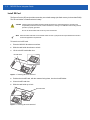
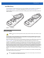

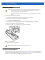


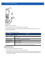

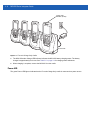
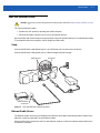
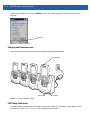
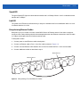

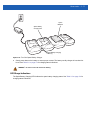
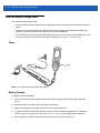


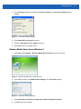

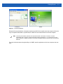


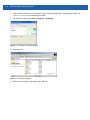


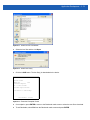


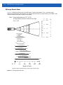

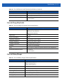
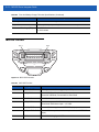
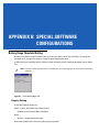


![Computador Móvel Série Mc21xx [Brazilian Portuguese] (P/N 72E](http://vs1.manualzilla.com/store/data/006087352_1-52d3c07a3e5093c41c1bf9fa502f7170-150x150.png)