1
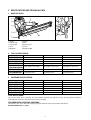
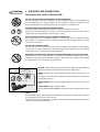
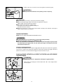
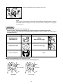
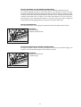
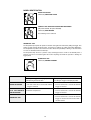
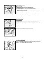
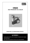
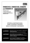
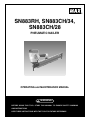
SN883RH, SN883CH/34,
SN883CH/28
PNEUMATIC NAILER
OPERATING and MAINTENANCE MANUAL
WARNING:
BEFORE USING THIS TOOL, STUDY THIS MANUAL TO ENSURE SAFETY WARNING
AND INSTRUCTIONS.
KEEP THESE INSTRUCTIONS WITH THE TOOL FOR FUTURE REFERENCE.
INDEX
ENGLISH
Page 3 to 17 Page
DEFINITIONS OF SIGNAL WORDS
WARNING:
Indicates a potentially hazardous situation which, if not avoided, could
result in death or serious injury.
CAUTION:
Indicates a potentially hazardous situation which, if not avoided, may result
in minor or moderate injury.
NOTE:
Emphasizes essential information.
2
ENGLISH
SN883RH, SN883CH/34,
SN883CH/28
PNEUMATIC NAILER
INDEX
1. SAFETY INSTRUCTIONS ……………4
2. SPECIFICATIONS &
TECHNICAL DATA……………………7
3. AIR SUPPLY AND CONNECTIONS …9
4. INSTRUCTIONS FOR OPERATION …10
5. MAINTAIN FOR PERFORMANCE …17
6. STORING ……………………………17
7. TROUBLESHOOTING/REPAIRS……17
OPERATING and MAINTENANCE MANUAL
WARNING:
BEFORE USING THIS TOOL, STUDY THIS MANUAL TO ENSURE SAFETY WARNING
AND INSTRUCTIONS.
KEEP THESE INSTRUCTIONS WITH THE TOOL FOR FUTURE REFERENCE.
3
1. SAFETY INSTRUCTIONS
WARNING:
TO AVOID SEVERE PERSONAL INJURY OR PROPERTY DAMAGE
BEFORE USING THE TOOL, READ CAREFULLY AND UNDERSTAND THE FOLLOWING
“SAFETY INSTRUCTIONS”. FAILURE TO FOLLOW WARNINGS COULD RESULT IN DEATH OR
SERIOUS INJURY.
PRECAUTIONS ON USING THE TOOL
5
70
100
WEAR SAFETY GLASSES OR GOGGLES
Danger to the eyes always exists due to the possibility of dust being blown up by the exhausted air
or of a fastener flying up due to the improper handling of the tool. For these reasons, safety glasses
or goggles shall always be worn when operating the tool.
The employer and/or user must ensure that proper eye protection is worn. Eye protection equipment
must conform to the requirements of the American National Standards Institute, ANSI Z87.1 (Council
Directive 89/686/EEC of 21 DEC. 1989) and provide both frontal and side protection.
The employer is responsible to enforce the use of eye protection equipment by the tool operator
and all other personnel in the work area.
NOTE: Non-side shielded spectacles and face shields alone do not provide adequate protection.
2.
EAR PROTECTION MAY BE REQUIRED IN SOME ENVIRONMENTS
As the working condition may include exposure to high noise levels which can lead to hearing
damage, the employer and user should ensure that any necessary hearing protection is provided and
used by the operator and others in the work area.
3.
DO NOT USE ANY POWER SOURCE EXCEPT AN AIR COMPRESSOR
The tool is designed to operate on compressed air. Do not operate the tool on any other highpressure
gas, combustible gases (e.g., oxygen, acetylene, etc.) since there is the danger of an explosion. For
this reason, absolutely do not use anything other than an air compressor to operate the tool.
4.
OPERATE WITHIN THE PROPER AIR PRESSURE RANGE
The tool is designed to operate within an air pressure range of 70 to 100 p.s.i. (5 to 7 bar).
The pressure should be adjusted to the type of the work being fastened. The tool shall never be
operated when the operating pressure exceeds 120 p.s.i. (8 bar).
Never connect the tool to air pressure which potentially exceeds 200 p.s.i. (14 bar) as the tool can
burst.
5.
DO NOT OPERATE THE TOOL NEAR A FLAMMABLE SUBSTANCE
Never operate the tool near a flammable substance (e.g., thinner, gasoline, etc.). Volatile fumes from
these substances could be drawn into the compressor and compressed together with the air and this
could result in an explosion.
6.
DO NOT USE A WRONG FITTINGS
The connector on the tool must not hold pressure when air supply is disconnected. If a wrong fitting
is used, the tool can remain charged with air after disconnecting and thus will be able to drive a
fastener even after the air line is disconnected, possibly causing injury.
7.
DISCONNECT THE AIR SUPPLY AND EMPTY THE MAGAZINE WHEN THE TOOL IS NOT
IN USE
Always disconnect the air supply from the tool and empty the magazine when operation has been
completed or suspended, when unattended, moving to a different work area, adjusting,
disassembling, or repairing the tool, and when clearing a jammed fastener.
7
1.
4
8.
INSPECT SCREW TIGHTNESS
Loose or improperly installed screws or bolts cause accidents and tool damage when the tool is put
into operation. Inspect to confirm that all screws and bolts are tight and properly installed prior to
operating the tool.
9.
DO NOT TOUCH THE TRIGGER UNLESS YOU INTEND TO DRIVE A FASTENER
Whenever the air supply is connected to the tool, never touch the trigger unless you intend to drive
a fastener into the work. It is dangerous to walk around carrying the tool with the trigger pulled, and
this and similar actions should be avoided.
10. NEVER POINT THE DISCHARGE OUTLET TOWARD YOURSELF AND OTHER PERSONNEL
If the discharge outlet is pointed toward people, serious accidents may be caused when misfiring.
Be sure the discharge outlet is not pointed toward people when connecting and disconnecting the
hose, loading and unloading the fasteners or similar operations.
11. USE SPECIFIED FASTENERS (SEE PAGE 7)
The use of fasteners other than specified fasteners will cause the tool malfunction. Be sure to use
only specified fasteners when operating the tool.
12. PLACE THE DISCHARGE OUTLET ON THE WORK SURFACE PROPERLY
Failure to place the discharge outlet of the nose in a proper manner can result in a fastener flying
up and is extremely dangerous.
13. KEEP HANDS AND BODY AWAY FROM THE DISCHARGE OUTLET
When loading and using the tool, never place a hand or any part of body in fastener discharge area
of the tool. It is very dangerous to hit the hands or body by mistake.
14. DO NOT DRIVE FASTENERS CLOSE TO THE EDGE AND CORNER OF THE WORK AND THIN
MATE RIAL
The workpiece is likely to split and the fastener could fly free and hit someone.
15. DO NOT DRIVE FASTENERS ON TOP OF OTHER FASTENERS
Driving fasteners of the top of other fasteners may cause deflection fasteners which could cause
injury.
16. REMOVING THE FASTENERS AFTER COMPLETING OPERATION
If fasteners are left in the magazine after the completion of operation, there is the danger of a serious
accident occurring prior to the resumption of operation, should the tool be handled carelessly, or
when connecting the air fitting. For this reason, always remove all fasteners remaining in the
magazine after completion of the operation.
17. CHECK OPERATION OF THE CONTACT TRIP MECHANISM FREQUENTLY IN CASE OF
USING A CONTACT TRIP TYPE TOOL
Do not use the tool if the trip is not working correctly as accidental driving of a fastener may result.
Do not interfere with the proper operation of the contact trip mechanism.
5
18. WHEN USING THE TOOL OUTSIDE OR ELEVATED PLACE
When fastening roofs or similar slanted surface, start fastening at the lower part and gradually work
your way up. Fastening backward is dangerous as you may loose your foot place.
Secure the hose at a point close to the area you are going to drive fasteners. Accidents may be
caused due to the hose being pulled inadvertently or getting caught.
19. NEVER USE THE TOOL IF ANY PORTION OF THE TOOL CONTROLS (e.g., TRIGGER, CONTACT
ARM) IS INOPERABLE, DISCONNECTED, ALTERED OR NOT WOKING PROPERLY
20. NEVER ACTUATE THE TOOL INTO FREE SPACE
This will avoid any hazard caused by free flying fasteners and excessive strain of the tool.
21. ALWAYS ASSUME THAT THE TOOL CONTAINS FASTENERS
22. RESPECT THE TOOL AS A WORKING IMPLEMENT
23. NO HORSEPLAY
24. NEVER LOAD THE TOOL WITH FASTENERS WHEN ANY ONE OF THE OPERATING CONTROLS
(e.g., TRIGGER, CONTACT ARM) IS ACTIVATED
OBSERVE THE FOLLOWING GENERAL CAUTION IN ADDITION TO
THE OTHER WARNINGS CONTAINED IN THIS MANUAL
•
•
•
•
•
•
•
Do not use the tool as a hammer.
Always carry the tool by the handle, never carry the tool by the air hose.
The tool must be used only for the purpose it was designed.
Never remove, tamper with the operating controls (e.g., TRIGGER, CONTACT ARM)
Keep the tool in a dry place out of reach of children when not in use.
Do not use the tool without Safety Warning label.
Do not modify the tool from original design or function without approval by MAX CO., LTD.
6
2. SPECIFICATIONS AND TECHNICAL DATA
1. NAME OF PARTS
i
u
w
q
r
o
e
q Frame
w Cylinder Cap
e Contact Arm
r Nose
t Magazine
y
t
!0
y Trigger
u Grip
i Exhaust Cover
o Pusher
!0 Adjustment Dial
2. TOOL SPECIFICATIONS
PRODUCT NO.
SN883RH
SN883CH/34
SN883CH/28
HEIGHT
11-7/8˝ (300 mm)
12-1/4˝ (310 mm)
12-1/4˝ (310 mm)
WIDTH
4-3/4˝ (121 mm)
4-3/4˝ (121 mm)
4-3/4˝ (121 mm)
LENGTH
20-3/4˝ (526 mm)
18-1/8˝ (460 mm)
16-7/8˝ (428 mm)
WEIGHT
7.0 lbs. (3.2 kg)
6.8 lbs. (3.1 kg)
7.0 lbs. (3.2 kg)
RECOMMENDED
OPERATING PRESSURE
70 to 100 p.s.i. (5 to 7 bar)
70 to 100 p.s.i. (5 to 7 bar)
70 to 100 p.s.i. (5 to 7 bar)
LOADING CAPACITY
64 Nails
90 Nails
90 Nails
AIR CONSUMPTION
0.077 ft3at 90 p.s.i. (6 bar)
operating pressure
0.077 ft3at 90 p.s.i. (6 bar)
operating pressure
0.077 ft3at 90 p.s.i. (6 bar)
operating pressure
3. FASTENER SPECIFICATIONS
PRODUCT NO.
SN883RH
SN883CH/34
SN883CH/28
NAIL LENGTH
2˝ to 3-1/4˝ (50 to 83 mm)
2˝ to 3-1/4˝ (50 to 83 mm)
2˝ to 3-1/4˝ (50 to 83 mm)
SHANK DIAMETER
.113˝ to .148˝ (2.9 to 3.8 mm)
.113˝ to .131˝ (2.9 to 3.3 mm)
.113˝ to .131˝ (2.9 to 3.3 mm)
SHANK TYPE
Smooth, Ring, Screw
Smooth, Ring, Screw
Smooth, Ring, Screw
HEAD DIAMETER
.267˝ to .295˝ (6.8 to 7.5 mm)
.256˝ to .303˝ (6.5 to 7.7 mm)
.256˝ to .303˝ (6.5 to 7.7 mm)
COLLATION ANGLE
21 degree
34 degree
28 degree
HEAD
Full round head
Clipped head
Clipped head
TOOL AIR FITTINGS:
This tool uses a 3/8˝ N.P.T. male plug. The inside diameter should be .39˝ (9.9mm) or larger. The fitting must be capable of
discharging tool air pressure when disconnected from the air supply.
RECOMMENDED OPERATING PRESSURE:
70 to 100 p.s.i. (5 to 7 bar). Select the operating air pressure within this range for best fastener performance.
DO NOT EXCEED 120 p.s.i. (8 bar).
7
4. TECHNICAL DATA
q NOISE
A-weighted single-event sound power level ------ LWA, 1s, d 101.03 dB
A-weighted single-event emission sound pressure level at work station ------ L p A , 1s, d 92.72 dB
These values are determined and documented in accordance to EN12549 : 1999.
w VIBRATION
Vibration characteristic value = 4.26 m/s2 (SN883RH) / 3.84 m/s2 (SN883CH/34) / 3.84 m/s2 (SN883CH/28)
These values are determined and documented in accordance to ISO 8662-11.
This value is a tool-related characteristic value and does not represent the influence to the hand-arm-system when using the tool.
An influence to the hand-arm-system when using the tool will for example depend on the gripping force, the contact pressure
force, the working direction, the adjustment of mains supply, the workpiece, the workpiece support.
5. APPLICATIONS
*Floor and wall framing
*Subflooring
*Roof and wall sheathing
*Fencing
8
WARNING:
3. AIR SUPPLY AND CONNECTIONS
Read section titled “SAFETY INSTRUCTIONS”.
DO NOT USE ANY POWER SOURCE EXCEPT AN AIR COMPRESSOR
The tool is designed to operate on compressed air. Do not operate the tool on any other highpressure
gas, combustible gases (e.g., oxygen, acetylene, etc.) since there is the danger of an explosion. For this
reason, absolutely do not use anything other than an air compressor to operate the tool.
OPERATE WITHIN THE PROPER AIR PRESSURE RANGE
The tool designed to operate within an air pressure range of 70 to 100 p.s.i. (5 to 7 bar).
The pressure should be adjusted to the type of the work being fastened. The tool shall never be
operated when the operating pressure exceeds 120 p.s.i. (8 bar).
DO NOT OPERATE THE TOOL NEAR A FLAMMABLE SUBSTANCE
Never operate the tool near a flammable substance (e.g., thinner, gasoline, etc.). Volatile fumes from
these substances could be drawn into the compressor and compressed together with the air and this
could result in an explosion.
DO NOT USE A WRONG FITTINGS
The connector on the tool must not hold pressure when air supply is disconnected. If a wrong fitting is
used, the tool can remain charged with air after disconnecting and thus will be able to drive a fastener
even after the air line is disconnected, possibly causing injury.
DISCONNECT THE AIR SUPPLY AND EMPTY THE MAGAZINE WHEN THE TOOL IS NOT IN USE
Always disconnect the air supply from the tool and empty the magazine when operation has been
completed or suspended, when unattended, moving to a different work area, adjusting, disassembling,
or repairing the tool, and when clearing a jammed fastener.
[AIR SUPPLY & CONNECTIONS]
Regulator
Air compressor
Air filter
Oiler
Air hose
3-piece airset
Used at 70 to 100 p.s.i. (5 to 7 bar)
FITTINGS: Install a male plug on the tool which is free flowing and which will release
air pressure from the tool when disconnected from the supply source.
HOSES: Hose has a min. ID of 1/4˝ (6 mm) and max. length of no more than 17˝ (5
meters).
The supply hose should contain a fitting that will provide “quick disconnecting” from
the male plug on the tool.
SUPPLY SOURCE: Use only clean regulated compressed air as a power source for
the tool.
3-PIECE AIRSET (Air filter, Regulator, Oiler):
Refer to TOOL SPECIFICATIONS for setting the correct operating pressure for the
tool.
NOTE:
A filter will help to get the best performance and minimum wear from the tool because dirt and water in
the air supply are major causes of wear in the tool.
Frequent, but not excessive, lubrication is required for the best performance. Oil added thru the air line
connection will lubricate the internal parts.
9
4. INSTRUCTIONS FOR OPERATION
Read section titled “SAFETY INSTRUCTIONS”.
1. BEFORE OPERATION
q Wear Safety Glasses or Goggles.
w Do not connect the air supply.
e Inspect screw tightness.
r Check operation of the contact arm & trigger if moving smoothly.
t Connect the air supply.
y Check the air-leakage. (The Tool must not have the air-leakage.)
u Hold the Tool with finger-off the trigger, then push the contact arm against the work-piece. (The tool
must not operate.)
i Hold the Tool with contact arm free from work-piece and pull the trigger. (The Tool must not operate.)
o Disconnect the air supply.
WARNING:
2. OPERATION
Wear safety glasses or goggles danger to the eyes always exists due to the possibility of dust being
blown up by the exhausted air or of a fastener flying up due to the improper handling of the tool. For
these reasons, safety glasses or goggles shall always be worn when operating the tool.
The employer and/or user must ensure that proper eye protection is worn. Eye protection equipment
must conform to the requirements of the American National Standards Institute, ANSI Z87.1 (Council
Directive 89/686/EEC of 21 DEC. 1989) and provide both frontal and side protection.
The employer is responsible to enforce the use of eye protection equipment by the tool operator and all
other personnel in the work area.
NOTE: Non-side shielded spectacles and face shields alone do not provide adequate protection.
WARNING:
Keep hands and body away from the discharge outlet when driving the fasteners because of dangerous
of hitting the hands or body by mistake.
NAIL LOADING
WARNING:
● When loading the nails, be sure to release the finger from the Trigger.
● Do not press the Contact Arm against the object.
Procedure
q Load the nails into the slot in the rear of the Magazine until they go over the Nail
Stopper.
Nails
Nail Stopper
10
w Pull the Pusher as far as the rear end of the magazine and release it gently.
Pusher
CAUTION:
● Abrupt release of the Pusher causes jamming of nails or dry-firing.
TEST OPERATION
q Adjust the air pressure at 70 p.s.i. (5 bar) and connect the air supply.
w Without touching the trigger, depress the contact arm against the work-piece.
Pull the trigger. (The tool must fire the fastener.)
e With the tool off the work-piece, pull the trigger.
Then depress the contact arm against the work-piece.
(The tool must fire the fastener.)
r Adjust the air pressure as much as the lowest possible according to the diameters and length of
fastener and the hardness of work-piece.
DRIVING FASTENERS
NOTE: This tool is shipped with SINGLE ACTUATION selected.
WARNING:
● To avoid double firing or accidental firing, pull the trigger rapidly and firmly.
● SINGLE ACTUATION is different from SEQUENTIAL TRIP.
● The tool with SINGLE ACTUATION drives a nail each time both when depressing the Contact
Arm while keeping the Trigger pulled, and when pullimg the Trigger and keeping it pulled after
the Contact Arm depressed.
SINGLE ACTUATION OPERATION
For SINGLE ACTUATION operation, keep the Trigger pulled and depress the Contact Arm against the
work surface, or depress the Contact Arm against the work surface and pull the Trigger and keep it
pulled. Tool cannot fire a second nail until the Trigger is released and tool can cycle.
Switching SINGLE ACTUATION to CONTACT ACTUATION with ANTI-DOUBLE
FIRE MECHANISM
WARNING:
● ALWAYS disconnect air supply before switching the triggering method.
q Gently push out the Spring Pin which indicated with “ ▼ ” mark straight with the
accessory punch.
Trigger
Accessory punch
Spring Pin
11
w Remove the Switching Lever to the direction of the arrow.
Spring Pin
Switching Lever
NOTE:
When switching back CONTACT ACTUATION with ANTI-DOUBLE FIRE MECHANISM to SINGLE
ACTUATION, equip the Switching Lever facing “S” mark front with the Spring Pin to the Trigger by
reverse procedure.
WARNING:
● Use sintering steel grey metallic color Switching Lever
Confirm and use the designated original Switching Lever when carrying out the switching back procedure.
The use of Switching Lever other than the designated original one will cause serious accidents. (e.g., firing fasteners
just pulling trigger, etc.)
Color
Shape (1/1 scale)
Tool
NF550
SINTERING STEEL
GREY METALLIC
SN883 with thin trigger
STAINLESS SILVER
SN883 with thick trigger
STEEL BLACKENING
HS90A
● Never install the Switching Lever to the Previous model
It will cause serious accidents. (e.g., firing fasteners just pulling trigger, etc)
Projection Shape
This model
Flat Shape
Previous model
12
CONTACT TRIP MODEL with ANTI-DOUBLE FIRE MECHANISM
The anti-double fire mechanism (US patent 5597106, UK patent 2286790) is installed on this tool.
The common operating procedure on “Contact Trip” tools is for the operator to contact the work to
actuate the trip mechanism while keeping the trigger pulled, thus driving a fastener each time the work is
contacted. This will allow rapid fastener placement on many jobs, such as sheathing, decking and pallet
assembly. All pneumatic tools are subject to recoil when driving fasteners. The tool may bounce,
releasing the trip, and if unintentionally allowed to re-contact the work surface with the trigger still
actuated (finger still holding trigger pulled) an unwanted second fastener will be driven.
CONTACT FIRE OPERATION
For contact fire operation, hold the Trigger and depress the Contact Arm against the work surface.
1
PROCEDURE
q Hold the Trigger.
w Depress the Contact Arm.
2
SINGLE FIRE OPERATION (ANTI-DOUBLE FIRE MECHANISM)
For single fire operation, depress the Contact Arm against the work surface and pull the Trigger. Tool
cannot fire a second nail until the Trigger is released and tool can cycle.
2
PROCEDURE
q Depress the Contact Arm.
w Pull the Trigger.
1
13
MODEL IDENTIFICATION
Switching Lever
SINGLE ACTUATION
Identified by SWITCHING LEVER.
CONTACT TRIP WITH ANTI-DOUBLE FIRE MECHANISM
(US patent 5597106, UK patent 2286790)
Identified by RED TRIGGER.
The Switching Lever is removed.
SEQUENTIAL TRIP
The Sequential Trip requires the operator to hold the tool against the work before pulling the trigger. This
makes accurate fastener placement easier, for instance on framing, toe nailing and crating applications.
The Sequential Trip allows exact fastener location without the possibility of driving a second fastener
on recoil, as described under “Contact Trip”.
The Sequential Trip Tool has a positive safety advantage because it will not accidentally drive a
fastener if the tool is contacted against the work-or anything else-while the operator is holding the
trigger pulled.
SEQUENTIAL TRIP
Identified by ORANGE TRIGGER.
PROCEDURE
SINGLE ACTUATION
CONTACT ACTUATION
WITH ANTI-DOUBLE
FIRE MECHANISM
q Pulling the Trigger and keeping it pulled.
w Depressing the Contact Arm.
q Depressing the Contact Arm.
w Pulling the Trigger and keeping it pulled.
・ The tool fires a nail.
・ The tool cannot fire a second nail until the
Trigger is released.
・ The tool fires a nail.
・ The tool cannot fire a second nail until the
Trigger is released.
The tool fires a nail each time when the
Contact Arm is depressed.
・ The tool fires a nail.
・ The tool cannot fire a second nail until the
Trigger is released.
The tool cannot fire a nail.
・ The tool fires a nail.
・ The tool cannot fire a second nail until the
Trigger is released and the Contact Arm is
left work surface.
SEQUENTIAL TRIP
14
DRIVING DEPTH ADJUSTMENT
Adjustment Dial
WARNING:
ALWAYS disconnect air supply before making adjustment.
Deeper
The driving depth adjustment is made by adjusting the Adjustment Dial.
Shallow
q With air pressure set, drive a few nails into a representative material sample to
determine if adjustment is necessary.
w If adjustment is required, disconnect air supply.
e Refer to the mark on the Contact Arm area for direction to turn the Adjustment Dial.
r Re-connect air supply.
CONTACT TIP (OPTION)
WARNING:
ALWAYS disconnect air supply before attaching / detaching the Contact Tip.
Attach the Contact Tip on the tip of Contact Arm “B”, when driving nails to a soft
material.
Contact Arm “B”
Contact Tip
The Contact Tip can be kept at the Arm Cover when not using.
Contact Tip
Arm Cover
TRIGGER LOCK MECHANISM
The tool is equipped with a Trigger Lock Mechanism. Push and rotate the Trigger from
LOCK to the Trigger UNLOCK position before driving nails.
LOCK
Trigger Lock Dial
UNLOCK
Trigger
15
REMOVING JAMMED NAILS
WARNING:
ALWAYS disconnect air supply before removing jammed nails.
q Push the Pusher Lever and release the strip nails from the Pusher.
Pusher Lever
w Push the Nail Stopper, and remove the strip nails from inside of the Magazine.
Nail Stopper
e Pull and stayed the Pusher back using the hole and a rod.
r Remove the jammed nail from the Nose using a punch or a slotted screw driver.
Rod
Hole
Pusher
WARNING:
● Nails are held in the Nose of the tool by magnet. (SN883RH)
Magnet
Remaining nail
This tool equips a magnet in the Nose to drive out all nails loaded in the Magazine.
Therefore, in the case the collation strip is broken, there are nails remaining in the Nose
even if you think that you removed whole nails. In this case, there is possibility of
serious accident if you think that there are no nails and activate the tool. For that
reason, when you remove the nails from the Magazine, confirm that there are no nails in
the Nose besides disconnect air supply.
16
5. MAINTAIN FOR PERFORMANCE
q DO NOT FIRE THE NAILER WHEN IT IS EMPTY
w USE A 3-PIECE AIRSET
Failure to use a 3-piece airset allows the moisture and dirt inside compressor to pass into the tool
directly. This causes rust and wear, and results in a poor operating performance. The hose length
between airset and tool should be no longer than 5 m since a longer length results in a reduction in air
pressure.
e USE RECOMMENDED OIL
The velocite or turbine oil should be used to lubricate the tool. Upon completion of operations, place 2
or 3 drops of oil into the air plug inlet with the jet oiler. (Recommended Oil : ISO VG32)
r INSPECT AND MAINTAIN DAILY OR BEFORE OPERATION
WARNING:
Disconnect air supply and empty the magazine when inspecting or maintaining the tool.
(1) Drain air line filter and compressor
(2) Keep lubricator filled in air 3-pieces set
(3) Clean filter element of air 3-pieces set
(4) Tighten all screws
(5) Keep contact arm moving smoothly
6. STORING
q When not in use for an extended period, apply a thin coat of the lubricant to the steel parts to avoid
rust.
w Do not store the tool in a cold weather environment. Keep the tool in a warm area.
e When not in use, the tool should be stored in a warm and dry place. Keep out of reach of children.
r All quality tools will eventually require servicing or replacement of parts because of wear from the
normal use.
7. TROUBLE SHOOTING/REPAIRS
The troubleshooting and/or repairs shall be carried out only by the MAX CO., LTD. authorised distributors
or by other specialists.
Supplement to the operating instruction
According to the European Norm EN 792-13 the regulation is valid from 01.01.2001 that all fastener
driving tools with contact actuation must be marked with the symbol “Do not use on scaffoldings,
ladders” and they shall not be used for specific application for example:
* when changing one driving location to another involves the use of scaffoldings, stairs, ladders or
ladder alike constructions e.g. roof laths,
* closing boxes or crates,
* fitting transportation safety systems e.g. on vehicles and wagons.
17
Recycled paper is used for this manual and its recyclable.
• The content of this manual might be changed without notice for improvement.
〔
6-6 NIHONBASHI-HAKOZAKI-CHO, CHUO-KU, TOKYO, JAPAN
Tel: (03) 3669-8131 Telefax: (03) 3669-7104
〕
www.maxusacorp.com (USA Site)
www.max-ltd.co.jp/int/ (GLOBAL Site)
www.max-europe.com
★071205-00/00
PRINTED IN JAPAN