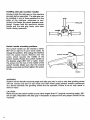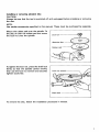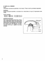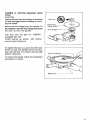
1
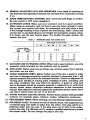
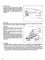
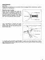
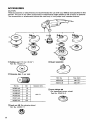
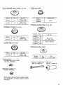
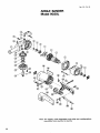
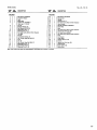
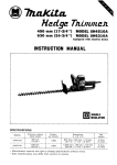
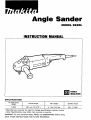
INSTRUCTION MANUAL
DOUBLE
INSULATION
No load speed
(RPM)
Overall length
Net weight
Spindle thread
6,000
462 mm ( 18-3/16")
4.7 kg (10.4 lbsl
5 / 8 - 1 1 UNC
IMPORTANT
SAFETY INSTRUCTIONS
(For All Tools)
WARNING: WHEN USING ELECTRIC TOOLS, BASIC SAFETY
PRECAUTIONS SHOULD ALWAYS BE FOLLOWED TO REDUCE
THE RISK OF FIRE, ELECTRIC SHOCK, AND PERSONAL
INJURY, INCLUDING THE FOLLOWING:
READ ALL INSTRUCTIONS.
1. KEEP WORK AREA CLEAN. Cluttered areas and benches invite injuries.
2. CONSIDER WORK AREA ENVIRONMENT. Don't use power tools in damp
or wet locations. Keep work area well lit. Don't expose power tools to rain.
Don't use tool in presence of flammable liquids or gases.
3. KEEP CHILDREN AWAY. All visitors should be kept away from work area.
Don't let visitors contact tool or extension cord.
4. STORE IDLE TOOLS. When not in use, tools should be stored in dry, and high
or locked-up place - out of reach of children.
5 . DON'T FORCE TOOL. It will do the job better and safer at the rate for which
it was intended.
6. USE RIGHT TOOL. Don't force small tool or attachment to do the job of a
heavy-duty tool. Don't use tool for purpose not intended.
7 . DRESS PROPERLY. Don't wear loose clothing or jewelry. They can be caught
in moving parts. Rubber gloves and non-skid footwear are recommended
when working outdoors. Wear protective hair covering to contain long hair.
8 . USE SAFETY GLASSES. Also use face or dust mask if cutting operation is
dusty.
9. DON'T ABUSE CORD. Never carry tool by cord or yank it to disconnect from
receptacle. Keep cord from heat, oil, and sharp edges.
10. SECURE WORK. Use clamps or a vise to hold work. It's safer than using
your hand and it frees both hands to operate tool.
11. DON'T OVERREACH. Keep proper footing and balance at all times.
12. MAINTAIN TOOLS WITH CARE. Keep tools sharp and clean for better and
safer performance. Follow instructions for lubricating and changing accessories. Inspect tool cords periodically and if damaged, have repaired by authorized service facility. Inspect extension cords periodically and replace if
damaged. Keep handles dry, clean, and free from oil and grease.
13. DISCONNECT TOOLS. When not in use, before servicing, and when changing accessories, such as blades, bits, cutters.
2
14. REMOVE ADJUSTING KEYS AND WRENCHES. Form habit of checking to
see that keys and adjusting wrenches are removed from tool before turning
it on.
15. AVOID UNINTENTIONAL STARTING. Don't carry tool with finger on switch.
Be sure switch is OFF when plugging in.
16. EXTENSION CORDS. Make sure your extension cord is in good condition.
When using an extension cord, be sure to use one heavy enough to carry
the current your product will draw. An undersized cord will cause a drop
in line voltage resulting in loss of power and overheating. Table 1 shows the
correct size to use depending on cord length and nameplate ampere rating.
If in doubt, use the next heavier gage. The smaller the gage number, the
heavier the cord.
TABLE 1 MINIMUM GAGE FOR CORD SETS
I
I
Total Length of Cord in Feet
0
- 25
I
26
- 50
Ampere Rating
More
Not MOW
Than
Than
0
6
10
12
-
-
6
10
12
16
I
51
- 100
I
:9
1
101
- 150
AWG
18
18
16
14
16
16
16
12
14
12
14
12
Not Recommended
17. OUTDOOR USE EXTENSION CORDS. When tool is used outdoors, use only
extension cords intended for use outdoors and so marked.
18. STAY ALERT, Watch what you are doing, use common sense. Don't operate
tool when you are tired.
19. CHECK DAMAGED PARTS. Before further use of the tool, a guard or other
part that is damaged should be carefully checked to determine that it will
operate properly and perform its intended function. Check for alignment of
moving parts, binding of moving parts, breakage of parts, mounting, and
any other conditions that may affect its operation. A guard or other part
that is damaged should be properly repaired or replaced by an authorized
service center unless otherwise indicated elsewhere in this instruction
manual. Have defective switches replaced by authorized service center. Don't
use tool if switch does not turn it on and off.
20. GUARD AGAINST ELECTRIC SHOCK. Prevent body contact with grounded
surfaces. For example; pipes, radiators, ranges, refrigerator enclosures.
21. REPLACEMENT PARTS. When servicing, use only identical replacement parts.
22. POLARIZED PLUGS. To reduce the risk of electric shock, this equipment has
a polarized plug (one blade is wider than the other). This plug will fit in a
polarized outlet only one way. If the plug does not fit fully in the outlet,
reverse the plug. If it still does not fit, contact a qualified electrician to install
the proper outlet. Do not change the plug in any way.
3
VOLTAGE WARNING: Before connecting the tool to a power source (receptacle.
outlet, etc.) be sure the voltage supplied is the same as that specified on the
nameplate of the tool. A power source with voltage greater than that specified
for the tool can result in SERIOUS INJURY to the user - as well as damage to
the tool. If in doubt, DO NOT PLUG IN THE TOOL. Using a power source with
voltage less than the nameplate rating is harmful to the motor.
ADDITIONAL SAFETY RULES FOR SANDER
1. Check the backing pad carefully for cracks, damage or deformity before
operation. Replace cracked, damaged or deformed pad immediately.
2. Hold the tool firmly.
3. Keep hands away from rotating parts.
4. Make sure abrasive disc is not contacting the workpiece before the switch
is turned on.
5. Do not leave the tool running. Operate the tool only when hand-held.
6. Do not touch the workpiece immediately after operation; it may be extremely
hot and could burn your skin.
4
ADDITIONAL SAFETY RULES FOR GRINDER
1. Keep guards in place.
2. Use only wheels having a maximum operating speed at least as high as "No
Load RPM" marked on the tool's nameplate. When using depressed center
wheels, be sure to use only fiberglass-reinforced wheels.
3. Check the wheel carefully for cracks or damage before operation. Replace
cracked or damaged wheel immediately.
4. Use only flanges specified for this tool.
5. Be careful not to damage the spindle, the flange (especially the installing
surface) or the lock nut. Damage to these parts could result in wheel
breakage.
6. Hold the tool firmly.
7. Keep hands away from rotating parts.
8. Make sure the wheel is not contacting the workpiece before the switch is
turned on.
9. Before using the tool on an actual workpiece, let it run for a while. Watch
for vibration or wobbling that could indicate poor installation or a poorly
balanced wheel.
10. Use the specified surface of the wheel to perform the grinding.
11. Watch out for flying sparks. Hold the tool so that sparks fly away from you
and other persons or flammable materials.
12. Do not leave the tool running. Operate the tool only when hand-held.
13. Do not touch the workpiece immediately after operation; it may be extremely
hot and could burn your skin.
SAVE THESE INSTRUCTIONS.
5
Installing side grip (auxiliary handle)
Always install the side grip on the machine
securely before operation. The side grip can
be installed in any of three positions on the
sides of the machine, whichever is convenient and keeps the guard properly positioned. Always hold the machine's switch
handle and the side grip firmly with both
hands during operation.
L
Side grip
Switch handle mounting positions
The switch handle can be rotated to either
90° left or right to fit your work needs. To
change the position, first unplug the machine
from the power source. Remove only the
screw which secures the middle of the
switch handle Rotate the switch handle to
the desired angle (90° left or right). Insert
the screw into the hole in the middle of the
switch handle. Make sure that the switch
handle is secured and then tighten the screw
firmly.
Screw
WARNING:
Position switch handle mounting angle and side grip only in such a way that grinding wheel
will not contact any part of your body and that wheel guard always remains positioned
as a barrier between the grinding wheel and the operator. Failure to do so may result in
serious injury.
CAUTION:
Never mount the switch handle at any other angles than Oo (original mounting angle), 90°
left of right. Reposition the side grip if necessary to assure firm and proper control of the
machine.
6
Installing or removing abrasive disc
CAUTION:
Always be sure that the tool is switched off and unplugged before installing or removing
the disc.
NOTE:
Use sander accessories specified in this manual. These must be purchased by separate.
Mount the rubber pad onto the spindle. Fit
the disc OR over the rubber pad and screw
the lock nut onto the spindle.
Lock nut
I
To tighten the lock nut, press the shaft lock
firmly so that the spindle cannot revolve,
then use the lock nut wrench and securely
tighten clockwise.
Lock n u t w r e n c h
~
To remove the disc, follow the installation procedure in reverse.
7
IF USED AS A GRINDER
NOTE:
Use grinder accessories specified in this manual. These must be purchased separately.
WARNING:
Always use guard assembly or accessory kit, noted below, for type 27 depressed center
wheel.
Guard assembly
Part No. 192413-0
Part No. 192414-8
... For 180 mm (7")
... For 230 mm 19")
Installingwheel guard
When using a depressed center wheel, always
use a wheel guard. Mount the wheel guard
with the tab on the wheel guard band aligned
with the notch on the bearing box.Then rotate
the wheel guard 160 degrees counterclockwise. Be sure to tighten the screw
securely.
c
I
8
Wheel guard
screw
1
Notch
Installing or removing depressed center
wheel
CAUTION:
Always be sure that the machine is switched
off and unplugged before installing or removing the wheel.
Mount the inner flange onto the spindle. Fit
Lock nut
-
Depressed
center whee
the wheel on over the inner flange and screw
the lock nut onto the spindle.
Use only lock nut part no. 192568-1,
equipped with tool.
Install locknut as shown, with locknut
wrench holes facing out.
To tighten the lock nut, press the shaft lock
firmly so that the spindle cannot revolve,
then use the lock nut wrench and securely
tighten clockwise.
Lock nut wrench
>
/
-
To remove the wheel, follow the installation
procedure in reverse.
Shaft lock
--
9
Switch action
To start the tool, simply pull the trigger.
Release the trigger to stop. For continuous
operation, pull the trigger and then push in
the lock lever. To stop the tool form the
locked position, pull the trigger fully, then
release it.
Lock lever
CAUTION:
Before plugging in the tool, always check to see that the switch trigger actuates properly
and returns t o the "OFF" position when released.
Operation
Hold the tool firmly. Turn the tool on and
then apply the wheel or disc to the workpiece.
In general, keep the edge of the wheel or
disc at an angle of about 1 5 O to the workpiece surface.
During the break-in period with a new wheel,
do not work the grinder in the B direction or
it will cut into the workpiece. Once the edge
of the wheel has been rounded off by use,
the wheel may be worked in both A and B
directions.
I
-
WARNING:
It should never be necessary to force the tool. The weight of the tool applies adequate
pressure. Forcing and excessive pressure could cause dangerous wheel breakage.
Continued use of a worn-out wheel may result in wheel explosion and serious personal
injury. Depressed center wheel should not be used after it has been worn down to
115 mm (4-112") in diameter. Use of the wheel after this point is unsafe and it should
be removed from service and rendered unusable by intentional destruction.
10
MAINTENANCE
CAUTION:
Always be sure that the tool is switched off and unplugged before attempting to perform
inspection or maintenance.
Replacing carbon brushes
When the resin insulating tip inside the
carbon brush is exposed to contact the
commutator, it will automatically shut off
the motor. When this occurs, both carbon
brushes should be replaced at the same
time. Use only identical carbon brushes.
>
7
Insulating tip
1
-
Carbon brush
Use a screwdriver to remove the brush
holder caps. Take out the worn carbon
brushes, insert the new ones and secure the
brush holder caps.
I
,
Brush holder cap
To maintain product SAFETY and RELIABILITY, repairs, any other maintenance or adjustment should be performed by Makita Authorized or Factory Service Centers, always using
Makita replacement parts.
11
ACCESSORIES
CAUTION:
These accessories or attachments are recommended for use with your Makita tool specified in this
manual. The use of any other accessories or attachments might present a risk of injury to persons.
The accessories or attachments should be used only in the proper and intended manner.
I
I
I
@Guard assembly
@Rubber pad 170 mm (6-3/4")
Part No. 743012-7
@Abrasive disc (5 per pkg)
Part No.
I
Size (mm)
~
PartNo.
I
Grit
I
742067-A-5
I
16
I
742069-A-5
I
24
I
742089-A-5
Diameter I
742071-A-5
742091-A-5
120
@Lock nut 48 (For abrasive discs)
Part No. 22451 7-1
12
180 (7")
192414-8
230 19")
n"
180 17")
742070-A-5
1 9 2 4 13-0
@Inner flahge 89
(For depressed center wheel)
Part No. 22431 5-3
@(A) Depressed center wheel (1 per pkg)
Part No.
741413-3
I
I
741421-4
Grit
24
I
I
I
Size (mm)
Part No.
x 6 x 22
(7,, 180114,
718,,)
743206-A
230 x 6 x 22
(9" x 1/4" x 7 / 6 7
24
@Wire cup brush
Diameter (mml
150 16')
743206-8
@Flexible grinding wheel (10 per pkg)
(B) Makita zirconate (5 per pkg)
Part N a
Part No.
I
741313-7A
Grit
Size (mml
24
180 x 6 x 22
,7,,
114, 718,,)
741445-0
I
Grit
I
Size (mml
36
(7" x 118" x 718")
741443-4
(C) Best edge (5 per pkgl
I
741444-2
I
I
80
I
120
I
.
Part No. 74302f-4).
-
@Hubbed grinding wheel
Part No.
741413-6A
I
I
Grit
24
I
I
Size (mml
(7,,
180118"
x 3 x 22
718,,)
Part N a
Grit
Size
741414-A
A24R
7" x 114' x 98''
@Lock nut 45
(For depressed center wheel)
Part No. 192568-1
Lock nut wrench 28
Part No. 7 8 2 4 1 2-6
Grip 35
Part No. 273503-9
@Urethane washer 14
Part No. 261039-0
When using wire brush, mount urethane washer
14 to the spindle. It will make it easier to remove
wire brush.
13
fib-03-'94
US
ANGLE SANDER
Model 9020L
Note: The switch, noise suppressor and other part configurations
may differ from country to country.
14
MODEL 9020L
ITEM
NO.
Feb-03-'94
NO.
USED
ITEM
NO.
DEscWPTIDN
MA1 NE
-
1
2
3
4
5
6
7
8
9
10
11
12
13
14
15
16
17
18
19
20
21
1
1
1
1
1
1
1
1
1
1
4
1
1
1
1
1
1
1
1
1
1
US
NO.
USED
DEsCRIPTON
MACHINE
~
Ball Bsannp 62MK)DW
I"."l.tlgn
w..her
Field
Baffle Plate
ARMATURE ASSEMBCY
(With Item 1, 2 h 61
Fan 80
Bamng Retalnmr 57
Ball Bsanng 6301DDW
S p n l B a V d Gem 12
Ratammg Ring S-9
Pan b a d Screw M5x40 IWith Washer1
Tool Rasl
Rn Cap
Compression Spring 12
Hex Socket Head Bolt M5r20
Pm 6
Grip 35
Hex Sockel Head Bolt M5x10
RetaininQRing 5-17
Spral B s V d Gear 50
Retmmma R i m R - 4 0
Nom: The switch and o h r pan ap&ficmbns
may differ fmm
22
23
24
25
26
27
28
29
30
31
32
33
34
35
36
37
38
39
40
42
43
44
-
1
1
1
1
4
1
1
1
1
2
1
1
4
1
1
1
2
1
1
2
2
1
-
Ball Bserinp 6203DDW
Bssnng Box
Spmdle
Wwdruff Key 4
Pan Head Screw M S x l 6 IWith Washer1
Gear Housmg
MOTOR HOUSING ASSEMBLY
Name Plate
Band
Pan Head Screw M5x70 IWith Washer1
Handle Set (With Item 451
Pan Head Screw M6r85
Pan Head Screw M4x25 IWilh Washer1
Cord
Cwd Guard
Stram R e l d
Tappmg k r s w 4x18
Switch
Handle Set IWbth Item 361
Carbon h s h
Brush Holder Cap
MakLa Mark
comity to country.
15
MAKITA LIMrrED ONE YEAR WARRAECTY
Warranty Policy
Every Makita tool is thoroughly inspected and tested before leaving the factory. It is warranted to
be free of defects from worlananship and materials for the period of ONE YEAR from the date of
original purchase. Should any trouble develop during this one-year period. retum the COMPLETE
tool, freight prepaid, to one of Makita’s Factory or Authorized Service Centers. If inspection shows
the trouble is caused by defective workmanship or material, Makita will repair (or at our option,
replace) without charge.
This Warranty does not apply where:
0 repairs have been made or attempted by others:
0 repairs are required because of normal wear and tear:
The tool has been abused, misused or improperly maintained;
0 alterations have been made to the tool.
I N NO EVENT SHALL MAKlTA BE LIABLE FOR ANY INDIRECT. INCIDENTAL OR CONSEQUENTIAL DAMAGES FROM THE SALE OR USE OF THE PRODUCT. THIS DISCLAIMER
APPLIES BOTH DURING AND AFTER THE TERM OF THIS WARRANTY.
MAKITA DISCLAIMS LIABILITY FOR ANY IMPLIED WARRANTIES, INCLUDING IMPLIED
WARRANTIES OF “MERCHANTABILITY” AND “FITNESS FOR A SPECIFIC PURPOSE,”
AFTER THE ONE-YEAR TERM O F THIS WARRANTY.
This Warranty gives you specific legal rights, and you may also have other rights which vary from
state to state. Some states do not allow the exclusion or limitation of incidental or consequential
damages, so the above limitation or exclusion may not apply to you. Some states do not allow
limitation on how long an implied warranty lasts, so the above limitation may not apply to you.
-
MAKITA MANUFACTURING EUROPE LTD
TELFORD, SHROPSHIRE, U.K.
883880-
069
SM-1095-8M
MA-1930-95