1
Confidential
SR-600
Specification
STANDARD
Rev. No.
A
Notes
Copied Date
,
,
Copied by
SEIKO EPSON CORPORATION
MATSUMOTO MINAMI PLANT
2070 KOTOBUKI KOAKA, MATSUMOTO-SHI, NAGANO, 399-8702 JAPAN
PHONE(0263)86-5353 FAX(0263)86-9925
Confidential
REVISION SHEET
Sheet 1 of 2
The table below indicates which pages in this specification have been revised.
Before reading this specification, be sure you have the correct version of each page.
Revisions
Rev.
A
Document
Enactment
Design Section
Sheet Rev. No.
WRT
CHK
APL
Sheet
Okizaki
Takahashi
Miyagawa
I
A
II
A
III
A
1
A
2
A
3
A
4
A
5
A
6
A
7
A
8
A
9
A
10
A
11
A
12
A
13
A
14
A
15
A
16
A
17
A
TITLE
Rev. Sheet Rev.
Sheet
Rev.
Front Part
SR-600
Specification
(STANDARD)
Cover
Rev.
Sheet
Scope
General
Description
Table of
Contents
Contents
Appendix
Total
1
2
−
1
2
17
−
23
Confidential
REVISION SHEET
Sheet 2 of 2
REV.
SHEET
A
All
CHANGED CONTENTS
The specifications of the IM-600 and the DM-LS121T are combined.
TITLE
SR-600
Specification
(STANDARD)
Confidential
CONFIDENTIALITY AGREEMENT
BY USING THIS DOCUMENT, YOU AGREE TO ABIDE BY THE TERMS OF THIS AGREEMENT. PLEASE
RETURN THIS DOCUMENT IMMEDIATELY IF YOU DO NOT AGREE TO THESE TERMS.
1. This document contains confidential, proprietary information of Seiko Epson Corporation or its affiliates.
You must keep such information confidential. If the user is a business entity or organization, you must
limit disclosure to your employees, agents, and contractors who have a need to know and who are also
bound by obligations of confidentiality.
2. On the earlier of (a) termination of your relationship with Seiko Epson, or (b) Seiko Epson’s request, you
must stop using the confidential information. You must then return or destroy the information, as directed
by Seiko Epson.
3. If a court, arbitrator, government agency, or the like orders you to disclose any confidential information,
you must immediately notify Seiko Epson. You agree to give Seiko Epson reasonable cooperation and
assistance in resisting disclosure.
4. You may use confidential information only for the purpose of operating or servicing the products to which
the document relates, unless you obtain the prior written consent of Seiko Epson for some other use.
5. Seiko Epson warrants that it has the right to disclose the confidential information. SEIKO EPSON
MAKES NO OTHER WARRANTIES CONCERNING THE CONFIDENTIAL INFORMATION OR ANY
OTHER INFORMATION IN THE DOCUMENT, INCLUDING (WITHOUT LIMITATION) ANY
WARRANTY OF TITLE OR NON-INFRINGEMENT. Seiko Epson has no liability for loss or damage
arising from or relating to your use of or reliance on the information in the document.
6. You may not reproduce, store or transmit the confidential information in any form or by any means
(electronic, mechanical, photocopying, recording, or otherwise) without the prior written permission of
Seiko Epson.
7. Your obligations under this Agreement are in addition to any other legal obligations. Seiko Epson does
not waive any right under this Agreement by failing to exercise it. The laws of Japan apply to this
Agreement.
CAUTIONS
1. This document shall apply only to the product(s) identified herein.
2. No part of this document may be reproduced, stored in a retrieval system, or transmitted in any form or
by any means, electronic, mechanical, photocopying, recording, or otherwise, without the prior written
permission of Seiko Epson Corporation.
3. The contents of this document are subject to change without notice. Please contact us for the latest
information.
4. While every precaution has been taken in the preparation of this document, Seiko Epson Corporation
assumes no responsibility for errors or omissions.
5. Neither is any liability assumed for damages resulting from the use of the information contained herein.
6. Neither Seiko Epson Corporation nor its affiliates shall be liable to the purchaser of this product or third
parties for damages, losses, costs, or expenses incurred by the purchaser or third parties as a result of:
accident, misuse, or abuse of this product or unauthorized modifications, repairs, or alterations to this
product, or (excluding the U. S.) failure to strictly comply with Seiko Epson Corporation's operating and
maintenance instructions.
7. Seiko Epson Corporation shall not be liable against any damages or problems arising from the use of
any options or any consumable products other than those designated as Original EPSON Products or
EPSON Approved Products by Seiko Epson Corporation.
TRADEMARKS
®
®
EPSON and ESC/POS are registered trademarks of Seiko Epson Corporation.
®
TM
Intel and Celeron are either trademarks or registered trademarks of Intel Corporation.
®
®
®
®
MS-DOS , Microsoft , Windows and Windows NT are registered trademarks of Microsoft Corporation.
TM
CompactFlash is a trademark of SanDisk Corporation.
General Notice: Other product and company names used herein are for identification purposes only and may
be trademarks of their respective companies.
TITLE
SR-600
Specification
(STANDARD)
SHEET
REVISION
A
NO.
NEXT
SHEET
II
I
Confidential
TABLE OF CONTENTS
1. APPLICATION......................................................................................................................................1
2. GENERAL DESCRIPTIONS ................................................................................................................1
2.1 Features.........................................................................................................................................1
2.2 Accessories....................................................................................................................................1
2.3 Related Documents .......................................................................................................................1
3. GENERAL SPECIFICATIONS .............................................................................................................2
3.1 Summary of Specifications ............................................................................................................2
3.1.1 IM-600 specifications.............................................................................................................2
3.1.2 DM-LS121T specifications.....................................................................................................3
3.2 External Dimensions ......................................................................................................................4
3.3 EMI and Safety Standards Applied ................................................................................................5
3.3.1 For North America .................................................................................................................5
3.3.2 For Europe.............................................................................................................................5
3.3.3 For Japan ..............................................................................................................................5
3.3.4 For other countries ................................................................................................................5
3.4 Environmental Specifications.........................................................................................................6
3.4.1 Temperature ..........................................................................................................................6
3.4.2 Humidity.................................................................................................................................6
3.4.3 Vibration resistance ...............................................................................................................6
3.4.4 Impact resistance ..................................................................................................................6
3.5 Reliability........................................................................................................................................7
3.5.1 MTBF .....................................................................................................................................7
3.5.2 Life .........................................................................................................................................7
3.6 Power Consumption.......................................................................................................................7
3.7 Power Supply .................................................................................................................................8
3.7.1 Power supply capacity to external devices ............................................................................8
3.7.2 Lithium rechargeable battery .................................................................................................8
4. BASE UNIT STRUCTURE ...................................................................................................................9
4.1 Terminal Front Panel (IM-600).......................................................................................................9
4.1.1 Front Power Switch................................................................................................................9
4.1.2 Reset Switch..........................................................................................................................9
4.1.3 Speaker Volume Control .......................................................................................................9
4.1.4 Front Cover Lock ...................................................................................................................9
4.1.5 Floppy Disk Drive Connector .................................................................................................9
4.1.6 Keyboard/mouse....................................................................................................................9
4.2 Terminal Rear Panel (IM-600) .....................................................................................................10
4.2.1 Main Power Switch ..............................................................................................................10
4.2.2 Power Connector .................................................................................................................10
4.2.3 Customer Display Connector...............................................................................................10
4.2.4 Power Supply Fan ...............................................................................................................10
4.3 Structure of the LCD (DM-LS121T) .............................................................................................11
4.3.1 Indicators .............................................................................................................................11
4.3.2 Adjusting backlight brightness .............................................................................................11
4.3.3 MSR Unit Connector............................................................................................................11
4.3.4 Base Unit Interface Cable....................................................................................................11
TITLE
SR-600
Specification
(STANDARD)
SHEET
REVISION
A
NO.
NEXT
SHEET
III
II
Confidential
4.4 Circuit Board Configuration (IM-600) ...........................................................................................12
4.4.1 Motherboard ........................................................................................................................12
4.4.2 Video Board .........................................................................................................................12
4.4.3 I/O Board .............................................................................................................................12
4.4.4 PCI Board ............................................................................................................................13
4.4.5 VR Board .............................................................................................................................13
4.4.6 Drawer Board (Option) ........................................................................................................13
4.5 Miscellaneous ..............................................................................................................................13
4.5.1 CPU .....................................................................................................................................13
4.5.2 DIMM ...................................................................................................................................13
4.5.3 Hard Disk Drive ...................................................................................................................13
4.5.4 PCI Slot................................................................................................................................13
4.6 Cautions .......................................................................................................................................14
5. SOFTWARE SPECIFICATIONS ........................................................................................................15
5.1 Available operating systems ........................................................................................................15
5.2 Available Driver Software.............................................................................................................15
5.3 Available Tools.............................................................................................................................15
5.4 Available utilities...........................................................................................................................15
5.5 OPOS...........................................................................................................................................15
6. OPTIONS ...........................................................................................................................................16
6.1 Factory Options............................................................................................................................16
6.2 User Options ................................................................................................................................17
6.3 Precautions Related to Internal Components ..............................................................................17
TITLE
SR-600
Specification
(STANDARD)
SHEET
REVISION
A
NO.
NEXT
SHEET
1
III
Confidential
1. APPLICATION
This product specification applies to the SR-600 POS terminal system.
2. GENERAL DESCRIPTIONS
2.1 Features
The IM-600 is a base unit of the SR terminal. Designed for use in hospitality, and other high-end
establishments, it provides the following features;
•
•
•
•
•
•
•
•
•
•
•
•
•
•
•
•
•
•
®
®
IBM PC/AT compatible
®
TM
Intel Celeron (PPGA package: up to 366 MHz, FCPGA package: up to 733 MHz) can be used.
Two 168-pin DIMM sockets are ready for a maximum 512MB of memory.
2 MB video memory installed with the video controller in the PCI bus.
TFT 12.1-inch color liquid crystal display.
TM
Two disk spaces are available for 2.5-inch hard disk drive, CD-ROM drive or CompactFlash
card.
An Ethernet controller for 10BASE-T/100BASE-TX is installed in the PCI bus.
One PCI expansion slot (PCI version 2.1 compliant.)
Cash Drawer/CRT interface board available as a factory option.
A customer display can be installed as an user option.
Case lock prevents unauthorized access to the inside of the terminal.
Display angle adjustable from 20 to 65 degrees.
Maximum dimensions are 310 (W) × 363 (D) × 277 (H) mm (including rubber feet, excluding LCD
clamp.)
A high resolution display of 800x600 dots, using 12.1-inch color TFT LCD.
A high-luminance backlight with 350 cd/m (except for touch panel).
Input by finger using the resistive film type of the touch panel.
Water-resistant surface on the touch panel, equivalent to JIS waterproof class I.
MSR units (DM-MS123) connection.
2
2.2 Accessories
• User’s manual
• Front lock key
• DM holder
• DM cover
NOTE: A power cable is not supplied with the SR-600.
2.3 Related Documents
Refer to the document related to specific options for their specifications.
• DM-MS123 specification
TITLE
EPSON
SR-600
Specification
(STANDARD)
SHEET
REVISION
A
NO.
NEXT
SHEET
2
1
Confidential
3. GENERAL SPECIFICATIONS
3.1 Summary of Specifications
3.1.1 IM-600 specifications
CPU
Memory
Item
Usable CPU types
Specifications
Celeron (PPGA package: up to 366 MHz)
TM
Celeron (FCPGA package: up to 733 MHz)
Socket
370-pin socket
Secondary cache
128KB built-in
Main memory
168-pin DIMM slots × 2
maximum 512 MB
3.3V SDRAM, PC100 compliant DIMM
BIOS ROM
256 KB
TM
®
Chipset
Intel 440BX chipset
Video controller
CHIPS 69000 (PCI)
Video memory 2 MB (SDRAM) built-in
Mass storage
®
DM-LS121T
12.1-inch TFT 256K (262,144)-color
FDD
One 3.5-inch external floppy drive can be connected
(1.44MB/720KB) (User option)
HDD
One 2.5" HDD
IDE interface / Ultra DMA/33
CD-ROM drive
Optionally installed in factory, IDE interface, can be set as
boot drive
TM
Interface
*3
CompactFlash
One or two special interface boards can be installed, in
place of the hard disk drive and CD-ROM. (Factory option)
IDE interface, can be set as boot drive
Ethernet
10BASE-T/100BASE-TX
supported.
Keyboard / mouse
One PS/2-type (6-pin mini-DIN) port on the front of the
terminal. Mouse is connected through Y-connector cable
Serial
*2
*1
is installed, "Wake On LAN" is
Three ports (9-pin D-sub male)
+5 V can be output to pin 1 of COM1 or COM2 by a BIOS
setting
Parallel
One port (D-sub 25-pin female)
CRT
One port (D-sub 15-pin female)
(Factory option on the drawer board)
USB
Expansion slot
*3
Customer display
One port
Cash drawer
Two ports (for two drives ) (Factory option with CRT)
FDD
One port for external floppy drive connection on the front
of the terminal
PCI slot
One slot (PCI version 2.1 compliant)
TITLE
EPSON
Two ports
*4
SR-600
Specification
(STANDARD)
SHEET
REVISION
A
NO.
NEXT
SHEET
3
2
Confidential
Item
Speaker
Specifications
Built-in monaural speaker with volume control
BIOS
APM/ Plug & Play / DMI
Front key lock
Locks the front cover and terminal cover to the chassis
Backup battery
Vanadium-lithium battery backs up the RTC
Power supply
Internal, 100 to 240 V / 50/60 Hz, 130 VA
Case color
EPSON dark gray, EPSON cool white
*1: The supplied standard Ethernet controller can be disabled with a BIOS setting.
*2: A total of four serial ports are provided.
available for external connections.
One port is dedicated to the touch panel, so three are
®
®
*3: The USB interface supports Windows 98 (Second Edition), or Windows 2000.
*4: OPOS ver. 1.95 does not support the two drawers since the OPOS cannot know each drawer
status simultaneously.
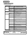
3.1.2 DM-LS121T specifications
LCD
Backlight
Item
Size
Type
Resolution
Color
Numbers of backlight
Brightness
Touch panel
Method
Surface solidity
Positioning accuracy
Interface connector
Indicator
Power supply
Case color
Others
TITLE
EPSON
Specification
12.1 inch
Color TFT
800 × 600 dots
256K color
2 lights
350 cd/m2 typ. (except touch panel)
290 cd/m2 typ. (including touch panel)
Resistive film (touch with finger)
2H or more (JIS K-5400)
±5 mm maximum
1 port for DM-MS123/112
POWER LED, HDD LED
+3.3V, +5V, +12V (Supplied from the IM-600)
Epson dark gray, Epson cool white
Connecting to the IM-600 through an exclusive cable.
Possible to adjust the LCD contrast with two adjustment
buttons on the left-side of the panel.
SR-600
Specification
(STANDARD)
SHEET
REVISION
A
NO.
NEXT
SHEET
4
3
Confidential
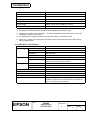
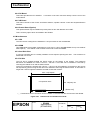
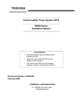
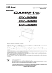
3.2 External Dimensions
310 (W) × 363 (D) × 277 (H) mm (including rubber feet, excluding LCD clamp)
Figure 3.2.1
TITLE
EPSON
DM-LS121T overall dimensions
SR-600
Specification
(STANDARD)
SHEET
REVISION
A
NO.
NEXT
SHEET
5
4
Confidential
3.3 EMI and Safety Standards Applied
3.3.1 For North America
EMI:
FCC class A
Safety standard:
UL1950
CSA C22.2 No.950
3.3.2 For Europe
CE marking:
EMC:
EN55022 class A
EN61000-3-2
EN61000-3-3
EN55024
IEC61000-4-2
IEC61000-4-3
IEC61000-4-4
IEC61000-4-5
IEC61000-4-6
IEC61000-4-11
Safety:
EN60950
This device can be damaged by surges induced by nearby electrical storms when connected
directly to an external aerial LAN cable. Therefore, the terminal should be connected only through
an appropriate surge suppressor when connection to such a cable is necessary. Otherwise, such
connection should be avoided.
3.3.3 For Japan
EMC:
VCCI class A
Harmonic current control guideline of Japan
JEIDA52
3.3.4 For other countries
Oceania EMC:
C-Tick marking
AS/NZS 3548 (CISPR22) Class
Taiwan EMI
Korea EMC
China EMC
TITLE
EPSON
SR-600
Specification
(STANDARD)
SHEET
REVISION
A
NO.
NEXT
SHEET
6
5
Confidential
3.4 Environmental Specifications
3.4.1 Temperature
Operating:
5 to 35°C
Storage:
-10 to 50°C
3.4.2 Humidity
Operating:
30 to 80% RH (no condensation)
Storage:
30 to 85% RH (no condensation)
3.4.3 Vibration resistance
When packed:
Frequency:
10 to 150 Hz
Acceleration:
19.6 m/s {2 G}
Sweep:
10 minutes (half cycle)
Duration:
1 hour
Directions:
x, y, and z
2
No external or internal damage should be found after the vibration test, and the unit should
operate normally. The test does not include options.
When unpacked and operating:
Frequency:
10 to 150 Hz
Acceleration:
4.9 m/s {0.5 G}
Sweep:
10 minutes (half cycle)
Duration:
1 hour
Directions:
x, y, and z
2
No external or internal damage should be found after the vibration test when operating, and
the unit should operate normally. The test does not include options.
3.4.4 Impact resistance
When packed:
Packing specifications:
EPSON standard packing
Height:
40 cm
Directions:
1 corner, 3 edges, 6 faces
No external or internal damage should be found after the drop test, and the unit should
operate normally.
When unpacked:
Height:
3 cm
Directions:
4 sides; lift one edge and release it
No external or internal damage should be found after the drop test (performed when the unit is
not operating), and the unit should operate normally.
TITLE
EPSON
SR-600
Specification
(STANDARD)
SHEET
REVISION
A
NO.
NEXT
SHEET
7
6
Confidential
3.5 Reliability
3.5.1 MTBF
33,000 hours (except HDD, fan)
3.5.2 Life
1) Cooling fan (IM-600)
CPU fan:
Power supply fan:
40,000 hours
27,000 hours
2) Hard Disk Drive (IM-600)
5 years or 20,000 hours, whichever comes first, with a maximum of 300,000 times of accessing the
drive.
3) Cold cathode fluorescent tube for backlight (DM-LS121T)
40,000 hours or more (at 25 ± 5°C)
Life is defined as when a brightness becomes a half-value.
This cold cathode fluorescent tube is changeable.
4) Durability of touch panel (DM-LS121T)
1) Durability by finger-input strokes:
10 million times or more
Condition:
Strokes one point by the material of the silicon gum (round of the tip: R8, solidity 60°), with
stroking load 1.96N {200gf}, for stroke cycle 5Hz.
2) Durability by pen-input writing:
1 million characters or more
Condition:
Writes optional alphanumeric or symbol characters which has the size of 7.5x 6.75 mm by the
material of the polyolefin plastic (round of the tip: R0.8), with writing load 3.43N {350gf} in the
area of 10x9 mm.
NOTE: Turning the power off when the IM-600 is not used will increase its life.
3.6 Power Consumption
The values below for the power consumption are given when the DM-LS121T is attached.
1) When the power is turned on but the HDD is not being accessed.
0.22 A
240 V
0.50 A
100 V
2) During the power on suspend
0.12 A
240 V
0.23 A
100 V
TITLE
EPSON
SR-600
Specification
(STANDARD)
SHEET
REVISION
A
NO.
NEXT
SHEET
8
7
Confidential
3.7 Power Supply
3.7.1 Power supply capacity to external devices
Total power available to devices connected to the interface boards (PCI slots, COM1 and 2 ports,
keyboard/mouse, customer display, and the USB ports) is as follows. Current drain must not exceed
the capacity shown for each supply voltage: +5, +3.3, +12, –12 and +24 volts.
Power Supply
+5 VDC
Table 3.1 Power Supply Capacities
Used for
PCI slots, COM ports, keyboard, FDD, USB
Capacity
2.5 A
+3.3 VDC
PCI slots
0.5 A
+12 VDC
PCI slots, DMD
0.7 A
–12 VDC
PCI slots
0.25 A
+24 VDC
Cash drawer
0.5 A, peak 2.0 A
Each port has the following current limitation:
USB port
Table 3.2 Power Supply Capacities for Each Port
Voltage
Current Supply Capacity
Remarks
Total current at +5 VDC
+5 VDC
400 mA each
must not exceed 2.5 A
+5 VDC
500 mA each
Keyboard
+5 VDC
500 mA
PCI slots
+5 VDC
1A
FDD
+5 VDC
500 mA
PCI slots
+12 VDC
500 mA
DMD
+12 VDC
600 mA
Port
COM port
Total current at +12 VDC
must not exceed 700 mA
3.7.2 Lithium rechargeable battery
The Bacchus is internally equipped with a vanadium-lithium rechargeable battery, which supplies the
backup voltage to the RTC, the RTC’s built-in CMOS RAM.
Charging period:
40 hours or more
Backup time:
200 days or more
WARNING: Don’t attempt to open or disassemble the Vanadium-lithium battery, which could result
in burns or release of hazardous chemicals.
Don’t charge or leave the vanadium-lithium battery in a hot place, such as near a fire or
on a heater, as it could overheat and ignite.
When you dispose of the vanadium-lithium battery, insulate it by wrapping the terminals
with tape. Do not mix with other metals or batteries; this may lead to fire, heat, or
explosion.
Vanadium-lithium batteries are not charged fully on delivery from the factory.
As a result, BIOS may display ‘cmos check sum error’.
TITLE
EPSON
SR-600
Specification
(STANDARD)
SHEET
REVISION
A
NO.
NEXT
SHEET
9
8
Confidential
4. BASE UNIT STRUCTURE
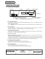
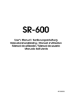
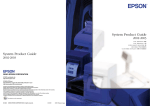
4.1 Terminal Front Panel (IM-600)
KB/Mouse
Reset Switch
CD-ROM Eject Button
CD-ROM LED
Front Cover Lock
Front Power Switch
Figure 4.1
Floppy Disk Drive Connector
Speaker Volume Control
Front Panel Controls & Connectors
4.1.1 Front Power Switch
This pushbutton switch at the lower left switches between power on and off. The switch is covered to
prevent inadvertent operation.
NOTE: Some operating systems might shut the power down automatically when the operating system
shuts off.
4.1.2 Reset Switch
Like the Power switch, this switch is behind a cover at lower left side of the front panel.
resets the entire system. A pointed implement is required to press the switch.
This switch
4.1.3 Speaker Volume Control
Like the Power and Reset switches, the speaker volume control at the lower left of the front panel is
also covered. Turning it to the right increases volume.
4.1.4 Front Cover Lock
This lock secures the large cover at the front right side of the terminal.
CD-ROM or CompactFlash from theft.
Locking this cover secures the
This lock operates in conjunction with the terminal cover lock, so that when the front cover is locked,
the terminal cover is also locked. The terminal cover locks in such a way that it cannot be opened with
a screwdriver, thus also securing the hard drive and other internal components from theft.
4.1.5 Floppy Disk Drive Connector
An external 3.5-inch floppy disk drive can be connected here.
Power should be turned off before connecting or disconnecting the drive.
4.1.6 Keyboard/mouse
A PS/2 compatible keyboard/mouse interface is provided.
Use a Y cable when the keyboard and mouse are used simultaneously.
TITLE
EPSON
SR-600
Specification
(STANDARD)
SHEET
REVISION
A
NO.
NEXT
SHEET
10
9
Confidential
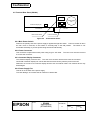
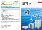
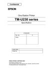
4.2 Terminal Rear Panel (IM-600)
O
|
Power Supply
Fan
Customer Display I/F
PCI Slot
I/O Interface
Main Power Switch
Figure 4.2
Power Connector
Terminal Rear Panel
4.2.1 Main Power Switch
Power to the primary side of the power supply is applied through this switch. Power is turned off when
the rear cover is removed, so this switch is normally kept in the ON position. The switch is not
accessible externally, to prevent power being turned off inadvertently.
4.2.2 Power Connector
This connector accepts external AC power using a type-L AC cable.
to access the connector.
The rear cover must be removed
4.2.3 Customer Display Connector
The customer display connects here. The rear cover must be removed to access the connector.
CAUTION: Customer display unit can be attached and removed only with the power turned off.
Please do not connect non-customer display devices such as network cable. The network device may
be damaged.
4.2.4 Power Supply Fan
This fan is on the back of the power supply.
To avoid damage, do not allow the fan outlet to be obstructed.
TITLE
EPSON
SR-600
Specification
(STANDARD)
SHEET
REVISION
A
NO.
NEXT
SHEET
11
10
Confidential
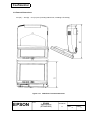
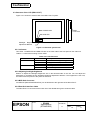
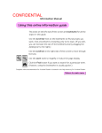
4.3 Structure of the LCD (DM-LS121T)
Figure 4.3.1 shows an external view of the DM-LS121T system.
POWER LED
MSR
connector
HDD LED
Backlight Brightness
adjustment Buttons
Figure 4.3.1 External system view
4.3.1 Indicators
Two LEDs - POWER LED and HDD LED are on the lower side of the front panel on the main unit.
Table 4.3.1 shows the meaning of each LEDs.
LED
POWER
HDD
Table 4.3.1 LED functions
Color
Meaning when lit
Green
Power is turned on (operating)
Orange
During power-on suspend
Off
Power is turned off.
Green
Accessing
Off
Not accessing
4.3.2 Adjusting backlight brightness
Buttons to adjust the backlight brightness are on the left-hand side of the unit. You can adjust the
brightness by operating the two backlight brightness adjustment buttons. If the brightness is set once,
the same level is kept even if the power is turned off.
4.3.3 MSR Unit Connector
An MSR unit (DM-MS123/DM-MS112) can be attached to the right side of the DM-LS121T.
4.3.4 Base Unit Interface Cable
The DM-LS121T is connected to the base unit of the IM-600 through the exclusive cable.
TITLE
EPSON
SR-600
Specification
(STANDARD)
SHEET
REVISION
A
NO.
NEXT
SHEET
12
11
Confidential
4.4 Circuit Board Configuration (IM-600)
Video Board
Motherboard
Figure 4.4.1
Circuit Board Configuration (top)
Drawer Board
VR Board
PCI Board
I/O Board
Figure 4.4.2
Circuit Board Configuration (bottom)
4.4.1 Motherboard
The motherboard provides basic PC functions, and consists of the CPU, chip set, memory (DIMM),
Super I/O and power circuitry.
4.4.2 Video Board
This board consists of the video controller and a connector for the LCD cable.
4.4.3 I/O Board
This board provides the connectors for most external devices. It is located on the bottom of the
terminal, and connects via its own connector directly near the rear of the motherboard. Connectors
are provided for three serial ports, one parallel port, two USB ports and one LAN port.
TITLE
EPSON
SR-600
Specification
(STANDARD)
SHEET
REVISION
A
NO.
NEXT
SHEET
13
12
Confidential
4.4.4 PCI Board
This board provides the PCI interface.
motherboard.
It connects via its own connector directly near the rear of the
4.4.5 VR Board
This board consists of the Power and Reset switches, speaker volume control and keyboard/mouse
interface.
4.4.6 Drawer Board (Option)
This optional board may be installed to provide ports for two cash drawers and a CRT.
This is a factory option which is installed in the SR-600.
4.5 Miscellaneous
4.5.1 CPU
The CPU and its cooling fan are installed in a 370-pin socket on the motherboard.
4.5.2 DIMM
Two DIMM slots are provided, supporting up to two 32, 64, 128 or 256-MB DIMMs for up to 512 MB of
RAM capacity. The cabinet cover must be removed to access the DIMMs.
4.5.3 Hard Disk Drive
A 2.5-inch hard disk drive is normally installed. Access requires opening the case.
affixed with one screw.
The hard drive is
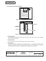
4.5.4 PCI Slot
The PCI slot is located beneath the power supply on the bottom of the chassis. The maximum
dimension of installable PCI card is 170 mm × 105 mm. A PCI card can be installed or removed by
removing the cabinet cover and the bottom frame.
Or the PCI card which is smaller than 145 mm × 105 mm can be installed or removed from the access
slot exposed by just removing the PCI slot cover instead of removing the bottom frame. A card which is
longer than 145mm might be installed if it’s width is less than 105mm.
Max. 170(145)mm
<Component side>
Max. 105(105) mm
[Units: mm]
(
) : Dimensions of PCI slot which can be installed or removed from the access slot of the IM-600.
Figure 4.5.1
TITLE
EPSON
Dimensions of Installable PCI Cards
SR-600
Specification
(STANDARD)
SHEET
REVISION
A
NO.
NEXT
SHEET
14
13
Confidential
4.6 Cautions
1. Cut edges of the metal case can become corroded depending on storage and operating conditions.
2. The AC cable must removed from the unit before
(1) Replacing the CPU, hard drive, DIMMs and other internal devices.
(2) Attaching or detaching options such as MSR, customer display and FDD.
(3) Connecting or disconnecting the devices such as TM printers, barcode scanners and
keyboard.
TITLE
EPSON
SR-600
Specification
(STANDARD)
SHEET
REVISION
A
NO.
NEXT
SHEET
15
14
Confidential
5. SOFTWARE SPECIFICATIONS
5.1 Available operating systems
We are considering providing localized language support for the following operating systems:
1)
2)
3)
4)
5)
®
Windows 95
®
Windows 98
®
Windows NT Workstation 4.0
®
MS-DOS 6.2
®
Windows 2000
5.2 Available Driver Software
1)
2)
3)
4)
®
®
Video driver (for Windows 95/98 or for Windows NT 4.0)
®
®
®
Touch panel driver (for Windows 95/98 or for Windows NT 4.0 or for DOS or Windows 2000)
®
®
Network driver (for Windows 95/98 or for Windows NT 4.0 or for DOS)
®
CD-ROM driver (for MS-DOS )
5.3 Available Tools
1) BIOS update tool
This is a tool to rewrite the BIOS when the BIOS needs to be updated.
2) MSR firmware update tool
This is a tool to rewrite the BIOS when the BIOS needs to be updated.
5.4 Available utilities
1) MSR set up utility
Program to set the MSR condition.
2) Device Diagnostics
Program to check each interface (included within the BIOS ROM)
®
®
®
3) Touch panel calibration (for Windows 95/98 or for Windows NT 4.0 or for DOS or Windows
2000)
This is a program to calibrate the touch panel.
®
®
4) Login utility for Windows 95/98, or for Windows NT
®
®
This is a utility to login to Windows 95/98 or Windows NT 4.0 without the keyboard unit.
5.5 OPOS
Recommended version:
TITLE
EPSON
Version 1.95 or later
SR-600
Specification
(STANDARD)
SHEET
REVISION
A
NO.
NEXT
SHEET
16
15
Confidential
6. OPTIONS
6.1 Factory Options
Options below are installed in the IM-600 before shipping.
IM-600.
1) CD-ROM drive unit
Model
Specify the options when purchasing the
Key Specifications
OI-S02
Thin-profile CD-ROM drive unit
IDE interface
With Eject button and access lamp
NOTE: The CD-ROM drive might be damaged if you adjust the LCD angle when CD-ROM drive is
open. The CD-ROM must be closed when you adjust the LCD angle.
2) Drawer Board
Cash drawer and external CRT interfaces are provided on a single board. By installing this board, a
cash drawer can be controlled independently of the TM printer, and a CRT can be used.
Model
Key Specifications
OI-B08
Two cash drawer ports
One external CRT port
NOTE: OPOS ver. 1.95 does not support the two drawers since the OPOS cannot know each drawer
status simultaneously.
3) CompactFlash Board
This board is required to use a CompactFlash card, which can be installed in place of either the hard
drive or CD-ROM drive.
Two types of connector boards are planned: one for use where a CompactFlash card would replace
the CD-ROM, and be accessible for replacement and removal from the front panel. This board could
be installed only in the CD-ROM location (not the hard drive location).
Model
Key Specifications
OI-S03-012
Board to enable using CompactFlash Card instead of CD-ROM drive.
OI-S03-022
Board to enable using CompactFlash Card instead of HDD.
NOTE: CompactFlash cards can be inserted and removed only with the power turned off. Doing so
with the power on could corrupt data stored on the card.
TITLE
EPSON
SR-600
Specification
(STANDARD)
SHEET
REVISION
A
NO.
NEXT
SHEET
17
16
Confidential
6.2 User Options
Options below are not installed in the IM-600 before shipping. They may be purchased independently.
1) MSR Units
Two types of MSR are available: one for Japan and one for overseas markets. The card slot is
angled 20° from the plane of the LCD to allow easy access. Installation entails removing the
connector cover on the right side of the LCD unit (DM-LS121T), and affixing the MSR unit with two
screws.
Model
Key Specification
DM-MS123
ISO Tracks 1, 2, and 3 compatible (for overseas)
DM-MS112
JIS II, Tracks 1 and 2 compatible (for Japan)
NOTE: MSR can be installed and uninstalled only with the power turned off. The connector cover
should be installed even when no MSR unit is installed.
2) Customer Display Units
A special DM holder (attached) at the center of the rear of the terminal is used for installation.
The customer display port is on the motherboard at the rear of the terminal.
The following model of the Epson customer display can be used.
Model
Key Specifications
DM-D110
20-character × 2-line display
NOTE: Customer display unit can be attached and removed only with the power turned off.
3) Floppy disk drive units
An optional external 3.5-inch floppy disk drive can be connected for installing maintenance software.
The interface connector is at the right side of the front panel of the terminal.
Model
Key Specifications
OI-S01
External floppy disk drive
3.5-inch, 720 KB/1.44 MB
NOTE: Floppy disk drive unit can be connected and disconnected only with the power turned off.
6.3 Precautions Related to Internal Components
1. CPU, DIMM, HDD
EPSON quality assuer the assembled CPU, DIMM and HDD in IM-600 under the EPSON shipping
condition.
In case a customer exchange CPU, DIMM and HDD, EPSON quality assure only for CPU, DIMM
and HDD which are purchased from EPSON.
2. Interfaces and expansion slot
EPSON guarantee that each interfaces(include the compact flash interface) and PCI expansion
slot are in conformity to each interface standards.
When customer use any equipment and/or any PCI boards connected to IM-600, please check
those functions with IM-600 by yourself. Please refer to the "EPSON Operational testing products
list" for your selection of any equipment and/or any PCI boards.
TITLE
EPSON
SR-600
Specification
(STANDARD)
SHEET
REVISION
A
NO.
NEXT
END
18
SHEET
17