1
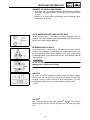
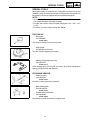
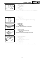
Cover_SMB.fm Page 1 Thursday, July 27, 2006 9:56 AM
SERVICE MANUAL
PZ50W
PZ50GTW
PZ50FXW
PZ50MW
PZ50VTW
PZ50MPW
YAMAHA MOTOR CO., LTD.
PRINTED ON RECYCLED PAPER
PRINTED IN U.S.A.
2006.07 CR
(E)
LIT-12618-02-58
8GC-28197-10
NOTICE
This manual was written by the Yamaha Motor
Company primarily for use by Yamaha dealers and
their qualified mechanics. It is not possible to put an
entire mechanic’s education into one manual, so it
is assumed that persons using this book to perform
maintenance and repairs on Yamaha snowmobiles
have a basic understanding of the mechanical concepts and procedures inherent in snowmobile
repair. Without such knowledge, attempted repairs
or service to this model may render it unfit and/or
unsafe to use. Yamaha Motor Company, Ltd. is
continually striving to improve all models manufactured by Yamaha. Modifications and significant
changes in specifications or procedures will be forwarded to all authorized Yamaha dealers and will,
where applicable, appear in future editions of this
manual.
HOW TO USE THIS MANUAL
Particularly important information is distinguished in
this manual by the following notations:
The Safety Alert Symbol means ATTENTION! BE
ALERT! YOUR SAFETY IS INVOLVED!
WARNING
Failure to follow WARNING instructions could result
in severe injury or death to the snowmobile operator, a bystander, or a person inspecting or repairing
the snowmobile.
CAUTION:
A CAUTION indicates special precautions that
must be taken to avoid damage to the snowmobile.
NOTE:
A NOTE provides key information that can make
procedures easier or clearer.
MANUAL FORMAT
All of the procedures in this manual are organized
in a sequential, step-by-step format. The information has been compiled to provide the mechanic
with an easy to read, handy reference that contains
comprehensive explanations of all inspection,
repair, assembly, and disassembly operations.
In this revised format, the condition of a faulty component will precede an arrow symbol and the
course of action required to correct the problem will
follow the symbol, e.g.,
• Bearings
Pitting/damage → Replace.
EXPLODED DIAGRAM
PZ50W, PZ50GTW, PZ50FXW, PZ50MW,
PZ50VTW, PZ50MPW
SERVICE MANUAL
©2006 by Yamaha Motor
Corporation, U.S.A.
1st Edition, July 2006
All rights reserved. Any reprinting or
unauthorized use without the written
permission of Yamaha Motor Corporation,
U.S.A. is expressly prohibited.
Printed in U.S.A.
P/N.LIT-12618-02-58
Each chapter provides exploded diagrams before
each disassembly section to facilitate correct disassembly and assembly procedures.
1
ILLUSTRATED SYMBOLS
(Refer to the illustration)
2
INSP
ADJ
GEN
INFO
3
Illustrated symbols 1 to 9 are designed as thumb
tabs to indicate the chapter’s number and content.
4
1
2
3
4
5
6
7
8
9
POWR
TR
CHAS
5
6
COOL
ENG
7
General information
Periodic inspection and adjustment
Chassis
Power train
Engine
Cooling system
Fuel injection system
Electrical
Specifications
8
FI
ELEC
–
+
9
SPEC
0
A
Illustrated symbols 0 to F are used to identify the
specifications which appear.
B
T.
R.
C
D
E
F
G
H
5
LT
I
J
G
E
L
K
M
B
O
New
M
N
LS
M
0
A
B
C
D
E
F
Filling fluid
Lubricant
Tightening
Wear limit, clearance
Engine speed
Special tool
Ω, V, A
Illustrated symbols G to O in the exploded diagram
indicate grade of lubricant and location of lubrication point.
G
H
I
J
K
L
M
N
O
Apply locking agent (LOCTITE®)
Apply Yamabond No.5®
Apply engine oil
Apply gear oil
Apply molybdenum disulfide oil
Apply wheel bearing grease
Apply low-temperature lithium-soap base grease
Apply molybdenum disulfide grease
Use new one
INDEX
GENERAL INFORMATION
PERIODIC INSPECTION AND
ADJUSTMENT
CHASSIS
POWER TRAIN
ENGINE
COOLING SYSTEM
FUEL INJECTION SYSTEM
GEN
INFO
1
INSP
ADJ
2
CHAS
3
POWR
TR
4
ENG
5
COOL
6
FI
7
–
ELECTRICAL
SPECIFICATIONS
+
ELEC
8
SPEC
9
CHAPTER 1.
GENERAL INFORMATION
MACHINE IDENTIFICATION............................ 1-1
FRAME SERIAL NUMBER ......................... 1-1
ENGINE SERIAL NUMBER........................ 1-1
IMPORTANT INFORMATION .......................... 1-2
PREPARATION FOR REMOVAL AND
DISASSEMBLY........................................... 1-2
ALL REPLACEMENT PARTS..................... 1-2
GASKETS, OIL SEALS, AND O-RINGS..... 1-3
LOCK WASHERS/PLATES AND COTTER
PINS............................................................ 1-3
BEARINGS AND OIL SEALS ..................... 1-3
CIRCLIPS ................................................... 1-3
LOCTITE® ................................................... 1-3
SPECIAL TOOLS ............................................. 1-4
FOR TUNE UP............................................ 1-4
FOR ENGINE SERVICE............................. 1-4
FOR POWER TRAIN SERVICE ................. 1-7
FOR FUEL INJECTION SERVICE ............. 1-8
FOR ELECTRICAL SERVICE .................... 1-8
CHAPTER 2.
PERIODIC INSPECTION
AND ADJUSTMENT
INTRODUCTION............................................... 2-1
PERIODIC MAINTENANCE CHART FOR
THE EMISSION CONTROL SYSTEM.............. 2-1
GENERAL MAINTENANCE AND
LUBRICATION CHART.................................... 2-2
ENGINE ............................................................ 2-4
SPARK PLUGS........................................... 2-4
FUEL LINE INSPECTION........................... 2-4
COOLING SYSTEM.................................... 2-5
VALVE CLEARANCE ADJUSTMENT ........ 2-7
THROTTLE BODY
SYNCHRONIZATION ............................... 2-13
ENGINE IDLE SPEED ADJUSTMENT..... 2-14
THROTTLE CABLE FREE PLAY
ADJUSTMENT.......................................... 2-15
THROTTLE OVERRIDE SYSTEM
(T.O.R.S.) CHECK .................................... 2-16
COMPRESSION PRESSURE
MEASUREMENT ...................................... 2-17
ENGINE OIL LEVEL INSPECTION .......... 2-19
ENGINE OIL REPLACEMENT ................. 2-20
CYLINDER HEAD BREATHER HOSE
INSPECTION ............................................ 2-23
THROTTLE BODY JOINTS
INSPECTION ............................................ 2-23
CHECKING THE AIR FILTER
ELEMENT ................................................. 2-24
EXHAUST SYSTEM INSPECTION .......... 2-25
POWER TRAIN............................................... 2-26
SHEAVE OFFSET ADJUSTMENT ........... 2-26
DRIVE V-BELT.......................................... 2-28
ENGAGEMENT SPEED CHECK.............. 2-29
PARKING BRAKE ADJUSTMENT............ 2-29
BRAKE FLUID LEVEL INSPECTION ....... 2-30
BRAKE PAD INSPECTION....................... 2-31
BRAKE HOSE INSPECTION.................... 2-32
AIR BLEEDING (HYDRAULIC BRAKE
SYSTEM) .................................................. 2-32
DRIVE CHAIN ........................................... 2-33
TRACK TENSION ADJUSTMENT............ 2-35
SLIDE RUNNER INSPECTION ................ 2-37
MAXIMIZING DRIVE TRACK LIFE ........... 2-37
CHASSIS ........................................................ 2-39
SKI/SKI RUNNER ..................................... 2-39
STEERING SYSTEM ................................ 2-39
LUBRICATION .......................................... 2-41
ELECTRICAL ................................................. 2-42
HEADLIGHT BEAM ADJUSTMENT ......... 2-42
BATTERY INSPECTION........................... 2-42
FUSE INSPECTION.................................. 2-48
TUNING .......................................................... 2-50
CLUTCH.................................................... 2-50
GEAR SELECTION................................... 2-55
FRONT SUSPENSION ............................. 2-61
REAR SUSPENSION................................ 2-63
CHAPTER 3.
CHASSIS
COWLINGS ...................................................... 3-1
PZ50/PZ50GT/PZ50FX/PZ50M .................. 3-1
PZ50VT/PZ50MP ........................................ 3-3
STEERING ........................................................ 3-4
PZ50W/PZ50GT/PZ50FX/PZ50M............... 3-4
PZ50VT/PZ50MP ........................................ 3-6
REMOVAL................................................. 3-10
INSPECTION ............................................ 3-10
INSTALLATION......................................... 3-11
SKI .................................................................. 3-14
PZ50/PZ50GT/PZ50FX/PZ50VT “USA/
Canada” .................................................... 3-14
PZ50VT “Europe”/PZ50MP....................... 3-15
PZ50M ...................................................... 3-16
INSPECTION ............................................ 3-17
FRONT SUSPENSION ................................... 3-18
PZ50/PZ50FX/PZ50M............................... 3-18
PZ50GT/PZ50VT/PZ50MP ....................... 3-20
HANDLING NOTES .................................. 3-22
INSPECTION ............................................ 3-22
INSTALLATION ........................................ 3-23
CHAPTER 4.
POWER TRAIN
PRIMARY SHEAVE AND DRIVE V-BELT ....... 4-1
REMOVAL .................................................. 4-3
DISASSEMBLY........................................... 4-3
INSPECTION .............................................. 4-4
ASSEMBLY................................................. 4-6
INSTALLATION .......................................... 4-9
SECONDARY SHEAVE ................................. 4-10
DISASSEMBLY......................................... 4-12
INSPECTION ............................................ 4-12
ASSEMBLY............................................... 4-13
INSTALLATION ........................................ 4-14
DRIVE CHAIN................................................. 4-15
REMOVAL ................................................ 4-16
INSPECTION ............................................ 4-16
INSTALLATION ........................................ 4-18
SECONDARY SHAFT .................................... 4-19
PZ50 ......................................................... 4-19
REMOVAL ................................................ 4-20
INSPECTION ............................................ 4-20
INSTALLATION ........................................ 4-20
SECONDARY SHAFT AND DRIVE
CHAIN INSTALLATION ............................ 4-22
SECONDARY SHAFT AND REVERSE
GEAR CASE................................................... 4-23
PZ50GT/PZ50FX/PZ50M/PZ50VT/
PZ50MP .................................................... 4-23
REMOVAL ................................................ 4-27
INSPECTION ............................................ 4-28
ASSEMBLY............................................... 4-28
INSTALLATION ........................................ 4-29
SECONDARY SHAFT AND DRIVE
CHAIN INSTALLATION ............................ 4-30
BRAKE ........................................................... 4-31
BRAKE PAD REPLACEMENT ................. 4-33
BRAKE CALIPER DISASSEMBLY ........... 4-36
BRAKE CALIPER INSPECTION
AND REPAIR ............................................ 4-36
BRAKE CALIPER ASSEMBLY ................. 4-37
BRAKE CALIPER INSTALLATION ........... 4-37
INSPECTION ............................................ 4-39
BRAKE MASTER CYLINDER
ASSEMBLY............................................... 4-39
INSTALLATION......................................... 4-39
SLIDE RAIL SUSPENSION............................ 4-40
PZ50/PZ50GT/PZ50FX/PZ50M ................ 4-40
PZ50VT/PZ50MP ...................................... 4-45
REMOVAL................................................. 4-51
INSPECTION ............................................ 4-51
ASSEMBLY............................................... 4-51
INSTALLATION......................................... 4-55
FRONT AXLE AND TRACK ........................... 4-56
INSPECTION ............................................ 4-57
INSTALLATION......................................... 4-57
CHAPTER 5.
ENGINE
SEAT AND FUEL TANK................................... 5-1
PZ50/PZ50GT/PZ50FX/PZ50M .................. 5-1
BACKREST AND PASSENGER SEAT ........... 5-3
PZ50VT/PZ50MP ........................................ 5-3
RIDER SEAT AND FUEL TANK ...................... 5-5
PZ50VT/PZ50MP ........................................ 5-5
REMOVAL................................................... 5-7
INSTALLATION........................................... 5-8
EXHAUST PIPE AND MUFFLER ..................... 5-9
PZ50/PZ50GT/PZ50FX/PZ50M .................. 5-9
PZ50VT/PZ50MP ...................................... 5-10
INSTALLATION......................................... 5-11
OIL TANK ....................................................... 5-12
ENGINE ASSEMBLY ..................................... 5-13
HOSE AND LEADS................................... 5-13
ENGINE ASSEMBLY ................................ 5-15
REMOVAL................................................. 5-16
INSTALLATION......................................... 5-16
CAMSHAFTS.................................................. 5-18
CYLINDER HEAD COVER ....................... 5-18
CAMSHAFTS ............................................ 5-19
REMOVAL................................................. 5-20
INSPECTION ............................................ 5-21
INSTALLATION......................................... 5-25
CYLINDER HEAD........................................... 5-28
REMOVAL ................................................ 5-29
INSPECTION ............................................ 5-29
INSTALLATION ........................................ 5-30
VALVES AND VALVE SPRINGS................... 5-32
REMOVAL ................................................ 5-33
INSPECTION ............................................ 5-34
INSTALLATION ........................................ 5-38
A.C. MAGNETO ROTOR AND STARTER
CLUTCH ......................................................... 5-41
REMOVAL ................................................ 5-42
INSPECTION ............................................ 5-43
INSTALLATION ........................................ 5-44
OIL PAN AND OIL PUMP .............................. 5-46
REMOVAL ................................................ 5-49
INSPECTION ............................................ 5-49
INSTALLATION ........................................ 5-50
BALANCER .................................................... 5-52
REMOVAL ................................................ 5-54
INSPECTION ............................................ 5-55
INSTALLATION ........................................ 5-55
CRANKCASE ................................................. 5-58
CRANKCASE............................................ 5-58
CONNECTING RODS AND PISTONS ..... 5-59
CRANKSHAFT.......................................... 5-60
REMOVAL ................................................ 5-61
INSPECTION ............................................ 5-63
INSTALLATION ........................................ 5-74
CHAPTER 6.
COOLING SYSTEM
RADIATOR AND HEAT EXCHANGER............ 6-1
INSPECTION .............................................. 6-3
INSTALLATION .......................................... 6-4
THERMOSTAT ................................................. 6-5
INSPECTION .............................................. 6-6
INSTALLATION .......................................... 6-6
WATER PUMP.................................................. 6-8
DISASSEMBLY......................................... 6-10
INSPECTION ............................................ 6-10
ASSEMBLY............................................... 6-11
INSTALLATION ........................................ 6-12
CHAPTER 7.
FUEL INJECTION SYSTEM
FUEL INJECTION SYSTEM ............................. 7-1
WIRING DIAGRAM ..................................... 7-2
ECU SELF-DIAGNOSTIC FUNCTION ....... 7-4
SELF-DIAGNOSTIC FUNCTION TABLE.... 7-4
TROUBLESHOOTING CHART................... 7-6
DIAGNOSTIC MODE .................................. 7-7
TROUBLESHOOTING DETAILS .............. 7-14
OIL PRESSURE SWITCH ........................ 7-28
INTAKE AIR TEMPERATURE
SENSOR ................................................... 7-28
THROTTLE BODY.......................................... 7-29
INJECTORS.............................................. 7-30
INSPECTION ............................................ 7-31
PRESSURE REGULATOR
OPERATION ............................................. 7-31
INSPECTION AND ADJUSTMENT .......... 7-32
CHAPTER 8.
ELECTRICAL
SWITCH INSPECTION ..................................... 8-1
SWITCH INSPECTION ............................... 8-1
INSPECTING A SWITCH SHOWN IN
THE MANUAL ............................................. 8-1
IGNITION SYSTEM .......................................... 8-2
CIRCUIT DIAGRAM.................................... 8-2
TROUBLESHOOTING ................................ 8-4
IGNITION SPARK GAP .............................. 8-6
IGNITION COIL........................................... 8-6
CRANKSHAFT POSITION SENSOR ......... 8-7
THROTTLE OVERRIDE SYSTEM
(T.O.R.S.).................................................... 8-8
ENGINE STOP SWITCH ............................ 8-9
THROTTLE SWITCH .................................. 8-9
MAIN SWITCH .......................................... 8-10
ELECTRICAL STARTING SYSTEM .............. 8-11
CIRCUIT DIAGRAM.................................. 8-11
TROUBLESHOOTING .............................. 8-12
STARTER MOTOR ................................... 8-14
CHARGING SYSTEM ..................................... 8-19
CIRCUIT DIAGRAM.................................. 8-19
TROUBLESHOOTING .............................. 8-20
BATTERY.................................................. 8-21
A.C. MAGNETO ........................................ 8-21
LIGHTING SYSTEM ....................................... 8-22
CIRCUIT DIAGRAM.................................. 8-22
TROUBLESHOOTING.............................. 8-24
BULB(S).................................................... 8-26
HEADLIGHT BEAM SWITCH ................... 8-26
HEADLIGHT RELAY................................. 8-27
LOAD CONTROL RELAY......................... 8-27
SIGNAL SYSTEM........................................... 8-28
CIRCUIT DIAGRAM.................................. 8-28
TROUBLESHOOTING.............................. 8-30
BRAKE LIGHT SWITCH ........................... 8-38
DRIVE POSITION SWITCH AND
REVERSE POSITION SWITCH
(PZ50GT/PZ50FX/PZ50M/PZ50VT/
PZ50MP)................................................... 8-38
DC BACK BUZZER (PZ50GT/PZ50FX/
PZ50M/PZ50VT/PZ50MP) ........................ 8-38
COOLANT TEMPERATURE SENSOR .... 8-39
OIL LEVEL SWITCH................................. 8-40
FUEL SENDER......................................... 8-40
SPEED SENSOR...................................... 8-41
KNOCK SENSOR ..................................... 8-41
GRIP WARMER SYSTEM .............................. 8-42
CIRCUIT DIAGRAM.................................. 8-42
TROUBLESHOOTING.............................. 8-44
GRIP AND THUMB WARMER ................. 8-46
GRIP/THUMB WARMER ADJUSTMENT
SWITCH.................................................... 8-46
PASSENGER GRIP WARMER
(PZ50VT) .................................................. 8-47
PASSENGER GRIP WARMER SWITCH
(PZ50VT) .................................................. 8-47
PASSENGER GRIP WARMER RELAY
(PZ50VT/PZ50MP) ................................... 8-48
COOLING SYSTEM
(PZ50M/PZ50VT/PZ50MP) ............................. 8-50
CIRCUIT DIAGRAM.................................. 8-50
TROUBLESHOOTING.............................. 8-52
RADIATOR FAN MOTOR......................... 8-53
RADIATOR FAN MOTOR RELAY ............ 8-53
DRIVE/REVERSE SELECTING SYSTEM
(PZ50GT/PZ50FX/PZ50M/PZ50VT/
PZ50MP) ......................................................... 8-54
CIRCUIT DIAGRAM.................................. 8-54
TROUBLESHOOTING.............................. 8-56
GEAR MOTOR ......................................... 8-57
GEAR MOTOR RELAY 1.......................... 8-58
GEAR MOTOR RELAY 2.......................... 8-58
GEAR MOTOR RELAY 3.......................... 8-59
CHAPTER 9.
SPECIFICATIONS
GENERAL SPECIFICATIONS.......................... 9-1
MAINTENANCE SPECIFICATIONS................. 9-5
ENGINE ...................................................... 9-5
POWER TRAIN......................................... 9-10
CHASSIS .................................................. 9-16
ELECTRICAL ............................................ 9-18
TIGHTENING TORQUE.................................. 9-21
ENGINE .................................................... 9-21
POWER TRAIN......................................... 9-23
CHASSIS .................................................. 9-25
GENERAL TORQUE SPECIFICATIONS ....... 9-27
DEFINITION OF UNITS .................................. 9-27
CABLE ROUTING .......................................... 9-29
MACHINE IDENTIFICATION
GEN
INFO
GENERAL INFORMATION
MACHINE IDENTIFICATION
FRAME SERIAL NUMBER
The frame serial number 1 is located on the right-hand side of the frame
(just below the front of the seat).
ENGINE SERIAL NUMBER
The engine serial number 1 is located on the left-hand side of the crankcase.
NOTE:
Designs and specifications are subject to change without notice.
1-1
IMPORTANT INFORMATION
GEN
INFO
IMPORTANT INFORMATION
PREPARATION FOR REMOVAL AND DISASSEMBLY
1. Remove all dirt, mud, dust, and foreign material before removal and
disassembly.
While cleaning, take care to protect the electrical parts, such as relays,
switches, motor, resistors, controllers, etc., from high pressure water
splashes.
2. Use proper tools and cleaning equipment.
Refer to “SPECIAL TOOLS”.
3. When disassembling the machine, keep mated parts together. This
includes gears, cylinders, pistons, and other parts that have been
“mated” through normal wear. Mated parts must be reused or replaced
as an assembly.
4. During disassembly of the machine, clean all parts and place them in
trays in the order of disassembly. This will speed up assembly time and
help ensure that all parts are reinstalled correctly.
5. Keep all parts away from any source of fire.
6. Be sure to keep to the tightening torque specifications. When tightening bolts, nuts, and screws, start with those that have larger diameters,
and proceed from the inside to the outside in a crisscross pattern.
ALL REPLACEMENT PARTS
We recommend using genuine Yamaha parts for all replacements. Use oil
and grease recommended by Yamaha for assembly and adjustments.
1-2
1
IMPORTANT INFORMATION
GEN
INFO
GASKETS, OIL SEALS, AND O-RINGS
1. All gaskets, seals, and O-rings should be replaced when an engine is
overhauled. All gasket surfaces, oil seal lips, and O-rings must be
cleaned.
2. Properly oil all mating parts and bearings during reassembly. Apply
grease to the oil seal lips.
LOCK WASHERS/PLATES AND COTTER PINS
All lock washers/plates 1 and cotter pins must be replaced if they are
removed. Lock tab(s) should be bent along the bolt or nut flat(s) after the
bolt or nut has been properly tightened.
BEARINGS AND OIL SEALS
Install the bearings 1 and oil seals 2 with their manufacturer’s marks or
numbers facing outwards. (In other words, the stamped letters must be on
the side exposed to view.) When installing oil seals, apply a light coating
of lightweight lithium base grease to the seal lips. Oil the bearings liberally
when installing.
CAUTION:
Do not use compressed air to spin the bearings dry. This causes
damage to the surface of the bearings.
CIRCLIPS
All circlips should be inspected carefully before reassembly. Always
replace piston pin clips after one use. Replace misshapen circlips. When
installing a circlip 1, make sure that the sharp edged corner 2 is positioned opposite to the thrust 3 it receives. See the sectional view.
4 Shaft
LOCTITE®
After installing fasteners that have LOCTITE® applied, wait 24 hours
before using the machine. This will give the LOCTITE® time to dry properly.
1-3
SPECIAL TOOLS
GEN
INFO
SPECIAL TOOLS
Some special tools are necessary for a completely accurate tune-up and
assembly. Using the correct special tool will help prevent damage that can
be caused by the use of improper tools or improvised techniques.
NOTE:
• Be sure to use the correct part number when ordering the tool, since the
part number may differ according to country.
• For USA and Canada, use part number starting with “YB-”, “YM-”, “YU-”
or “YS-”.
• For others, use part number starting with “90890-”.
FOR TUNE UP
• Dial gauge
P/N: YU-03097
90890-03097
This gauge is used for run out measurement.
• Angle gauge
Use goods on the market.
This tool is used to tightening the torque.
• Steering linkage alignment plate
P/N: YS-01515
90890-01515
Locks steering relay arm and pivot arm shaft in place while adjusting the
steering linkage for front-end alignment.
FOR ENGINE SERVICE
• Piston pin puller
P/N: YU-01304
90890-01304
This tool is used to remove the piston pin.
• Rotor holding puller
P/N: YU-33270-B
90890-01362
• Flywheel puller attachment
P/N: YM-33282
90890-04089
These tools are used to remove the magneto rotor.
1-4
SPECIAL TOOLS
GEN
INFO
• Cooling system tester
P/N: YU-24460-01
90890-01325
• Adapter
P/N: YU-33984
90890-01352
This tester and its adapter are used for checking the cooling system.
• Oil filter wrench
P/N: YM-01469
90890-01469
This tool is needed to loosen or tighten the oil filter cartridge.
• Vacuum gauge
P/N: YU-44456
90890-03094
This guide is used to synchronize the carburetors.
• Compression gauge
P/N: YU-33223 (compression gage)
90890-03081
These tools are used to measure engine compression.
• Valve spring compressor
P/N: YM-04019
90890-04019
• Valve spring compressor attachment
P/N: YM-04108
90890-04108
P/N: YM-04114
90890-04114
These tools are used to remove or install the valve assemblies.
1-5
SPECIAL TOOLS
GEN
INFO
• 40 and 50 mm bearing driver
P/N: YM-04058
90890-04058
• Mechanical seal installer
P/N: YM-04145
90890-04145
These tools are used to install the water pump seal.
• Rotor holding tool
P/N: YU-01235
90890-01235
This tool is used to hold the camshaft sprocket.
• Valve guide remover (ø4)
P/N: YM-04111
90890-04111
This tool is used to remove or install the valve guides.
• Valve guide installer (ø4)
P/N: YM-04112
90890-04112
This tool is used to install the valve guides.
• Valve guide reamer (ø4)
P/N: YM-04113
90890-04113
This tool is used to rebore the new valve guides.
• Valve lapper
P/N: 90890-04101
This tool is needed to remove and install the valve lifters.
• Piston ring compressor
P/N: YM-08037
90890-05158
This tool is used to compress the piston rings when installing the piston
into the cylinder.
1-6
SPECIAL TOOLS
GEN
INFO
• Dynamic spark tester
P/N: YM-34487
• Ignition checker
P/N: 90890-06754
This tool is used to check the ignition system component.
• Engine mount spacer wrench
P/N: YS-01516
90890-01516
Used to turn the engine mounting bolts when removing/installing engine.
• Yamaha bond No. 1215
P/N: 90890-85505
(Three Bond No.1215®)
This bond is used to seal two mating surfaces (e.g., crankcase mating surfaces.)
FOR POWER TRAIN SERVICE
• Sheave holder
P/N: YS-01880-A
90890-01701
This tool is used to hold the primary sheave and A.C. magneto rotor.
• Primary sheave puller (18 mm)
P/N: YS-01881-A 1, YS-01881-1 2
90890-01898
This tool is used for removing the primary sheave.
• Clutch spider separator
P/N: YS-28890-C
90890-01711
This tool is used when disassembling and assembling the primary sheave.
• Clutch separator adapter
P/N: YS-34480
90890-01740
This tool is used when disassembling and assembling the primary sheave.
• YXR clutch bushing jig kit
P/N: YS-39752
This tool is used for removal and installation of primary clutch weight and
roller bushings.
1-7
SPECIAL TOOLS
GEN
INFO
• Clutch bushing press
P/N: YS-42424
This tool is used for removing and installing the post bushings (primary
sheave cap bush, sliding sheave bush and torque cam bush).
• Track clip installer
P/N: YS-91045-C
90890-01721
This tool is used for installing the track clip.
FOR FUEL INJECTION SERVICE
• Mity vac
P/N: YS-42423
90890-06756
This tool is used to measure the vacuum pressure.
• Fuel pressure adapter
P/N: YM-03176
90890-03176
This tool is needed to measure fuel pressure.
• Pressure gauge
P/N: YU-03153
90890-03153
This tool is used to measure fuel pressure.
• Vacuum gauge
P/N: YU-08030
90890-03094
This guide is used to synchronize the throttle bodies.
FOR ELECTRICAL SERVICE
• Pocket tester
P/N: YU-03112-C
90890-03112
This instrument is necessary for checking the electrical components.
• Engine tachometer
P/N: YU-08036-C
90793-80009
This tool is used to check engine speed.
1-8
SPECIAL TOOLS
GEN
INFO
• Digital circuit tester
P/N: YU-A1927
90890-03174
This instrument is necessary for checking the electrical componenets.
1-9
INTRODUCTION/PERIODIC MAINTENANCE CHART FOR
THE EMISSION CONTROL SYSTEM
INSP
ADJ
PERIODIC INSPECTION AND ADJUSTMENT
INTRODUCTION
This chapter includes all information necessary to perform recommended inspections and adjustments. These
preventive maintenance procedures, if followed, will ensure more reliable machine operation and a longer service life. In addition, the need for costly overhaul work will be greatly reduced. This information applies to
machines already in service as well as new machines that are being prepared for sale. All service technicians
should be familiar with this entire chapter.
PERIODIC MAINTENANCE CHART FOR THE EMISSION CONTROL SYSTEM
Item
Pre-operation check
(Daily)
Remarks
Spark plugs
Check condition.
Adjust gap and clean.
Replace if necessary.
∗ Valve clearance
Check clearance.
Adjust clearance when engine is cold.
∗ Crankcase breather system
Check breather hose for cracks or damage.
Replace if necessary.
∗ Fuel filter
Check condition.
Replace if necessary.
∗ Fuel line
Check fuel hose for cracks or damage.
Replace if necessary.
∗ Idle speed
Check and adjust engine idle speed.
∗ Fuel injection
Adjust synchronization.
∗ Exhaust system
Check for leakage.
Tighten or replace gasket if necessary.
∗ It is recommended that these items be serviced by a Yamaha dealer.
2-1
Initial
1 month or
800 km
(500 mi)
(40 hr)
Every 40,000 km (25,000 mi)
Every
Seasonally
or 4,000 km
(2,500 mi)
(200 hr)
2
GENERAL MAINTENANCE AND LUBRICATION CHART
INSP
ADJ
GENERAL MAINTENANCE AND LUBRICATION CHART
Item
Engine oil
∗ Engine oil filter cartridge
Fuel
Engine coolant
Pre-operation check
(Daily)
Remarks
Every
Seasonally
or 4,000 km
(2,500 mi)
(200 hr)
Check oil level.
∗ Replace.
Every
20,000 km
(12,000 mi)
Replace.
Check fuel level.
Check coolant level.
∗ Air bleed the cooling system if necessary.
Throttle lever (handlebar
side)
Check operation.
∗ Repair if necessary.
Throttle override system
(T.O.R.S.)
Check operation.
∗ Repair if necessary.
Engine stop switch
Check operation.
∗ Repair if necessary.
Drive guard
Check for cracks, bends or damage.
∗ Replace if necessary.
V-belt
Check for wear and damage.
Replace if necessary.
Drive track and idler wheels
Check deflection, and for wear and damage.
∗ Adjust/replace if necessary.
Slide runners
Initial
1 month or
800 km
(500 mi)
(40 hr)
Check for wear and damage.
∗ Replace if necessary.
Check operation and fluid leakage.
Brake and parking brake
∗ Adjust free play and/or replace pads if necessary.
∗ Replace brake fluid.
∗ Disc brake installation
Drive chain oil
Drive chain
Skis and ski runners
Steering system
See NOTE on page 2-3.
Check for slight free play.
Lubricate shaft with specified grease as required.
Check oil level.
∗ Replace.
Check deflection.
∗ Adjust if necessary.
Initial at 500 km (300 mi) and every 800 km
(500 mi) thereafter.
Check for wear and damage.
∗ Replace if necessary.
Check operation.
∗ Adjust toe-out if necessary.
Strap (PZ50M)
Check for damage.
∗ Replace if necessary.
Lights
Check operation.
Replace bulbs if necessary.
∗ Battery
Check condition.
Charge if necessary.
Check engagement and shift speed.
Adjust if necessary.
∗ Primary and secondary
clutches
Every
1,600 km
(1,000 mi)
Inspect sheaves for wear/damage.
Inspect weights/rollers and bushings for wear-for primary.
Inspect ramp shoes/bushings for wear-for secondary.
Replace if necessary.
Lubricate with specified grease.
∗ Steering column bearing
Lubricate with specified grease.
∗ Ski and front suspension
Lubricate with specified grease.
∗ It is recommended that these items be serviced by a Yamaha dealer.
2-2
Whenever operating elevation is changed.
GENERAL MAINTENANCE AND LUBRICATION CHART
Item
∗ Suspension component
Pre-operation check
(Daily)
Remarks
INSP
ADJ
Initial
1 month or
800 km
(500 mi)
(40 hr)
Every
Seasonally
or 4,000 km
(2,500 mi)
(200 hr)
Lubricate with specified grease.
Lubricate with specified grease.
∗ Parking brake cable end
and lever end/throttle cable Check cable damage.
end
Replace if necessary.
Shroud and covers
Make sure that the shroud and covers are securely fastened.
Fittings and fasteners
Check tightness.
∗ Repair if necessary.
Tool kit and recommended
equipment
Check for proper placement.
∗ It is recommended that these items be serviced by a Yamaha dealer.
NOTE:
@
Brake system:
• After disassembling the master cylinder or caliper cylinder, always change the brake fluid. Regularly check
the brake fluid level and add fluid if necessary.
• Replace the oil seals of the master cylinder and caliper cylinder every two years.
• Replace the brake hose every four years, or if cracked or damaged.
2-3
SPARK PLUGS/FUEL LINE INSPECTION
INSP
ADJ
ENGINE
SPARK PLUGS
1. Remove:
• Fuel tank
Refer to “SEAT AND FUEL TANK” in CHAPTER 5. (PZ50/PZ50GT/PZ50FX/PZ50M)
Refer to “RIDER SEAT AND FUEL TANK” in
CHAPTER 5. (PZ50VT/PZ50MP)
2. Remove:
• Spark plug caps
• Spark plugs
3. Inspect:
• Electrodes 1
Damage/wear → Replace the spark plug.
• Insulator color 2
Abnormal color → Replace the spark plug
Normal color is medium-to-light tan.
4. Measure:
• Spark plug gap a
Out of specification → Regap.
Use a wire thickness gauge.
Spark plug gap:
0.6 ~ 0.7 mm (0.024 ~ 0.028 in)
If necessary, clean the spark plugs with a spark
plug cleaner.
Standard spark plug:
NGK R CR9EKB (NGK)
Before installing a spark plug, clean the gasket surface and spark plug surface.
5. Install:
• Spark plugs
T.
Spark plug:
13 Nm (1.3 m · kg, 9.4 ft · lb)
R.
NOTE:
Finger-tighten a the spark plug before torquing b
it to specification.
FUEL LINE INSPECTION
1. Remove:
• Headlight assembly (PZ50/PZ50GT/PZ50FX/
PZ50M)
Refer to “COWLINGS” in CHAPTER 3.
2. Inspect:
• Fuel hose 1
• Fuel return hose
Cracks/damage → Replace.
1
2-4
COOLING SYSTEM
INSP
ADJ
COOLING SYSTEM
Coolant replacement
NOTE:
The coolant should be changed at least every season.
1. Place the machine on a level surface.
2. Remove:
• Right side panel
• Right side cover
Refer to “COWLINGS” in CHAPTER 3.
3. Remove:
• Coolant filler cap 1
1
WARNING
Do not remove the coolant filler cap 1 when the
engine is hot. Pressurized scalding hot fluid
and steam may be blown out, which could
cause serious injury. When the engine has
cooled, place a thick rag or a towel over the
coolant filler cap. Slowly turn the cap counterclockwise until it stop. This allows any residual
pressure to escape. When the hissing sound
has stopped, press down on the cap while turning it counterclockwise to remove it.
4. Place an open container under the radiator outlet hose 1.
5. Disconnect:
• Radiator outlet hose 1 1
6. Drain the coolant.
NOTE:
Lift up the tail of the machine to drain the coolant.
1
WARNING
Coolant is poisonous. It is harmful or fatal if
swallowed.
• If coolant is swallowed, induce vomiting
immediately and get immediate medical attention.
• If coolant splashes in your eyes, thoroughly
wash them with water and consult a doctor.
• If coolant splashes on your skin or clothes,
quickly wash it away with soap and water.
2-5
COOLING SYSTEM
INSP
ADJ
7. Connect:
• Radiator outlet hose 1
8. Fill:
• Cooling system
Recommended coolant:
High quality silicate-free ethylene
glycol antifreeze containing corrosion inhibitors
Coolant mixing ratio (coolant:water):
3:2 (60%:40%)
Total amount:
PZ50/PZ50GT/PZ50FX/PZ50M
3.6 L (3.17 Imp qt, 3.81 US qt)
PZ50VT/PZ50MP
3.7 L (3.26 Imp qt, 3.91 US qt)
CAUTION:
• Hard water or salt water is harmful to engine
parts. If soft water is not available, use boiled
or distilled water.
• Do not use water containing impurities or oil.
9. Bleed the air from the cooling system.
10. Inspect:
• Cooling system
Decrease of pressure (leaks) → Repair as
required.
2
1
Inspection steps:
• Attach the cooling system tester 1 and adapter
2 to the coolant filler 3.
3
Cooling system tester:
90890-01325, YU-24460-01
Adapter:
90890-01352, YU-33984
• Apply 100 kPa (1.0 kg/cm2, 14 psi).
• Measure the pressure with the gauge.
2-6
COOLING SYSTEM/VALVE CLEARANCE ADJUSTMENT
INSP
ADJ
Air bleeding steps:
• Remove the cap 1 on the radiator outlet pipe 1.
• While slowly adding coolant to the coolant filler,
drain the coolant until no more air bubbles
appear.
• Install the cap 1.
• Add coolant to the full level a.
• Install the coolant filler cap.
Apply and lock the parking brake. Start the
engine and run it at approximately 1,700 ~
3,500 r/min until the coolant circulates (approximately 3 ~ 5 minutes). The heat exchanger will
be warm to the touch.
1
WARNING
To avoid severe injury or death:
• Make sure the machine is securely supported
with a suitable stand.
• Do not exceed 3,500 r/min. Drive line damage
and excessive V-belt wear could occur, or the
machine could unexpectedly move forward if
the clutch engages.
• Operate the engine only in a well-ventilated
area.
• Remove the coolant filler cap and bleed the
cooling system again, as described above.
No air bubbles → OK.
• Pour coolant into the coolant reservoir 2 until
the coolant level reaches the “COLD LEVEL”
mark b.
2
b
VALVE CLEARANCE ADJUSTMENT
NOTE:
• Valve clearance adjustment should be made on a
cold engine, at room temperature.
• When the valve clearance is to be measured or
adjusted, the piston must be at the top dead center (TDC) on the compression stroke.
1. Drain:
• Engine oil
Refer to “ENGINE OIL REPLACEMENT”.
2. Remove:
• Fuel tank
Refer to “SEAT AND FUEL TANK” in CHAPTER 5. (PZ50/PZ50GT/PZ50FX/PZ50M)
Refer to “RIDER SEAT AND FUEL TANK” in
CHAPTER 5. (PZ50VT/PZ50MP)
• Oil tank
Refer to “A.C. MAGNETO ROTOR AND
STARTER CLUTCH” in CHAPTER 5.
2-7
VALVE CLEARANCE ADJUSTMENT
3. Remove:
• Cylinder head cover
Refer to “CAMSHAFTS” in CHAPTER 5.
• Timing mark accessing screw 1
• Crankshaft end accessing screw 2
4. Measure:
• Valve clearance
Out of specification → Adjust.
1
2
b
INSP
ADJ
Valve clearance (cold):
Intake valve:
0.11 ~ 0.20 mm
(0.0043 ~ 0.0079 in)
Exhaust valve:
0.21 ~ 0.25 mm
(0.0083 ~ 0.0098 in)
a
Checking steps:
• Turn the crankshaft counterclockwise.
• When piston #1 is at TDC on the compression
stroke, align the TDC mark a on the A.C. magneto rotor with the mark b on the A.C. magneto
cover.
NOTE:
TDC on the compression stroke can be found when
the camshaft lobes are turned away from each
other.
• Measure the valve clearance with a thickness
gauge 1.
NOTE:
• If the valve clearance is incorrect, record the
measured reading.
• Measure the valve clearance in the following
sequence.
Valve clearance measuring sequence
Cylinder #1 → #2
1
• Turn the crankshaft 180° counterclockwise and
check the valve clearance of piston #2.
È Front
2-8
VALVE CLEARANCE ADJUSTMENT
INSP
ADJ
5. Remove:
• Intake camshaft
• Exhaust camshaft
NOTE:
• Refer to “CAMSHAFTS” in CHAPTER 5.
• When removing the timing chain and camshafts,
fasten a wire to the timing chain to retrieve it if it
falls into the crankcase.
6. Adjust:
• Valve clearance
Adjustment steps:
• Remove the valve lifter 1 and the valve pad 2
with a valve lapper 3.
NOTE:
• Cover the timing chain opening with a rag to prevent the valve pad from falling into the crankcase.
• Make a note of the position of each valve lifter 1
and valve pad 2 so that they can be installed in
the correct place.
• Select the proper valve pad from the following
table.
Valve pad thickness
range
1.20 ~
2.40 mm
(0.047 ~
0.094 in)
Nos.
120 ~ 240
Available valve pads
25 thicknesses in
0.05 mm (0.0020 in)
increments
NOTE:
• The thickness a of each valve pad is marked in
hundredths of millimeters on the side that
touches the valve lifter.
• Since valve pads of various sizes are originally
installed, the valve pad number must be rounded
in order to reach the closest equivalent to the
original.
• Round off the original valve pad number
according to the following table.
2-9
Last digit
Rounded value
0 or 2
0
5
5
8
10
VALVE CLEARANCE ADJUSTMENT
INSP
ADJ
EXAMPLE:
Original valve pad number = 148 (thickness =
1.48 mm (0.058 in))
Rounded value = 150
• Locate the rounded number of the original valve
pad and the measured valve clearance in the
valve pad selection table. The point where the
column and row intersect is the new valve pad
number.
NOTE:
The new valve pad number is only an approximation. The valve clearance must be measured again
and the above steps should be repeated if the measurement is still incorrect.
2-10
INSP
ADJ
VALVE CLEARANCE ADJUSTMENT
VALVE PAD SELECTION TABLE
INTAKE
Measured
clearance
exa
→
↓
0.00 ~ 0.02
0.03 ~ 0.07
0.08 ~ 0.10
0.11 ~ 0.20
0.21 ~ 0.25
0.26 ~ 0.30
0.31 ~ 0.35
0.36 ~ 0.40
0.41 ~ 0.45
0.46 ~ 0.50
0.51 ~ 0.55
0.56 ~ 0.60
0.61 ~ 0.65
0.66 ~ 0.70
0.71 ~ 0.75
0.76 ~ 0.80
0.81 ~ 0.85
0.86 ~ 0.90
0.91 ~ 0.95
0.96 ~ 1.00
1.01 ~ 1.05
1.06 ~ 1.10
1.11 ~ 1.15
1.16 ~ 1.20
1.21 ~ 1.25
1.26 ~ 1.30
1.31 ~ 1.35
1.36 ~ 1.40
INSTALLED PAD NUMBER
120 125 130 135
120
120 125
120 125 130
140
125
130
135
145
130
135
140
150
135
140
145
155
140
145
150
160
145
150
155
165
150
155
160
170
155
160
165
125
130
135
140
145
150
155
160
165
170
175
180
185
190
195
200
205
210
215
220
225
230
235
240
145
150
155
160
165
170
175
180
185
190
195
200
205
210
215
220
225
230
235
240
150
155
160
165
170
175
180
185
190
195
200
205
210
215
220
225
230
235
240
155
160
165
170
175
180
185
190
195
200
205
210
215
220
225
230
235
240
160
165
170
175
180
185
190
195
200
205
210
215
220
225
230
235
240
165
170
175
180
185
190
195
200
205
210
215
220
225
230
235
240
170
175
180
185
190
195
200
205
210
215
220
225
230
235
240
175
180
185
190
195
200
205
210
215
220
225
230
235
240
120 125 130 135 140 145
120
120 125
120 125 130
120 125 130 135
120 125 130 135 140
150
125
130
135
140
145
155
130
135
140
145
150
160
135
140
145
150
155
165
140
145
150
155
160
170
145
150
155
160
165
125
130
135
140
145
150
155
160
165
170
175
180
185
190
195
200
205
210
215
220
225
230
235
240
155
160
165
170
175
180
185
190
195
200
205
210
215
220
225
230
235
240
160
165
170
175
180
185
190
195
200
205
210
215
220
225
230
235
240
165
170
175
180
185
190
195
200
205
210
215
220
225
230
235
240
170
175
180
185
190
195
200
205
210
215
220
225
230
235
240
175
180
185
190
195
200
205
210
215
220
225
230
235
240
130
135
140
145
150
155
160
165
170
175
180
185
190
195
200
205
210
215
220
225
230
235
240
135
140
145
150
155
160
165
170
175
180
185
190
195
200
205
210
215
220
225
230
235
240
140
145
150
155
160
165
170
175
180
185
190
195
200
205
210
215
220
225
230
235
240
175 180 185
160 165 170
165 170 175
170 175 180
Specification
180 185 190
185 190 195
190 195 200
195 200 205
200 205 210
205 210 215
210 215 220
215 220 225
220 225 230
225 230 235
230 235 240
235 240
240
190
175
180
185
195
180
185
190
200
185
190
195
205
190
195
200
210
195
200
205
215
200
205
210
220
205
210
215
225
210
215
220
230
215
220
225
235
220
225
230
195
200
205
210
215
220
225
230
235
240
200
205
210
215
220
225
230
235
240
205
210
215
220
225
230
235
240
210
215
220
225
230
235
240
215
220
225
230
235
240
220
225
230
235
240
225 230 235 240
230 235 240
235 240
240
240
225
230
235
EXAMPLE:
VALVE CLEARANCE:
0.11 ~ 0.20 mm (0.0043 ~ 0.0079 in)
Installed is 175
Measured clearance is 0.27 mm (0.0106 in)
Replace 175 pad with 185 pad
EXHAUST
Measured
clearance
exa
→
↓
0.00 ~ 0.02
0.03 ~ 0.07
0.08 ~ 0.12
0.13 ~ 0.17
0.18 ~ 0.20
0.21 ~ 0.25
0.26 ~ 0.30
0.31 ~ 0.35
0.36 ~ 0.40
0.41 ~ 0.45
0.46 ~ 0.50
0.51 ~ 0.55
0.56 ~ 0.60
0.61 ~ 0.65
0.66 ~ 0.70
0.71 ~ 0.75
0.76 ~ 0.80
0.81 ~ 0.85
0.86 ~ 0.90
0.91 ~ 0.95
0.96 ~ 1.00
1.01 ~ 1.05
1.06 ~ 1.10
1.11 ~ 1.15
1.16 ~ 1.20
1.21 ~ 1.25
1.26 ~ 1.30
1.31 ~ 1.35
1.36 ~ 1.40
1.41 ~ 1.45
INSTALLED PAD NUMBER
130
135
140
145
150
155
160
165
170
175
180
185
190
195
200
205
210
215
220
225
230
235
240
135
140
145
150
155
160
165
170
175
180
185
190
195
200
205
210
215
220
225
230
235
240
140
145
150
155
160
165
170
175
180
185
190
195
200
205
210
215
220
225
230
235
240
145
150
155
160
165
170
175
180
185
190
195
200
205
210
215
220
225
230
235
240
150
155
160
165
170
175
180
185
190
195
200
205
210
215
220
225
230
235
240
175 180 185
150 155 160
155 160 165
160 165 170
165 170 175
170 175 180
Specification
180 185 190
185 190 195
190 195 200
195 200 205
200 205 210
205 210 215
210 215 220
215 220 225
220 225 230
225 230 235
230 235 240
235 240
240
190
165
170
175
180
185
195
170
175
180
185
190
200
175
180
185
190
195
205
180
185
190
195
200
210
185
190
195
200
205
215
190
195
200
205
210
220
195
200
205
210
215
225
200
205
210
215
220
230
205
210
215
220
225
235
210
215
220
225
230
195
200
205
210
215
220
225
230
235
240
200
205
210
215
220
225
230
235
240
205
210
215
220
225
230
235
240
210
215
220
225
230
235
240
215
220
225
230
235
240
220
225
230
235
240
225 230 235 240
230 235 240
235 240
240
240
215
220
225
230
235
EXAMPLE:
VALVE CLEARANCE:
0.21 ~ 0.25 mm (0.0083 ~ 0.0098 in)
Installed is 175
Measured clearance is 0.35 mm (0.0138 in)
Replace 175 pad with 185 pad
2-11
VALVE CLEARANCE ADJUSTMENT
INSP
ADJ
• Install the new valve pad 1 and the valve lifter
2.
NOTE:
• Apply molybdenum disulfide oil to the valve pad
and the valve lifter.
• The valve lifter must turn smoothly when rotated
by hand.
• Install the valve lifter and the valve pad in the correct place.
2
1
• Install the exhaust and intake camshafts, timing
chain and camshaft caps.
T.
Camshaft cap bolt:
9 Nm (0.9 m · kg, 6.5 ft · lb)
R.
NOTE:
• Refer to “CAMSHAFTS” in CHAPTER 5.
• Lubricate the camshaft caps, camshaft lobes,
camshaft journals and camshaft cap bolts.
• Align the camshaft marks with the camshaft cap
marks.
• Rotate the crankshaft counterclockwise several
turns to seat the parts.
• Measure the valve clearance again.
• If the valve clearance is still out of specification,
repeat all of the valve clearance adjustment
steps until the specified clearance is obtained.
7. Install:
• Crankshaft end accessing screw
• Timing mark accessing screw
8. Install:
• Cylinder head cover
Refer to “CAMSHAFTS” in CHAPTER 5.
9. Install:
• All removed parts
NOTE:
For installation, reverse the removal procedure.
Note the following points.
2-12