1
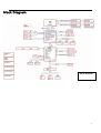
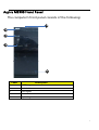
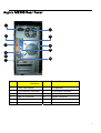
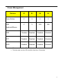
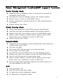
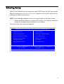
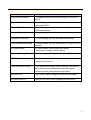
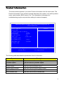
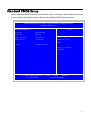
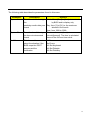
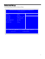
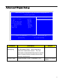
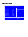
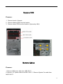
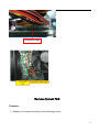
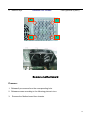
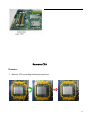
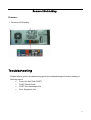
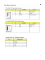
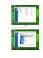
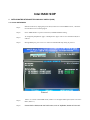
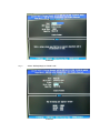
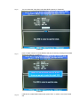
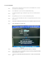
Aspire M3300 Service Guide Service guide files and updates are available on the AIPG/CSD web; for more information please refer to http://csd.acer.com.tw PRINTED IN TAIWAN I Revision History Please refer to the table below for the updates made on Aspire M3300 Service Guide. Date Chapter Updates II Copyright Copyright © 2009 by Acer Incorporated. All rights reserved. No part of this publication may be reproduced, transmitted, transcribed, stored in a retrieval system, or translated into any language or computer language, in any form or by any means, electronic, mechanical, magnetic, optical, chemical, manual or otherwise, without the prior written permission of Acer Incorporated. Disclaimer The information in this guide is subject to change without notice. Acer Incorporated makes no representations or warranties, either expressed or implied, with respect to the contents hereof and specifically disclaims any warranties of merchantability or fitness for any particular purpose. Any Acer Incorporated software described in this manual is sold or licensed "as is". Should the programs prove defective following their purchase, the buyer (and not Acer Incorporated, its distributor, or its dealer) assumes the entire cost of all necessary servicing, repair, and any incidental or consequential damages resulting from any defect in the software. Acer is a registered trademark of Acer Corporation. Intel is a registered trademark of Intel Corporation. Pentium 4 and Celeron are trademarks of Intel Corporation. Other brand and product names are trademarks and/or registered trademarks of their respective holders. III Conventions The following conventions are used in this manual: SCREEN MESSAGES NOTE Denotes actual messages that appear on screen. Gives bits and pieces of additional information related to the current topic. WARNING Alerts you to any damage that might result from doing or not doing specific actions. CAUTION Gives precautionary measures to avoid possible hardware or software problems. IMPORTANT Remind you to do specific actions relevant to the accomplishment of procedures. IV Preface Before using this information and the product it supports, please read the following general information. 1. This Service Guide provides you with all technical information relating to the BASIC CONFIGURATION decided for Acer's "global" product offering. To better fit local market requirements and enhance product competitiveness, your regional office MAY have decided to extend the functionality of a machine (e.g. add-on card, modem, or extra memory capability). These LOCALIZED FEATURES will NOT be covered in this generic service guide. In such cases, please contact your regional offices or the responsible personnel/channel to provide you with further technical details. 2. Please note WHEN ORDERING FRU PARTS, that you should check the most up-to-date information available on your regional web or channel. If, for whatever reason, a part number change is made, it will not be noted in the printed Service Guide. For ACER-AUTHORIZED SERVICE PROVIDERS, your Acer office may have a DIFFERENT part number code to those given in the FRU list of this printed Service Guide. You MUST use the list provided by your regional Acer office to order FRU parts for repair and service of customer machines. V Chapter 1 System Specifications 1 Features……………………………………………………………………………………………... 1 M a i n b o a r d P l a c e m e n t …………………..…………………………….……………………6 B l o c k D i a g r a m …………………..…………………………….……………………7 Aspire M3300 Front Panel………………………………………..…….………..8 Aspire M3300 Rear Panel…………………..…………………………….……………………9 Hardware Specifications and Configurations………………….…….……..10 Power Management Function (ACPI support function)…………………………..…...17 Chapter 2 System Utilities 18 Entering Setup…………………………………………………………………………..19 P r o d u c t I n f o r m a t i o n … … … … … … … … … … … … … … … … … … … … … . . 2 1 Sta n da r d C M O S Fe a t ur es …… … …… …… … …… …… . … ……… … …… …… … …… ……22 Advanced BIOS Features………………………………………..……………………24 Advanced Chipset Setup………………………………………..……………………26 Integrated Peripherals…………………………...…………………………………………..27 P o w e r M a n a g e m e n t … … … … … … … … … … … … … … … … … … … … … … 2 8 PC Health Sta tus……………………………………………………………...30 Fre qu e nc y /Vo l ta ge C on tr ol ……… … …. . …… ……… … ……… … .… … .31 Load Default Settings………………………………………………..……. 32 B I O S S e c u r i t y F e a t u r e s … … … … … . . … … … … … … … … … … . … … . 3 3 S a v e & E x i t S e t u p … … … … … … … … … … … … … … … … … … … . … … … … 3 4 E x i t W i t h o u t S a v i n g … … … … … … … … … … … … … … … … … … … . … … . . 3 5 Chapter 3 Machine Disassembly and Replacement 36 G e n e r a l I n f o r m a t i o n … … … … … … … … … … … … … … … … … … … … … . 3 7 D i s a s s e m b l y P r o c e d u r e … … … … … … … … … … … … … … … … … … … … 3 8 A s p i r e M 3 3 0 0 D i s a s s e m b l y P r o c e d u r e … … … … … . … . . … … 3 9 Chapter 4 Troubleshooting 53 Chapter 5 Jumper and Connector Information54 Jumper Setting…………………………………………………..………………..54 Chapter 6 FRU (Field Replaceable Unit) List 59 E x p l o d e d D i a g r a m … … … … … … … … … … … … … … … … … … … … … … . 5 9 F R U L i s t … … … … … … … … … … … … … … … … … … … … … … … … … 6 0 Chapter 7 Intel Raid I n t e l R a i d … … … … … … … … … … … … … … … … … … … … … … … … … . 6 3 System Specifications Features Operating System Microsoft Windows Vista Home Premium SP1 32/64bit Microsoft Windows Vista Home Basic SP1 32bit FreeDOS Linpus Linux Console mode Linpus Linux X-Windows mode Processor Socket Type: AMD Socket AM3 Processor Type: AM3 CPUs Chipset AMD RS780 + AMD SB710 PCB Form Factor: Micro ATX Dimension/Layer: 244mm x244mm Memory Memory Type: DDR3 800/1066/1333/1600 Support single channel 64 bit mode with maximum memory size up to 8GB Support un-buffered DIMM (RS780) DIMM Slot: 4 Memory Max: 1GB/2GB devices technologies Capacity: 1GB to 8GB Max memory support PCI PCI Express Slot Type: x16 PCI Express x16 Slot Quantity: 1 1 PCI Express Slot Type: x1 PCI Express x1 Slot Quantity: 1 PCI Slot Type: PCI 2.25V slots PCI Slot Quantity: 2 FDD Slot Quantity: 1 Design Criteria: Should support 1.44MB/3 mode 3.5” Devices IDE Slot Type: 40pin PATA IDE slot Slot Quantity: 1 Transfer rate support: ¾ PIO Mode: 0/1/2/3/4 ¾ ATA mode: 33/66/100/133 Storage Type support: ¾ DVD ROM/DVD SuperMultiPlus SATA Slot Type: SATA slot Slot Quantity: 6 Storage Type support: HDD/BD /DVD-ROM/ DVD SuperMultiPlus Audio Audio Type: HD audio codec Audio Channel: 7.1 channel Audio Controller /Codec: Connectors support: ALC888S-VC2 HD codec 7.1 Rear 6 jack follow HD audio definition, example as below Audio jacks color coding: should meet Microsoft Windows Logo Program 2 Device Requirements: Audio-0002 2 S/PDIF-out header (1*4) 1 internal speaker header (2*4) 1 front panel audio header (2*5) Add HD de-pop CKT (the attachment is the reference, please propose your solution) S/N ratio: 90 dB at rear output jack LAN Controller: Marvell 8071 Gigabit Ethernet controller Port : 1 x RJ45 rear port for Gigabit Ethernet Design Criteria: Should be worked under 10/100/1000Mbs environment Reserved disable function on both hardware & BIOS side. Default is enabled Support DASH 1.0/1.1 feature USB Controller Type: SB710 Ports Quantity: 12 4 port for rear ports On-board: 4 2*5 headers ( 6 ports) 4 ports for front daughter board 2 ports for internal card reader Connector Pin: standard Intel FPIO pin definition Data transfer rate support: USB 2.0/1.1 1394 Controller: Jmicron JM831 1394a controller Connector Quantity: 2 1 rear 6pin IEEE1394 port 3 1 2x5pin onboard jumper BIOS BIOS Type: AMI Kernel with Acer skin Size: 4Mb or 8Mb Note: Boot ROM should be included (PXE function should be built in with default and RPL function is optional by service BIOS) BIOS shall auto detect FDD to avoid checksum error when boot I/O Connector Controller: Super I/O ITE 8718 Rear I/O Connector 1 PS/2 Keyboard port, 1 PS/2 Mouse port 1 D-Sub port and HDMI port 4 USB ports 1 RJ45 LAN port 7.1 channel phone jack (6 audio jacks) for ALC888S sku On-board connectors 1 AM3 CPU socket 4 DDR3 memory sockets 1 PCI Express x16 slot 1 PCI Express x 1 slot 2 PCI slots 1 FDD slot 1 PATA IDE connector 6 SATA2 connectors 3 2*5 pin Intel FPIO specification USB pin connectors (follow Intel FPIO standard Specification) 4 1 2*5 pin Intel FPIO spec. Microphone In/ Headphone Out pin connectors 1 1*4 S/PDIF out header (for ALC888S sku) 2 3 pin CPU Fan connector 1 3 pin System FAN connector with linear circuit 1 24pin + 4pin ATX interface PS3/PS2 SPS connector 1 2*7 pin front panel IO header 1 Jumper for clear CMOS 1 on board buzzer 2 reserved 2pin GPIO connector Color management for on board connecter (pls provide proposal) Power Supply Power Supply Mounting Features Chassis accepts ATX-style power supply Chasses accepts PS2, PS3 style power supply Features for internal mounting tab Location of 4 external mounting holes Power Supply Electrical Design Feature 500W/250w in stable mode (Acer Assign System Power Unit) Voltage design should be covered +5V, +3.3V, +12V, +5VSB, -12V (attention to 12V output capability) Demand for both PFC/Non-PFC solutions (two different quotations are needed) Minimum 4 Serial ATA power connector solution should be included (by default) Minimum 1 big 4-pin graphic card connector included Minimum small 4-pin power connector included Non-PFC version should provide switch selector for 115/230V AC input and universal for worldwide PS2 style 5 Block Diagram Block Diagram 6 Aspire M3300 Front Panel The computer’s front panel consists of the following: Label Description 1 ACER Logo 2 Optical drive 3 Card reader 4 Power Button 5 Aspire Logo 7 Aspire M3300 Rear Panel 1 7 2 8 3 9 10 4 5 11 6 Label Label Description Description 1 Power card socket 7 Fan aperture 2 PS/2 keyboard connector 8 PS/2 mouse connector 3 HDMI connector 9 System Fan 4 USB 2.0 connector 10 Monitor connector 5 LAN connector 11 1394 connector 6 Audio connector 12 8 Hardware Specifications and Configurations Processor Item Specification Type Processor Type: AM3 CPUs Socket AMD Socket AM3 Minimum operating speed 0 MHz (If Stop CPU Clock in Sleep State in BIOS Setup is set to Enabled.) BIOS Item Specification BIOS code programmer AMI Kernel with Acer skin BIOS version P03-A0 BIOS ROM type SPI Flash BIOS ROM size 4Mb or 8Mb Support protocol SMBIOS(DMI)2.4/DMI2.0 Device Boot Support - 1st priority: SATA HDD 2nd priority: CD-ROM 3rd priority: Removable Device 4th priority: LAN 5th priority: USB device Support to LS-120 drive YES Support to BIOS boot block feature YES 9 BIOS Hotkey List Hotkey Del Function Enter BIOS Setup Utility Description Press while the system is booting to enter BIOS Setup Utility. Main Board Major Chips Item Specification North Bridge AMD RS780 South Bridge AMD SB710 APG controller AMD RS780 Super I/O controller Super I/O ITE 8718 Audio controller HD audio codec ALC888S-VC2 HD codec 7.1 LAN controller Marvell 8071/ Gigabit Ethernet controller HDD controller AMD SB710 Keyboard controller Super I/O ITE 8718 10 Memory Combinations Slot Memory Total Memory Slot 1 1Gb/2Gb 1GB~2GB Slot 2 1Gb/2Gb 1GB ~2GB Slot 3 1Gb/2Gb 1GB ~2GB Slot 4 1Gb/2Gb 1GB ~2GB Maximum System Memory Supported 1GB ~8GB System Memory Item Specification Memory slot number 4 slot Support Memory size per socket 1Gb/2Gb Support memory type DDR3 Support memory interface DDR3 800/1066/1333/1600 Support memory voltage 1.5V Support memory module package 240-pin DDR3 Support to parity check feature Yes Support to error correction code (ECC) feature No Memory module combinations You can install memory modules in any combination as long as they match the above specifications. 11 Audio Interface Item Specification Audio controller RS780 Audio controller type ALC888S Audio channel codec 7.1 Audio function control Enable/disable by BIOS Setup Mono or stereo Stereo Compatibility Sound Blaster Pro/16 compatible Mixed digital and analog high performance chip Enhanced stereo full duplex operation High performance audio accelerator and AC’97 support Full native DOS games compatibility Virtual FM enhances audio experience through real-time FM-to-Wavetable conversionMPU-401 (UART mode) interface for Wavetable synthesizers and MIDI devices Integrated dual game port Meets AC’97and WHQL specifications Music synthesizer Yes, internal FM synthesizer Sampling rate 48 KHz (max.) MPU-401 UART support Yes Microphone jack Supported Headphone jack Supported 12 SATA Interface Item Specification SATA controller RS780 SATA controller resident bus PCI bus Number of SATA channel SATA X 6 Support bootable CD-ROM YES Floppy disk drive Interface Item Specification Floppy disk drive controller Super I/O ITE 8718 Floppy disk drive controller resident bus ISA bus Support FDD format 360KB, 720KB, 1.2MB, 1.44MB, 2.88MB 13 USB Port Item Specification Universal HCI USB 2.0/1.1 USB Class Support legacy keyboard for legacy mode USB Connectors Quantity 4 ports for rear I/O 4 ports for front daughter board 2 ports for 3.5’’ card reader module Environmental Requirements Item Specification Temperature Operating +5°C ~ +35°C Non-operating -20 ~ +60°C (Storage package) Humidity Operating 15% to 80% RH Non-operating 10% to 90% RH Vibration Operating (unpacked) 5 ~ 500 Hz: 2.20g RMS random, 10 minutes per axis in all 3 axes 5 ~500 Hz: 1.09g RMS random, 1 hour per axis in all 3 axes 14 Power Management Devices S1 S3 S4 S5 Power Button V V V V USB V V N/A N/A PME Disabled Disabled Disabled Disabled RCT Disabled Disabled Disabled Disabled WOR Disabled Disabled Disabled Disabled Keyboard/Mouse Devices wake up from S3 should be less than Devices wake up from S5 should be less than 10 seconds 15 Power Management Function(ACPI support function) Device Standby Mode Independent power management timer for hard disk drive devices(0-15 minutes,time step=1minute). Hard Disk drive goes into Standby mode(for ATA standard interface). Disable V-sync to control the VESA DPMS monitor. Resume method:device activated (keyboard for DOS, keyboard &mouse for Windows. Resume recovery time 3-5sec. Global Standby Mode Global power management timer(2-120minutes,time step=10minute). Hard disk drive goes into Standby mode(for ATA standard interface). Disable H-sync and V-sync signals to control the VESA DPMS monitor. Resume method: Resume to original state by pushing external switch Button,modem ring in,keyboard an mouse for APM mode. Resume recovery time :7-10sec Suspend Mode Independent power management timer(2-120minutes,time step=10minute)or pushing extern switch button. CPU goes into SMM CPU asserts STPCLK# and goes into the Stop Grant State. LED on panel turns amber colour. Hard disk drive goes into SLEEP mode (for ATA standard interface). Disable H-sync and V-sync signals to control the VESA DPMS monitor. Ultra I/O and VGA chip go into power saving mode. Resume method: Resume to original state by pushing external switch Button,modem ring in,keyboard an mouse for APM mode Return to original state by pushing external switch button,modem ring in and USB keyboard for ACPI mode. ACPI ACPI specification 1.0b S0,S1,S2 and S5 sleep state support. On board device power management support. On board device configuration support 16 System Utilities The manufacturer or the dealer already configures most systems. There is no need to run Setup when starting the computer unless you get a Run Setup message. The Setup program loads configuration values into the battery-backed nonvolatile memory called CMOS RAM. This memory area is not part of the system RAM. NOTE: If you repeatedly receive Run Setup messages, the battery may be bad/flat. In this case, the system cannot retain configuration values in CMOS. Before you run Setup, make sure that you have saved all open files. The system reboots immediately after you exit Setup. 17 Entering Setup Power on the computer and the system will start POST (Power On Self Test) process. When the message of “Press DEL to enter SETUP” appears on the screen, press the key of [Delete] to enter the setup menu. NOTE: If the message disappears before you respond and you still wish to enter Setup, restart the system by turning it OFF and On. You may also restart the system by simultaneously pressing [Ctrl+ Alt+ Delete]. The Setup Utility main menu then appears: CMOS Setup Utility-Copyright(C) 1985-2008,American Megatrends, Inc. Product Information PC Health Status Standard CMOS Features Frequency/VoltageControl Advance BIOS Features CMOS Load Default Settings Advanced Chipset Features BIOS Security Features Integrated Peripherals Save and Exit Power Management Setup Exit without saving KLIJ: Move Enter: Select F1: General Help +/-/: Value F10: Save ESC: Exit F9: Optimized Defaults 18 The items in the main menu are explained below: Parameter Description Production Information This page shows the relevant information of the main board Standard CMOS Features This setup page includes all the items in standard compatible BIOS Advance BIOS Features This setup page includes all the items of Award special enhanced features Advance Chipset Features This setup page includes all advanced chipset features Integrated Peripherals This setup page includes all onboard peripherals Power Management Setup This setup page includes all the items of Green function features PC Health Status This setup page is the System auto detect Temperature, voltage, and fan speed Frequency/Voltage Control This setup page is the System Frequency/Voltage setup BIOS Security Features Change, set or disable password. It allows you to limit access to the System Load Optimized Defaults Load Optimized Settings Default Settings indicates the value of the system parameters which the system would be in best performance configuration Save and Exit Save CMOS value settings to CMOS and exit setup Exit without saving Abandon all CMOS value changes and exit setup 19 Product Information The screen below appears if you select Product Information from the main menu: The Product Information menu contains general data about the system, such as the product name, serial number, BIOS version, etc. This information is necessary for troubleshooting (maybe required when asking for technical support). CMOS Setup Utility-Copyright(C) 1985-2008,American Megatrends, Inc. Product Information Processor Information : Processor Type AMD Phenom(tm) II X3 710 Processor Processor Speed 2.6GHZ System memory 1023MB System Manufacturer : Acer Product Name Aspire M3300 System Serial Number : System BIOS Version : P03-A0 BIOS Release Date : 03/28/2009 Asset Tag Number Item Help : KLIJ: Move Enter: Select F1: General Help +/-/: Value F10: Save ESC: Exit F9: Optimized Defaults The following table describes the parameters found in this menu: Parameter Description Processor Type This item lists the Processor Type e Processor Speed This item lists the Processor Speed System memory This item lists the System memory Product Name This item lists the product name System Serial Number This item lists the system serial number System BIOS Version This item lists the system BIOS version BIOS Release Date This item lists the BIOS release date 20 Standard CMOS Setup Select standard CMOS features from the main menu to configure some basic parameters in your system the following screen shows the standard CMOS features menu: CMOS Setup Utility-Copyright(C) 1985-2008,American Megatrends, Inc. Standard CMOS Features Standard CMOS Features Item Help System Date [Wed 04/08/2009] System Time [04:44:56] Primary IDE Master [Not Detected] Primary IDE Slave Use [ENTER], [TAB] or [SHIFT-TAB] to select [Not Detected] A field . Halt on [ALL,But Keyboard] Use [+] or [-] to configure system Time. KLIJ: Move ENTER: Select Item F1: General Help +/-/: Value F10: Save ESC: Exit F9: Optimized Defaults BIOS Security Features 21 The following table describes the parameters found in this menu. Parameter Description Options System Date To set the date following Week: From [Sun.] to [Sat.]. determined the by BIOS and is display only weekday-month-date-year Day: from [1] to [31] (or the maximum format allowed in the month. Year: from 1999 to 2099 System Time To set the time following the hour-minute-second format The items format is [hour] [minute][second]. The time is calculated base on the 24-hour timer clock. Halt On This item enables use to select the situation if the BIOS stops the POST process and the notification All Errors No Errors All, But Keyboard All, But Diskette All, But Disk/Key 22 Advanced Setup The following screen shows the Advanced Setup: CMOS Setup Utility-Copyright(C) 1985-2008,American Megatrends, Inc. Advanced BIOS Features Quick Boot [Enabled] Quiet Boot [Enabled] Item Help 1st Boot Device [Hard Disk] 2nd Boot Device [SATA:HL-DT-ST BDDV] 3rd Boot Device [USB:Generic Compac] 4th Boot Device [Network:B02 D00 Yu] Optical Disk Drive Priority [Press Enter] Removable Drive Priority [Press Enter] Bootup Num-Lock [ON] USB Keep Message [Disabled] KLIJ: Move Enter: Select F1: General Help +/-/: Value F10: Save ESC: Exit F9: Optimized Defaults 23 The following table describes the parameters found in this menu. Parameter Description Options Quick Boot Allows BIOS to skip certain tests while booting. This will decrease the time needed to boot the system [Enabled], [Disabled] 1 st Boot Device The item allows you to see the sequence of boot device where BIOS attempts to load the disk operation system. 2 nd Boot Device 3 rd Boot Device 4 th Boot Device Optical Disk Drive Priority Specifies the boot device. Priority sequence from available Hard Drives Removable Device Priority Boot up Num-Lock On Select Power-on state for Numlock On,Off USB Beep Message Enables the beep during USB device enumeration [Enabled], [Disabled] 24 Advanced Chipset Setup CMOS Setup Utility-Copyright(C) 1985-2008,American Megatrends, Inc. Advanced Chipset Features Item Help Advanced Chipset Features AMD Cool `n'Quiet AMD-V Memory Hole Remapping UMA Frmae Buffer Size Current UMA Size Surround View Primary video KLIJ: Move Enter: Select F1: General Help Parameter [Enabled] [Enabled] [Enabled] [Auto] [128MB] [Disabled] [Auto] +/-/: Value F10: Save ESC: Exit F9: Load Default Settings Description Options Memory Hole Remapping You can reserve this area of system memory for ISA adapter ROM. When this area is reserved, it cannot be cached. The user information of peripherals that need to use this area of system memory usually discuss their memory requirements. Disabled/Enabled Primary Video Priority for Auto : PCIE -> Onboard -> PCI Auto/PCIE/Onboa rd/PCI 25 Integrated Peripherals CMOS Setup Utility – Copyright (c) 1985-2008, American Megatrends, Inc. Integrated Peripherals Item Help Integrated Peripherals Onboard IDE Controller Onboard SATA Controller Onboard SATA Mode Onboard USB Controller Legacy USB Support USB Storage Emulation USB Storage Emulation USB Storage Emulation USB Storage Emulation USB Storage Emulation Onboard Graphics Mode Onboard Audio Controller Onboard LAN Controller Onboard LAN Option ROM Onboard 1394 Controller Onboard Floppy Controller KLIJ: Move Enabled] Enabled] [AHCI] [Enabled] [Enabled] [Auto] [Auto] [Auto] [Auto] [Auto] [UMA] [Enabled] [Enabled] [Disabled] [Enabled] [Enabled] Enter: Select F1: General Help Options [Disabled] [Enabled] +/-/: Value F10: Save ESC: Exit F9: Optimized Defaults 26 The following table describes the parameters found in this menu. Parameter Description Options Onboard IDE Controller This item is only available when onboard IDE controller is Enabled Disabled/Enabled Onboard SATA Controller This item is only available when onboard SATA controller is Enabled Disabled/Enabled Onboard SATA Mode This item is only available when onboard ESATA controller is AHCI Mode. Disabled/AHCI Mode Onboard USB Controller Always enabled USB keyboard during POST no matter what option is set Disabled/Enabled Legacy USB Support This item is only available when on board USB controller is enabled Disabled/Enabled Onboard Audio Controller Always enabled Audio POST no matter what option is set Disabled/Enabled Onboard LAN Controller Always enabled Audio POST no matter what option is set Disabled/Enabled Onboard LAN Option ROM This item is only available when onboard LAN controller is enabled Disabled/Enabled Onboard 1394 Controller Always enabled Audio POST no matter what option is set Disabled/Enabled Onboard Floppy Controller Always enabled Audio POST no matter what option is set Disabled/Enabled 27 Power Management The Power Management menu lets you configure your system to most effectively save energy while operating in a manner consistent with your own style of computer use. The following screen shows the Power Management parameters and their default settings: CMOS Setup Utility– Copyright (c) 1985-2008,American Megatrends, Inc Power Management Setup ACPI Aware O/S ACPI Suspend Mode Power On by RTC Alarm Power On by PCIE Devices Power On by PCI Devices Wake Up by PS/2 KB/Mouse Wake Up by USB KB//Mouse Restore On AC Power Loss [Yes] [S3 (STR)] [Disabled] [Disabled] [Disabled] [Enabled] [Enabled] [Last State] Item Help Yes/ No ACPI support for Operating System. Yes: If OS supports ACPI. No: If OS does not support ACPI. KLIJ: Move Enter: Select F1: General Help +/-/: Value F10: Save ESC: Exit F9: Optimized Defaults The following table describes the parameters found in this menu. Parameter ACPI Aware O/S ACPI Suspend Mode Description Control wake up event for S1/S3/S4/S5 Options No/Yes S1(POS)/S3 (STR) Power On by RTC Alarm Disabled/Enabled Power On by PCIE Devices Disabled/Enabled Power On by PCI Devices Disabled/Enabled Wake Up by PS/2 KB/Mouse Wake Up by USB KB//Mouse Control wake up event for S1/S3 Disabled/Enabled Disabled/Enabled 28 PC Health Status CMOS Setup Utility– Copyright (c) 1985-2008,American Megatrends, Inc. PC Health Status CPU Temperature System Temperature CPU Fan Speed System Fan Speed CPU Core +1.1V +3.30V +5.00V +12.0V 5VSB : 18℃/64℉ : 25℃/77℉ : 1662 RPM : N/A : 1.328V : 1.104V : 3.360V : 4.999V : 12.096V : 4.999V VBAT : [Disabled] CPU Shutdown Temperature [Disabled] Smart Fan [Enabled] F1: General Help Fan configuration mode setting 3184V System Shutdown Temperature KLIJ: Move Enter: Select Item Help +/-/: Value F10: Save ESC: Exit F9: Optimized Defaults The following table describes the parameters found in this menu: Parameter Description Options CPU/System Temperature Detect CPU Temperature automatically CPU/SYSTEM FAN Speed (RPM) Detect CPU/SYSTEM Fan Speed Status automatically System Shutdown Temperature The item displays the system Shutdown Temperature Enabled/Disabled CPU Shutdown Temperature The item displays the CPU Shutdown Temperature Enabled/Disabled Smart FAN The item displays the system Smart Fan Function status. It is always enabled by system. Enabled/Disabled 29 Frequency/Voltage Control CMOS Setup Utility-Copyright(C) 1985-2008,American Megatrends, Inc. Frequency Control Item Help Frequency/Voltage Control CPU Spread Spectrum ATIG Spread Spectrum SRC Spread Spectrum KLIJ: Move Enter: Select F1: General Help Parameter [Enabled] [Enabled] [Disabled] +/-/: Value F10: Save ESC: Exit F9: Optimized Defaults Description Options CPU Spread Spectrum Always auto detect Spread Spectrum Disabled/Enabled ATIG Spread Spectrum Always auto detect Spread Spectrum Disabled/Enabled SRC Spread Spectrum Always auto detect Spread Spectrum Disabled/Enabled 30 BIOS Security Features CMOS Setup Utility BIOS Security Features Supervisor Password User Password Change Supervisor Password : Not installed : Not Installed [Press Enter] KLIJ: Move Enter: Select F1: General Help Item Help Install or Change the Password +/-/: Value F10: Save ESC: Exit F9: Optimized Defaults The following table describes the parameters found in this menu: Parameter Change Supervisor Password Description Options This item is only available when Press Enter supervisor password is installed, If clear supervisor password, user password should also be cleared. All setup items will be view-only except user password item when login with user password 31 Load Default Settings This option opens a dialog box that lets you install defaults for all appropriate items in the Setup Utility. CMOS Setup Utility Product Information PC Health Status Standard CMOS Features Frequency/ Control Advance BIOS Features CMOS Load Default Settings? Advanced Chipset Features BIOS Integrated Peripherals [OK] Power Management Setup KLIJ: Move Enter: Select F1: General Help Loab Default Settings IOS LoabSecurity DefaultFeatures Settings Save & Exit Setup [Cancal] Exit Without Saving +/-/: Value F10: Save ESC: Exit F9: Optimized Defaults The following table describes the parameters found in this menu: Parameter Description Load Default Settings Select the field loads the factory defaults for BIOS and Chipset Features, which the system automatically detects. This option opens a dialog box that lets you install optimized defaults for all appropriate items in the Setup Utility. Options 32 Save & Exit Setup Highlight this item and press <Enter> to save the changes that you have made in the Setup Utility and exit the Setup Utility. CMOS Setup Utility Product Information PC Health Status Standard CMOS Features Frequency/Voltage Control Advance BIOS Features CMOS BIOS Security Features Save and exit? Advanced Chipset Features Loab Default Settings Integrated Peripherals Power Management Setup Save & Exit Setup Save & Exit Setup [OK] KLIJ: Move Enter: Select F1: General Help [Cancal] Exit Without Saving +/-/: Value F10: Save ESC: Exit F9: Load Default Settings The following table describes the parameters found in this menu: Parameter Description Save and exit Press <Enter> to save the changes that have made in the Setup Utility and exit the Setup Utility. Press<Y> to save and Exit or <N> to return to the main menu. Options 33 Exit Without Saving Highlight this item and press <Enter> to discard any changes that you have made in the Setup Utility and exit the Setup Utility. CMOS Setup Utility Product Information PC Health Status Standard CMOS Features Frequency/Voltage Control Advance BIOS Features CMOS BIOS Security Features Discard changes and exit setup? Loab Default Settings Advanced Chipset Features Integrated Peripherals [OK] Power Management Setup KLIJ: Move Enter: Select F1: General Help Parameter Save & Exit Setup [Cancal] Exit ExitWithout WithoutSaving Saving +/-/: Value F10: Save ESC: Exit F9: Load Default Settings Description Options Discard changes and Press<Enter> to discard any changes and exit setup exit the Setup Utility 34 Machine Disassembly and Replacement To disassemble the computer, you need the following tools: Wrist grounding strap and conductive mat for preventing electrostatic discharge. Wire cutter Phillips screwdriver (may require different size). NOTE: The screws for the different components vary in size. During the disassembly process, group the screws with the corresponding components to avoid mismatches when putting back the components. 35 General Information Before You Begin Before proceeding with the disassembly procedure, make sure that you do the following: 1. Turn off the power to the system and all peripherals. 2. Unplug the AC adapter and all power and signal cables from the system 36 Disassembly Procedure This section tells you how to disassemble the system when you need to perform system service. Please also refer to the disassembly video, if available. CAUTION: Before you proceed, make sure you have turned off the system and all peripherals connected to it. 37 aBengal II Aspire M3300 Standard Disassembly Process Bezel Process: 1. According to the requirement, paste ATI, OS, CPU, HDMI and marketing label by SKU. 38 Remove side cover Process: 1. Put the Computer on the worktable lightly. 2. Release left/right side cover with 4 screws then remove left/right side cover. 39 Remove CPU fan pipe Process: 1. Release the CPU fan pipe. 2 3 1 4 Remove Cards Process: 1. Release the slot cover tooless 2. Remove VGA 、TV、Modem Card,the following list is for your reference about the mutual location relation (Optional by SKU). 40 41 Remove HDD Data Cables Process: 1. Remove master HDD data cable from M/B SATA1/SATA3(Optional by SKU). 2. Remove slave ODD data cable from M/B SATA2/SATA4(Optional by SKU) Remove slave HDD cable Remove master HDD cable 42 Remove ODD DATA cable Process: 1. Remove master ODD data/power cable from Master ODD. Remove HDD power cable Process: 1. Remove master HDD data cable from master HDD. 2. Remove slave HDD data cable from slave HDD. 43 Remove Cables Process: 1. 2. 3. 4. 5. Remove Power SW cable cable from M/B. Remove FI/O USB cable from M/B. Remove MCR USB cable from M/B. Remove Card reader cable from M/B. Remove audio cable from the “AUDIO” port on M/B. 44 Remove HDD Process: 1. Remove the screws and take out HDD bracket . 2. Remove two sides with 2 screws for each and then remove the master HDD and Slave HDD. 3. Remove Slave HDD from the second HDD location. (Optional by SKU) Master HDD location 2 Slave HDD location 4 1 3 Remove card reader Process: 1. Remove card reader from chassis. 45 Remove ODD Process: 1. Remove bezel of chassis. 2. Remove Master ODD from the location. 3. Remove slave ODD from the location. (Optional by SKU) Remove Cables Process: 1. Remove M/B power cable from M/B “ATX1”. 2. Remove 12 V power cable from M/B” JPW1” 3. Remove System Fan cable from M/B”SYS-F2”. 46 M/B power cable Remove System FAN Process: 1. Release four screws according to the following picture. 47 2. Release four screws. Remove Sys FAN (Optional by SKU) 4 1 2 3 Remove mother board Process: 1. Release 8 pcs screws form the corresponding hole. 2. Release screws according to the following picture in turn. 3. Remove the Mother board from chassis. 48 Remove CPU cooler Process: 1. Remove cooler power cable from M/B “CPU-F”. 2. Open the handle.and clip.Remove Cooler from the Retention module. Remove memory Process: 1. Remove the first Memory from DIMM. 2. Remove the second Memory from DIMM2 (Optional by SKU). 49 Remove CPU Process: 1. Remove CPU according following the pictures. 50 Remove I/O shielding Process: 1. Remove I/O Shielding. Troubleshooting Please refer to generic troubleshooting guide for troubleshooting information relating to following topics: Power-On Self-Test (POST) POST Check Points POST Error Messages List Error Symptoms List 51 52 53 ATX_POWER: ATX 24-pin Power Connector 1 2 3 4 5 6 7 8 9 10 11 12 13 14 15 16 17 18 19 20 21 22 23 24 Pin Signal Name Pin Signal Name 1 +3.3 13 +3.3V 2 +3.3 14 -12V 3 COM 15 COM 4 +5V 16 PS_ON 5 COM 17 COM 6 +5V 18 COM 7 COM 19 COM 8 PWR OK 20 -5V 9 5VSB 21 +5V 10 +12V 22 +5V 11 +12V 23 +5V 12 +3.3V 24 COM 54 55 56 FRU (Field Replaceable Unit) List This chapter gives you the FRU (Field Replaceable Unit) listing in global configurations of Aspire M3300 Refer to this chapter whenever ordering for parts to repair or for RMA (Return Merchandise Authorization). NOTE: Please note WHEN ORDERING FRU PARTS, that you should check the most up-to-date information available on your regional web or channel. For whatever reasons a part number change is made, it will not be noted in the printed Service Guide. For ACER-AUTHORIZED SERVICE PROVIDERS, your Acer office may have a DIFFERENT part number code to those given in the FRU list of this printed Service Guide. You MUST use the local FRU list provided by your regional Acer office to order FRU parts for repair and service of customer machines. 57 Exploded Diagram 58 Aspire M3300 FRU List Category Description Part Number MAINBOARD Mainboard FRS780F ATI RS780 SB710 Marvell 8071 ATX w/o IO Bracket MB.SBT09.001 w/i 1394 LF onboard DVI D-Sub CPU Cooler Fan Cooler K8_M2 AVC Z7UB008 AVC fan7015 HI.12900.001 AMD Phenom II 925 KC.PH202.925 AMD Phenom II 805 KC.PH202.805 AMD Phenom II 720 KC.PH202.720 1GB, DDRIII1066(Samsung) KN.1GB0B.022 2GB, DDRIII1333(Samsung) KN.2GB0B.008 CPU Memory HDD 160G SATA2 8MB 7200 NCQ(HGST) KH.16007.023 320G SATA2 8MB 7200 NCQ(WD) KH.32008.016 320G SATA2 8MB 7200 NCQ(Seagate) KH.32001.009 640G SATA2 16MB 7200 NCQ(Seagate) KH.64001.001 DVD-ROM DDVD16XS SATA KV.0160F.001 ODD 60 DVD Super Multi DSM16XS SATA LabelFlash KU.0160D.045 BD COMBO HH DL 4X LF Black Bezel SATA KO.0060D.001 BD RW HH DL 4X LF Black Bezel SATA KU.0060D.001 TV-Tuner PE988-A TV Tuner Card PCIe Hybrid ATSC with S/W Encoder TU.10500.038 IOI 16-in-1 CR M1/M3 w/3.5", USB2.0, UsBSET UT330-LK CR.10400.071 Card Reader Modem HPI56L6, Modem PCI card, LSI Universal Modem (PCI) 56K V.92 - Pinball (P40) FX.10100.006 Power Supply PS-6301-08A2-ROHS, Non-PFC 300W (Modulized) PY.3000B.013 FSP450-60EP, FR 500W 82+ (Eneergy Star5.0) PY.50008.003 Logitech 0810_USB Optical mouse USB M-UAY-ACR2 MS.11200.014 Mouse KEYBOARD 61 Keyboard LITE-ON SK-9625 USB Standard 104KS Black US with new KB.USB0B.082 color AC-MT-018 62 Intel RAID SOP (Windows) 2.Intel(R) Matrix Storage Console 2-1:Create a“RAID Ready” System into" RAID 0" with two Hard Drives by‘Create RAID Volume from Existing HDD Drive ’. Step 1: Install Vista OS with one SATA HDD. Step 2: Shut down the system,then add one Serial ATA hard drive in the system. Step 3: Boot to OS desktop, open the Intel® Matrix Storage Console. Picture1 Picture1 Step 4: Click on the by‘Create RAID Volume from Existing HDD Drive ’ to create a RAID volume. Picture2 Step 5: Click "Next" at create a RAID volume window. Picture3 Step 6: Key the name in "Volume Name" and select "RAID 0" in RAID Level. Picture4 Step 7: Select minimum HDD as "Source Hard Drive". Picture5 Picture6 Step 8: Select Menber Hard Drive(s). Picture7 Step 9: Specify Volume Size then press "next". Picture8 Step 10: Press "next" to finish setup and start create RAID0. Picture9 Step 11: It may takes half and hours to create RAID0.After create completely,it will ask to reboot to finish create RAID0. 2-2:Create a“RAID Ready” System into" RAID 1" with two Hard Drives by‘Create RAID Volume from Existing HDD Drive ’. Install Vista OS with one SATA HDD. Step 1: Step 2: Shut down the system,then add another Serial ATA hard drive in the system. Step 3: Boot to OS desktop, open the Intel® Matrix Storage Console. Step 4: Click on the by‘Create RAID Volume from Existing HDD Drive ’ to create a RAID volume. Step 5: Click "Next" at create a RAID volume window. Step 6: Key the name in "Volume Name" and select "RAID 1" in RAID Level. Picture10 Step 7: Select minimum HDD as "Source Hard Drive". Step 8: Select Menber Hard Drive(s). Step 9: Specify Volume Size then press "next". Step 10: Press "next" to finish setup and start create RAID1. Step 11: It may takes half and hours to create RAID1.After create completely,it will ask to reboot to finish create RAID1. 2-3:Create a“RAID Ready” System into" RAID 5" with three Hard Drives by‘Create RAID Volume from Existing HDD Drive ’. Install Vista OS with one SATA HDD. Step 1: Shut down the system,then add other two serial ATA hard drives in the system. Step 2: Boot to OS desktop, open the Intel® Matrix Storage Console. Step 3: Click on the by‘Create RAID Volume from Existing HDD Drive ’ to create a RAID Step 4: Click "Next" at create a RAID volume window. Step 5: Key the name in "Volume Name" and select "RAID 5" in RAID Level. Step 6: Picture11 Step 7: Select minimum HDD as "Source Hard Drive". Picture12 Step 8: At least select two HDD as Menber Hard Drive(s). Picture13 Step 9: Specify Volume Size then press "next". Step 10: Press "next" to finish setup and start create RAID5. Step 11: It may takes half and hours to create RAID5.After create completely,it will ask to reboot to finish create RAID5. 2-4:Create a“RAID Ready” System into" RAID 10" with three Hard Drives by‘Create RAID Volume from Existing HDD Drive ’. Install Vista OS with one SATA HDD. Step 1: Step 2: Shut down the system,then add other two serial ATA hard drives in the system. Step 3: Boot to OS desktop, open the Intel® Matrix Storage Console. Step 4: Click on the by‘Create RAID Volume from Existing HDD Drive ’ to create a RAID Step 5: Click "Next" at create a RAID volume window. Step 6: Key the name in "Volume Name" and select "RAID 10" in RAID Level. Picture14 Step 7: Select two HDDs as "Source Hard Drive". Picture15 Step 8: At least select two HDD as Menber Hard Drive(s). Step 9: Specify Volume Size then press "next". Step 10: Press "next" to finish setup and start create RAID 10. Step 11: It may takes half and hours to create RAID 10.After create completely,it will ask to reboot to finish create RAID10. 2-5:Create a“RAID Ready” System into" RAID 0" with two Hard Drives by ‘Create RAID Volume ’. Step 1: Step 2: Step 3: Step 4: Install Vista OS with one SATA HDD. Shut down the system,then add another two serial ATA hard drives in the system. Boot to OS desktop, open the Intel® Matrix Storage Console. Click on the by‘Create RAID Volume’ to create a RAID volume. Step 5: Click "Next" at create a RAID volume window. Step 6: Key the name in "Volume Name" and select "RAID 0" in RAID Level. Step 7: At least select two HDDs as "Volume Location". Picture16 Picture17 Step 8: Specify Volume Size then press "next". Picture18 Step 9: Press "next" to finish setup and start create RAID 0. Step 10: It may takes half and hours to create RAID 0.After create completely,it will ask to reboot to finish create RAID 0. Intel RAID SOP 1. INTEL® MATRIX STORAGE TECHNOLOGY CHECK (DOS) 1-1: Create SATA RAID 0 Step 1: Shut down the EUT, unplug the power cable,connect two SATA HDDS to EUT , check the EUT all devices are connect/plug ok Step 2: Press "PWR-BTTN" to power on the EUT,Load BIOS default setting . Step 3: At "Integrated_Peripherals" page "OnChip SATA Type" item set is as "RAID" mode,save and exit. Step 4: During BIOS post, press <Ctrl-I> to enter into Intel RAID setup utility,as picture1. Picture1 Step 5: Select "1" to enter create RAID mode ,if there is no enough avalable space (there was exist a Raid , delete it ). Step 6: Create RAID 0 Mode,enter the RAID name,such as "MyRaid0",default is"Volume0". Picture2 Step 7: Select "RAID0(Stripe)" at "RAID Level". Picture3 Step 8: You can select the "Strip Size" and define RAID capacity in "Capactity". Picture4 Step 9: Press "Create Volume" to create RAID0,it will pop the warning message that all data will be lost,"press "Y" to confirm it. Picture5 Step 10: It will back to create RAID interface,then press "ESC" or select 4 to exit and install OS. 1-2: Create SATA RAID 1 Step 1: Shut down the EUT, unplug the power cable,connect two SATA HDDS to EUT , check the EUT all devices are connect/plug ok Step 2: Press "PWR-BTTN" to power on the EUT,Load BIOS default setting . Step 3: At "Integrated_Peripherals" page "OnChip SATA Type" item set is as "RAID" mode,save and exit. Step 4: During BIOS post, press <Ctrl-I> to enter into Intel RAID setup utility. Step 5: Select "1" to enter create RAID mode ,if there is no enough avalable space (there was exist a Raid , delete it ). Step 6: Create RAID 1 Mode,enter the RAID name,such as "MyRaid1",default is"Volume0". Step 7: Select "RAID1(Mirror)" at "RAID Level". Picture6 Step 8: You can select the "Strip Size" and define RAID capacity in "Capactity". Step 9: Press "Create Volume" to create RAID1,it will pop the warning message that all data will be lost,"press "Y" to confirm it. Step 10: It will back to create RAID interface,then press "ESC" or select 4 to exit and install OS. 1-3: Create SATA RAID 5 Step 1: Shut down the EUT, unplug the power cable,connect three SATA HDDS to EUT , check the EUT all devices are connect/plug ok Step 2: Press "PWR-BTTN" to power on the EUT,Load BIOS default setting . Step 3: At "Integrated_Peripherals" page "OnChip SATA Type" item set is as "RAID" mode,save and exit. Step 4: During BIOS post, press <Ctrl-I> to enter into Intel RAID setup utility. Step 5: Select "1" to enter create RAID mode ,if there is no enough avalable space (there was exist a Raid , delete it ). Step 6: Create RAID 5 Mode,enter the RAID name,such as "MyRaid5",default is"Volume0". Step 7: Select "RAID5(Parity)" at "RAID Level". Picture7 Step 8: You can select the "Strip Size" and define RAID capacity in "Capactity". Step 9: Press "Create Volume" to create RAID5,it will pop the warning message that all data will be lost,"press "Y" to confirm it. Step 10: It will back to create RAID interface,then press "ESC" or select 4 to exit and install OS. 1-4: Create SATA RAID 0+1 Step 1: Shut down the EUT, unplug the power cable,connect four SATA HDDS to EUT , check the EUT all devices are connect/plug ok Step 2: Press "PWR-BTTN" to power on the EUT,Load BIOS default setting . Step 3: At "Integrated_Peripherals" page "OnChip SATA Type" item set is as "RAID" mode,save and exit. Step 4: During BIOS post, press <Ctrl-I> to enter into Intel RAID setup utility. Step 5: Select "1" to enter create RAID mode ,if there is no enough avalable space (there was exist a Raid , delete it ). Step 6: Create RAID 0+1 Mode,firstly create RAID 0 Mode,enter the RAID name,such as "MyRaid0+1",default is"Volume0". Step 7: Select "RAID0(Stripe)" at "RAID Level". Step 8: Select two HDDs in "Disk" by space key. Step 9: Press "Enter" to finish HDD selection and it will back to RAID creation interface. Step 10: Repeat RAID1 creation step and exit,then install OS. Picture8 2-6:Create a“RAID Ready” System into" RAID 1" with two Hard Drives by ‘Create RAID Volume ’. Step 1: Install Vista OS with one SATA HDD. Step 2: Shut down the system,then add another two serial ATA hard drives in the system. Step 3: Boot to OS desktop, open the Intel® Matrix Storage Console. Step 4: Click on the by‘Create RAID Volume’ to create a RAID volume. Step 5: Click "Next" at create a RAID volume window. Step 6: Key the name in "Volume Name" and select "RAID 1" in RAID Level. Step 7: At least select two HDDs as "Volume Location". Step 8: Specify Volume Size then press "next". Step 9: Press "next" to finish setup and start create RAID 1. It may takes half and hours to create RAID 1.After create completely,it will ask to reboot to finish create RAID 1. Step 10: 2-7:Create a“RAID Ready” System into" RAID 5" with two Hard Drives by ‘Create RAID Volume ’. Step 1: Install Vista OS with one SATA HDD. Step 2: Shut down the system,then add another three serial ATA hard drives in the system. Step 3: Boot to OS desktop, open the Intel® Matrix Storage Console. Step 4: Click on the by‘Create RAID Volume’ to create a RAID volume. Step 5: Click "Next" at create a RAID volume window. Step 6: Key the name in "Volume Name" and select "RAID 5" in RAID Level. Step 7: At least select three HDDs as "Volume Location". Step 8: Specify Volume Size then press "next". Step 9: Press "next" to finish setup and start create RAID 5. Step 10: It may takes half and hours to create RAID 5.After create completely,it will ask to reboot to finish create RAID 5. 2-8:Create a“RAID Ready” System into" RAID 10" with two Hard Drives by ‘Create RAID Volume ’. Step 1: Install Vista OS with one SATA HDD. Step 2: Shut down the system,then add another four serial ATA hard drives in the system. Step 3: Boot to OS desktop, open the Intel® Matrix Storage Console. Step 4: Click on the by‘Create RAID Volume’ to create a RAID volume. Step 5: Click "Next" at create a RAID volume window. Step 6: Key the name in "Volume Name" and select "RAID 10" in RAID Level. Step 7: At least select three HDDs as "Volume Location". Step 8: Specify Volume Size then press "next". Step 9: Press "next" to finish setup and start create RAID 10. It may takes half and hours to create RAID 10.After create completely,it will ask to reboot to finish create RAID 10. Step 10: