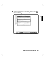
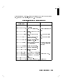
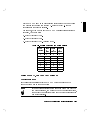
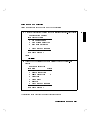
1
HP Apollo 9000 Model 425s and 425t
Owner's Guide
for HP-UX Users
HP Apollo 9000 Series 400 Computers
ABCDE
HP Part No. A2100-90600
Printed in USA August 1991
Edition 1
E0791
Notices
Information in this document is subject to change without notice.
Hewlett-Packard makes no warranty of any kind about this manual, including,
but not limited to, the implied warranties of merchantability and tness for a
particular purpose. Hewlett-Packard shall not be liable for errors contained
herein or direct, indirect, special, incidental or consequential damages about
the furnishing, performance, or use of this material.
Warranty. Please read the enclosed Hewlett-Packard Software Product License
Agreement and Limited Warranty before operating this product. Rights in the
software are oered only on the condition that the customer accepts all terms
and conditions of the License Agreement.
Operating the product indicates your acceptance of these terms and conditions.
If you do not agree to the License Agreement, you may return the unused
product for a full refund.
A copy of the specic warranty terms applicable to your Hewlett-Packard
product and replacement parts can be obtained from your local Sales and
Service Oce.
c 1991 Hewlett-Packard Company
Copyright This document contains information which has been protected by copyright.
All rights are reserved. Reproduction, adaptation, or translation without prior
written permission is prohibited, except as allowed under the copyright laws.
c AT&T, Inc. 1980, 1984, 1986
Copyright c The Regents of the University of California 1979, 1980, 1983,
Copyright 1985.
This software and documentation is based inpart on the Fourth Berkely
Software Distribution under license from the Regents of the University of
California.
Restricted Rights Legend
Use, duplication or disclosure by the United States Government is subject to
restrictions as set forth in subparagraph (c) (1) (ii) of the Rights in Technical
Data and Computer Software clause at FARs 52.227.7013.
Hewlett-Packard Company
Operating Systems Software Division
3404 East Harmony Road
Fort Collins, Colorado 80525
Printing History
This manual's printing date and part number show its current edition. The
printing date will change when a new edition is printed. Minor changes may be
made at reprint without changing the printing date. The manual part number
will change when extensive changes occur.
Manual updates may be issued between editions to correct errors or document
product changes. To ensure that you receive these updates or new editions,
you should subscribe to the appropriate product support service. See your
Hewlett-Packard Sales Representative for details.
August, 1991 Edition 1
This edition applies to HP 9000, Series 425s/t computers only.
Safety Symbols and Conventions
The following conventions are used throughout this manual:
Note
Notes contain important information set o from the text.
Caution
Caution messages indicate procedures which, if not observed,
could result in loss of data or damage to equipment. Do not
proceed beyond a CAUTION sign until the indicated conditions
are fully understood and met.
Warning
Warning messages indicate procedures or practices which, if
not observed, could result in personal injury. Do not proceed
beyond a WARNING sign until the indicated conditions are fully
understood and met.
iv
FCC Statement (For U.S.A. Only)
The Federal Communications Commission (in Subpart J of Part 15, Docket
20780) has specied that the following notice be brought to the attention of the
users of this product.
Warning. This equipment generates, uses, and can radiate radio frequency
energy and if not installed and used in accordance with the instructions
manual, may cause interference to radio communications. It has been
tested and found to comply with the limits for a Class A computing device
pursuant to Subpart J of Part 15 of FCC rules, which are designed to provide
reasonable protection against such interference when operated in a commercial
environment. Operation of this equipment in a residential area is likely to
cause interference in which case the user at his own expense will be required to
take whatever measures may be required to correct the interference.
Manufacturers Declaration (Germany Only)
Herstellerbescheinigung

Hiermit wird bescheinigt, da dieses Gerat in Ubereinstimmung
mit den
Bestimmungen der Postverfugung 1046/84 funkentstort ist. Der Deutschen
Bundespost wurde das Inverkehrbringen dieses Gerates angezeigt und die

Berechtigung zur Uberpr
ufung der Serie auf Einhaltung der Bestimmungen
eingeraumt.
v
VCCI Statement (Japan Only)
Laser Safety Statement (For U.S.A. Only)
(For computers with a CD ROM disk drive installed.)
The CD ROM drive is certied as a Class 1 laser product under the U.S.
Department of Health and Human Services (DHHS) Radiation Performance
Standard according to the Radiation Control for Health and Safety Act of 1968.
This means that the device does not produce hazardous laser radiation. Since
laser light emitted inside the device is completely conned within protective
housings and external covers, the laser beam cannot escape from the machine
during any phase of user operation.
vi
Warning
Use of controls, adjustments, or performing procedures
different from those specified in this manual may result in
hazardous invisible laser radiation exposure. None of the
mechanisms within the mass storage system contain customer
or field-replaceable parts.
The CD ROM drive becomes a Class 3B laser mechanism
when disassembled. If the CD ROM drive is disassembled,
exposure to the invisible laser beam and hazardous invisible
laser radiation could result in blindness. Do NOT disassemble
the CD ROM drive for any reason.
vii
Laser Safety Statement (For Finland Only)
Turvallisuusyhteenveto
Laserturvallisuus
Luokan 1 Laserlaite
Klass 1 Laser Apparat
HP 9000 Model 425 tietokoneeseen voidaan asentaa muistilaitteeksi
laitteensisainen CD-ROM-levyasema, joka on laserlaite. Talloin myos
paalaitteena toimiva tietokone katsotaan laserlaitteeksi.
Kyseinen CD-ROM-livyasema on kayttajan kannalta turvallinen luokan 1
laserlaite. Normaalissa kaytossa levyaseman suojakotelo estaa lasersateen
paasyn laitteen ulkopuolelle.
HP 9000 Model 425 tietokoneen on tyyppihyvaksynyt Suomessa
laserturvallisuuden osalta Tyosuojeluhallitus, Tyosuojeluhallituksen
hyvaksyntanumero TSH 222/6019/90. Laitteiden turvallisuusluokka on
maaritetty valtioneuvoston paatoksen N:o 472/1985 ja standardin SFS-IEC
825 mukaisesti. Tiedot CD-ROM-levyasemassa kaytettavan laserdiodin
sateilyominaisuuksista:
Aallonpituus 780 nm
Teho 0,4 mW
Luokan 1 laser
viii
Contents
1. Product Description
Your HP Apollo 9000 Model 425s and 425t Computer
Model 425t . . . . . . . . . . . . . . . . . .
Model 425s . . . . . . . . . . . . . . . . . .
Features . . . . . . . . . . . . . . . . . . .
Memory . . . . . . . . . . . . . . . . . . .
Graphics . . . . . . . . . . . . . . . . . . .
425s/t Built-In Interfaces . . . . . . . . . . .
SCSI Interface . . . . . . . . . . . . . . .
RS-323 Serial Interface . . . . . . . . . . .
HP Parallel Interface . . . . . . . . . . . .
HP-HIL Interface . . . . . . . . . . . . . .
LAN Interfaces . . . . . . . . . . . . . . .
Internal Mass Storage Devices . . . . . . . . .
Operating Systems . . . . . . . . . . . . . .
.
.
.
.
.
.
.
.
.
.
.
.
.
.
.
.
.
.
.
.
.
.
.
.
.
.
.
.
.
.
.
.
.
.
.
.
.
.
.
.
.
.
.
.
.
.
.
.
.
.
.
.
.
.
.
.
.
.
.
.
.
.
.
.
.
.
.
.
.
.
1-1
1-2
1-2
1-2
1-4
1-5
1-5
1-8
1-8
1-8
1-8
1-9
1-9
1-10
2. Using Your Manuals
Chapter Contents . . . . . . . . .
Finding Documents for Specic Tasks
Installation . . . . . . . . . . .
Conguration . . . . . . . . .
Operation . . . . . . . . . . .
Solving Problems . . . . . . . .
.
.
.
.
.
.
.
.
.
.
.
.
.
.
.
.
.
.
.
.
.
.
.
.
.
.
.
.
.
.
2-1
2-2
2-2
2-3
2-4
2-4
.
.
.
.
.
.
.
.
.
.
.
.
.
.
.
.
.
.
.
.
.
.
.
.
.
.
.
.
.
.
.
.
.
.
.
.
.
.
.
.
.
.
Contents-1
3. Starting Your System for the First Time
Chapter Contents . . . . . . . . . .
Using Instant Ignition . . . . . . . .
Logging In with HP VUE . . . . . .
VUE Functions on the Control Panel
Logging Out . . . . . . . . . . . .
Creating a New User Account . . . .
Setting a New Password . . . . . . .
Shutting Down with VUE . . . . . .
.
.
.
.
.
.
.
.
.
.
.
.
.
.
.
.
.
.
.
.
.
.
.
.
.
.
.
.
.
.
.
.
.
.
.
.
.
.
.
.
.
.
.
.
.
.
.
.
.
.
.
.
.
.
.
.
.
.
.
.
.
.
.
.
.
.
.
.
.
.
.
.
.
.
.
.
.
.
.
.
.
.
.
.
.
.
.
.
3-1
3-2
3-4
3-9
3-15
3-17
3-32
3-33
4. Operating Your System with HP VUE
Chapter Contents . . . . . . . . . . .
Using HP Visual User Environment . . .
Opening a Window . . . . . . . . .
Manipulating Your Windows . . . . .
Using HP VUE Help . . . . . . . .
Using Files and Directories with HP VUE
Viewing, Editing and Printing Files . .
Getting Printer Information . . . . .
For More Information . . . . . . . .
Using VUE System Applications . . . .
Finding and Running an Application .
.
.
.
.
.
.
.
.
.
.
.
.
.
.
.
.
.
.
.
.
.
.
.
.
.
.
.
.
.
.
.
.
.
.
.
.
.
.
.
.
.
.
.
.
.
.
.
.
.
.
.
.
.
.
.
.
.
.
.
.
.
.
.
.
.
.
.
.
.
.
.
.
.
.
.
.
.
.
.
.
.
.
.
.
.
.
.
.
.
.
.
.
.
.
.
.
.
.
.
.
.
.
.
.
.
.
.
.
.
.
4-1
4-2
4-3
4-4
4-5
4-6
4-10
4-12
4-12
4-13
4-13
5. Starting Your System Without HP VUE
Chapter Contents . . . . . . . . . . . . . . . . .
Using the Command Line to Log In . . . . . . . . .
Logging in Without HP VUE . . . . . . . . . . .
Setting Terminal Characteristics . . . . . . . . . .
Selecting a Value for the TERM Variable . . . . .
Term Environment Variable Settings for the 425s/t:
Setting Up the Special Device Files with mknod .
Setting Up a User Account . . . . . . . . . . . . .
Selecting a Password . . . . . . . . . . . . . . .
Running the passwd Command . . . . . . . . . .
Logging Out without VUE . . . . . . . . . . . . .
Exiting Temporarily . . . . . . . . . . . . . . .
Exiting for an Extended Period . . . . . . . . . .
Shutting Down Without HP VUE . . . . . . . . . .
.
.
.
.
.
.
.
.
.
.
.
.
.
.
.
.
.
.
.
.
.
.
.
.
.
.
.
.
.
.
.
.
.
.
.
.
.
.
.
.
.
.
.
.
.
.
.
.
.
.
.
.
.
.
.
.
5-1
5-2
5-2
5-3
5-3
5-3
5-3
5-5
5-7
5-8
5-9
5-9
5-9
5-10
Contents-2
6. Using the Command Line
Chapter Contents . . . . . . . . . . . . . . . . .
The Command Line Prompt . . . . . . . . . . . .
Running Commands . . . . . . . . . . . . . . .
Working with Shells . . . . . . . . . . . . . . . .
Basics of Shells: Characteristics, Choosing and Using
Shell Features . . . . . . . . . . . . . . . . .
Determining Your Login Shell . . . . . . . . . .
Temporarily Changing Your Shell . . . . . . . .
Permanently Changing Your Shell . . . . . . . .
Using Key Shell: Visual Help for the Korn Shell . .
Accessing On-Line Command Help: man pages . . .
For More Information . . . . . . . . . . . . . .
Using Files and Directories with Command Lines . . .
Creating Directories . . . . . . . . . . . . . . .
Moving and Copying Files between Directories . . .
Copying Files . . . . . . . . . . . . . . . . . .
Removing Files and Directories . . . . . . . . . .
Viewing and Printing Files . . . . . . . . . . . . .
Printing a File with lp . . . . . . . . . . . . . .
Using the vi Text Editor . . . . . . . . . . . . . .
Starting vi . . . . . . . . . . . . . . . . . . .
Performing Editing Functions . . . . . . . . . . .
Leaving Text Mode . . . . . . . . . . . . . .
Positioning the Cursor . . . . . . . . . . . . . .
Saving Your Work . . . . . . . . . . . . . . .
Leaving vi . . . . . . . . . . . . . . . . . . .
For More Information on vi . . . . . . . . . . .
.
.
.
.
.
.
.
.
.
.
.
.
.
.
.
.
.
.
.
.
.
.
.
.
.
.
.
.
.
.
.
.
.
.
.
.
.
.
.
.
.
.
.
.
.
.
.
.
.
.
.
.
.
.
7. Backing Up, Installing, and Updating Your Software
Chapter Contents . . . . . . . . . . . . . . . . . . .
Backing Up Your System and Software . . . . . . . . .
Archiving Your Entire File System . . . . . . . . . .
Backing Up Selected Files Using SAM . . . . . . . . .
Doing a Partial Backup to a Cartridge or DDS Drive . .
Creating a Recovery System . . . . . . . . . . . . . .
To create a recovery system tape on a HP-IB (9144-type)
cartridge drive: . . . . . . . . . . . . . . . . .
.
.
.
.
.
.
.
.
.
.
.
.
.
.
.
.
.
.
.
.
.
.
.
.
.
.
.
.
.
.
.
.
.
.
.
.
.
.
.
.
.
.
.
.
.
.
.
.
.
.
.
.
.
.
6-1
6-2
6-2
6-3
6-3
6-4
6-5
6-5
6-5
6-6
6-7
6-7
6-8
6-8
6-9
6-10
6-10
6-12
6-12
6-14
6-14
6-15
6-16
6-16
6-17
6-17
6-18
.
.
.
.
.
.
.
.
.
.
.
.
7-1
7-2
7-3
7-5
7-5
7-6
. .
7-8
Contents-3
To create a recovery system tape on a DDS-Format tape drive.
Restoring Your File System . . . . . . . . . . . . . . . .
Restoring All Your Files Using SAM . . . . . . . . . . .
Restoring Selected Files Using SAM . . . . . . . . . . . .
Restoring Your Operating System: . . . . . . . . . . . . .
For More Information . . . . . . . . . . . . . . . . . .
Recovering Your Disk Space . . . . . . . . . . . . . . . .
Removing the \Instant Ignition" Toolset . . . . . . . . . .
Installing HP-UX From Cartridge Tape or CD ROM . . . . .
Preparing to Do an Update or Installation from a CD ROM .
Installation Procedure . . . . . . . . . . . . . . . . . .
Recreating an Instant Ignition Disk from CD ROM . . . . . .
Updating from a Network Server . . . . . . . . . . . . . .
For More Information . . . . . . . . . . . . . . . . . .
8. Conguring HP-UX for New Drives
Chapter Contents . . . . . . . . . . . . . . . .
Preparing for Installation . . . . . . . . . . . .
Finding the Status of Existing SCSI Bus Addresses
Conguring for a Hard Disk Drive . . . . . . . .
Using mknod to Set Up Device Files . . . . . .
Formatting Your Disk . . . . . . . . . . . . .
Building a File System on Your Disk . . . . . .
Mounting a Hard Disk Drive . . . . . . . . . .
Testing Your Installation . . . . . . . . . . . .
Conguring for a CD ROM Drive (425s only) . . . .
Setting Up the Device Files . . . . . . . . . .
1. The Character Device File . . . . . . . . . .
2. The Block Device File . . . . . . . . . . .
Using mknod to Set Up Device Files . . . . . .
Finding the Status of Existing SCSI Bus Addresses
Reconguring the Kernel . . . . . . . . . . . .
Adding the scsi Device Driver . . . . . . . .
Adding the cdfs Congurable File System . . .
Rebuilding the Kernel . . . . . . . . . . . . .
Testing Your Installation . . . . . . . . . . . .
Mounting the New CD ROM Drive . . . . . . .
Removing and Inserting a Disk . . . . . . . . .
Contents-4
.
.
.
.
.
.
.
.
.
.
.
.
.
.
.
.
.
.
.
.
.
.
.
.
.
.
.
.
.
.
.
.
.
.
.
.
.
.
.
.
.
.
.
.
.
.
.
.
.
.
.
.
.
.
.
.
.
.
.
.
.
.
.
.
.
.
.
.
.
.
.
.
.
.
.
.
.
.
.
.
.
.
.
.
.
.
.
.
.
.
.
.
.
.
.
.
.
.
.
.
.
.
.
.
.
.
.
.
.
.
7-9
7-10
7-10
7-11
7-12
7-13
7-14
7-14
7-15
7-15
7-16
7-21
7-22
7-23
8-1
8-2
8-2
8-4
8-6
8-6
8-6
8-7
8-9
8-10
8-11
8-11
8-11
8-12
8-12
8-12
8-12
8-13
8-13
8-14
8-14
8-15
For More Information . . . . . . . . . . . . . .
Conguring for a DDS-Format Drive . . . . . . . .
Adding the DDS-Format Drive . . . . . . . . . .
Setting Up the Device Driver . . . . . . . . . .
Adding the Device Files . . . . . . . . . . . . .
The Raw Device File . . . . . . . . . . . . .
Using the Unit Number . . . . . . . . . . . .
Using mknod to Set Up Device Files . . . . . .
Finding the Status of Existing SCSI Bus Addresses
Rebuilding the Kernel . . . . . . . . . . . . . .
Inserting and Removing Cassettes . . . . . . . . .
Writing and Reading Data . . . . . . . . . . . .
For More Information . . . . . . . . . . . . . . .
.
.
.
.
.
.
.
.
.
.
.
.
.
.
.
.
.
.
.
.
.
.
.
.
.
.
.
.
.
.
.
.
.
.
.
.
.
.
.
.
.
.
.
.
.
.
.
.
.
.
.
.
8-16
8-17
8-17
8-17
8-18
8-18
8-19
8-19
8-20
8-21
8-22
8-23
8-23
.
.
.
.
.
.
.
.
.
.
.
.
.
.
.
.
.
.
.
.
.
.
.
.
.
.
.
.
.
.
.
.
9-1
9-2
9-3
9-5
9-5
9-8
9-9
9-9
10. Dealing with Problems
Chapter Contents . . . . . . . . . . . . . . . . . . . .
Interpreting Error Messages During Boot . . . . . . . . .
Interpreting the LED Indicators During Boot . . . . . . . .
Problems with VUE . . . . . . . . . . . . . . . . . . .
Checking Your Error Logs . . . . . . . . . . . . . . .
Dealing with Possible Installation Problems . . . . . . .
For more information . . . . . . . . . . . . . . . . . .
Logging in When All Else Fails . . . . . . . . . . . . . .
Handling a Boot Failure . . . . . . . . . . . . . . . . .
Understanding the Boot Program . . . . . . . . . . . .
Step 1: Boot Program Initializes Hardware . . . . . . .
Step 2: Boot Program Loads a Secondary Loader Program
Boot Program nds the WRONG secondary loader . . .
.
.
.
.
.
.
.
.
.
.
.
.
.
10-1
10-2
10-4
10-7
10-7
10-7
10-8
10-9
10-10
10-10
10-10
10-10
10-11
9. Installing Additional Memory
Chapter Contents . . . . . . . . . . . . .
Precautions . . . . . . . . . . . . . . .
Determining Existing Memory . . . . . . .
RAM Board Memory Installation Requirements
Supported Memory Congurations . . . .
Determining How to Congure New Memory .
Removing and Installing RAM Boards . . . .
Verifying the Upgrade . . . . . . . . . . .
.
.
.
.
.
.
.
.
.
.
.
.
.
.
.
.
.
.
.
.
.
.
.
.
.
.
.
.
.
.
.
.
Contents-5
Step 3: Secondary Loader Program Loads HP-UX
Secondary Loader Program can't nd HP-UX . .
Possible Problem Areas . . . . . . . . . . .
Secondary Loader Program Finds Wrong HP-UX .
Step 4: HP-UX Locates a Root File System . . .
Step 5: HP-UX Begins Running . . . . . . . .
Recovering from a System Panic . . . . . . . . . .
Determining Why the System Panics . . . . . . .
Dealing with a System Panic . . . . . . . . . .
Step 1: Record the Message. . . . . . . . . .
Step 2: Categorize the panic message. . . . . .
Step 3a: Recovery from Hardware Failure . . .
Step 3b: File system problem recovery: . . . .
Step 3c: LAN communication problem . . . . .
Step 3d: Recovery from other situations . . . .
Step 4: Rebooting your system . . . . . . . .
Step 5: Monitor the system closely . . . . . .
For Further Information . . . . . . . . . . . . .
Hard Disk Drive: Interpreting the Status Indicators . .
Status Indications During Power Up . . . . . . . .
Status Indications During Operation . . . . . . .
Interpreting the DDS-Format Busy Light Indicators . .
DDS-Format Fault Conditions . . . . . . . . . .
Interpreting the CD ROM Busy Light Indicators . . .
Dealing with Network Failures . . . . . . . . . . .
.
.
.
.
.
.
.
.
.
.
.
.
.
.
.
.
.
.
.
.
.
.
.
.
.
.
.
.
.
.
.
.
.
.
.
.
.
.
.
.
.
.
.
.
.
.
.
.
.
.
.
.
.
.
.
.
.
.
.
.
.
.
.
.
.
.
.
.
.
.
.
.
.
.
.
.
.
.
.
.
.
.
.
.
.
.
.
.
.
.
.
.
.
.
.
.
.
.
.
.
10-11
10-11
10-12
10-12
10-13
10-13
10-15
10-16
10-16
10-16
10-16
10-17
10-17
10-18
10-18
10-18
10-19
10-20
10-21
10-21
10-22
10-23
10-25
10-26
10-27
A. Hardware Conguration for Internal Drives
Appendix Contents . . . . . . . . . . . . . . . .
CD ROM Drive Conguration Switches . . . . . . .
Setting the SCSI Bus Address Switches . . . . . .
Setting the PRTY, ARBT and TEST Switches . . .
Computer Data Mode . . . . . . . . . . . . .
Setting the Hard Disk Drive Conguration Jumpers . .
Setting the Self-Seek, Parity and Wait/Spin Jumpers
Setting the SCSI Bus Address Jumpers . . . . . .
.
.
.
.
.
.
.
.
.
.
.
.
.
.
.
.
.
.
.
.
.
.
.
.
.
.
.
.
.
.
.
.
A-1
A-2
A-2
A-3
A-3
A-4
A-5
A-5
Contents-6
B. Conguring the Boot ROM
Appendix Contents . . . . . . . . . . . .
Using the Boot ROM Conguration Mode . .
Modifying I/O Conguration Information .
Conguring for Operating System Selection .
Setting the Operating System Mode Directly
Using Boot Mode Selection . . . . . . . .
Using Auto System Selection . . . . . . .
For More Information . . . . . . . . . .
.
.
.
.
.
.
.
.
.
.
.
.
.
.
.
.
.
.
.
.
.
.
.
.
.
.
.
.
.
.
.
.
.
.
.
.
.
.
.
.
.
.
.
.
.
.
.
.
.
.
.
.
.
.
.
.
.
.
.
.
.
.
.
.
B-1
B-2
B-3
B-6
B-6
B-7
B-10
B-12
C. Keyboard Congurations
Appendix Contents . . . . . . . . . . . . . . . . .
Using the ITF or PC101 Keyboard . . . . . . . . . .
Key Label Dierences Between the ITF and the PC-101
Key Label Comparisons and Conversions . . . . . . .
.
.
.
.
.
.
.
.
.
.
.
.
C-1
C-2
C-2
C-3
Glossary
Index
Contents-7
Figures
1-1.
1-2.
1-3.
3-1.
4-1.
4-2.
6-1.
6-2.
6-3.
6-4.
9-1.
10-1.
Model 425s Computer (left) and Model 425t Computer
Model 425t Computer Rear Panel . . . . . . . . . .
Model 425s Computer Rear Panel . . . . . . . . . .
Model 425s/t Power Switches (arrows) . . . . . . . .
Opening a Terminal Window . . . . . . . . . . . .
Creating a New File . . . . . . . . . . . . . . . .
Key Shell Softkey Display . . . . . . . . . . . . .
Creating the \projects" Directory . . . . . . . . . .
Displaying an Existing File . . . . . . . . . . . . .
Creating a New File . . . . . . . . . . . . . . . .
Power-Up Display . . . . . . . . . . . . . . . . .
Diagnostic LEDs - Model 425s and 425t (right) . . . .
Contents-8
.
.
.
.
.
.
.
.
.
.
.
.
.
.
.
.
.
.
.
.
.
.
.
.
.
.
.
.
.
.
.
.
.
.
.
.
1-1
1-6
1-7
3-3
4-4
4-6
6-6
6-9
6-14
6-15
9-4
10-4
Tables
1-1.
1-2.
6-1.
9-1.
9-2.
10-1.
10-2.
10-3.
10-4.
10-5.
10-6.
10-7.
10-8.
10-9.
A-1.
A-2.
A-3.
A-4.
B-1.
C-1.
Model 425 Graphics System Choices . . . . . . . . .
Model 425s/t HP-UX Operating Systems and Languages
Comparison of Shell Features . . . . . . . . . . . .
Total RAM vs. Slot Numbers and Board Sizes . . . .
Existing Memory vs. Upgraded Memory . . . . . . .
Conguration Mode Entry Error Messages . . . . . .
Conguration Mode Exit Error Messages . . . . . . .
Normal LED Display During HP-UX Operation . . . .
Diagnostic LED Display During Boot . . . . . . . .
Installation Problems . . . . . . . . . . . . . . .
Hard Disk Drive Status Indicators . . . . . . . . .
DDS-Format Indicators for Normal Operation . . . .
DDS-Format Indicators for Fault Conditions . . . . .
Problems with the Network . . . . . . . . . . . .
CD ROM Drive Conguration Switch Functions . . .
SCSI ID Addresses and Switch Settings . . . . . . .
Hard Disk Drive Conguration Jumper Functions . . .
HP A2071A SCSI Bus Addresses and Jumper Settings .
Built-In Interface Default Values . . . . . . . . . .
PC-101 to ITF Key Comparisons . . . . . . . . . .
.
.
.
.
.
.
.
.
.
.
.
.
.
.
.
.
.
.
.
.
.
.
.
.
.
.
.
.
.
.
.
.
.
.
.
.
.
.
.
.
.
.
.
.
.
.
.
.
.
.
.
.
.
.
.
.
.
.
.
.
1-5
1-10
6-4
9-6
9-8
10-2
10-3
10-4
10-5
10-7
10-22
10-24
10-25
10-27
A-2
A-3
A-5
A-6
B-4
C-3
Contents-9
1
1
Product Description
Your HP Apollo 9000 Model 425s and 425t Computer
The HP Apollo 9000 Series 400 is a family of high performance graphics
workstations based on the Motorola MC68030 and MC68040 processors. Full
object-code compatibility is maintained with most earlier Series 300 and 400
computers. Most 400x systems may be upgraded to 425x systems.
Both the 425t and the 425s use the 25 MHz MC68040 processor with a built-in
oating point coprocessor.
Figure 1-1. Model 425s Computer (left) and Model 425t Computer
Product Description
1-1
1
Much of the functionality for the Series 425 computers is contained on a
single system board. Most of the interface controllers, CPU circuits, memory
controller and graphics/video circuits are on this system board. Each mass
storage device has its controller circuits on a PC board that is part of the
device. The 425s also provides slots for additional graphics and I/O interface
boards.
Information on the Model 433 is also covered in this Owner's Guide. Since it is
essentially the same as the 425 but with a faster processor speed (33 MHz), no
distinction is made in the information.
Model 425t
The 425t may be used in either a desktop or deskside conguration. Up to
840 Megabytes of internal mass storage is available. HP-IB, SCSI, RS-232C
and CentronicsTM-compatible ports provide additional interfaces for external
peripherals. RAM may be expanded from 8 to 64 Megabytes on the 425t.
Model 425s
The 425s is an expandable deskside system designed to maximize both
exibility and performance. Internal peripherals include up to 2.6 Gigabytes
of disk capacity, optional CD ROM drive and optional Digital Data Storage
(DAT) tape drive. Up to 128 Megabytes of RAM are possible. HP-IB, SCSI,
RS-232C and Centronics-compatible ports provide additional interfaces for
external peripherals. In addition, options to add an internal I/O expander with
3 DIO-II slots or 4 EISA slots may be purchased.
Features
MC 68040 CPU operating at 25 MHz.
ECC RAM congurable from 8 Mbytes to 64 Mbytes (Model 425t) or from 8
Mbytes to 128 Mbytes (Model 425s).
Optional 128 Kbyte Cache Memory (425s only)
Three dierent 1280 X 1024 pixel, high-resolution monitors are supported:
19 in. monochrome monitor
19 in. color monitor
16 in. color monitor
I/O connectors for:
1-2
Product Description
1
9-pin RS-232 serial I/O port, expandable to 3 interfaces
25-pin HP Parallel port (CentronicsTM)
Self-terminating SCSI Type 2 port (external terminator not required when
cable is removed)
HP-HIL port
Ethernet IEEE 802.3 ThinMAU and AUI LAN ports
HP-IB port
Two 32 bit DIO-II Graphics Board slots (425s only)
Up to two mass storage devices, selected from the following:
Model 425t
210 Mbyte hard disk drive
420 Mbyte hard disk drive
Model 425s Full Height devices
660 Mbyte hard disk drive
1.3 Gbyte disk drive
DDS (DAT) tape drive
Model 425s/t Half Height devices
CD-ROM disk drive
Two operating systems are available:
HP-UX operating system, factory installed or user installed.
Domain operating system, user installed.
Every Series 400 workstation also requires a localization kit (Part No. A1098A
for HP-UX Release 7.05 and A1099B for HP-UX Release 8.0). This kit supplies
the necessary keyboard, mouse and power cords for the system. If external
SCSI peripherals will be used, you must also order the appropriate SCSI cables
and terminator.
When ordered with an internal disk, Model 425s/t computers feature HP's Run
Time Instant Ignition software for quick start-up and operation. Also included
is the HP Visual User Environment (VUE), a rich graphical user environment
based on the industry standard OSF/Motif interface providing familiarity and
ease-of-use.
The Personal VRX P3 or Turbo VRX graphics systems also come with HP's
Personal Visualizer software.
Product Description
1-3
1
Memory
User-installable RAM boards provide the 425 with RAM in increments of 8, 16
and 32 Mbyte blocks. They have an Error Checking and Correcting (ECC)
ability. Standard RAM is 8 Mbytes, expandable to 64 Mbytes for the 425t and
16 Mbytes expandable to 128 Mbytes for the 425s.
RAM boards are used in pairs. There are eight sockets on the system board for
four board pairs. RAM Upgrades are available as follows:
two 4 Mbyte boards that add an 8 Mbyte block of memory.
two 8 Mbyte boards that add a 16 Mbyte block of memory.
two 16 Mbyte RAM boards that add a 32 Mbyte block of memory (for 425s
only)
For example, to obtain the maximum 64 Mbyte of RAM for the 425t would
require four 16 Mbyte RAM Board pairs ( i.e. eight 8 Mbyte boards) inserted
in the eight sockets.
1-4
Product Description
1
Graphics
Several graphics systems are oered on the Model 425s/t computers:
Table 1-1. Model 425 Graphics System Choices
System
Monochrome VRX
Grayscale GRX
Color VRX
Color CRX
Personal VRX P2
Personal VRX P3
Turbo VRX T1
Turbo VRX T2
Turbo VRX T3
Available on Models Monitor Size Refresh Rate
425t, 425s
425t, 425s
425t, 425s
425t, 425s
425t, 425s
425t, 425s
425s
425s
425s
19 in.
19 in.
16 or 19 in.
19 in.
19 in.
19 in.
19 in.
19 in.
19 in.
72 Hz
72 Hz
60 Hz
72 Hz
60 Hz
60 Hz
60 Hz
60 Hz
60 Hz
425s/t Built-In Interfaces
The 425's built-in interfaces have connectors on the rear panel as shown in
Figure 1-2 and Figure 1-3 .
Product Description
1-5
1
Figure 1-2. Model 425t Computer Rear Panel
1-6
Product Description
1
Figure 1-3. Model 425s Computer Rear Panel
Product Description
1-7
1
SCSI Interface
The SCSI interface uses a high-density, shielded external connector for use
with external mass storage devices. Internally, a ribbon cable connects to the
optional mass storage devices. If no SCSI devices are attached, the 425s does
not require a terminator (it is internally terminated). A terminator is included
with all 425t systems.
RS-323 Serial Interface
A single 9-pin RS-232 serial interface port is provided. Unlike other Series 400
computers, the RS-232 interface for the Model 425s/t cannot be congured
under Boot ROM control. Interface values such as remote/local are not used.
Terminals are not supported as remote consoles on these RS-232 interface
connectors. The graphics circuit provides video for monitors. A Utility Chip
manages the RS-232 interface and does not provide for terminal control.
HP Parallel Interface
A 25-pin HP Parallel interface port is provided with all 425s/t models. It
is compatible with most devices using CentronicsTM interface protocols.
Some conguration parameters are available under Boot ROM control in
Conguration Mode for internal interfaces.
HP-HIL Interface
The HP-HIL connector on the rear panel accepts a variety of HP-HIL input
devices (keyboard, mouse, etc.). Keyboards are normally connected and both
of these keyboards are available and supported only with HP-UX operating
systems:
HP 46021B Integrated Terminal Format (ITF) Keyboard.
HP A1429A Personal Computer (PC101) Keyboard.
Note
Overlays are used on the HP A1429A Keyboard to identify
certain keys for use with the HP-UX operating system.
Other HP-HIL devices may also be connected to the keyboard or HP-HIL
connector.
1-8
Product Description
1
LAN Interfaces
A standard IEEE 802.3 Ethernet Local Area Network (LAN) is available to two
ports:
ThinMAU uses the BNC connector. An internal attachment unit interface is
used.
AUI LAN uses the 15-pin connector. An external attachment unit interface
is required for use on the network.
Either port is activated by the system board's LAN jumper position. Some
LAN interface values can be congured by keyboard entry under Boot ROM
control in Conguration Mode.
Internal Mass Storage Devices
The Model 425t computer may use up to two internal mass storage devices
connected to the internal SCSI interface. The computer is available in diskless
as well as disked congurations. Standard disked congurations have their hard
disk drive bay tted with a 210 or 420 Mbyte preformatted hard disk drive.
To increase memory size up to the optional 840 Mbytes, a second 210 or 420
Mbyte drive is added. Model 425t mass storage options include:
210 Mbyte Hard Disk Drive
420 Mbyte Hard Disk Drive
A second 210 Mbyte Hard Disk Drive
A second 420 Mbyte Hard Disk Drive
On the 425s, a standard 660 Mbyte or 1.3 Gbyte disk is installed as a
full-height device and a second one may be added to achieve the 2.6 Gbyte
maximum. As an option, the HP-UX operating system may be preloaded on
the disk. The 425s can support two full-height and two half-height mechanisms.
The second full-height peripheral bay can have one of several optional mass
storage devices installed. These can be combinations of:
Full-height devices are:
660 Mbyte Hard Disk Drive
1.3 Gbyte Hard Disk Drive
DDS (DAT) Tape Drive
Product Description
1-9
1
Half-height devices are:
CD ROM Disk Drive
Operating Systems
HP-UX and Domain/OS are both supported on the Model 425s/t. HP-UX 8.0
oers Instant Ignition which pre-loads the operating system and HP VUE on
the internal hard disk drive. This allows users to start using their workstations
immediately after hardware installation. Table 1-2 lists the HP-UX operating
systems and languages available for the Model 425s/t computer.
Table 1-2.
Model 425s/t HP-UX Operating Systems and Languages
Operating system:
HP-UX 7.05 or later
HP-UX complies with XOpen, and POSIX specications.
Window system:
X Window System Version 11 (X11) Release 4
Languages:
C, Pascal, FORTRAN, Ada, Common LISP, C++
User interface:
Visual User Environment (HP VUE) 2.01 or later
Network protocols supported by the 425s/t include:
S.25
SNA
RJE
TCP-IP
HP Diskless
1-10
Product Description
2
2
Using Your Manuals
Chapter Contents
In this chapter you will nd references to specic manuals to help you with
various installation, conguration, and operation tasks for the HP Apollo
9000 Model 425s/t and its associated devices.
For troubleshooting information, please see Chapter 10.
If you need help with system hardware installation, please see your HP
Apollo 9000 Series 400 Installation Guide HP Part No. A1630-90001 for the
425t and HP Part No. A1421-9000l for the 425s.
If you have not yet installed your system and need basic guidance, see
Chapter 3. For detailed help, see the appropriate Installation Guide for your
computer (see above).
If you have installed your system and want to get on with using it, please
skip to Chapter 3 for HP VUE usage and/or Chapter 5 for command line
usage.
Using Your Manuals
2-1
2
Finding Documents for Specific Tasks
This section describes where to nd the information you may need to properly
install and start using your workstation.
Installation
To install/connect this:
Refer to this manual:
Your applicable Installation Guide
425s/t Computer, Keyboard, Mouse, and
A1630-90001 (425t) or A1421-9000l
Monitor
(425s).
Additional external peripherals
HP-UX Installing Peripherals
CD ROM, Hard Disk, DDS (DAT) drives Chapter 8 and Appendix A in this
Owner's Guide
Additional RAM
Chapter 9 in this Owner's Guide
Your applicable Installation Guide
Network connections
A1630-90001 (425t) or A1421-9000l
(425s).
Your applicable Installation Guide
Replacement clock battery
A1630-90001 (425t) or A1421-9000l
(425s).
2-2
Using Your Manuals
2
Configuration
To do this conguration task:
Conguring boot ROM
Conguring your computer for
LAN
Entering system name and IP
address
Creating New User Accounts
Setting or changing passwords
Setting permissions
Setting Swap Space
Managing/Conguring HP VUE
Refer to this manual:
Appendix B in this Owner's Guide
your Installation Guide for this computer; HP
9000 Series 300, 400 and 800 Computers
Networking Overview ; and Installing and
Administrating LAN
Chapter 3 and Chapter 10 in this Owner's Guide ,
and your Installation Guide .
Chapter 3 or Chapter 5 in this Owner's Guide
Chapter 3 or Chapter 5 in this Owner's Guide
A Beginner's Guide to HP-UX
System Administration Tasks
HP Visual User Environment User's Guide , HP
Visual User Environment Conguration Guide ,
and HP Visual User Environment System
Administration Manual
Using Your Manuals
2-3
2
Operation
To do this operation,
Logging in and out
Using HP VUE
Shutting down your workstation
in HP VUE
Shutting down your workstation
without HP VUE
Setting or changing passwords in
HP VUE
Setting or changing passwords
without HP VUE
Setting permissions
Entering commands in HP VUE
Entering commands without HP
VUE
Using the directory/le system in
HP VUE
Using the directory/le system
without HP VUE
Using a shell
Viewing a le in HP VUE
Viewing a le without HP VUE
Editing a le
System backup/restoration
System security
Refer to this manual.
Chapter 3 in this Owner's Guide
Chapter 4 in this Owner's Guide and HP Visual
User Environment User's Guide
Chapter 3 in this Owner's Guide
Chapter 5 in this Owner's Guide
Chapter 3 in this Owner's Guide
Chapter 5 in this Owner's Guide
A Beginner's Guide to HP-UX
Chapter 4 in this Owner's Guide
Chapter 6 in this Owner's Guide , and A
Beginner's Guide to HP-UX
Chapter 4 in this Owner's Guide
Chapter 6 in this Owner's Guide , and A
Beginner's Guide to HP-UX
Chapter 6 in this Owner's Guide , A Beginner's
Guide to HP-UX , and Shells: User's Guide
Chapter 4 in this Owner's Guide
Chapter 6 in this Owner's Guide
A Beginner's Guide to HP-UX and The Ultimate
Guide to the vi and ex Text Editors
Chapter 7 in this Owner's Guide
HP-UX System Security or A Beginner's Guide to
HP-UX
Solving Problems
For troubleshooting common problems, see Chapter 10 .
2-4
Using Your Manuals
3
Starting Your System for the First Time
Chapter Contents
Using Instant Ignition
Starting Up with HP VUE
Logging In
Logging Out
Setting Up a User Account
Shutting Down
This chapter gives information on using your system for the rst time, with
HP VUE. See Chapter 5 for information on starting your system without
HP VUE.
Starting Your System for the First Time
3-1
3
Using Instant Ignition
3
If you have already loaded your system and you have the VUE windows on your
screen, go on to the next section.
If your system has HP-UX preloaded on its disk (this is indicated by a label
over the power switch on your 425s/t), HP-UX will automatically load itself
when you rst turn the power on. During this installation process, you will
be asked for several pieces of information needed to congure your system
appropriately:
The time zone where your computer is located.
The System name (host name) for your workstation; any alphanumeric,
single-word name with eight or fewer characters.
The network address number, also called an IP number, for your workstation.
This consists of four address elds separated by periods: for example,
255.32.3.10 . You may need to consult with your system administrator for
this information.
After you have assembled the hardware for your system, then have the above
information ready before you turn on the power to your computer for the rst
time:
3-2
Starting Your System for the First Time
3
Figure 3-1. Model 425s/t Power Switches (arrows)
1. Turn on the power for your computer and display.
2. Enter the information when your system display requests it.
If you do not have the system name, network i.d., and time zone information
when you are prompted for it, you can use the default values now and enter
this information at another time. You would enter the information later by
typing:
/etc/set_parms systemname
The display will then prompt you for any information which is missing or
which you may need to re-enter.
To review the steps of the Instant Ignition process in detail, please see the
appropriate Installation Guide for this product.
Starting Your System for the First Time
3-3
Logging In with HP VUE
3
Once HP-UX is running on your system, you must log in. If you are
accustomed to working on single-user personal computers, this may strike
you as odd, especially if you are the only user of your machine. However, the
process of logging in is one of the ways that HP-UX prevents unauthorized
persons from using your system. This is especially important if your system is
attached to a network.
If you choose not to use HP VUE, you can select Options and No Windows
from the VUE login screen, at this time. In that case, go to Chapter 5 for
information on logging in from the command line.
NNNNNNNNNNNNNNNNNNNNNNN
Note
NNNNNNNNNNNNNNNNNNNNNNNNNNNNNNNN
NNNNNNNNNNNNNNNNNNNNNNNNNNNNNNNN
Selecting the No Windows option assumes that you are already
familiar with how to read and edit les. If you are not, review
Chapter 6.
During the login process, if you need help logging in, click the login screen
Help button.
NNNNNNNNNNNNNN
The help dialog box that appears will refresh your memory. For more
information after login, push the Help Manager question mark icon ? .
NNNNN
3-4
Starting Your System for the First Time
1
After your computer has booted HP-UX, the login screen shown below
appears.
This means your hardware installation was successful and HP-UX has
booted. Your HP VUE has also loaded and started. If this screen does not
appear, see Chapter 10, or contact your designated service representative.
d
a
c
b
Starting Your System for the First Time
3-5
3
2
You must rst login as root. To login as root, type:
root
4Return5
(The 4Return5 key is labeled 4Enter5 on some keyboards.)
3
d
a
c
b
To correct an entry, use the 4Backspace5, 4Insert5, 4Delete char5, and arrow keys
( 7, 6) to edit the box. Or start the login over by clicking on Clear .
NNNNNNNNNNNNNNNN
If you have given your workstation a hostname other than unknown, skip to
step 4. Otherwise, go on to step 3.
3-6
Starting Your System for the First Time
3
If a window appears over your login screen cautioning you about your
workstation's hostname being unknown, you may continue and start HP
VUE. Move your mouse pointer to the Start HP VUE screen button (shown
by the arrow in the illustration below), then click the left mouse button
(Mouse Button 1) once. (Later, you may want to to use the /etc/set_parms
procedure to enter a host name for your system.)
NNNNNNNNNNNNNNNNNNNNNNNNNNNNNNNNNNN
Caution
3
NNNNNNNNNNNNNNNNNNNNNNNNNNNNNNNN
You should not click on the No Windows screen button until
you have learned how to read and edit les.
d
a
c
b
The copyright screen appears, and then your HP VUE workspace (the screen
environment in which you interact with HP-UX) appears about one minute
later.
Starting Your System for the First Time
3-7
4
3
The HP VUE workspace looks like this, with a Console Icon, a File Manager,
and the Workspace Manager. (The Workspace Manager is also known as the
Control Panel or \Dashboard").
d
a
c
b
Opening Screen
3-8
Starting Your System for the First Time
VUE Functions on the Control Panel
At the bottom of your screen you will see the following buttons with icons on
the HP VUE Workspace Manager
3
c
b
Starting Your System for the First Time
3-9
5
Close the File Manager window (on the upper right) by moving the mouse
pointer to the window menu button (with a - on it) in the upper-left corner
of the File Manager window and clicking the left mouse button twice quickly.
The window will disappear.
3
3-10
Starting Your System for the First Time
NNNNN
6
Open a terminal window by clicking the left mouse button once on the
Terminal Button in the Workspace Manager panel at the bottom. A terminal
window will appear after a few seconds.
3
c
b
Starting Your System for the First Time
3-11
7
Now you will use another feature of the HP Visual User Environment: the
Help System. Through interaction with the Help System, you may learn
about HP VUE.
Move the pointer to the Help screen button. It's also at the bottom of your
screen, on the Workspace Manager panel, and it has a question mark ? on
it. Click the left mouse button once.
NNNNN
3
3-12
d
a
c
b
Starting Your System for the First Time
8
The Help Index window shown below appears.
Move the mouse pointer into the window and onto the line
NNNNNNNNNNNNNNNNNNNNNNNNNNNNNNNNNNNNNNNNNNNNNNNNNNNNNNNNNNNNNNNNNNNNNNNNNN
A Tutorial for New Users
3
and click the left mouse button once to bring the index for this topic into the
window. Then click the left mouse button on the Viewer screen button to
see the help information.
NNNNNNNNNNNNNNNNNN
You need not read all the information now. You can use the slider \scroll
bar" at the right border of the window to scroll the information up or down.
Place the mouse pointer on the bar and hold down the left mouse button
while you move the pointer up or down. This action will scroll the text on
the screen up or down at the same time.
d
a
c
b
Starting Your System for the First Time
3-13
9
To see all of a window that's behind another window, move the pointer
onto the window you want to see, then click the left mouse button once.
Now, bring the Help window to the front.
To close the Help window, move the mouse pointer to the Window Menu
button (the -) in the upper left-hand corner of the Help window. Then
click the left mouse button twice quickly.
3
3-14
d
a
c
b
Starting Your System for the First Time
Logging Out
1
To logout, move the pointer onto the control panel's lower right-hand bar.
This bar is called the logout button. Click the left mouse button once. The
mouse pointer changes to a dash in a circle, indicating the logout process is
working.
3
d
a
c
b
Starting Your System for the First Time
3-15
2
This conrmation box will appear. To conrm your logout, move the logout
mouse pointer into the box, to the button marked OK , and click the left
mouse button. The logout process will proceed.
NNNNNNN
About a minute later, the login screen will reappear.
3
3-16
d
a
c
b
Starting Your System for the First Time
Creating a New User Account
1
To create a new user account, rst make sure you are logged in as root. If
you are not, click on the logout button, as described in the previous section.
Then, log in as root.
Caution
2
3
root status entails special privileges and dangers. You should
only log in as root to do system administration tasks.
Activate the Help System by moving the pointer to the Help screen button
on the Workspace Manager panel (on the bottom, marked with a ? ). Then
click the left mouse button once.
NNNNN
d
a
c
b
Starting Your System for the First Time
3-17
3
When the Help Index window appears, move your pointer onto
NNNNNNNNNNNNNNNNNNNNNNNNNNNNNNNNNNNNNNNNNNNNNNNNNNNNNNNNNNNNNNNNNNNNNNNNNNNNNNNNNNN
System Administration Tasks
You may need to use the scroll bar or arrows to see System Administration
Tasks.
3
Then click the left mouse button once.
3-18
d
a
c
b
Starting Your System for the First Time
4
When the System Administration Tasks Help Topic window appears,
select and click on
NNNNNNNNNNNNNNNNNNNNNNNNNNNNNNNNNNNNNNNNNNNNNNNNNNNNNNNNNNNNNNNNNNNNNNNNNNNNNNNNNNN
d
Creating a New User Account
c
a
b
Starting Your System for the First Time
3-19
3
5
3
3-20
When you have nished reading the instructions, click on the application
button at the right of the control panel. This button has sheets of paper
pictured on it.
d
a
c
b
Starting Your System for the First Time
6
You will see a le manager window similar to this one.
NNNNNNNNNNNNNNNNNNNNNNNNNNNNNNNN
NNNNNNNNNNNNNNNNNNNNNNNNNNNNNNNN
To open the system_apps folder, move the pointer onto the system_apps
folder icon, then click the left mouse button twice quickly.
d
a
c
b
Starting Your System for the First Time
3-21
3
7
You will see a system applications window similar to this one.
NNNNNNNNNNNNNNNNNNNNNNNNNN
Open the sys_admin folder by putting the pointer on it and clicking the left
mouse button twice.
3
3-22
d
a
c
b
Starting Your System for the First Time
8
This system administration window appears.
Move your pointer onto the SAM (System Administration Manager) icon and
click the left mouse button twice.
d
a
c
b
Starting Your System for the First Time
3-23
3
9
SAM is an application that is designed to run on text terminals. If you wish
to move the highlight bar to another item, you must use the cursor keys. To
press a softkey, you may either use the function keys on your keyboard or use
the mouse to click on the softkeys in the SAM terminal window.
With this item highlighted,
3
NNNNNNNNNNNNNNNNNNNNNNNNNN
Users ->
NNNNNNNNNNNNNNNNNNNNNNNNNNNNNNNN
move the mouse pointer to the Select Item softkey and click the left
mouse button once.
3-24
d
a
c
b
Starting Your System for the First Time
10
When this window appears, this line will be highlighted:
NNNNNNNNNNNNNNNNNNNNNNNNNNNNNNNNNNNNNNNNNNNNNNNNNNNNNNNNNNNNNNNNNNNNNNNNNNNNNNNNNNNNNNNNNNNNNNNNNNNNNNNNNNNNN
Add a New User Account to the System
NNNNNNNNNNNNNNNNNNNNNNNNNNNNNNNN
Move the mouse pointer to the Select Item softkey and click the left
mouse button once.
d
a
c
b
SAM Main Menu
Starting Your System for the First Time
3-25
3
11
Type the login name you want to use for normal work, for example:
wizard
Make sure you ll in all the elds you want at this time. Changing elds
later will require removing this user and re-adding it to change eld values.
3
NNNNNNNNNNNNNNNNNNNNNNNNNNNNNNNNNNN
Then click the left mouse button on the Perform Task softkey.
Some items are set to their default values and normally will not be changed.
3-26
d
a
c
b
Starting Your System for the First Time
12
Type in the password for your new login account. (See the later section
\Setting a New Password" for the rules for selecting a password.)
For example:
123four
3
NNNNNNNNNNNNN
then press the 4Return5 key or click on the Done softkey.
d
a
c
b
Starting Your System for the First Time
3-27
13
NNNNNNNNNNNNN
Reenter the password, then press 4Return5 or click on the Done softkey.
The new user will be added to the system.
3
You can also create a password for root using
SAM. To do so, return to the Main Menu and select
Change a user's password . Enter root as the login name,
and enter a password, when requested. See the later section in
this chapter, \Setting a New Password", if you need help with
selecting passwords.
Note
NNNNNNNNNNNNNNNNNNNNNNNNNNNNNNNNNNNNNNNNNNNNNNNNNNNNNNNNNNNNNNNNNNNNNNNNNN
3-28
d
a
c
b
Starting Your System for the First Time
14
After the new user has been added to the system, press the keyboard 4space5
bar to get a blank form.
d
a
3
c
b
Starting Your System for the First Time
3-29
15
NNNNNNNNNNNNNNNNNNNNNNNNNN
Click on the Main Menu softkey.
d
a
c
b
3
3-30
Starting Your System for the First Time
16
NNNNNNNNNNNNNNNNNNNNNNNN
Click on the Exit SAM softkey.
To close the Permanent Terminal Window and the File Manager, move the
mouse pointer to the Window Menu button in the upper left-hand corner of
each window (the button has a - on it) and click the left mouse button
twice quickly.
NNNNN
d
a
c
b
Starting Your System for the First Time
3-31
3
Setting a New Password
3
In addition to setting a password when you set up a regular user account, you
will want to change your password from time to time as a matter of good
security practice.
A password must meet four criteria to be valid:
Contain at least six characters.
At least two characters must be alphabetic.
At least one character must be a number (0-9) or a special character (/, ?, !,
or other punctuation mark).
Dier from your previous password by at least three characters.
Your password is case-sensitive, so the password ?Secret is dierent from the
password ?secret. Your password can also be as long as you want, but only
the rst eight characters are checked.
To set a password using VUE:
1. Click the applications directory button on the Workspace Manager to
display the applications directory.
2. Double-click the system_apps folder to open that subdirectory.
3. Double-click the sys_admin folder.
4. Double-click the PASSWORD icon to start that application.
5. Type your new password after the New password prompt and press 4
What you type doesn't appear on the screen.
6. Verify your new password, as requested, by retyping it and pressing 4
NNNNNNNNNNNNNNNNNNNNNNNNNNNNNNNNNNN
NNNNNNNNNNNNNNNNNNNNNNNNNNNNN
NNNNNNNNNNNNNNNNNNNNNNNNNN
5.
Return
5.
Return
Use the same procedure to change an old password as to add a new password.
If you already have one, you will be prompted appropriately for the old
password.
3-32
Starting Your System for the First Time
Shutting Down with VUE
Caution
1
2
Turning o the power for your computer without rst doing
the shutdown procedure may result in damage to data on your
disk. Always execute the shut-down process to completion rst.
First make sure you are logged in as root. If you are not, click on the logout
button, as described previously in Chapter 3 \Logging Out." Then, log in as
root.
Click the left mouse button once on the Applications File Manager button
(with pages represented on it).
c
b
Applications Workspace Manager
Starting Your System for the First Time
3-33
3
3
3
When the Applications File Manager appears, move your pointer onto the
system_apps folder and click the left mouse button twice.
NNNNNNNNNNNNNNNNNNNNNNNNNNNNNNNN
d
a
c
b
NNNNNNNNNNNNNNNNNNNNNNNN
The sys_apps Folder
3-34
Starting Your System for the First Time
4
When the system_apps window appears, move your pointer onto the
sys_admin folder icon, and click the left mouse button.
NNNNNNNNNNNNNNNNNNNNNNNNNN
d
a
c
b
NNNNNNNNNNNNNNNNNNNNNNNNNN
The sys_admin Folder
Starting Your System for the First Time
3-35
3
5
When the File Manager for sys_admin appears, move your pointer onto the
HALTSYS button, and click the left mouse button twice.
NNNNNNNNNNNNNNNNNNNNN
d
3
a
c
b
NNNNNNNNNNNNNNNNNNNNN
HALTSYS Button
6
When the Halt System window appears, you will get a question:
NNNNNNNNNNNNNNNNNNNNNNNNNNNNNNNNNNNNNNNNNNNNNNNNNNNNNNNNNNNNNNNNNNNNNNNNNNNNNNNNNNNNNNNNNNNNNNNNNNNNNNNNNNNNNNNNNNNNNNNNNNNNNNNNNNNNNNNNNNNNNN
Are you sure you want to halt the system? (y/n)
If you press n and 4Return5, you can continue and your workstation will not
shut down.
If you press y and 4Return5, the shutdown process starts.
To observe the shutdown messages, bring the Console Window to the front
by clicking on it. Wait for the following message to appear on your screen:
...
NNNNNNNNNNNNNNNNNNNNNNNNNNNNNNNNNNNNNNNNNNNNNNNNNNNNNNNNNNNNNNNNNNNNNNNNNNNNNNNNNNNNNNNNNNNNNNNNNN
7
3-36
Halted, you may now cycle power.
You can now safely turn o the power for your computer.
Starting Your System for the First Time
4
Operating Your System with HP VUE
Chapter Contents
4
Using HP Visual User Environment
Using HP VUE Help
Using Files and Directories
Viewing and Printing Files
Using HP VUE System Applications
See Chapter 6 for information on using HP-UX by working from the command
line, within windows.
Operating Your System with HP VUE
4-1
Using HP Visual User Environment
4
If your system has been loaded with Instant Ignition, you will already have
the HP Visual User Environment (VUE) installed and running on your
workstation. In that case, you can skip the next steps and go directly to
\Opening a Window."
If you have loaded your system from tape, activate HP VUE as follows:
1. Open the le /etc/inittab with your text processor.
2. Search for the line that begins vue:. In this line, change the word off to
respawn.
3. Deactivate the console getty.
a. Search for the line that begins with init:.
b. Change the second eld to 3. This changes the default run level to 3.
This should match the second eld in the line that begins with vue:.
4. Save the /etc/inittab le.
Your HP VUE will start automatically the next time your system boots.
For general information on using HP VUE, please see the HP Visual User
Environment User's Guide .
4-2
Operating Your System with HP VUE
Opening a Window
After logging in, you will see an HP VUE screen as in the illustration, with a
Workspace Manager at the bottom, a Console icon in the upper left corner, and
a File Manager in the upper-right corner. If you open or close windows during
your work session and then log out, HP VUE will restore the same workspace
conguration at the next login.
To open a window, move the mouse pointer to the Terminal button on the
Workspace Manager panel at the bottom and click the left mouse button once.
The window will appear in a few seconds.
To change the Console icon to a window, move the mouse pointer to it and
click the left mouse button twice rapidly.
d
a
c
b
Operating Your System with HP VUE
4-3
4
Although you can work in the Console Window, this window
is used to display system error messages which may overwrite
some of your work area, should a system error condition occur.
It is advisable to open a Terminal Window to do normal work.
Note
Manipulating Your Windows
4
Open a Terminal Window by moving the mouse pointer to the terminal icon
at the bottom of your screen. Click the left mouse button once.
c
b
Figure 4-1. Opening a Terminal Window
As with all actions-in-progress, the mouse pointer changes to an hour glass
and the activity light at the lower right corner of the Workspace Manager
panel blinks, while the process is taking place. After a few seconds the
window appears. You can now enter HP-UX commands at the command-line
prompt.
To move the window from its default location, move the mouse pointer to
the top inside border (the \Title Bar": see Figure 4-2) and hold down the
left mouse button to drag the window to the desired position. (Outlines
will show you where the window will locate, while you are dragging it).
Release the button to bring up the window in the new location.
To iconize a window, click the left mouse button on the dot at the upper
right corner of the window border.
To restore an iconized window, click the left mouse button twice on the
icon.
4-4
Operating Your System with HP VUE
To close a Terminal window, click the left mouse button twice on the
Window Menu button ( - ) at the upper-left corner of the window border.
NNNNN
Using HP VUE Help
You can get help on any HP VUE application in the following ways:
NNNNN
Click on the ? Help button in the Workspace Manager.
Choose an item from an application's Help menu.
Click on a Help button in a dialog box.
NNNNNNNNNNNNNN
4
The Workspace Manager help index gives you the most generic help. The
index starts at the top level of help topics and is organized in a topic-subtopic
hierarchy like the table of contents in a book.
To get the help index from the Workspace Manager:
1. Click on the help button ? on the workspace manager.
2. When the index appears, click on a topic. You may also nd a subtopic
index entry.
3. When you get to the index or sub-index for the entry, click on [Viewer] in
the index to view information about the topic. You can use the slider at the
right border of the window to scroll the information up or down.
NNNNN
Depending on how you window has been formatted, you may have to
expand the right side of your window to see the entire line length of the
text. You can do this by \grabbing" the right border, pressing and holding
the left mouse button, and dragging the outline right. Release the button at
an appropriate width, and the window will assume that dimension.
See Chapter 5 in the HP Visual User Environment User's Guide for detailed
information.
Operating Your System with HP VUE
4-5
Using Files and Directories with HP VUE
Your workstation uses les to hold data. Directories, in HP VUE, are \folders"
that hold les and other directory folders.
Creating a New File
1. Click the File Manager button to open the File Manager window. As an
example, your home directory les might look like this:
4
Figure 4-2. Creating a New File
2. Create a le in this directory by clicking on New in the File menu.
NNNNNNNNNNN
NNNNNNNNNNNNNN
3. Type in a name, for example, Text, in the New Data File box which
appears.
4-6
Operating Your System with HP VUE
4. Follow your entry with 4
5 or click on OK . This creates an empty le
called Text in the current directory.
NNNNNNNN
Return
Creating a New Directory
1. Click on New... from the Directory menu to open the New Directory
dialog box.
2. Click on the New Directory Name box to display the text insertion cursor.
3. Type mydir.
4. Follow your entry with 4
5 or click on OK . This creates an empty
directory named \mydir" under the current directory.
NNNNNNNNNNNNNNNNNNNN
NNNNNNNNNNNNNNNNNNNNNNNNNNNNN
NNNNNNNN
Return
Operating Your System with HP VUE
4-7
4
Moving Files
1. Press and hold down Mouse Button 2 on the Text le icon in the original
le manager. (Mouse Button 2 is both buttons on a 2-button mouse. It is
the center button on a 3-button mouse.)
2. While still holding down Button 2, drag the le to the File Manager in
which the mydir directory is displayed and drop the icon (by releasing
Button 2) over an empty area.
NNNNNNNNNNNNNN
NNNNNNNNNNNNNNNNN
4
3. Drop the le (release Mouse Button 2).
Copying a File to Another Directory
1. Make a le, for example text2, in your home directory.
4-8
Operating Your System with HP VUE
2.
3.
4.
5.
Move the mouse pointer over the text2 le icon.
5.
Press and hold down 4
Press and hold down Mouse Button 2.
Drag the text2 le over an empty area in the mydir directory File
Manager window.
5, drop the le by releasing Mouse Button 2.
6. While still holding down 4
CTRL
NNNNNNNNNNNNNNNNN
CTRL
(If you release 4
copied.)
5
CTRL
before Mouse Button 2, the le is moved instead of
4
7. Release 4
5. The le test2 has been copied from the myname directory
to mydir directory and now resides in both.
NNNNNNNNNNNNNNNNNNNN
CTRL
NNNNNNNNNNNNNNNNN
Renaming a File
1. Click on the test1 le in your myname directory.
NNNNNNNNNNNNNNNNNNNN
2. Choose Rename... from the File menu to display the Rename File
dialog box.
3. Double-click the New File Name box.
NNNNNNNNNNNNNNNNNNNNNNNNNNNNNNNNNNN
NNNNNNNNNNNNNN
NNNNNNNNNNNNNNNNNNNNNNNNNNNNN
NNNNNNNNNNNNNNNNNNNNNNNNNNNNNNNNNNNNNNNNN
4. Type the new name of the le, say text3.
5. Press 4
5 or click [OK] .
NNNNNNNNNNNNNN
Return
Removing a File
1. Press and hold down Mouse Button 2 over the text3 le icon.
NNNNNNNNNNNNNNNNN
2. Drag the le over the \trash can" in the Workspace Manager panel.
3. Drop the le. The le is removed from the File Manager display area.
You can also remove the le by clicking on it with the left mouse button, then
choosing Trash File(s) from the le manager's File menu.
NNNNNNNNNNNNNNNNNNNNNNNNNNNNNNNNNNNNNNNNN
NNNNNNNNNNNNNN
Trashed les can be restored.
Operating Your System with HP VUE
4-9
To restore a file:
1. Click on the Trash button in the workspace manager to open the
Trash Can window.
2. Click on /users/myname/text3 in the Trash Can list area.
3. Choose Restore from the Trash Can window's Edit menu. The text3 le
is restored in the le manager display area.
4. Choose Exit from the Trash Can window's File menu.
NNNNNNNNNNNNNNNNNNNNNNNNNNNNN
NNNNNNNNNNNNNNNNNNNNNNNNNNNNNNNNNNNNNNNNNNNNNNNNNNNNNNNNNNN
NNNNNNNNNNNNNN
NNNNNNNNNNNNNNNNNNNNNNN
NNNNNNNNNNNNNN
NNNNNNNNNNNNNN
4
NNNNNNNNNNNNNNNNN
Restored les are returned to the directory from which they were removed.
Caution
You can restore les or directories only during the current login
session. They will be permanently removed when you log out.
Viewing, Editing and Printing Files
To view a file from a File Manager directory display:
1. Click the left mouse button on the item you want. The icon will become
highlighted.
2. Click the the left mouse button on Actions , on the top border of the File
Manager window.
3. Click the left mouse button on VIEW . A window appears displaying that
5 bar to scroll down through the le.
le. Use the 4
4. Click the left mouse button on Close , on the bottom border of the le
display to close that le and window.
NNNNNNNNNNNNNNNNNNNNNNN
NNNNNNNNNNNNNN
Space
NNNNNNNNNNNNNNNNN
To edit a file from a File Manager directory display:
1. If you want to edit that le, click on EDIT in the Actions menu.
NNNNNNNNNNNNNN
NNNNNNNNNNNNNNNNNNNNNNN
2. Make sure your preferred editor is specied in your .profile (the vi editor
will be the default specication, if you have just set up your account).
3. An editor window will appear with that le opened in it.
4-10
Operating Your System with HP VUE
To print a file from a File Manager directory display:
1. Select (highlight) a le icon by clicking on it; then, click on PRINT in the
Actions menu.
NNNNNNNNNNNNNNNNN
NNNNNNNNNNNNNNNNNNNNNNN
or
2. To print a le from the Workspace Manager panel, use Mouse Button 2
to drag a le icon from a File Manager display area and drop it onto the
Printer icon.
4
c
b
By default, the printer uses the HP-UX command
pr lename | lp
However, you can customize this to suit your specic needs. See the chapter
\Advanced Customizing", in HP Visual User Environment User's Guide for
further information.
Click the printer button on the Workspace Manager to open a window showing
the status of printers connected to your workstation. To close the window,
double-click on the window menu button ( - ).
NNNNN
Operating Your System with HP VUE
4-11
Getting Printer Information
d
4
You can get printer information by moving the mouse pointer to the printer
icon in the Workspace Manager and clicking the left mouse button. After
doing this, a window appears with something similar to the following lp status
information:
Printer Information
------------------system default destination: lp2
scheduler is running
printer queue for lpnet
no entries
hpfcjth: lpnet: ready and waiting
For More Information
See System Administration Tasks for more information on lp. For more
information on printing les while in VUE, see the HP VUE User's Guide .
4-12
Operating Your System with HP VUE
a
Using VUE System Applications
The applications directory, myname/.vue/apps, gives you a way to easily access
the applications available on your workstation. For customization information,
see HP Visual User Environment System Administration Manual
Finding and Running an Application
1. Click the Application Directory button (represented by \pages") on your
Workspace Manager to display a le manager view of the application
directory. This will display a choice of personal_apps or system_apps
folders. The latter gives you such functions as edit, print, and system
administration utilities.
2. Double click on the folder containing the application you want to run.
Occasionally, you may need to open several levels of folders before you get to
the application icon.
NNNNNNNNNNNNNNNNNNNNNNNNNNNNNNNNNNNNNNNNN
NNNNNNNNNNNNNNNNNNNNNNNNNNNNNNNNNNN
Once you have the application icon on screen, you can start the application in
several ways:
Double click on the icon.
Drag a le icon from the le manager and drop it on the workspace
backdrop.
Select a le of the le type associated with the application and then choose
the application from the Actions menu in the le manager.
NNNNNNNNNNNNNNNNNNNNNNN
Operating Your System with HP VUE
4-13
4
5
Starting Your System Without HP VUE
Chapter Contents
Using the Command Line to Log In.
Setting Terminal Characteristics.
Setting Up a User Account.
Selecting a Password.
Logging Out.
Shutting Down.
Starting Your System Without HP VUE
5
5-1
Using the Command Line to Log In
Following are the procedures you would use for logging in if you choose not to
use HP VUE. For details on operating your system without HP VUE, skip to
Chapter 6.
Logging in Without HP VUE
You may have reason to bypass HP VUE at login. When you log in without
windows, a command-line prompt appears on the display, but no HP VUE and
no windows.
To log in without windows:
5
1.
2.
3.
4.
5.
NNNNNNNNNNNNNNNNNNNNNNN
Click Options on the login screen.
Choose No Windows .
Type your login name (or root) at the login: prompt.
5.
Press 4
If you have set a password then, when the password prompt appears, type in
5
your password followed by 4
NNNNNNNNNNNNNNNNNNNNNNNNNNNNNNNN
Return
Return
You will now get a system prompt (# for root, or $ for user) and you can
begin using the system. See \Setting Up a User Account Without VUE",
later in this chapter.
5-2
Starting Your System Without HP VUE
Setting Terminal Characteristics
If you log in without HP VUE, the default local login script prompts you to
5:
enter your terminal type as follows. You can simply respond with 4
Return
TERM = (hp)
4Return5
Pressing 4
5 sets the TERM environment variable to hp, the default value.
This value works with Hewlett-Packard terminals, but it may not let you
take full advantage of your terminal or graphics display features. Entering a
dierent value sets the TERM environment variable to that value.
Return
Selecting a Value for the TERM Variable
HP-UX supports many terminal types. The /usr/lib/terminfo database tells
HP-UX how to communicate with each terminal type. When you assign a value
to TERM, the value must equal a value in the terminfo database.
When you boot HP-UX on your 425s/t, the boot process should take care of
creating the appropriate terminal settings. However, the following gives some
typical settings, should you need to use them for a recongured system.
Term Environment Variable Settings for the 425s/t:
Setting for the 1280x1024 resolution: (equivalent to 98550 entry)
For ksh users:
export TERM=hp425s (or 425t)
For csh users:
setenv TERM hp425s (or 425t)
Setting Up the Special Device Files with mknod
The special device le for the internal VRX graphics hardware should already
be set up correctly as /dev/crt by the system boot code. If /dev/crt does not
exist, is deleted for some reason, or does not allow the device driver access to
the hardware, use the information below to create a new /dev/crt:
The mknod command creates a special device le which is used to communicate
between the SPU and the internal graphics. Superuser status is required to
Starting Your System Without HP VUE
5-3
5
set up special device les. See the HP-UX Reference , section 1M, for more
information on the mknod command.
The correct mknod command syntax to create an SGC bus special device le for
the internal Entry Level VRX graphics hardware is:
mknod /dev/crt c 12 0x000300
^ ^
^ ^ ^
| |
| | +->
| |
| +--->
| |
+----->
| +---------->
+------------>
5
5-4
Starting Your System Without HP VUE
00 = Not used
03 = SGC bus
00 = SGC slot number
12 = Graphics device
c = Character based device
Setting Up a User Account
Your can use SAM (System Administration Manager), without HP VUE, to add
a new user account.
If you aren't already logged in as root, type exit 4
5
Return
and log in as root.
To start SAM:
1. As root, type sam 4
5.
Return
d
A SAM menu will appear.
a
Highlight an item and then press "Return" or "Select Item".
5
Add a New User Account to the system ...
Remove a User Account from the system ...
View/Modify a User's Account Information ...
Deactivate a User Account ...
Reactivate a User Account ...
c
b
Opening SAM Screen
When running SAM, use the \"" and \#" keys to move the selection highlight up
5, and
and down the menus. When typing, use the \ " and \!" keys, 4
5 for correcting mistakes.
4
Backspace
Delete char
From now on, the procedure is the same as in HP VUE:
Starting Your System Without HP VUE
5-5
To create a new account:
NNNNNNNNNNNNNNNNNNNNNNNNNNNNNNNNNNNNNNNNN
NNNNNNNNNNNNNNNNNNNNNNNNNN
1. Highlight Users -> (if it isn't already) and press the [Select Item]
5.
softkey or press 4
2. Highlight Add a New User Account to the System... (if it isn't
5.
already) and press the [Select Item] softkey or press 4
3. Type the login name for the new user.
4. If you want to change any of the default information or enter any of
5 and continue lling out the
the optional information press 4
Add a New User Account to the System form. Otherwise, press the
Perform Task softkey.
5. Enter a password for the new login account and press 4
5. See the next
section in this chapter, \Selecting a Password" for help with creating an
HP-UX password.
5.
6. Reenter the password and press 4
7. Press the space bar to return to a blank form.
8. Repeat steps 4 through 7 for each new user or press the [Main Menu]
softkey to stop.
9. Press the [Exit SAM] softkey, to return to the command line prompt.
10. Type exit at the # prompt to log out of root.
Return
NNNNNNNNNNNNNNNNNNNNNNNNNNNNNNNNNNNNNNNNNNNNNNNNNNNNNNNNNNNNNNNNNNNNNNNNNNNNNNNNNNNNNNNNNNNNNNNNNNNNNNNNNNNNNNNNNNNNNN
NNNNNNNNNNNNNNNNNNNNNNNNNNNNNNNNNNNNNNNNN
Return
Return
NNNNNNNNNNNNNNNNNNNNNNNNNNNNNNNNNNNNNNNNNNNNNNNNNNNNNNNNNNNNNNNNNNNNNNNNNNNNNNNNNNNNNNNNNNNNNNNNNNNNNNNNNNNNN
NNNNNNNNNNNNNNNNNNNNNNNNNNNNNNNNNNNNNN
Return
5
Return
NNNNNNNNNNNNNNNNNNNNNNNNNNNNNNNNNNN
NNNNNNNNNNNNNNNNNNNNNNNNNNNNNNNN
5-6
Starting Your System Without HP VUE
Selecting a Password
After you have set up a user account and password, you may want to change
passwords at a later time for security reasons.
Choose your new password according to these rules:
The password must contain at least six characters (only the rst eight
characters are signicant to the computer).
At least two characters must be letters (uppercase or lowercase).
At least one character must be either of the following:
Numeric (the digits 0 through 9).
Special (neither letters nor numeric|for example, -, _, or $).
According to these rules, the following are all valid passwords:
foo-bar
$money$
Number_9
@rophy
Also, uppercase and lowercase letters are dierent. Thus, these are all dierent:
foo-bar
Foo-Bar
FOO-BAR
When you choose a password, you want to ensure that no one can guess what
you chose. If someone knows your password, that person may log in and access
your les.
Starting Your System Without HP VUE
5-7
5
Running the passwd Command
When you've chosen your new password, set it by running passwd:
$ passwd
After you've entered the passwd command, the program leads you through
these steps:
1. If you haven't already set a password, skip this step. If you have set a
password, passwd prompts you to enter it.
Changing password for leslie Your username appears here.
Old password:
Enter your current password.
5
2. When you see the following prompt, enter your new password. (The screen
will not echo what you type.)
New password: invisible password
3. Next, you need to re-enter the new password to verify it:
invisible password
Now, when you log in again, use your new password.
Re-enter your new password:
5-8
Starting Your System Without HP VUE
Logging Out without VUE
With command lines, you can either use the screen-locking feature for
temporarily leaving your workstation (and leave processes running), or you can
log out of your current work session entirely.
Exiting Temporarily
If you want to leave your workstation for a short time without logging out, you
can use the lock command. You will be asked to enter a password:
lock
Key: invisible password
Again: invisible password
LOCKED
5
Now the keyboard cannot be used
Enter the password to unlock the system
Exiting for an Extended Period
Perhaps the most common way to log out from the command line is by using
the exit command:
$ exit
Starting Your System Without HP VUE
5-9
Shutting Down Without HP VUE
Caution
Turning o the power for your computer without rst doing
the shutdown procedure may result in damage to data on your
disk. Always execute shutdown to completion rst.
To shut down using the command line:
1. Log in as root
2. Enter the following:
shutdown -h
5
The -h option will cause the system to halt. You or anyone networked to
your system will have a grace period of one minute to stop processes and
save work before the system halts. You can then turn o the power.
Entering shutdown with no option will cause the system to halt after one
minute and reboot in single user state. It is not safe to turn o the power
with the system running .
3. If your system runs a clustered network, the shutdown process broadcasts a
message including networked users:
SYSTEM BEING BROUGHT DOWN IN ONE MINUTE
4. You will see a question:
Do you want to continue? (y/n)
a. If you press n and 4
shut down.
b. If you press y and 4
5,
you can continue and your workstation will not
5,
the shutdown process starts.
Return
Return
Wait for the following message to appear on your screen
Halted, you may now cycle power.
5. You can now safely turn o the power for your computer.
5-10
Starting Your System Without HP VUE
6
Using the Command Line
Chapter Contents
The Command Line Prompt
Running Commands
Working with Shells
Shell Features
Determining Your Login Shell
Using Key Shell: Visual Help for the Korn Shell
Accessing On-Line Command Help: man pages
Moving Within the HP-UX Directory Structure
Using Files and Directories with Command Lines
Creating Directories
Moving and Copying Files between Directories
Removing Files and Directories
Viewing and Printing Files
Printing a File with lp
Using the vi text Editor
Using the Command Line
6
6-1
The Command Line Prompt
When you are working within a window, or with the No Windows option of
HP VUE, whenever you see the command line prompt, you can begin typing
commands. If you are logged in as user (as opposed to root ) , the command
line prompt is either $ or %, depending on your shell. HP-UX displays the
prompt every time it nishes processing the information entered on the
command line.
Running Commands
To run a command, type the command's name after the prompt and press
4
5. The command then will begin running. When the command nishes,
the prompt reappears. For example, run the following whoami command now:
Return
$ whoami
leslie
$
6
4Return5
Your user name appears here.
Then the command line prompt reappears.
If you make a mistake when typing a command, use the 4
up and correct it.
5
Back space
key to back
(To make examples as clear as possible, this book will not show the 4
at the end of each command line.)
5
Return
6-2
Using the Command Line
key
Working with Shells
Whenever you enter a command you are making use of a command interpreter
which interprets that command for HP-UX. The command interpreter is called
a shell.
When you log in, you are said to be \in" a shell. HP-UX supports several
dierent shells which behave in slightly dierent ways and give you varying
amounts of interactive support at your display. These are called the Bourne,
Korn, Key, and C Shells. Your system administrator determines which shell
you get when you rst log in, and you have the option of changing shells later.
Basics of Shells: Characteristics, Choosing and Using
HP-UX gives you your choice of several dierent shell-types which you can
run: the Bourne, Korn, Key, and C Shells. Each of these shells has dierent
characteristics, and you can increase the speed and eciency with which you
interact with HP-UX inside windows if you learn to use some of the built-in
features of the shell of your choice.
For details on shell features and behavior, please see the Beginner's Guide to
HP-UX and the Shells: User's Guide .
Using the Command Line
6-3
6
Shell Features
Below are listed some of the features which may help you make a decision on
which shell would be best for the kind of work you are doing:
Table 6-1. Comparison of Shell Features
Features
6
Description
Bourne
Korn
Key
C
Command
history
A feature allowing commands to be
stored in a buer, then modied and
reused.
No
Yes
Yes
Line
editing
The ability to modify the current or
previous command lines with a text
editor.
No
Yes
No
File name
completion
The ability to automatically nish
typing le names in command lines.
No
Yes
Yes
alias
A feature allowing users to rename
commands, automatically include
command options, or abbreviate long
command lines.
No
Yes
Yes
Restricted
shells
A security feature providing a controlled
environment with limited capabilities.
Yes
Yes
No
Job
control
Tools for tracking and accessing
processes that run in the background.
See Shells: User's Guide
No
Yes
Yes
command
6-4
Using the Command Line
Determining Your Login Shell
The command echo $SHELL displays the le name of the shell you entered
when you logged in.
$ echo $SHELL
/bin/sh
$
Temporarily Changing Your Shell
Unless you are in a restricted shell, you can temporarily change your shell by
using this command:
shell name
where shell name is the name of the shell (for example, sh, or ksh).
Temporarily changing your shell lets you experiment in other shells. By typing
the name of the shell you want to run, you invoke (enter) that shell, and the
correct prompt is displayed. After experimenting in the new shell, return to
5-4 5.
your original shell by typing either exit or 4
CTRL
D
6
Permanently Changing Your Shell
To permanently change your login shell (the default shell you get when you log
in), use the chsh (change shell) command:
chsh username full shell name
where username is your user name and shell path name is the full path name
(e.g., /bin/ksh) of the shell you want as your default. After you use the chsh
command, you must log out and log in again for the change to take eect.
For example, if terry changes the default login shell to the Korn Shell, the
command reads:
$ chsh terry /bin/ksh
$
Using the Command Line
6-5
Using Key Shell: Visual Help for the Korn Shell
Key Shell gives you help on most HP-UX commands in Korn Shell by
displaying softkey command-names and options in sequence. You can select
from these and let Key Shell build your command lines \in English" before you
have mastered the commands and command syntax of HP-UX.
The Key Shell gives you softkey displays at the bottom of your screen which
provide a \menu" of basic Korn Shell commands, along with their options in
sequence. You will rst see a status line like the following
Figure 6-1. Key Shell Softkey Display
6
You can enter commands from the Key Shell softkey menu or you can
enter standard HP-UX commands as usual. If you enter standard HP-UX
commands, the Key Shell will often display an appropriate left-to-right set of
menu options in the softkey label area at the bottom of your screen. Each label
corresponds to a softkey, f1 through f8 . The hpterm at the center separates
the softkeys into groups of four. You may select any or none of the options
successively by pressing the corresponding softkey.
NNNNNNNN
NNNNNNNN
NNNNNNNNNNNNNNNNNNNN
When you want to see more commands, or more options to go with a command
you've already chosen, press the --More-- softkey, f8 . This will cause the
Key Shell to display the next \bank" of softkeys in sequence, eventually cycling
back to the rst, if you press f8 repeatedly.
NNNNNNNNNNNNNNNNNNNNNNNNNN
NNNNNNNN
NNNNNNNN
After you make a selection by pressing a softkey, your choice will appear on the
command line in \English," just as it appeared in the softkey display, with the
correct order and spacing.
6-6
Using the Command Line
Accessing On-Line Command Help: man pages
The man (man ual) command displays a command's syntax plus a detailed
description of the command and its options and arguments (if any). Also, man
may display examples of command usage and provide other information such as
system les used, related commands, diagnostics, and possible problems.
For example, in command-line mode, you can use man to learn more about the
man command itself. Type:
$ man man
After a few seconds, an information display appears.
The message --More--(11%) at the bottom of the screen means you've
5 to scroll to the next
viewed 11% of the le, and 89% remains. Type 4
5 to scroll up one line at a time. Type 4 5 to
screen-full of text or type 4
quit.
Note that you can only move forward through a le.
Space
Return
q
To learn more about the ls command, type:
$ man ls
Note
6
If you are using the VUE application, you can also access
man command information by clicking on VUE Help, the ?
icon at the bottom of your VUE Workspace Manager. Select
Man Pages from the initial menu, and use the index and search
functions.
NNNNN
NNNNNNNNNNNNNNNNNNNNNNNNNNNNN
For More Information
Your shell has many productivity-enhancing capabilities you may nd useful.
To learn about shells in detail, also refer to A Beginner's Guide to HP-UX and
to Shells: User's Guide .
Using the Command Line
6-7
Using Files and Directories with Command Lines
If you choose not to use HP VUE, the following tasks will accomplish the same
thing, using command lines. If you need more information, see A Beginner's
Guide to HP-UX .
Creating Directories
The mkdir (make directory) command creates a new directory. After you
create a directory, you can move les into it, and you can even create more
directories underneath it. For example, to create a sub-directory in your
current working directory named projects, type:
$ mkdir projects
To verify that it worked, you can use either the ls or lsf command. Both
commands display the new directory, but lsf appends a slash (/) to the end of
directory names to dierentiate them from le names. For example:
$ ls
myfile
$ lsf
myfile
6
projects
List les, directories in your current working directory.
It worked!
projects/ The lsf command appends a slash to directory names.
Figure 6-2 shows the resulting directory structure.
6-8
Using the Command Line
Figure 6-2. Creating the \projects" Directory
The general form of the mkdir command is as follows:
mkdir new dir path
where new dir path is the path name of the directory you want to create.
6
Moving and Copying Files between Directories
The mv command can be used to move les from one lename to another or
from one directory to another. For example, to move myfile into the projects
directory, type:
$ cd
$ mv myfile projects
Move to your home directory rst.
The general form of the mv command is as follows:
mv from path to path
where from path is the le name or path name of the le you want to move,
and to path is the name of the path where you are moving the le.
Using the Command Line
6-9
Copying Files
To copy a le into a dierent directory, use the cp command. For example, to
make a copy of myfile named myfile2 in the projects directory, type:
$ cp myfile projects/myfile2
To make a new version of myfile2 named myfile3 in your current directory,
type:
$ cp projects/myfile2 myfile3
The general form of the cp command is as follows:
cp from path to path
where from path is the le name or path name of the le you want to copy, and
to path is the path name of the directory or le to which you are copying.
Caution
6
If you move or copy a le to a directory, even if the directory
has the same name as the le, the directory will not be
destroyed. But a le of the same name in that directory would
be.
As a general rule, before using mv or cp, use ls or lsf to
ensure that the target le name to which you want to move or
copy doesn't already exist.
Removing Files and Directories
If you have les that are no longer needed, you should remove (delete) them.
Deleting unnecessary les leaves more room on your system. For example,
suppose you've nished using myfile2, and it is no longer needed. To remove
myfile2, type:
$ rm myfile2
To remove an empty directory, type the following:
rmdir dirname
If there are any les, visible or invisible (i.e. les with names that begin with
a \." also known as \dot" les), still in the directory (with the exception of .
6-10
Using the Command Line
and .. which are the current directory and parent directory, respectively), this
command will not be executed, and you will get a message that the directory is
not empty. Also, if there are any subdirectories in the directory, you will get a
message. In either case you can do the following:
cd dirname
rm *
ll -a
Any invisible "dot" lenames remaining will be displayed
rm .lenames
You may have to repeat this command for all dot les (other than . and ..)
rmdir *
This removes any empty subdirectories
cd ..
To get to the parent directory again
6
rm dirname
To avoid this process and remove a directory and all its les and directories in
one action, type the following:
rm -rf dirname
Caution
Use rm -rf with great caution, since it does remove a directory
and all its contents, irretrievably, in one action.
Using the Command Line
6-11
Viewing and Printing Files
The more command displays a text le's contents on the screen. For example,
the following line displays the contents of myfile:
$ more myfile
This is the text of "myfile", which I had previously
entered.
$
If the le contains more lines than are on your screen, more pauses when the
screen is full. With a longer le, you can press 4 5 to continue looking at
additional screens, and press 4 5 when you are nished. Then more returns you
to the system prompt.
space
Q
For using the vi text editor, see A Beginner's Guide to HP-UX or The
Ultimate Guide to the vi and ex Text Editors .
Printing a File with lp
6
If your system is appropriately congured, you can print a text le using the lp
(l ine p rinter) command. Before using the lp command you may need to nd
out whether your system is set up so that you can use the lp command. If it
is not, you may have to use a command other than lp to get printouts. You
can nd information on managing printers and other peripherals in System
Administration Tasks .
If lp does work on your system, you can print myfile by running the lp
command:
$ lp myfile
If the lp command is working properly, it should display a message indicating
that it sent your le to the printer. For example:
request id is lp-number (1 file)
The number is an i.d. number assigned to the print job by the lp command. If
you don't see this message, or if you get an error message, consult your system
administrator. If lp works successfully, you should get a printout with your
username displayed on the rst page. The time required for a printout depends
on the number of tasks being run by the system and the speed of the printer.
6-12
Using the Command Line
To display a report on the printer status, including the order of your print job
in the printer queue, type:
$ lpstat -t
To cancel a print job, enter the cancel command, with the i.d. number for
your job:
$ cancel request id
6
Using the Command Line
6-13
Using the vi Text Editor
The HP-UX command vi is a powerful interactive text editor which enables
you to view and alter text les within your le system. It allows you to create,
delete, and edit les. This section provides a very rudimentary overview of the
basics of operating vi.
Starting vi
d
6
c
Start your editing session by entering the command vi lename at the prompt,
where lename is the name of the le that you wish to either create, view, or
alter. If a le called lename already exists, the rst screen of that le will be
displayed, see Figure 6-3. If the le does not exist, it is created and you will see
an empty screen, ready for text entry, see Figure 6-4.
Here is a sample of a new file that
consists of only three lines. It is ready for
you to edit or view with the vi command.
~
~
~
~
~
~
~
~
~
~
~
~
~
~
~
"example" 3 lines, 122 characters
Figure 6-3. Displaying an Existing File
6-14
Using the Command Line
a
b
d
c
a
~
~
~
~
~
~
~
~
~
~
~
~
~
~
~
~
~
~
"example" [New file]
b
Figure 6-4. Creating a New File
Performing Editing Functions
Once you start vi, you are either in command or text mode. Press the 4 5
key to ensure that your le is in command mode so that you can execute any of
the following commands:
ESC
The insert command: 4 5
Places your le in text mode and enters whatever you type preceding the
cursor. Everything on and after the cursor will be moved to the right.
i
The append command: 4 5
Places your le in text mode and enters whatever you type after the cursor.
Everything after the cursor will be moved to the right.
a
Using the Command Line
6-15
6
The delete character command: 4 5
Deletes the character that is highlighted by the cursor. This command does not
put your document in text mode.
x
The delete line command: 4 5 4 5 (press \d" twice)
Deletes the line that is highlighted by the cursor. This command does not put
your document in text mode.
d
d
If the command expects you to type something after entering your command to
complete the operation, you are placed in text mode; otherwise, you remain in
command mode.
Each command that puts you into text mode allows you to perform only that
specic function before leaving text mode. For example, if you place your le
in text mode via the append command, then you may only perform append
functions. Your le must be placed in command mode and returned to text
mode via the insert command before you can insert text.
Leaving Text Mode
Press the 4
5
ESC
6
key to leave text mode and re-enter command mode.
Positioning the Cursor
You may have noticed that the editing functions are performed relative to
cursor position. For example, you can make text changes before, after, or
at the cursor location. Many commands exist within vi that provide cursor
movement and placement. This section introduces the basic cursor commands.
Some keyboards have arrow keys labeled 4 5 and 4 5. The 4 5 key will
move the cursor to the last screen displayed on the page and 4 5 moves the
cursor to the page that will be displayed next. The arrow keys move the cursor
in the indicated direction.
Prev
Next
Prev
Next
The most commonly used method to move the cursor is to use the h, j, k, and
l keys, since they are the home keys on the keyboard for the right hand. The
keys perform these functions:
6-16
Using the Command Line
Key
Moves The Cursor
4h5
Left
4j5
Down
4k5
Up
4l5
Right
Saving Your Work
You can save your work with or without quitting vi. Your document must be
in command mode for you to be able to use the following commands to save
your work. Press the 4 5 key to ensure that your document is in command
mode.
ZZ (press the capital letter Z twice in succession)
:wq (think of it as \write, quit")
ESC
:w! lename
Both the ZZ and :wq commands save your le and leave vi. You execute fewer
keystrokes by using the ZZ command.
Use the :w! lename command to save your work without leaving vi.
Omitting the lename from the :w! lename command saves the current le
with the same name.
Leaving vi
You can quit vi and save your work. You can also quit vi without saving your
work. Your document must be in command mode for you to be able to use
the following commands to leave vi. Press the 4 5 key to ensure that your
document is in command mode.
ZZ (press the capital letter Z twice in succession)
:wq (think of it as \write, quit")
ESC
:q!
Using the Command Line
6-17
6
Both the ZZ and :wq commands save your le and leave vi. The q! command
causes your document to leave vi without saving your changes.
For More Information on vi
This section presents only the most basic information about a very powerful
word processing feature of HP-UX. Refer to The Ultimate Guide to the vi
and ex Text Editors or A Beginner's Guide to Text Editing for more detailed
information about vi.
6
6-18
Using the Command Line
Backing Up, Installing, and Updating Your
7
Software
Chapter Contents
Backing Up Your File System
Backing Up Selected Files
Creating a Recovery System
Restoring Your File System
Restoring Selected Files
Restoring Your Operating System
Recovering Your Disk Space
Installing HP-UX from Cartridge Tape or CD ROM
Recreating an Instant Ignition Disk from CD ROM
Updating from a Network Server
7
Backing Up, Installing, and Updating Your Software
7-1
Backing Up Your System and Software
The most important part of your system is the data you have accumulated.
You can protect it from loss by periodically making an archival back up tape of
your le system(s).
To back up a le system structure to a cartridge or a DDS-Format tape
drive, you can take advantage of the interactive features of SAM (\System
Administration Manager"). First you must make sure you have the correct
device les in place so that SAM will be able to nd your tape drives.
1. The device les should exist on your operating system, as shipped, but it is
a wise idea to check for their existence before proceeding.
You can look up the device les currently on your system by running
ll /dev
2. If the conventional subdirectories /dev/rmt and /dev/rct do not appear,
create them by entering the following:
mkdir /dev/rmt
mkdir /dev/rct
7
a. By convention, the device le name for a cartridge tape drive (HP
9144-type) is /dev/rct/3s0. (The 3s0 part depends on the bus address.
The bus address is here assumed to be 3). If necessary, create the device
le for the cartridge drive by entering the following:
mknod /dev/rct/3s0 c 4 0x070300
b. The device le name for the DDS-Format drive should be /dev/rmt/4m,
if you use it with the same SCSI bus address that it is shipped with.
(The 4m, by convention, depends on the bus address (4) and density (m)
of the device you're using.) To create this device le, enter the following:
mknod /dev/rmt/4m c 54 0x0e0400
When you do a backup on tape to protect your data from accidental loss,
you can choose to back up either all or any part of your le system. HP-UX
has many utilities that can be used for creating backups. SAM (\System
Administration Manager") invokes fbackup to create the backup interactively.
7-2
Backing Up, Installing, and Updating Your Software
Archiving Your Entire File System
Periodically, you will want to back-up your complete le system just in case
your operating system ever needs to be recovered. Use the following procedure
to create an archive of your le system on DDS or cartridge tape.
It is best to create an archive when very few users are logged
into the system (e.g. late at night or on weekends).
Note
1. Enter sam
2. Select:
NNNNNNNNNNNNNNNNNNNNNNNNNNNNNNNNNNNNNNNNNNNNNNNNNNNNNNNNNNNNNNNNNNNN
Backup and Recovery ->
#
NNNNNNNNNNNNNNNNNNNNNNNNNNNNNNNNNNNNNNNNNNNNNNNNNNNNNNNNNNNNNNNNNNNNNNNNNNNNNNNNNNNNNNNNNNNN
Backup Files Interactively ...
SAM will then present you with a data entry screen, requesting that you
enter your list of les and directories to include in the backup.
3. On the left side of the screen, enter
/users
4. Leave the right side of the screen blank for a full archive.
5. Enter the name of the device le for the device that will receive your backup
in the eld called Device file . This will be the device you set up for the
cartridge or DDS drive.
6. For the question Create index file (y or n) , enter y, if you want
SAM to make an index le of the backup on the system disk. An index
le helps keep track of what was included on each backup. To view it
later, go to the Backup and Recovery menu and select the menu item
View Information on Last Full Backup .
NNNNNNNNNNNNNNNNNNNNNNNNNNNNNNNNNNN
NNNNNNNNNNNNNNNNNNNNNNNNNNNNNNNNNNNNNNNNNNNNNNNNNNNNNNNNNNNNNNNNNNNNNNNNNNNNNNNN
NNNNNNNNNNNNNNNNNNNNNNNNNNNNNNNNNNNNNNNNNNNNNNNNNNNNNNNNNNN
NNNNNNNNNNNNNNNNNNNNNNNNNNNNNNNNNNNNNNNNNNNNNNNNNNNNNNNNNNNNNNNNNNNNNNNNNNNNNNNNNNNNNNNNNNNNNNNNNNNNNNNNNNNNN
7. SAM will validate the information that you provided on the data entry
screen and check to see if there are other active users on the system. If there
are other active users, SAM will warn you that there might be les that will
not be backed up because they were open.
Backing Up, Installing, and Updating Your Software
7-3
7
Further prompts and error messages will be issued by the program fbackup
until your backup is complete. fbackup will prompt you to put your backup
media on (or in) the device you are using for your backup and will prompt
you to change media as necessary.
8. When your backup is complete, SAM will return you to the \Backup and
Recovery" menu.
9. Remove your tape(s), label them, and store them in a safe place.
7
7-4
Backing Up, Installing, and Updating Your Software
Backing Up Selected Files Using SAM
You will need to be prepared with the following information to work with
specic les:
Which les on your system you want to back up.
Whether you want selected backups to be done on an automated,
unattended basis. For details on setting up automated backups, see System
Administration Tasks .
Which tape device you will use to create your backup. You will also need to
know the name of the device le associated with this device. The device le
for the backup device can be either of the block or character type.
You can look up the device les for your DDS or cartridge drive by running
ll /dev
Back up your system when there are few or no users logged in,
as the backup utilities will not act on les which are currently
open.
Note
Doing a Partial Backup to a Cartridge or DDS Drive
If you just want to back up some of your les contained to a cartridge or DDS
drive, you would proceed as follows:
1. Enter sam
2. Select:
NNNNNNNNNNNNNNNNNNNNNNNNNNNNNNNNNNNNNNNNNNNNNNNNNNNNNNNNNNNNNNNNNNNN
Backup and Recovery ->
#
NNNNNNNNNNNNNNNNNNNNNNNNNNNNNNNNNNNNNNNNNNNNNNNNNNNNNNNNNNNNNNNNNNNNNNNNNNNNNNNNNNNNNNNNNNNN
Backup Files Interactively ...
SAM will then present you with a data entry screen, requesting that you
enter your list of les and directories to include in the backup.
3. On the left side of the screen, enter the list of les or directories you want to
include in the backup
Backing Up, Installing, and Updating Your Software
7-5
7
4. You can also enter les to be excluded (e.g., from specic directories), in the
\Excluded" column on the right.
5. Enter the name of the device le for the device that will receive your backup
in the eld called Device file . This will be the device you set up for the
cartridge or DDS drive.
6. For the question Create index file (y or n) , enter y, if you want SAM
to make an index le of the backup on the system disk.
7. SAM will validate the information that you provided on the data entry
screen and check to see if there are other active users on the system. If there
are other active users, SAM will warn you that there might be les that will
not be backed up because they were open.
NNNNNNNNNNNNNNNNNNNNNNNNNNNNNNNNNNN
NNNNNNNNNNNNNNNNNNNNNNNNNNNNNNNNNNNNNNNNNNNNNNNNNNNNNNNNNNNNNNNNNNNNNNNNNNNNNNNN
Further prompts and error messages will be issued by the program fbackup
until your backup is complete. fbackup will prompt you to put your backup
media on (or in) the device you are using for your backup and will prompt
you to change media as necessary.
8. When your backup is complete, SAM will return you to the \Backup and
Recovery" menu.
9. Remove your partial backup tape(s) and, label them, and store them in a
safe place.
7
Creating a Recovery System
You should protect against time loss from operating system damage by making
a recovery tape for your system, especially if you are running a standalone
system with one or more disks. You can use either a DDS-Format (DAT) tape
drive or an external cartridge tape drive to do so. Then, your data and your
system can be easily restored from tape should you experience any unforeseen
accidents.
A recovery system is a special tape containing a subset of the HP-UX operating
system. In the event of a le system failure that prevents you from booting or
logging into your system, you can boot from the recovery system tape and use
the tools on the tape to repair your disk's le system.
7-6
Backing Up, Installing, and Updating Your Software
A recovery system can consist of one of the following:
A recovery tape which you make yourself on an external DDS-Format or
cartridge tape.
A CD ROM disk which you purchase, containing the HP-UX operating
system.
For your data le system, a proper back up routine consists of:
Archiving your entire le system.
Performing periodic backups of the active parts of your le system.
From this you can restore all or part of your le system when needed.
When to create a recovery system:
Immediately after you set up your new system.
After each time you update your operating system.
What you will need for a recovery system
You will need an external DDS-Format tape drive connected to the SCSI
internal connector or an external cartridge tape drive connected to the HP-IB
connector. You will also need one or more tapes.
For the cartridge tape drive, use one 150-foot cartridge which is not write
protected.
If you have a DDS-Format (DAT) tape drive, skip the next procedure and use
the one after it, \To create a recovery system on a DDS-Format tape drive".
If you have an HP-IB (9144-type) cartridge tape drive, proceed with the
following steps, on the next page.
Time Note
Building a recovery system typically takes 4 to 6 hours
with cartridge tape and an hour or more with DDS-Format
(DAT) tape. For most of this time you can leave the system
unattended.
Backing Up, Installing, and Updating Your Software
7-7
7
To create a recovery system tape on a HP-IB (9144-type) cartridge
drive:
This process requires the hpib cs80, and 98624 drivers, which are
already congured in the kernel. This can be conrmed by entering more
/etc/conf/dfile.
1. Make sure your cartridge drive is connected appropriately to the HP-IB port
on your controller.
2. Log in as root.
3. Set the bus address on the tape drive to be the same as in the device le
which you will set in list item 4. (If you have to change the address on this
external tape device while it is powered on, you will need to turn it o, and
then on again for the new address to take eect.)
4. Verify that a device le called /dev/update.src exists. Remove it and
create a new one with the following commands:
rm /dev/update.src 4Return5
mknod /dev/update.src c 4 0x070#00
7
4Return5
For #, type the bus address you set the tape drive to (typically 3). This
must be the same as the bus address set on the device itself.
5. Verify that the tape is not write-protected by checking that the
write-protect device is disabled.
6. Load the tape into the tape drive. You can proceed when the lights stop
ashing, indicating that the drive is ready to accept data.
7. Type the following:
mkrs
4Return5
This creates the recovery tape. Once you have created the tape, label it and
store it in a safe location.
7-8
Backing Up, Installing, and Updating Your Software
To create a recovery system tape on a DDS-Format tape drive.
This process requires the scsi and scsitape drivers, which are already
congured into the kernel. This can be conrmed by entering more
/etc/conf/dfile.
1. If your DDS-Format drive is external, make sure it is connected
appropriately to the SCSI port on your controller.
2. Log in as root.
3. Verify that a device le called /dev/update.src exists. Remove it and
create a new one with the following commands:
rm /dev/update.src 4Return5
mknod /dev/update.src c 54 0x0e0#00
4Return5
For #, type the bus address you set the tape drive to. (The DDS drive will
be shipped with the bus address set to 4).
4. Verify that the tape is not write-protected by checking that the
write-protect device is disabled.
For the DDS-Format drive, this means making sure that the slider at the
rear of the cartridge is closed and covers the write-protect opening. The
cartridge will then be writable.
5. Load the tape into the tape drive. You can proceed when the lights stop
ashing, indicating that the drive is ready to accept data.
6. Type the following:
mkrs
4Return5
This creates the recovery tape. Once you have created the tape, label it and
store it in a safe location.
Backing Up, Installing, and Updating Your Software
7-9
7
Restoring Your File System
If your le system becomes corrupted and not usable, you can restore part or
all of your le system with your archive backup tape(s).
Restoring All Your Files Using SAM
If you want to restore all your les do the following:
1. Run sam
2. From the opening SAM screens, select:
NNNNNNNNNNNNNNNNNNNNNNNNNNNNNNNNNNNNNNNNNNNNNNNNNNNNNNNNNNN
Backup and Recovery
#
NNNNNNNNNNNNNNNNNNNNNNNNNNNNNNNNNNNNNNNNNNNNNNNNNNNNNNNNNNNNNNNNNNNNNNNNNNNNNNNNNNNNNNNNNNNNNNNNNN
Recover Files or Directories ...
SAM will present a data entry screen.
3. Enter an \x" in:
NNNNNNNNNNNNNNNNNNNNNNNNNNNNNNNNNNNNNNNNNNNNNNNNNNNNNNNNNNNNNNNNNNNNNNNNNNNNNNNNNNNNNNNNNNNNNNNNNNNNNNNNNNNNNNNNNNNNNNNNNNNNNNNNNNNNNNNNNNNNNNNNNNNNNNNNNN
_entering names of individual files and directories ).
7
SAM will present a screen asking for the names of the les to include in the
restore process and, of those, which ones to exclude the restore process.
4. When you are asked for the list of les to include/exclude, use as your
include list the directory (\/") and do not specify any exclusions.
5. Answer 4 5 to the question:
y
NNNNNNNNNNNNNNNNNNNNNNNNNNNNNNNNNNNNNNNNNNNNNNNNNNNNNNNNNNNNNNNNNNNNNNNNNNNNNNNNNNNNNNNNNNNNNNNNNN
Overwrite newer files?
(y or n) .
6. Answer 4 5 to the following question:
y
NNNNNNNNNNNNNNNNNNNNNNNNNNNNNNNNNNNNNNNNNNNNNNNNNNNNNNNNNNNNNNNNNNNNNNNNNNNNNNNNNNNNNNNNNNNNNNNNNNNNNNNNNNNNNNNNNNNNNNNNNNNNNNNNNN
Maintain original file ownership? (y or n) .
7. Use the default value (\y") for the next question:
NNNNNNNNNNNNNNNNNNNNNNNNNNNNNNNNNNNNNNNNNNNNNNNNNNNNNNNNNNNNNNNNNNNNNNNNNNNNNNNNNNNNNNNNNNNNNNNNNNNNNNNNNNNNNNNNNNNNNNNNNNNNNNNNNNNNNNNNNNNNNNNNNNNNNNNNNNNNN
Recover files using full path name? (y or n)
. . y
8. Use the default value (\/") for the next item:
NNNNNNNNNNNNNNNNNNNNNNNNNNNNNNNNNNNNNNNNNNNNNNNNNNNNNNNNNNNNNNNNNNNNNNNNNNNNNNNNNNNNNNNNNNNNNNNNNNNNNNNNNNNNNNNNNNNNNNNNNNNNNNNNNNNNNNNNNNNNNNNNNNNNNNNNNNNNN
Place recovered files relative to this directory: /
7-10
Backing Up, Installing, and Updating Your Software
9. The last piece of information you need to supply is the name of the device
le associated with the device from which the les will be restored. Enter
the device le name for your drive in the eld on the data screen.
10. When you have completed the data entry screen, press the Perform Task
softkey 4 5. SAM will then schedule frecover to restore your les.
11. Follow any prompts from frecover until your recovery is complete. SAM
will inform you when frecover is nished and will ask you to acknowledge
5, SAM will return
5. After you press the 4
by pressing the 4
you to the \Backup and Recovery" menu.
NNNNNNNNNNNNNNNNNNNNNNNNNNNNNNNNNNNNNN
f4
space bar
space bar
Restoring Selected Files Using SAM
Restoring selected les follows the same procedure as in the previous section
with the following exceptions:
1. When you are asked for the list of les to include/exclude, enter the les or
directories that you want to restore and specify any exclusions from those
les or directories.
2. Answer 4 5 to the question:
Overwrite newer files? (y or n) .
3. Answer 4 5 to the question:
Maintain original file ownership? (y or n) .
4. Leave the default \/" for the question:
Place recovered files relative to this directory: / .
5. As with the partial backup, the last piece of information you need to supply
is the name of the device le associated with the device from which the les
will be restored. Enter the device le name for the cartridge or DDS drive
in the eld on the data entry screen.
6. When you have completed the data entry screen, press the Perform Task
softkey 4 5. SAM will then schedule frecover to restore your les.
7. Follow any prompts from frecover until your recovery is complete. SAM
will inform you when frecover is nished and will ask you to acknowledge
5, SAM will return you
5. After you press the 4
by pressing the 4
to the \Backup and Recovery" menu.
y
NNNNNNNNNNNNNNNNNNNNNNNNNNNNNNNNNNNNNNNNNNNNNNNNNNNNNNNNNNNNNNNNNNNNNNNNNNNNNNNNNNNNNNNNNNNNNNNNNN
y
NNNNNNNNNNNNNNNNNNNNNNNNNNNNNNNNNNNNNNNNNNNNNNNNNNNNNNNNNNNNNNNNNNNNNNNNNNNNNNNNNNNNNNNNNNNNNNNNNNNNNNNNNNNNNNNNNNNNNNNNNNNNNNN
NNNNNNNNNNNNNNNNNNNNNNNNNNNNNNNNNNNNNNNNNNNNNNNNNNNNNNNNNNNNNNNNNNNNNNNNNNNNNNNNNNNNNNNNNNNNNNNNNNNNNNNNNNNNNNNNNNNNNNNNNNNNNNNNNNNNNNNNNNNNNNNNNNNNNNNNNNNNN
NNNNNNNNNNNNNNNNNNNNNNNNNNNNNNNNNNNNNN
f4
space bar
space bar
Backing Up, Installing, and Updating Your Software
7-11
7
Restoring Your Operating System:
If your operating system itself becomes inoperative, you can restore it from the
recovery tape you made in \Creating a Recovery System", at the beginning of
this chapter.
1. Turn o the system, except for the tape drive.
2. Load the recovery system tape (DDS or cartridge) into its drive and wait for
the indicator lights to indicate \ready" status.
3. Turn on the Model 425 and hold down the keyboard space bar until you see
the SEARCHING FOR A SYSTEM message.
4. Wait for the display to show a list of available operating systems on the
recovery tape, with a message in the upper right part of the screen similar
to the following:
:HP35450A -A REMV,1401,0
1R SYSRECOVER
5. Type the digit-character combination to the left of SYSRECOVER (1R in the
example above). The system will boot HP-UX from the tape. This will
take several minutes, because the tape is being treated as a random-access
device.
6. Eventually, a menu similar to the following appears:
1) Remove the root password
2) Work in a shell to perform recovery manually
7
3) Perform an automatic recovery
4) Exit recovery system and reboot root file system
5) Help
Choose option 3. This replaces key les so that the disk can be used as a
root disk again. The replaced les are saved in a directory under /tmp.
7. Choose option 4 to reboot the le system from the disk.
7-12
Backing Up, Installing, and Updating Your Software
8. After your system has successfully rebooted, unload the recovery tape and
load the rst archive tape. Wait for the lights on your tape device to stop
ashing, indicating \ready" status.
For the cartridge (9144-type) tape drive, type the following command
5:
exactly as it is shown here, and press 4
Return
cd / ; tcio -i /dev/update.src | /etc/frecover -f -
For the DDS-Format (DAT) tape drive, type the following command and
press 4
5:
Return
cd / ; /etc/frecover -f /dev/update.src
You will be prompted for the remainder of your backup tapes, as they are
needed.
9. Load your latest incremental backup tape into the tape drive. This tape
contains all the les that changed or were added since the archive tape was
made. Wait for the lights to indicate \ready" status. Then type the same
command line (as above) to read in the changed les.
For More Information
For more information, see the HP-UX System Administration Tasks and the
man pages for fbackup(1m), frecover(1m), mkrs(1m), cpio(1), and tcio(1).
7
Backing Up, Installing, and Updating Your Software
7-13
Recovering Your Disk Space
You may wish to remove unused les to make more space on your disk(s), from
time to time. Following are instructions for removal of specic les relating to
the pre-installed system (\Instant Ignition").
Removing the \Instant Ignition" Toolset
All of the \Instant Ignition" les copied to your system can be found in
/etc/filesets/IGNITION. Use rmfn to remove these les by typing:
rmfn IGNITION
4Return5
7
7-14
Backing Up, Installing, and Updating Your Software
Installing HP-UX From Cartridge Tape or CD ROM
The procedures for installing a new system, updating your current system,
or updating with new software are fully described for HP 9000 Series 400
computers in Installing and Updating HP-UX . For the HP 9000 Model 425,
installing and updating can be done from a CD ROM, or from cartridge
(9144-type) tape. Updating can be done from a network server which is
congured for that purpose.
This section gives some basic information and pointers to get you started on
installing your system from a tape or CD ROM. You can use the /etc/update
program as a self-prompting process, or you can use Installing and Updating
HP-UX , if you need more details about the procedure.
Preparing to Do an Update or Installation from a CD ROM
1. If you do not already have a CD ROM drive installed in your system, see
your Installation Guide for hardware installation guidance and Chapter 8 for
conguring HP-UX to communicate with the device.
2. Obtain the CD ROM installation disk(s) for the appropriate software.
3. If you have purchased software other than the 2-user Runtime product, you
will need a codeword to extract your purchased software from the CD ROM
disk. Have this codeword available when you are installing.
In most cases, the one or more codewords you need are listed on the CD
ROM Certicate you received along with your software purchase.
7
If there is no codeword specied, follow the instructions in the CD ROM
Certicate to obtain a codeword. For additional information, see the HP-UX
CD ROM Booklet shipped with the CD ROM disks.
4. At the end of the installation process, you will be prompted for:
a. Time zone.
b. Current time and date.
c. Your system host name and Internet protocol address.
Backing Up, Installing, and Updating Your Software
7-15
Time Note
A typical installation takes 4 to 6 hours from cartridge tape
and 2 to 3 hours from CD ROM disks. For most of this
time, the system loads lesets, and you can leave the system
unattended, except for changing tapes or CDs.
Installation Procedure
Preparation
If you have new hardware and are currently diskless (running your system as
a C-node), rst, turn OFF your controller and all peripherals.
Check you source devices, depending on whether you are using a cartridge
tape drive or a CD ROM:
Make sure your cartridge drive is connected appropriately to the HP-IB.
If your CD ROM is external, make sure it is connected appropriately to
the external SCSI port.
1. Installation
1. If the install drive is external , turn it on. Otherwise, it turns on at the same
time as your system.
7
This drive is called the source device later when you see the installation
menus.
2. If the hard disk drive you will use as the system disk for HP-UX is external,
turn it ON. If it is internal, it turns on at the same time as your system.
a. This drive is called the destination device later when you see the
installation menus.
3. Give the drive a few minutes to warm up. If it is external, the green light
will be steady.
a. If you are installing from tape ensure that the protect switch on the
HP-UX cartridge tape points to SAFE or PROTECT. Then insert the
HP-UX cartridge tape in the tape drive, and wait until the busy light
stays OFF.
7-16
Backing Up, Installing, and Updating Your Software
b. If you are installing from CD ROM, insert the Install disk in the CD
ROM drive.
4. Turn ON the monitor.
Leave other peripheral devices OFF until the installation is complete.
5. Turn ON the controller, and immediately press the space bar holding it down
until you see Keyboard shown on the left side of the display.
6. Release the space bar and wait. In a moment, a list of available systems will
be displayed on the upper right of the screen.
a. If you're installing a new system from tape you'll see something like:
: HP9144 TAPE, 700, 1, 0 The model number (e.g., 9144) indicates
1H SYSHPUX
your tape drive.
b. If you're installing a new system from CD ROM, you'll see something
like:
HP1707, REMV, 707, 0, 0 The model number (e.g, 1707) indicates
1H SYSHPUX
your CD ROM drive.
7. Type the characters (e.g., 1H) preceding the system shown for the install
medium. If you have a bit-mapped display, do not shift for a capital \H"
5).
and do not press 4
Return
If you are installing from tape, the tape drive's busy light will come on.
The system takes several minutes to boot. You will soon see some messages
(messages will dier dier depending on your conguration):
Booting /hp-ux
CONSOLE is ITE
...
Root device major is 0, minor is 0xe0010, root site is 0
Backing Up, Installing, and Updating Your Software
7-17
7
2. Starting the Update program
In a few minutes you see the Welcome Screen, which provides an overview of
the installation process:
Welcome to HP-UX install. There are basically 4 steps to installing
.. HP-UX, which this and other utilities will lead you through.
.
Press "Return" when you're ready to proceed ... >
Read the overview carefully.
You will use the following keys in subsequent steps:
Arrow keys (485, 495, 475, 465) to highlight menu items.
NNNNNNNNNNNNNNNNNNNNNNNNNNNNNNNNNNN
Select Item (softkey 4f45) to select highlighted menu items.
NNNNNNNNNNNNNNNNNNNNNNNNNNNNNNNNNNN
This functions the same as the Select Item function key. Also use
this after entering values which you have typed at the keyboard.
4Return5:
7
7-18
Backing Up, Installing, and Updating Your Software
3. Selecting the Destination Device
You should see the Destination Menu, below. (If you do not see this menu,
unload the install tape or CD ROM and restart the process)
d
a
HP-UX INSTALLATION UTILITY -- DESTINATION MENU
If the disk shown below (name and system location) is the
desired destination device, press "Select Item".
If the desired disk is not listed, make sure it is connected
properly and turned on, then select the "Search Again" option.
If your disk is still not recognized, you can use the
"Other disk" option to enter the Disk address.
Select
Bus
Unit
Vol
Disk
Code
Addr Num
Num
-------------------------------------------..
.
Search Again
Other disk
xxxxxxxxxxxxxxxxxxx
c
xxxxxxxxxxxxxxxxxxx
xxxxxxxxxxxxxxxxxxx
xxxxxxxxxxxxxxxxxxx
Select
Item
xxxxxxxxxxxxxxxxxxx
xxxxxxxxxxxxxxxxxxx
xxxxxxxxxxxxxxxxx
xxxxxxxxxxxxxxxxxxxxx
Exit
Install
b
The Destination Menu lists all connected disks, including the disk's select
code, bus address, unit number, and volume number. From the Destination
Menu, select the destination disk (that is, the disk on which you want to install
HP-UX) as follows:
Backing Up, Installing, and Updating Your Software
7-19
7
1. Using the arrow keys, move the highlight bar until you've highlighted the
name of the disk that will be the destination disk.
2. Press either \Select Item" (4 5) or 4
5.
f4
Return
From this point on, the CD ROM or cartridge tape will be referred to as the
\Source Device", and the disk drive will be the \Destination Device". Follow
the instructions given by the /etc/update screens. Refer to Installing and
Updating HP-UX if you should require further details.
7
7-20
Backing Up, Installing, and Updating Your Software
Recreating an Instant Ignition Disk from CD ROM
In most cases you will not be required to change default parameters when the
installation process initializes the le system. However, if you are installing a
system with Instant Ignition functionality on your disk, you will need to enter
the amount of swap space required, depending on the size disk you are loading
to.
1. At the Opening Menu for etc/update, use the arrow keys to highlight the
following, and press Select Item :
NNNNNNNNNNNNNNNNNNNNNNNNNNNNNNNNNNN
NNNNNNNNNNNNNNNNNNNNNNNNNNNNNNNNNNNNNNNNNNNNNNNNNNNNNNNNNNNNNNNNNNNNNNNNNNNNNNNNNNNNNNNNNNNNNNNNNN
Change FILESYSTEM parameters ...
2. Use the arrow keys to highlight swap space , and type in the appropriate
values, for example:
a. For a 420 Mbyte disk: 184680 blks
b. For a 210 Mbyte disk: 102550 blks
3. Proceed with installing the 2-user Runtime Product.
4. After completion of the installation, read the
/etc/newconfig/ignition/README le for information on the
remaining conguration steps.
NNNNNNNNNNNNNNNNNNNNNNNNNNNNNNNN
7
Backing Up, Installing, and Updating Your Software
7-21
Updating from a Network Server
To update from a Netdist Server
1. Run /etc/update.
2. Select Change Source or Destination from the main menu.
NNNNNNNNNNNNNNNNNNNNNNNNNNNNNNNNNNNNNNNNNNNNNNNNNNNNNNNNNNNNNNNNNNNNNNNNNNNNNNNNNNNNNN
3. Then select From Netdist Server to Local System .
NNNNNNNNNNNNNNNNNNNNNNNNNNNNNNNNNNNNNNNNNNNNNNNNNNNNNNNNNNNNNNNNNNNNNNNNNNNNNNNNNNNNNNNNNNNNNNNNNNNNNNNNNN
d
The following menu appears:
a
From Netdist Server to Local System
Modify the desired fields and press "Done".
Netdist Server (source):
Port Number: 2106
Destination Directory:
xxxxxxxxxxxxxxxxxxx
Help
7
xxxxxxxxxxxxxxxxxxx
xxxxxxxxxxxxxxxxxxx
xxxxxxxxxxxxxxxxx
Done
/
xxxxxxxxxxxxxxxxxxx
xxxxxxxxxxxxxxxxxxx
c
xxxxxxxxxxxxxxxxx
xxxxxxxxxxxxxxxxxxx
Exit
Window
NNNNNNNNNNNNNNNNNNNNNNNNNNNNNNNNNNNNNNNNNNNNNNNNNNNNNNNNNNNNNNNNN
4. In the Netdist Server source eld enter the system name or the internet
protocol address of the netdist server that will be the source of the update.
To nd out the system name, enter hostname on the netdist server, or look
in the /etc/hosts le for the internet address. There is no default.
NNNNNNNNNNNNNNNNNNNNNNNNNNNNNNNNNNN
The Port Number eld indicates the network port number where the
netdist server's netdistd command is responding to requests for updates.
The default is 2106, or the number associated with the \netdist" entry in
the /etc/services le on your system.
NNNNNNNNNNNNNNNNNNNNNNNNNNNNNNNNNNNNNNNNNNNNNNNNNNNNNNNNNNNNNNNNN
The Destination Directory eld indicates the name of the directory on
the local system where the les should be loaded. The default is root (/).
7-22
Backing Up, Installing, and Updating Your Software
b
5. When you're nished making changes, press Done to return to the Main
Menu.
NNNNNNNNNNNNNN
For More Information
See Chapters 4 and 5 of Installing and Updating HP-UX for detailed
procedures for updating from a netdist server.
7
Backing Up, Installing, and Updating Your Software
7-23
8
Configuring HP-UX for New Drives
Chapter Contents
Preparing for Installation
Conguring for a Hard Disk Drive
Conguring for a CD ROM Drive
Conguring for a DDS format (DAT) Tape Drive
8
Configuring HP-UX for New Drives
8-1
Preparing for Installation
See the Installation Guide for the information specic to your hardware
installation. This User's Guide covers only those subjects that deal with the
software or operating system aspects of new disk drives.
It is important to ensure that each of the devices used on the SCSI bus
(select code 14) has a unique bus address . A procedure for determining the
bus addresses currently in use by existing devices is given below:
Finding the Status of Existing SCSI Bus Addresses
To ensure that the SCSI bus address of your device is unused, you can use the
script listed below to help determine which devices are currently connected.
To determine the active bus ID's, do the following:
1. Log in as root.
2. If you are not using Korn Shell or Bourne Shell, type sh.
3. Type the following after the system prompts, which are shown at the left:
#
#
#
>
>
>
#
>
>
>
>
8
mkdir /dev/tmp
cd /dev/tmp
for i in 0 1 2 3 4 5 6
do
mknod $i.rdsk c 47 0x0e0"$i"00
done
for i in *
do
echo $i
diskinfo $i
done
(Afterwards you can remove the /dev/tmp directory you created.)
8-2
Configuring HP-UX for New Drives
This will give a display of information, such as the following (if only one disk
were installed only at address 5):
0.rdsk
diskinfo: can't open 0.rdsk: No such
1.rdsk
diskinfo: can't open 1.rdsk: No such
2.rdsk
diskinfo: can't open 2.rdsk: No such
3.rdsk
diskinfo: can't open 3.rdsk: No such
4.rdsk
diskinfo: can't open 4.rdsk: No such
5.rdsk
SCSI describe of 5.rdsk:
vendor: Quantum
product id: XXXXXXX
type: direct access
size: 200000000 bytes
bytes per sector: NNN
6.rdsk
diskinfo: can't open 6.rdsk: No such
device or address
device or address
device or address
device or address
device or address
device or address
#
Note
If you nd that the bus address corresponding to the number
set on your device is already in use, you will have to determine
if it is easier to change that device to another bus address or to
remove the hard disk drive from the computer in order to set
its jumpers to another address.
If you should need to change the bus ID on a SCSI device, be
sure to shut down and turn o your system rst.
Configuring HP-UX for New Drives
8-3
8
Configuring for a Hard Disk Drive
After hardware installation has been completed (see the Installation Guide
for this device), you'll need to ensure that your operating system is prepared
to exchange data with the device. This section provides instructions for
conguring HP-UX to communicate with the available Hard Disk Drives, in
order to use the disks for mass storage and/or swap space.
Setting Up the Device Files.
Finding the Status of Existing SCSI Bus Addresses.
Building a File System with newfs.
Mounting the New Hard Disk Drive.
Testing Your Installation.
These disks are pre-formatted. The sizes for the disks are:
Product
Number
Size
HP A1440A
HP A2075A
HP A1443A
HP A2076A
210 Mbytes
422 Mbytes
660 Mbytes
1.3 Gbytes
8
8-4
Configuring HP-UX for New Drives
The factory-set SCSI addresses for these devices are:
For a factory-installed disk in your 425s/t: SCSI bus address: 6
For an upgrade disk drive: SCSI bus address: 5
As it is possible that the SCSI bus address jumpers may be shipped with
dierent settings, please see the appropriate Installation Guide for guidance on
resetting jumpers, should it be necessary.
The jumper connections on the upgrade disk are factory set at bus address 5.
If you are upgrading a diskless system and want to install HP-UX from CD
ROM onto this disk, see Installing and Updating HP-UX , and install the disk
at bus address 6.
To install the disk for le system and swap usage, verify that you have access
to an HP-UX system and that you have selected \HP-UX" in the boot process,
when you started your system.
The following list outlines the software procedures you'll nd in this section for
installing the hard disk drive as a le system disk:
Verify that you have an unused device le with the correct select code and
bus address for your device.
Build a le system on the disk.
Mount the disk so that you can access it as a le system.
When you add your hard disk drive to your system, you will need to ensure
that the system has SCSI device les in /dev/dsk (for block device les) and
/dev/rdsk (for character device les).
8
Configuring HP-UX for New Drives
8-5
Using mknod to Set Up Device Files
You will need to have both a character device le and a block device le to
communicate with your SCSI hard disk drive on the system.
If you need to set up a device le or change the specications for an existing
one, you can use the mknod command. For example, if you wanted to add a
character device le with a bus address of 1, you could do so by entering:
mknod
/dev/rdsk/1s0 c 47 0x0e0100
To add a block device le with the bus address of 1 instead of 5, for example,
enter the following:
mknod
/dev/dsk/1s0 b 7 0x0e0100
By convention, the \1" in the device name (/dev/rmt/1s0 or /dev/mt/1s0)
corresponds to the bus address of the device.
See \Setting Up Devices Using HP-UX Commands", in the manual Installing
Peripherals for further information on device les.
Formatting Your Disk
Since these disks are pre-formatted, you do not need to run mediainit.
Building a File System on Your Disk
8
The newfs command is a \front end" command that automates the use of
mkfs in order to build a le system on the new disk. newfs looks up the type
of disk on which a le system is being created in the disk description le
/etc/disktab and calculates the appropriate parameters to use in calling
mkfs. This call builds the le system, and installs the necessary bootstrap
programs in the initial 8192 bytes of the device.
The disktab entries for these disk drives are under the following names:
A1440A is listed as: QUANTUM PD210S
A2075A is listed as: QUANTUM PD425S
A1443A is listed as: MICROP 1588T
A2076A is listed as: MICROP 1528
8-6
Configuring HP-UX for New Drives
For example, if your drive is at bus address 5 and you are installing an HP
A1440A drive, you can build a le system on the disk as follows:
Log in as root.
Enter the following (using the character device le to lay out the le
system):
newfs QUANTUM_PD210S /dev/rdsk/5s0
Using the -n option with newfs prevents the bootstrap programs from being
installed. You should use the -n option, if this hard disk drive is not being
mounted as the root disk.
If you do not intend to use this disk for swap and you would like to preserve
as much space as possible, then it may be appropriate to use the specication
hpxxxxA_noswap. In this case, you would enter the following for the A1440A
drive, using the names in /etc/disktab:
newfs QUANTUM_PD210S_noswap /dev/rdsk/5s0
For further details on newfs, see newfs (1M) in the HP-UX Reference , or enter
man newfs to get online help. The general procedure is discussed in System
Administration Tasks .
To maximize le system performance, execute the following command before
mounting the disk:
tunefs -d0 /dev/rdsk/5s0
Mounting a Hard Disk Drive
In order for your system to address the new disk as a le system each time you
boot, you will need to edit your /etc/checklist to mount it on your system.
If you are intending to use your hard disk drive as the root le system
containing your operating system, set the SCSI bus address on the disk drive
and your device le for it at bus address 6. Add the following line to the
/etc/checklist le:
/dev/dsk/6s0 / hfs rw 0 1
# dsk1
This causes /etc/rc to automatically mount the disk whenever you boot the
system. Until then, you can mount the disk by using the command:
Configuring HP-UX for New Drives
8-7
8
mount -a
For a simple le-system disk, the following line in /etc/checklist will
mount the drive on /users, with bus address 5 (normally not used by a root
disk).
/dev/dsk/5s0 /users hfs rw 0 1
# userdsk
To mount the drive immediately, for this login session only, for instance, on
the directory /users, you can execute the mount command directly from the
command line:
mount /dev/dsk/5s0 /users
The mount command announces to the system that a removable le system is
to be attached on the directory /users. This directory must exist already; it
becomes the name of the root of the newly-mounted le system.
8
8-8
Configuring HP-UX for New Drives
Testing Your Installation
A simple test to make certain that the drive has been installed correctly
(whether it is mounted or not) is to execute the command diskinfo (using the
appropriate device le name as the argument):
diskinfo /dev/rdsk/5s0
If the disk is installed correctly, diskinfo will display a listing of information
about it, such as the following:
5.rdsk
SCSI describe of 5.rdsk:
vendor: Quantum
product id: XXXXXXX
type: direct access
size: 200000000 bytes
bytes per sector: NNN
After mounting a new disk on a directory, an ll listing of the directory should
give you at least one le:
total 1024
drwxr-xr-x
2 root
root
8192 Aug 31 15:24 lost+found
8
Configuring HP-UX for New Drives
8-9
Configuring for a CD ROM Drive (425s only)
After hardware installation has been completed (see the Installation Guide
for this device), you'll need to ensure that your operating system is prepared
to exchange data with the device. This section provides instructions for
conguring HP-UX to communicate with the HP A2074A CD ROM drive.
(Note that the CD ROM drive cannot be locally mounted on a diskless node.)
Setting Up the Device Files.
Finding the Status of Existing SCSI Bus Addresses.
Reconguring the Kernel with scsi and cdfs drivers.
Mounting the New CD ROM.
Removing and Inserting a Disk.
The factory-set SCSI address for this device is:
SCSI bus address: 2
As it is possible that the SCSI bus address may be shipped with a dierent
setting, please see the appropriate Installation Guide for guidance on resetting
the switches, if needed.
The following list outlines the procedures you'll nd in this section for
installing the CD ROM drive on your operating system:
1. Verifying that you have an unused device le with the correct select code
and bus address for your device.
2. Inserting the disk in your CD ROM drive.
8
Note that a rigid plastic caddy holds and protects the disk. Before inserting
the disk, make sure you have the appropriate disk caddy. When inserted
into the disk port, data is read from the disk through a shutter in the caddy.
When you eject the caddy, the shutter closes to protect the disk's data
surface.
The HP A2074A Drive's disk caddy is not interchangeable with the HP
C1707A CD ROM Drive disk caddy. However, you can remove the disk from
one caddy and use the other, if necessary, in order to t the appropriate
drive. Disk caddies for the A2074A (part number C2293-80001) are available
from Hewlett-Packard.
8-10
Configuring HP-UX for New Drives
Caution
Do not open the disk caddy shutter manually. Opening
the shutter will expose the disk's data surface to dust and
damage. If the data surface gets too much dust or damage,
its readability by the CD ROM drive's laser read head will be
reduced.
3. Mounting the disk so that you can access it as a le system.
Setting Up the Device Files
If you do not have device les, you will need to add them. You will need both
a character device le and a block device le.
1. The Character Device File
The /dev/rdsk directory contains the character (\raw") device les.
You will see lines such as the following, which applies to a SCSI device:
cr--r--r--
2 root
other 47 0x0e0200 Dec 10 1990
/dev/rdsk/2s0
You will need to ensure that this line (or one appropriate to the bus address to
which your CD ROM drive is set) is in /dev/rdsk.
2. The Block Device File
In addition to the character device le, you will need to have a block device
le, which will be in the directory /dev/dsk. This is to allow for the device to
be mounted. The entry for your device should be like the following:
br--r--r--
2 root
other
7 0x0e0200 Dec 10
1990
/dev/dsk/2s0
As with the character device le, you will need to ensure that this line (or one
appropriate to the address to which your CD ROM drive is set) is in /dev/dsk.
Configuring HP-UX for New Drives
8-11
8
Using mknod to Set Up Device Files
If you only need to change a device le specication, you can use the mknod
command to set up the device le. For example, if you wanted to change the
bus address of your character device le to 6, you could do so by entering the
following:
mknod
/dev/rdsk/6mn c 47 0x0e0600
For a block device, enter:
mknod
/dev/dsk/6s0 b 7 0x0e0600
By convention, the \6" in the device name (/dev/rdsk/6s0 or /dev/dsk/6s0 )
corresponds to the bus address of the device.
Finding the Status of Existing SCSI Bus Addresses
See the procedure at the beginning of this chapter for determining the
addresses of devices currently connected to your system.
Reconfiguring the Kernel
You will need to have two kinds of drivers in the kernel in order to operate the
CD ROM drive: a scsi device driver and a cdfs congurable le system.
Adding the scsi Device Driver
To check for the presence of the scsi device driver, enter the following:
grep scsi /etc/conf/dfile
8
If the display shows one or more lines with scsi, the driver is in place and
active.
If the display shows *scsi, the driver is not active (commented out), and
you will need to edit the dfile to activate the driver.
If the display shows nothing, then you will need to add the scsi device
driver line to dfile by typing the line scsi at the end of the le.
8-12
Configuring HP-UX for New Drives
Adding the cdfs Configurable File System
To check for the presence of the cdfs, enter the following:
grep cdfs /etc/conf/dfile
If the display shows a line with cdfs, it is present and active.
If the display shows *cdfs, the driver is not active, and you will need to edit
the dfile to activate it.
If the display shows nothing, then you will need to add the cdfs line to the
dfile by typing the line cdfs at the end of the le.
If you are running a clustered system, you will also need to do the same
procedure to the kernel of each node to make sure that the cdfs is installed,
before you reboot.
Rebuilding the Kernel
If you have changed the conguration of the kernel, you must rebuild it in
order to cause HP-UX to execute the new conguration.
Caution
If you are in a clustered environment, do these tasks in
\Single-User State" by executing shutdown rst.
Exit from any networked connections.
If you have added the cdfs to a cluster server, you must
also add it to the kernels of all the nodes before you reboot.
In the case of a mixed cluster, failing to do so can cause a
system panic.
The following sequence of commands, ending with rebooting your system (the
reboot command), will accomplish the kernel rebuild:
cd /etc/conf
config dfile
make -f config.mk
mv /hp-ux /SYSBCKUP Save a backup copy of your system
mv hp-ux /
Move the operating system to root
reboot
Configuring HP-UX for New Drives
8-13
8
After rebuilding the kernel of the cluster server, rebuild the kernels of the
server nodes by logging into each node and repeating this process.
Testing Your Installation
A simple test to make certain that everything has been installed correctly is
to execute the command diskinfo. To do so, rst make sure a CD ROM
is inserted in the drive. Then, for example, type the following (using the
appropriate device le name as the argument):
diskinfo /dev/rdsk/2s0
If the disk is installed correctly, diskinfo will display a listing of information
about it, such as the following:
2.rdsk
SCSI describe of /dev/rdsk/2s0:
vendor: TOSHIBA
product id: CD-ROM DRIVE:XM
type: CD-ROM
size: 0 bytes
bytes per sector: 0
Mounting the New CD ROM Drive
In order for your system to address the new disk as a le system, you will need
to edit your /etc/checklist to mount it on your system. Add the following
line to the le:
/dev/dsk/2s0 /cdrom cdfs ro 0 0 # CD ROM
8
If you have only made this change to your system, executing mount -a will
mount the new disk automatically. (Note that using the -a option mounts all
unmounted devices in /etc/checklist.)
After mounting a new disk on a directory, an ll listing of the directory should
give you at least one le:
total 1024
drwxr-xr-x
2 root
root
8192 Aug 31 15:24 lename
See the next section for information on unmounting when you remove a disk.
8-14
Configuring HP-UX for New Drives
Removing and Inserting a Disk
You must mount a CD ROM disk every time you insert it into the drive, and
you must unmount the disk before the system will allow you to eject it from
the drive.
Before you remove a disk:
1. For example, if the disk is designated by the block device le
/dev/dsk/2s0, temporarily unmount the disk's le system by executing
the following:
umount /dev/dsk/2s0
2. Press the eject button to remove the disk
After you insert a disk:
1. Mount the CD ROM le system so that HP-UX will recognize it. If,
for example, you are mounting the CD ROM designated by the device
lename /dev/dsk/2s0 , create a directory /cdrom (if it doesn't exist
already) and execute the following:
mount /dev/dsk/2s0 /cdrom
(Note that the directory /cdrom, in the example, must be given an
absolute path name).
In this example, the mount command announces to the system that a
removable le system is to be attached at the directory /cdrom. This
directory becomes the name of the root of the newly-mounted le system.
2. Now you can access the CD ROM as you would any other disk, except
that you cannot write to it.
3. A ashing busy light indicates normal activity with the system. For
abnormal indications, see Chapter 10.
Configuring HP-UX for New Drives
8-15
8
For More Information
For more information on the mount, umount, mknod, config, shutdown, and
reboot commands, please see the appropriate entries in HP-UX Reference .
You can also use your online command help system by entering man, followed
by the name of the command.
Information on the installation of external peripheral devices can be found in
Installing Peripherals .
8
8-16
Configuring HP-UX for New Drives
Configuring for a DDS-Format Drive
Details of hardware installation for the drive are given in the HP A1447A
DDS-Format Drive Upgrade Installation Guide .
When you add your HP A1447A DDS-Format (the HP-supported version of the
format commonly known as a \DAT") Drive to your system, you will need to
ensure that the system has the following:
scsi device driver (SCSI interface driver)
scsitape device driver (SCSI tape driver)
scsi device les
If you have to add the scsi device drivers, you will need to rebuild the
kernel, which includes rebooting the system. This section will give you basic
procedures for doing these tasks. If you should need further information, please
see the manual System Administration Tasks .
Adding the DDS-Format Drive
To add the device, you will have to make sure your system has both a scsi
device driver and an appropriate scsi device le. You will need a character
(\raw") device le scsi in /dev or in a subdirectory of /dev. Since the HP
DDS-Format drive is similar to 9-track tape devices, it will be convenient to
place the DDS-Format device les in the /dev/rmt directory which is dedicated
to magnetic tape device les.
Setting Up the Device Driver
To check for the presence of a device driver, enter the following:
grep scsi /etc/conf/dfile
8
If the display shows both scsi and scsitape, the driver is in place and
active.
If the display shows only scsi, then the tape driver is not present.
If the display shows *scsi (with an asterisk), the driver is not present
(commented out), and you will need to edit the dfile by removing the
asterisk (*) to activate the driver.
Configuring HP-UX for New Drives
8-17
If the display shows nothing, then you will need to add the scsi device
driver line to dfile, by typing the line scsi.
You can also determine if the kernel contains the actual driver by typing:
nm /hp-ux
| grep scsitape
or
nm /hp-ux | grep scsi
If you get a list of names - such as scsitape_open and scsitape_close, then
you have the correct tape driver installed.
Adding the Device Files
You will only need to have a raw device le to communicate with your
DDS-Format drive on the system.
The Raw Device File
The /dev/rmt directory contains the raw (character) device les. You will see
lines such as the following, which apply to a scsi device:
crw-rw-rwcrw-rw-rw-
2 root
2 root
other 54 0x0e0303 Dec 10 1990
other 54 0x0e0302 Dec 10 1990
/dev/rmt/0mn
/dev/rmt/0m
These lines specify characteristics of the installed device. They are explained
below. Your installed drive, if you have not changed its jumper settings, will
have a bus address of 3.
Note
This directory is shared by HP-IB tape drives, which have a
major number of '9'. Be careful not to confuse these les.
8
The following table explains the parts of the line you need to be concerned
with and the roles they play:
8-18
Configuring HP-UX for New Drives
crw-rw-rw-
2 root
Owned
The c
by
signies a
\raw" device. \root".
You (only)
have read,
write, and
execute
permission.
other 54
Major
number
for the
scsi
tape
drive.
0x0e0303
Select code=14
(\0e" in hex);
\03" is a bus
address of \3",
corresponding
to the jumper
settings on the
DDS-Format
drive unit; The
next \03" is the
unit number,
which aects
how the drive
operates.
Dec 10 /dev/rmt/3mn
1990
The device le
name.
Using the Unit Number
The unit number, the pair of numbers following the bus address, can be set two
ways for the DDS-Format drive:
\03" signies \no rewind on close", i.e. the tape is not repositioned after the
application terminates.
\02" signies \rewind on close"
Ordinarily, the tape will automatically reposition itself by rewinding to the
beginning during the eject sequence.
Using mknod to Set Up Device Files
If you only need to change the specications for the device le, you can use the
mknod command. For example, if you wanted to add the directory, and add
the raw device le with the bus address of 6 (instead of 3), you could do so by
entering the following:
mkdir /dev/rmt
mknod /dev/rmt/6s0 c 54 0x0e0603
Configuring HP-UX for New Drives
8-19
8
Finding the Status of Existing SCSI Bus Addresses
To ensure that an existing scsi bus address is unused, you will need to inspect
the /dev/tmp subdirectory for lines ending with rmt and then see which ones
are actually being used by devices connected to your system. The script listed
below will help by telling you what devices are currently connected.
To determine the active bus ID's, do the following:
1. Log in as root.
2. Type ksh if you are using Bourne Shell or C Shell.
3. Enter the following (system prompts are shown at the left):
#
#
#
>
>
>
>
#
>
>
>
>
mkdir /dev/tmp
cd /dev/tmp
for i in 0 1 2 3 4 5 6
do
mknod $i.rdsk c 47 0x0e0"$i"00
mknod $i.rmt c 54 0x0e0"$i"00
done
for i in *
do
echo $i
diskinfo $i
done
8
8-20
Configuring HP-UX for New Drives
Note
If you nd that the bus address corresponding to the number
set on your device is already in use, you will have to determine
if it is easier to change that device to another bus address or to
remove the DDS-Format Drive from the computer box in order
to set its jumpers to another number so that its address can be
changed.
Rebuilding the Kernel
If you have added a driver to the system, you must rebuild (or regenerate) the
kernel to cause HP-UX to execute the new conguration.
You may use SAM (System Administration Manager) for generating a new
kernel, by entering sam as root. The appropriate driver to use is scsitape, in
the Change I/O Configuration menu. Instructions for using SAM are in
your System Administration Tasks manual.
NNNNNNNNNNNNNNNNNNNNNNNNNNNNNNNNNNNNNNNNNNNNNNNNNNNNNNNNNNNNNNNNNNNNNNNNNN
Caution
If you are in a clustered environment, do this task in
\Single-User State" by executing shutdown rst. Also, to avoid
possible accidents, exit from any networked connections.
The following sequence of commands, ending with rebooting your system (the
reboot command), will accomplish the kernel rebuild:
cd /etc/conf
edit dle if necessary
config dfile
make -f config.mk
mv /hp-ux /SYSBCKUP Save a backup copy of your system
mv hp-ux /
Move the operating system to root
reboot
8
Your system is now running the added driver for the DDS-Format Drive scsi.
You are ready to use the drive to load a tape into your system.
A simple test to make certain that everything has been completed satisfactorily
is to execute a command. For example, if you have created the device le
/dev/rmt/3s0 , type:
Configuring HP-UX for New Drives
8-21
mt -t /dev/rmt/3s0 rew
The LED on the drive will icker briey if the command has completed
successfully.
Inserting and Removing Cassettes
As you face your Model 425s in its normal, vertical position:
1. Insert the cassette with its label facing left into the cassette port.
2. A load sequence automatically loads it into the drive mechanism and
threads the tape. A tape test is performed that checks the read/write
circuitry in the DDS-Format drive. This takes about 25 seconds. Refer to
Table 10-7 for an explanation of the cassette and drive busy light status
during the cassette load operation.
3. To eject a cassette, press the eject button on the top of the drive's front
panel. The drives starts an eject sequence lasting about 15 seconds. First,
the tape is rewound to its beginning, then the drive unthreads the tape and
ejects the cassette. After the cassette is ejected, pull the cassette straight
out of the cassette port. Refer to Table 10-7 for an explanation of the
cassette and drive busy light status during the cassette eject operation.
You do not need to initialize a cassette with a operating system command.
DDS-Format cassettes are initialized as data is stored on the tape.
Note
Some application software may prohibit the ejection of a
cassette until the user exits the application program.
8
8-22
Configuring HP-UX for New Drives
Writing and Reading Data
After the DDS-Format cassette has been loaded, data can be written to and
read from the cassette.
For More Information
...
Refer to Installing Peripherals for further details.
8
Configuring HP-UX for New Drives
8-23
9
Installing Additional Memory
Chapter Contents
Precautions.
Determining Existing Memory.
RAM Board Installation Requirements.
Determining Your New RAM Conguration.
Removing and Installing RAM boards.
Verifying the Upgrade.
Note
The four RAM board upgrades covered in this section include
RAM boards as follows:
HP 98229C; two 2 Mbyte RAM boards that add a 4 Mbyte
block of memory. (425t)
HP 98229B; two 4 Mbyte RAM boards that add an 8 Mbyte
block of memory. (425s/t)
HP 98229D; two 8 Mbyte RAM boards that add an 16 Mbyte
block of memory. (425s/t)
HP 98229E; two 16 Mbyte RAM boards that add an 32
Mbyte block of memory. (425s)
9
Installing Additional Memory
9-1
Precautions
An anti-static grounding wrist strap has been provided with your memory
upgrade. Use this wrist strap to ground yourself to the computer to reduce
the chance of static discharge damaging your computer's and RAM board's
integrated circuits.
Please refer to your Installation Guide for complete details on how to install
RAM boards.
Caution
A static charge of almost 40,000 volts can be generated on a
carpeted oor. This exceeds the limits of these RAM boards
and can cause unsuccessful operation or damage.
Integrated circuits on printed circuit boards can be damaged by
electrostatic discharge. Use the following precautions:
Use the grounding wrist strap supplied with this upgrade.
Follow the instructions printed on the strap's package.
Do not wear clothing subject to static charge buildup, such
as wool or synthetic materials.
Do not handle integrated circuits in carpeted areas.
Do not remove the device from its anti-static bag until you
are ready to install it.
Avoid touching circuit leads as much as possible.
9
9-2
Installing Additional Memory
Determining Existing Memory
Follow these steps to determine how much memory your computer already has:
1. If your computer is operating, shut down the operating system, following
normal procedures. Refer to the \Shutting Down" sections of Chapter 3 or
Chapter 5 for guidance.
2. After you have shut down, turn o your computer
3. Turn the computer back on.
4. When the power-up display lists the line:
HP-HIL.Keyboard
5.
press the 4
5. Note the amount of Random Access Memory (RAM) in bytes listed in the
line that reads:
Space bar
RAM xxxxxxx Bytes
9
Installing Additional Memory
9-3
d
a
Copyright 1991
Hewlett-Packard Company
All Rights Reserved
BOOTROM Rev. 3.0, 10APR 91
MD 11 Rev 3.0, 1991/04/10
Bit-Mapped Video
MC68040 Processor
Configuration EEPROM
HP-HIL.Keyboard
HP-IB
DMA-C0
RAM xxxxxxx Bytes
HP98644 (RS232) at 9
HP98265 (SCSI S 32) at 14
HP98643 (LAN) at 21, THIN, 08009AAAAA
HP Parallel at 12
HP425S(or T) at SGC slot 0 (Console)
SEARCHING FOR A SYSTEM (Press RETURN To Pause)
RESET To Restart SPACE clears input
c
b
Figure 9-1. Power-Up Display
6. Write the amount here: RAM
Bytes.
Note that the actual amount of RAM will be about 4.9% higher than the
amount commonly stated. For example, `8,000,000' bytes ( 8 megabytes) is
actually 8,388,608 bytes.
9
9-4
Installing Additional Memory
RAM Board Memory Installation Requirements
RAM boards must be installed meeting these requirements:
Boards must be installed in pairs; each board in the pair must be the same
size.
Slots 0A and 0B must have the largest size RAM board pair.
Slots 1A and 1B boards must be equal to, or smaller than boards in slots 0A
and 0B.
Slots 2A and 2B boards must be equal to, or smaller than boards in slots 1A
and 1B.
Each higher numbered slot pair must be equal to or smaller than RAM
boards in the previous, lower numbered slot pair.
Supported Memory Configurations
Table 9-1 lists all supported RAM board congurations for HP 9000 Series 400
computers that use HP 98229B-E RAM boards.
Your computer has one of these congurations which can be upgraded to an
appropriate larger conguration.
9
Installing Additional Memory
9-5
Table 9-1. Total RAM vs. Slot Numbers and Board Sizes
Total
Memory
Slots
0A 0B
8 MBytes
44
MB
8 MBytes
42
MB
12 MBytes
44
MB
12 MBytes
42
MB
16 MBytes
48
MB
16 MBytes
44
MB
16 MBytes
44
MB
16 MBytes
42
MB
20 MBytes
48
MB
20 MBytes
44
MB
20 MBytes
44
MB
24 MBytes
48
MB
24 MBytes
44
MB
24 MBytes
44
MB
28 MBytes
48
MB
28 MBytes
48
MB
32 MBytes
416
32 MBytes
48
Slots
1A 1B
5 44
MB
5 42
MB
5 44
MB
5 42
MB
5 48
MB
5 44
MB
5 44
MB
5 42
MB
5 48
MB
5 44
MB
5 44
MB
5 48
MB
5 44
MB
5 44
MB
5 48
MB
5 48
MB
5 48
MB
5
42
MB
5
42
MB
5
42
MB
5 42
MB
5
44
MB
5
42
MB
5
42
MB
5
42
MB
5
44
MB
5
42
MB
5
44
MB
5
44
MB
5
44
MB
5
44
MB
5
42
MB
48
MB
5
5 42
MB
5 42
MB
5 44
MB
5 42
MB
5 42
MB
5 42
MB
5 44
MB
5 42
MB
5 44
MB
5 44
MB
5 44
MB
5 44
MB
5 42
MB
5 48
MB
5
5
42
MB
5 42
MB
5
42
MB
5
42
MB
5
42
MB
5
42
MB
5
44
MB
5
42
MB
5
42
MB
5
42
MB
5
5 42
MB
5 42
MB
5 42
MB
5 42
MB
5 44
MB
5 42
MB
5 42
MB
5 42
MB
5
5
5
Installing Additional Memory
5
42
MB
5 42
MB
42
MB
42
MB
42
MB
5
5 42
MB
5 42
MB
5 42
MB
5
5
5
5
5
MB
5
5
MB
9
9-6
Slots
3A 3B
5
5 416
MB
Slots
2A 2B
5
5
5
5
5
5
5
Table 9-1.
Total RAM vs. Slot Numbers and Board Sizes (continued)
Total
Memory
Slots
0A 0B
32 MBytes
48
MB
32 MBytes
48
MB
36 MBytes
416
36 MBytes
48
MB
36 MBytes
48
MB
40 MBytes
416
MB
40 MBytes
416
MB
40 MBytes
48
MB
40 MBytes
48
MB
48 MBytes
416
MB
48 MBytes
416
MB
48 MBytes
48
64 MBytes
416
MB
64 MBytes
416
MB
64 MBytes
416
MB
96 MBytes
416
MB
96 MBytes
416
MB
128 MBytes
416
MB
Slots
1A 1B
5 48
MB
5 48
MB
5 416
MB
5
44
MB
5
44
MB
5 42
MB
5
48
MB
5
44
MB
5 44
MB
5 42
MB
5
48
MB
5
48
MB
5 48
MB
5 44
MB
48
MB
MB
5 48
MB
5 48
MB
5 416
MB
5 416
MB
5 48
MB
5 48
MB
5 416
MB
5 416
MB
5 48
MB
5
MB
5 416
MB
5 416
5 416
MB
5 416
MB
5 416
MB
5 416
MB
5 416
MB
Slots
2A
2B
5 44
MB
5 44
MB
5 42
MB
5 48
MB
5 44
MB
5 44
MB
5 42
MB
5 48
MB
5 48
MB
5 48
MB
5 44
MB
5 48
MB
5 48
MB
MB
5
42
MB
5
42
MB
5
44
MB
5
42
MB
5
44
MB
5
42
MB
5
42
MB
5
48
MB
5
48
MB
5
44
MB
MB
MB
5 416
MB
5 42
MB
5 42
MB
5 44
MB
5 42
MB
5 44
MB
5 42
MB
5 42
MB
5 48
MB
5 48
MB
5 44
MB
5
42
MB
5 42
MB
42
MB
5
42
MB
5
42
MB
44
MB
48
MB
5
5 42
MB
5 42
MB
5 42
MB
5 44
MB
5 48
MB
5
5
5
5
5
5
5
5
5
5 48
5 416
5
MB
MB
MB
MB
5
5 48
5 416
5 44
5
5 416
MB
44
5
MB
5 48
5
Slots
3A
3B
5 416
MB
5 416
5 416
MB
5 416
MB
5 48
5 416
5
5
5 416
MB
5 48
MB
5
MB
5
MB
5 416
MB
5
5 416
MB
5 416
MB
5
5
MB
9
Installing Additional Memory
9-7
Determining How to Configure New Memory
You may refer to the sections explaining examples to help you learn about your
new RAM conguration.
Follow these steps to determine your new RAM conguration:
1. Write the existing RAM board sizes in the \Existing" row for each memory
slot, as shown in Table 9-2.
2. In Table 9-2, ll in the upgraded RAM board congurations as follows:
a. RAM boards must be installed in pairs; each board in the pair must be
the same size.
b. Slots 0A and 0B must have the largest size RAM board pair.
c. Slots 1A and 1B boards must have boards equal to, or smaller than
boards in slots 0A and 0B.
d. Slots 2A and 2B boards must have boards equal to, or smaller than
boards in slots 1A and 1B.
e. Slots 3A and 3B boards must have boards equal to, or smaller than
boards in slots 2A and 2B.
3. Add up the Upgraded RAM board sizes and write the total in the
\Upgraded, Total" block of Table 9-2.
4. Remove and/or replace RAM boards to match the conguration in the
\Upgraded" row in Table 9-2.
Table 9-2. Existing Memory vs. Upgraded Memory
Total
Slot
0A
Slot
0B
Existing
Upgraded
9
9-8
Installing Additional Memory
Slot
1A
Slot
1B
Slot
2A
Slot
2B
Slot
3A
Slot
3B
Removing and Installing RAM Boards
Please refer to your Installation Guide for more complete details on how to
install and remove RAM boards.
Verifying the Upgrade
Follow these steps to verify your memory upgrade:
1. Turn on your computer.
5 when the HP-HIL.Keyboard line
2. Enter attended mode by pressing 4
appears in the power-up display.
3. Note the amount of RAM in bytes listed in the power-up display. The
amount should be what you upgraded to. If it is not, check your board
installation.
Space Bar
9
Installing Additional Memory
9-9
10
10
Dealing with Problems
Chapter Contents
Interpreting Error Messages During Boot.
Interpreting the Computer LED Indicators.
Dealing with VUE Problems.
Logging in When All Else Fails.
Handling a Boot Failure.
Recovering from a System Panic.
Hard Disk Drive: Interpreting the Status Indicator.
CD ROM Drive: Interpreting the Busy Light.
Dealing with Network Failures.
Dealing with Problems
10-1
10
Interpreting Error Messages During Boot
When you turn on your computer, an error message such as the following
indicates that a hardware problem with the Boot ROM or its associated
circuits probably occurred:
Configuration EEPROM Failed
Configure Mode Failed
Refer to Table 10-1 for possible error messages you may see when entering
Conguration Mode.
Table 10-1. Configuration Mode Entry Error Messages
Error Message
Meaning and Action
(No error message)
If Conguration Mode does not start and
no error message appears, a hardware
failure probably occurred.
Configure Mode Failed
One or more of these situations exists:
Configuration EEPROM Failed
All of the interface values have been set to
their default (factory) values.
Some default and some changed values
have been set.
All the interface values have been set to
their changed values. Some minor error
occurred that should not aect the
congurations for the interface.
Check your computer's Boot Mode
Selection and Interface Conguration
Modes and verify they are correct for your
application.
EEPROM Has Bad Information
10-2
Dealing with Problems
Conguration Mode started, main menu
may appear, but something failed. Try
again.
10
Table 10-1.
Configuration Mode Entry Error Messages (continued)
Error Message
Meaning and Action
EEPROM Load Section Missing
Could not load new conguration data.
Hardware failure.
EEPROM Defaults Section Missing
Default congurations could not be found.
Hardware failure.
Too much data to save
Too many interfaces for EEPROM to
manage. Recongure computer with fewer
interfaces.
If the Boot ROM or EEPROM has problems after you enter one of the
conguration commands (see Appendix B), the mode lines display one of the
error messages shown in the following table.
Table 10-2. Configuration Mode Exit Error Messages
Command
Error Message
Meaning and Action
N or D
Too many configuration saves
More than 64,000 saves were
tried. Unlikely to occur.
N or D
Cannot save new configuration
Something prevented saving the
new conguration. Hardware
failure. Contact your HP Service
Engineer.
N or D
EEPROM cannot save information
EEPROM may not save any or
all of the new conguration
information. Hardware failure.
Contact your HP Service
Engineer.
(No message should appear)
No error messages should appear
when you abort conguration
mode and reset your computer.
A
Dealing with Problems
10-3
10
Interpreting the LED Indicators During Boot
Figure 10-1. Diagnostic LEDs - Model 425s and 425t (right)
There are eight diagnostic LEDs (A through H) on the computer's front panel.
The normal indications of a running system are given in Table 10-3. Some of
these LEDs will always be blinking during normal operation.
Table 10-3. Normal LED Display During HP-UX Operation
LED Display
(A through D Flashing)
Meaning
A B C D E F G H
10-4
Dealing with Problems
Operating system running
Disk access in progress
Network receive in progress
Network transmit in progress
10
The indications in Table 10-4 refer to conditions which might happen during
boot, including boot failures, before HP-UX is running:
Table 10-4. Diagnostic LED Display During Boot
LED Display
(During Boot)
A B C D E F G H
Status
No failure.
Failed CPU register test.
Testing the top 16 Kbyte of
memory.
Top 16 Kbyte of memory
failed.
Top 16 Kbyte of memory
missing or not found.
Searching for user-supplied
extension ROM.
Started executing extension
ROM instructions
Remedy
Replace crystal or 68040
IC.
Check memory in slot
0A.
Check memory in slot
0A.
Should not happen; no
ROM based systems in
Series 400
Starting test vector list.
Resetting all interfaces.
Searching for console
display.
IODC test RAM under test.
Failed Boot ROM checksum. Replace Boot ROM.
Preloading RAM for main
test.
Testing RAM.
Insucient working RAM. Replace RAM
Dealing with Problems
10-5
10
Table 10-4. Diagnostic LED Display During Boot (continued)
Status
LED Display
(During Boot)
10-6
Console IODC test in
progress
Testing console in DIO II
space
Boot error.
Operating system tried to
load at too high memory
address.
Remedy
May need to replace
display interface.
May need to replace
display interface.
Replace CPU board.
Try booting again, or
replace CPU or 68040
IC. Could be caused by
corrupt le system.
Not enough memory to load Add more memory. Try
booting again. Could be
operating system.
caused by corrupt le
system.
Failure during system scan.
Replace CPU board.
4 msec. timer problem.
EEPROM malformed.
Replace CPU board.
Failure of HP-HIL circuit.
Failure during Remote send. Check terminal baud
rate, handshake,
modem, etc.
Replace CPU board.
Failure of DMA circuit.
Testing internal HP-IB.
Failure of DIO-I interface at Replace CPU board.
select code identied by ve
lowest LEDs.
SGC slot # of display
interface
The entire 8 bits is the
select code of a failed DIO II
interface
Dealing with Problems
10
Problems with VUE
Checking Your Error Logs
For errors that occur prior to successfully logging in with HP VUE, you can
examine /usr/lib/X11/vue/Vuelogin/Xerrors for clues as to what happened.
For errors that may have occurred subsequent to logging in, you can examine
.vue/errorlog , in your home directory for error information.
Dealing with Possible Installation Problems
For general problems with VUE, rst check for errors in installation:
Table 10-5. Installation Problems
Problem
Probable cause
General
installation
problems
Check /tmp/update.log for errors.
Upon login,
VUE displays
the copyright
message for a
long time, and
then the display
goes black.
Check the $HOME/.vueprofile , which should contain
environment variable settings only . Any commands in the le that
run in the foreground or require any terminal I/O will cause VUE
problems. Do not copy .login or .profile to .vueprofile.
The Home
Session cannot
be restored
The Session Startup dialog was set to \Return to Home Session,"
but you didn't set the Home Session. To do so, click on Startup
from the Style Manager icons. Then click on
Set Home Session... and conrm it by clicking on OK when
the warning message comes up. Click on
Return to Home Session if you haven't done so already.
Ensure that you did not NFS-mount /usr or /usr/softbench
prior to installation.
If your login shell is other than sh, csh, or ksh, change it to one
of these.
NNNNNNNNNNNNNNNNNNNNN
NNNNNNNNNNNNNNNNNNNNNNNNNNNNNNNNNNNNNNNNNNNNNNNNNNNNNN
NNNNNNN
NNNNNNNNNNNNNNNNNNNNNNNNNNNNNNNNNNNNNNNNNNNNNNNNNNNNNNNNNNNNNN
The .vue directory in your home directory may have been
removed.
Dealing with Problems
10-7
10
Table 10-5. Installation Problems (continued)
Problem
hpterm won't
work
Probable cause
An incorrect version of hpterm is found in $PATH before a correct
version. Check .vueprofile to ensure that $PATH is set properly.
Also make sure that /usr/bin/X11 appears before /usr/bin in
your $PATH.
To ensure that you have the correct hpterm, set the following
resource in VUE, using rdb:
Vuecommand*Terminal: /usr/bin/X11/hpterm
Setting this in /usr/lib/X11/app-defaults/Vuecommand ensures
that all users on the system will use the correct hpterm.
VUE doesn't
get the right
icons on the
Workspace
Manager panel
$XBMLANGPATH is set incorrectly. You can do one of two things:
Unset this variable
Set this variable correctly so that it nds the icon bitmaps.
Message is
displayed: X
Set your DISPLAY variable to local:0:0 or to hostname :0:0.
No Windows
See your HP VUE System Administration Manual for guidance on
how to disable the console getty at the run level in which you run
VUE.
Toolkit
Error: Can't
open display .
mode doesn't
seem to work
If your console is a local terminal, just add the gettyLine and
gettySpeed resources to the /usr/lib/X11/vue/Vuelogin/Xconfig
le to get \No Windows" to work on the bitmapped display. See
your HP VUE System Administration Manual for specic settings.
For more information
...
To get more information on VUE customizing and administration, please see
HP Visual User Environment System Administration Manual and the HP
Visual User Environment Conguration Guide .
10-8
Dealing with Problems
10
Logging in When All Else Fails
NNNNNNNNNNNNNN
If you should have login problems which VUE Help won't solve, use the
following procedure:
On occasion, logging in might not go as expected. For example, you may
incorrectly edit vuewmrc so that the next time you try to log in, you return to
the login screen.
To log in when all else fails:
1.
2.
3.
4.
5.
6.
7.
NNNNNNNNNNNNNNNNNNNNNNNNNNNNN
Click on [Options] .
Choose Fail-safe Session .
Click on the Login box.
Type your login name.
5.
Press 4
Type your password.
Press 4
5 or click on [OK] '.
NNNNNNNNNNNNNNNNNNNNNNNNNNNNNNNNNNNNNNNNNNNNNNNNNNNNN
NNNNNNNNNNNNNNNNN
Return
NNNNNNNNNNNNNN
Return
When you log into a fail-safe session, a window appears with a command-line
prompt in it | enough of an environment so you can x things with system
commands or by editing the faulty conguration le.
See HP Visual User Environment User's Guide , Chapter 8, for more
information on this.
Dealing with Problems
10-9
10
Handling a Boot Failure
Understanding the Boot Program
The boot program is located in the Boot ROM of your computer.
Here are each of the steps presented with a list of things to check if something
went wrong at that point in the boot process.
Step 1: Boot Program Initializes Hardware
Problems during this rst stage of the boot process are rare. At this stage
problems can be caused by:
No power to the computer (check your building's circuit breakers and the
power connections to your computer equipment)
Processor hardware failure
Interface card hardware failure
Incorrectly connected internal SCSI cable.
Turn o your computer's power (leave any external disks powered up and
running). Wait ve or ten seconds and turn the power to the computer back
on.
If the problem reoccurs, record the symptoms, the status of any indicators
(especially any LED displays) on your processor, and any messages that appear
on your system console.
At this stage in the boot process, most of the problems that occur require your
hardware to be serviced by a person trained and qualied to do so.
Step 2: Boot Program Loads a Secondary Loader Program
In this step the boot program attempts to load and run a secondary loader
program that will be capable of loading and running HP-UX. The most likely
problem at this stage is the boot program being unable to locate the secondary
loader program.
If the boot program can't locate a secondary loader, you will see the message
\Searching For a System" in the lower, left corner of your monitor's screen.
10-10
Dealing with Problems
10
Verify that at least one device is powered on and in a ready state (it must also
have a Secondary Loader Program, of course).
This symptom could also indicate that no kernel was found (see the next phase
for details).
Boot Program finds the WRONG secondary loader
Another possible problem at this stage is that the boot program does nd a
secondary loader program, but the one it nds is the wrong one.
On a Series 400 computer, there is a particular sequence the boot program uses
to locate a secondary loader program; it may nd one before it reaches the one
you want it to actually use. The boot program will use the rst one it nds.
If you are booting from a LAN where more than one valid cluster server exists,
the FIRST server to respond is the one that your system will boot from. It
may be unpredictable which server will respond rst. Moreover, the one that
responds may not be the one you want! See Appendix B for information on
automatic system selection.
For a server to respond to a boot request from your computer, it must have
your computer congured in its /etc/clusterconf le. Therefore, unless your
conguration requires the redundancy, you should never have more than one
server on your LAN with your system dened in its /etc/clusterconf le.
Step 3: Secondary Loader Program Loads HP-UX
At this stage, the secondary loader program attempts to load and start up
HP-UX itself. There are four things that can go wrong:
1. Service/Normal switch is in wrong position. It must be in \Normal".
2. The secondary loader program can't nd HP-UX
3. The secondary loader program loads the wrong version of HP-UX
4. The secondary loader program is accidentally instructed to load Domain/OS
Secondary Loader Program can't find HP-UX
The secondary loader program will display a list of the valid kernels that
it nds. When it begins its search for these kernels, it prints the message
\Searching For a System". If it doesn't nd any valid kernels, nothing further
Dealing with Problems
10-11
10
will be displayed. (You will get a similar message if the secondary loader is
accidentally instructed to load Domain O/S.)
If after a few minutes, nothing appears to happen, your system probably can't
nd a kernel to boot. If you're certain that a valid kernel resides on one of
your devices, re-check the status of the device (see the following list \Possible
Problem Areas").
If you are attempting to boot from a local device such as a disk drive and if the
device is on, ready and congured properly, there is a chance that your kernel
le is missing or corrupted. If you have another system you that can attach the
disk drive to, you can mount the le system to that system and check for the
presence of a valid kernel. If you cannot nd one or if you do not have another
system to mount your disk on, you might need to re-install HP-UX following
the same procedures that you did when you rst got your computer.
Possible Problem Areas.
Is the device powered on and in a ready state (for instance, if it is a disk
drive, is it spun up and online)?
Is the device congured for the correct address (such as an HP-IB address)?
Is the cable connecting the device to the computer tightly connected to the
correct location and is it the correct cable?
If you are attempting to boot an HP-UX client over LAN:
Be sure its cluster server is running.
Be sure that the rbootd daemon is running on the server.
Be sure the cluster server has your computer congured in its
/etc/clusterconf le.
If your computer is part of an HP-UX cluster, the le /hp-ux is a Context
Dependent File (CDF). Be sure there is an element in the CDF that
corresponds to the client you're trying to boot.
Secondary Loader Program Finds Wrong HP-UX
For a variety of reasons, it is possible that the secondary loader program will
load and run the wrong kernel le. If this happens, here's what you can do to
override the selection of a kernel to boot.
10-12
Dealing with Problems
10
The boot ROM program looks for valid kernel les from which to boot HP-UX.
As it locates various kernel les, it creates a list of them and displays them on
the screen in the order in which it found them. If you are booting in attended
mode (having pressed the space bar down after the \HIL" message indicated
that the keyboard was active), this list remains on the screen and you have
a chance to select from the list. If you are booting in unattended mode, the
system will immediately select the rst kernel in the list. To be sure it is the
one you want, you will need to make sure that your kernel of choice is the rst
one the secondary loader program will encounter.
Step 4: HP-UX Locates a Root File System
Because the kernel le nearly always comes from the same device as the le
system that will become root le system for HP-UX, the device should be
ready and available.
Step 5: HP-UX Begins Running
This is the point where HP-UX takes control of your system's resources and
begins its startup procedure. HP-UX starts up its rst process: a process
called init. init processes the le /etc/inittab to know which processes
it should run based on what run level HP-UX is in. In particular, there are
processes called \gettys" which are responsible for putting login prompts on
terminals. If you do not see a login prompt at a terminal where you think
there should be one, check to be sure /etc/inittab has an entry for the getty
corresponding to the run level HP-UX is currently in. For more information on
this, see Chapter 9, \Problems with Terminals," in Solving HP-UX Problems .
The /etc/inittab le is also the place where init determines which run level
to initially place HP-UX in.
As init processes inittab, it executes a shell using the script /etc/bcheckrc
followed by a shell using the script /etc/brc and nally a shell using the
/etc/rc. The functions of these shell scripts are described in Chapter 2 of the
System Administration Concepts .
Note
If your computer is part of an HP-UX cluster, the le
/etc/inittab is a context dependent le (CDF). Problems
could occur if you accidentally change the wrong element of the
CDF.
Dealing with Problems
10-13
10
Most of the startup processing is done within the /etc/rc script, which, in
turn, calls other scripts.
At this stage you are already booted. Any problems your system encounters as
it executes these scripts are the same types of problems found in a running
system. For instance, in the /etc/bcheckrc script, the fsck utility might
encounter problems with a le system. If this is the case, refer to Chapter 6 of
Solving HP-UX Problems for further assistance.
10-14
Dealing with Problems
10
Recovering from a System Panic
System Panic:
Record and Categorize Panic:
Problem
Area
Hardware
Some corrective processes:
If the failure appears to be associated with the peripheral:
Check the integrity of the cable connections.
Ensure that the peripheral is online.
If the above did not correct the problem, the failure may be
associated with the System Processing Unit. In this case, call
your designated service representative.
File System
LAN
Other
Run the le system checker, fsck, to correct the problem. Follow
the instructions that fsck may give, and use the -n option with
any subsequent reboots required by fsck. See Chapter 6 \File
System Problems," in Solving HP-UX Problems for detailed
information.
Ensure the integrity of all LAN connections, including taps in any
AUI cable. Check for proper 50 ohm terminations at both ends of
the LAN.
Reboot the system
Dealing with Problems
10-15
10
Determining Why the System Panics
In HP-UX terms, a panic simply means that HP-UX ran into a condition that
it did not know how to respond to, so it halted your computer.
System panics are rare and not always the result of a catastrophe. They
sometimes occur on boot if your system was previously not shut down properly.
Sometimes they occur as the result of a hardware failure. In a clustered
environment, a diskless client node will panic if too much time has elapsed
since its last communication with its server. This could be the result of nothing
more than a LAN cable that has been disconnected for too long.
Recovering from a system panic can be as simple as rebooting your system. If
you have an up-to-date set of le system backup tapes, the worst case scenario
would involve reinstalling HP-UX and restoring any les that were lost or
corrupted. If this situation was caused by a hardware failure such as a disk
head crash, you will, of course, have to have the hardware xed before you can
perform the reinstallation.
It is important to maintain an up-to-date backup of the les
on your system so that, in the event of a disk head crash or
similar situation, you can recover your data. How frequently
you update these backups depends on how much data you can
aord to lose. For information on how to back up data, refer to
the System Administration Tasks manual.
Note
Dealing with a System Panic
Step 1: Record the Message..
system console.
Record the panic message displayed on the
The panic message will tell you why
HP-UX panicked. Sometimes panic messages refer to internal structures of
HP-UX (or its le systems) and the cause might not be obvious. Generally, the
problem is in one of the following areas, and wording of the message should
allow you to classify it into one of them:
Step 2: Categorize the panic message..
10-16
Dealing with Problems
10
Category
Proceed to Step #
Hardware Failure
Step 3a
File system Problem
(corrupted?)
Step 3b
LAN communication Problem
Step 3c
None of the above
Step 3d
If the panic message indicated a
hardware failure, the text or context of the message should indicate what piece
of hardware failed.
Step 3a: Recovery from Hardware Failure.
If the hardware failure appears to be associated with a peripheral, check to be
sure that its cables are tightly connected to their proper locations and that the
device is powered on and in an \online" status. If there is an error indicated on
the device's display:
1. record the error message or display in your log book
2. turn the device o
3. if the device is a disk drive, wait for it to stop spinning
4. turn the device back on
If the problem reappears on the device or if the hardware failure appears to
be associated with an interface card or an internal component of the System
Processing Unit, it might be necessary to have the problem xed by HewlettPackard or whoever performs your hardware maintenance.
Proceed to Step 4 (rebooting your system).
If the panic message indicates a
problem with one of your le systems, you will need to run the le system
checker fsck (1m) to check and correct the problem(s). This is normally done
automatically at boot time (from the /etc/rc le) so you should proceed
to step 4 (rebooting your system). Follow all directions that fsck gives you
Step 3b: File system problem recovery:.
especially if it is your root le system (the one with the \/" directory) that
has the problem . It is important to use the \-n" option to the reboot (1m)
command if requested to do so by fsck during any subsequent reboot.
Dealing with Problems
10-17
10
If the panic messages indicates a
problem with LAN communication (such as when a diskless cluster client
node is prevented from communication for too long), check all LAN cable
connections to be sure of the following:
All connectors are tightly fastened to the LAN cable and the media access
units (MAU's). If you are using \thick LAN," make sure all taps are tightly
connected to their respective cables and that AUI cables are connected
securely to the LAN interface cards (LANICs) in your computer.
Your LAN is properly terminated. Each END of the LAN cable MUST have
a 50 ohm terminator on it. Do NOT connect a computer directly to the
END of a LAN cable.
Step 3c: LAN communication problem.
Proceed to step 4 (rebooting your system).
When you suspect the problem was
something other than the above (or when you do not know where to classify
it), proceed to step 4 \Rebooting your system ." In this case, it is especially
important that you write down the exact text of the panic message, just in case
you need it for future troubleshooting.
Step 3d: Recovery from other situations.
Once you have checked for and corrected any
problems from Step 3, you are ready to reboot your system. You can reboot
your system using the reset button on the back of the computer. Otherwise,
you can turn your computer o and then back on to initiate the boot sequence.
Step 4: Rebooting your system.
You will probably notice a few dierences in boot behavior as compared with
your normal boot sequence. Your computer might save a \core" le to disk.
This core le is a \snapshot" of the previously running kernel at the time that
it panicked. If it becomes necessary, this core le can be analyzed using special
tools to determine more about what caused the panic.
Note
10-18
Core les are quite large and are saved to the directory
/tmp/syscore . If you feel you need to save these les for
future analysis (something that isn't usually required), it is
best to save them to tape and remove them from your le
system in order to free up space. If you know why your system
panicked, you can delete the core les; it is unnecessary to keep
them. The core les are used in rare circumstances to diagnose
hard-to-nd causes of system panics.
Dealing with Problems
10
If the reason your system panicked was because of a corrupted le system,
fsck will report the errors and any corrections it makes. If the problems were
associated with your root le system, fsck will ask you to reboot your system
when it's nished. When you do this, use the command:
reboot -n
The -n option tells reboot not to sync the le system before rebooting. Since
fsck has made all the corrections on disk, you do not want to undo the
changes by writing over them with the still corrupt memory buers.
If other problems occur during the boot process, refer to chapter 5 (System
Boot-up Problems).
If your system successfully boots, there is a
good chance that you can resume normal operations. Many system panics are
isolated events, unlikely to reoccur.
Step 5: Monitor the system closely.
Check your applications to be sure that they are running properly and (for a
day or so) monitor the system closely. For a short while, you might want to do
backups more frequently until you are condent that the system is functioning
properly.
Dealing with Problems
10-19
10
For Further Information
...
Refer to Solving HP-UX Problems and to System Administration Tasks for
further information on operating-system related problems.
To restore a corrupted operating system, see the procedures for restoring
disks in Chapter 7 of this manual.
10-20
Dealing with Problems
10
Hard Disk Drive: Interpreting the Status Indicators
Caution
Do not operate your internal hard disk drive if your computer
has been exposed to extreme temperatures, such as being left
in an automobile overnight in cold weather. This could cause
damage to the drive. A hard disk drive must stabilize to room
temperature before you operate it. Refer to the appropriate
Installation Guide for limits on temperature and humidity for
your drive and for details of general operation.
When the hard disk drive power is switched on, the drive automatically
performs a self-test. The hard disk status indicator shows the status of the
drive during the self-test and during activity with the host computer. The hard
disk status indicator is a light-emitting diode (LED) located on the disk drive
front panel.
Status Indications During Power Up
The hard disk status indicator LED displays in the following sequence when
the disk drive is turned on:
LED
Explanation
Sequence
1. ON
When the power is turned on, the hard disk status indicator goes
on momentarily as the controller is being tested.
2. OFF
The hard disk status indicator goes o for one second after the
controller passes self-test.
3. ON
The hard disk status indicator goes on when the spindle motor
starts, and stays on for about 10 seconds until the spindle reaches
maximum speed.
4. OFF
The hard disk status indicator goes o when the spindle reaches
maximum speed.
After the spindle reaches maximum speed, the hard disk status indicator will
ash randomly during hard disk drive activity with the host computer. If the
Dealing with Problems
10-21
10
spindle is at maximum speed and the hard disk status indicator is o, the drive
is idle.
Status Indications During Operation
The following table explains the operation of the status indicator during
operation:
Table 10-6. Hard Disk Drive Status Indicators
Status
Explanation
OFF
No power, or hard disk drive is idle on SCSI bus
ON
Self-test has failed if the indicator stays on 20 seconds after the
power is switched on. The probable cause is the hard disk drive
controller.
FLASHING
(One ash per
second )
The self-test has failed if the indicator is ashing at one ash per
second, 20 seconds after the power is turned on. The probable cause
is the hard disk drive controller.
The hard disk drive controller is performing diagnostic tests.
FLASHING
(Ten ashes per
second )
FLASHING
(Random )
10-22
This indicates normal SCSI bus activity.
Dealing with Problems
10
Interpreting the DDS-Format Busy Light Indicators
Your DDS-Format drive has two busy light indicators that display either green
or yellow colors:
Cassette Busy Light.
Drive Busy Light.
When your computer is turned on, the DDS-Format drive automatically
performs a self-test. The cassette busy light (the left-most or upper light on
the drive), indicates the status of the cassette during the self test. It also
indicates activity with your computer.
The drive busy light (the right-most or lower light on the drive), indicates the
drive status during self-test. It also indicates activity with your computer.
Note
If your DDS-Format drives fails the self-test, contact your local
Hewlett-Packard d Sales and Service Oce.
Table 10-7 lists the DDS-Format busy light indications for normal operation.
Dealing with Problems
10-23
10
Table 10-7. DDS-Format Indicators for Normal Operation
Busy Lights
Cassette
(Left)
Drive
(Right)
O
O
O
Meaning
No cassette loaded or computer power o.
Green
No cassette loaded and activity with computer.
(ashing
randomly)
Green
(ashing)
Green
(ashing)
Loading or unloading a write-enabled cassette.
Green
O
Write-enabled cassette loaded and drive o-line.
Green
Green
(ashing)
Green
Green
Yellow
O
Write-protected cassette loaded and drive o-line.
Yellow
Yellow
(ashing)
Write-protected cassette loaded and activity with
computer.
Yellow
Green
Write-protected cassette loaded and drive on-line.
10-24
Write-enabled cassette loaded and activity with computer.
Write-enabled cassette loaded and drive on-line.
Dealing with Problems
10
DDS-Format Fault Conditions
Table 10-8 lists the DDS-Format busy light indications for fault conditions.
Table 10-8. DDS-Format Indicators for Fault Conditions
Busy Lights
Meaning
Cassette
(Left)
Drive
(Right)
O
O
Green On
4.5 sec. O
.5 sec.
Green or
Yellow
Yellow
Yellow
High humidity.
One Yellow
Flash
Yellow
Drive failed.
Two Yellow
Flashes
Yellow
Drive controller failed.
Three
Yellow
Flashes
Yellow
Drive controller failed.
Drive power failure.
Media warning. Use cleaning cassette or replace cassette.
Dealing with Problems
10-25
10
Interpreting the CD ROM Busy Light Indicators
The CD ROM busy light shows the status of the drive during the self-test
phase and during activity with the system.
The self-test is performed at the following times:
When you insert a disk with the power on.
When you turn on the drive with a disk loaded.
Normal Operation: Self-Test
When a disk loads into the drive.
While a read test is performed on the disk.
Light ON
Light
FLASHES (six
times)
Light OFF
When the self-test is complete and during subsequent idle
periods.
Normal activity with system, or the drive is set to continuous
Light
audio mode.
FLASHES
(continuously)
Abnormal Operation:
Light is OFF Power failure.
Indicates:
Light stays
ON
A defective disk.
Disk insertion error.
No disk inserted.
10-26
Dealing with Problems
10
Dealing with Network Failures
If the program you have been running uses resources from a local area network
and it stops unexpectedly, the following may help locate the source of the
problem:
Table 10-9. Problems with the Network
Problem
Action
No systems respond to the
/etc/ping hostname
command.
Check the network connection at the back
of your workstation. Make sure that the
cable is securely fastened to the appropriate
connector.
Your system does not
respond to /etc/ping from
another system on the
network.
Check to see if the networking software is
still running on your system. If it is not
running, restart it by logging onto your
system as superuser and running /etc/rc.
Some systems respond to
/etc/ping , but others do
not.
Contact your network administrator, if you
have one . This condition either indicates
that some systems are down, or that there
is a fault with the network.
Dealing with Problems
10-27
A
A
Hardware Configuration for Internal Drives
Appendix Contents
CD ROM Drive Conguration Switches
Hard Disk Drive Conguration Switches
Hardware Configuration for Internal Drives
A-1
A
CD ROM Drive Configuration Switches
Caution
The HP A2074A Drive's disk caddy is not interchangeable
with the HP C1707A CD ROM Drive's disk caddy. You can
exchange the CD ROMs between these caddies.
Although the CD ROM drive is well-protected from physical
shock when installed in the computer, it is very easily damaged
when separate. Avoid dropping or striking the CD ROM drive.
Handle it gently at all times.
Your Installation Guide shows you the conguration switch locations. Switches
and their settings are explained in Table A-1. Note the switch positions that
represent a `0' and `1.'
Table A-1. CD ROM Drive Configuration Switch Functions
Switch
Number
Switch
Label
4
5
6
PRTY
ARBT
TEST
1, 2, 3
1, 2, 4
Function
SCSI ID Address; Switch 1 is least signicant bit.
Shipped with address 2 set (default).
Parity checking; 0 =Disabled, 1 = Enabled.
Arbitration; 0 = Disabled, 1 = Enabled.
Test; for service and audio only use only.
0 = Normal, 1 = Test.
Setting the SCSI Bus Address Switches
Your CD ROM drive's SCSI ID switches must be set to the bus address it will
use. Follow these steps to set the SCSI bus address switches:
1. Refer to the `Existing SCSI Bus Address Form' and note the CD ROM SCSI
bus address you will use.
2. Your CD ROM has bus address 2 factory set.
A-2
Hardware Configuration for Internal Drives
Set your CD ROM's SCSI ID conguration switches for SCSI bus address
you will use in the range of 0 through 7. Refer to Table A-2 for bus
addresses and their switch settings.
For example, if you want to set your CD ROM drive's address switches to
address 4, you would set:
a. Switch 1 (labeled 1) to 0.
b. Switch 2 (labeled 2) to 0.
c. Switch 3 (labeled 4) to 1. (labeled 4) to 1.
Table A-2. SCSI ID Addresses and Switch Settings
SCSI SCSI ID SCSI ID SCSI ID
Address
1
2
4
Switch 1 Switch 2 Switch 3
0
1
2
3
4
5
6
7
0
1
0
1
0
1
0
1
0
0
1
1
0
0
1
1
0
0
0
0
1
1
1
1
Setting the PRTY, ARBT and TEST Switches
Computer Data Mode
Set these switches as follows for your CD ROM drive to operate in the
computer data mode in your computer:
Note
If you set these switches for the computer data mode with the
computer operating, you must shut down the operating system,
then reboot the operating system for the drive to recognize the
new switch settings.
Hardware Configuration for Internal Drives
A-3
A
A
Switch 4 (labeled PRTY) to 1.
Switch 5 (labeled ARBT) to 1.
Switch 6 (labeled TEST) to 0.
Setting the Hard Disk Drive Configuration Jumpers
Caution
Although the device is well-protected from physical shock
when installed in the computer, it is very easily damaged when
separate. Avoid dropping or striking the device. Handle it
gently at all times.
Your Installation Guide will show you the conguration jumper locations.
Table A-3 explains the jumper positions.
Note the jumpers in the back of the drive are installed as follows:
Jumpers installed on pins = \in."
Jumpers removed from pins = \out."
A-4
Hardware Configuration for Internal Drives
A
Table A-3. Hard Disk Drive Configuration Jumper Functions
Jumper
Label
SS
Function
Self-Seek;
In = disabled.
EP
Out = enabled. (Default) Drive self-tests at turn-on.
LED is ON during test, OFF after self-test passes.
Flashes if an error is detected.
Enable Parity
In = enabled.
WS
Out = disabled. (Default) Controls parity checking of
data on SCSI bus.
Wait/Spin
In = enabled. Requires a stop/start unit command to
spin drive motor.
A0, A1,
A2
Out = disabled. (Default) Drive motor starts
automatically at turn-on and is ready within 20 seconds.
SCSI Bus Address; A0 is least signicant bit. Shipped
with address 5 set for upgrade (jumpers on A0 and A2).
Setting the Self-Seek, Parity and Wait/Spin Jumpers
Your drive has jumpers SS, EP, and WS factory set to the `Out' condition; no
jumpers installed.
If you want to change these functions, use a pair of needlenose pliers to remove
and/or install jumpers as required.
Setting the SCSI Bus Address Jumpers
Your hard disk drive must be set to a bus address that is dierent from other
SCSI device bus addresses already used. Follow these steps to set the SCSI bus
address jumpers:
1. Refer to Chapter 8 if you need help in determining which SCSI bus
addresses are currently available.
Hardware Configuration for Internal Drives
A-5
A
2. Use a pair of needle-nose pliers to remove and install the conguration
jumpers.
Set your drive's SCSI conguration jumpers for the SCSI bus address it will
use. Refer to Table A-4 for bus addresses and their jumper settings.
For example, if you want to set your hard disk drive's address jumpers to
address 6, you would set:
Jumper A0 out.
Jumper A1 in.
Jumper A2 in.
Table A-4.
HP A2071A SCSI Bus Addresses and Jumper Settings
SCSI Jumper Jumper Jumper
Address
A2
A1
A0
0
1
2
3
4
5
6
A-6
Out
Out
Out
Out
In
In
In
Out
Out
In
In
Out
Out
In
Hardware Configuration for Internal Drives
Out
In
Out
In
Out
In
Out
B
Configuring the Boot ROM
Appendix Contents
Using the Boot ROM Conguration Mode
Conguring for Operating System Selection
Configuring the Boot ROM
B-1
B
Using the Boot ROM Configuration Mode
B
After you have turned on your computer and, if an operating system is
installed, stopped the automatic boot process, you can enter Conguration
Mode to change your computer's Boot ROM behavior or internal interface
congurations.
Congure Mode is run and controlled by your computer's Boot ROM. You do
not need to have an operating system installed to use Congure Mode.
If the operating system is installed and you want to enter Congure Mode, you
must prevent the operating system from booting. Instructions are provided in
this chapter.
Follow these instructions to enter and use Conguration Mode.
1
If your HP-UX operating system is not installed, continue with this step.
Otherwise, skip to step 2.
After turning on your monitor, turn ON your computer. The power-up display
will appear. Skip now to step 3.
2
If your HP-UX operating system has been installed, you must prevent the
operating system from booting shortly after turning your computer on.
a. After turning on your monitor, turn ON your computer. The power-up
display will appear.
b. As soon as HP-HIL.Keyboard appears or you hear the double \beep", press:
4Space
5
Bar
and the power-up display will continue to appear but HP-UX will not boot.
3
With the power-up display shown on your monitor, press these keys to enter
Conguration Mode:
4C5 4Return5
B-2
Configuring the Boot ROM
4
You should see this menu appear in the power-up display's upper right-hand
corner:
Configuration Control
Keys Control Class
----------------------------1
I/O Configuration
2
Auto System Selection
3
Boot Mode Selection
B
A
Abort without changes
---------------------------Type [key] RETURN ?
The ? prompt below the menu indicates your computer is waiting for an input.
5.
To respond, press an appropriate number or letter key, followed by 4
Return
If you now want to change the I/O conguration of your controller, go on to
the next section.
If you want to leave Conguration Control without making any changes, enter
5.
\A" followed by 4
Return
If you want to recongure your computer's internal interfaces, go on to the
next section.
If you want to change computer's boot mode selection or auto system select,
skip to the section, \Conguring for Operating System Selection."
Modifying I/O Configuration Information
Conguration settings are stored in part of your computer's memory called
an Electrically Erasable Programmable Read Only Memory, or EEPROM.
Information stored in the EEPROM remains intact even if your computer is
turned o.
Table B-1 lists the factory-set default congurations for your EEPROM.
Configuring the Boot ROM
B-3
Table B-1. Built-In Interface Default Values
Built-In
Interface
Function
SCSI
Select Code
Interrupt Level
Bus Address
Parity
LAN
Select Code
Interrupt Level
HP Parallel Select Code
Interrupt Level
HP-IB
System-Controller option
RS232
Select Code
interrupt level
Remote/Local
Modem Enable
B
Default
Conguration Options
14
4
7
Yes
21
5
12
3
yes
9
5
L
yes
0 to 31
3 to 6
0 to 7
Yes/No
0 to 31
3 to 6
0 to 31
3 to 6
yes/no
0 to 31
3 to 6
R or L
yes/no
Follow these instructions to enter and use the I/O Conguration Menu.
Enter the following:
1
B-4
4Return5
Configuring the Boot ROM
This Congurable Interfaces menu replaces the Conguration Control menu:
Configurable Interfaces
Keys Interface Select Code
---------------------------1 LAN
21
2 HP-IB
3 SCSI
14
4 HP Parallel
12
5 RS-232
9
B
N store New values
D store Default values
(then cycle SPU power)
A Abort without changes
--------------------------Type [key] RETURN ?
Each of the three commands is explained below.
Possible
Response
Function and Meaning
4N5
Stores all the listed new values you entered in the EEPROM.
You can turn OFF your controller (or System Processing Unit SPU), then turn it back ON and the new values will be used.
Then the self-test will run.
Exits the Conguration Mode and stores the factory default
values in the EEPROM. You must cycle controller power to
recongure the interfaces to these default values.
Causes the Boot ROM to reset and run the power-up self-test
without saving any changes you may have made to the interface
values. The pre-existing values will be used.
4D5
4A5
Enter your response followed by 4
5
Return
after the ? prompt.
If you decide to use the default congurations, exit the menu by pressing D
5.
followed by 4
Return
Configuring the Boot ROM
B-5
Configuring for Operating System Selection
B
Your computer can boot either HP-UX or Domain/OS operating systems. If
your computer was shipped with and HP-UX operating system, the boot mode
has been set to \HP-UX Compatible." You may change the boot mode by
using Congure Mode and setting the mode for the type of operating system
you want to use.
If two or more HP-UX operating systems are available on your computer, you
can identify the one to automatically boot at turn-on by using Auto System
Selection Mode.
Setting the Operating System Mode Directly
You can set the computer's operating system mode without entering Congure
Mode. Follow these steps to set the Boot Mode Selection directly:
1
After resetting your computer or turning it ON, when the power-up display
shows the line:
HP-HIL.Keyboard
and you hear two beeps, type one of these commands to set the Boot Mode for
the operating systems you want to use:
For HP-UX mode, type HP 4Return5.
For Domain/OS mode, type DOM 4Return5.
The Boot Mode Selection status is now set for the operating systems you
selected.
2
Your computer will reset and restart.
If you have selected HP-UX compatible mode, the power-up display will appear.
If you have selected Domain/OS compatible mode, the power-up display will
not appear. The Domain/OS will boot and its normal screen messages will
appear.
B-6
Configuring the Boot ROM
Using Boot Mode Selection
Follow these steps to enter and use Boot Mode Selection:
1
With this Conguration Control menu in the screen's upper right-hand corner:
Configuration Control
Keys Control Class
----------------------------1 I/O Configuration
2 Auto System Selection
3 Boot Mode Selection
A Abort without changes
---------------------------Type [key] RETURN ?
press:
435 4Return5
2
This Boot Mode Selection menu is now displayed in the upper right-hand
corner:
Boot Mode Selection
Keys Mode
Status
----------------------------1 Domain Compatible
2 HP-UX Compatible
P
3 Undefined
C Clear Entry
E Execute
A Abort without changes
----------------------------Type [key] RETURN ?
The following table will help you enter this information:
Configuring the Boot ROM
B-7
B
Key
Mode
Indicates the mode you Lists the operating
system modes.
want to select.
To clear an incorrect
entry, press:
B
4C5 4Return5.
To execute the Boot
Mode Selection menu,
press:
4E5 4Return5.
To abort the Boot
Mode Selection menu
without making any
changes, press:
4A5 4Return5.
3
Domain Compatible is
for Domain/OS
systems.
HP-UX Compatible is
for HP-UX compatible
systems. Includes
BASIC and Pascal.
Undefined is a neutral
mode. If the computer
is in this mode, at
power- up, the main
Conguration Control
menu will appear.
Status
Either P for permanent
or T for temporary for
the operating system
mode. If your
computer is in
permanent mode for
one operating system,
you can temporarily
change it to the other.
When the computer is
turned o, then back
on, the permanent
mode will be used.
The boot mode should already be selected as \HP-UX Compatible." If it is
otherwise, you can select the boot mode for your operating system by doing the
following:
If HP-UX, press 425 4Return5
If Domain/OS, press 415 4Return5
4
This prompt will appear below the Boot Mode Selection menu if you selected
HP-UX compatible mode:
2 HP-UX Compatible
Temporary or Permanent
Type T or P RETURN ?
To make the Boot Mode permanent so you won't have to do this each time you
turn on your computer, press:
4P5 4Return5
B-8
Configuring the Boot ROM
5
When the Boot Mode Selection menu looks like this:
Boot Mode Selection
Keys Mode
Status
----------------------------1 Domain Compatible
2 HP-UX Compatible
P
3 Undefined
B
C Clear Entry
E Execute
A Abort without changes
----------------------------Type [key] RETURN ?
press:
4E5 4Return5
to execute the selected boot mode and make it permanent.
Configuring the Boot ROM
B-9
Using Auto System Selection
Follow these steps to enter and use Auto System Select:
B
1
With Conguration Control menu in the upper-right corner of the screen, enter
2 4Return5.
Configuration Control
Keys
Control Class
----------------------------1 I/O Configuration
2 Auto System Selection
3 Boot Mode Selection
A Abort without changes
---------------------------Type [key] RETURN ?
2
This menu appears:
Auto System Selection
Keys Option
Status
---------------------------1 Scan for System
Y
2 Selected System
N
3 Store Selected Sys. N
E Execute
A Abort without changes
----------------------------Type [key] RETURN ?
B-10
Configuring the Boot ROM
3
The prompt ? indicates that your controller is waiting for a letter or number
input.
The Auto System Selection menu indicates the way your system is currently
set. Toggling the \Status" options by entering one of the numbers under
\Keys" on the left will result in a new conguration which will be executed as
soon as you press E.
For example, if your disks contain more than one operating system, you could
choose one as the Selected System by pressing 2, followed by 4Return5.
4
NNNNNNNNNNNNNNNNNNNNNNNNNNNNNNNNNNNNNNNNNNN
The Auto System Selection menu changes to indicate Selected System ,
Scan for System , and Store Selected Sys. are all Y (\yes").
NNNNNNNNNNNNNNNNNNNNNNNNNNNNNNNNNNNNNNNNNNN
NNNNNNNNNNNNNNNNNNNNNNNNNNNNNNNNNNNNNNNNNNNNNNNNNNNNNN
Auto System Selection
Keys Option
Status
---------------------------1 Scan for System
Y
2 Selected System
Y
3 Store Selected Sys. Y
E Execute
A Abort without changes
----------------------------Type [key] RETURN ?
5
To execute the menu as it appears in the previous step, press E, followed by
4Return5. The system will give you the opportunity to identify the \Selected
System" in the next step.
If you decide not to change the Auto System Selection conguration, press A to
leave the conguration unchanged.
Configuring the Boot ROM
B-11
B
6
If you pressed E, your power-up display would change, and the available
operating systems would be listed in the upper right-hand corner like this:
Copyright 1991
Hewlett-Packard Company
All Rights Reserved
B
:(device, select code/address, unit)
1H SYSTEM_HPUX
(other systems)
BOOTROM Rev. 3.01 2 MAY 91
MC68040 Processor
Configuration EEPROM
HP-HIL.Keyboard
7
The number-letter designation for the operating system you will select is 1H.
Enter that prex by typing 1H 4Return5. That operating system will boot.
If you do not enter this information, the boot ROM will designate the rst
system it scans as the \Selected System".
NNNNNNNNNNNNNNNNNNNNNNNNNNNNNNNNNNNNNNNNNNNNNNNNNNNNNN
If you previously set the Store Selected Sys. option to \yes," the operating
system selected will be the one to automatically boot each time you turn on
your controller.
This completes the selection process, and the system will now proceed with
booting the selected system for this and future sessions.
For More Information
See \Interpreting Error Messages During Boot" Chapter 10 for additional
guidance if you experience problems during this process.
B-12
Configuring the Boot ROM
C
Keyboard Configurations
Appendix Contents
C
Key Label Dierences Between the ITF and the PC-101 Keyboards
ITF and PC-101 Key Label Comparisons and Conversions
Keyboard Configurations
C-1
Using the ITF or PC101 Keyboard
Key overlays are provided with the PC101 keyboard for use with the HP-UX
operating system. These overlays are in the keyboard shipping carton. This
Appendix describes the key dierences between the ITF and PC101 keyboards.
Key Label Differences Between the ITF and the PC-101
C
Five keys on the HP 46021A/B ITF (Integrated Terminal Format) Keyboard
are not duplicated on the PC-101 Keyboard. These ITF keys are:
4Enter/Print5
4Clear
line
5
4Clear
display
4Delete
4Insert
5
5
line
5
line
One new key was added to the PC-101 keyboard: the right-hand 4 5 key. The
right-hand 4 5 key may not be functional when running some revisions of
Hewlett-Packard software designed for use with the ITF keyboard.
Ctrl
Ctrl
C-2
Keyboard Configurations
Key Label Comparisons and Conversions
Table C-1 shows a use-comparison between PC-101 key labels and their
equivalent ITF key labels.
Table C-1. PC-101 to ITF Key Comparisons
Functions Like This PC-101
This ITF Key
PC-101
Key Row or Key Combination Key or Key Combination
Row 1
4ESC
4Shift5
5
4Esc5
DEL
04
5
4f95
2nd non-label softkey
4f105
3rd non-label softkey
4f115
4th non-label softkey
4f125
4Print
4Stop5
4Shift5
04
5
4Shift5
04
5
4Insert5
Char
4Home5
4Prev5
4Page
4System/User5
04
5
Pause/Break
45
4Shift5
5
Lock
4Pause/Break5
Break/Reset
4Insert
5
Screen/SysRq
4Scroll
4Break/Reset5
5
Esc
1st non-label softkey
4Menu5
Row 2
04
4Shift5
ESC DEL
C
4Num
5
System/User
4Shift5
5
Up
5
Lock
04
5
Num Lock
Keyboard Configurations
C-3
Table C-1. PC-101 to ITF Key Comparisons (continued)
Functions Like This PC-101
This ITF Key
PC-101
Key Row or Key Combination Key or Key Combination
Row 3
4Del
5
char
4Select5
4Next5
C
5
Down
485
48/ 85
49/Pg
4Caps
5
Up
5
Lock
4Return5
4Enter5
445
44/65
465
46/ 75
415
41/End5
425
42/ 95
435
C-4
4Page
47/Home5
4Caps5
Row 5
Row 6
4End5
475
495
Row 4
4Delete5
43/Pg
5
Dn
4CTRL5
Left 4Ctrl5
Left 4Extend char5
Left 4Alt5
Right 4Extend char5
Right 4Alt5
(none available)
Right 4Ctrl5
405
40/Ins5
4.5
4./Del5
Keyboard Configurations
5 key is NOT
Notice that, unlike the Vectra Personal Computer, the 4
5. This may change in the future and
treated as a mode key such as 4
you should consult the documentation which comes with your Operating
System. With some limits, X-windows or window environments based on
X-windows allow the function of each key to be changed by the user.
Num Lock
Caps Lock
A keyboard overlay, A2205-80000, is supplied with the HP 9000 Series 400
workstation to help map ve of the PC-101 keys which have labels completely
dierent from their ITF functions. This key mapping is shown in Table C-1
and is listed below:
4Print
4Scroll
5
Screen/SysRq
!4
5 !4
5 ! 4
5
4End5
Menu
5
5
Stop
Lock
4Pause/Break
4Num
!4
5
Break/Reset
5
System/User
Lock
!4
5
Select
Keyboard Configurations
C-5
C
Glossary
Glossary
absolute path name
The name of a le which lists all the directories leading to it, starting with
root (\/") and ending with the lename itself.
access permissions
See le access permissions.
active window
The VUE window where what you type appears. If there is no active
window, what you type is lost. Only one window can be active at a time.
The active window is said to have the \keyboard focus."
application
A program used to perform a particular task, usually interactively, such as
computer-aided design, text editing, or accounting.
argument
The part of a command line which identies what (le, directory, etc.) is to
be acted upon.
ARPA
Advanced Research Projects Agency, which developed ARPANET in the
60's.
ASCII
American Symbolic Code for Information Interchange.
backup
A backup is a copy of all or part of the le system.
Glossary-1
Glossary
back up
To \back up the le system" refers to the process of copying the le system
to a separate disk or to a tape.
bitmap
Generally speaking, an array of data bits used for graphic images. Strictly
speaking, a pixmap of depth one (capable of representing 2-color images).
boot
To start up your system, loading it into the computer memory.
boot ROM
A read-only memory which is incorporated into a terminal for the purpose
of starting the operating system, testing the terminal, and producing a
standard display.
buer
An area used for temporary storage.
button
A graphic control that simulates a real-life push button. Use the pointer
and mouse to \push" the button and immediately start an action. Radio
buttons come in sets of two or more. Each button represents a mutually
exclusive selection. Radio buttons are typically used for setting states or
modes.
byte
A fundamental character-code unit, usually consisting of 8 or 16 bits.
CD ROM
Compact Disc Read-Only Memory.
character
An element used for the organization, control, or representation of text.
Characters include graphic characters and control characters.
click
To press and release a mouse button. The term comes from the fact that
pressing and releasing the buttons of most mice makes a clicking sound.
Glossary-2
Glossary
cluster node
A member of a group of workstations connected via a LAN. One computer,
the cluster server, performs as a server to the cluster.
cluster server
A computer which provides le access, login access, le transfer, printing
and other services across a network to a dened cluster of systems (cluster
nodes) connected via a LAN.
command
A set of instructions you enter into the system to cause it to perform a task.
command interpreter
A program which reads lines of text from standard input (typed at the
keyboard or read from a le), and interprets them as requests to execute
other programs. An HP-UX command interpreter is called a shell.
current session
The session to which you are logged in at a particular time.
current working directory
This is the directory in which relative path name searches begin. It is also
called the current directory or working directory.
default search path
The sequence of directory prexes that sh(1) , time(1) , and other HP-UX
commands apply in searching for a le known by a relative path name
(that is, a path name not beginning with a slash (/)). It is dened by the
environment variable PATH.
dialog box
The dialog box is called by the user from the main window. A dialog box
contains controls and settings. To display an example of a dialog box, click
the style manager button on the workspace, then click Color.
directory
A table of identiers and references (such as le names) that refer
to corresponding les and items of data. Used in a typical HP-UX
organizational structure to provide an organizational and logical identity for
Glossary-3
Glossary
a given group of les and directories. In HP VUE, a directory is sometimes
called a \folder".
DOS
Disk operating system.
double click
Pressing and releasing a mouse button twice in rapid succession.
drag
Pressing and holding down a mouse button while moving the mouse on your
desktop (and the pointer on the screen).
drop
Releasing an icon that has been \dragged" to a new position. To drop the
icon, release the mouse button.
environment
The set of dened shell variables (some of which are PATH, TERM,
SHELL, EXINIT, HOME) that dene the conditions under which your
commands run. These conditions can include your terminal characteristics,
home directory, and default search paths.
environment variables
Shell variables that determine your terminal's behavior in general, including
default search paths, type of prompt, type of editor, and terminal type.
le
A named storage location in which you can store text or other data.. Files
are the basic means which HP-UX uses to organize information.
le access permissions
Every le in the le hierarchy has a set of access permissions. These
permissions are used in determining whether a process can perform a
requested operation on the le (such as opening a le for writing). Access
permissions can be changed subsequently through the chmod(2) call.
le manager
The HP VUE application that allows you to manage your les and
directories, and set viewing preferences.
Glossary-4
Glossary
le server
A computer whose primary task is to control the storage and retrieval of
data from hard disks. Any number of other workstations can be linked to
the le server in order to use it to access data. This means that less storage
space is required on each individual workstation.
leset
Describes a logical, dened set of les on an update or installation tape
le system
The organization of les and directories on a hard disk.
help manager
The HP VUE application that provides online help.
$HOME
The environment variable representing the home directory. This is the
directory in which you are placed after you log in. Typically, this is
/users/login , where login is your login name. The home directory is where
you keep all \your" les.
home directory
This is the directory where the user starts after logging in. It is the
directory name given by the value of the shell variable HOME.
home session
A session stored explicitly using the style manager Startup dialog box, to
which you can always return.
host name
Refers to a string which uniquely identies a machine in a network. There
are generally dierent host names associated with dierent networks.
HP-UX cluster
A group of workstations connected via a LAN. One computer, the cluster
server, performs as a server for the cluster nodes.
icon
A small, graphic representation of an object on the workspace (typically an
application window). Objects can be \iconied" (turned into icons) to clear
Glossary-5
Glossary
a cluttered workspace and restored (returned to their original appearance)
as needed. Processes executing in an object continue to execute when the
object is iconied.
iconify
The act of turning a window into an icon.
invisible le name
A le name in which the rst character is a dot (.) and which is not
displayed by ls or by ll without added options, such as -a.
input device
Any of several pieces of equipment used to give information to a system.
Examples are the keyboard, a mouse, or a digitizer tablet.
kernel
The part of the HP-UX operating system that is an executable piece of
code responsible for managing the computer's resources.
keyboard binding
Association of a special key press with a workspace manager function. For
example, pressing the special keys 4 5 + 4 5 displays the system menu of
the active window.
Shift
Esc
keysh
The command for invoking the Key Shell.
Key Shell
An HP-UX shell which, as an extension of the Korn Shell, uses hierarchical
softkey menus and context-sensitive help to aid users in building command
lines.
LAN
Local Area Network.
LP
Line Printer.
login
Your login name, or simply \login", is the name by which you are known to
Glossary-6
Glossary
the workstation. This may be any group of characters, so long as it meets
system rules.
login manager
The program that controls the initial startup of HP VUE, accepts the user's
login and password, and then starts the session manager.
login screen
The screen that accepts your login and password.
login script
The shell script, run at each login, which sets the login environment for
your terminal.
menu bar
An area at the top of a window that contains the titles of the pull down
menus for that application.
minimize
To turn a window into an icon. The terms minimize and iconify are
interchangeable. The minimize button is a push button on the window
frame that is used to minimize the window.
node name
The unique identifying name given to a system in a cluster, such as
xyzleslie.
operating system
This is the contents of /hp-ux, including the kernel, input-output control,
system accounting, storage assignment, and other services.
Also see kernel.
option
The part of a command line that changes the behavior of a command in
certain ways. An option is usually preceded by a -.
output device
A piece of hardware used for receiving messages from the workstation. The
display screen of your workstation is an output device. The printer you use
is another.
Glossary-7
Glossary
owner
The owner of a le is usually the creator of that le. However, the
ownership of a le can be changed by the super-user or the current owner
with the chown(1) command or the chown(2) system call.
parent directory
A directory which contains other directories, each of which is then called a
subdirectory.
password
An encrypted sequence of characters used by HP-UX to identify an
authorized user and to permit authorized login on a system.
path name
A sequence of directory names separated by slashes and ending with a le
name.
PID
Process Identication. Also see process ID.
pointer
Sometimes called the \mouse pointer," the pointer shows the mouse
location on the screen. The pointer's shape depends on its location. In
the workspace, the pointer is an 2. On a window frame, the pointer is an
arrowhead.
process
An program running in machine memory.
process ID
A unique identication number assigned to all processes by the operating
system. Also see PID.
program (n.)
A unit of executable code, in binary or \source" form. Most HP-UX
commands and routines consist of programs.
push button
A graphic control that simulates a real-life push button. Use the pointer
and mouse to push the button and immediately start an action. Radio
Glossary-8
Glossary
buttons come in sets of two or more. Each button represents a mutually
exclusive selection. Radio buttons are typically used for setting states or
modes.
RAM
random-access memory.
relative path name
The name of a le, listing all the directories leading to that le in relation
to the current working directory.
remote host
A system which is named in your /etc/hosts. To log in and perform le
transfer tasks on a remote host you will need to have login and a .rhosts
le on that system which contains your system name or system node name,
such as xyzleslie.
ROM
read-only memory.
root directory
The highest level directory of the hierarchical le system, from which all
other les branch. In HP-UX, the slash (/) character refers to the \root
directory".
session
The time between when you log in and when you log out. Also called a
work session or a login session .
session manager
The program that provides the ability to restore the previous or home
session the next time the user logs in. When a user logs in, the session
manager starts the workspace manager and other programs that were
running during a previous session.
server
A program that controls all access to input devices (typically a mouse and a
keyboard) and all access to output devices (typically a display screen).
Glossary-9
Glossary
shell
An HP-UX command interpreter (Bourne, Korn, Key or C).
shell script
A le that contains commands that a shell can interpret and run.
slider
One of the components of a scroll bar or slider bar. The slider is the object
that is dragged along the scroll area to cause a change.
special character
A character that has special meaning to the HP-UX shell, as well as to
commands such as nd(1), and grep . The set of metacharacters includes:
*, ?, !, [, ], <, >, ;, |, ', `, ", and &. Also called \metacharacters".
standalone
A computer which is not part of a cluster.
style manager
The HP VUE application that provides the ability to customize various
aspects of your system, including colors, fonts, the keyboard and mouse,
session startup and termination behavior, and access to other machines.
subdirectory
A directory which is located in, or anywhere on a path below, another
directory, which is then called its parent directory. Sometimes called child
directory.
subshell
A shell created by another shell to run a program.
superuser
A user with \root permission", usually a system operator or administrator.
system administrator
The person in a group who is assigned to look after the system installation,
maintenance, updating, and installing new software for a system or cluster
of systems.
Glossary-10
Glossary
system operator
Same as system administrator.
terminal window
A terminal window is a window that emulates a complete display terminal.
Terminal windows are typically used to \fool" non-client programs into
believing they are running in their favorite terminal. When not running
programs or executing operating system commands, terminal windows
display the command-line prompt.
title bar
The title bar is the rectangular area between the top of the window and the
window frame. The title bar contains the title of the window object; for
example, \Terminal Window", \File Manager", or \Rename Workspace".
user
Any person who interacts directly with a computer system.
username
The name which identies your account to the login program and to the
mail systems and other software requiring secure entry.
window
A rectangular area of the screen used by HP VUE to contain a particular
application. Client applications can have multiple windows, but one
window is always the \main" window. The workspace manager provides
the ability to move, resize, and shue windows, and also provides the
window decorations such as the frame and title bar. Windows, which are
also called \primary windows" or \main windows", can usually be iconied,
and usually have a menu bar.
window manager
The program that controls the size, placement, and operation of windows
on the root window. The window manager includes the functional window
frames that surround each window object as well as a window and
workspace menus. If the window manager supports workspaces, it is called
a workspace manager.
Glossary-11
Glossary
working directory
See current working directory.
workspace manager
The program that controls the size, placement, and operation of windows
on the workspace. The workspace manager includes the workspace manager
itself (sometimes called the \front panel") and the functional window
frames that surround each window, program (Vuewm), as well as window
and workspace menus.
workspace menu
The menu associated with the workspace. The workspace menu enables you
to control the behavior of your environment. Also called the \root" menu.
workstation
A compact, graphics-oriented computer having high speed and memory
capacity.
write protect
To use the protective device on your tape cartridge to prevent it from being
accidentally overwritten.
Glossary-12
Index
Index
A
active bus IDs, determining, 8-2
anti-static grounding, 9-2
applications
using with VUE, 4-13
archival back up, 7-2
archiving, 7-7
atrophy, 5-7
attended mode (boot), 10-13
B
backing up, 7-2
backups, 10-19
fbackup, 7-3
full, 7-3
importance of, 10-16
incremental, 7-5
partial to cartridge tapes, 7-5
partial to DDS, 7-5
restoring data, 7-10
using SAM, 7-3, 7-5
/bin/ksh program, 6-4
/bin/sh program, 6-4
BNC connector, 1-9
boot
attended mode, 10-13
from LAN, 10-11
kernel selection, 10-11
mode selection menu explained, B-7
problems, 10-10
program, 10-10
unattended mode, 10-13
wrong kernel, 10-12
Boot ROM
conguration, B-2, B-3
error messages, 10-2
interfaces menu , B-6
menu, B-5
Bourne shell, 6-3
Bourne Shell, 6-5
building a le system (hard disk), 8-6
bus IDs, determining active SCSI, 8-2
busy lights
error conditions, 10-25
C
cartridge tape backup, 7-3
cartridge tapes, 7-5
cdfs driver
adding, 8-10, 8-13, 8-17
CD ROM
adding device les , 8-11
conguring, 8-10
error condition, 8-15
for system recovery, 7-7
hardware conguration, A-2
inserting a disk, 8-15
installing drive, 8-10
mount, 8-15
mounting, 8-14
mounting a disk, 8-15
operation, disk caddies, 8-10
operation, opening disk caddy shutter,
8-10
Index-1
Index
removing a disk, 8-15
setting ARBT, PRTY and TEST
switches, A-3
setting for data mode, A-3
testing installation, 8-14
unmounting a disk, 8-15
CentronicsTM , 1-8
changing a password, 5-7
changing your shell, 6-5
character device , 8-11
chsh command, 6-5
[Clear], 3-6
command line
logging in, 5-2
new user account, 5-5
prompt, 6-2
setting password, 5-2
shutting down, 5-10
using, 5-2, 6-1
commands
chsh, 6-5
cp, 6-9, 6-10
echo, 6-4
exit, 5-9, 6-5
fsck, 10-18, 10-19
init, 10-13
lock, 5-9
lp, 6-12
lsf, 6-8
man , 6-7
mkdir, 6-8
mkfs, 8-6
mknod, 8-6, 8-12
more, 6-12
mount, 8-7, 8-14
mv, 6-9, 6-10
newfs, 8-6
passwd , 5-7
reboot, 10-18, 10-19
reboot, -n option, 10-18, 10-19
rm, 6-10
Index-2
rm -rf dirname , 6-11
shutdown, 5-10
umount, 8-15
whoami, 6-2
complete backups
fbackup , 7-3
computer
installation tasks, 2-2
operating tasks, 2-4
congurable le system
cdfs: adding, 8-13
conguration
Boot ROM, B-2
CD ROM, A-2
control menu explained, B-3
hard disk drive jumpers, A-5
internal interfaces , B-3
IP address, 3-2
memory , 9-8
network id, 3-2
RAM boards, 9-8
setting hard disk drive jumpers, A-4
setting SCSI bus address switches,
A-2
system name, 3-2
time zone, 3-2
conguring
HP-UX for a hard disk drive, 8-4
connecting cables, 10-17
console icon, 3-8
Console Window, 4-3
Context Dependent Files, 10-14
/hp-ux, 10-12
control panel, 3-8
coprocessor , 1-1
copying
les, 4-8
core
dumps, 10-18
les, 10-18
correcting login mistakes, 3-6
Index
correcting typing mistakes with
4Back space5, 6-2
cp command, 6-9, 6-10
creating a recovery system, 7-7
creating directories with mkdir, 6-8
C shell, 6-3
D
data
back up, 7-2
protecting, 7-2
protection, 7-2
reading, 8-23
writing, 8-23
DAT tapes, 7-5
DDS-Format device driver, adding ,
8-17
DDS-Format Drive
conguring, 8-17
eject button, 8-22
ejecting cassette, 8-22
inserting cassette, 8-22
installing, 8-17
load sequence, 8-22
reading data, 8-23
rebuilding the kernel, 8-21
removing cassette, 8-22
reposition, setting, 8-19
rewind, setting, 8-19
testing installation, 8-21
unit number, 8-19
writing data, 8-23
DDS-Format tape
recovery systems, 7-7
DDS-Format tape backup, 7-3
DDS-Format tapes, 7-5
deleting a le with rm, 6-10
deskside conguration, 1-2
determining active bus ID's, 8-20
determining your shell, 6-4
device
character , 8-6, 8-11
raw , 8-11, 8-18
device address, 10-12
device driver
adding, 8-10, 8-17
adding , 8-11
device les
adding , 8-17
setting up, 8-5
using mknod to create, 8-6
directories
listing with lsf, 6-8
moving and copying les with mv and
cp, 6-9, 6-10
directory, creating with VUE, 4-6, 4-7
directory, sub-, 6-8
diskinfo, 8-9, 8-14
diskless, 1-9
disk space
recovering, 7-14
disk storage, 1-9
disktab entries, 8-6
documentation
installation tasks, 2-2
documents for specic tasks, 2-4
Domain Operating System, 1-10
driver
cdfs: adding, 8-13
E
echo command, 6-4
editing a le, documents , 2-4
editing functions, 6-15
editing text with vi, 6-14
entering system information , 3-2
environment variables
SHELL, 6-4
TERM, 5-3
error condition, 10-25
error messages
booting, 10-2
Index-3
Index
start, 10-2
errors
boot problems, 10-10
LED indications, 10-5
etc/checklist, editing, 8-7, 8-14
/etc/disktab, 8-6
/etc/update, 7-22
exit command, 5-9, 6-5
exiting for an extended period, 5-9
exiting temporarily (command line),
5-9
F
Fail-safe Session, 10-9
fault conditions, 10-25
fbackup, 7-3
active les, 7-5
features
built-in interfaces, 1-5
graphics, 1-5
HP-HIL interface, 1-8
HP Parallel interface , 1-8
HP-UX keyboards, 1-8
internal mass storage, 1-9
LAN, 1-9
memory, 1-4
product, 1-2
RS-232 interface, 1-8
SCSI interface, 1-8
supported internal mass storage
devices, 1-9
le
core, 10-18
/etc/bcheckrc, 10-13
/etc/brc , 10-13
/etc/clusterconf , 10-11, 10-12
/etc/inittab , 10-13
/etc/rc , 10-13
File Manager
applications, 3-34
les
Index-4
copying, 4-8
copying between directories, 6-9, 6-10
creating with VUE, 4-6
moving between directories, 6-9, 6-10
printing, 6-12
removing, 4-9
removing with rm, 6-10
renaming, 4-9
restoring, 4-9
viewing contents of, 6-12
les and directories, 6-8
les, moving, 4-8
le system
restoring, 7-10
system panic, 10-17
le system archiving, 7-7
le system back up, 7-2
formatting a disk, 8-6
fsck, 10-14
full height devices, 1-3, 1-9
G
getty , 5-10
Grayscale GRX, 1-5
H
half height devices, 1-3, 1-9
hard disk
conguring, 8-4
installing, 8-4
jumper connections (factory), 8-5
mounting, 8-7
preparing for installation, 8-2
testing installation, 8-9
hard disk drive
operating cautions, 10-21
power up indications, 10-21
setting SCSI address, A-5
status indications, 10-21, 10-22
hardware
failure at boot, 10-10, 10-17
Index
failure of peripheral, 10-17
hardware address, 10-11
help
at login, 3-4
on commands, 6-7
on-line, 6-7
with HP VUE, 4-5
[Help], 4-5
host name, 3-7
HP-UX Operating System, 1-10
HP-UX Reference , 6-7
HP VUE
starting, 3-4
I
icon
console, 3-8
incremental backups, 7-5
indicators
abnormal indications, 10-5
error conditions, 10-25
normal indications, 10-4
init, 10-13
installation
additional memory, 9-2, 9-3
memory requirements, 9-5
installation tasks and manuals, 2-2, 2-3,
2-4
installing
hard disk drive, 8-4
installing from a CD ROM, 7-15
installing from a tape cartridge, 7-15
Instant Ignition
and HP VUE, 1-10
removing, 7-14
interfaces
built in, 1-5, 1-8
HP-HIL , 1-8
HP Parallel , 1-8
LAN, 1-9
RS-232, 1-8
internal interfaces
default congurations, B-3
ITF keyboard, 1-8
J
jumper settings, default, 8-4
K
kernel
rebuilding, 8-13, 8-21
keyboard
installation tasks, 2-2
Key Shell, 6-3, 6-6
Korn Shell, 6-3, 6-5
L
LAN
problems with, 10-18
system panics, 10-18
LED indicators
abnormal indications, 10-5
error conditions, 10-25
normal indications, 10-4
LEDs
testing installation, 8-21
localization kit, 1-3
logging in, 3-4
command line, 5-2
correcting mistakes, 3-6
getting help, 3-4
problems, 10-9
when all else fails, 10-9
without HP VUE, 5-2
without VUE, 3-4
without windows, 10-9
logging out without VUE, 5-9
login
getting help, 3-4
log in screen, 3-4
login screen, without VUE, 5-2
login shell, 6-5
Index-5
Index
looking at a le's contents with more,
6-12
lp, 6-12
lsf command, 6-8
newfs, 8-6
M
on-line HP-UX Reference entries, 6-7
operating system mode
setting directly, B-6
using auto system select, B-6, B-10
using boot mode selection, B-7
operating tasks, documents, 2-4
operation
manuals, 2-4
[Options] menu, 5-2
Options menu, 10-9
OSF/Motif interface, 1-3
man command, 6-7
man pages
accessing with the man command, 6-7
accessing with VUE, 6-7
manuals for specic tasks, 2-2, 2-3, 2-4
memory
determining conguration, 9-8
determining existing, 9-3
installation precautions, 9-2
installing additional, 9-2, 9-3
RAM board installation, 9-5
removing and installing, 9-9
supported congurations, 9-5
verifying installation, 9-9
mkdir command, 6-8
mknod, 8-6, 8-12
monitor
installation tasks, 2-2
more command, 6-12
mount, 8-7, 8-14
mounting a CD ROM, 8-14
mounting a hard disk, 8-7
mouse
installation tasks, 2-2
moving les, 4-8
mv command, 6-9, 6-10
N
network
installation tasks, 2-2
Internet Protocol entering, 2-4
IP number entering, 2-3
operation, 2-4
network problems, 10-27
network protocols , 1-10
Index-6
new user account, 5-5
No Windows option, 5-2
O
P
panic message, 10-16
partial backups, 7-5
passwd command, 5-7
password
rules for choosing a new, 5-7
setting, 3-32
setting with VUE, 3-32
PC101 keyboard, 1-8
Personal Visualizer software, 1-3
Personal VRX P2, 1-5
Personal VRX P3, 1-5
ports
AUI LAN, 1-9
IEEE 802.3, 1-9
LAN, 1-9
ThinMAU, 1-9
powering down, 5-10
pre-installed systems, 3-2
printer information with VUE, 4-12
printing a le
lp, 6-12
printing les with VUE, 4-10
problems
Index
booting from LAN, 10-11
booting wrong kernel, 10-12
can't nd kernel, 10-12
network, 10-27
secondary loader, 10-11
system boot, 10-10, 10-17
with hardware, 10-17
product description, 1-1
prompt, command line, 6-2
R
RAM board conguration, 9-8
RAM boards, 1-4
removing and installing, 9-9
RAM upgrades, 1-4
\raw" device , 8-11
rbootd, 10-12
rebuilding the kernel, 8-13
recovering disk space, 7-14
recovery system, 7-6
recovery systems, 7-7
refresh rate, 1-5
regenerate the kernel, 8-13, 8-21
removing
les, 4-9
removing a le with rm, 6-10
removing and installing memory, 9-9
removing les
pre-installed system, 7-14
removing unused les, 7-14
renaming
les, 4-9
requirements for memory installation,
9-5
restoring, 7-10
les, 4-9
restoring data
all les, 7-10, 7-11
individual les, 7-10
overwriting les, 7-10
using SAM, 7-10
restricted shells, 6-4
ribbon cable, 1-8
rm command, 6-10
rm -rf dirname , 6-11
root user, 3-6
running commands, 6-2
S
SAM
menu, 5-5
new user account, 5-5
restoring all les, 7-10, 7-11
SCSI bus address
nding existing, 8-2
SCSI bus address settings, default, 8-4
SCSI bus IDs, determining active, 8-2
scsi device driver
adding, 8-10, 8-17
scsi device le, 8-4, 8-10, 8-17
scsitape device driver
adding, 8-17
secondary loader
problems, 10-11
program, 10-10
secondary loader program, 10-11
set_parms , 3-2
setting a password, 5-7
setting up device les, 8-11
shell, 6-3
SHELL environment variable, 6-4
shells
changing your shell, 6-5
default prompt, 6-4
dierences, 6-3
documents for using, 2-4
features compared, 6-4
le names, 6-4
Shells: User's Guide , 6-7
shutting down
with VUE, 3-33
shutting down (without VUE), 5-10
Index-7
Index
starting a system, 3-2
starting the workstation, 3-4
start up
entering information, 3-2
Instant Ignition, 3-2
Static discharge precautions, 9-2
system name, 3-7
entering tasks, 2-3
system panics
core dumps, 10-18
hardware failure, 10-17
LAN, 10-18
recovering from, 10-16
system security, 5-7
T
telinit , 5-10
TERM environment variable, 5-3
TERM = (hp) prompt, 5-3
terminal window, 3-10
next login, 4-3
opening, 4-4
terminator, SCSI, 1-8
terminfo database, 5-3
testing installation (CD ROM), 8-14
testing installation (hard disk), 8-9
Turbo VRX T1, 1-5
Turbo VRX T2, 1-5
Turbo VRX T3, 1-5
turning o, 5-10
turning on the workstation, 3-4
typing commands, 6-2
U
unattended mode (boot), 10-13
unused SCSI bus address, nding , 8-2
updating from a network server, 7-22
upgrading memory, 9-2, 9-3, 9-5, 9-8,
9-9
user account, 5-5
user name, 6-5
Index-8
/usr/lib/terminfo database, 5-3
V
verifying memory installation, 9-9
vi
append command, 6-15
command mode, 6-15
cursor position, 6-16
delete character command, 6-15
delete line command, 6-16
4ESC5 key, 6-15
insert command, 6-15
keys to move cursor position, 6-16
quitting, 6-17
text mode, 6-15
viewing a le, documents , 2-4
viewing a le's contents with more, 6-12
viewing a le with more command, 6-12
viewing les with VUE, 4-10
vi text editor, 6-14
VUE
activating, 4-2
activity light, 4-4
checking error logs, 10-7
Console Window, 4-3
copying les, 4-8
creating a new directory, 4-6, 4-7
creating a new le, 4-6
File Manager, 3-34
folders, 4-6
general using, 4-2
getting printer information, 4-12
HALTSYS button, 3-34
help, 4-5
home session problems, 10-7
HP Visual User Environment User's
Guide , 4-13
installation problems, 10-7
manipulating windows, 4-4
mistakes during login, 3-6
moving les, 4-8
Index
opening a window, 4-3
printer icon, 4-12
printing les, 4-10
problems, 10-7
removing les, 4-9
renaming les, 4-9
setting password, 3-32
shutting down, 3-33
system applications, 4-13
Terminal Window, 4-3, 4-4
using les and directories, 4-6
viewing les, 4-10
Workspace Manager, 4-4
VUE login
correcting mistakes, 3-6
getting help, 3-4
W
whoami command, 6-2
window objects
console icon, 3-8
control panel, 3-8
terminal window, 3-10
Workspace Manager, 3-8
windows, 4-3
windows, using, 4-4
Workspace Manager, 3-8
writing data
examples, 8-23
Index-9