1
PIXMA iX5000 / iX4000
SERVICE MANUAL
Revision 0
QY8-13AP-000
COPYRIGHT©2006 CANON INC. CANON PIXMA iX5000 / iX4000 0206 XX 0.00-0
Scope
This manual has been issued by Canon Inc., to provide the service technicians of this product with the information necessary for qualified persons to
learn technical theory, installation, maintenance, and repair of products. The manual covers information applicable in all regions where the product is
sold. For this reason, it may contain information that is not applicable to your region.
Revision
This manual could include technical inaccuracies or typographical errors due to improvements or changes made to the product. When changes are
made to the contents of the manual, Canon will release technical information when necessary. When substantial changes are made to the contents of
the manual, Canon will issue a revised edition.
The following do not apply if they do not conform to the laws and regulations of the region where the manual or product is used:
Trademarks
Product and brand names appearing in this manual are registered trademarks or trademarks of the respective holders.
Copyright
All rights reserved. No parts of this manual may be reproduced in any form or by any means or translated into another language without the written
permission of Canon Inc., except in the case of internal business use.
Copyright © 2005 by Canon Inc.
CANON INC.
Inkjet Device Quality Assurance Div. 2
451, Tsukagoshi 3-chome, Saiwai-ku, Kawasaki-shi, Kanagawa 212-8530, Japan
I. MANUAL OUTLINE
This manual consists of the following three parts to provide information necessary to service the PIXMA iX5000 / iX4000:
Part 1: Maintenance
Information on maintenance and troubleshooting of the PIXMA iX5000 / iX4000
Part 2: Technical Reference
New technology and technical information such as FAQ's (Frequently Asked Questions) of the PIXMA iX5000 / iX4000
Part 3: Appendix
Block diagrams and pin layouts of the PIXMA iX5000 / iX4000
Reference:
This manual does not provide sufficient information for disassembly and reassembly procedures. Refer to the graphics in the separate Parts Catalog.
II. TABLE OF CONTENTS
Part 1: MAINTENANCE
1. MAINTENANCE
1-1. Adjustment, Periodic Maintenance, Periodic Replacement Parts, and Replacement Consumables by Service Engineer
1-2. Customer Maintenance
1-3. Product Life
1-4. Special Tools
1-5. Serial Number Location
2. LIST OF ERROR DISPLAY / INDICATION
2-1. Operator Call Errors
2-2. Service Call Errors
2-3. Warnings
2-4. Troubleshooting by Symptom
3. REPAIR
3-1. Notes on Service Part Replacement (and Disassembling / Reassembling)
3-2. Special Notes on Repair Servicing
3-3. Adjustment / Settings
(1) Paper feed motor adjustment
(2) Grease application
(3) Waste ink counter setting
(4) User mode
(5) Service mode
Service test print, EEPROM initialization, Waste ink counter reset
Destination settings
3-4. Verification Items
(1) Service test print
(2) EEPROM information print
4. PRINTER TRANSPORTATION
Part 2: TECHNICAL REFERENCE
1. NEW TECHNOLOGIES
2. CLEANING MODE AND AMOUNT OF INK PURGED
3. PRINT MODE
3-1. Normal Color Printing
3-2. Normal Grayscale Printing
3-3. Borderless Printing
3-4. Camera Direct Printing
4. FAQ (Problems Specific to the iP4000 and Corrective Actions)
Part 3: APPENDIX
1. BLOCK DIAGRAM
2. CONNECTOR LOCATION AND PIN LAYOUT
2-1. Logic Board Ass'y
2-2. Carriage Board (Print Head Connector)
3. PIXMA iX5000 / iX4000 Specifications
Part 1
MAINTENANCE
1. MAINTENANCE
1-1. Adjustment, Periodic Maintenance, Periodic Replacement Parts, and Replacement Consumables by
Service Engineer
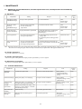
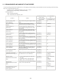
(1) Adjustment
Adjustment
Timing
Purpose
Tool
Approx.
time
Destination settings
(EEPROM settings)
At logic board replacement
To set the destination.
None.
Perform in the
service mode.
1 min.
Waste ink counter
resetting
(EEPROM settings)
- At logic board replacement
- At waste ink absorber
replacement
To reset the waste ink counter.
None.
Perform in the
service mode.
1 min.
Paper feed motor
position adjustment
At paper feed motor replacement
To adjust the belt tension. (Position the
paper feed motor so that the belt is
stretched tight.)
None.
5 min.
Grease application
- At carriage unit replacement
- At PS gear replacement
- To maintain sliding properties of the
carriage shaft.
- To protect the printer's sliding portions
(gears).
FLOIL KG-107A
1 min.
Ink system function
check
- At logic board replacement
- At platen unit replacement
- At carriage unit replacement
To maintain detection functionality for
None.
presence of the ink tanks and each ink tank Perform in the
position.
service mode.
1 min.
Note: DO NOT loosen the red screws at both ends of the carriage shaft, securing the print head position, as they are not re-adjustable.
The red screws securing the paper feed motor may be loosened only at replacement of the paper feed motor unit.
(2) Periodic maintenance
No periodic maintenance is necessary.
(3) Periodic replacement parts
There are no parts in this printer that require periodic replacement by a service engineer.
(4) Replacement consumables
There are no consumables that require replacement by a service engineer.
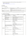
1-2. Customer Maintenance
Adjustment
Timing
Purpose
Tool
Approx.
time
Print head
alignment
At print head replacement.
To ensure accurate dot placement.
- Printer buttons
- Computer (automatic
settings via the printer
driver)
Print head cleaning
When print quality is not satisfying.
To improve nozzle conditions.
- Printer buttons
1 min.
- Computer (settings via the
printer driver)
Print head deep
cleaning
When print quality is not satisfying, and
not improved by print head cleaning.
To improve nozzle conditions.
Computer (settings via the
printer driver)
Ink tank
replacement
When an ink tank becomes empty. ("No
ink error" via the computer, or ink tank
LED flashing fast in red)
Paper feed roller
cleaning
When necessary
To clean the paper feed rollers.
Printer buttons
Bottom plate
cleaning
When the back side of the paper is
smeared
To clean the platen ribs.
- Plain paper
1 min.
- Computer (settings via the
printer driver) -----
1-1
-----
3 min.
2 min.
2 min.
2 min.
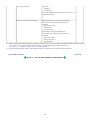
1-3. Product Life
(1) Printer
Specified print volume (I) or the years of use (II), whichever comes first.
(I) Print volume: 24,000 pages
Black 1,500 character pattern
13,600 pages
Color A4, 7.5% duty per color pattern
4,400 pages
3,600 pages
A4, photo, borderless printing
4 x 6, photo, borderless printing
600 pages
Postcard, photo, borderless printing
1,800 pages
(II) Years of use: 5 years of use
(2) Print head
Print volume: 24,000 pages
Black 1,500 character pattern
13,600 pages
Color A4, 7.5% duty per color pattern
4,400 pages
A4, photo, borderless printing
3,600 pages
4 x 6, photo, borderless printing
600 pages
Postcard, photo, borderless printing
1,800 pages
(3) Ink tank (target value)
Pattern
Ink tank used
Print yield
Black text
PGI-5BK
Approx. 800 pages
Color chart
PGI-5BK
Approx. 1,400 pages
CLI-8C
Approx. 710 pages
CLI-8M
Approx. 470 pages
CLI-8Y
Approx. 460 pages
PGI-5BK
Approx. 3,800 pages
CLI-8C
Approx. 380 pages
CLI-8M
Approx. 250 pages
Photo chart
CLI-8Y
Approx. 250 pages
Black text: When printing the Canon standard pattern (1,500 characters per page) on A4 size plain paper, with the default settings in the
Windows XP driver, using Word 2003.
Color chart: When printing the ISO/JIS-SCID N5 pattern on A4 size plain paper in bordered printing, with the default settings in the Windows
XP driver, using Photoshop 7.0.
Photo chart: When printing the Canon standard pattern on 4" x 6" Photo Paper Plus Glossy in borderless printing, with the default settings in
the Windows XP driver, using Windows XP Photo Printing Wizard.
The print yield in the table above is an average value measured in continuous printing, using the ink tank immediately after it is unsealed, until
the ink is out. Ink yield may vary depending on texts and photos printed, application software, print mode, and type of paper used.
When the machine is turned on and while printing, each ink may be used for protecting the print head and maintaining print quality.
1-2
1-4. Special Tools
Name
FLOIL KG-107A
Tool No.
QY9-0057-000
Application
To be applied to the sliding portions of the
carriage shaft, and printer's sliding portions
(gears).
Remarks
In common with the
S520.
1-5. Serial Number Location
On the carriage flexible cable holder (visible on the right of the carriage after the printer is turned on, the access cover is opened, and the carriage
moves to the center).
To the table of contents
To the top
<Part 1: 1. MAINTENANCE>
1-3
2. LIST OF ERROR DISPLAY / INDICATION
Errors are indicated by the LED, and warnings are displayed on the monitor of the computer connected to the printer.
2-1. Operator Call Errors (by Alarm LED Blinking in Orange)
Alarm LED
blinking in
orange
Error [Error code]
Solution
Remarks
2 times
No paper. (ASF) [1000]
Set the paper in the ASF, and
press the Resume/Cancel
button.
3 times
Paper jam. [1300]
Remove the jammed paper, and Error in paper feeding from the ASF.
press the Resume/Cancel button.
Paper output support error. [1300]
Remove any obstacles, if any,
from the paper output support,
and press the Resume/Cancel
button.
The first time the phenomenon occurs, it is indicated as the
paper output support error. The second time and thereafter
(such as when the phenomenon persists even after the
Resume/Cancel button is pressed), it is indicated as the PS
cam sensor error (service call error).
No ink. [1600]
Replace the empty ink tank(s),
or press the Resume/Cancel
button.
Pressing the Resume/Cancel button will exit the error
without ink tank replacement, however, ink may run out
during printing.
Ink tank not installed. [1660]
Install the applicable ink tank(s) properly, and confirm that the
LED's of all the ink tanks light
red.
4 times
5 times
The print head is not installed [1401], Install the print head properly.
or it is not properly installed (Print
head temperature sensor error
[1403] / Faulty EEPROM data of the
print head [1405]).
7 times
Multiple ink tanks of the same color
installed. [1681]
Replace the wrong ink tank(s)
with the correct one(s).
Ink tank in a wrong position. [1680]
Install the ink tank(s) in the
correct position.
8 times
Warning: The waste ink absorber
becomes almost full. [1700]
Pressing the Resume/Cancel
button will exit the error, and
enable printing.
9 times
The connected digital camera or
Remove the cable between the
digital video camera does not support camera and the printer.
Camera Direct Printing. [2001]
11 times
Failed in automatic print head
alignment. [2500]
13 times
The remaining ink amount unknown. An ink tank which has once
[1683]
been empty is installed. Replace
the applicable ink tank with a
new one.
14 times
Ink tank not recognized. [1684]
The service call error, indicating the waste ink absorber is
full, is likely to occur soon.
Press the Resume/Cancel
The error is indicated when the pattern is not printed due to
button.
no ink or non-ejection of ink, or when the sensor's AD
value is incorrect.
- If paper is being fed at error
occurrence, the error is
indicated after the paper is
ejected.
- If the error occurs, the print
head alignment values are not
changed.
- After exit from the error by the
Resume/Cancel button, the
automatic print head
alignment will not be re-done.
Printing with a once-empty or refilled ink tank can damage
the print head.
To continue printing without replacing the ink tank, press
the Resume/Cancel button for 5 sec. or longer to record the
use of a refilled ink tank.
Note:
After the above operation, the function to detect the
remaining ink amount is disabled.
A non-supported ink tank is
installed (the ink tank LED is
turned off). Install the supported
ink tanks.
1-4
15 times
Ink tank not recognized. [1410 to
1419]
An error occurred in an ink tank (the ink tank LED is turned off).
Replace the ink tank(s).
Access cover open. [1200]
Close the access cover.
2-2. Service Call Errors (by Cyclic Blinking in Orange (Alarm LED) and Green (Power LED), or Alarm LED Lit in
Orange)
Cycles of blinking
in orange (Alram
LED) and green
(Power LED)
2 times
Error [Error code]
Carriage error [5100]
Solution
(Replacement of listed parts, which are likely to be faulty)
- Carriage unit (QM2-3361)
- Timing slit strip film (QC1-8750)
- Logic board ass'y (QM2-3393 / QM3-1654)*1
- Carriage motor (QK1-1500)
3 times
Line feed error [6000]
- Timing sensor unit (QM2-2683)
- Timing slit disk film (QC1-4375)
- Feed roller ass'y (QL2-1291)
- Platen unit (QM2-3353)
- Logic board ass'y (QM2-3393 / QM3-1654)*1
- Paper feed motor (QK1-1996)
4 times
Purge cam sensor error [5C00]
- Purge unit (QM2-3370)
- Logic board ass'y (QM2-3393 / QM3-1654)*1
5 times
ASF (cam) sensor error [5700]
- Sheet feed unit (QM2-3367)
6 times
Internal temperature error [5400]
- Logic board ass'y (QM2-3393 / QM3-1654)*1
7 times
Waste ink absorber full [5B00]
- Ink absorber kit (QY5-0164)
8 times
Print head temperature rise error
[5200]
- Print head (QY6-0064)
9 times
EEPROM error [6800]
- Logic board ass'y (QM2-3393 / QM3-1654)*1
12 times
PG position error [5C10]
- Sheet feed unit (QM2-3367)
- Logic board ass'y (QM2-3393 / QM3-1654)*1
- Logic board ass'y (QM2-3393 / QM3-1654)*1
- Purge unit (QM2-3370)
13 times
AH position error [5710]
- Sheet feed unit (QM2-3367)
- Logic board ass'y (QM2-3393 / QM3-1654)*1
- Output support unit (QM2-3358)
- Output support gear unit (QM2-3359)
14 times
PS cam sensor error [5750]
- Sheet feed unit (QM2-3367)
- Logic board ass'y (QM2-3393 / QM3-1654)*1
- Output support unit (QM2-3358)
- Output support gear unit (QM2-3359)
15 times
USB Host VBUS overcurrent [9000]
- Logic board ass'y (QM2-3393 / QM3-1654)*1
16 times
Valve sensor error [6C00]
- Logic board ass'y (QM2-3393 / QM3-1654)*1
- Purge unit (QM2-3370)
17 times
Motor driver error [6D00]
- Logic board ass'y (QM2-3393 / QM3-1654)*1
19 times
Ink tank position sensor error [6502]
- Platen unit (QM2-3353)
- Logic board ass'y (QM2-3393 / QM3-1654)*1
20 times
Other hardware error [6500]
- Logic board ass'y (QM2-3393 / QM3-1654)*1
Continuous
alternate blinking
ROM error
- Logic board ass'y (QM2-3393 / QM3-1654)*1
Alarm LED lit
RAM error
- Logic board ass'y (QM2-3393 / QM3-1654)*1
1-5
*1: Before replacement of the logic board ass'y, check the waste ink amount (by service test print or EEPROM information print). If the waste
ink amount is 7% or more, also replace the ink absorber kit (QY5-0164) when replacing the logic board ass'y.
QM2-3393: iX5000 logic board ass'y
QM3-1654: iX4000 logic board ass'y
[See Section 3-3. Adjustment / Settings, (5) Service mode, for details.]
2-3. Warnings
Printer (no LED indications):
Displayed warning
Remarks
Low ink
Status indication only.
Print head temperature rise
If the print head temperature is high when the access cover is opened, the warning is
displayed*1.
When the print head temperature falls, the warning is released.
Protection of excess rise of the print head
temperature
If the print head temperature exceeds the specified limit, a Wait is inserted during
printing,
*1: If the warning is displayed, the carriage does not move to the ink tank replacement position when the access cover is opened.
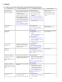
2-4. Troubleshooting by Symptom
Symptom
Faulty operation
Paper feed
problems
Solution
The power does not turn on.
The power turns off immediately after
power-on.
Replace the
- AC adapter, or
A strange noise occurs.
Remove foreign material, or attach a removed part if any.
Printing stops mid-way.
Replace the logic board ass'y*1.
Multiple sheets feed.
Replace the sheet feed unit.
Paper does not feed.
Remove foreign material, or replace the sheet feed unit.
Paper feeds at an angle.
Remove foreign material,
adjust the paper guide, or
replace the sheet feed unit.
No printing, or no color ejected.
Replace the
- ink tank,
- logic board ass'y*1.
- print head*2, or
- logic board ass'y*1,
remove foreign material from the purge unit caps, if any, or
replace the purge unit.
Printing is faint, or white lines appear on
Remove and re-install the print head, or replace the
printouts even after print head cleaning.
- ink tank,
Line(s) not included in the print data appears
- print head*2,
on printouts.
- purge unit, or
Unsatisfactory
print quality
- logic board ass'y*1.
Paper gets smeared.
Feed several sheets of paper,
perform bottom plate cleaning, or
clean the paper path with cotton swab or cloth.
A part of a line is missing on printouts.
Replace the
- ink tank, or
- print head*2.
Color hue is incorrect.
Replace the
- ink tank, or
- print head*2, or
perform print head alignment.
Printing is incorrect.
Replace the logic board ass'y*1.
1-6
Remarks
No ejection of black ink.
Replace the
- ink tank, or
- print head*2, or
remove foreign material from the purge unit caps, if any, or
replace the purge unit.
Graphic or text is enlarged on printouts.
When enlarged in the carriage movement direction,
clean grease or oil off the timing slit strip film, or
replace the
- timing slit strip film,
- carriage unit, or
- logic board ass'y*1.
When enlarged in the paper feed direction,
clean grease or oil off the timing slit disk film, or
replace the
- timing slit disk film,
- timing sensor unit, or
- logic board ass'y*1.
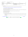
*1: Before replacement of the logic board ass'y, check the waste ink amount (by service test print or EEPROM information print). If the waste
ink amount is 7% or more, also replace the ink absorber kit (QY5-0164) when replacing the logic board ass'y.
[See Section 3-3. Adjustment / Settings, (5) Service mode, for details.]
*2: Replace the print head only after the print head deep cleaning is performed 2 times, and when the problem persists.
To the table of contents
To the top
<Part 1: 2. LIST OF ERROR DISPLAY / INDICATION>
1-7
3. REPAIR
3-1. Notes on Service Part Replacement (and Disassembling / Reassembling)
Notes on replacement*1
Adjustment / settings
- Before removal of the logic board
ass'y, remove the power cord, and
allow for approx. 1 minute (for
discharge of capacitor's
accumulated charges), to prevent
damages to the logic board ass'y.
- Before replacement, check the
waste ink amount (by service test
print or EEPROM information
print). If the waste ink amount is
7% or more, also replace the ink
absorber kit when replacing the
logic board ass'y.
[See 3-3. Adjustment / Settings,
(5) Service mode, for details.]
After replacement:
1. Initialize the EEPROM.
2. Reset the waste ink counter.
3. Set the destination in the
EEPROM.
4. Check the ink system function.
[See 3-3. Adjustment / Settings, (5)
Service mode, for details of 1 to 4]
5. Perform the print head alignment
in the user mode.
- EEPROM information print
- Service test print
- Printing via USB connection
- Direct printing from a digital
camera
Ink absorber kit
QY5-0164
After replacement:
1. Reset the waste ink counter.
[See 3.3. Adjustment / Settings, (5)
Service mode.]
- Service test print
Carriage unit
QM2-3361
- Service test print (Confirm ink
At replacement:
system function.)
1. Apply grease to the sliding
portions.
[See 3-3. Adjustment / Settings,
(2) Grease application.]
After replacement:
1. Check the ink system function.
[See 3.3. Adjustment / Settings,
(5) Service mode.]
Service part
Logic board ass'y
QM2-3393 (iX5000)
QM3-1654 (iX4000)
Operation check
- EEPROM information print
2. Perform the print head alignment
in the user mode.
Paper feed motor
QK1-1996
- The red screws securing the paper
feed motor are allowed to be
loosened. (DO NOT loosen any
other red screws.)
At replacement:
1. Adjust the paper feed motor.
[See 3-3. Adjustment / Settings, (1)
Paper feed motor adjustment.]
Platen unit
QM2-3353
- Service test print
After replacement:
1. Check the ink system function.
[See 3-3. Adjustment / Settings, (5)
Service mode.]
Platen unit: QM2-3353
- Replace the ink absorbers (QC1After replacement:
8876, QC1-8877) to the new ones, 1. After the platen unit is installed,
Carriage unit: QM2-3361
since they get torn in removal and
attach a new ink absorber to the
Feed roller ass'y
installation of the platen unit. platen unit and output support
Output support unit: QM2unit.
3358
[See 3-2. Special Notes on Repair
Servicing, (2) Platen unit removal
and reassembly.]
Purge unit: QM2-3370
- Attach the tube cover (QC2-2480) At replacement:
properly.
Waste ink tube: QC1-6458
1. To protect the waste ink tube
from being pinched when
Output support unit: QM2reassembling the printer unit
3358
chassis into the bottom case
unit, attach the tube cover.
[See 3-2. Special Notes on Repair
Servicing, (3) Printer unit
assembly.]
Timing slit strip film
QC1-6394
- Upon contact with the film, wipe
the film with ethanol.
- Confirm no grease is on the film.
- Service test print
After replacement:
1. Perform the print head alignment
in the user mode.
1-8
Timing slit disk film
QC1-6229
(Wipe off any grease thoroughly
with ethanol.)
- Do not bend the film.
Print head
QY6-0059
- Service test print
After replacement:
1. Perform the print head alignment
in the user mode.
*1: General notes:
- Make sure that the flexible cables and wires in the harness are in the proper position and connected correctly.
[See 3-2. Special Notes on Repair Servicing, (1) Flexible cable and harness wiring, connection, for details.]
- Do not drop the ferrite core, which may cause damage.
- Protect electrical parts from damage due to static electricity.
- Before removing a unit, after removing the power cord, allow the printer to sit for approx. 1 minute (for capacitor discharging to protect
the logic board ass'y from damages).
- Do not touch the timing slit strip film and timing slit disk film. No grease or abrasion is allowed.
- Protect the units from soiled with ink.
- Protect the housing from scratches.
- Exercise caution with the red screws, as follows:
i. The red screws of the paper feed motor may be loosened only at replacement of the paper feed motor unit (DO NOT loosen them
in other cases).
ii. DO NOT loosen the red screws on both sides of the main chassis, securing the carriage shaft positioning (they are not adjustable
in servicing).
To the table of contents
To the top
<Part 1: 3. REPAIR; 3-1. Notes on Service Part Replacement>
1-9
3-2. Special Notes on Repair Servicing
(1) Flexible cable and harness wiring, connection
Be cautious of wiring of the flexible cables and harness. Improper wiring or connection may cause breakage of a line, leading to ignition or
emission of smoke.
(I) Logic board ass'y wiring
(II) Paper feed motor side wiring
1-10
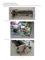
(2) Platen unit removal and reassembly
When the platen unit is removed from the printer unit, the ink absorbers* (QC1-8876, QC1-8877) will be cut. After the platen unit is
assembled into the printer unit, attach new ink absorbers.
* The ink absorbers transfer ink off the paper edge in borderless printing to the waste ink absorber in the bottom case, and they
are attached to the platen unit through to the output support unit.
When the platen unit is removed from the printer unit, the ink absorbers will be torn. To prevent possible ink leakage due to improper ink
flow via the torn absorbers, replace the ink absorbers to the new ones.
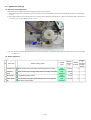
How to attach the ink absorbers:
(I) Along the folding line marked on the absorber (the red line in the photo below), fold the ink absorber so that the double-sided adhesive will
be the inside.
Ink absorbers folded
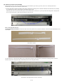
(II) Peel off the cover sheet from the adhesive tape, attach the ink absorber to the platen unit, and insert the remaining portion of the ink
absorber into the slot of the platen unit (indicated by the blue circle in the photo below).
Ink absorber on the right (same as the one on the left)
1-11
(III) Confirm that the ink absorbers come out from the slots under the output support unit (indicated by the blue circles in the photo below),
then peel off the adhesive cover sheet, and attach the ink absorbers to the output support unit as shown in the photo.
Ink absorbers attached to the output support unit
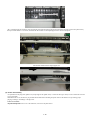
(3) Printer unit assembly
At replacement of the purge unit (QM2-3370), output support unit (QM2-3358), or waste ink tube (QC1-6458), be sure to attach the new tube
cover (QC2-2480).
Without the tube cover, the tube may be pinched and blocked when assembling the printer unit into the bottom case, preventing proper
purging, resulting in ink leakage or strange noise.
Tube cover location:
Align the left edge of the tube cover to the small slot, as shown in the photo below.
1-12
To the table of contents
To the top
<Part 1: 3. REPAIR; 3-2. Special Notes on Repair Servicing>
1-13
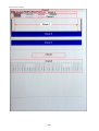
3-3. Adjustment / Settings
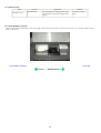
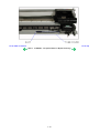
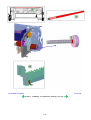
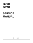
(1) Paper feed motor adjustment
Perform the following adjustments when the paper feed motor unit is replaced:
1) When attaching the motor, fasten the screws so that the belt is properly stretched (in the direction indicated by the blue arrow in the figure
below).
2) After replacement, be sure to perform the service test print, and confirm that no strange noise or faulty print operation (due to dislocation of
the belt or gear, or out-of-phase motor, etc.) occurs.
Note: The red screws securing the paper feed motor may be loosened only at replacement of the paper feed motor unit. DO NOT loosen them
in other cases.
(2) Grease application
No
1
2
3
4
Part name
Where to apply grease
Grease
name
Grease
amount
(mg)
Number
of
Number
locations
of drops*
to apply
grease
Chassis ass'y
Entire surface of the slide sheet where the gap lever contacts
Floil
KG107A
42 to 84
Carriage
shaft
Entire surface of the carriage shaft where the carriage unit slides
Floil
KG107A
270 to
530
PS gear B1
L Chassis B1 sliding portion
Floil
KG107A
9 to 18
1
1
Paper Guide
B1
Contact point of the paper guide and platen B1 on the opposite
side of the home position
Floil
KG107A
18 to 36
2
1
1-14
5
1
1
To the table of contents
To the top
<Part 1: 3. REPAIR; 3-3. Adjustment / Settings, (1) to (2)>
1-15
(3) Waste ink counter setting
When the logic board ass'y is replaced, reset the waste ink counter. In addition, according to the waste ink amount, replace the waste ink
absorber (ink absorber kit). The standard amount for waste ink absorber replacement is given in the table below.
Waste ink amount*1
Ink absorber kit replacement
Less than 7%
Not required.
7% or more
Required.
*1: Check the waste ink amount by service test print or EEPROM information print.
[See 3.3. Adjustment / Settings, (5) Service mode, for details.]
(4) User mode
Function
Procedures
Remarks
Print head manual cleaning
- Cleaning both black and color:
See "Standalone printer operation" below.
- Cleaning black or color separately, or both black and
color:
Perform from the printer driver Maintenance tab.
Print head deep cleaning
- Cleaning black or color separately, or both black and
color:
Perform from the printer driver Maintenance tab.
Paper feed roller cleaning
See "Standalone printer operation" below.
Nozzle check pattern printing
See "Standalone printer operation" below.
Also available from the printer driver
Maintenance tab.
Print head alignment
See "Standalone printer operation" below.
In Custom Settings of the printer driver
Maintenance tab, manual print head
alignment (by selecting the optimum values)
as with the conventional models can be
performed.
Bottom plate cleaning
Perform from the printer driver Maintenance tab.
Cleaning of the platen ribs when the
back side of paper gets smeared.
Print head replacement
The print head is replaceable at the same position
as for ink tank replacement. (Open the access
cover. When the carriage stops at the center, the
print head can be replaced.)
<Standalone printer operation>
1) Turn on the printer.
2) Press and hold the Resume/Cancel button until the Power LED blinks in green the specified number of times listed in the table below, and
release it. The operation starts.
Power LED
blinking
Operation
Remarks
1 time
Print head manual cleaning
2 times
Nozzle check pattern printing
3 times
Paper feed roller cleaning
4 times
Automatic print head alignment
Set a sheet of plain paper (A4 or letter) in the ASF.
5 times
Bottom plate cleaning
Fold a sheet of plain paper (A4 or letter) in half, then unfold and set
it in the ASF with the folded ridge facing down.
6 times
Unspecified
7 times
Head-to-paper distance setting to the widest
Set a sheet of plain paper (A4 or letter) in the ASF.
8 times or more Unspecified
(5) Service mode
Function
Service test print
- Model name
- Destination
- ROM version
Procedures
Remarks
See "Service mode operation procedures"
below.
1-16
Set a sheet of A3 or LDR size paper.
For print sample, see 3-4. Verification Items, (1)
Service test print, <Service test print sample>.
- USB serial number
- Waste ink amount
- Ink system function check
result
EEPROM initialization
See "Service mode operation procedures"
below.
The following items are NOT initialized, and the
shipment arrival flag is not on:
- USB serial number
- Destination settings
- Waste ink counter
Waste ink counter reset
See "Service mode operation procedures"
below.
If the waste ink amount is 7% or more, replace the
ink absorber kit.
Destination settings
See "Service mode operation procedures"
below.
Note: At the end of the service mode, press the Power button. The paper lifting plate of the sheet feed unit will be raised.
<Service mode operation procedures>
1) With the printer power turned off, while pressing the Resume/Cancel button, press and hold the Power button. (DO NOT release the
buttons. The Power LED lights in green to indicate that a function is selectable.)
2) While holding the Power button, release the Resume/Cancel button. (DO NOT release the Power button.)
3) While holding the Power button, press the Resume/Cancel button 2 times, and then release both the Power and Resume/Cancel buttons.
(Each time the Resume/Cancel button is pressed, the Alarm and Power LEDs light alternately, Alarm in orange and Power in green,
starting with Alarm LED.)
4) When the Power LED lights in green*1, press the Resume/Cancel button the specified number of time(s) according to the function listed in
the table below. (Each time the Resume/Cancel button is pressed, the Alarm and Power LEDs light alternately, Alarm in orange and Power
in green, starting with Alarm LED.)
Time(s)
LED indication
0 times
Green (Power)
Power off
When the print head is not installed, the carriage returns
and locks in the home position capped.
1 time
Orange (Alarm)
Service test print
See 3-4. Verification Items, (1) Service test print.
2 times
Green (Power)
EEPROM information print
See 3-4. Verification Items, (2) EEPROM information
print.
3 times
Orange (Alarm)
EEPROM initialization
4 times
Green (Power)
Waste ink counter resetting
5 times
Orange (Alarm)
Destination settings
After entering the destination settings mode, press the
Resume/Cancel button the specified number of time(s) to
select the destination. For detail, see "Destination settings
procedures" below.
6 times
Green (Power)
Print head deep cleaning
(Cleaning of both black and color)
7 times
Orange (Alarm)
Reserved
8 to 13 times
Green at even
numbers (Power)
Orange at odd
numbers (Alarm)
Return to the menu selection
14 times
15 to 21
times*2
Green (Power)
Green at even
numbers (Power)
Orange at odd
numbers (Alarm)
Function
Remarks
Reserved
Return to the menu selection
*1: If the LED does not light in green (the printer does not enter the service mode), disconnect the power cord and plug it again. Then start
from step 1) to start the printer in the service mode again.
If the automatic power-on function is enabled in the printer, the printer enters the service mode for the first time, but it will never enter
the service mode if the printer is turned off by the Power button. This is because the printer remains to be turned on internally if the
power is turned off by the Power button. To prevent this, disconnection of the power cord is required before starting the printer in the
service mode.
*2: If the Resume/Cancel button is pressed 22 or more times, the Alarm or Power LED lights steadily without any changes.
1-17
<Destination settings procedures>
In the destination settings mode, press the Resume/Cancel button the specified number of time(s) according to the destination listed in the table
below, and press the Power button.
Time(s)
LED indication
Destination
0 times
Green (Power)
No change of the destination
1 time
Orange (Alarm)
Japan
2 times
Green (Power)
Korea
3 times
Orange (Alarm)
US
4 times
Green (Power)
Europe
5 times
Orange (Alarm)
Australia
6 times
Green (Power)
Asia
7 times
Orange (Alarm)
China
8 times
Green (Power)
Taiwan
9 times or more
Orange (Alarm)
Return to the menu selection
Note: After setting the destination, confirm the model name and destination in service test print or EEPROM information print.
[See 3.4. Verification Items, (1) Service test print, or (2) EEPROM information print.]
To the table of contents
To the top
<Part 1: 3. REPAIR; 3-3. Adjustment / Settings, (3) to (5)>
1-18
3-4. Verification Items
(1) Service test print
<EEPROM information contents>
On the service test print (sample below), confirm the EEPROM information as shown below. (The information is given in the upper portion of
the printout.)
iX5000 (iX4000): Model name
JPN: Destination
Vx.xx: ROM version
USB (xxxxxx): USB serial number
FA = xx xx xx: Reserved for plant use
D = xxx.x: Waste ink amount (%)
AB (C = OK Y = ...): Ink system check result
Note: The waste ink amount should be confirmed by EEPROM information print (not by service test print).
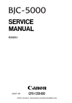
<Print check items>
On the service test print (sample below), confirm the following items:
- Check 1, top of form accuracy: The lines shall not extend off the paper.
- Check 2, EEPROM information
- Check 3, nozzle check pattern: Ink shall be ejected from all nozzles.
- Check 4, check pattern for uneven printing due to line feeding: There shall be no remarkable streaks or unevenness.
- Check 5, check pattern for uneven printing due to carriage movement (standard mode): There shall be no remarkable unevenness.
- Check 6, check pattern for uneven printing due to carriage movement (highest print quality mode): There shall be no remarkable
unevenness.
- Check 7, check pattern for paper thickness lever operation: The line shall slide at the center.
- Check 8, check pattern for straight line and carriage accuracy: There shall be no misalignment or breakage of the lines.
1-19
<Service test print sample>
1-20
(2) EEPROM information print
<How to read EEPROM information print>
Print sample:
iX5000 JPN V1.04 IF(USB2=1) D=004.5 ST=2005/12/27-18:30
ER(ER0=1000 ER1=5100) LPT=2006/02/09-09:09
PC(M=002 R=000 T=001 D=009 C=009)
CLT(BK=2006/02/25-18:30 CL=2006/02/25-18:30)
CH=00002 CT(PBK=040 C=109 M=012 Y=113) IS(PBK=1 C=1 M=1 Y=1)
P_ON(S=00009) A_REG=1 M_REG=0
UR(A(BKoe)=000 B(Coe)=000 C(Moe)=000 D(SCoe)=000 E(SMoe)=000
F(BKbi)=000 G(CLbi)=000 H(BK-CL)=000 I(SCLbi)=000 J(C-SC)=000 K(S-SM)=000
L(NZctr)=000 M(NZedge)=000
WP=0024 CDIN(PB=000) MSD(015)
PAGE(All=00083 PP=00035 HR+MP=00003 PR+SP+SG =00000 GP =00000 PC=00000 EV=00000)
CDPAGE(All=00000 A3=00000 A4=00000) EDGE=(All=00000 A3=00000 A4=00000)
SIZE=(A3=00020 A4=00050) 2L=00000) L=00000 PC=00013)
Head TempBK=18.5 Head TempC=17.5 Env Temp=30.0 FF(3F 3F 3F)
HDEEPROM
V0001 SN=0318-A43D
LN(00000 00000 00001 00003 00001 00000 00000) ID=00
IL=(PBK=000 BK=000 Y=001 M=001 M2=001 C=000 C2=001)
Printed items:
1. Model name 2. ROM version 3. Connected I/F (USB2) 4. Waste ink amount 5. Installation date
6. Operator call/service call error record 7. Last printing time
8. Purging count (manual/deep cleaning/timer/dot count/ink tank replacement)
9. Cleaning time (BK/CL)
10. Print head replacement count 11. Ink tank replacement count (PBK/Y/M/C) 12. Ink status (PBK/Y/M/C)
13. Power-on count (soft) 14. Automatic print head alignment by user 15. Manual print head alignment by user
16. User print head alignment values (Bkoe/Coe/Moe/SCoe/SMoe/ Bkbi/CLbi/BK-CL/SCLbi/C-SC/M-SM/ NZctr/NZedge)
17. Wiping count 18. Camera Direct Print-supported device connection record 19. Longest period where printing stops
20. ASF feed pages (total, plain paper, High Resolution Paper & Matte Photo Paper, Photo Paper Pro & Photo Paper Plus Glossy & Photo
Paper Plus Semi-gloss, Glossy Photo Paper, postcard, envelope)
21. Camera Direct print pages (total, A3, A4) 22. Borderless print pages (total, A3, A4)
23. Print pages by paper size (A3, A4, 5x6, 4x6, postcard)
24. Print head temperature (BK/CL) 25. Inside temperature 26. Line inspection information
HDEEPROM
27. Version 28. Serial number
29. Lot number 30. Print head ID
31. Ink ejection level (PBK, Y, M, M2, C, C2)
To the table of contents
To the top
<Part 1: 3. REPAIR; 3-4. Verification Items>
1-21
4. PRINTER TRANSPORTATION
This section describes the procedures for transporting the printer for returning after repair, etc.
1) In the service mode, press the Power button to finish the mode, and confirm that the paper lifting plate of the sheet feed unit is raised.
2) Keep the print head and ink tanks installed in the carriage.
[See Caution 1 below.]
3) Turn off the printer to securely lock the carriage in the home position. (When the printer is turned off, the carriage is automatically locked
in place.)
[See Caution 2 below.]
Caution:
(1) If the print head is removed from the printer and left alone by itself, ink (especially the pigment black ink) is likely to dry. For this
reason, keep the print head installed in the printer even during transportation.
(2) Securely lock the carriage in the home position, to prevent the carriage from moving and applying stress to the carriage flexible cable,
or causing ink leakage, during transportation.
Memo:
If the print head must be removed from the printer and transported alone, perform the following:
(1) Attach the protective cap (used when the packing was opened) to the print head (to protect the print head face from damage due to
shocks).
To the table of contents
To the top
<Part 1: 4. PRINTER TRANSPORTATION>
1-22
Part 2
TECHNICAL REFERENCE
1. NEW TECHNOLOGIES
(1) New ink tank system (PGI-5, CLI-8)
An LED is installed in each ink tank.
By the LED indication, wrong installation of the ink tanks will be prevented, and the remaining ink level can be visually recognized with the
ink tanks seated in the carriage.
The combination of the new pigment-based black ink with higher resistance against bleeding or marker pens and the new dye-based inks with
higher photo quality and weather resistance makes the new ink system strong in both photo and text printing.
(2) Super-photo quality printing
By the FINE technologies, 2 pl of ultra-fine ink droplet is adopted. The iX5000 / iX4000 provides excellent super-photo
print quality without graininess at the maximum resolution of 4,800 dpi x1,200 dpi*1, which is equal to that of a 6-color
printer.
*1: Printing at the minimum distance of 1/4800 inch between the dots.
(3) Speed
Approx. 42 sec. in 4 x 6 borderless printing (standard mode, Photo Paper Pro, Full Page SCID No.2)
For reference:
iX5000: 25 ppm in monochrome print and 17 ppm in color print
iX4000: 18 ppm in monochrome print and 14 ppm in color print
(4) Direct Printing Function
The Camera Direct Print standard, PictBridge, is supported.
The Bubble Jet Direct is not supported..
(5) USB 2.0 Hi-Speed supported
The iX5000 / iX4000 supports USB 2.0 Hi-Speed, enabling high speed data transfer in use with the computer, OS, and USB hub. However,
the parallel I/F (IEEE1284) is removed.
(6) Borderless printing supported (iX4000)
The iX4000 supports borderless printing, which the i6100 (the least-expensive in the existing A3 models) does not support.
To the table of contents
To the top
<Part 2: 1. NEW TECHNOLOGIES>
2-1
2. CLEANING MODE AND AMOUNT OF INK PURGED
To prevent printing problems due to bubbles, dust, or ink clogging, print head cleaning is performed before the start of printing (when the cleaning
flag is on), except in the following cases:
- Cleaning on arrival: Performed when the access cover is closed.
- Manual cleaning / deep cleaning: Performed manually.
<Cleaning mode list>
Black: Pigment-based black
Color: Dye-based cyan, magenta, yellow
Condition
Amount of ink used (g)
Est. required time
(sec.)
(in the normal
temperature/humidity (not including the time
of opening the caps)
environment)
Details
On arrival of the printer
(All in sequence)
First to third cleaning after shipped from the
plant.
0.65 (Black)
1.54 (Color)
85
Dot count cleaning
When the specified number of dots are
printed since the previous Black cleaning.
0.20 (Black)
35 (Black)
0.20 (Black)
35 (Black)
(Black only)
If 24 to 60 hours have elapsed since the
previous Black cleaning till the start of the
next printing.
Timer cleaning - 1
(Black only)
If 60 to 120 hours have elapsed since the
previous Black cleaning till the start of the
next printing.
Timer cleaning - 2*2
If 120 to 336 hours have elapsed since the
previous Black/Color cleaning till the start of
the next printing.
0.20 (Black)
0.60 (Color)
35 (Black)
40 (Color)
Timer cleaning - 3
(All in sequence)
If 336 to 1,080 hours have elapsed since the
previous Black/Color cleaning till the start of
the next printing.
0.65 (Black)
1.07 (Color)
70
Timer cleaning - 4
(All in sequence)
If 1,080 to 2,160 hours have elapsed since the 1.08 (Black)
previous Black/Color cleaning till the start of 1.07 (Color)
the next printing.
70
Timer cleaning - 5
(All in sequence)
If 2,160 to 4,320 hours have elapsed since the 2.02 (Black)
previous Black/Color cleaning till the start of 1.07 (Color)
the next printing.
70
Timer cleaning - 6
(All in sequence)
If 4,320 or longer hours have elapsed since
the previous Black/Color cleaning till the
start of the next printing.
2.02 (Black)
1.07 (Color)
70
At print head replacement
(All in sequence)
When the print head is removed and installed. 0.65 (Black)
1.54 (Color)
85
At ink tank replacement*3
When an ink tank is replaced (without the
print head removal or re-installation)
0.40 (Black)
1.07 (Color)
65 (All in sequence)
35 (Black)
55 (Color)
(Black/Color/All at the same
time)
- Via the operation panel (All at the same
time only)
- Via the printer driver (Selectable from
Black, Color, or All at the same time)
0.20 (Black)
0.60 (Color)
35 (All at the same
time)
30 (Black)
30 (Color)
Deep cleaning
Via the printer driver (Selectable from Black,
Color, or All at the same time)
2.02 (Black)
1.07 (Color)
75 (All at the same
time)
40 (Black)
55 (Color)
0.40 (Black)
1.07 (Color)
65 (All in sequence)
(Black)
Timer cleaning - 0*1
(Black/Color)
(Black/Color/All in sequence)
Manual cleaning
(Black/Color/All at the same
time)
If the print head has not been
capped before power-on
(All in sequence)
2-2
*1: When 24 to 60 hours have elapsed since the previous Black cleaning, timer cleaning - 0 is performed. However, this cleaning will
be conducted up to 5 times from the printer installation, and no further timer cleaning - 0 will be performed.
*2: The period of time since the previous cleaning is counted by Black and Color separately. For this reason, the cleaning mode may
differ according to Black or Color.
*3: If a black ink is removed for 10 seconds or longer, Black cleaning is performed.
If one of the color ink tanks is removed for 60 seconds or longer, Color cleaning is performed.
(Cleaning is performed according to the period of time an ink tank is removed from the print head, regardless of whether the ink
tank is actually replaced or not. If the same ink tank is removed and installed back multiple number of times, cleaning is
performed based on the accumulated period of time the ink tank is removed.)
In the above condition, when only the black ink tank is removed, Black cleaning is performed. When one of the color ink tanks is
removed, Color cleaning is performed. Both the black and color ink tanks are removed, All-at-the-same-time cleaning is
performed.
To the table of contents
To the top
<Part 2: 2. CLEANING MODE AND AMOUNT OF INK PURGED>
2-3
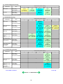
3. PRINT MODE
Default setting
Selectable in the printer driver Main tab
Selectable after clicking Custom in the Main tab
Ink used
Print control
BK:
C:
M:
Y:
PGI-5BK
CLI-8C(5pl)
CLI-8M(5pl)
CLI-8Y(5pl)
c:
m:
CLI-8C(2pl)
CLI-8M(2pl)
Bi
Uni
Bi-directional
Uni-directional
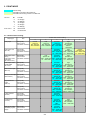
3-1. Normal Color Printing
Paper type
Item
Printer driver Custom setting
5
4
3
2
Custom
1pass, Bi
BK : 300x300
YMC :600x600
Fast
1pass, Bi
BK : 300x300
YMC : 600x600
Standard
1pass, Bi
BKY : 600x600
MC : 1200x1200
High
4passes, Bi
BK : 600x600
YMCmc :
1200x1200
Plain paper
Print quality
Print contorol
Ink used & resolution
Photo Paper Pro
(PR-101)
Print quality
Print contorol
Ink used & resolution
Photo Paper Plus
Glossy
Photo Paper Plus
Semi-gloss
(PP-101/SG-101)
Print quality
Print contorol
Ink used & resolution
Fast
Standard
High
3passes, Bi
4passes, Bi
6passes, Bi
YMC : 1200x1200 YMC : 1200x1200 YMC : 1200x1200
mc : 1200x1200 mc : 1200x1200
mc : 1200x1200
Photo Paper Plus
Double sided
(PP-101D)
Print quality
Print contorol
Ink used & resolution
Standard
High
4passes, Bi
6passes, Bi
YMC : 1200x1200 YMC : 1200x1200
mc : 1200x1200
mc : 1200x1200
Matte Photo Paper
(MP-101)
Print quality
Print contorol
Ink used & resolution
Standard
High
4passes, Bi
6passes, Bi
YMC : 1200x1200 YMC : 1200x1200
mc : 1200x1200
mc : 1200x1200
Glossy Photo Paper Print quality
(GP-401/501)
Print contorol
Ink used & resolution
Standard
High
4passes, Bi
6passes, Bi
YMC : 1200x1200 YMC : 1200x1200
mc : 1200x1200
mc : 1200x1200
High Resolution
Paper
(HR-101)
Print quality
Print contorol
Ink used & resolution
Standard
High
4passes, Bi
6passes, Bi
YMC : 1200x1200 YMC : 1200x1200
mc : 1200x1200
mc : 1200x1200
Envelope
Print quality
Print contorol
Ink used & resolution
Standard
3passes, Bi
BKY : 600x600
MC : 1200x600
T-Shirt Transfer
(TR-301)
Print quality
Print contorol
Ink used & resolution
Standard
6passes, Bi
YMC : 1200x1200
Transparency
(CF-102)
Print quality
Print contorol
Ink used & resolution
Standard
2passes, Bi
BK : 600x600
YMC :
1200x1200
Other photo paper
(swellable polymer
paper)
Print quality
Print contorol
Ink used & resolution
Standard
8passes, Bi
YMC : 1200x1200
mc : 1200x1200
1
Standard
High
Custom
4passes, Bi
6passes, Bi
16passes, Bi
YMC : 1200x1200 YMC : 1200x1200 YMC : 2400x1200
mc : 1200x1200
mc : 1200x1200
mc : 4800x1200
2-4
High
4passes, Bi
BK : 600x600
YMCmc:1200x1200
High
6passes, Bi
BK : 600x600
YMC : 1200x1200
3-2. Normal Grayscale Printing
Paper type
Item
Plain paper
Print quality
Print contorol
Ink used & resolution
Envelope
Print quality
Print contorol
Ink used & resolution
Printer driver Custom setting
5
4
3
2
Custom
1pass, Bi
BK : 300x300
Fast
1pass, Bi
BK : 300x300
Standard
1pass, Bi
BK : 600x600
High
4passes, Bi
BK:600x600
Standard
2passes, Uni
BK : 600x600
High
4passes, Uni
BK : 600x600
1
3-3. Borderless Printing
Paper type
Item
Printer driver Custom setting
5
4
3
2
1
Plain paper
Print quality
Print contorol
Ink used & resolution
Standard
2passes, Bi
Y : 600x600
MC : 1200X1200
Photo Paper Pro
(PR-101)
Print quality
Print contorol
Ink used & resolution
Standard
High
Custom
4 pass, Bi
6passes, Bi
16passes, Bi
YMC: 1200x1200 YMC : 1200x1200 YMC : 2400x1200
mc : 1200x1200
mc : 1200x1200
mc : 4800x1200
Matte Photo Paper
(MP-101)
Print quality
Print contorol
Ink used & resolution
Standard
High
4passes, Bi
6passes, Bi
YMC : 1200x1200 YMC : 1200x1200
mc : 1200x1200
mc : 1200x1200
Photo Paper Plus
Glossy
Photo Paper Semigloss
(PP-101/SG-101)
Print quality
Print contorol
Ink used & resolution
Fast
Standard
High
3passes, Bi
4passes, Bi
6passes, Bi
YMC : 1200x1200 YMC : 1200x1200 YMC : 1200x1200
mc : 1200x1200
mc : 1200x1200
mc : 1200x1200
Glossy Photo Paper
(GP-401/501)
Print quality
Print contorol
Ink used & resolution
Standard
High
4passes, Bi
6passes, Bi
YMC : 1200x1200 YMC : 1200x1200
mc : 1200X1200 mc : 1200x1200
Photo Paper Plus
Double sided
(PP-101D)
Print quality
Print contorol
Ink used & resolution
Standard
High
4passes, Bi
6passes, Bi
YMC : 1200x1200 YMC :1200x1200
mc : 1200x1200
mc : 1200x1200
3-4. Camera Direct Printing
Paper type
Item
Printer driver Custom setting
5
4
3
2
Plain paper
Print quality
Print contorol
Ink used & resolution
High
4passes, Bi
BK :600x600
YMCmc :
1200x1200
Photo Paper Pro
(PR-101)
Print quality
Print contorol
Ink used & resolution
High
6 ass, Bi
CMY : 1200x1200
mc : 1200x1200
Photo Paper Plus
Glossy
Photo Paper Plus
Semi-gloss
(PP-101/SG-101)
Print quality
Print contorol
Ink used & resolution
High
6passes, Bi
CMY : 1200x1200
mc : 1200x1200
To the table of contents
1
To the top
<Part 2: 3. PRINT MODE>
2-5
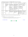
4. FAQ (Problems Specific to the iX5000 / iX4000 and Corrective Actions)
No.
1
*
Function
Phenomenon
Cause
Soiling on the
- After continuous
back side of paper
borderless printing of
(lines or streaks
small sized paper (such
parallel to the
as 4 x 6), when a larger
paper feed
sized paper (such as A4)
direction)
is printed.
- With Photo Paper Plus
A Print results
Double Sided or
postcards, the
phenomenon is likely to
be noticeable and to be
complained of by users,
as printing is performed
on both sides of such
paper.
Carriage error
during setup
2
Condition
C
Setup
- The protective material is
not removed from inside
the printer, when the
printer is turned on.
Corrective action
Possible call or
complaint
In borderless printing,
1. Perform Bottom plate - Paper gets
printing is performed to
cleaning (from the
smeared.
the size slightly larger
printer driver) up to - The back side of
than the paper size, and
3 times*1.
paper gets
ink off the paper is
2. If soiling on the paper smeared.
absorbed by the platen's
still remains after 3
ink absorber. Absorbed
times of Bottom
ink may attach to the
plate cleaning, wipe
platen rib(s) after
the platen rib(s) and
several dozen sheets are
their surroundings
printed, causing soiling
with a cotton swab.
at the leading edge of
paper or on the back
side of paper.
A user missed the step
to remove the protective
material which is given
in the Easy Setup
Instructions.
While following the
- An error occurs.
instructions in the Easy - The Power and
Setup Instructions, pull
Alarm lamps
the tape to remove the
alternately blink 2
right and left protective
times.
material, then turn the
A
strange noise is
printer off and turn it on
heard.
again.
*1: Change the paper in each Bottom plate cleaning. The cleaning can end when paper does not get any soiling.
* Occurrence level:
A: The symptom is likely to occur frequently. (Caution required)
B: The symptom may occur under certain conditions, but likeliness is assumed very low in practical usage.
C: The symptom is unlikely to be recognized by the user, and no practical issues are assumed.
To the table of contents
To the top
<Part 2: 4. FAQ>
2-6
Part 3
APPENDIX
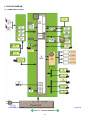
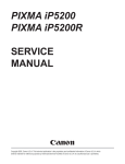
1. BLOCK DIAGRAM
1-1. PIXMA iX5000 / iX4000
To the table of contents
To the top
<Part 3: 1. BLOCK DIAGRAM>
3-1
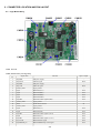
2. CONNECTOR LOCATION AND PIN LAYOUT
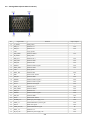
2-1. Logic Board Ass'y
CN101 Not used
CN201 (Print head 1/2 [Carriage unit])
Signal name
No.
Function
Input / Output
1
AB_PWR
AB power supply
-
2
AB_DATA
AB data signal
3
AB_PWR
AB power supply
4
AB_CLK
AB clock signal
5
LOGIC_GND
Logic ground
6
H_D3
Head data (SC1)
OUT
7
H_D0
Head data (BK1)
OUT
8
H_D1
Head data (BK2)
OUT
9
H_D5
Head data (SM1)
OUT
10
H_ENB0
Head heat enable signal 0 (BK)
OUT
11
LOGIC_GND
Logic ground
12
DIA0
Diode sensor anode 0
13
LOGIC_GND
Logic ground
14
H_D2
Head data (C1)
OUT
15
H_D4
Head data (M1)
OUT
16
H_ENB3
Head heat enable signal 3 (SCol)
OUT
17
H_D8
Head data (Y1)
OUT
18
H_ENB1
Head heat enable signal 1 (Col-1)
OUT
19
H_LATCH
Head data latch signal
OUT
20
H_EEPROM_CS
Head EEPROM chip select signal
OUT
BUS
BUS
-
IN
-
3-2
21
H_EEPROM_SK
Head EEPROM serial clock signal
OUT
22
H_D10
Head data (SM2)
OUT
23
LOGIC_GND
Logic ground
24
H_CLK
Head data transfer clock signal
OUT
25
H_EEPROM_DIO
Head EEPROM data signal
OUT
26
H_D12
Head data (SC2)
OUT
27
H_D6
Head data (PBK1)
OUT
28
LOGIC_GND
Logic ground
29
CR_ENCB
Carriage encoder phase B
30
LOGIC_GND
Logic ground
31
CR_ENCA
Carriage encoder phase A
32
LOGIC GND
Logic ground
33
DIA1
Diode sensor anode 1
34
LOGIC GND
Logic ground
35
H_D7
Head data (PBK2)
OUT
36
H_D11
Head data (M2)
OUT
37
H_D9
Head data (Y2)
OUT
38
H_D13
Head data (C2)
OUT
39
SNS_CDR_P
CDR position sensor signal (not used)
40
THERMO
Carriage temperature sensor signal
41
DIK
DIK (Logic ground)
42
H_ENB2
Head heat enable signal 2 (Col-2)
43
VSEN_CDRS
Power supply for CDR sensor (not used)
44
VSEN_3.3V
Power supply for sensor 3.3V
45
LOGIC GND
Logic ground
-
IN
IN
IN
-
IN
OUT
OUT
-
CN202 (Print head 2/2 [Carriage unit])
No.
Signal name
Function
1 to 3
H_GND
Head ground
4 to 6
HVH_24V
Head drive power supply 24V
Input / Output
OUT
7 to 10 H_GND
Head ground
-
11to 12 HVH_16V
Head drive power supply 16V
OUT
13 to 16 HVH_24V
Head drive power supply 24V
OUT
17
LOGIC_GND
Logic ground
-
18
HVDD_3.3V
Head logic drive power supply 3.3V
19
LOGIC_GND
Logic ground
20
HVDD_3.3V
Head logic drive power supply 3.3V
OUT
OUT
CN301 (AC adapter)
No.
Signal name
Function
Input / Output
1
VH1
Head power supply
2
H1_GND
Head ground
IN
3
VM
Motor power supply
IN
4
VM
Motor power supply
IN
5
M_GND
Motor ground
6
PW_CONT
Power supply control signal
-
-
3-3
OUT
CN302 (USB I/F)
No.
Signal name
Function
Input / Output
1
SNS_USB
USB: VBUS power supply sense
IN
2
D-
USB: D- signal
BUS
3
D+
USB: D+ signal
BUS
4
GND
Ground
-
5 to 9
GND
Ground
-
CN303 (DSC harness)
No.
Signal name
Function
Input / Output
1
GND
Ground
-
2
GND
Ground
-
3
D+
DSC-USB: D+ signal
BUS
4
D-
DSC-USB: D- signal
BUS
5
PWR
DSC-USB: VBUS signal
OUT
CN402 (Sensor multi 1 harness)
No.
Signal name
Function
1
VSEN_3.3V
Power supply for sensor 3.3V
2
GND
Ground
3
SNS_PF_PE
PF/PE sensor
4
GND
Ground
5
APCL_ENCA
APCL encoder phase A
6
VSEN_3.3V
Power supply for sensor 3.3V
7
APCL_ENCB
APCL encoder phase B
8
GND
Ground
9
PF_ENCA
PF encoder phase A
10
VSEN_3.3V
Power supply for sensor 3.3V
11
PF_ENCB
PF encoder phase B
Input / Output
OUT
IN
IN
OUT
IN
IN
OUT
IN
CN403 (Operation panel ass'y)
No.
Signal name
Function
Input / Output
1
RESUME_SW
Resume/Cancel button switch
IN
2
LED_BIN1
Bin 1 LED display (not used)
-
3
LED_RESUME
(ORANGE)
Resume/Cancel LED display
OUT
4
LED_BIN2
Bin 2 LED display (not used)
-
5
POW_SW
Power button switch
IN
6
BIN_SW
Bin switch (not used)
-
7
LED_POWER(GREEN) Power LED display
8
GND
Ground
9
SNS_FRONT_CVR
Front cover sensor
10
AB_POW
Power supply for AB
OUT
IN
OUT
3-4
11
DOOR
Door sensor
IN
12
AB_SNS
AB sensor
IN
13
INK_CDRS_PWM
CD-R LED control signal (not used)
14
SNS_INKS
Ink sensor
IN
CN404 (PE sensor / LF encoder harness)
No.
Signal name
Function
1
VSEN_3.3V
Power supply for sensor 3.3V
2
GND
Ground
3
SNS_PE
Paper empty sensor
4
GND
Ground
5
LF_ENCA
LF encoder phase A
6
VSEN_3.3V
Power supply for sensor 3.3V
7
LF_ENCB
LF encoder phase B
Input / Output
OUT
IN
IN
OUT
IN
CN408 (Main_cam)
No.
Signal name
Function
1
VSEN_3.3V
Power supply for sensor 3.3V
2
GND
Ground
3
SNS_MAIN_CAM
Main cam sensor
Input / Output
OUT
IN
CN501 (Motor multi harness)
No.
Signal name
Function
Input / Output
1
CR_M
CR motor +
OUT
2
CR_MN
CR motor -
OUT
3
PF_MN
PF motor -
OUT
4
PF_M
PF motor +
OUT
5
AP_M
AP motor +
OUT
6
AP_MN
AP motor -
OUT
7
LF_M
LF motor +
OUT
8
LF_MN
LF motor -
OUT
To the table of contents
To the top
<Part 3: 2. CONNECTOR LOCATION AND PIN LAYOUT; 2-1. Logic Board Ass'y>
3-5
2-2. Carriage Board (Print Head Connector)
Signal name
No.
Function
Input / Output
1, 2
A_GNDH
Head ground
-
3
HD2_C1
Head data C1
OUT
4
HD8_Y1
Head data Y1
OUT
5
VSS
Logic ground
-
6
HD6_PBK1
Head data PBK1
7, 8
B_GNDH
Head ground
9
HD3_SC1
Head data SC1
OUT
10
HD5_SM1
Head data SM1
OUT
11
HD4_M1
Head data M1
OUT
12
HENB1
Head heat enable signal 1
OUT
13
HD10_SM2
Head data SM2
OUT
14
VSS
Logic ground
-
15
HD11_M2
Head data M2
OUT
16
DIK
Diode sensor cathode
17
HD0_K1
Head data BK1
OUT
18
HENB0
Head heat enable signal 0
OUT
19
HENB3
Head heat enable signal 3
OUT
20
HLAT
Head data latch signal
OUT
21
HD12_SC2
Head data SC2
OUT
22
HD7_PBK2
Head data PBK2
OUT
23
HD9_Y2
Head data Y2
OUT
24
HENB2
Head heat enable signal 2
OUT
25
HD1_K2
Head data BK2
OUT
26
DIA0
Diode sensor anode 0
27
HVDD_3.3V
Head logic power supply 3.3V
OUT
28
ROM_CS
Head EEPROM chip select signal
OUT
29
HCLK
Head clock signal
OUT
30
ROM_DIO (O)
Head EEPROM data signal
31
HD13_C2
Head data C2
OUT
32
B_VH_16V
Head drive power supply 16V
OUT
OUT
-
IN
IN
IN
3-6
33,34
A_VH_24V
Head drive power supply 24V
OUT
35
HVDD_3.3V
Head logic power supply 3.3V
OUT
36
ROM_SK
Head EEPROM serial clock signal
OUT
37
ROM_DIO (I)
Head EEPROM data signal
OUT
38
DIA1
Diode sensor anode 1
39
VHT
Head drive power supply 24V
OUT
40
B_VH_24V
Head drive power supply 24V
OUT
IN
To the table of contents
To the top
<Part 3: 2. CONNECTOR LOCATION AND PIN LAYOUT; 2-2. Carriage Board>
3-7
3. PIXMA iX5000 / iX4000 Specifications
<Printer>
Type
Desktop serial color bubble jet printer
Paper feeding
method
Auto sheet feed
Resolution
4,800 x 1,200dpi (Max.)
Throughput (target
value)
- 4 x 6, borderless printing: Approx. 42 sec. (standard mode, PR-101, Full Page SCID No. 2)
- Camera Direct Printing: Approx. 79 sec. (4 x 6, borderless printing, PP-101, default settings)
For reference:
iX5000
Max Speed
Standard
Black (Fine Black)
25ppm
12.3ppm
Color (Fine Color)
17ppm
9.6ppm
iX4000
Black (Fine Black)
Color (Fine Color)
Max Speed
18ppm
14ppm
Standard
11.4ppm
9.0ppm
Printing direction
Bi-directional, uni-directional
Print width
Max. 322.2mm (329mm in borderless printing)
Interface
USB 2.0 Hi-Speed
ASF stacking
capacity
Plain paper: Max. 13mm (Approx. 150 sheets of 64g/m2 paper)
Paper weight
64 to 105g/m2
Detection functions
Access cover open, Presence of print head / ink tanks, Opening / Closing of front door, Remaining ink amount (optical / dot
count), Printing position, Paper presence, Paper end sensor, Waste ink amount, Internal temperature, Pick-up roller, Paper
feed roller position, Carriage position, Head-to-paper distance, Supported camera direct printing device
Acoustic noise
(Highest print
quality)
- Highest print quality settings: Approx. 36.6dB
- Quiet mode: Approx. 35.2dB
During operation
Environmental
requirements
Non operation
Temperature
Humidity
Temperature
Humidity
Power consumption
Approx. 17W
5C to 35C (41F to 95F)
10%RH to 90%RH (no condensation)
0C to 40C (32F to 104F)
5%RH to 95%RH (no condensation)
Power supply
Power supply voltage, frequency
AC 100 to 240V, 50/60Hz
Standby
Approx. 0.8W
Power-off
Approx. 0.5W
External dimensions
Printer:
With the paper support and output tray retracted: Approx. 601 (W) x 318 (D) x 194 (H)mm
With the paper support and output tray extended: Approx. 601 (W) x 839 (D) x 372 (H)mm
Weight
Approx. 9.3kg, not including print head and optional units
Related standards
(Printer, Adapter)
Electromagnetic radiance:
VCCI, CE Mark, SATO, Gost-R, C-Tick, CCC (EMC), Korea (MIC)
Electrical safety:
Electrical Appliance and Material Safety Law (DENAN), CB Report, CE Mark, GS, Gost-R, FT, SASO, CCC, SPRING,
RPC, Korea EK Environmental regulations:
RoHS (EU), WEEE (EU), Korea Package Recycle Law, Green Point (Germany), Energy Star, Blue Angel,
Eco Mark, Law on Promoting Green Purchasing
Serial number
location
On the carriage flexible cable holder (visible on the right of the carriage after the printer is turned on, the access cover is
opened, and the carriage moves to the center.)
Remaining ink
amount detection
Available (automatic detection by optical method and dot count, enabled at default)
Paper type detection Not available
Print head alignment
Available (automatic or manual alignment via driver utilities, or automatic alignment via the Resume/Cancel button in
Camera Direct Printing, automatic alignment at default)
3-8
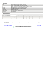
<Print head>
Type
Single head with 4 removable ink tanks (each color)
Print head
Black: 320 nozzles (600dpi), 30pl (pigment-based black)
Color: 256 nozzles x 5 (1,200dpi), 2pl / 5pl (cyan, magenta), 5pl (yellow)
Ink color
Pigment-based black, Dye-based cyan, magenta, yellow
Ink tank
PGI-5BK (pigment-based), CLI-8C/M/Y (dye-based)
Weight (Net)
Print head, approx. 56g
Supply method
As a service part (not including ink tanks)
Part number
QY6-0064-000
<Supported ink tanks>
Pigment-based ink
Model name and destination
Dye-based ink
PGI-5BK
BCI-9BK
CLI-8C
CLI-8M
CLI-8Y
BCI-7eC
BCI-7eM
BCI-7eY
PIXMA iX5000 / iX4000
Other than Japan
O
X
O
O
O
X
X
X
PIXUS iX5000
Japan
X
O
X
X
X
O
O
O
O: Usable
X: Not usable
Note: The ink tanks for the Japanese models are not compatible with those for the non-Japanese models. Be sure to use the appropriate ink
tanks in servicing.
To the table of contents
To the top
<Part 3: 3. PIXMA iX5000 / iX4000 Specifications> 3-9