1
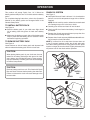
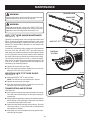
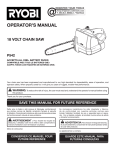
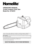
OPERATOR’S MANUAL 18 VOLT cHAIN sAW P540 P540A P540B ACCEPTS ALL one+ BATTERY PACKS batterIES and chargers sold Separately Your chain saw has been engineered and manufactured to our high standard for dependability, ease of operation, and operator safety. When properly cared for, it will give you years of rugged, trouble-free performance. WARNING: To reduce the risk of injury, the user must read and understand the operator's manual before using this product. Thank you for your purchase. SAVE THIS MANUAL FOR FUTURE REFERENCE TABLE OF CONTENTS Introduction........................................................................................................................................................................2 General Safety Rules...................................................................................................................................................... 3-5 Specific Safety Rules..........................................................................................................................................................6 Symbols.......................................................................................................................................................................... 7-8 Features..............................................................................................................................................................................9 Assembly..........................................................................................................................................................................10 Operation.................................................................................................................................................................... 10-18 Maintenance............................................................................................................................................................... 19-25 Troubleshooting................................................................................................................................................................26 Warranty...........................................................................................................................................................................27 Parts Ordering / Service..................................................................................................................................... Back Page INTRODUCTION This product has many features for making its use more pleasant and enjoyable. Safety, performance, and dependability have been given top priority in the design of this product making it easy to maintain and operate. general SAFETY RULES n Keep handles dry, clean, and free of oil and grease. WARNING: n Do not operate a chain saw that is damaged, improperly adjusted, or not completely and securely assembled. Chain should stop turning when the trigger is released. If the chain turns after the trigger has been released, have the unit serviced by your nearest Ryobi service dealer. Do not attempt to operate this unit until you have read thoroughly and understand completely all instructions, safety information, etc. contained in this manual. Failure to comply can result in accidents involving fire, electric shock, or serious personal injury. n Check for damaged parts. Any part or guard that has been damaged should be carefully checked to determine that it will operate properly and perform its intended function. Check for alignment of moving parts, binding of moving parts, breakage of parts, mounting, and any other conditions that may affect its operation. A guard or other part that is damaged should be properly repaired or replaced by an authorized service dealer unless otherwise indicated elsewhere in this manual. READ ALL INSTRUCTIONS Basic Safety Precautions n Do not operate a chain saw with one hand! Use a firm grip with thumbs and fingers encircling the chain saw handles. Serious injury to the operator, helpers, bystanders, or any combination of these persons may result from one-handed operation. A chain saw is intended for two-handed use. n Always be aware of what you are doing when using the chain saw. Use common sense. Do not operate the chain saw when you are tired, ill, or under the influence of alcohol, drugs, or medication. n Stay alert and pay attention to what you are doing. Use common sense when using this unit. n Keep all parts of your body away from the saw chain when the unit is running. n Always carry the chain saw by the front handle with the unit stopped and the guide bar and saw chain positioned to the rear. When transporting your chain saw, use the appropriate guide bar scabbard. n Never let anyone use your chain saw who has not received adequate instructions in its proper use. This applies to rentals as well as privately owned saws. n Before you start the unit, make sure the saw chain is not contacting any object. n Stop the chain saw before setting it down. Do not leave the unit running unattended. n To avoid accidental starting, never carry the unit with your finger on the trigger. n Maintain the unit with care. Keep the cutting edge sharp and clean for best performance and to reduce the risk of injury. Follow instructions for lubricating and changing accessories. Inspect the battery charger cord periodically, and if damaged, have it replaced or repaired by an authorized service dealer. n All chain saw service, other than the items listed in the operation and maintenance sections, should be performed by your nearest Ryobi service dealer. n Do not use in the rain, snow or wet conditions. n Always maintain a proper stance. Do not overreach. n Do not adapt your powerhead to a bow guide or use it to power any attachments or devices not listed for the saw. n Do not cut vines and/or small underbrush. SAFETY APPAREL n Wear snug fitting clothing. Always wear heavy, long pants, overalls, jeans or chaps made of cut resistant material or ones that contain cut resistant inserts. Wear non-slip safety footwear. Wear non-slip heavy duty gloves to improve your grip and to protect your hands. Do not wear jewelry, short pants, sandals, or go barefoot. Do not wear loose fitting clothing, which could be drawn into the motor or catch the chain or underbrush. Secure hair so it is above shoulder level. n Wear eye protection which is marked to comply with ANSI Z87.1 as well as hearing and head protection when operating this equipment. general SAFETY RULES Kickback ROTATIONAL KICKBACK See Figures 1 - 2. n WARNING: Kickback may occur when the moving chain contacts an object at the upper portion of the tip of the guide bar or when the wood closes in and pinches the saw chain in the cut. Contact at the upper portion of the tip of the guide bar can cause the chain to dig into the object and stop the chain for an instant. The result is a lightning fast, reverse reaction which kicks the guide bar up and back toward the operator. If the saw chain is pinched along the top of the guide bar, the guide bar can be driven rapidly back toward the operator. Either of these reactions can cause loss of saw control which can result in serious injury. Do not rely exclusively upon the safety devices built into the saw. As a chain saw user, you should take several steps to keep your cutting jobs free from accident or injury. n The following precautions should be followed to minimize kickback: 1. Always grip the saw firmly with both hands. Hold the saw firmly with both hands when the unit is running. Place your right hand on the rear handle and your left hand on the front handle with your thumbs and fingers encircling the chain saw handles. A firm grip together with a stiff left arm will help you maintain control of the saw if kickback occurs. 2. Make sure that the area in which you are cutting is free from obstructions. Do not let the nose of the guide bar contact a log, branch, fence, or any other obstruction that could be hit while you are operating the saw. 3. Always cut with the unit running at full speed. Fully squeeze the throttle trigger and maintain a steady cutting speed. 4. Use replacement parts such as low kickback chain, SAFE-T-TIP® anti-kickback nose guards, chain brakes and special guide bars that reduce the risks associated with rotational kickback. Use only the replacement guide bars and low kickback chains specified by the manufacturer for the saw. n With a basic understanding of kickback, you can reduce or eliminate the element of surprise. Sudden surprise contributes to accidents. n Keep proper footing and balance at all times. n Do not cut above shoulder height or overreach when cutting. n Keep the SAFE-T-TIP® anti-kickback nose guard properly mounted on the guide bar to prevent rotational kickback. n Follow the sharpening and maintenance instructions for the saw chain. n Push and Pull - This reaction force is always opposite to the direction the chain is moving where wood contact is made. Thus, the operator must be ready to control the PULL when cutting on the bottom edge of the bar, and PUSH when cutting along the top edge. See Figure 3. bar shown without safe-t-tip® nose guard for illustration purposes only. Fig. 1 KICKBACK DANGER ZONE Fig. 2 PULL PUSH Fig. 3 general SAFETY RULES Understanding Your Chain Saw Safety Devices In The Cutting/Work Area n Do not operate a chain saw in a tree, on a ladder, or scaffold; this is extremely dangerous. See Figure 4. SAFE-T-TIP® Anti-Kickback Nose Guard n Keep ALL children, bystanders, visitors, and animals out of the work area while starting or cutting with the chain saw. The SAFE-T-TIP® prevents kickback from happening, because it covers the tip of the bar where kickback is generated. Never attempt any kind of cutting where the SAFE-TTIP® would have to be removed from the bar tip. NOTE: The size of the work area depends on the job being performed as well as the size tree or work piece involved. For example, felling a tree requires a larger work area than making bucking cuts. Low Kickback Saw Chain The rakers (depth gauges) ahead of each cutter can minimize the force of a kickback reaction by preventing the cutters from digging in too deeply at the kickback zone. Only use replacement chain that is equivalent to original chain or has been certified as low kickback chain per ANSI B175.1. Low kickback saw chain is chain that has met the kickback performance requirements of ANSI B175.1 - 1991 (American National Standard for Power Tools - Gasoline-Powered Chain Saws-Safety Requirements) when tested on the representative sample of chain saws below 3.8 c.i.d. specified in ANSI B175.1 - 1991. As saw chains are sharpened during their useful life, they lose some of the low kickback qualities and extra caution should be used. n Never start cutting until you have a clear work area, secure footing, and a planned retreat path from the falling tree. Cluttered area invite injuries. n Do not expose the chain saw to rain. n Do not use the chain saw in damp or wet locations. n Do not use the chain saw near flammable liquids, gases, or in any type of explosive atmosphere. n Use extreme caution when cutting small size brush and saplings, because slender material may catch the saw chain and be whipped toward you or pull you off balance. n When cutting a limb that is under tension, be alert for spring back so that you will not be struck when the tension in the wood fibers is released. Guide Bars n Do not force the chain saw. The job can be performed better and safer at the rate for which it was intended. Generally, guide bars with small radius tips have somewhat lower kickback potentials. When making a replacement, be sure to order one of the Ryobi bars listed for the saw in this operator's manual. The proper size SAFE-T-TIP® nose guard comes installed on the bar. Use only guide bars that have a provision for mounting the SAFE-T-TIP®. n Always use the right product for your application. The chain saw should be used for cutting wood only. Never use the chain saw to cut plastic, masonry or non-wood building materials. n Do not use the chain saw for purposes not intended. n Store idle chain saw when not in use. Chain saw should be stored in a dry and high or locked area out of the reach of children. When storing chain saw, remove battery and place the scabbard on the bar and chain or store the chain saw in a carry case. SAFE-T-TIP® n Remove the battery pack from the chain saw before cleaning, servicing, storing, removing material from the unit, changing accessories such as the bar and chain, or when not in use. Fig. 4 SPECIFIC SAFETY RULES BATTERY SAFETY explosion. Properly dispose of a dropped or damaged battery immediately. n Batteries can explode in the presence of a source of ignition, such as a pilot light. To reduce the risk of serious personal injury, never use any cordless product in the presence of open flame. An exploded battery pack can propel debris and chemicals. If exposed, flush with water immediately. n Do not charge unit in a damp or wet location. Following this rule will reduce the risk of electric shock. n For best results, your battery unit should be charged in a location where the temperature is more than 50°F but less than 100°F. Do not store outside or in vehicles. n Under extreme usage or temperature conditions, battery pack leakage may occur. If liquid comes in contact with your skin, wash immediately with soap and water, then neutralize with lemon juice or vinegar. If liquid gets into your eyes, flush them with clean water for at least 10 minutes, then seek immediate medical attention. n Do not dispose of batteries in a fire. The cell may explode. Batteries should be recycled, consult your local waste authority for information regarding available recycling and/or disposal options. n When battery pack is not in use, keep it away from other metal objects like: paper clips, coins, keys, nails, screws, or other small metal objects that can make a connection from one terminal to another. Shorting the battery pack terminals together may cause sparks, burns, or a fire. n Battery operated units do not have to be plugged into an electrical outlet; therefore, they are always in operating condition. Be aware of possible hazards even when unit is not operating. n Remove the battery pack from the chain saw before cleaning, servicing, storing, removing material from the unit, changing accessories such as the bar and chain, or when not in use. n A battery pack must be recharged only with the specified charger for the battery pack. A charger that may be suitable for one type of battery pack may create a risk of fire when used with another battery pack. Use battery pack only with charger listed. MODEL P540 P540A P540B BATTERY PACK (P104 Li-ion) 130429001, 130429002 130155001 (P100 Ni-Cd) 130255004, 130224028 BATTERY PACK CHARGER (P113) 140501001 140501005 CHARGER (P110) 1423701, 140237021, (P100 Ni-Cd) 130255004, 130224028 140237023 n To reduce the risk of explosion and possible injury, Do not place battery units or their batteries near fire or heat. n Do not open or mutilate the battery pack. Released electrolyte is corrosive and may cause damage to the eyes or skin. It may be toxic if swallowed. Do not crush, drop or damage battery pack. Do not use a battery pack or charger that has been dropped or received a sharp blow. A damaged battery is subject to SYMBOLS Some of the following symbols may be used on this product. Please study them and learn their meaning. Proper interpretation of these symbols will allow you to operate the product better and safer. SYMBOL NAME DESIGNATION/EXPLANATION V Volts Voltage A Amperes Current Hz Hertz Frequency (cycles per second) W Watt Power Minutes Time Alternating Current Type of current Direct Current Type or a characteristic of current No Load Speed Rotational speed, at no load Class II Construction Double-insulated construction Per Minute Revolutions, strokes, surface speed, orbits etc., per minute Wet Conditions Alert Do not expose to rain or use in damp locations. Read The Operator’s Manual To reduce the risk of injury, user must read and understand operator’s manual before using this product. Wear Eye, Hearing, and Head Protection Wear eye protection which is marked to comply with ANSI Z87.1 as well as hearing and head protection when operating this equipment. Safety Alert Precautions that involve your safety. SAFE-T-TIP Nose Guard The SAFE-T-TIP nose guard on the guide bar helps prevent kickback. Operate With Two Hands Hold and operate the saw properly with both hands. One Handed Do not operate the saw using only one hand. Kickback Danger! Beware of kickback. Bar Nose Contact Avoid bar nose contact. Wear Gloves Wear non-slip, heavy-duty protective gloves when handling the chain saw. Wear Safety Footwear Wear non-slip safety footwear when using this equipment. Keep Bystanders Away Keep all bystanders and animals at least 50 ft. away. min no .../min SYMBOLS The following signal words and meanings are intended to explain the levels of risk associated with this product. SYMBOL SIGNAL MEANING DANGER: Indicates an imminently hazardous situation, which, if not avoided, will result in death or serious injury. WARNING: Indicates a potentially hazardous situation, which, if not avoided, could result in death or serious injury. CAUTION: Indicates a potentially hazardous situation, which, if not avoided, may result in minor or moderate injury. CAUTION: (Without Safety Alert Symbol) Indicates a situation that may result in property damage. SERVICE WARNING: Servicing requires extreme care and knowledge and should be performed only by a qualified service technician. For service we suggest you return the product to your nearest AUTHORIZED SERVICE CENTER for repair. When servicing, use only identical replacement parts. To avoid serious personal injury, do not attempt to use this product until you read thoroughly and understand completely the operator’s manual. If you do not understand the warnings and instructions in the operator’s manual, do not use this product. Call Ryobi customer service for assistance. WARNING: The operation of any power tool can result in foreign objects being thrown into your eyes, which can result in severe eye damage. Before beginning power tool operation, always wear safety goggles, safety glasses with side shields, or a full face shield when needed. We recommend Wide Vision Safety Mask for use over eyeglasses or standard safety glasses with side shields. Always use eye protection which is marked to comply with ANSI Z87.1. SAVE THESE INSTRUCTIONS FEATURES PRODUCT SPECIFICATIONS Motor.......................................................................................................................................................................18 Volt DC Bar Length....................................................................................................................................................................... 10 in. Replacement Bar Part Number.......................................................................................................671256002 or 671834007 Replacement Chain Part Number.......................................................................................................6958301 or 690583002 NOTE: This saw was designed for occasional light duty use and has some limitations as to what it can cut. SCABBARD chain oil tank cap REAR HANDLE BAR SAFE-T-TIP® CHAIN HAND GUARD BATTERY PACK (NOT INCLUDED) FRONT HANDLE trigger release button BATTERY PACK (NOT INCLUDED) HEX KEY HEX KEY storage area trigger Fig. 5 ASSEMBLY UNPACKING WARNING: This product has been shipped completely assembled. If any parts are damaged or missing do not operate this product until the parts are replaced. Failure to heed this warning could result in serious personal injury. n Carefully remove the product and any accessories from the box. Make sure that all items listed in the packing list are included. n Inspect the product carefully to make sure no breakage or damage occurred during shipping. n Do not discard the packing material until you have carefully inspected and satisfactorily operated the product. n If any parts are damaged or missing, please call 1-800-860-5040 for assistance. WARNING: Do not attempt to modify this product or create accessories not recommended for use with this product. Any such alteration or modification is misuse and could result in a hazardous condition leading to possible serious personal injury. PACKING LIST Chain Saw with Scabbard Wrench WARNING: Bar and Chain Lubricant Operator’s Manual To prevent accidental starting that could cause serious personal injury, always remove the battery pack from the product when assembling parts. OPERATION WARNING: WARNING: Do not use any attachments or accessories not recommended by the manufacturer of this product. The use of attachments or accessories not recommended can result in serious personal injury. Do not allow familiarity with this product to make you careless. Remember that a careless fraction of a second is sufficient to inflict serious injury. WARNING: APPLICATIONS You may use this product for the following purposes: Always wear safety goggles or safety glasses with side shields when operating power tools. Failure to do so could result in objects being thrown into your eyes resulting in possible serious injury. Limbing and pruning branches from trees Felling small trees up to 5 in. diameter Bucking the fallen tree into shorter lengths 10 OPERATION Chain Oil System This product will accept Ryobi One+ 18 V lithium-ion battery packs and Ryobi One+ 18 V nickel-cadmium battery packs. See Figure 7. Use Ryobi Bar and Chain Lubricant. It is formulated to perform over a wide temperature range with no dilution required. NOTE: Do not use dirty, used or otherwise contaminated oils. Damage may occur to the bar or chain. Carefully pour the bar and chain oil into the tank. Check and fill the oil tank when battery is recharged, or as needed. Depress the oil tank cap several times to pump the oil to the chain before starting the saw. Depress the oil tank cap every 20-30 seconds while cutting to keep the chain lubricated. NOTE: It is normal for oil to seep from the saw when not in use. To prevent seepage, empty the oil tank after each use. When storing the unit for a long period of time (three months or longer) be sure the chain is lightly lubricated; this will prevent rust on the chain and bar sprocket. For complete charging instructions, refer to the Operator’s Manual for the battery packs and chargers listed in the General Safety Rules. TO INSTALL BATTERY PACK See Figure 6. Place the battery pack in your chain saw. Align raised rib on battery pack with groove in chain saw’s battery port. Make sure the latches on each side of the battery pack snap in place and that battery pack is secured in chain saw before beginning operation. TO REMOVE BATTERY PACK See Figure 6. Locate latches on side of battery pack and depress both sides to release the battery pack from the chain saw. CAUTION: When placing battery pack in your chain saw, be sure raised rib on battery pack aligns with groove in chain saw's battery port and latches snap in place properly. Improper assembly of battery pack can cause damage to internal components. CAUTION: battery port Remove battery pack from unit. Fill oil tank with Ryobi Bar and Chain Lubricant before starting the chain saw. Failure to lubricate the chain will cause damage to the bar and chain. battery pack latches Fig. 6 Fig. 7 11 OPERATION STARTING AND STOPPING THE CHAIN SAW See Figure 8. WARNING: Keep body to the left of the chain line. Never straddle the saw or chain, or lean over past the chain line. Starting the chain saw: Place the chain saw on a flat bare surface and make sure no objects or obstructions are in immediate vicinity which could come in contact with the bar and chain. Press and hold the trigger release button. This makes the trigger operational. Press and hold the trigger, release the trigger release button and continue to squeeze the trigger for continued operation. trigger release button trigger Stopping the chain saw: Release the trigger to stop the chain saw. Upon release of the trigger, the trigger release button will be automatically reset to the lock position. This cordless chain saw is not designed for cutting trees larger than 5 in. in diameter. This cordless chain saw is designed for limbing and pruning type cutting, as well as cutting trees up to 5 in. in diameter only. Do not attempt to make any cut that would require removal of the SAFE-T-TIP®. trigger release button Preparation for Cutting Proper Grip on Handles See Figures 9 - 11. Refer to Important Safety Instructions earlier in this manual for appropriate safety equipment. Wear non-slip gloves for maximum grip and protection. Hold the saw firmly with both hands. Always keep your left hand on the front handle and your right hand on the rear handle so that your body is to the left of the chain line. trigger 12 Fig. 8 OPERATION WARNING: Never use a left-handed (cross-handed) grip, or any stance which would place your body or arm across the chain line. Maintain a proper grip on the saw whenever the unit is running. The fingers should encircle the handle and the thumb is wrapped under the handlebar. This grip is least likely to be broken (by a kickback or other sudden reaction of the saw). Any grip in which the thumb and fingers are on the same side of the handle, is dangerous because a slight kick of the saw can cause loss of control. Fig. 9 WARNING: Do not operate the throttle trigger with your left hand and hold the front handle with your right hand. Never allow any part of your body to be in the chain line while operating a saw. Fig. 10 Chain Line Fig. 11 13 OPERATION Proper Cutting Stance See Figure 12. Weight should be balanced with both feet on solid ground. CHAIN LINE Keep left arm with elbow locked in a "straight arm" position to withstand any kickback force. STRAIGHT ARM POSITION Your body should always be to the left of the chain line. Thumb should be on underside of handlebar. Basic Cutting Procedure Practice cutting a few small logs using the following technique to get the "feel" of using the saw before you begin a major sawing operation. Fig. 12 Take the proper stance in front of the wood with the saw off. Always cut with both feet on solid ground to prevent being pulled off balance. Do not cut above chest height, as a saw held higher is difficult to control against kickback forces. Do not fell trees near electrical wires or buildings. Leave this operation for professionals. Cut only when visibility and light are adequate for you to see clearly. Squeeze the trigger and let the chain accelerate to full speed before entering the cut. Begin cutting with the saw against the log. Keep the unit running the entire time you are cutting, maintain a steady speed. Allow the chain to cut for you; exert only light downward pressure. If you force the cut, damage to the bar, chain, or unit can result. Release the trigger as soon as the cut is completed, allowing the chain to stop. If you run the saw without a cutting load, unnecessary wear can occur to the chain, bar, and unit. Tree Felling Unusual Hazardous Tree Felling Conditions Do not fell trees during periods of high wind or heavy precipitation. Wait to do your cutting until the hazard has ended. Do not put pressure on the saw at the end of the cut. Work Area Precautions WARNING: Cut only wood or materials made from wood, no sheet metal, no plastics, no masonry, no non-wood building materials. Do not cut down trees having an extreme lean or large trees that have rotten limbs, loose bark, or hollow trunks. Have these trees pushed or dragged down with heavy equipment, then cut them up. Never allow children to operate the saw. Allow no person to use this chain saw who has not read this Operator's Manual or received adequate instructions for the safe and proper use of this chain saw. WARNING: When felling a tree, keep everyone - helpers, bystanders, children, and animals - a safe distance from the cutting area. During felling operations, the safe distance should be a least twice the height of the largest trees in the felling area. During bucking operations, keep a minimum distance of 15 feet (4.5 m) between workers.Trees should not be felled in a manner that would endanger any person, strike any utility line or cause any property damage. If the tree does make contact with any utility line, the utility company should be notified immediately. Do not cut trees near electrical wires or buildings. WARNING: Check the tree for damaged or dead branches that could fall and hit you during felling. 14 OPERATION planned line of fall WARNING: Periodically glance at the top of the tree during the backcut to assure the tree is going to fall in the desired direction. WARNING: If the tree starts to fall in the wrong direction, or if the saw gets caught or hung up during the fall, leave the saw and save yourself! Felling a tree - When bucking and felling operations are being performed by two or more persons, at the same time, the felling operation should be separated from the bucking operation by a distance of at least twice the height of the tree being felled. Trees should not be felled in a manner that would endanger any person, strike any utility line or cause any property damage. If the tree does make contact with any utility line, the utility company should be notified immediately. Before any cuts are started, pick your escape route (or routes in case the intended route is blocked); clear the immediate area around the tree and make sure there are no obstructions in your planned path of retreat. Clear path of safe retreat approximately 135° from planned line of fall. The retreat path should extend back and diagonally to the rear of the expected line of fall. See Figure 13. Before felling is started, consider the force and direction of the wind, the lean and balance of the tree, and the location of large limbs. These things influence the direction in which the tree will fall. Do not try to fell a tree along a line different from its natural line of fall. The chain saw operator should keep on the uphill side of the terrain as the tree is likely to roll or slide downhill after it is felled. Remove dirt, stones, loose bark, nails, staples, and wire from the tree where felling cuts are to be made. Notched Undercut. Cut a notch about 1/3 the diameter of the tree, perpendicular to the direction of fall. Make the cuts of the notch so they intersect at a right angle to the line of fall. This notch should be cleaned out to leave a straight line. To keep the weight of the wood off the saw, always make the lower cut of the notch before the upper cut. See Figure 14. 90° safe retreat zone Planned path of safe retreat 135° from planned line of fall planned line of fall safe retreat zone 135° 45° 90° 45° 135° safe retreat zone Fig. 13 HINGE 2 in. or 1/10 DIA NOTCH APPROX. 1/3 DIAMETER OF TRUNK BACK CUT 2 in. 15 Fig. 14 OPERATION Felling Backcut. The backcut is always made level and horizontal, and at a minimum of 2 in. above the horizontal cut of the notch. See Figures 14 - 15. Sometimes it is impossible to avoid pinching (with just standard cutting techniques) or difficult to predict which way a log will settle when cut. To avoid pinching while cutting, rotate or move the log so that the pinch is eliminated. Never cut through to the notch. Always leave a band of wood between the notch and backcut (approximately 2 in. or 1/10 the diameter of the tree). This is called "hinge" or “hingewood.” It controls the fall of the tree and prevents slipping or twisting or shoot-back of the tree off the stump. See Figures 14 - 15. On large diameter trees, stop the back cut before it is deep enough for the tree to either fall or settle back on the stump. Then insert soft wooden or plastic wedges into the cut so they do not touch the chain. The wedges can be driven in, little by little, to help jack the tree over. See Figure 16. NOTCH BACK CUT NOTE: When bucking or felling with a wedge, it may be necessary to remove the SAFE-T-TIP® anti-kickback device to allow the bar to be drawn through the cut. After the cut is complete, the tip should be reinstalled immediately. HINGE Fig. 15 As tree starts to fall, stop the chain saw and put it down immediately. Retreat along the cleared path, but watch the action in case something falls your way. Be alert for overhead limbs or branches that may fall and watch your footing. WARNING: Never cut through to the notch when making a backcut. The hinge controls the fall of the tree, this is the section of wood between the notch and backcut. wedge Fig. 16 kickback Bucking See Figures 17 - 20. Bucking is the term used for cutting a fallen tree to the desired log length. Always make sure your footing is secure and your weight is distributed evenly on both feet. Cut only one log at a time. Support small logs on a saw horse or another log while bucking. Keep a clear cutting area. Make sure that no objects can contact the guide bar nose and chain during cutting, this can cause kickback. To avoid the danger, keep the SAFET-TIP® anti-kickback device attached while cutting. Refer to Precautions Against Kickback earlier in this manual. When bucking on a slope, always stand on the uphill side of the log. To maintain complete control of the chain saw when cutting through the log, release the cutting pressure near the end of the cut without relaxing your grip on the chain saw handles. Do not let the chain contact the ground. After completing the cut, wait for the saw chain to stop before you move the chain saw. Always stop the motor before moving from tree to tree. Fig. 17 Fig. 18 16 OPERATION BUCKING Logs Under Stress Log Supported at One End: See Figures 19 - 20. When the log is supported along its entire length, it should be cut from the top or overbucking. When the log is supported on one end, cut 1/3 the diameter from the underside or underbucking. Then make the finishing cut by overbucking to meet the first cut. As the log is being cut, it will tend to bend. The saw can become pinched or hung in the log if you make the first cut deeper than 1/3 of the diameter of the log. Give special attention to logs under stress to prevent the bar and chain from pinching. When bucking on a slope, always stand on the uphill side of the log as shown in figure 18. When “cutting through,” to maintain complete control of the chain saw, release the cutting pressure near the end of the cut without relaxing your grip on the chain saw handles. Do not let the chain contact the ground. After completing the cut, wait for the saw chain to stop before you move the chain saw. Always stop the motor before moving from tree to tree. LOAD finishing cut 1st CUT 1/3 Dia Log Supported at Both Ends: LOAD 1st CUT 1/3 Dia Types of Cutting Used See Figure 20. Overbucking Begin on the top side of the log with the bottom of the saw against the log; exert light pressure downward. Note that the saw will tend to pull away from you. FINISHING CUT Underbucking Begin on the under side of the log with the top of the saw against the log; exert light pressure upward. During underbucking, the saw will tend to push back at you. Be prepared for this reaction and hold the saw firmly to maintain control. Fig. 19 Overbucking WARNING: Never climb into a tree to limb or prune. Do not stand on ladders, platforms, a log, or in any position which can cause you to lose your balance or control of the saw. Underbucking Fig. 20 17 OPERATION Limbing See Figure 21. Limbing is removing branches from a fallen tree. Work slowly, keeping both hands on the chain saw with a firm grip. Always make sure your footing is secure and your weight is distributed evenly on both feet. Leave the larger support limbs under the tree to keep the tree off the ground while cutting. Limbs should be cut one at a time. Remove the cut limbs from the work area often to help keep the work area clean and safe. Branches under tension should be cut from the bottom up to avoid binding the chain saw. 2 1 3 4 CUT LIMBS ONE AT A TIME AND leave support limbs under tree until log is cut Fig. 21 Keep the tree between you and the chain saw while limbing. Cut from the side of the tree opposite the branch you are cutting. LOAD Second cut Pruning See Figure 22. Pruning is trimming limbs from a live tree. Work slowly, keeping both hands on the chain saw with a firm grip. Always make sure your footing is secure and your weight is distributed evenly on both feet. Do not cut from a ladder, this is extremely dangerous. Leave this operation for professionals. Do not cut above chest height as a saw held higher is difficult to control against kickback. When pruning trees it is important not to make the finishing cut next to the main limb or trunk until you have cut off the limb further out to reduce the weight. This prevents stripping the bark from the main member. Underbuck the branch 1/3 through for your first cut. Your second cut should overbuck to drop the branch off. Now make your finishing cut smoothly and neatly against the main member so the bark will grow back to seal the wound. First cut 1/3 diameter Finishing cut Fig. 22 SPRINGPOLE Fig. 23 WARNING: WARNING: Springpoles are dangerous and could strike the operator, causing the operator to lose control of the chain saw. This could result in severe or fatal injury to the operator. If the limbs to be pruned are above chest height, hire a professional to perform the pruning. Springpoles See Figure 23. A springpole is any log, branch, rooted stump, or sapling which is bent under tension by other wood so that it springs back if the wood holding it is cut or removed. On a fallen tree, a rooted stump has a high potential of springing back to the upright position during the bucking cut to separate the log from the stump. Watch out for springpoles, they are dangerous. 18 MAINTENANCE GENERAL MAINTENANCE WARNING: Avoid using solvents when cleaning plastic parts. Most plastics are susceptible to damage from various types of commercial solvents and may be damaged by their use. Use clean cloths to remove dirt, dust, oil, grease, etc. When servicing, use only identical replacement parts. Use of any other parts may create a hazard or cause product damage. WARNING: WARNING: Do not at any time let brake fluids, gasoline, petroleumbased products, penetrating oils, etc., come in contact with plastic parts. Chemicals can damage, weaken or destroy plastic which may result in serious personal injury. Always wear safety goggles or safety glasses with side shields during power product operation or when blowing dust. If operation is dusty, also wear a dust mask. WARNING: Only the parts shown on the parts list are intended to be repaired or replaced by the customer. All other parts should be replaced at an Authorized Service Center. To avoid serious personal injury, always remove the battery pack from the product when cleaning or performing any maintenance. BATTERY PACK REMOVAL AND PREPARATION FOR RECYCLING BATTERIES This product will accept 18 V lithium-ion batteries or 18 V nickel-cadmium batteries. Length of service from each charging will depend on the type of work you are doing. The batteries for this product have been designed to provide maximum trouble-free life. However, like all batteries, they will eventually wear out. Do not disassemble battery pack and attempt to replace the batteries. Handling of these batteries, especially when wearing rings and jewelry, could result in a serious burn. To obtain the longest possible battery life, we suggest the following: To preserve natural resources, please re c yc l e or di spose of ba tte ri e s properly. Li - Ion This product uses nickel-cadmium and lithium-ion batteries. Local, state or federal laws may prohibit disposal of batteries in ordinary trash. Consult your local waste authority for information regarding available recycling and/or disposal options. For lithium-ion batteries: WARNING: Remove the battery pack from the charger once it is fully charged and ready for use. Upon removal, cover the battery pack’s terminals with heavy-duty adhesive tape. Do not attempt to destroy or disassemble battery pack or remove any of its components. Lithium-ion and nickel-cadmium batteries must be recycled or disposed of properly. Also, never touch both terminals with metal objects and/or body parts as short circuit may result. Keep away from children. Failure to comply with these warnings could result in fire and/or serious injury. For battery pack storage longer than 30 days: Store the battery pack where the temperature is below 80°F and away from moisture. Store battery packs in a 30%-50% charged condition. Every six months of storage, charge the pack as normal. For nickel-cadmium batteries: Remove the battery pack from the charger once it is fully charged and ready for use. For battery pack storage longer than 30 days: Store the battery pack where the temperature is below 80°F. Store battery packs in a “discharged” condition. 19 MAINTENANCE REPLACing Bar and Chain See Figures 24 - 28. adjusting pin sprocket warning: Remove the battery pack from the chain saw and make sure the chain has stopped before you do any work on the saw. Failure to do so may result in accidental starting and possible serious injury bar WARNING: washer The safety instructions in this section are to protect the user from serious personal injury. CAUTION: chain Always wear gloves when handling the bar and chain; these components are sharp and may contain burrs. chain tension pin hole chain cover chain cover screw Fig. 24 WARNING: Never touch or adjust the chain while the motor is running. The saw chain is very sharp; always wear protective gloves when performing maintenance to the chain to avoid possible serious lacerations. Remove the battery pack before you do any work on the chain saw. Remove the hex key from the storage area and use it to remove the chain cover screw, washer and chain cover from the chain saw. Remove the bar and chain from the mounting surface. Remove the old chain from the bar. Lay out the new saw chain in a loop and straighten any kinks. The cutters should face in the direction of chain rotation. If they face the opposite direction, turn the loop over. Place the chain drive links into the bar groove. Position the chain so there is a loop at the back of the bar. Hold the chain in position on the bar and place the loop around the sprocket of the chain saw. Fit the bar flush against the mounting surface so that the bar stud is in the long slot of the bar. NOTE: When placing the bar on the bar stud, assure that the adjusting pin is in the chain tension pin hole. chain drive links bar groove Fig. 25 Chain tensioning screw Recommended Bar and Chain Combinations Bar Part Number - 10 in. 671256002 or 671834007 Fig. 26 Chain Part Number 6958301 or 690583002 20 MAINTENANCE Replace the chain cover, washer and chain cover screw. Tighten the chain cover screw finger tight only. The bar must be free to move for tension adjustment. Remove all the slack from the chain by turning the chain tensioning screw clockwise until the chain seats snugly against the bar with the drive links in the bar groove. Lift the tip of the guide bar up to check for sag. Release the tip of the guide bar and turn the chain tensioning screw 1/2 turn clockwise. Repeat this process until sag does not exist. Hold the tip of the guide bar up and tighten the bar mounting screw securely. Chain is correctly tensioned when there is no sag on the underside of the guide bar, the chain is snug, but it can be turned by hand without binding. NOTE: If chain is too tight, it will not rotate. Loosen the chain cover screw slightly and turn tension adjuster 1/4 turn counterclockwise. Lift the tip of the guide bar up and retighten chain cover screw securely. Assure that the chain will rotate without binding. Place the hex key back into the storage area. Lift the tip of the guide bar up to check for sag Fig. 27 Chain Tension See Figures 29 - 30. Stop the engine before setting the chain tension. Make sure the guide bar screw is loosened to finger tight, turn the chain tensioner clockwise to tension the chain. Refer to Replacing Bar and Chain earlier in this manual for additional information. A cold chain is correctly tensioned when there is no slack on the underside of the guide bar, the chain is snug, but it can be turned by hand without binding. Chain must be re-tensioned whenever the flats on the drive links hang out of the bar groove. During normal saw operation, the temperature of the chain will increase. The drive links of a correctly tensioned warm chain will hang approximately .050 in. out of the bar groove. NOTE: New chain tends to stretch, check chain tension frequently and tension as required. hex key Fig. 28 Approx. .050 in. Fig. 29 flats CAUTION: Fig. 30 Chain tensioned while warm, may be too tight upon cooling. Check the “cold tension” before next use. 21 MAINTENANCE Chain Maintenance See Figures 31 - 32. Cutting Corner CAUTION: Top Plate Remove the battery pack and make sure the chain has stopped before you do any work on the saw. Side Plate Depth Gauge Rivet Hole Use only low-kickback chain on this saw. This fast-cutting chain will provide kickback reduction when properly maintained. For smooth and fast cutting, chain needs to be maintained properly. The chain requires sharpening when the wood chips are small and powdery, the chain must be forced through the wood during cutting, or the chain cuts to one side. During maintenance of your chain, consider the following: Improper filing angle of the side plate can increase the risk of a severe kickback. Raker (depth gauge) clearance. Too low increases the potential for kickback. Not low enough decreases cutting ability. If cutter teeth have hit hard objects such as nails and stones, or have been abraded by mud or sand on the wood, have service dealer sharpen chain. NOTE: Inspect the drive sprocket for wear or damage when replacing the chain. If signs of wear or damage are present in the areas indicated, have the drive sprocket replaced by a Ryobi Service dealer. Heel Toe Gullet Fig. 31 check for wear or damage Fig. 32 How to Sharpen the Cutters See Figures 33 - 34. Be careful to file all cutters to the specified angles and to the same length, as fast cutting can be obtained only when all cutters are uniform. Wear gloves for protection. Properly tension the chain prior to sharpening. Refer to Chain Tension Section earlier in this manual. Do all of your filing at the mid-point of the bar. Use a 5/32 in. diameter round file and holder. Keep the file level with the top plate of the tooth. Do not let the file dip or rock. Using light but firm pressure, stroke towards the front corner of the tooth. Lift file away from the steel on each return stroke. Put a few firm strokes on every tooth. File all left hand cutters in one direction. Then move to the other side and file the right hand cutters in the opposite direction. Occasionally remove filings from the file with a wire brush. Fig. 33 LEFT HAND CUTTERS RIGHT HAND CUTTERS 22 Fig. 34 MAINTENANCE WARNING: correcT TOP PLATE FILING ANGLE Improper chain sharpening increases the potential of kickback. 30° INcorrecT TOP PLATE FILING ANGLE LESS THAN 30° MORE THAN 30° WARNING: Failure to replace or repair damaged chain can cause serious injury. Fig. 35 WARNING: correct SIDE PLATE FILING ANGLE The saw chain is very sharp, always wear protective gloves when performing maintenance to the chain. INcorrect SIDE PLATE FILING ANGLE HOOK Top Plate Filing Angle See Figure 35. BACKWARD SLOPE 80° CORRECT 30° - File holders are marked with guide marks to align file properly to produce correct top plate angle. LESS THAN 30° - For Cross Cutting. MORE THAN 30° - Feathered Edge Dulls Quickly. Fig. 36 Side Plate Angle See Figure 36. raker clearance .025 in. CORRECT - 80o Produced automatically if correct diameter file is used in file holder. HOOK - “Grabs” and dulls quickly. Increases potential of KICKBACK. Results from using a file with diameter too small, or file held too low. BACKWARD SLOPE - Needs too much feed pressure, causes excessive wear to bar and chain. Fig. 37 Results from using a file with diameter too large, or file held too high. Depth Gauge Clearance See Figure 37 - 39. The depth gauge should be maintained at a clearance of .025 in. Use a depth gauge tool for checking the depth gauge clearances. Every time the chain is filed, check the depth gauge clearance. 23 MAINTENANCE Replace the SAFE-T-TIP® on the bar nose. NOTE: The locking tab fits in the recessed hole in the bar. Tighten the screw with your finger. From the finger-tight position, tighten the screw an additional 3/4 of a turn using a wrench. Use a Flat File and a Depth Gauge Jointer to lower all gauges uniformly. Depth gauge jointers are available in .020 in. to .035 in. Use a .025 in. depth gauge jointer. After lowering each depth gauge, restore original shape by rounding the front. Be careful not to damage adjoining drive links with the edge of the file. Depth gauges must be adjusted with the flat file in the same direction the adjoining cutter was filed with the round file. Use care not to contact cutter face with flat file when adjusting depth gauges. DEPTH GAUGE JOINTER GUIDE BAR MAINTENANCE See Figure 40. When the guide bar shows signs of wear, reverse it on the saw to distribute the wear for maximum bar life. The bar should be cleaned every day of use and checked for wear and damage. Feathering or burring of the bar rails is a normal process of bar wear. Such faults should be smoothed with a file as soon as they occur. A bar with any of the following faults should be replaced. Wear inside the bar rails which permits the chain to lay over sideways. Bent guide bar. Cracked or broken rails. Spread rails. In addition, guide bars with a sprocket at their tip must be lubricated weekly with a grease syringe to extend the guide bar life. Using a grease syringe, lubricate weekly in the lubricating hole. Turn the guide bar and check that the lubrication holes and chain groove are free from impurities. FLAT FILE Fig. 38 RESTORE ORIGINAL SHAPE BY rounding the front Fig. 39 Reversing the guide bar See Figures 40 - 42. Remove the SAFE-T-TIP® mounting screw. Remove the SAFE-T-TIP® from the bar. Remove the chain from the bar and turn the bar over. NOTE: Bottom of bar should not be on top. Replace the chain on the bar. Refer to Assembling the Bar and Chain earlier in this manual for specific information. LUBRICATING HOLE Fig. 40 24 MAINTENANCE mounting screw WARNING: Remove the battery pack and make sure the chain has stopped before you do any work on the saw. locking rivet WARNING: Although the guide bar comes with a SAFE-T-TIP® antikickback device already installed, you need to check the tightness of the mounting screw before each use. SAFE-T-TIP® Nose Guard Maintenance See Figures 41 - 42. Tighten the mounting screw of the nose guard as instructed below. These are specially hardened screws. If the screw cannot be installed tightly, replace both the screw and the SAFE-T-TIP® before further operation. Do not replace with an ordinary screw. In addition to preventing chain contact with solid objects at the nose of the bar, the SAFE-T-TIP® also helps keep the chain away from abrasive surfaces such as the ground. Keep it on the right hand side of the bar, where it will be between the chain and the ground during flush with ground cutting. The mounting screw requires a 5/16 in. wrench (or adjustable wrench) to achieve the recommended tightness of 35 to 45 in. lb. (4-5 Nm). A tightness within this range can be achieved by the following method. Tighten the screw with your finger. From the finger-tight position, tighten the screw an additional 3/4 of a turn using a wrench. SAFE-T-TIP® Fig. 41 tighten 3/4 of a turn Fig. 42 Mounting SAFE-T-TIP® Nose Guard See Figures 41 - 42. Mount the SAFE-T-TIP® on the bar nose. NOTE: The tab fits in the recessed hole in the bar. Tighten the screw with your finger. From the finger-tight position, tighten the screw an additional 3/4 of a turn using a wrench. TRANSPORTING AND STORING See Figure 43. Do not store or transport the chain saw when it is running. The chain saw should always be idle before storing or transporting. Always place the guide bar scabbard on the bar and chain before storing or transporting the chain saw. Use caution to avoid the sharp teeth of the chain. Clean the chain saw thoroughly before storing. Store the chain saw indoors, in a dry place that is locked and/or inaccessible to children. Keep away from corrosive agents such as garden chemicals and de-icing salts. Fig. 43 25 TROUBLESHOOTING ProblemCause Solution Bar and chain running hot and smoking. 1. Check chain tension for over tight condition 2. Chain oil tank empty. 1. Tension chain. Refer to Chain Tension earlier in this manual. 2. Check oil tank. Motor runs, but chain is not rotating. 1. Chain tension too tight. 2. Check guide bar and chain assembly. 3. Check guide bar and chain for damage. 1. Retension chain, Refer to Chain Tension earlier in this manual. 2. Refer to Assembling the Bar and Chain earlier in this manual. 3. Inspect guide bar and chain for damage. CALL US FIRST CALL 50 1-800-860-40 m ols.co yobito www.r For any questions about operating or maintaining your product, call the Ryobi® Help Line! Your product has been fully tested prior to shipment to ensure your complete satisfaction. 26 WARRANTY LIMITED WARRANTY STATEMENT A.Tune-ups – Spark Plugs, Carburetor, Carburetor Adjustments, Ignition, Filters B. Wear items – Bump Knobs, Outer Spools, Cutting Lines, Inner Reels, Starter Pulleys, Starter Ropes, Drive Belts, Tines, Felt Washers, Hitch Pins, Mulching Blades, Blower Fans, Blower and Vacuum Tubes, Vacuum Bag and Straps, Guide Bars, Saw Chains Techtronic Industries North America, Inc., reserves the right to change or improve the design of any Ryobi® brand outdoor product without assuming any obligation to modify any product previously manufactured. Techtronic Industries North America, Inc., warrants to the original retail purchaser that this Ryobi® brand outdoor product is free from defect in material and workmanship and agrees to repair or replace, at Techtronic Industries North America, Inc.’s, discretion, any defective product free of charge within these time periods from the date of purchase. Two years if the product is used for personal, family or household use; 90 days, if used for any other purpose, such as commercial or rental. This warranty extends to the original retail purchaser only and commences on the date of the original retail purchase. Any part of this product found in the reasonable judgment of Techtronic Industries North America, Inc. to be defective in material or workmanship will be repaired or replaced without charge for parts and labor by an authorized service center for RYOBI® brand outdoor products (Authorized Ryobi Service Center). The product, including any defective part, must be returned to an authorized Ryobi service center within the warranty period. The expense of delivering the product to the service center for warranty work and the expense of returning it back to the owner after repair or replacement will be paid by the owner. Techtronic Industries North America, Inc.’s, responsibility in respect to claims is limited to making the required repairs or replacements and no claim of breach of warranty shall be cause for cancellation or rescission of the contract of sale of any Ryobi® brand outdoor product. Proof of purchase will be required by the dealer to substantiate any warranty claim. All warranty work must be performed by an authorized service dealer. This warranty is limited to ninety (90) days from the date of original retail purchase for any Ryobi® brand outdoor product that is used for rental or commercial purposes, or any other income-producing purpose. This warranty does not cover any product that has been subject to misuse, neglect, negligence, or accident, or that has been operated in any way contrary to the operating instructions as specified in this operator’s manual. This warranty does not apply to any damage to the product that is the result of improper maintenance or to any product that has been altered or modified. The warranty does not extend to repairs made necessary by normal wear or by the use of parts or accessories which are either incompatible with the ryobi® brand outdoor product or adversely affect its operation, performance, or durability. In addition, this warranty does not cover: ALL IMPLIED WARRANTIES ARE LIMITED IN DURATION TO THE STATED WARRANTY PERIOD. ACCORDINGLY, ANY SUCH IMPLIED WARRANTIES INCLUDING MERCHANTABILITY, FITNESS FOR A PARTICULAR PURPOSE, OR OTHERWISE, ARE DISCLAIMED IN THEIR ENTIRETY AFTER THE EXPIRATION OF THE APPROPRIATE TWO-YEAR, ONE-YEAR, OR NINETYDAY WARRANTY PERIOD. Techtronic Industries North America, Inc.’s, OBLIGATION UNDER THIS WARRANTY IS STRICTLY AND EXCLUSIVELY LIMITED TO THE REPAIR OR REPLACEMENT OF DEFECTIVE PARTS AND Techtronic Industries North America, Inc., DOES NOT ASSUME OR AUTHORIZE ANYONE TO ASSUME FOR THEM ANY OTHER OBLIGATION. SOME STATES DO NOT ALLOW LIMITATIONS ON HOW LONG AN IMPLIED WARRANTY LASTS, SO THE ABOVE LIMITATION MAY NOT APPLY TO YOU. Techtronic Industries North America, Inc., ASSUMES NO RESPONSIBILITY FOR INCIDENTAL, CONSEQUENTIAL, OR OTHER DAMAGES INCLUDING, BUT NOT LIMITED TO, EXPENSE OF RETURNING THE PRODUCT TO AN AUTHORIZED ryobi SERVICE center AND EXPENSE OF DELIVERING IT BACK TO THE OWNER, MECHANIC’S TRAVEL TIME, TELEPHONE OR TELEGRAM CHARGES, RENTAL OF A LIKE PRODUCT DURING THE TIME WARRANTY SERVICE IS BEING PERFORMED, TRAVEL, LOSS OR DAMAGE TO PERSONAL PROPERTY, LOSS OF REVENUE, LOSS OF USE OF THE PRODUCT, LOSS OF TIME, OR INCONVENIENCE. SOME STATES DO NOT ALLOW THE EXCLUSION OR LIMITATION OF INCIDENTAL OR CONSEQUENTIAL DAMAGES, SO THE ABOVE LIMITATION OR EXCLUSION MAY NOT APPLY TO YOU. This warranty gives you specific legal rights, and you may also have other rights which vary from state to state. This warranty applies to all Ryobi® brand outdoor products manufactured by or for Techtronic Industries North America, Inc., and sold in the United States and Canada. To locate your nearest Authorized Ryobi Service Center, dial 1-800-860-4050. 27 OPERATOR’S MANUAL 18 VOLT cHAIN sAW P540 p540a P540B • Parts and Service Prior to requesting service or purchasing replacement parts, please obtain your model and serial number from the product data plate. • MODEL NUMBER • SERIAL NUMBER P540/P540A/P540B • How to obtain Replacement Parts: Replacement parts can be purchased online at www.ryobitools.com or by calling 1-800-860-4050. Replacement parts can also be obtained at one of our Authorized Service Centers. • How to locate an Authorized Service Center: Authorized Service Centers can be located online at www.ryobitools.com or by calling 1-800-860-4050. • How to obtain Customer or Technical Support: To obtain Customer or Technical Support please contact us at 1-800-860-4050. Ryobi® is a registered trademark of Ryobi Limited used under license. TECHTRONIC INDUSTRIES NORTH AMERICA, INC. 1428 Pearman Dairy Road, Anderson, SC 29625 Phone 1-800-860-4050 www.ryobitools.com 983000-538 4-15-08 (REV:06)