1
engineering
mannesmann
Rexroth
AC Main Spindle Drives with Controlled
Asynchronous Motors and Frameless
Spindle Motors
Applications Manual
DOK-DIAX01-MAIN+2AD+1M-ANW1-EN-P
252103
Indramat
• DOK-DIAX01-MAIN+2AD+1M-ANW1-EN-E1,44 • 07.97
2
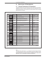
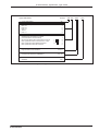
Overview of Sections
Section
About this Documentation
____________________________________________________________________
Table of Contents
____________________________________________________________________
Commissioning
1
__________________________________________________________________
Operating the Controllers
2
____________________________________________________________________
Controller Functions
3
____________________________________________________________________
Diagnostics and Fault Clearance
4
____________________________________________________________________
Summary of Parameters
5
____________________________________________________________________
Overview of Interfaces and Associated Functions
6
____________________________________________________________________
Index
7
____________________________________________________________________
Abbreviations and Agreements, Type Codes
8
____________________________________________________________________
Supplementary Documentation
9
____________________________________________________________________
• DOK-DIAX01-MAIN+2AD+1M-ANW1-EN-E1,44 • 07.97
3
• DOK-DIAX01-MAIN+2AD+1M-ANW1-EN-E1,44 • 07.97
4
About this documentation
Titel
Type of documentation:
Documenttype
Internal file reference
Reference
This documentation
is used:
AC Main Spindle Drives with Controlled Asynchronous Motors
and Frameless Spindle Motors
Applications Manual
DOK-DIAX01-MAIN+2AD+1M-ANW1-EN-E1,44
• 209-0041-4109-01
This electronic document is based on the hardcopy document with document
desig.: 209-0041-4109-01 EN/06.93
This documentation
• Assists in the commission of AC main spindle drives used in module
systems with KDA/TDA or complete systems with RAC.
• Explains how to operate the controllers.
• Clarifies the technical background specific to the applications and the
technical conversion of the main spindle drive functions. Complex functions
are graphically illustrated where necessary.
• Explains the diagnostics of the main spindle drives and can be used as a
reference when clearing faults.
This documentation:
• Offers safety guidelines on how to handle Indramat drives.
• Summarizes drive parameters and functional interfaces.
• Can be used as a reference when setting the parameters of the drive at the
time of delivery and to agree with the machine (parameter protocols).
Change procedures
Copyright
Designation of documentation
up to present edition
Release- Coments
date
209-0041-4109-01 EN/06.93
Jun/93
Release
DOK-DIAX01-MAIN+2AD+1M-ANW1-EN-E1,44
Jul./97
First E-Dok
© INDRAMAT GmbH, 1992
Copying of this document, and giving it to others and the use or communication
of the contents thereof, are forbidden without express authority. Offenders are
liable to the payment of damages.
All rights are reserved in the event of the grant of a patent or the registration
of a utility model or design. (DIN 34-1)
The electronic documentation (E-doc) may be copied as often as needed if
such are to be used by the consumer for the purpose intended.
Validity
Publisher
All rights reserved with respect to the content of this documentation and the
availability of the products.
INDRAMAT GmbH • Bgm.-Dr.-Nebel-Straße 2 • D-97816 Lohr
Telefon 0 93 52 / 40-0 • Tx 689421 • Fax 0 93 52 / 40-48 85
Dept ENA (MR, FS)
• DOK-DIAX01-MAIN+2AD+1M-ANW1-EN-E1,44 • 07.97
5
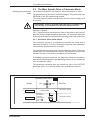
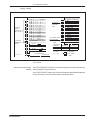
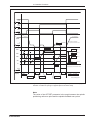
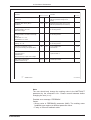
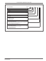
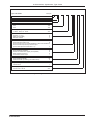
About this document
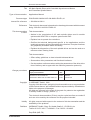
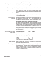
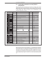
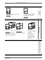
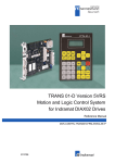
Documentation summary "AC main spindle drives with controlled ...
AC main spindle drives
with controlled
asynchronous motor
Main Spindle Drive Applications
(commissioning, operating, diagnosing)
Project Planning
(construction, mounting, installing the machine)
Select
(details, ordering)
2AD
AC main spindle drives with controlled
2AD asynchronous motor
Selection data
- summary of the AC main drive system
- power ratings
- technical functions of the AC main spindle drive
- selecton protocols and order lists
- product availability
Asynchronmotor
Asynchronmotor
200
Asynchronmotor
180
Asynchronmotor
160
Asynchronmotor
RAC4
RAC3
RAC2
Electrical
connectons for
main spindle
drives
TDA1
Controller
KDA3
Controller
Project Planning
- control cabinet plans
- AS programming module
- delivery, storage, transportation
- mounting and installation guidelines
Asynchronous motor
Electrical connections
Project Planning
- general guidelines on the
electrical connections
- circuit diagrams of feedback
and NC connections for
all main spindle drives
- circuit diagrams of the power
connections for all main
spindle drives
- connector kits, ready-made
cables
You have this document ....
101
132
2AD100
Asynchronous motor
Project Planning
- machine construction plans
- delivery, storage, transportation
- mounting and installation guidelines
ACmain spindle drives
with controlled
asynchronous motor or
frameless spindle motor
AC main spindle drives with controlled
asynchronous motors or frameless spindle
motors
Applications description
- AC main spindle drive commissioning
- operating the controller
- the functions of the controller
- diagnostics and fault clearance
- summary of parameters and interfaces
Figure 1: Documentation summary
• DOK-DIAX01-MAIN+2AD+1M-ANW1-EN-E1,44 • 07.97
6
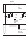
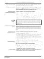
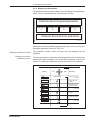
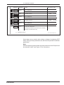
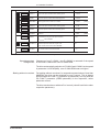
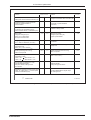
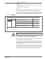
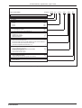
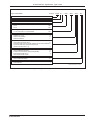
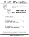
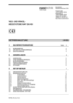
About this document
AC main spindle drive
with 1MB controlled
frameless spindle motor
AC main spindle
drives with
changeover
gearboxes
1MB
AC main spindle drives with 2AD
controlled asynchronous motor and
changeover 2K planetary gearboxes
Selection data
- summary of the AC main drive system
- power ratings
- order guidelines
Bausatzspindelmotor
Bausatzspindelmotor
1MB 375
1MB 310
1MB 240
1MB 200
1MB 160
Bausatzspindelmotor
Bausatzspindelmotor
Framless spindle
motor
1MB
1MB - Stator
- Rotor
Frameless spindle motor
Mounting guidelines
- delivery, handling, transport
- mounting
- cooling guidelines
Supplementary documentation
- high-resolution main
spindle position encocer
- incremental encoder output IGS
- high-resolution encoder
branching HGV
Main Spindle Drive Applications
(commissioning, operating, diagnosing)
Project Planning
- machine construction plans
- integrating into the cooling system
- electrical and coolant connections
- delivery
HGV
High-resolution
main spindle IGS
position encoder
Project Planning
(construction, mounting, installing the machine)
AC spindle drive with 1MB controlled frameless
spindle motor
Selection data
- summary of the AC main drive system
- power ratings
- technical functions of the AC main spindle drive
- selection protocols and order lists
- product availability
Select
(details, ordering)
... asynchronous motor or frameless spindle motor"
• DOK-DIAX01-MAIN+2AD+1M-ANW1-EN-E1,44 • 07.97
7
• DOK-DIAX01-MAIN+2AD+1M-ANW1-EN-E1,44 • 07.97
8
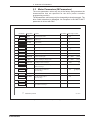
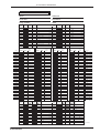
Contents
Contents
1.
Commissioning INDRAMAT AC Main Spindle Drives
13
1.1
Summary of Main Spindle Drive Systems ......................................13
1.2
1.2.1
1.2.2
1.2.3
Safety Guidelines ...........................................................................16
Notes on Protecting Personnel ......................................................16
Guidelines on Protecting Equipment ..............................................17
Guidelines on Protecting the Machine ........................................... 17
1.3
The Equipment Required ...............................................................18
1.4
1.4.1
1.4.2
1.4.3
1.4.4
1.4.5
Main Spindle Drives with KDA or TDA ........................................... 19
Mains Supply Requirements ..........................................................19
Checks with the Equipment Switched Off ......................................19
Checks with the Signal Conditioning Powered Up .........................20
Checks after the Power Infeed has been Connected .................... 21
Initial Start-Up ................................................................................22
1.5
1.5.1
1.5.2
1.5.3
Main Spindle Drives with RAC Controllers ....................................23
Mains Requirements ......................................................................23
Checks with the Equipment Switched-Off ......................................23
Checks with Mains Supply Connected/Power Circuits ......................
Disconnected .................................................................................24
1.5.4 Connecting the Power Infeed .........................................................26
1.5.5 Initial Start-Up ................................................................................26
2.
Operating the Controllers
27
2.1
The Control Panel ..........................................................................27
2.2 Main Spindle Drive in Operating Mode ..........................................28
2.2.1 Displaying the Internal State Variables of the Drive ....................... 29
2.2.2 Outputting the Drive Internal State Variables for Analogue
Output N .........................................................................................29
2.3
2.3.1
2.3.2
2.3.3
2.3.4
2.3.5
2.3.6
The Main Spindle Drive in Parameter Mode .................................. 31
Parameter Value Quick-Check .......................................................31
Reading the Parameters ................................................................ 32
Changing the Parameters .............................................................. 33
Displaying the Software Version ....................................................35
Duplicating the Parameters ............................................................35
Loading Operating Parameters via Serial Interface ....................... 36
3.
Controller Functions
3.1
Drive "Ready" State .......................................................................37
37
3.2 Speed Command Value .................................................................38
3.2.1 Analogue Speed Command Value (option) ....................................38
3.2.2 Digital Speed Command Value (option) ......................................... 41
3.3
Main Spindle Speed Signals ..........................................................44
• DOK-DIAX01-MAIN+2AD+1M-ANW1-EN-E1,44 • 07.97
9
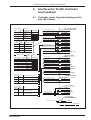
Contents
3.4
Speed Command Value Ramps .....................................................45
3.5
Command Value Smoothing ..........................................................48
3.6
3.6.1
3.6.2
3.6.3
Spindle Positioning.........................................................................50
Basic Data for Spindle Positioning ................................................. 52
Spindle Positioning via Motor Feedback ........................................ 56
Spindle Positioning via Motor Feedback with
Spindle Reference Switch .............................................................. 57
3.6.4 Spindle Positioning via Spindle Feedback ..................................... 60
3.7
Speed Controller Functions ...........................................................62
3.8
C-Axis Function ..............................................................................64
3.9
Power and Torque Limits................................................................ 67
3.10 Drive Utilitzation Output .................................................................69
3.10.1 Analogue output for drive utilization (analogue output M) ............. 69
3.10.2Signal output with adjustable threshold for drive utilization
(LOAD LIMIT) .................................................................................73
3.11 Temperature Pre-Warning .............................................................. 74
3.12 Maximum Spindle Speed ...............................................................75
3.13 Spindle Monitor ..............................................................................76
3.14 Switchable Parameter Records .....................................................77
3.15 Gear Change ..................................................................................79
3.15.1Automatic Gear Change via the Controller ....................................79
3.15.2Gear Change via an External Controller ........................................ 83
3.16 Two-Motor Changeover.................................................................. 85
3.17 Master-Slave Operation .................................................................88
3.18 EMERGENCY-STOP circuit (RAC) ................................................92
3.19 Performance during mains failure (RAC) ....................................... 93
3.20 Performance during mains failure and E-stop (KDA, TDA) ........... 95
3.21 Starting lockout in KDA/TDA ..........................................................96
3.22 Serial Interface (option) – in preparation ....................................... 97
3.23. SERCOS interface (option) - in preparation .................................. 97
3.24 Incremental Encoder Output (option) – see Section 9 .................. 97
4.
Diagnostics and Fault Clearance
4.1
Operating Status Diagnostics ........................................................98
4.2
Fault Diagnostics ..........................................................................100
5.
Overview of Parameters
• DOK-DIAX01-MAIN+2AD+1M-ANW1-EN-E1,44 • 07.97
98
106
10
Contents
5.1
General Parameters (A Parameters) ........................................... 106
5.2
Switchable parameter records (P,Q,R,S parameters) .................. 109
5.3
Motor Parameters (M Parameters) .............................................. 111
5.4
Parameter Protocol and Additions List ......................................... 113
6.
Interfaces for the NC Controller and Feedback
6.1
Controller Inputs, Signal and Analogue Outputs, Bb Contact ...... 116
6.2
Analogue Speed Command Value •10V (option) ......................... 118
6.3
Digital Speed Command Value (option) ....................................... 119
6.4
SERCOS Interface (option) ..........................................................120
6.5
Digital Position Command Value (option) ....................................121
6.6
Incremental Encoder Output (option) ........................................... 122
6.7
Serial Interface (option) ................................................................ 123
6.8
Motor Feedback Connection ........................................................124
6.9
Additional Encoder Input (option) ................................................125
7.
Index
126
8.
Abbreviations, Agreements, Type Codes
136
9.
Supplementary documentation
144
• DOK-DIAX01-MAIN+2AD+1M-ANW1-EN-E1,44 • 07.97
116
11
• DOK-DIAX01-MAIN+2AD+1M-ANW1-EN-E1,44 • 07.97
12
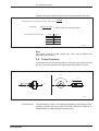
1. Commissioning INDRAMAT AC Main Spindle Drives
1.
Commissioning INDRAMAT AC Main
Spindle Drives
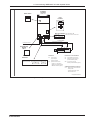
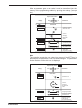
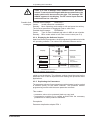
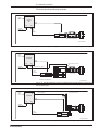
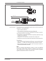
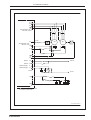
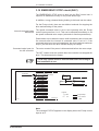
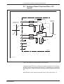
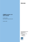
1.1
Summary of Main Spindle Drive Systems
AS programming
module
three-phase mains
supply module
main spindle
drive module
KDA or TDA
additional axis modules
bus
for control
voltage
Bb - contact ( X11 )
interfaces to the NC
X2:
signal outputs
X4
X2
heatsink blower
(KDA only)
analogue outputs
X4:
speed command value
- analogue ± 10V (option)
X5a
motor feedback
- digital 16 bit parallel (option)
- SERCOS interface (option)
interfaces to the feedback
X5
X3
motor connection
user interface
control inputs
X3:
motor feedback connection
X5:
additional encoder input for
spindle feedback (option)
X5a: synchronous input for
master spindle feedback (option)
motor blower
additional interface (option):
(underneath the control unit)
X6
mains
X6:
- digital position command value
16 bit parallel
- incremental encoder output
- interface RS 232 C
Hauptspindel-KDA/TDA
Figure 2: Main spindle drives with KDA or TDA (modular drive system)
• DOK-DIAX01-MAIN+2AD+1M-ANW1-EN-E1,44 • 07.97
13
1. Commissioning INDRAMAT AC Main Spindle Drives
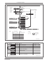
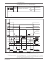
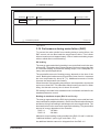
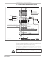
Complete
controller
RAC 2.2
Main switch
0
User
terminal
I
AC-MAINSPINDLE DRIVE
RAC
Plug-in terminals: X15: ON,OFF,CS, Bb
X16
X15
X16: thermo-sensor of the motor
motor feedback
motor blower connection
three-phase mains
motor connection
Programming
module
AS 5./
Interfaces
X13
X4
X5a
Interfaces
Interfaces to the feedback
X2:
control inputs
X3:
motor feedback connection
signal outputs
X5:
additional encoder intput for
analogue outputs
X5
X4:
X2
X3
speed command value
- analogue ± 10V (option)
spindle feedback (option)
X5a: synchronous input for
master spindle feedback (option)
- digital 16 bit parallel (option)
- SERCOS interface (option)
Additional interfaces (option):
X13: - digital position command value
16 bit parallel
- incremental encoder output
- interface RS 232 C
Hauptspindel-RAC2.2
Figure 3: Main spindle drive with RAC 2.2 controller
• DOK-DIAX01-MAIN+2AD+1M-ANW1-EN-E1,44 • 07.97
14
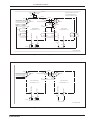
1. Commissioning INDRAMAT AC Main Spindle Drives
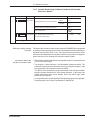
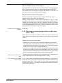
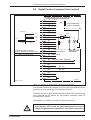
Complete
controller
RAC 3.1
three-phase mains
motor connection
control voltage 220V ~
Plug-in terminal:
X16
X15: ON,OFF,CS, Bb
X16: thermo-sensor of the motor
User
terminal
INDRAMAT
AC-MAINSPINDLE DRIVE
RAC
motor feedback
Programming
module
AS 6./
motor blower
three-phase mains
Interfaces
X13
X15
X4
X5a
Interfaces
Interfaces to the feedback
X2:
control inputs
X3:
motor feedback connection
signal outputs
X5:
additional encoder input for
analogue outputs
X5
X4:
X2
X3
speed command value
- analogue ± 10V (option)
spindle feedback (option)
X5a: synchronous input for
master spindle feedback (option)
- digital 16 bit parallel (option)
- SERCOS interface (option)
Additional interfaces (option):
X13: - digital position command value
16 bit parallel
- incremental encoder output
- interface RS 232 C
Hauptspindel-RAC3.1
Figure 4: Main spindle drive with RAC 3.1 complete controller
For RAC 4.1:
The same arrangement applies here as with an RAC 2.2 (Figure 3). The
motor blower does not receive its power from the RAC 4.1, however. It
must be directly connected to the three-phase mains!
The name of the programming module is AS 8./..
• DOK-DIAX01-MAIN+2AD+1M-ANW1-EN-E1,44 • 07.97
15
1. Commissioning INDRAMAT AC Main Spindle Drives
1.2
Safety Guidelines
1.2.1 Notes on Protecting Personnel
The following problems can occur when operating a drive or a drive
package for the first time:
• wiring fault
• fault in NC program
• for operational reasons, monitors are not working
These can cause increased risk of accidents and can lead to
• personal injuries,
• damage to drives and
• machines.
The drive may only be operated as prescribed in the relevant
documentation!
Danger from moving axes
There is danger from moving axes due to
• unintentional starting due to malfunctions and faults and
• operation in the speed or position control circuit.
Precautionary measures for personnel:
• Personnel must not remain in the area of the machine in which
movements can take place.
• The drives must be stopped and secured against unintentional starting
when personnel are working in the hazardous area.
Precautionary measures against unintentional starting:
• Disconnect the power contactor (EMERGENCY STOP).
• Switch the master switch off during prolonged breaks in operation.
Danger from contact with
electrical parts
Dangerous voltages on equipment terminals:
• mains voltage L1, L2 and L3
• DC bus voltage L+,L• motor voltage A1, A2 and A3
Open master switches and secure against reconnection prior
to working on electrical equipment. The drives must be securely
locked because voltage appears on the motor cables when the
motors rotate!
• DOK-DIAX01-MAIN+2AD+1M-ANW1-EN-E1,44 • 07.97
16
1. Commissioning INDRAMAT AC Main Spindle Drives
1.2.2 Guidelines on Protecting Equipment
Risk of damage due to
incorrect connection
• Allow approximately five minutes for DC bus to discharge. Check that
voltage is below 50V before commencing work. If in doubt, use shortcircuit!
• The transparent cover or front panel must be screwed on to prevent
accidental contact during operation.
• Current-operated e.l.c.b systems cannot be used with INDRAMAT
equipment. In the case of indirect contact, the mains contactor should
be replaced by other means, e.g., overcurrent protective devices.
Risk of damage due to
separate source or high
voltage
Indramat electronic drive components are fitted with comprehensive
protection circuits and are protected against overload as far as is
technically feasible.
• Connect to the inputs of the unit only those voltages which conform to
the specified data.
• Outputs must not be connected to separate voltage sources.
• Mains, DC bus and motor cables must not be connected to or brought
into contact with low-voltage ±15V and +24V rails. They must be
adequately insulated from each other.
Indramat drive components are subjected during routine testing to highvoltage tests which conform to VDE 0160 standards.
If a high-voltage or separate-source voltage withstand test is carried out
on the electrical equipment of the machine, then all the connections of the
unit must be disconnected or withdrawn to avoid damaging the electronic
components in the units (permissible as per VDE 0113).
Risk of damage due to
electrostatic charge
Electrostatic charges damage electronic components. The human body,
which can come into contact with components and printed circuit boards,
must be discharged by earthing:
• the human body by touching a conductive, earthed object
• the soldering iron when soldering
• parts and tools must be placed on a conductive substrate
Components at risk, such as programming modules, should only be
stored or dispatched in conductive packaging.
1.2.3 Guidelines on Protecting the Machine
If, during commissioning, the position control loop of the NC controller is
run and the drive is run in the speed control loop, then there exists the risk
of damage to the machine because of the limited travel of linear axes.
To prevent machine damage:
• the drive enable signal and speed command value should only be
applied by skilled personnel and
• the emergency stop facility should be provided by limit switches or
EMERGENCY-STOP (E-stop) buttons.
• DOK-DIAX01-MAIN+2AD+1M-ANW1-EN-E1,44 • 07.97
17
1. Commissioning INDRAMAT AC Main Spindle Drives
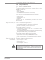
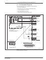
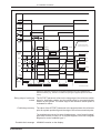
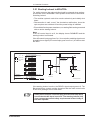
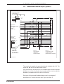
1.3
The Equipment Required
The following equipment is needed for commissioning:
• DC and AC multimeter
• command value box (analogue command value)
• 37-pin subminiature connector
• 9-pin subminiature connector
• 10-pin plug terminal block (RAC only)
command value box
X4
S1
1
2
(E1)
(E2)
4
5
6
(E3)
(E4)
7
8
9
0V
-15V
+15V
V
10k
R1
R2
+/- 10V
1k
S2
X2
1
2
3
R1: 10-speed potentiometer for Ucomm
R2: protective resistor
S1: 3-pin switch
S2: switch for RF enabling signal
V: DC voltameter for display
0V ext
0V int
AS (KDA/TDA only)
18
19
+24V int
+24V ext
23
24
25
E-STOP( RAC only)
RF
RUN
controlller
9-pin Cannon plug
1
soldering side
5
37-pin Cannon plug
soldering side
1
6
19
9
soldering contact
20
soldering contact
37
Sollwertbox
Figure 5: Circuit for operating the drive with the above equipment (command value
box and subminiature connectors)
• DOK-DIAX01-MAIN+2AD+1M-ANW1-EN-E1,44 • 07.97
18
1. Commissioning INDRAMAT AC Main Spindle Drives
1.4
Main Spindle Drives with KDA or TDA
1.4.1 Mains Supply Requirements
Each time prior to switching on, check that the mains supply meets the
requirements of the supply module being used (see supply module
documentation).
1.4.2 Checks with the Equipment Switched Off
Checking the drive
components
The installed drive components must be designed for the existing input
voltages. The input voltages shown on the rating plate should be
checked against the type code (see respective drive and supply module
documentation).
The details on the AS programming module must match the ratings of the
installed drive components, otherwise there is a risk of damage.
Condition of wiring
Check the wiring for short-circuits, breaks, incorrect connections,
conductor cross sections and identify these against the Indramat
connection diagram.
• Earthing arrangements:
The earthing arrangements should be made exactly as per the
respective connection diagrams. These should also include the relevant protective measures for the machine. Each motor must be
earthed at its associated drive module.
Drive modules should be separately earthed at the power supply
module. The earthing point of the supply module is the central
reference earth point for all drive components. This should be connected
to the mains earth. The above earth connections provide an operational
earth with a protective function.
When installing the modules in the control cabinet, ensure that the
housing makes a good electrical connection with the control cabinet.
Otherwise faults could occur.
• Twisting the load conductors:
The motor connections from the main drive module should be either
twisted or a four-core cable (3 x phase, 1 x earth) should be used.
• Connections to auxiliary modules:
The power connections to the additional capacitance module or to
further additional storage capacitors should be twisted and kept as
short as possible.
• Power connections to the main drive modules:
Normally, the units are alongside each other and the connection is
made via two busbars. If this is not possible, then the power connection
must be made with two twisted 16 mm2 conductors not more than one
meter in length.
Cross sections of power
cables
The cross sections of conductors must be such that the permissible
current densities stipulated by the relevant specifications (VDE 0100 and
VDE 0113) are not exceeded at the maximum ambient temperatures and
the corresponding continuous motor and transformer currents.
• DOK-DIAX01-MAIN+2AD+1M-ANW1-EN-E1,44 • 07.97
19
1. Commissioning INDRAMAT AC Main Spindle Drives
Checking the terminals and
connectors
Check that the conductors are securely attached to the terminals,
otherwise there exists the risk of damage. The subminiature connectors
must be screwed up!
Bus connecting cable
The control voltage and monitor connections are made via a bus cable
the black core of which must be underneath.
End connector for bus
connecting cable
Ensure that the line monitor end connector supplies with the power
supply module is fitted to the drive module farthest from the power supply
module.
Shielding
The shielding of the command value cable and motor feedback cable, the
spindle transmitter cable and temperature sensor leads must be connected
at the main drive module.
Power transformer
connection
Where a power transformer is required for the supply module, make sure
that the primary and secondary sides of the transformer are not
interchanged. Excessively high supply voltage can damage the drive.
1.4.3 Checks with the Signal Conditioning Powered Up
First, with the drive package switched off, disconnect the speed command
from the controller (X4) and remove the connections to the control inputs
and signal outputs (X2). Connect the command value box to interface X4
and connect the control inputs X2 as shown in Figure 4 of section 1.3.
Control voltage must be available at the power supply module before the
following checks can be carried out. The voltage for the signal conditioning
circuits is then available in the drive modules. The mains contactor K1
must be switched off.
Check LED and LCD display
status signals
At the supply module:
Color:
Status:
• bleeder overload
red
off
• power on
green
off
At the main drive module KDA or TDA:
• FAULT
red
off
• READY
green
off
• NO POWER must appear in the LCD display.
Blower operation
Check the blower and the electrical connections in the main drive
modules and the main drive motors.
Power stage on/off
sequence
The correct switching sequence is obtained when the "ready" contacts
of the supply and main drive modules are installed as per the Indramat
connection diagrams. The power can only then be applied when the Bb1
contact in the supply module is closed. Any series resistors are shortcircuited only if the Bb contact of the main drive modules closes or +24V
is present at the READY output.
• DOK-DIAX01-MAIN+2AD+1M-ANW1-EN-E1,44 • 07.97
20
1. Commissioning INDRAMAT AC Main Spindle Drives
DC bus dynamic braking
To ensure that the main drive can be braked when the mains is
disconnected, fit no DC bus short-circuit resistor.
Checking motor feedback
Set mode switch to right. Pressing the "up" arrow key brings the motor
speed N into the display (see Section 2, "Operating the Controllers").
Positive speed must be indicated on the display when the motor shaft is
rotated clockwise by hand (motor shaft viewed from front).
Checking the speed
command value (analogue)
Press the "up" arrow until speed command C appears.
• Positive voltage at connector X4/1 with respect to X4/2 shows a
positive command in the display.
• For C-axis operation, apply positive command to connector X4/5 with
respect to X4/6. Activate command value input via EXT POS input and
parameter PQ-FUNCT (P/Q/R/S 16). A positive command again
appears in the display (see Section 3.8, "C-axis Operation").
The null of the command value input is set at the factory with
the inputs short-circuited and may be adjusted for command
value input X4/1 and X4/2 with potentiometer P1 above connector
X4, and command value input X4/5 and X4/6 with potentiometer
P2 below X4.
Checking the spindle speed
detector
Checking the motor
temperature detector
Condition: separate spindle feedback must be connected to the optional
interface on the second encoder input (X5). Press the "up" arrow key until
spindle speed S appears in the display. Positive speed must appear in
the display when the incremental encoder shaft is rotated clockwise by
hand.
Press the "up" arrow key until motor temperature T appears.
• Display with cold motor: „T<40°C“.
• A flashing display means that the motor temperature sensors are
incorrectly connected or the motor temperature is less than 0°C.
• The drive switches off after ten minutes if the motor temperature
sensors are faulty. „NO TEMP“ appears. „TEMP WARN“ goes to 0
thirty seconds before this.
1.4.4 Checks after the Power Infeed has been Connected
Check status signals
Set controller enabling switch on command value box to OFF and set
speed command value to 0 volts.
Now, connect the power supply to the drive package.
• The green "power on" LED on the supply module must light up.
• "NO RF" (no controller enabling signal) must appear in the KDA
module display.
• The green LED „READY“ on the KDA must light up.
DC bus voltage
Press the "up" arrow key until the DC bus voltage (UD) appears. A
voltage of between 255 and 345 V must be indicated.
• DOK-DIAX01-MAIN+2AD+1M-ANW1-EN-E1,44 • 07.97
21
1. Commissioning INDRAMAT AC Main Spindle Drives
1.4.5 Initial Start-Up
Operating the drive with the
command value box
Switch on the controller enabling signal on the command value box.
Apply a small command value. The speed of the drive must follow the
command value input.
In the event of a fault, the drive can "chatter" uncontrollably.
Disconnect the controller enabling signal immediately. If the
motor rotates in an uncoordinated way, check that the phasing
of the motor power connections is correct. If the motor rotates
at low speeds only, without following the command value, then
check the feedback connections!
Checking the speed/
command value ratio
The drive must reach the speed specified in parameter MAX RPM (A01)
when the command value voltage programmed in parameter CMD VOLT
(A02) is applied.
• DOK-DIAX01-MAIN+2AD+1M-ANW1-EN-E1,44 • 07.97
22
1. Commissioning INDRAMAT AC Main Spindle Drives
1.5
Main Spindle Drives with RAC Controllers
1.5.1 Mains Requirements
For RAC 2.2 and RAC 4.1
Before switching on each time, check that the following mains requirements
are met:
• For 380V type: (type code field „AC supply voltage“=380)
3 x 400V +6% -15% 50 to 60 Hz
• For 460V type: (type code field „AC supply voltage“ = 460)
3 x 400V ±15%, 50 Hz or3 x 460V ±10%, 60 Hz
• mains-related earth
For RAC 3.1
3 x 380V...460V ±10% 50 to 60 Hz
• mains-related earth
A transformer is not needed if the mains supply meets these conditions.
Other mains supplies
In the case of three-phase supplies with mains-related earth, conductor
but with phase-phase voltages other than those stated above, an
autotransformer must be used for voltage matching.
With three-phase supplies without mains-related conductor but with
phase-phase voltages meeting the above requirements, no isolating
transformer is necessary if the mains meets special conditions and the
RAC is protected by overvoltage protection devices (see "Electrical
Connections").
With three-phase supplies without mains-related earth conductor and
different mains voltages, a three-phase isolating transformer, with a
secondary voltage as stated above and a short-circuit voltage not
exceeding 4%, must be used. The neutral point of the secondary must
be connected to the system earth (see "Electrical Connections").
1.5.2 Checks with the Equipment Switched-Off
Checking the installed drive
components
Compare the data on the equipment rating plates with the existing supply
voltage.
The details on the AS programming module must match the ratings of the
installed drive components, otherwise there is the risk of damage.
If a KDA 34.2 is to be operated with an RAC 2.2, then the KDA must be
designed for a supply voltage of 500 V (type code field "DC supply
voltage" = 500).
Condition of wiring
Check the wiring for short-circuits, breaks, incorrect connections,
conductor cross sections and compare with the Indramat connection
diagram.
• Earthing arrangements:
The earthing arrangements should be made as per the respective
Indramat connection diagrams. These should also include the relevant protective measures for the machine. The earth connection
provides an operational earth with a protective function.
• DOK-DIAX01-MAIN+2AD+1M-ANW1-EN-E1,44 • 07.97
23
1. Commissioning INDRAMAT AC Main Spindle Drives
When installing the RAC into the control cabinet, ensure that the
housing makes a good electrical connection with the cabinet. Faults
could otherwise occur.
• Twisting the load conductors:
The motor connections from the RAC should either be twisted or a
four-core cable (3 x phase, 1 x earth) should be used.
• Connections to other KDA modules (RAC 2.2 only):
The power connections to additional KDA main drive modules should
be twisted and kept as short as possible.
Cross sections of power
cables
The cross sections of conductors must be such that the permissible
current densities stipulated by the relevant specifications (VDE 0100 and
VDE 0113) are not exceeded at the maximum ambient temperatures and
the corresponding continuous motor and transformer currents.
Checking the terminals and
the connectors
Check that the conductors are securely attached to the terminals,
otherwise there is the risk of damage. The subminiature connector must
be screwed up!
Bus connecting cable to
additional KDA drive module
(RAC 2.2 only)
The control voltage and monitor connections are made via a bus cable
the black core of which is underneath. An end connector is not required.
Shielding
The shields of the command cable and motor feedback cable, the spindle
transmitter cable and temperature sensor leads must be connected at
the RAC.
Power transformer
connections
Where a power transformer is required, ensure that the primary and
secondary sides of the transformer are not interchanged. Excessively
high supply voltage can damage the drive package!
1.5.3 Checks with Mains Supply Connected/Power Circuits
Disconnected
Control voltage ON
First, with the RAC switched off, disconnect the speed command from
the controller (X4) and remove the connections to the control inputs and
signal outputs (X2). Connect the command value box to interface X4 and
connect up the control inputs X2 as shown in Figure 14 of section 1.3.
RAC 2.2:
RAC 3.1:
set master switch to ON
apply 220 V control voltage to terminal X14
Check the following messages on the control panel:
• both the READY and FAULT LEDs remain off
• NO POWER appears in the display
Blower operation
Check operation of blower on the controller and the main drive motor.
A transformer is only required for the motor blower supply if the RAC 3.1
or RAC 4.1 is connected to three-phase mains supplies with rated
voltages exceeding 3 x 420 V, 50 Hz. There are terminals for the motor
blower on the RAC 2.2.
• DOK-DIAX01-MAIN+2AD+1M-ANW1-EN-E1,44 • 07.97
24
1. Commissioning INDRAMAT AC Main Spindle Drives
The motor blower is protected internally when mounted in the RAC 2.2
by means of the Q1 circuit breaker.
The Q1 circuit breaker must be set as follows for axial blowers on 2AD
motors:
RAC 2.2 with 2AD 132/2AD 160 – 0.63 A
RAC 2.2 with 2AD 180
– 1.00 A
The value actually set depends on the respective supply module of the
RAC 2.2. Blowers of separate motors must be directly connected to
three-phase mains via a separate circuit breaker!
Checking the motor
feedback
Pressing the "up" arrow key brings the motor speed N into the display.
Positive speed must be indicated on the display when the motor shaft is
rotated clockwise by hand (motor shaft viewed from front).
Checking the speed
command value
Press the "up" arrow until speed command value C appears.
• Positive voltage at connector X4/1 with respect to X4/2 shows a
positive command value in the display.
• For C-axis operation, apply positive command to connector X4/5 with
respect to X4/6. Activate command value input via EXT POS input and
parameter PQ-FUNCT (PQRS 16). A positive command value again
appears in the display (see section 3.8, "C-axis Operation").
The null of the command value input is set at the factory with
the inputs short-circuited and may be adjusted for command
value input X4/1 and X4/2 with potentiometer P1 to the left of
connector X4, and command value input X4/5and X4/6 with
potentiometer P2 to the right of X4.
Checking the spindle speed
detector
Condition: separate spindle feedback must be connected to the optional
interface for the second encoder input (X5).
Press the "up" arrow key until spindle speed S appears on the display.
A positive speed must appear in the display when the incremental
encoder shaft is rotated clockwise by hand.
Checking motor temperature
measurement
Press the "up" arrow key until motor temperature T appears.
• Indication with cold motor: „T<40°C“
• A flashing display means that the motor temperature sensors are
incorrectly connected or the motor temperature is less than 0°C.
• The drive switches off after ten minutes if the motor temperature
sensors are faulty. „NO TEMP“ appears. „TEMP WARN“goes to zero
30 seconds before this.
• DOK-DIAX01-MAIN+2AD+1M-ANW1-EN-E1,44 • 07.97
25
1. Commissioning INDRAMAT AC Main Spindle Drives
1.5.4 Connecting the Power Infeed
Set controller enabling switch on command value box to OFF and set
speed command value to 0 volts.
The power is applied by shunting the ON and OFF contacts on terminals
strip X15. Do this by using a ten-pin terminal block with two switches, i.e.,
a N/O contact between terminals 1 and 2, and an N/C between 3 and 4.
Attach the terminal to X15.
The power must not be disconnected with the N/C contact
when the motor is rotating as the motor could coast
uncontrollably. Switch the control input E-stop (X2/23) to 0. Fit
N/C contact between X2/18 and X2/23 (see Figure 4, section
1.3). The motor is then braked to a standstill before the main
contactor is disengaged!
Controlling the messages
Check the messages on the control panel:
• the green READY LED must come on and
• the message NO RF (no controller enabling signal) appears on the
display.
Checking the DC bus
voltage
Press the "up" arrow key until the DC bus voltage (UD) appears. A
voltage of between 480 and 550 V must be indicated.
1.5.5 Initial Start-Up
Operating the drive with the
command value box
Switch on controller enabling signal on command value box. Apply a
small command value. The speed of the drive must follow the command
value input.
With a fault, the drive can "chatter" uncontrollably. Disconnect
the controller enabling signal immediately. If the motor rotates
in an uncoordinated way, check that the phasing of the motor
power connections is correct. If the motor rotates at low speed
only without following the command value, check the feedback
connections.
Checking the speed /
command value ratio
The drive must reach the speed specified in parameter MAX RPM (A01)
when the command value voltage programmed in paramter CMD VOLT
(A02) is applied.
• DOK-DIAX01-MAIN+2AD+1M-ANW1-EN-E1,44 • 07.97
26
2. Operating the Controllers
2.
Operating the Controllers
Indramat main spindle drives make a wide range of functions available
for numerous applications. The drives can be easily matched to specified
applications.
The controllers are operated via the control panel, provided that the
controllers are supplied with control voltage, i.e., commissioning must
have already been carried out to a large extent.
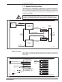
2.1
The Control Panel
The control panel is located on the front panel of the controller. It is used
for drive and fault diagnoses, checking and setting parameters. The
green LED indicates the drive is OK, the red LED comes on with a fault.
green
Ready
red
Parameter
Fault
operating
mode switch
display
keypad
with arrow keys for:
up
right
left
down
and accept key:
center
Figure 6: Control panel with legends
Operating mode
The mode switches enable the main spindle drive to be changed from the
operating mode to the parameter mode.
The main spindle drive is ready for power input or power output. The
mode switch is set to the right.
Parameter mode
Power output from the main spindle drive is inhibited. Parameters can be
checked and changed. The mode switch is set to the left.
• DOK-DIAX01-MAIN+2AD+1M-ANW1-EN-E1,44 • 07.97
27
2. Operating the Controllers
2.2
Main Spindle Drive in Operating Mode
The main spindle drive is ready for power input or output.
Choice of operating mode:
The mode selection switch must be set to the right. Control voltage must
be present.
Message in Display at Power Up:
If the unit is only supplied with control voltage, NO POWER is displayed.
Both LEDs are off. If the unit is ready for power output, NO RF is
displayed. The green LED comes on.
Operating mode switch
Display
NO POWER
or
NO RF
key
pad
internal state variable
output state
N=
motor speed
C=
torque command
value
S=
spindle feedback
speed
M=
torque load
(torque command
value)
spindle or
motor position
POS =
UD=
voltage in
DC bus (ZK)
ID=
current in
DC bus (ZK)
PD=
power in
DC bus (ZK)
T=
motor winding
temperature
P.......
signal states of
control inputs
Zustandsgr.
Figure 7: Internal state variables of the drive
• DOK-DIAX01-MAIN+2AD+1M-ANW1-EN-E1,44 • 07.97
28
2. Operating the Controllers
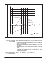
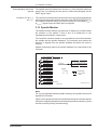
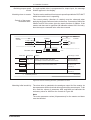
2.2.1 Displaying the Internal State Variables of the Drive
Exemplary
display:
R 5 3 1 2 1
P
Q
R
S
control inputs
PAR1 PAR2
(X2/30) (X2/31)
0V
0V
+24 V
0V
0 V +24 V
+24 V +24 V
0
1
2
3
4
5
6
7
control inputs
LIMIT 1 LIMIT 2 LIMIT 4
(X2/32) (X2/33) (X2/34)
0V
0V
0V
+24 V
0V
0V
0V
+24 V
0V
+24 V
+24 V
0V
0V
0V
+24 V
+24 V
0V
+24 V
0V
+24 V
+24 V
+24 V
+24 V
+24 V
control input
EXT POS
(X2/37)
0
0V
1
+24 V
control inputs
SPEED 1 SPEED 2
(X2/35)
(X2/36)
1 +24 V
0V
2
0V
+24 V
0
0V
0V
control input
MD-RED
(X2/28)
0
0V
1 +24 V
0
1
2
3
control inputs
POS 1
POS 2
(X2/35)
(X2/36)
0V
0V
+24 V
0V
0V
+24 V
+24 V
+24 V
Figure 8: Display of signal states of control inputs and assignment of digits
In operating mode, all the internal state variables of the drive that are
important for drive diagnostics can be called up into the display. This is
done by pressing the "up" and "down" arrow keys. The "down" key
enables the sequence shown in Figure 6 to be displayed in reverse order.
Both keys have a continuous function.
Note: Pressing the red central key (accept key) moves the display back
from the current position to the initial state. The signal states of the control
inputs are also displayed.
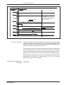
2.2.2 Outputting the Drive Internal State Variables for Analogue
Output N
Analogue output N (X23/21) is designed as a universal output. It outputs
voltage between -10 and +10 volts. The internal state variables of the
drive which are displayed can be switched to the analogue output N as
a voltage by pressing the LEFT arrow key. This is possible when the
control voltage is applied and allows the variations in the state variables
to be recorded with just one measuring set-up, e.g., via an oscilloscope,
when the drive is operating.
Note on Figure 8
All the state variables of the drive can be called up into the display when
the assignment of the analogue output N is unchanged. The contents of
the previous display can be restored or scrolled backwards by pressing
the DOWN key.
Pressing the red ACCEPT key resets the display to the initial state. The
assignment of analogue N output remains unchanged.
• DOK-DIAX01-MAIN+2AD+1M-ANW1-EN-E1,44 • 07.97
29
2. Operating the Controllers
Oper. mode switch
Analogue output N (X2/21)
Display
NO POWER
N=NCMD
NO RF
key
pad
Output status
Definition
Weighting
Motor speed
^ ± MAX RPM
± 10 V =
The last or the last set weighting
of the N output is maintained.
N
Motor speed,
high-resolution
Motor speed
^ ± 50 1/min
± 10 V =
over the entire
speed range
^ MAX RPM
± 10 V =
(value in parameter A01)
The last selected weighting of
the N output is maintained.
C
Speed command
value
^ MAX RPM
± 10 V =
(value in parameter A01)
Internal speed
command value
(after ramp)
^ MAX RPM
± 10 V =
(value in parameter A01)
The last selected weighting of
the N output is maintained.
S
Spindle
encoder speed
^ ± 10 000 1/min
± 10 V =
The last selected weighting of
the N output is maintained.
M
Torque command
value, no delay
^ drive-dependent
± 10 V =
torque command value
The last selected weighting of
the N output is maintained.
POS
Spindle position
^ ± 180 °
(motor position) in
± 10 V =
∠ degrees
Spindle position
^ 0.044 °
(motor position) in
- 10 V.....+ 10 V =
∠ deg. (high-resolution)
The last selected weighting of
the N output is maintained.
UD
voltage in DC
bus (ZK)
^ + 1000 V in the DC bus (ZK)
+ 10 V =
The last selected weighting of
the N output is maintained.
ID
current in
DC bus (ZK)
± 10 V ^= rated current of the control unit
The last selected weighting of
the N output is maintained.
PD
power in
DC bus (ZK)
± 10 V =^ ± 100 kW with RAC 2.2
± 50 kW with KDA 3 and RAC 3
The last selected weighting of
the N output is maintained.
T
motor winding
temperature
0...+ 10 V =^ 0...+ 150° C
The last selected weighting of
the N output is maintained.
P.......
Analog N
Figure 9: Switching the analogue output N ot the internal state variables of the drive
• DOK-DIAX01-MAIN+2AD+1M-ANW1-EN-E1,44 • 07.97
30
2. Operating the Controllers
2.3
Switching into parameter
mode
The Main Spindle Drive in Parameter Mode
The main spindle drive is not ready for either power input or output.
The parameters can be tested, read and changed. They are stored in an
EEPROM on the AS programming module.
The mode selection switch must be set to the left. Control voltage must
be present.
If parameter mode is selected when the motor is rotating, the
drive brakes to a standstill and remains without torque!
Message in display:
(P01...) appears when the parameter mode is selected for the first time
after the control voltage is applied. Otherwise, the parameter displayed
is the one which was current when the operating mode was reselected.
2.3.1 Parameter Value Quick-Check
The parameter values of a programming module are stored with a
parameter checksum. This is an advantage in that the many parameter
values can be characterized by a number.
The correspondence between the current parameter values of the main
spindle drive of a machine and the values in the parameter record in the
machine file can be checked by comparing the checksums.
In standard production machines, the parameter checksum provides a
rapid check indicating that the programming modules in use contain the
correct parameter values.
The parameter checksum does not contain the value of the OFFSET
parameter (A07) since this can differ, even in identical machines.
Operating mode switch
Display
e.g., P 01 . . . . .
SUM . . . . .
key
pad
output state
first press
"accept key"
and keep
pressed then
press "
"
also.
Definition
parameter in display
checksum in display
Param.-Prüfsumme
Figure 10: Parameter checksum display
• DOK-DIAX01-MAIN+2AD+1M-ANW1-EN-E1,44 • 07.97
31
2. Operating the Controllers
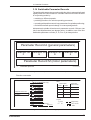
2.3.2 Reading the Parameters
The parameter values can be called up into the display in the parameter
mode. They are subdivided into six parameter records:
Parameter Record A (general parameters)
Parameter rec. Parameter rec. Parameter rec. Parameter rec.
P
Q
R
S
Parameter Record M (motor parameters)
☞
Parameter protocol!
6 Parametersätze
Figure 11: The six parameter records of Indramat main spindle drives
Parameter records A and M are permanently active, so is one of the four
selectable parameter records P, Q,R or S.
Reading a parameter record
The parameter number, value and name can be displayed via the
keyboard.
Changing to another
parameter record
The other parameter records have to be displayed in order to read all the
parameters. After changing to one of the other parameter records, the
system for reading the parameter records as described is repeated.
Operating mode switch
Display
P 01 . . . . .
key
pad
output state
Definition
parameter no. P 01
with value
RAMP 1
parameter name
display
P 01 . . . . .
automatic return to
parameter number
P 02 . . . . .
parameter no. P 02
with value
RPM 1
parameter name
display
P 02 . . . . .
automatic return to
parameter number
P 03 . . . . .
parameter no. P 03
with value
.
.
.
.
.
.
.
.
.
and so on
Figure 12: Reading a parameter record, e.g., parameter record P
• DOK-DIAX01-MAIN+2AD+1M-ANW1-EN-E1,44 • 07.97
32
2. Operating the Controllers
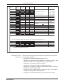
Recording the parameter
values
A parameter form for listing parameters is in section 5. This allows the
values as supplied, and those modified by the user, to be recorded.
The permissible ranges of parameter values are also shown in the form.
Operating mode switch
Display
pad
key
output state
P 06 . . . . .
(any)
P 06 . . . . .
Definition
display of a
P parameter
ready to leave
P parameters
2x
Q 06 . . . . .
change in
Q parameters
Q 06 . . . . .
number activating
for scrolling
R 06 . . . . .
change in
R parameters
.
.
.
.
.
.
and so on
Wec
Figure 13: Changing the displayed parameter records
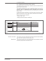
2.3.3 Changing the Parameters
The user parameters (A, P, Q, R and S) are given default values at the
factory. Parameter values may need to be changed to match the drive to
a special application.
The drive-specific motor parameters (m) have been optimized at the
factory. They may only be modified by trained personnel, as otherwise
the drive can be damaged. Exceptions are the M03 T-filter and M15
MOTFUNCT parameters (see section 5, parameter overview or list).
The parameter values are protected against unintentional modification
by a code.
• DOK-DIAX01-MAIN+2AD+1M-ANW1-EN-E1,44 • 07.97
33
2. Operating the Controllers
When a parameter gets a new value it must be transferred into the
memory of the programming module by pressing the red key ("accept
key").
Oper. mode switch
Display
pad
key
Definition
Initial state
e.g. A 07 . . . . .
lockout for accessing
parameter values
LOCKED
code for
2x
changing
parameter
values
2x
A 07 . . . . .
changing the
para. value
changing the numbers
(continuous function)
A 07 . . . . .
changing to different
decimal place of
the parameter value
new parameter value
assuming the new
value into the
programming module
A 07 . . . . .
Figure 14: Changing the values in parameter records A, P, Q, R and S
Note:
The controller accepts the new value into memory if the LEFT key is
pressed after the parameter value has been changed. The parameter
number flashes and the old value is displayed.
Oper. mode switch
Display
M 07 . . . . .
key
pad
Definition
Initial state
lockout for accessing
parameter value
LOCKED
code for
changing
the parameter
value
changing the
para. value
M 07 . . . . .
changing the number
new parameter value
M 07 . . . . .
changing to a different
decimal place of the
parameter value
assuming the new
value into the
programming module
Figure 15: Changing the parameters in parameter record M
• DOK-DIAX01-MAIN+2AD+1M-ANW1-EN-E1,44 • 07.97
34
2. Operating the Controllers
There is a risk of damage from modified motor parameter
values. To start up the drive again with the new parameters, the
mode switch must be moved to the right. The message "RFAGAIN" appears in the display. The RF control input must be
switched from 0 to + 24 volts.
Possible fault
messages
Possible fault message:
UNACCEPT
Cause:
Invalid parameter combination
Remedy: Move operating mode switch to left and press the red key.
The incorrect parameter is displayed. Enter a valid value.
Possible fault message:
FEEDBACK
Cause:
Type of motor feedback and value in M02 do not coincide.
Remedy: Move mode switch to left. Enter correct value (see 5.3).
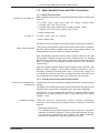
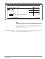
2.3.4 Displaying the Software Version
Apart from the drive parameters, the AS programming module also holds
the operating software. The name of the installed software can be
Operating mode switch
Display
e.g., Q 11 . . . . .
key
pad
output state
(any)
Q 01 . . . . .
e.g., RAC 4 V 1.3
☞
Definition
displayed
parameter
return to
first parameter
quick display of
software version,
automatic return
PARAMETER PROTOCOL !
Figure 16: Software version display
called up on the display. The software version should be noted on the
parameter form. It can be important when dealing with questions about
applications.
2.3.5 Duplicating the Parameters
The parameter values of a programming module (master) can be copied
to another (slave) for the same controller. This produces another
programming module with the same parameter contents.
This enables
• parameter values to be protected (back-up copy) and
• programming modules to be rapidly provided with the necessary
parameters for mass-produced machines.
Prerequisite:
Parameter duplication adapter PDA 1
• DOK-DIAX01-MAIN+2AD+1M-ANW1-EN-E1,44 • 07.97
35
2. Operating the Controllers
Procedure:
• Switch off main drive. Control voltage must not be present.
• Unplug programming module AS and replace with PDA 1.
• Plug the master programming module into the „MASTER“ connector.
• Plug the slave programming module into the „SLAVE“ connector.
• Move the operating mode switch to the left.
• Switch on the control voltage. The display now shows the checksum
of the master module and a rotating pointer, i.e., transfer running (up
to 30 seconds). If the mode switch is not set to the left-hand position,
the prompt "SWITCH" appears and the transfer commences when the
switch is moved to the left. At the end of the transfer, the display reads
"SWITCH->".
• The mode switch must now be set to the right so that the contents of
the slave EEPROM cannot be destroyed during any subsequent
power down. If the switch is in the right-hand position, the checksum
of the slave EEPROM appears along with the request to switch off the
control voltage, e.g., "4B13 OFF".
• Switch off the control voltage and remove the slave module.
• If no further duplicates are to be made, replace the PDA 1 with the
master programming module.
Do not remove the programming module when power is on. The
slave module is erased if no master module is plugged in.
During duplication, only the contents of the master EEPROM
are transferred to the slave EEPROM. The system software is
ignored. The checksums of the master and slave EEPROMs are
not compared.
Possible fault messages
Possible fault message:
EEPROM
Cause:
EEPROM of slave module cannot be programmed.
Remedy: Switch the unit off and use a new slave module.
Possible fault message:
PARALOST
Cause:
Programming module has no parameters. Values are not
loaded or parameters in software of master and slave modules do not
agree.
Remedy: Move mode switch to left and press the red key. This loads
the general parameters with which the drive can be put into service. If the
message "BASISPART" appears in the display, the loading cycle is
complete. Pressing the red key once again puts the drive into the
parameter mode. The basic parameters are not optimized for the drive
and they should be replaced by optimized values (AS/..).
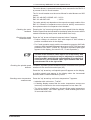
2.3.6 Loading Operating Parameters via Serial Interface
Prerequisite: Serial interface on controller. (Type code field "additional
interfaces": S), device for data input such as PC, magnetic tape,
perforated tape or other control unit.
Purpose: Rapid input of parameters for mass production machines.
Parameters can be printed out. For details on data transfer process see
section 3.22, "Serial Interface".
• DOK-DIAX01-MAIN+2AD+1M-ANW1-EN-E1,44 • 07.97
36
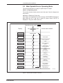
3. Controller Functions
3.
Controller Functions
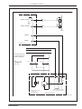
3.1
Drive "Ready" State
The main spindle drive is "ready" when the following conditions are met:
• All controller signal voltages must be present.
• The control inputs and signal ouputs (terminal strip X2) must be
supplied with ±24 V and 0 V. The supply voltage should be provided
via the external controller, but the internal +24V can also be used.
• The motor and controller temperatures are within permissible range:
motor winding 0 < J < 155° C
controller heatsink 0 < J < Jmaxperm
• The mode switch must be to the right.
• There must be no fault message in the display.
• The DC bus voltage must be present.
• For an RAC the „E-Stop“ control input must be at 1.
• For KDA3/TDA 1 the "AS" (starting lockout) control input must be at 1.
The "ready" state of the drive can be evaluated via the "READY" signal
output and the "Bb" potential-free contact.
X2 control inputs
1
bridge if 0V / +24V
is not supplied by
controller
from the controller
1
0V
+24V
^ "ready" message
1=
23
24
25
26
27
28
29
30
31
32
33
34
35
36
37
3
2
18
1
19
E-STOP (RAC only)
RF
RUN
POS 1
POS 2
MD-RED
OSCILATE
PAR 1
PAR 2
LIMIT 1
LIMIT 2
LIMIT 4
SPEED 1
SPEED 2
EXT POS
AS (KDA/TDA only)
0 V int
+ 24 V int
input 0 V ext
input + 24 V ext
control unit
Legend:
^ +24V
1=
^
0 = 0V
=^ signal step
^ any control
=
state
X2 signal output
4 READY
X15 ( for RAC ) X11 ( for KDA/TDA )
relay contact
" Bb "
Steuereingaenge
Figure 17: Control inputs and signal output, „Bb“ potential-free contact
"Ready" display
If the drive is "ready", it can start operating with the available functions.
The green "READY" LED comes on. If there is a fault in the drive, the
green "READY" LED is off, the red "FAULT" LED comes on and the fault
message flashes in the display.
• DOK-DIAX01-MAIN+2AD+1M-ANW1-EN-E1,44 • 07.97
37
3. Controller Functions
3.2
Performance features
Speed Command Value
The speed command value can be communicated to the control devices
from the controller via an analogue voltage or digitally via a bit pattern.
Feature: very broad speed range from minimum speed of 0.0005 rpm to
maximum speed.
In addition, Indramat main spindle drives offer a far more powerful type
of command value input via the "SERCOS interface" option (see section
3.2.1).
The speed command value is read at 1.2 ms intervals.
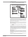
3.2.1 Analogue Speed Command Value (option)
The drive with interface for analogue speed command value is designed
for multiple applications:
• as a main spindle drive
• as a positioning drive with various gear ratios
• as a C-axis drive for lathes
The differential input provides a large degree of decoupling between NC
controller and control unit. Command value voltage matching is easily
carried out. Excessive N command value produces only specified
maximum speed.
One of the two available command value inputs is always active.
Suitable command value weighting is required for positioning, depending
on the gear reduction ratio. C-axis operation requires high resolution for
the speed command value.
Command value weighting for various speeds and C-axis operation is
obtainable via parameter records (PQRS).
Function conversion
The control unit must be fitted with the analogue command value
interface (type code field "speed command value = A").
Note:
For noise immunity reasons (earth loops), connect screen of command
value cable to controller only!
Avoid running command value line and power cable in parallel!
• DOK-DIAX01-MAIN+2AD+1M-ANW1-EN-E1,44 • 07.97
38
3. Controller Functions
X4 analogue inputs
analogue
voltage
± 10V
1 (E1)
2 (E2)
analogue
voltage
± 10V
5(E3)
6(E4)
control unit
4
P
1
1
^ speed command
1=
value output
0
switching to
parameter records PQRS
(see table)
^ switching to input
1=
weighting to the
P - MAXRPM of the active
parameter record (PQR or S)
Table:
control inputs
1
X2
23
24
25
26
27
28
29
30
31
32
33
34
35
36
37
3
Q
control inputs
E-STOP (RAC only)
RF
RUN
POS 1
POS 2
MD-RED
OSCILATE
PAR 1
PAR 2
LIMIT 1
LIMIT 2
LIMIT 4
SPEED 1
SPEED 2
EXT POS
AS (KDA/TDA only)
active
parameter record
PAR 1
PAR 2
0
0
P
1
0
Q
0
1
R
1
1
S
R S16
Legend:
^ +24V
1=
^
0 = 0V
=^ signal step
^ any control
=
state
Drehzahlsollwert
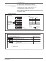
Figure 18: Inputs for analogue speed command value and control inputs
Parameter
Designation
Function
Value range or value
A 01
MAX RPM
maximum motor speed
1.....24000
( 1/min )
A 02
CMD VOLT
analogue voltage value
6.0.....10.0
(V)
( 1/min )
P
Q
R S 15
P-MAXRPM
motor speed for additional input weightings
1.....24000
P
Q
R S 16
PQ-FUNCT
switching analogue inputs with
switching of input weighting
<1>
A 05
FUNCT 1
analogue speed command value below
MIN RPM is invalid!
<2>
A 03
MIN RPM
speed limit
1.....999
A 06
FUNCT 2
with EXTPOS = 1 is at analogue
output N: 10V = P-MAXRPM
< 128 >
☞ PARAMETER PROTOCOL !
( 1/min )
Para-Sollwert-Analog
Figure 19: Parameter for analogue speed command value
• DOK-DIAX01-MAIN+2AD+1M-ANW1-EN-E1,44 • 07.97
39
3. Controller Functions
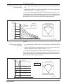
Input weighting
Note: Command value wieghting is CMDVOLT/MAXRPM, if control
input EXTPOS is at 0.
If control input EXTPOS is at 1, then the weighting is CMDVOLT/PMAXRPM. P-MAXRPM is part of the selected parameter record (P, Q, R
or S). The voltage at the analogue output N can be output with parameter
FUNCT2 with reference to P-MAXRPM.
Input switching
Changing to the second differential input is effected with the EXTPOS
control unit. In this case, the value in parameter PQ-FUNCT must be
increased by <1> and EXTPOS must be at 1.
Maximum/minimum speed
command value
If the value of parameter CMDVOLT is less than 10 V, 10% of MAXRPM
can be obtained by suitable voltage input. To prevent drift if the speed
command value zero is affected by noise, a command value less than the
value in the parameter MINRPM can be arranged to be invalid.
Speed limiting
Possible error messages in
the display
RPM is limited to 112 % of MAXRPM in the event of a fault!
• ADW2
• NO INPUT
• DOK-DIAX01-MAIN+2AD+1M-ANW1-EN-E1,44 • 07.97
40
3. Controller Functions
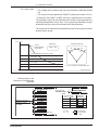
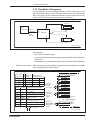
3.2.2 Digital Speed Command Value (option)
The "digital speed command value" enables a task to be matched to the
specific plant requirements.
The speed command value can be transferred directly from the PLC
controller, binary or floating-point coded, depending on the required
speed resolution. The parallel signals are interrogated by the control unit
every 1.2 ms.
In plants with severe interference, and in the case of long lines, digital
parallel transmission ensures high speed command value accuracy.
Speed command value resolution:
• binary coded 1 rpm
• floating-command coded to 0.0005 rpm
Parameter
Designation
Function
Value range or value
A 06
FUNCT 2
dig. speed comm. value, binary coded
<0>
dig. speed comm. value, floating comma coded < 2 >
A 01
MAXRPM
maximum speed of the motor
A 05
FUNCT 1
weighting change of the digital speed command < 1024 >
value with respect to parameter value of A 01:
1....24000
( 1/min )
A 01
N
=
comm
A 01
16383
• N
comm
digital
☞ PARAMETER PROTOCOL !
Para-Sollwert-Digital
Figure 20: Parameters for a digital speed command value
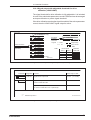
Function conversion
The control unit must be fitted with the digital command value interface
(type code field "speed command value = D").
Speed limits
The maximum speed of the motor MAX RPM is not exceeded, even with
excessively high speed command values!
• DOK-DIAX01-MAIN+2AD+1M-ANW1-EN-E1,44 • 07.97
41
3. Controller Functions
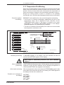
Binary Coding
X2 control inputs
X4 inputs for digital command value:
command
value in
binary code
"0" =^ 0 1/min
^ assume
1=
current bit
pattern
Bewertung-binär
E-STOP ( RAC only)
1
RF
2
^ output
1=
RUN
3
of speed
POS 1
4
command
POS 2
5
value
MD-RED
6
0
OSCILATE
7
PAR 1
8
PAR 2
9
LIMIT 1
10
LIMIT 2
11
LIMIT 4
12
SPEED 1
13
1 ^= reduction of the
SPEED 2
14
command value
EXT POS
15
by a factor of 100
1
AS (KDA/TDA only)
16
17
Table:
control unit
18 - 15V int
control input
19 + 15V int
N COMM max
EXTPOS
N COMM min
20
1
16383
0
21
0V ext
0.01
163.8
1
22
0V ext
Legend:
23
^ +24V
1=
=^ signal step
24 *) 0 - clockwise
^
^ any control
1 - counterclockwise
0 = 0V
=
25
control unit
state
Bit 1
1=^ 1/min
^
Bit 2 1 =
2 "
^
Bit 3 1 =
4 "
^
Bit 4 1 =
8 "
^
Bit 5 1 =
16 "
^
Bit 6 1 =
32 "
^
Bit 7 1 =
64 "
^ 128
Bit 8 1 =
"
^ 256
Bit 9 1 =
"
^ 512
Bit 10 1 =
"
^ 1024
Bit 11 1 =
"
^ 2048
Bit 12 1 =
"
^ 4096
Bit 13 1 =
"
^ 8192
Bit 14 1 =
"
rotational dir.: *)
Bit 15
DATA VALID
1
1
23
24
25
26
27
28
29
30
31
32
33
34
35
36
37
3
Figure 21: Inputs for digital speed command values, weighting for binary coding and
control inputs
Speed command value
validity
If the "DATA VALID" input is at 1, then the bit pattern is read continuously
and is passed to the processor.
If the „DATA VALID“ input is at 0, then the bit pattern last read and passed
to the processor is the effective speed command value.
• DOK-DIAX01-MAIN+2AD+1M-ANW1-EN-E1,44 • 07.97
42
3. Controller Functions
Floating-Point Coding
X2 control inputs
X4 inputs for digital command value:
exponent
mantissa
^ 0 1/min
"0" =
^ assume
1=
current bit
pattern
1
2
3
4
5
6
7
8
9
10
11
12
13
14
15
16
17
18
19
20
21
22
23
24
25
BewertungFließkomma
Bit 1
1
^
Bit 2
2
1=
^
Bit 3
4
1=
^
Bit 4
8
1=
^
Bit 5
1 = 1/min
1=
^
"
Bit 6
2
1=
^
"
Bit 7
4
1=
^
"
Bit 8
8
1=
^ 16
"
Bit 9
1=
^ 32
"
Bit 10
1=
^ 64
"
Bit 11
1=
^ 128
"
Bit 12
1=
^ 256
"
Bit 13
1=
^ 512
"
Bit 14
1=
Bit 15
rotational dir.:"*)
DATA VALID
^ output of
1=
speed
command
value
1
1
0
1
23
24
25
26
27
28
29
30
31
32
33
34
35
36
37
3
E-STOP (RAC only)
RF
RUN
POS 1
POS 2
MD-RED
OSCILATE
PAR 1
PAR 2
LIMIT 1
LIMIT 2
LIMIT 4
SPEED 1
SPEED 2
EXT POS
AS ( KDA/TDA only)
control unit
- 15V int
+ 15V int
N COMM= mantissa * 2(exponent -11)
minimum command N COMM = 0.00049 1/min
0V ext
maximum command N COMM = 16368 1/min
0V ext
Control input EXTPOS irrelevant here!
^ +24V
^ = signal step
*) 0 - clockwise
Legend: 1 =
1 - counterclockwise
^
^
0 = 0V
= any control
control unit
state
Figure 22: Inputs for digital speed command value, weighting for floating-point
coding
Speed command value
validity
If the "DATA VALID" input is always at 1, the bit pattern is read
continously and is passed to the processor.
If the "DATA VALID" input goes to 0, then the bit pattern last read and
passed to the processor is the effective speed command value.
Possible error message in
display
NO INPUT
• DOK-DIAX01-MAIN+2AD+1M-ANW1-EN-E1,44 • 07.97
43
3. Controller Functions
3.3
Main Spindle Speed Signals
The main spindle speed determines the time point of the feed enabling
signal, gear change and clamping of the holding brake.
Function conversion
The requirements are met if signal output „Nact = Ncomml“, „N < Nmin“ and the
selectable torque disconnect is below Nmin . The signal operating thresholds
can be set as required.
X2 control inputs
1
^
1=control
enable signal
1
1
^ speed command
1=
value output
0
1
23
24
25
26
27
28
29
30
31
32
33
34
35
36
37
3
E-STOP (RAC only)
RF
RUN
POS 1
POS 2
MD-RED
OSCILATE
PAR 1
PAR 2
LIMIT 1
LIMIT 2
LIMIT 4
SPEED 1
SPEED 2
EXT POS
AS (KDA/TDA only)
Table:
Display
messages
N = CMD
N < MIN
N = NCMD
1
0 or 1
N * NCMD
0
0 or 1
N < NMIN
Legend:
Signal outputs
0 or 1
^ +24V
1=
^ 0V
0=
1
=^ signal step
^ any control
=
state
^ message
1=
" N act = N comm "
X2 signal outputs
5 N = CMD
6 N < MIN
^ message
1=
" N act < N min "
control unit
Hauptspindeldrehzahl
Figure 24: Control inputs, signal outputs, displays for main spindle speed
Note:
The display message „N * NCMD“ means Nact ≠ Ncomm. This appears when
the speed is above the minimum speed, but has not yet reached the
command value speed.
Parameter Designation
Function
Value range or value
A03
MIN RPM
if speed command value and motor speed are under
MIN RPM, then signal output "N < MIN" goes to 1
1.....999
( 1 / min )
A04
MAX DEV
1.....999
( 1 / min )
A05
FUNCT 1
maximum deviation of speed from command value
within which signal output " N = CMD " goes to 1
signal output " N = CMD " also signals
without RF enabling signal (control input RF = 0)
change of input value of " MAX DEV ";
1 = 0.1% of current Ncommand
< 512 >
torque off if speed is less than
value in MINRPM
independent of speed command value, signal output
"N < MIN" goes to 1 if motor speed less than
MIN RPM (A 03)
<4>
P Q R S 16
PQ-FUNCT
☞
Parameter protocol !
< 256 >
< 512 >
Parameter Hauptspindel
Figure 25: Parameter for main spindle speed signals
Note: When the values of parameter „MAX DEV“ (A04) are input as per
cents of the speed command value, then the smallest deviation is limited
to 10 rpm.
• DOK-DIAX01-MAIN+2AD+1M-ANW1-EN-E1,44 • 07.97
44
3. Controller Functions
Motor standstill
Furthermore, when the drive is stopped with the controller enable signal
switched off (RF contol input=0), the controller can check standstill via
the signal output "N=CMD" (speed command value must be 0!).
Torque disconnect
Torque disconnection is compatible via function parameters if the motor
speed is less than the value in parameter MINRPM. This is useful if the
motor has to be locked in the stopped position after controller braking, but
the controller enabling signal does not have to be disconnected.
The signal „N < MIN“ does not meet personnel protection
needs in the working area of the main spindle!
3.4
Speed Command Value Ramps
In many cases in main spindle drives it suffices to apply the speed
command value via simple control devices (PLC and the like). Sudden
changes in the speed command value can be converted in the control
unit to ramp-type characteristics.
Three different selectable, successive ramp slopes are available in the
controller. They can be used, for example, for breakaway damping and
limiting the acceleration for belt couplings. In the constant-power range,
the torque is reduced via the speed. In this case, the regulation can be
maintained in the active area by means of the third ramp (constant speed
increase).
Different ramp slopes can be entered for a maximum of four speed
reduction stages.
X2 control inputs
^ E-Stop
0=
^ control enable signal
1=
^ command enable
1=
0
^ weighting changeover
1=
1
23
24
25
26
27
28
29
30
31
32
33
34
35
36
37
3
control unit
E-STOP (RAC only)
RF
RUN
POS 1
POS 2
MD-RED
OSCILATE
PAR 1
PAR 2
Legend:
LIMIT 1
LIMIT 2
^ +24V
1=
LIMIT 4
^
0 = 0V
SPEED 1
SPEED 2
EXT POS
AS (KDA/TDA only)
=^ signal step
^ any control
=
state
Drehzahlsollwertrampen
Figure 26: Control inputs affecting the speed command value ramps
Ramps
The specified ramps are active when the controller enabling signal (RF)
and the speed command value enable signal (RUN) are switched on and
off!
• DOK-DIAX01-MAIN+2AD+1M-ANW1-EN-E1,44 • 07.97
45
3. Controller Functions
Parameter
S R Q P01
Designation
Function
Value range or value
RAMP 1
ramp 1 switched off
0
gradient of ramp 1
1.....999
(rad / s2)
(1 / min)
S R Q P02
RPM 1
end speed of ramp 1
1.....24000
S R Q P03
RAMP 2
ramp 2 switched off
0
gradient of ramp 2
1.....999
(rad / s2)
(1 / min)
S R Q P04
RPM 2
end speed of ramp 2
1.....24000
S R Q P05
RAMP 3
ramp 3 switched off
0
gradient of ramp 3
1.....999
A06
FUNCT 2
(rad / s2)
the ramp set is also active
- switching EXT POS and power failure (all controllers)
< 32 >
- switching of E-STOP (RAC only)
☞
Parameter protocol !
Para.Drehzahlsollwertrampe
Figure 27: Parameters for speed command value ramps
If the ramps are to remain active during a change of weighting (EXT
POS), during an E-stop and mains off, this must be specified via function
parameters.
Note:
All three ramps must be set when the ramp function is used. Slopes must
be entered in rad/s2 (see Figure 27 for conversion).
• DOK-DIAX01-MAIN+2AD+1M-ANW1-EN-E1,44 • 07.97
46
3. Controller Functions
∆ t/s
3
Example 1:
∆ N = 5000 1/min
in ∆ t = 2s
⇒ RAMP = 250
2
rad
s2
Example 2:
∆ N = 9000 1/min
in ∆ t = 1s
⇒ RAMP = 940
500 ( RAMP axis)
100
rad
s2
1000
RAMP /
1
rad
s2
∆ N/rpm
origin
1000
☞
5000
Parameter protocol!
10000
Umrechnung von Drehzahl
Figure 28: Converting speed ∆N and slope times ∆t in RAMP (rad/s2)
Instructions for using the
conversion graph
Slope values must be entered in rad/s2 (see Figure 28 for conversions).
• Determine your desired end speed ∆N in rpm and the necessary time
period ∆t in seconds (s).
• Mark the point corresponding to the combined values of ∆N and ∆t on
the graph.
• Draw a straight line through the marked point and the origin of the
graph.
• Read the slope of your desired ramp in rad/s2 at the intersection of the
straight line and the RAMP axis and enter the respective RAMP
parameter (see example).
Conversion formula (alternative to conversion graph)
RAMP = π/30* ∆N/∆t*min/s (∆N in rpm and ∆t in s)
• DOK-DIAX01-MAIN+2AD+1M-ANW1-EN-E1,44 • 07.97
47
3. Controller Functions
Function sequence graph
Drehzahlrampen Sprung
^
U analogue = A01
( CMD VOLT )
speed
command
value, e.g.,
analogue
( MAX RPM )
A01
motor
speed
S R Q P05
S R Q P04
( RPM2 )
S R Q P02
( RPM1 )
( RAMP2 )
S R Q P03
S R Q P01
( RAMP3 )
( RAMP1 )
time t
Figure 29: Speed ramps for step change in speed command value
3.5
Command Value Smoothing
When controlling the main spindle drive along a ramp via the NC
controller or when operating in positioning mode, staircase changes in
command values by the NC controller cause sudden torque changes.
The speed command value can be smoothed to dampen these.
Adjustable smoothing time constants provide matching to different NC
clock times and mechanical conditions for the various speed reduction
stages!
X2 control inputs
1
1
1
0
^ weighting changeover
1=
1
23
24
25
26
27
28
29
30
31
32
33
34
35
36
37
3
E-STOP (RAC only)
RF
RUN
POS 1
POS 2
MD-RED
OSCILATE
PAR 1
PAR 2
LIMIT 1
LIMIT 2
LIMIT 4
SPEED 1
SPEED 2
EXT POS
AS (KDA/TDA only)
control unit
Legend:
^ +24V
1=
^ 0V
0=
=^ signal step
^ any control
=
state
Drehzahlsollwertglättung
Figure 30: Control inputs affecting speed command value smoothing
Smoothing and weighting
selection
Note: The speed command value smoothing is inoperative when the
input weighting (EXTPOS=1) is changed. However, it can be made
operative via parameters when EXTPOS=1.
• DOK-DIAX01-MAIN+2AD+1M-ANW1-EN-E1,44 • 07.97
48
3. Controller Functions
Parameter
Designation
Function
Value range or value
S R Q P01
RAMP 1
Value for smoothing time constant
0 to 11
S R Q P02
RPM 1
no function, but defined value 0 is needed!
0
S R Q P03
RAMP 2
"
"
"
"
"
"
0
S R Q P04
RPM 2
"
"
"
"
"
"
0
S R Q P05
RAMP 3
"
"
"
"
"
"
0
A06
FUNCT 2
the smoothing set is also active with:
< 32 >
control input EXT POS = 1
☞
Parameter protocol!
Para-Drehz-Glätt
Figure 31: Parameters for smoothing speed command value
Smoothing time constant
Note: Smoothing is achieved via a digital filter. The smoothing time
constant is calculated as follows:
Tg = 0.5 x 2RAMP1 ms
In the same parameter record the speed command value smoothing
excludes the speed ramp function.
Speed command value smoothing is possible for both analogue and
digital command values.
• DOK-DIAX01-MAIN+2AD+1M-ANW1-EN-E1,44 • 07.97
49
3. Controller Functions
3.6
Spindle Positioning
Three standard spindle positions can be set for the drive via the controller
for simple and rapid tool change on milling centers.
If more than three positions are required, for example,
• for aligning the tool to the workpiece contour on milling machines,
• indexing the workpiece on lathes, or,
• positioning workpieces for balance holes on balancing machines,
then 3600 optional selectable spindle positions are available.
Positioning accuracy
The position command values can be accurately set to 0.1 angular
degrees and are corrected to a maximum of 1/1000th of an angular
degree.
Three modes of mechanical coupling between motor and spindle make
different types of positioning possible.
types of
mechanical
coupling
Spindle positioning with the use of.....
positioning
process
rigid gears, i = 1 : 1
... motor feedback
... motor feedback +
spindle homing switch
... spindle feedback
X
X
changeover gears, i = any
gears with slip,
i = any
X
see sections
3.6.1 and 3.6.2
see sections
3.6.1 and 3.6.3
see sections
3.6.1 and 3.6.4
Mechanische Kopplung
Figure 32: Mechanical coupling and positioning methods
• DOK-DIAX01-MAIN+2AD+1M-ANW1-EN-E1,44 • 07.97
50
3. Controller Functions
The three spindle positioning methods:
power
input
control
unit
power
output
X2
X3
spindle
and
rotor
position
spindle
positioning
Starres-Getriebe
2AD main spindle motor
Starres-Getriebe
Figure 33: Spindle positioning via motor feedback with solid gearing, i = 1
power
input
controller
power
output
X2
spindle reference switch
X3
reference switch signal
spindle
positioning
Starres-Getriebe
rotor
position
2AD Main Spindle Motor
Schalt-Getriebe
Figure 34: Spindle positioning via motor feedback with spindle reference switch and
change speed gear
power
input
incremental encoder
spindle position
X5
controller
power
output
X2
X3
spindle
positioning
Starres-Getriebe
rotor
position
2AD Main Spindle Motor
Schlupft-Getriebe
Figure 35: Spindle positioning via spindle feedback with gearing subject to slip
• DOK-DIAX01-MAIN+2AD+1M-ANW1-EN-E1,44 • 07.97
51
3. Controller Functions
3.6.1 Basic Data for Spindle Positioning
Function conversion:
a) Standard version - three spindle positions
• Inhibit the speed command value at the control unit by removing the
RUN control signal from the PLC.
• Binary selection of one of the three spindle positions via control signals
POS1 and POS2 from the PLC.
Table:
control inputs
selected
spindle position
X2 control inputs
POS 1
POS 2
parameter
0
0
no position
1
0
position 1
A08
0
1
position 2
A09
1
1
position 3
A10
1
1
^ inhibit speed
0=
command value
select spindle
position
(
0
All spindle positions relate to
parameter A07
Legend:
^ +24V
1=
^
0 = 0V
(OFFSET)
=^ signal step
^ any control
=
state
1
E-STOP (RAC only)
RF
RUN
POS 1
POS 2
MD-RED
OSCILATE
PAR 1
PAR 2
LIMIT 1
LIMIT 2
LIMIT 4
SPEED 1
SPEED 2
EXT POS
AS (KDA/TDA only)
X2 signal outputs
1 ^= "position reached"
(tolerance window P-WINDOW P Q R S21
23
24
25
26
27
28
29
30
31
32
33
34
35
36
37
3
7 INPOS
)
control unit
Spindelpos Standard
Figure 36: Control inputs and signal outputs for spindle positioniong (standard unit)
Note:
If "no position" has been selected, the drive brakes to a standstill and
remains under speed control without drift. The display then shows NO
RUN.
The drive switches back to speed control when the speed command
value is enabled (RUN = 1).
• DOK-DIAX01-MAIN+2AD+1M-ANW1-EN-E1,44 • 07.97
52
3. Controller Functions
Parameter
Designation
Function
Value range or value
A07
OFFSET
angular offset of the zero pulse and the spindle reference point
0.....360.0
(°)
A08
POS 1
spindle position 1
0.....360.0
(°)
A09
POS 2
spindle position 2
0.....360.0
(°)
A10
POS 3
spindle position 3
0.....360.0
(°)
A06
FUNCT 2
- shortest path < 0 >
positioning direction
(valid in all switching parameter
records PQRS)
- relevant qualifying sign
of speed command value
S R Q P16
PQ-FUNCT
< 16 >
- shortest path < 0 > (A06 ≠ < 16 > !!)
positioning direction
valid only in the presently
active PQRS parameter record;
A06 may not be <16> !
- relevant qualifying sign
of speed command value < 128 > (A06 ≠ < 16 >!)
S R Q P17
POS GAIN
gain factor in position control loop 16.6 = Kv = 1
0.....99.9
(1/s)
S R Q P18
POS RPM
positioning speed (limited to 30*POSGAIN)
0.....9999
(1/min)
S R Q P21
P-WINDOW tolerance window within which the message "INPOS" is issued
S R Q P12
GEAR IN
gear ratio i=
GEAR OUT
S R Q P13
☞
N1
N2
0.01.....99.99
N1
1.....999
N2
1.....999
Parameter protocol !
(°)
Para-Spindel
Figure 37: Parameters for spindle positioning (standard)
Note:
The parameter values refer to the spindle.
The spindle position values refer to the OFFSET values (for details on
OFFSET, see positioning procedure).
Direction of positioning
The direction of positioning can be specified in the FUNCT 2 parameter
(A06) for the shortest path or according to the sign of the applied speed
command value. This arrangement is then valid in each of the selectable
parameter records P, Q, R and S.
Changing the direction of
positioning
If the positioning direction has to be specified for each of the selectable
parameter records via PQ FUNCT (PQRS 16), then A06 must not contain
the value <16>!
• DOK-DIAX01-MAIN+2AD+1M-ANW1-EN-E1,44 • 07.97
53
3. Controller Functions
3600 spindle positions
Precondition is that the interface for digital position input must be fitted
to control unit (type code field "additional interface" = D).
inputs for digital position value:
X6 with KDA /TDA; X13 with RAC
BCD- coded
position
default
^
1 = bit pattern
connection
X2 control inputs
1
1
1
1 * 0.1°
2
2 * 0.1°
^ N command
0=
3
4 * 0.1°
value locked
0
4
8 * 0.1°
out
0
5
1 * 1°
6
2 * 1°
0
7
4 * 1°
8
8 * 1°
9
1 * 10°
10
2 * 10°
11
4 * 10°
12
8 * 10°
13
1 * 100°
14
2 * 100°
15 positioning direction: *)
1
DATA VALID
16
17
18 - 15V int
19 + 15V int
^ "position reached"
1=
20
( within tolerance window
21
0V ext
P-WINDOW
22
0V ext
P Q R S21
)
23
*) 0 - shortest path
Legend:
24
1 - as per command value
^ +24V
25
1=
control unit
^
0 = 0V
23
24
25
26
27
28
29
30
31
32
33
34
35
36
37
3
18
E-STOP (RAC)
RF
RUN
POS 1
POS 2
MD-RED
OSCILATE
PAR 1
PAR 2
LIMIT 1
LIMIT 2
LIMIT 4
SPEED 1
SPEED 2
EXT POS
AS (KDA/TDA)
X2 signal output
7 INPOS
control unit
=^ signal step
^ any control
=
step
Eingangsbelegung
Figure 38: Allocation of inputs for digital position command, control inputs and signa
outputs
Entering position command
value
Note:
The applied speed command value must also be inhibited when entering
digital position command values (RUN control input must be 0).
The bit pattern at the digital interface is switched through to the control
unit by means of the DATA VALID input. If the bit pattern changes while
the DATA VALID input is at 1, the drive moves immediately up to the new
position.
Priority of the position
command value
The three parameter-specific positions have priority over the digital
position input. The control inputs POS1 and POS2 must therefore be set
to 0!
• DOK-DIAX01-MAIN+2AD+1M-ANW1-EN-E1,44 • 07.97
54
3. Controller Functions
Parameter
Designation
Function
Value range or value
A07
OFFSET
angular offset of the zero pulse and spindle reference point
0.....360.0
S R Q P17
POS GAIN
gain factor in position control loop 16.6 =^ Kv = 1
0.....99.9
(1/s)
S R Q P18
POS RPM
positioning speed (limited to 30*POSGAIN)
0.....9999
(1/min)
S R Q P21
P-WINDOW tolerance window within which the message "INPOS" is issued
S R Q P12
GEAR IN
gear ratio i=
S R Q P13
N1
N2
(°)
N1 1.....999
N2 1.....999
GEAR OUT
☞
0.01.....99.99
(°)
Parameter protocol !
Para-Spindel-3600
Figure 39: Parameter for spindle positions (3600 positions)
Note:
The parameter values refer to the spindle. The digital spindle position
command values refer to the OFFSET parameter (for details on OFFSET
see positioning procedure).
• DOK-DIAX01-MAIN+2AD+1M-ANW1-EN-E1,44 • 07.97
55
3. Controller Functions
3.6.2 Spindle Positioning via Motor Feedback
Parameter
S R Q P16
☞
Designation
Function
Value range or value
PQ-FUNCT
rotational direction of motor and spindle
- same
<0>
- opposite
<2>
Parameter protocol !
Para-Spindel-zusatz
Figure 40: Additional parameters to 3.6.1 for spindle position via motor feedback
RUN
X2/25
POS 1
X2/26
POS 2
X2/27
N=N
N=N
comand
N
command
motor
speed
N
X2/21
rotor
position
P21
motor accelerates to
speed command value
(POSRPM)
P18
(P-WINDOW)
360°
A08
(POS 1)
270°
A10
(POS 3)
A09
(POS 2)
A07
(OFFSET)
180°
90°
0°
positioning direction A06
( FUNCT 2 ) = < 16 > as per rotational dir.
qual. sign N command value
INPOS
X2/7
e.g.,
Display:
INPOS
INPOS
INPOS
N = CMD
e.g.,
N * CMD
POS ORDER
POS ORDER
N = CMD
POS ORDER
Fkt-Motorfeedback
Figure 41: Operating sequence of spindle positioning via motor feedback
(e.g.,direction of rotation as per sign of applied speed command value)
Positioning accuracy
The positioning accuracy of motor feedback type 1 is 0.1 angular
degrees and 0.001 angular degrees for motor feedback type 3 (see type
code field "Motor Feedback" of motor in use).
• DOK-DIAX01-MAIN+2AD+1M-ANW1-EN-E1,44 • 07.97
56
3. Controller Functions
3.6.3 Spindle Positioning via Motor Feedback with Spindle
Reference Switch
Parameter
S R Q P16
Designation
Function
PQ-FUNCT
Value range or value
- same
<0>
- opposite
<2>
rotational direction of motor and spindle
spindle reference switch signal to X2/37
< 64 >
Note: invalid value
< 65 > !
P-MAXRPM Here: spindle speed for searching
S R Q P15
1.....24000
1/min
the reference switch signal
☞
Parameter protocol!
Para-Spindel-refer
Figure 42: Additional parameters for spindle positioning via motor feedback
Reference switch search
direction
The sign of the reference switch search speed (P MAXRPM) corresponds
to the sign of the speed command value that applies when positioning is
initiated (control input RUN 1->0). If the speed command value at the
time has to be switched to zero by the controller, then positive or negative
speed can be set for locating the reference switch signal.
Information about the
spindle reference switch
• The reference switch signal from the spindle must be connected to the
EXT POS control input.
• The angle amin is the minimum ≥° of the spindle reference switch. The
maximum reference point detection error is given by the angle amin and
the hysteresis of the spindle reference switch.
The affect of the hysteresis can be eliminated, if the reference switch
signal is always searched for in the same direction. In this case, the
speed command value must always have the same sign when
positioning is initiated.
• amin depends on the search speed of the reference point on the spindle.
Search speed is the value of parameter P-MAXRPM.
• DOK-DIAX01-MAIN+2AD+1M-ANW1-EN-E1,44 • 07.97
57
3. Controller Functions
+ 24V ext
0V
spindle reference switch
X2 control inputs
37
2
18
17
1
19
α
cams for spindle reference switch
spindle
EXT POS
0 V int
+ 24 V int
0 V ext
+ 24 V ext
controller
α min = P-MAXRPM * 550*10-6s * 6° * min
s
Referenzschalter
Figure 43: Reference switch connections and dwell angle
Note:
The reference switch can, e.g., be an inductive proximity switch such as
one of the Balluf BES 516 series.
A shielded cable must be used to connect the spindle reference switch.
Connect shield to X2/17. Do not run in parallel with power cables!
Since the INPOS message can only be obtained by indirect
comparison of command value and actual position, the spindle
position should be monitored by a second proximity switch,
since the machine can be damaged by position errors!
• DOK-DIAX01-MAIN+2AD+1M-ANW1-EN-E1,44 • 07.97
58
3. Controller Functions
RUN
X2/25
POS 1
X2/26
POS 2
X2/27
α
EXT POS
X2/37
N
spindle
speed
(P-MAXRPM)
P15
spindle
position
P21
spindle accelerates to
speed command value
(POSRPM)
P18
(P-WINDOW)
360°
A08
(POS 1)
270°
A10
(POS 3)
A09
(POS 2)
A07
(OFFSET)
180°
90°
0°
positioning direction A06
( FUNCT 2 ) = < 16 > as per rotational dir.
qualifying sign N command value
INPOS
X2/7
e.g.,
Display:
INPOS
INPOS
INPOS
N = CMD
e.g.,
N * CMD
HOMING
POS ORDER
POS ORDER
N = CMD
POS ORDER
Fkt-Referenzschalter
Figure 44: Operating sequence for spindle positioning via motor feedback with
reference switch (e.g., direction of rotation as per sign of applied speed command
value)
Rising edge of reference
switch
The OFFSET parameter refers to the rising edge of the reference switch
pulse for clockwise rotation and the trailing edge for counterclockwise
rotation of the spindle. The same edge of the reference switch pulse is
evaluated for either.
Positioning accuracy
The value of the OFFSET parameter is the angle between the reference
point for spindle positioning and the edge of the reference switch pulse.
The positioning accuracy for motor feedback type 1 (see "motor feedack"
type code of motor in use) is 0.1/i angular degrees, and 0.001/i angular
degrees for motor feedback type 3.
Possible fault message
HOMING remains on the display.
• DOK-DIAX01-MAIN+2AD+1M-ANW1-EN-E1,44 • 07.97
59
3. Controller Functions
3.6.4 Spindle Positioning via Spindle Feedback
A precondition is that the control unit is fitted with the interface for the
second encoder input (type code field "second encoder input" = P).
The incremental encoder fitted to the spindle must be compatible with
ROD 420/426 (5V supply voltage).
The Indramat high-resolution encoder used for spindle feedback can
only be evaluated at high resolution in conjunction with the incremental
encoder output or "Sercos" interface (type code "additional interface"=1).
Parameter
S R Q P16
Designation
PQ-FUNCT
Function
Value range or value
rotational direction of motor and spindle
A05
FUNCT 1
A11
ENCODER 2 lines, if an incremental encoder is
- same
<0>
- opposite
<2>
positioning not via spindle feedback,
but via motor feedback
<8>
used as spindle feedback
spindle feedback
128 to 8192
with ø 128 mm (256 teeth)
<3>
with ø 256 mm (512 teeth)
<4>
is high-resolution
INDRAMAT encoder:
☞
Parameter protocol !
Para-Spindel-lage
Figure 45: Additional parameters to 3.6.1 for spindle positioning via spindle feedback
Positioning accuracy
When an incremental encoder is used, the spindle positioning accuracy
depends on the number of lines used.
If an Indramat high-resolution encoder is used and the control unit is
modified as above, the spindle positioning accuracy is 1/1000th of an
angular degree. (For further information on Indramat high-resolution
main spindle position encoders, refer to document number 9.552.247.4.)
• DOK-DIAX01-MAIN+2AD+1M-ANW1-EN-E1,44 • 07.97
60
3. Controller Functions
RUN
X2/25
POS 1
X2/26
POS 2
X2/27
S = Scommand
S = Scommand
S
spindle
speed
S
X2/21
(POSRPM)
P18
spindle
position
P21
spindle accelerates
to speed command value
(P-WINDOW)
360°
A08
(POS 1)
270°
A10
(POS 3)
A09
(POS 2)
A07
(OFFSET)
180°
90°
0°
positoning direction A06
( FUNCT 2 ) = < 16 > as per rotational direction
qualifying sign N command value
INPOS
X2/7
e.g.,
Display:
INPOS
INPOS
INPOS
N = CMD
e.g.,
N * CMD
POS ORDER
POS ORDER
N = CMD
POS ORDER
Fkt-Spindellagegeber
Figure 46: Operating sequence for spindle positioning via spindle feedback (e.g.,
direction of rotation as per sign of applied speed command value)
Note:
The value of the OFFSET parameter is the angle between the spindle
positioning reference point and the spindle feedback zero pulse.
• DOK-DIAX01-MAIN+2AD+1M-ANW1-EN-E1,44 • 07.97
61
3. Controller Functions
3.7
Speed Controller Functions
When changing the speed or changing the operating mode of the drive
from the main spindle to the C-axis servo function, different mechanical
systems make different demands on the speed controller.
Torque build-up
Four diferent parameter records, which can be called up via control
inputs, are available. Specified speed control parameters are in each of
these parameter records for the appropriate mechanical coupling or
operating mode.
Ramp function
Because of the wide speed range, the main spindle drive operates in the
constant torque or constant power range regardless of speed. This also
requires the speed controller to be changed over according to the speed.
^ RF enab. sign.
1=
1
1
0
select one of
the switchable
parameter
records
(see table)
(
1
23
24
25
26
27
28
29
30
31
32
33
34
35
36
37
3
X2 Control inputs
E-STOP (RAC only)
RF
RUN
POS 1
POS 2
Table:
MD-RED
OSCILATE
Control inputs
PAR 1
PAR 2
LIMIT 1
PAR 1 PAR 2
LIMIT 2
0
0
LIMIT 4
SPEED 1
1
0
SPEED 2
0
1
EXT POS
AS(KDA/TDA)
1
1
control unit
Legend:
^ +24V
1=
^ 0V
0=
=^ signal step
^ any control
=
state
Selected speed control parameters
switching
speed
P-GAIN 1
I-GAIN 1
GAIN RPM P-GAIN 2
P07
P08
P09
P10
I-GAIN 2
P11
Q07
Q08
Q09
Q10
Q11
R07
R08
R09
R10
R11
S07
S08
S09
S10
S11
Auswahl Parameter
Figure 47: Control inputs for selecting the switchable parameter records
Note:
The motor is sufficiently magnetized and can provide the full torque only
200 ms after the controller enabling signal (RF = 1). The command value
is inhibited during this interval.
If the controller enabling signal (RF) switches to 0 while the drive is
turning, then the drive will brake at a set ramp until it reaches the zero
velocity and only then becomes torque-free. If neither a ramp nor torque
reduction are set, then the drive will brake at maximum torque!
• DOK-DIAX01-MAIN+2AD+1M-ANW1-EN-E1,44 • 07.97
62
3. Controller Functions
Parameter Designation
Function
Value range or value
S R Q P07
P-GAIN 1
P-gain of the speed controller below switching speed
0.....20.00
S R Q P08
I-GAIN 1
I-gain of the speed controller below switching speed
0.....20.00
S R Q P09
GAIN RPM
switching speed from P-I-Gain1 to P-I-Gain2
0.....9999
S R Q P10
P-GAIN 2
P-gain of the speed controller above switching speed
0.....9.99
S R Q P11
I-GAIN 2
I-gain of the speed controller above switching speed
0.....9.999
A03
MIN RPM
speed limit
1.....999
A05
FUNCT 1
general switch off of I-gain of the speed controller
< 16 >
(1/min)
(1/min)
at Ncommand below MINRPM
S R Q P16
PQ FUNCT
parameter-dependent switch off of I-gain of the
<4>
speed controller at Ncommand below MINRPM
M03
T-FILTER
☞
time constant value of the tachometer filter
Parameter protocol!
0.....3
Para-Drehz-Fkt
Figure 48: Parameter for speed controller functions
Speed dependent
changeovers
Changeover from P-I-GAIN 1 into P-I-GAIN 2 is automatic if the speed
of the motor is below the value of GAIN RPM.
The drive automatically switches to P-GAIN 2 and I-GAIN 2 at the speed
in parameter I-U-RPM (M09), even if GAIN RPM was set higher!
Braking without overshoot
For braking without overshoot, for a speed command value of less than
MINRPM, the drive can be switched to pure P-control. This is always
achieved with the FUNCT 1 parameter (A parameter), but only with the
PQ FUNCT parameter (PQRS parameter) in the respective, active
parameter record.
The drive can also be run with true P or I control (value 0 is set for the other
respective parameter).
• DOK-DIAX01-MAIN+2AD+1M-ANW1-EN-E1,44 • 07.97
63
3. Controller Functions
Further information about the speed controller and tachometer filter.
Follow-up time TN of the speed controller:
P-GAIN data:
TN ≈ 7ms * P-GAIN
I-GAIN
approx. 80 1/min ^
= maximum torque command value
P-GAIN
time constant TGN of tacho filter:
T - FILTER
TGN /ms
0
≈0
1
≈ 1.1
2
≈ 1.7
3
≈ 2.7
Tachofilter
Figure 49: Data of the speed controller and tachometer filter
Note:
The values given are guide values only. They vary by about 10%
depending on the drive.
3.8
C-Axis Function
At low lathe speeds, the main spindle is used as a servo axis. Contours
can be cut on the workpiece through interpolation with the X-axis.
C axis
X axis
Z axis
C-Achse
Figure 50: C-axis on turning machine
Requirements
The performance of the C-axis largely depends on the stiffness of the
coupling between the motor and the spindle. Maximum stiffness is
obtained with the 1MB frameless spindle motor.
• DOK-DIAX01-MAIN+2AD+1M-ANW1-EN-E1,44 • 07.97
64
3. Controller Functions
power
spindle and rotor position
1MB frameless spindle motor
spindle position
power
rotor
position
2AD main spindle motor
C-Achse-Indramat
Figure 51: C-axis with Indramat main spindle drives
C-axis functions
In comparison to pure main spindle speed control, the drive requires the
following for C-axis applications.
• higher rotational stiffness,
• finer resolution of command value input voltage and
• a second command value input, depending on the type of controller.
The following functions are available:
• changeover to a parameter record that is specially optimized to high
rotational speed stiffness,
• changeover to fine resolution command value voltage and
• changeover to second command value input with function parameters.
Prerequisites:
• high-resolution motor feedback (on 2AD motor - type code field "motor
feedback" = 3, 1MB motor with Indramat high-resolution encoder)
• direct measuring system on spindle (with incremental encoder or
Indramat high-resolution encoder)
Note:
When the Indramat high-resolution encoder is used, the additional
"incremental encoder output" interface is required on the control unit.
This provides the NC controller with incremental encoder-compatible
signals with adjustable number of encoder lines.
• DOK-DIAX01-MAIN+2AD+1M-ANW1-EN-E1,44 • 07.97
65
3. Controller Functions
Conversion of functions
C-Achs-Fkt
X2
23
24
25
26
27
28
29
30
31
32
33
34
35
36
37
3
1
1
switching parameter
records PQRS
(see table)
^ switching input
1=
weighting
0
1
control inputs
E-STOP (RAC only)
RF
RUN
POS 1
POS 2
MD-RED
OSCILATE
PAR 1
PAR 2
LIMIT 1
LIMIT 2
LIMIT 4
SPEED 1
SPEED 2
EXT POS
AS (KDA/TDA only)
Table:
control inputs
PAR 1
PAR 2
active parameter
record
0
0
P
1
0
Q
0
1
R
1
1
S
Legend:
^ +24V
1=
^ 0V
0=
=^ signal step
^ any control
=
control unit
state
Figure 52: Controller inputs for C-axis functions
Parameter
Designation
Function
Value range or value
A01
MAXRPM
maximum motor speed
1.......24000
A02
CMD VOLT
analogue voltage value
6.0.....10.0
(V)
1.....24000
( 1/min )
S R Q P15
P-MAXRPM motor speed for additional input weighting
(low speeds)
S R Q P16
PQ-FUNCT
A11
analogue intput switching with input
switching
ENCODER 2
only with option
"incremental encoder
output":
( 1/min )
< 1>
- high-resolution INDRAMAT
encoder: 128 mm ø < 3 >
- high-resolution INDRAMATencoder: 256 mm ø < 4 >
☞ Parameter protocol!
Para-C-Achse
Figure 53: Parameter for C-axis functions
Note:
If the EXT POS control input is set to 0, then the weighting CMDVOLT =
MAXRPM applies (for high speeds).
If the EXTPOS control input is set to 1, then the weighting CMDVOLT =
P-MAXRPM applies (for lower speeds).
Weighting conversion speed
command value
Changeover to the second differential input (parameter PQ FUNCT) can
be obtained with the weighting changeover (EXT POS = 1).
• DOK-DIAX01-MAIN+2AD+1M-ANW1-EN-E1,44 • 07.97
66
3. Controller Functions
3.9
Power and Torque Limits
Torque and power limiting protects the workpiece, tool and machine from
damage in some cases.
Indramat main spindle drives provide a choice between:
• limiting peak torque without limiting peak power of the drive or
• limiting peak torque and peak power of the drive at the same time.
torque M
P power
100%
peak torque
peak power
100%
80%
torque, limited
80%
torque, unlimited
power, limited
speed N
Dreh-80%
Figure 54: Example showing the torque limited to 80% of the peak value without
limiting the peak power
torque M
P power
100%
peak torque
peak power
100%
80%
80%
torque, unlimited
power, limited
torque, limited
speed N
DrehLeistung80%
Figure 55: Example of torque and power limited to 80% of peak value
• DOK-DIAX01-MAIN+2AD+1M-ANW1-EN-E1,44 • 07.97
67
3. Controller Functions
Limiting with parameter or
analogue voltage
In the simplest case, the amount of limiting is stored as a per cent in the
switchable parameter records. One value is possible per parameter
record.
If several limiting values are required within the parameter records, then
the limiting value can also be input as a voltage of the analogue input.
In both cases, limiting is activated via the MD-RED control input. To
avoid speed dips, the drive monitors the utilization. If the utilization has
reached 90% of the current possible maximum value, then the "90%
LOAD" output switches from 1 to 0!
Spitzenwertbegrenzung
X2
23
24
25
26
27
28
29
30
31
32
33
34
35
36
37
3
1
1
1
^ activation of
1=
limitation
0
Legend:
^ +24V
1=
^ 0V
0=
=^ signal step
^ any control
=
state
1
^ 90% of the current possible
0=
maximum load has been achieved
±10V =^ 100% (no limit)
± 8V =^ 80% (limit to 80%)
analogue
voltage
0 to ±10V
control inputs
E-STOP (RAC only)
RF
RUN
POS 1
POS 2
MD-RED
OSCILATE
PAR 1
PAR 2
LIMIT 1
LIMIT 2
LIMIT 4
SPEED 1
SPEED 2
EXT POS
AS (KDA/TDA only)
control units
X2 signal output
90% LOAD
X4 analogue input
5
(E3)
6
(E4)
8
4
etc.
Figure 55: Control and analogue inputs, signal output for peak value limiting
Parameter
Designation
Function
Value range or value
A05
FUNCT 1
torque and power limits if
control input MD-RED is at 1
<0>
only torque limit with control input
MD-RED at 1
<1>
S R Q P6
MD-RED
per cent value of peak torque
1....99
S R Q P16
PQ-FUNCT
torque limit via voltage at analogue input
X4 ( E3/E4 ): ±10V = 100% = peak torque
< 32 >
☞
Parameter protocol!
(%)
Para-Spitzenwert
Figure 56: Parameter for peak value limiting
Changeover capability of the
limiting mode and values
As the "MD-RED" and "PQ-FUNCT" parameters occur several times,
both types of limiting can be used via relevant parameters or by switching
parameter records, without interrupting the operation of the drive.
• DOK-DIAX01-MAIN+2AD+1M-ANW1-EN-E1,44 • 07.97
68
3. Controller Functions
3.10 Drive Utilitzation Output
There is a risk of damage to tools, workpieces or the machine if cutting
power is fully utilized.
To prevent damage, the main spindle drive controller has three simple
ways for displaying and signalling the utilization:
• analogue output for visual display on a measuring instrument (analogue
output M, see 3.1.0.1)
• 90% LOAD signal output (see 3.9)
• LOAD LIMIT signal output with adjustable signal threshold (see
3.10.2)
3.10.1 Analogue output for drive utilization (analogue output M)
A simple visual indication of the drive utilization can be set up at
analogue output M with a voltage value of between 0 and +10V.
The voltage value at analogue output M (0 to10 V) corresponds to
a) either the percentage torque utilization of the drive,
b) a torque utilization related to the machining,
c) a power level related to the machining and
d) a torque value.
A) Percentage torque
utilization
torque
M
• Basic state of the analogue output M (for default parameter values).
The voltage value refers to the speed-dependent, available maximum
torque (100% value). This shows how near the utilization approaches the
100% value.
peak torque
100%
80%
Analogue output M
Weighting:
torque
characteristics
of the drive
^ 10V
100% =
2V
0V
100%
4V
40%
20%
6V
8V
10V
60%
80%
100%
60%
80%
60%
40%
40%
20%
20%
speed N
Dreh-%%
Figure 58: Display of percentage torque utilization
• DOK-DIAX01-MAIN+2AD+1M-ANW1-EN-E1,44 • 07.97
69
3. Controller Functions
B) Torque utilization related
to the machining
• The voltage value relates to the value in parameter LOAD LIM (PQRS
19).
• LOAD LIM (PQRS 19) must be arranged via function parameter
FUNCT2 (A06) = < 1 > as a % value.
• The value in parameter PQ-FUNCT (PQRS 16) must contain < 16 >!
The analogue output M now indicates how near the drive approaches a
set percentage torque utilization threshold. Four machining-dependent
thresholds can be set by the fourfold LOAD LIM parameters.
Torque
M
100%
Analogue output M
Weighting:
torque
characteristics
of the drive
X%
^ 10V
X%=
2V
0V
100%
^ per cent output threshold
X%=
0.8 * X%
0.
8
0.6 * X%
4V
6V
8V
10V
0.4*X% 0.6*X%
0.2*X%
0.8*X%
X%
*X
%
0.6
*X
%
0.4 * X%
0.4
0.2 * X%
* X%
X % =^ value in LOAD LIM * %
0.2 * X
%
Dreh-%-Auslast
speed N
Figure 59: Display of torque utilization in relation to a set percentage utilization
threshold
C) Power level related to
the machining
• The voltage value relates to the value in parameter LOAD LIM (PQRS
19).
• LOAD LIM (PQRS 19) is arranged as the power value in the basic state
(default parameter value FUNCT 2 (A06) = < 0 > ).
• The value in parameter PQ-FUNCT (PQRS 16) must contain < 16 >!
The analogue output M now indicates how near the drive approaches a
set power threshold. Four machining-dependent thresholds can be set
by the fourfold LOAD LIM parameters.
Power
P
power
characteristics
of the drive
peak power
Analogue output M
Weighting:
X kW
^ 10V
X kW =
2V
0V
0.8 * X kW
4V
6V
8V
10V
0.4*X kW 0.6*X kW
0.2*X kW
0.8*X kW
X kW
0.6 * X kW
0.4 * X kW
0.2 * X kW
^ value in LOAD LIM * kW
X kW =
Anzeige-Leistung
Figure 60: Display of power in relation to a set percentage power threshold
• DOK-DIAX01-MAIN+2AD+1M-ANW1-EN-E1,44 • 07.97
70
3. Controller Functions
D) Torque value
• The voltage value relates to the value in parameter LOAD LIM (PQRS
19).
• The value in function parameter FUNCT2 (A06) must contain < 512 >!
• Parameter PQ-FUNCT (PQRS 16) has no significance in this case!
The analogue output M now indicates how near the load approaches a
machining-dependent torque limit. Four machining-dependent torque
thresholds can be set by the fourfold LOAD LIM parmeters.
The torque value indicated is calculated from the DC bus power and the
present motor speed.
Torque
M
Analogue output M
weighting:
torque
characteristics
of the drive
^ 10V
X Nm =
4V
2V
0V
0.4*X
0.2*X
6V
8V
0.6*X
0.8*X
10V
X Nm
process-dependent torque limit ^= X Nm
0.8 * X Nm
0.6 * X Nm
0.4 * X Nm
0.2 * X Nm
^ 10 * (number in LOAD LIM) * Nm
X =
Anzeige-Drehmoment
speed N
Figure 61: Torque value display
General data on the
functions of the analogue
output M
Analogausgang M
1
1
1
Selecting one of the
four switchable
parameter records
(see table)
0
1
X2
23
24
25
26
27
28
29
30
31
32
33
34
35
36
37
3
Control inputs
E-STOP (RAC only)
RF
RUN
POS 1
POS 2
MD-RED
OSCILATE
PAR 1
PAR 2
LIMIT 1
LIMIT 2
LIMIT 4
SPEED 1
SPEED 2
EXT POS
AS ( KDA /TDA only)
X2 Analogue output
20
M
~
drive output as
analogue voltage
control unit
Table:
Control inputs
PAR 1
PAR 2
Parameter
LOAD LIM
0
0
P19
1
0
Q19
0
1
R19
1
1
S19
Legend:
^ +24V
1=
^
0 = 0V
control unit
=^ signal step
^ any control
=
state
Figure 62: Control inputs and analogue output M
• DOK-DIAX01-MAIN+2AD+1M-ANW1-EN-E1,44 • 07.97
71
3. Controller Functions
Parameter
S R Q P16
S R Q P19
A06
☞
Designation
Function
Value range or value
PQ-FUNCT
M output indicates load in per cent
+10V = 100%
<0>
M output indicates voltage +10V as relates to value
in LOAD LIM, (kW or %) as specified in A06
< 16 >
LOAD LIM
torque or power output threshold, depends on A06
0....99
FUNCT2
Parameter LOAD LIM is output-related, value in kW
<0>
Parameter LOAD LIM is torque-related, value in %
<1>
M output indicates torque,
+10V = 10 * (number in LOAD LIM) * Nm
< 512 >
Parameter protocol !
( % or kW )
Para-Analog M
Figure 63: Parameter for analogue output M
Note:
Analogue output M is designed to monitor static drive utilization. The
voltage that it delivers is smoothed to suppress high-frequency variations
in drive utilization. This produces a clearer display.
When the torque value is output at analogue output M, the percent drive
utilization that is otherwise output at this point appears at analogue N.
If parameter LOAD LIMIT (PQRS 19) is used as a torque threshold,
power threshold or as a weighting factor for torque output, then the LOAD
LIMIT signal output is also active for this value.
• DOK-DIAX01-MAIN+2AD+1M-ANW1-EN-E1,44 • 07.97
72
3. Controller Functions
3.10.2 Signal output with adjustable threshold for drive
utilization (LOAD LIMIT)
The signal threshold for drive utilization is fully adjustable. It is included
in each of the switchable parameter records PQRS and can be arranged
as torque utilization or power signal threshold.
If the drive utilization reaches the signal threshold of the active parameter
record, then the LOAD LIMIT signal output is active.
Meldeschwelle
1
1
1
0
select one of the
four switchable
parameter records
(see table)
1
X2
23
24
25
26
27
28
29
30
31
32
33
34
35
36
37
3
control inputs
E-STOP (RAC only)
RF
RUN
POS 1
POS 2
MD-RED
OSCILATE
PAR 1
PAR 2
LIMIT 1
LIMIT 2
LIMIT 4
SPEED 1
SPEED 2
EXT POS
AS (KDA/TDA only)
X2 signal outputs
13 LOAD LIMIT
control unit
^ signal
0=
threshold
exceeded
Legend:
^ +24V
1=
^ 0V
0=
=^ signal step
^ any control
=
state
Table:
control unit
control inputs
PAR 1
PAR 2
parameter
LOAD LIM
0
1
0
0
0
1
P19
Q19
1
1
S19
R19
Figure 64: Control inputs and signal output for adjustable signal threshold
Parameter
S R Q P19
A06
Designation
Function
Value range or value
LOAD LIM
signal limit for output load
1 to 99
FUNCT 2
signal limit is power-related,
<0>
( % or kW)
value in LOAD LIM is kW
signal limit is torque-related,
<1>
the value in LOAD LIM is a % of peak torque
☞
Parameter protocol !
Para-Meldeschwelle
Figure 65: Parameter for adjustable signal threshold
• DOK-DIAX01-MAIN+2AD+1M-ANW1-EN-E1,44 • 07.97
73
3. Controller Functions
3.11 Temperature Pre-Warning
Due to the overload capacity of the main drives, load cycles can be used
which need more than the continuous power from the drive for short
periods. Choice of correct drive size ensures that the temperature of
motor and controller is always in the permissible temperature range. If,
though, the cooling system of motor or controller is not operating
correctly (dirt, etc.), there is a risk of damage to the drive from overheating.
Protection against
overheating
INDRAMAT main spindle drives are protected against overheating:
• If the motor or controller temperature approaches the limit of the
temperature range, this is signalled to tyhe controller via the
TEMPWARN alarm output. If the alarm is caused by the motor
temperature, the message MOTWARN appears in the display.
KKWARN appears if it is caused by the controller.
• The drive is switched off automatically if the load is not removed and
the temperature continues to rise.
1
1
0
1
X2
23
24
25
26
27
28
29
30
31
32
33
34
35
36
37
3
control inputs
E-STOP (RAC only)
RF
RUN
POS 1
POS 2
MD-RED
OSCILATE
PAR 1
PAR 2
LIMIT 1
LIMIT 2
LIMIT 4
SPEED 1
SPEED 2
EXT POS
AS (KDA/TDA only)
X2 signal output
9 TEMP WARN
0 ^=temperature pre-warning
has been actuated
Table:
Motor:
Control:
Legend:
^ +24V
1=
^ 0V
0=
control unit
permissible
temperature range
0° < ϑ < 155°C
0° < ϑ < ϑmaxperm
signal
thresholds
145°C
ϑmaxperm
=^ signal step
^ any control
=
state
control unit
Temperaturvorwarnung
Figure 66: Control inputs and signal output for temperature pre-warning
Heatsink pre-warning
If KKWARN appears in the display, the drive switches off after 30
seconds and KKTEMP appears in the display.
Drive torque is immediately limited to 50% when KKWARN
appears!
Motor temperature
pre-warning
If MOTWARN (winding temperature 145°C) appears and the temperature
continues to rise, the drive switches off at a windings temperature of
155°C and MOTTEMP then appears in the display.
Wire break monitoring
With no temperature sensor connected, the TEMPWARN output is also
active after ten minutes with at least 10% loading. NO TEMP appears in
the display and the drive switches off.
Possible error messages in
the display
NO TEMP
MOT WARN
KK WARN
MOT TEMP
KK TEMP
• DOK-DIAX01-MAIN+2AD+1M-ANW1-EN-E1,44 • 07.97
74
3. Controller Functions
3.12 Maximum Spindle Speed
In machine tools, various tools or chucking devices with different
permissible maximum speeds, can be used on the main spindle.
INDRAMAT main spindle drives enable the spindle speed to be monitored
and limited to seven different, freely-selectable maximum speeds.
Function conversion
X2 control inputs
Table:
maximum
spindle
LIMIT 1 LIMIT 2 LIMIT 4 speed
none
0
0
0
LIMIT 1
0
1
0
LIMIT 2
0
0
1
LIMIT 3
0
1
1
LIMIT 4
1
0
0
LIMIT 5
1
1
0
LIMIT 6
1
0
1
LIMIT 7
1
1
1
control input
stored
in
parameter
---------A12
A13
A14
A15
A16
A17
A18
1
1
1
0
select one of
the 7 maximum
spindle speeds
(see table)
1
^ limit speed
0=
Legend:
^ +24V
1=
^
0 = 0V
=^ signal step
^ any control
=
state
(
23
24
25
26
27
28
29
30
31
32
33
34
35
36
37
3
E-STOP (RAC only)
RF
RUN
POS 1
POS 2
MD-RED
OSCILATE
PAR 1
PAR 2
LIMIT 1
LIMIT 2
LIMIT 4
SPEED 1
SPEED 2
EXT POS
AS (KDA/TDA only)
X2 signal outputs
10 LIMIT
reached
controller
Spindelmaximaldreh
Figure 67: Control inputs and signal output for maximum spindle speed
Parameter Designation
Function
Value range or value
A12
LIMIT 1
spindle maximum speed 1
1.....24000
(1/min)
A13
LIMIT 2
spindle maximum speed 2
1.....24000
(1/min)
A14
LIMIT 3
spindle maximum speed 3
1.....24000
(1/min)
A15
LIMIT 4
spindle maximum speed 4
1.....24000
(1/min)
A16
LIMIT 5
spindle maximum speed 5
1.....24000
(1/min)
A17
LIMIT 6
spindle maximum speed 6
1.....24000
(1/min)
A18
LIMIT 7
spindle maximum speed 7
1.....24000
(1/min)
S R Q P12
GEAR IN
S R Q P13
GEAR OUT
gear ratio i =
☞
N1
N2
Parameter protocol !
N1 1.....999
N2 1.....999
Para-Spindel-max
Figure 69: Parameter for maximum spindle speed
• DOK-DIAX01-MAIN+2AD+1M-ANW1-EN-E1,44 • 07.97
75
3. Controller Functions
Acknowledging maximum
speeds
The spindle speed is limited to the amount (±) of the selected maximum
speed, and, on reaching the limit speed, is also acknowledged via the
LIMIT signal output.
Condition for "Nactual =
Ncommand"
The controller calculates the limit speed of the motor associated with the
limit speed of the spindle with the reduction ratio (GEAR IN/GEAR OUT).
If the speed command value is excessively high, the message Nactual =
Ncommand" (signal output N=CMD) does not appear.
3.13 Spindle Monitor
The spindle monitor detects any defective or dangerous condition when
the machine is first started, if this is due to a malfunction in the
mechanical transmission components.
The controller monitors breaks in the mechanical connection between
the spindle and the spindle feedback. The controller also detects the
absence of signals from the spindle feedback but when the motor is
running.
Spindle monitoring requires a spindle feedback unit connected to the
controller.
1
1
1
0
1
X2
23
24
25
26
27
28
29
30
31
32
33
34
35
36
37
3
control inputs
E-STOP (nur bei RAC)
RF
RUN
0 ^= fault
POS 1
POS 2
MD-RED
OSCILATE
Legend:
PAR 1
^ +24V
1=
PAR 2
^
0 = 0V
LIMIT 1
X2 signal output
15 SPINDLE CONTR
LIMIT 2
LIMIT 4
SPEED 1
SPEED 2
EXT POS
AS (KDA/TDA only)
control unit
control unit
=^ signal step
^ any control
=
state
Spindelüberwachung
Figure 69: Control inputs and signal output for spindle monitor
Note:
For very slow spindle speeds (spindle coasting), the spindle monitor still
signals the OK status.
Faults on the spindle encoder line can be detected as increments and the
OK status is signalled despite the fact that the spindle is stationary (check
function precisely during commissioning).
• DOK-DIAX01-MAIN+2AD+1M-ANW1-EN-E1,44 • 07.97
76
3. Controller Functions
3.14 Switchable Parameter Records
The switchcable parameter records enable the drive to automatically and
rapidly match the various tasks of a flexible machine tool while the drive
is in operating mode by
• matching to different speeds,
• providing functions for various operating processes,
• operating with position control loop parameters for spindle positioning,
• and with automatic speed change in a two-speed gearbox.
Indramat main spindle drives have six parameter records. Of these, two
(the A and M parameters) are always active. In addition, one of the four
switchable parameter records (P, Q, R or S) is always active.
Parameter Record A (general parameters)
Parameter rec. Parameter rec. Parameter rec. Parameter rec.
P
Q
R
S
Parameter Record M (motor parameters)
☞
Parameter protocol!
6 Parametersätze
Figure 70: The six parameters records for Indramat spindle drives
Function conversion
Umschaltung-Para
changeover of the four
parameter records PQRS
(see table)
X2
23
24
25
26
27
28
29
30
31
32
33
34
35
36
37
3
control inputs
E-STOP (RAC only)
RF
RUN
POS 1
POS 2
MD-RED
OSCILATE
PAR 1
PAR 2
LIMIT 1
LIMIT 2
LIMIT 4
SPEED 1
SPEED 2
EXT POS
AS (KDA/TDA only)
Table:
control inputs
PAR 1
PAR 2
active parameter records
0
0
P
1
0
Q
0
1
R
1
1
S
Legend:
^ +24V
1=
^ 0V
0=
control unit
=^ signal step
^ any control
=
state
Figure 71: Control inputs for switching the parameter records
• DOK-DIAX01-MAIN+2AD+1M-ANW1-EN-E1,44 • 07.97
77
3. Controller Functions
Parameter
name
Parameter
record P
Parameter
record Q
Parameter
record R
Parameter
record S
RAMP 1
RPM 1
RAMP 2
P01
P02
P03
Q01
Q02
Q03
R01
R02
R03
S01
S02
S03
RPM 2
RAMP 3
MD-RED
P04
P05
P06
Q04
..
..
R04
..
..
S04
..
..
P-GAIN 1
I-GAIN 1
GAIN-RPM
P07
P08
P08
P-GAIN 2
I-GAIN 2
GEAR IN
P10
P11
P12
..
..
..
..
..
..
..
..
..
..
..
..
GEAR OUT
G-CHANGE
P-MAX RPM
P13
P14
P15
..
..
..
..
..
..
..
..
..
P16
P17
P18
..
..
..
..
..
..
allocation of switchable gear stages
PQ-FUNCT
POS GAIN
POS RPM
..
..
..
parameter record functions
0.....9999
..
..
..
..
0.....99.9
(1/s)
positioning speed
1.....9999
(1/min)
P19
P20
P21
..
..
..
..
gain factor of the position control loop
LOAD LIM
ALPHA
P-WINDOW
..
..
..
..
output signal threshold
1.....99
(%,kW)
Q21
R21
S21
Function
Value range
0.....999
0.....24000 (1/min)
or
0.....999
command value smoothing
0.....24000 (1/min)
0.....999
☞
P22
P23
P24
P25
Q22
Q23
Q24
Q25
R22
R23
R24
R25
S22
S23
S24
S25
(rad/s2)
(rad/s2)
1.....99
torque limit in %
0.....19.99
speed controller interconnect 1
0.....9.99
changeover speed from P-I-GAIN 1 to 2
0.....9999
speed controller interconnect
0.....9.99
2
gear ratio i=
(1/min)
0.....9.999
N1
1.....999
N2
1.....999
0.....2
add. weighting of command value voltage 1.....24000 (1/min)
0.....9.999
0.....9.99
(∠°)
reference switch offset
0.....359.9
(∠°)
acceptance angle of the reference switch
0.....359.9
(∠°)
resolution of the simul. encoder
1.....16383
functions with IGS
0.....999
tolerance window for positioning
- only with incremental encoder output option IGS, type code field "additional interface" =
IGS REF
IGS OPEN
IGS LINES
IGS FUNCT
(rad/s2)
3 speed command value ramps
I
see section "incremental encoder output"
Para-Übersicht
Figure 72: Summary of switchable parameter records P, Q, R and S
Switchable function
parameters
When the drive is operating the parameter record functions PQ-FUNCT,
the following is possible:
• changeover of analogue differential inputs (X4)
• indication of possible reversed direction of rotation of motor and
spindle feedback or motor and spindle after a gear change
• changeover to stop drive without overshoot
• changeover of speed and torque controlled operations
• changeover of voltage at analogue output M from torque loading to
LOAD LIM related voltage output
• changeover from torque limiting by parameter value to limiting by
voltage at analogue differential input (X4)
• changeover to spindle positioning via spindle reference switch
• DOK-DIAX01-MAIN+2AD+1M-ANW1-EN-E1,44 • 07.97
78
3. Controller Functions
3.15 Gear Change
Various gear reduction stages are used, according to the spindle speed,
to obtain a wide speed range with constant power at the spindle. This
requires automatic gear changes in modern machine tools.
For two reduction stages, the controller handles the automatic changeover;
for more than two stages, the changeover is supported by the controller
by speed oscillation (hunting).
3.15.1 Automatic Gear Change via the Controller
Prerequsites:
• two auxiliary d.c. contactors (see Figure 75)
• two-stage gearbox with gear-change motor
• acknowledgement feedback for gear stages
Gear change is initiated by a change to a parameter record that is
assigned to a stage that is not engaged.
Function conversion
Para. record
Table of functions for control inputs and signal outputs
Control inputs
PAR 1 PAR 2
X2 control inputs
assignment
example
Assignment in parameter
G-CHANGE (PQRS 14)
0
0
P gear step 1
P14
1
0
Q gear step 2
Q14
=2
0
1
R no assign.
R14
=0
1
1
S no assign.
S14
=0
Control inputs
SPEED 1 SPEED 2
0
gear step 2 is engaged
1
0
gear step 1 is engaged
0,1
0,1
error message GEAR BOX (display)
1
gear step 2 is engaged
1
0
gear step 1 is engaged
0
gear-change motor standing
Legend:
^
1 = +24V
^
0 = 0V
initiation of gear
change by changing
parameter records
0
(
changeover
acknowledged
by gearbox
(
1
Gear-change motor actuation
0
0
=1
Acknowledgement from gearbox
1
Signal outputs
SPEED 1 SPEED 2
CHANGE CHANGE
1
1
1
23
24
25
26
27
28
29
30
31
32
33
34
35
36
37
3
E-STOP (RAC only)
RF
RUN
POS 1
POS 2
MD-RED
OSCILATE
PAR 1
PAR 2
LIMIT 1
LIMIT 2
LIMIT 4
SPEED 1
SPEED 2
EXT POS
AS (KDA/TDA only)
X2 signal outputs
gear-change motor
actuated by d.c. bus
auxiliary contactor
^
= signal step
^
= any control
state
11 SPEED CHANGE 1
12 SPEED CHANGE 2
control unit
Get-Umschalt-Regel
Figure 73: Control inputs and signal outputs for gear-change via the controller
Note:
The assignment of gear stages to parameter records P and Q is given as
an example only. Any combination of parameter records P, Q, R and S
is possible.
• DOK-DIAX01-MAIN+2AD+1M-ANW1-EN-E1,44 • 07.97
79
3. Controller Functions
Parameter
S R Q P14
Designation
Function
G-CHANGE allocation of
Value range or value
- none
<0>
- stage 1
<1>
- stage 2
<2>
parameter record
to a gear stage
A20
OSCI RPM
☞
oscillation speed for gear changeover
Parameter protocol!
1 to 200
(1/min)
Para-Getriebeumschalt
Figure 74: Parameter for gear change via the controller
Note:
Gear stages 1 and 2 must each be assigned at least once to a parameter
record by parameter values 1 and 2 in the G-CHANGE parameters.
When changing from a parameter record with assigned gear stage to a
parameter record that is not assigned to any gear stage, the previous
gear stage remains coupled.
Gear stage dependent drive
optimization
The switchable parameter records enable the drive to be optimized
according to the gear stages (see section 3.14).
• DOK-DIAX01-MAIN+2AD+1M-ANW1-EN-E1,44 • 07.97
80
3. Controller Functions
parameter record P
P14 1 (gear step 1)
Fkt-Regelgerät
parameter record Q
Q14 2 (gear step 2)
PAR 1
X2/30
PAR 2
X2/31
N=
Ncommand
motor
speed
analogue
output N
N = Ncommand
A20
N
(OSCI RPM)
motor accelerates
to command value
X2/21
SPEED 1
X2/35
acknowledge " gear step 1 OFF "
SPEED 2
duration of gear switch
maximum 10 seconds
X2/36
200 ms
acknowledge " gear step 2 ON "
SPEEDCHANGE 2
X2/12
moving in feed direction
SPEEDCHANGE 1
X2/11
2s
200 ms
gear change concluded
Figure 75: Sequence of operations - gear change via the controller
Functional sequence
The gear change must be completed within ten seconds. If the gear stage
to be engaged is not acknowledged via the corresponding control input
SPEED 1 or SPEED 2, then the controller display shows GEARBOX and
switches the drive and actuating motor off.
The indexing mechanism is displaced against the direction of engagement
by the gear-change motor every two seconds for 200 ms so that the
tooth-to-tooth points on the gear wheels can be released again. This can
happen up to a maximum of five times during the ten-second interval.
During the gear-change process, the motor shaft hunts at the OSCI RPM
speed and at a frequency of approximately 2.5 Hz. The message
OSCILLATE appears in the display.
Possible error messages on
the display
GEAR BOX
• DOK-DIAX01-MAIN+2AD+1M-ANW1-EN-E1,44 • 07.97
81
3. Controller Functions
X2
12
SPEED CHANGE 2
maximum
load
50 mA
K1
11
SPEED CHANGE 1
K2
K2
K1
0 Vext
36
SPEED 2
35
SPEED 1
control unit
+ 24 Vext
24 V DC
0V
do not tap off 24 V DC
for gear change motor
from the control unit
load: Imax = 7A
(starting torque)
Icont = 2A
K2
K1
7
3
2
1
5
4
31
6
S2
S1
M
53
S1 acknowledges gear stage I
S2 acknowledges gear stage II
Optional blocking brake
24V DC - 2A
ZF-indexing mech.
indexing mechanism
Anschlußplan-Getriebe
Figure 76: Connection diagram for gear change
• DOK-DIAX01-MAIN+2AD+1M-ANW1-EN-E1,44 • 07.97
82
3. Controller Functions
3.15.2 Gear Change via an External Controller
Gear stage dependent drive
optimization
The controller supports the gear change by the NC by:
• signalling the gear change "ready" stage (N < Nmin)
• and oscillating the speed of the motor shaft.
The four parameter records enable the drive to be optimized according
to the reduction stage.
Function conversion
Umschaltung-Para-ext
1
1
1
^ motor shaft
1=
speed oscillation
(
changeover of the
four parameter records
(see table)
1
X2
23
24
25
26
27
28
29
30
31
32
33
34
35
36
37
3
control inputs
E-STOP (RAC only)
RF
RUN
POS 1
POS 2
MD-RED
OSCILATE
PAR 1
PAR 2
LIMIT 1
LIMIT 2
LIMIT 4
SPEED 1
SPEED 2
EXT POS
AS (KDA /TDA only)
Table:
control inputs
PAR 1
PAR 2
active
parameter record
0
0
P
1
0
Q
0
1
R
1
1
S
Legend:
^ +24V
1=
^
0 = 0V
=^ signal step
^ any control
=
state
control unit
Figure 77: Control inputs for gear change via external controller
Parameter
S R Q P14
Designation
Function
G-CHANGE assignment of gear stage
Value range or value
- none
0
A20
OSCI RPM
oscillation speed for gear changeover
1 to 200
(1/min)
A03
MIN RPM
speed to initiate gear changeover via
1 to 999
(1/min)
external control
☞
Parameter protocol!
Para-ext-Getriebeumschalt
Figure 78: Parameter for gear change via external controller
• DOK-DIAX01-MAIN+2AD+1M-ANW1-EN-E1,44 • 07.97
83
3. Controller Functions
N < MIN
X2/6
OSCILATE
X2/29
N = Ncommand
N = Ncommand
motor
speed
analog
output N
A20
A04
X2/21
( OSCI RPM )
motor accelerates
to speed command
value
( MIN RPM )
180
ms
220
ms
duration during which the external
control switches gears
Fkt-ext-Steuer
Figure 79: Sequence of operations - gear change via external controller with
constant speed command value
Sequence of operations
The controller initiates the gear change by taking the OSCILLATE control
input to 1. The drive then brakes at the set ramp and changes to
oscillating speed at 2.5 Hz. The OSCILLATE message appears in the
display. The oscillating speed is the value in parameter OSCI RPM.
The control unit tells the controller via the N<MIN signal output at what
time point the speed of the motor permits a gear change. The signal
output N<MIN gives a steady 1 if the value of the parameter MIN RPM
is greater than that input by OSCI RPM.
Oscillation is asymmetrical, i.e., the motor shaft continues to turn during
oscillation and can overcome tooth-tooth positions during engagement.
If the OSCILLATE control input is switched back to 0 after the gear
change, the drive returns to the command value speed.
• DOK-DIAX01-MAIN+2AD+1M-ANW1-EN-E1,44 • 07.97
84
3. Controller Functions
3.16 Two-Motor Changeover
It is conceivable in some installations that two drive tasks have to be
performed at two different sites. If the two tasks never occur at the same
time, then they can be performed with two motors connected to one
control unit. The motors are selected by the controller.
motor 2
NC
control unit
speed
command
value and
motor
selection
X5
X4
X2
controller
X3
motor 1
2-Motoren-Umschaltung
Figure 80: Schematic of two-motor changeover arrangement
Prerequisites:
• two motors of identical type
• a control unit with two encoder inputs (type code field "second encoder
inputs"=P)
• two auxiliary d.c. contactors and two motor contactors (see Figure 83)
Function conversion
Motor changeover is initiated by changing one of the parameter records
that is assigned to the other motor.
Para. record
Function tables for control inputs and signal outputs
control inputs
PAR 1 PAR 2
X2 Control inputs
assignment
example
assignment in para.
G-CHANGE (PQRS 14)
0
0
P Motor 1
P14
=1
1
0
Q Motor 2
Q14
=2
0
1
R Motor 1
R14
=1
1
1
S Motor 2
S14
=2
control inputs
SPEED 1 SPEED 2
acknowledged by motor contactor
0
1
Motor 2 engaged
1
0
Motor 1engaged
0/1
0/1
signal outputs
SPEED 1 SPEED 2
CHANGE CHANGE
fault message MOTOR 1/2 (display)
actuated gear-change
motor
1
motor contactor 2 engaged
1
0
motor contactor 1 engaged
0/1
0/1
0
Legend:
^
1 = +24V
^
0 = 0V
1
1
1
fault
^
= signal step
^
= any output state
gear change
initiated by
change in
para. record
change gear
acknowledged
by motor
contactor
0
(
(
1
23
24
25
26
27
28
29
30
31
32
33
34
35
36
37
3
E-STOP (RAC only)
RF
RUN
POS 1
POS 2
MD-RED
OSZILATE
PAR 1
PAR 2
LIMIT 1
LIMIT 2
LIMIT 4
SPEED 1
SPEED 2
EXT POS
AS (KDA/TDA only)
X2 Signal outputs
gear-change
motor actuated
via aux. d.c.
contactor
11 SPEED CHANGE 1
12 SPEED CHANGE 2
control unit
2-Mot-Umschalt-Regel
Figure 81: Control inputs and signal outputs for two-motor changeover
• DOK-DIAX01-MAIN+2AD+1M-ANW1-EN-E1,44 • 07.97
85
3. Controller Functions
Parameter
S R Q P14
Designation
Function
value range or value
G-CHANGE assignment to
- motor 1
<1>
- motor 2
<2>
motor
A06
FUNCT 2
additional encoder input is used as input
<4>
for the motor feedback of motor 2
☞
Parameter protocol!
Para-2-Motorenumschalt
Figure 82: Parameters for two-motor changeover
Note: The values 1 or 2 must always be assigned to the G-CHANGE
parameters in the four switchable parameter records. 0 is not allowed!
Functional sequence
parameter record P
P14
1 (motor 1)
No spindle position can be performed via the spindle position encoder
during two-motor changeover as the second encoder input is used for
motor feedback from the second motor.
parameter record Q
Q14 2 (motor 2)
PAR 1
X2/30
PAR 2
X2/31
N = Ncommand
N = Ncommand
motor
speed
analog
output N
motor 1
motor 2
X2/21
SPEED 1
X2/35
SPEED 2
X2/36
SPEEDCHANGE 2
X2/12
acknowledge " motor 1 OFF "
from motor contactor K1
duration of motor
changeover
max. 2 seconds
acknowledge " motor 2 ON "
from motor contactor K2
motor contactor K1 switched off
by auxiliary contactor K3
SPEEDCHANGE 1
motor contactor K2 switched on
by auxiliary contactor K4
X2/11
Fkt-2Motor
Figure 83: Functional sequence of two-motor changeover
Note:
Motor changeover must be completed within two seconds, otherwise
"Motor 1/2" fault message appears and drive is switched off.
The auxiliary contactors must also change the temperature sensors of
the motors, otherwise the active motor is not monitored.
Possible error messages in
the display
• Motor 1/2
• NO TEMP
• FEEDBACK
• DOK-DIAX01-MAIN+2AD+1M-ANW1-EN-E1,44 • 07.97
86
3. Controller Functions
A1
A2
A3
with KDA/TDA: X8
with RAC: X14
K1
K2
X5
motor
feedback 2
M2
M1
ϑ
ϑ
8
with KDA/TDA: X12
with RAC: X16
T2
T1
K4
K3
X3
motor
feedback 1
8
24V ext
speed 1 35
K1
speed 2 36
K2
speed change 1 11
speed change 2 12
X2
K4 A1
K3 A1
A2
A2
0V ext
2 x 3TJ50
K1
K3
K4
K2 A1
A2
2W
K1 A1
U
K2
U
2U
A2
X14 (RAC 2 only)
Mains connection for K1 and K2
for all other control units
Anschlußplan-2-Mot-U
Figure 84: Connection diagram for two-motor changeover
• DOK-DIAX01-MAIN+2AD+1M-ANW1-EN-E1,44 • 07.97
87
3. Controller Functions
3.17 Master-Slave Operation
Two drives can be combined as master/slave to increase drive power.
Here, the master receives the speed command value from the NC; the
slave, the torque command value from the master. Master-slave operation
is used in a stiff mechanical connection for transmitting power to a
common drive shaft.
If the mechanical link between the slave and master drive is
broken, the speed of the slave drive goes to maximum speed.
power
NC
controller
speed command
value
X4
tandem
gearbox
control unit
( master )
feedback
X3
X2
torque
command
value
X4
master
motor supply line
Mab
motor supply line
Pab
X3
slave
feedback
control unit
( slave )
power
Master-Slave
Figure 85: Schematic of master-slave drive for increasing drive power
Master drive data
With regard to hardware and software, the control units for the masterslave drive are identical and are defined as master and slave via
parameters.
X2 control inputs
X2 signal outputs
& with READY from slave
4 READY
9 TEMP WARN
14 RF-SLAVE
& with TEMP WARN from slave
^ enable signal for slave drive
1=
torque command
value for slave
drive
(
1 ^= control
enable
signal from the
controller
1
0
22 OVM
21 N
~
1
control unit
Legend:
^
1 = +24V
^
0 = 0V
^
= signal step
^= any control
state
^ and-link
& =
1
Master-Antrieb
23
24
25
26
27
28
29
30
31
32
33
34
35
36
37
3
E-STOP (RAC only)
RF
RUN
POS 1
POS 2
MD-RED
OSCILATE
PAR 1
PAR 2
LIMIT 1
LIMIT 2
LIMIT 4
SPEED 1
SPEED 2
EXT POS
AS (KDA/TDA only)
control unit
Figure 86: Control inputs and signal outputs for master drive
• DOK-DIAX01-MAIN+2AD+1M-ANW1-EN-E1,44 • 07.97
88
3. Controller Functions
Parameter
Designation
Function
Value range or value
A05
FUNCT 1
Analogue output N continuously outputs
< 64 >
the torque command value, cannot be changed!
☞
Parameter protocol !
Para-Master
Figure 87: Parameters for master drive
Slave drive data
The slave drive must be fitted with an analogue command value interface
(type code field "speed command value" = A).
X2 control inputs
X2 signal outputs
& with READY from master
4 READY
9 TEMP WARN
& with TEMP WARN from master
1 ^= controller
enable from
master drive
1
1
controller
0
parameter record
switching
^
1 = +24V
^
0 = 0V
Legend:
(
^
= signal step
^
= any switching
state
^ and link
& =
1
Slave-Antrieb
23
24
25
26
27
28
29
30
31
32
33
34
35
36
37
3
E-STOP (RAC only)
RF
RUN
POS 1
POS 2
MD-RED
OSCILATE
PAR 1
PAR 2
LIMIT 1
LIMIT 2
LIMIT 4
SPEED 1
SPEED 2
EXT POS
AS (KDA/TDA only)
controller
Figure 88: Control inputs and signal outputs for slave drive
Parameter
Designation
Function
Value range or value
A06
FUNCT 2
The voltage at analogue input E1/E2 (X4) is
<8>
interpreted as torque command value
- cannot be switched
S R Q P16
PQ-FUNCT
The voltage at analogue input E1/E2 (X4) is
<8>
interpreted as torque command value
- parameter-dependent switching
☞
Parameter protocol !
Para-Slave
Figure 89: Slave drive parameters
• DOK-DIAX01-MAIN+2AD+1M-ANW1-EN-E1,44 • 07.97
89
3. Controller Functions
Switching torque-speed
control
If a main spindle drive is programmed for torque input, the message
SLAVE appears in the display.
Matching slave to master
The drive can be switched from torque to speed input with the PQ FUNCT
whilst the machine tool is operating.
The correct polarity (direction of rotation) must be observed when
applying the torque command value to the slave. Connecting 0 VM of the
master and E2 of the slave gives the same direction of rotation. If the
master and slave act in oppositon (M indication shows 100% for both),
then the torque command value must be reversed.
Polarity of the torque
command value
Master
controller
N
X4
Polarity !
X2
21
Slave
controller
1 E1
torque
command value
0VM 22
2 E2
M06
Formula: value for
A02
=
2
- M05
2
type current of the controller
* 10V
Parameter
Designation
Function
Value range or value
A02
CMD VOLT
matching the input value of the slave
value input as per
to the torque command value of the master
above formula (V)
magnetizing current of the master motor
use value as read
M05
FLUX
in formula (A)
M06
CURRENT
maximum value of the motor current of the master motor
use value as read
in formula (A)
☞
Parameter protocol !
Slave-Anpassung
Figure 90: Data for matching the slave, parameters for slave
Matching initial sensitivity
The slave drive is matched to the analogue output N of the master via
slave parameter A02 so that both drives produce the same torque. To do
this, read the values of parameter M05 and M06 and calculate the
necessary value for A02 from the formula in Figure 89.
Note:
The motor parameter values (M parameters) for the master and slave
must be identical.
• DOK-DIAX01-MAIN+2AD+1M-ANW1-EN-E1,44 • 07.97
90
3. Controller Functions
+ 24V ext
Emergency-Stop of control unit
(min. 0.6s)
0N
If E-STOP is switched off
braking at maxiumum torque
K 10
0V ext
polarity
X4/1
E1
X2/24
X2/23
X15/1
RUN
RF
ON
K10
X15/2
X15/3
X15/4
RF
SLAVE
E-STOP
X2/22
X4/2 E 2
X2/21
X4/1 E 1
X2/14
+24V ext
X2/25
X2/23
X2/24
X15/1
RAC (MASTER)
RUN
E-STOP
RF
ON
RAC (SLAVE)
Parameter A05 = < 64 >
Parameter A06 = < 8 >
ON
X15/2
B b X15/5
OFF
X15/3
OFF
B b X15/6
X2/9
X15/4
ON
B b X15/5
OFF
TEMP WARN
RF signal
E-Stop
analogue output N
READY
command enable X2/25
0 VM
OFF
X2/4
K10
Bb
READY
E2
TEMP WARN
speed command
X4/2
X2/9
X15/6
X2/4
K12
K11
K12
K11
K10
0 V ext
to the controller
Anschlußplan-RAC
Figure 91: Connection diagram for master-slave drive with RAC
Polarity
0 VM
X2/22
analogue output N
X2/21
X4/2 E 2
speed comm.value X4/1 E 1
X4/1 E 1
+24V
X2/25
RUN
RF
RF
SLAVE
X2/14
ext
X2/24
RUN
RF
READY
TEMP WARN
KDA / TDA (slave)
Parameter A06 = < 8 >
TEMP WARN
KDA / TDA (master)
Parameter A05 = < 64 >
X2/9
X2/4
READY
comm. value rel. X2/25
X2/24
RF signal
X4/2 E 2
X2/9
X2/4
K12
K11
K11
K12
0 V ext
to the controller
Anschlußplan-KDA
Figure 92: Connection diagram for master-slave drive with KDA/TDA
• DOK-DIAX01-MAIN+2AD+1M-ANW1-EN-E1,44 • 07.97
91
3. Controller Functions
3.18 EMERGENCY-STOP circuit (RAC)
The EMERGENCY-STOP circuit is built into the RAC control unit. It
requires no additional circuitry for the power-down logic.
In addition, energy released during braking is fed back into the mains.
For the E-stop circuit, there are two distinct methods for stopping the
drive and switching off the power.
Internal command value
disconnect
The speed command value is set to zero internally after the E-stop
control inputs goes from 1 to 0. This can be effected immediately or via
the speed command value ramps (selected via function parameters).
Power-down occurs when the motor shaft is stationary but no later than
five seconds after the internal N command value is set to 0. If the
command value is set to zero immediately, the drive brakes at maximum
torque, just like when the drive follows steeply-set ramps.
Command value input via
the NC controller
The motor coasts if the power is disconnected before the motor stops.
The OFF contact must be opened after the controller has stopped the
drive. This disconnects the power.
The E-stop system must be selected and tested according to
the installation in use.
^ E-stop
0=
switch off
1
1
0
Not-Aus
X2
23
24
25
26
27
28
29
30
31
32
33
34
35
36
37
control inputs
E-STOP (RAC only)
RF
RUN
POS 1
POS 2
MD-RED
OSCILATE
PAR 1
PAR 2
LIMIT 1
LIMIT 2
LIMIT 4
SPEED 1
SPEED 2
EXT POS
NC
controller
X15
3
4
OFF
control unit
Legend:
^ +24V
1=
^
0 = 0V
Control unit
=^ signal step
^ any control
=
state
Figure 93: Control inputs for E-stop circuit
Note:
The message E-STOP appears in the display when the E-stop control
input is at 0!
• DOK-DIAX01-MAIN+2AD+1M-ANW1-EN-E1,44 • 07.97
92
3. Controller Functions
Parameter
Designation
Function
Value range or value
A06
FUNCT 2
Ramp active with E-Stop also
< 32 >
☞
Parameter protocol !
Para-NOT-AUS
Figure 94: Parameters to activate speed comand value ramps with E-Stop due to
mains failure
3.19 Performance during mains failure (RAC)
To prevent the main spindle from coasting during a mains failure, the
RAC control unit can also brake the asynchronous drive. This is done
either at maximum or at approximately 1/5th of maximum braking torque
with so-called direct-current braking.
DC braking
The energy regenerated during braking is converted into heat in the rotor
of the motor. The braking time is approximately five times longer than that
of controlled braking at maximum braking torque, but is adequate for
many main spindle applications.
The permissible amount of braking energy depends on the size of the
motor. Braking the load moment of inertia of the rotor from Nmax increases
the rotor temperature by about 2K (oC). Additional moments of inertia
increase the temperature-rise linearly.
When the motor is at operating temperature, the temperature-rise should
not be more than 20K. This otherwise affects bearing service life. When
idling, the thermal recovery time is about 30 minutes.
DC braking is included in the standard control unit and is activated in the
standard parameter record.
Braking at maximum torque (RAC 2 and 3 only)
The energy regenerated in the RAC during braking is converted into heat
via a load resistor (additional bleeder). Due to short deceleration distances
and times, this type of braking is advantageous in servo applications. The
deceleration time is the same as in regenerative braking. The permissible
amount of energy depends on the controller:
RAC 3.1
RAC 2.2
120 kWs
240 kWs
Maximum-torque braking is only possible in the RAC 2.2 and 3.1 with the
"additional bleeder" option (type code field = Z1)!
An additional bleeder cannot be integrated into the RAC 4.1!
• DOK-DIAX01-MAIN+2AD+1M-ANW1-EN-E1,44 • 07.97
93
3. Controller Functions
Parameter
Designation
Function
M15
MOT-FUNCT no braking with power failurel
Value range or value
<0>
braking with power failure by
< 16 >
" DC bus dynamic braking "
☞
Parameter protocol!
Para-Gleich-Brems
Figure 95: Parameter for d.c. braking
Note:
Braking is not possible with the set ramp or via the NC controller during
d.c. braking!
Parameter
Designation
Function
additional bleeder monitor
Value range or value
- not working
<0>
- active
< 256 >
(RAC 2.2 only)
FUNCT 2
A06
PQ-FUNCT
S R Q P16
ramp active with mains failure
< 32 >
motor brakes with mains failure
<0>
the NC controller must brake
< 256 >
the motor with power failure
☞
Parameter protocol !
Para-Brems-Max
Figure 96: Parameter for braking at maximum torque
Note on bleeder monitor:
So that the bleeder has time to cool down, braking operations with the
additional bleeder must not be repeated in rapid succession. A
cooling time of ten to 15 minutes is necessary after braking at
maximum permissible energy. In addition, no large amounts of
braking energy must be allowed to occur!
If bleeder overheating is detected during braking, the RAC automatically
changes over to d.c. braking, if this is activated!
• DOK-DIAX01-MAIN+2AD+1M-ANW1-EN-E1,44 • 07.97
94
3. Controller Functions
Bleeder monitor features of the RAC 2.2
Activated bleeder monitoring prevents a device with overheated bleeder
from being switched on again. The display then shows „BLEEDER“.
Activated bleeder monitoring also signals „BLEEDER“, if the RAC 2.2
has been inadvertently installed with a bleeder!
Bleeder monitor features of the RAC 3.1
Bleeder montioring is always operative when a bleeder is fitted. A
missing bleeder is therefore not diagnosed!
During a mains failure, in both control units RAC 2.2 and 3.1 (with
additional bleeder option), the decision to brake the drive immediately or
whether the internal ramp or the NC controller specifies the speed
command value for deceleration, can be made with the PQ FUNCT value
in the switchable parameter records. The tool and workpiece can thus be
separated without damage during NC braking.
Possible error message in
display
BLEEDER
3.20 Performance during mains failure and E-stop
(KDA, TDA)
Apart from the main drive with KDA or TDA, servo drives can also be
connected in the modular drive system to the same power supply
module.
Modular drive system requirements:
• Stopping the servo drives has priority over stopping the main drive.
• The total power regenerated by the drives during braking must not
exceed the regenerated power of the supply unit, otherwise the voltage
in the DC bus circuit rises to inadmissible levels.
• If the DC bus voltage, as a result of the power that is regenerated when
the drives are braking, reaches the permissible limit value, then the
KDA/TDA interrupts the braking of the main spindle drives. If the voltage
drops, then the main spindle drives return to braking mode.
Internal command value to
zero
The command value is switched to zero either abruptly or with the use of
ramps, depending upon the parameter FUNCT2 (A06).
NC control unit command
value to zero
If the control unit must separate tool and workpiece by switching the
command value to zero, then an NCB jumper must be installed on the
supply module (KDV, TVD or KVR, etc). All drives connected to the
supply module must, in this case, be braked by the control unit via the
speed command value!
• DOK-DIAX01-MAIN+2AD+1M-ANW1-EN-E1,44 • 07.97
95
3. Controller Functions
3.21 Starting lockout in KDA/TDA
For safety reasons, the main spindle should be stopped when settingup machine tools. INDRAMAT main spindle drives are thus fitted with
a starting lockout.
• The modular system's main drive remains selectively and reliably shut
down.
• Disconnection is safe, even if the electronics malfunction, since the
opto-couplers are switched off and the power bridge is inhibited.
• Even with defective power transistors, no rotating field can be generated
with an active starting lockout.
Note:
If the AS control input is at 0, the display shows DISABLED and the
starting lockout is activated.
If the AS control input goes from 0 to 1, the controller enabling signal must
be applied once again (RF control input goes from 0 to 1) in order to start
the drive.
Legend:
^
1 = +24V
^
0 = 0V
^
= Signal step
^
= any control
state
^ starting
0=
lockout on
^ drive not
0=
ready
X2
23
24
25
26
27
28
29
30
31
32
33
34
35
36
37
3
X2
4
Control inputs
E-STOP (RAC only)
RF
RUN
POS 1
POS 2
MD-RED
OSCILATE
PAR 1
PAR 2
LIMIT 1
LIMIT 2
LIMIT 4
SPEED 1
SPEED 2
EXT POS
AS ( KDA/TDA only)
Signal output
READY
+5V
6x
message
DISABLED
to processor
control
power section
+15V
0V ext
or 0V int
control unit
Anlaufsperre-KDA
Figure 97: Control inputs for starting lockout in KDA; internal circuit of controller
If the starting lockout is active, the READY signal output goes to 0. The
Bb potential-free contact remains closed so that the other control units
of the drive package are not shut down.
Safety note: Remove connector plug from terminal strip X2 to
ensure that the AS input is set to 0. The starting lockout (AS)
does not meet personnel safety requirements in the vicinity of
the main spindle!
• DOK-DIAX01-MAIN+2AD+1M-ANW1-EN-E1,44 • 07.97
96
3. Controller Functions
3.22 Serial Interface (option) – in preparation
3.23. SERCOS interface (option) - in preparation
3.24 Incremental Encoder Output (option) –
see Section 9
• DOK-DIAX01-MAIN+2AD+1M-ANW1-EN-E1,44 • 07.97
97
4. Diagnostics and Fault Clearance
4.
Diagnostics and Fault Clearance
The control unit shows main spindle drive operating states and faults in
the display. Requirements are that the drive is in operating mode (mode
switch to the right).
4.1
Operating Status Diagnostics
The green „READY“ LED comes on. The operating states appear in the
display.
DISABLED (KDA only)
The drive is free of torque, the power output stage is inhibited. The AS
(X2/3) control input is at 1.
Note: see Section 3.20
E-STOP (RAC only)
The drive is free of torque when at standstill. The E-STOP (X2/23) control
input is not at 1.
Note: see Section 3.18
HOMING
The drive searches for the spindle reference signal at the speed set in
parameter P-MAXRPM, or looks for the spindle feedback or motor
feedback zero pulse at the speed set in parameter POS RPM (PQRS 18).
Note: see Section 3.6
IN POS
The spindle or rotor position has reached the position command value
within tolerance. The tolerance is the value of parameter P-WINDOW
(PQRS 21).
Note: see Section 3.6
NO POWER
The DC bus voltage in the control unit is less than 400 V (KDA/TDA).
Note: see Sections 3.1
NO RF
Controller enabling signal not input. The RF control input (X2/24) is not
at 1.
Note: see Section 3.7
NO RUN
The applied speed command value is switched off internally. The drive
is controlled to zero speed without drift. The RUN control input (X2/25)
is at 0.
Note: see Section 3.6.1
N = NCMD
The speed of the motor has reached the speed command value within the
tolerance (value in parameter MAX DEV (A04)) parameter.
Note: see Section 3.3
N * NCMD
The speed of the motor deviates from the command value speed by more
than the specified tolerance. The tolerance is the value of parameter
MAX DEV (A04).
• DOK-DIAX01-MAIN+2AD+1M-ANW1-EN-E1,44 • 07.97
98
4. Diagnostics and Fault Clearance
Note:
The message appears in the acceleration and braking mode if the speed
command value is changed abruptly. It can also appear when the drive
is purely P-controlled under load!
Note: see Section 3.3
N<NMIN
The speed of the motor is less than the value set in parameter MIN RPM
(A03).
Note: see Section 3.3
OSCILATE
The motor speed oscillates at the value set in the OSCI RPM (A20)
parameter to support the gear change. The OSCILATE (X2/29) control
input is at 1.
Note: see Section 3.15.2
POS ORDER
The drive has received a position command via POS1 (X2/26) and POS2
(X2/27) control inputs or the digital position input (optional) and approaches
the command value position.
Note: see Section 3.6
SLAVE
Cause:
The drive is parametrized as the slave drive. It now operates in the torque
control mode.
Note: see Section 3.17
• DOK-DIAX01-MAIN+2AD+1M-ANW1-EN-E1,44 • 07.97
99
4. Diagnostics and Fault Clearance
4.2
Fault Diagnostics
The red „FAULT“ LED comes on. The fault messages appear in the
display. The fault messages must be cancelled with the red accept key
after the fault has been remedied (reset).
ADW2
Cause:
Plug connector X7 on the CDR board in the control unit has been fitted
with an ADW2 analogue speed command value interface.
Remedy:
Switch off the control unit. Replace ADW2 with ADW3. Contact Indramat
customer service!
BLEEDER
Cause:
• Bleeder monitor has tripped due to overheating.
• The bleeder in the control unit is faulty or no bleeder has been fitted.
Remedy:
• Check whether the bleeder resistor in the upper part of the control unit
is faulty (visual inspection). If the bleeder is OK, then allow for the
cooling-down period (approximately 15 minutes).
• If the control unit is not fitted with the "additional bleeder" option, <256>
is incorrectly contained in the value of FUNCT2 (A06).
BS (KDA only)
Cause:
The limiting current in the control unit set on the electronic cut-out has
been exceeded.
Remedy:
Check the motor cable for a short-circuit or earth fault. Check the motor
for shorted windings or earth fault.
DACFAULT
Cause:
Error on the CDR board.
Remedy:
Switch control unit off. Replace CDR board. Contact Indramat customer
service!
DC-FAULT
Cause:
The DC bus circuit is not charging up properly when the power contactor
is energized.
Remedy:
• Check supply cable is securely connected to mains terminal.
• Remove possible short-circuit in the DC bus circuit (L+,L-) (KDA/TDA
and RAC2 only).
• Otherwise, contact Indramat customer service!
EARTH CON
Cause:
Earth fault in motor cable or DC bus circuit.
Remedy:
Switch off control unit. Check motor cable (cabinet cable entry gland?)
and replace if necessary. Check motor. With KDA, check the DC bus
wiring.
• DOK-DIAX01-MAIN+2AD+1M-ANW1-EN-E1,44 • 07.97
100
4. Diagnostics and Fault Clearance
EEPROM
Cause:
No EEPROM (IC3) in the programming module, or the existing EEPROM
is faulty.
Remedy:
Switch control unit off. Insert EEPROM inito programming module, or
replace faulty EEPROM. Contact Indramat customer service!
FEEDBACK
Cause:
• Wrong value in FEEDBACK (M03) parameter. This type of motor
feedback requires a different parameter value.
• Faulty or wrong feedback cable.
Remedy:
• Set parameter value in M03 which suits the type of motor feedback.
• Repair or replace feedback cable.
Note: see Section 5.3
GEAR BOX
Cause:
The gear box cannot be engaged or the reduction stage acknowledgment
signal is faulty.
Remedy:
Switch the control unit off. Examine contactor wiring and acknowledgement
contacts. Check correct operation of change gear.
Note: see Section 3.15.1
HOMING (does not go off
after spindle rotates)
Cause:
• No spindle reference signal at EXT POS control input (X2/37).
• No spindle or motor feedack zero pulse.
Remedy:
• Check correct connections and closing angle of spindle reference
switch!
• Check feedback leads!
Note: see Section 3.6
KK TEMP
Cause:
The heatsink of the control unit has overheated. The TEMPWARN signal
(X2/9) was ignored. The control unit has shut down.
Remedy:
Check the control unit fan and airways. Check ambient temperature.
Check link between TEMPWARN signal output (X2/9) and controller.
Reset required.
Note: see Section 3.11
• DOK-DIAX01-MAIN+2AD+1M-ANW1-EN-E1,44 • 07.97
101
4. Diagnostics and Fault Clearance
KK WARN
Cause:
The heatsink of the control unit has reached the cut-off temperature. The
TEMP WARN signal output (X2/9) has switched from 1 to 0.
Remedy:
With KK WARN, the drive must be perceptibly unloaded because a
further rise in temperature at the heatsink means the drive switches off
after 30 seconds!
Note: see Section 3.11
MOT TEMP
Cause:
The temperature of the motor windings has reached 155oC. The
TEMPWARN signal was ignored. The control unit has switched off.
Remedy:
Check motor fan, airways, load cycle and interconnections between the
TEMPWARN signal output and the controller. Reset required.
Note: see Section 3.11
MOT WARN
Cause:
The motor has reached a temperature of 145°C. The TEMP WARN
signal output (X2/9) has switched from 1 to 0.
Remedy:
Check motor fan, airways and load cycle. Cancel the fault message with
the red accept key!
Note: see Section 3.11
MOTOR 1/2
Cause:
No motor contactor changeover acknowledgement.
Remedy:
Check the wiring for agreement with the connection diagram.
Note: see Section 3.16
NO INPUT
Cause:
No command value interface card is inserted, or the one fitted is not
recognized.
Remedy:
Switch off the control unit. Check command value interface. Replace if
necessary. Contact Indramat customer service!
NO MAINS
(RAC 3 only)
Cause:
No voltage at mains terminals L1,L2,L3 or voltage too low.
Remedy:
Check mains supply conditions!
NO RAC 2.2
(RAC 2.1 only)
Cause:
Software and equipment do not match.
Remedy:
Use correct programming module (AS4./...).
• DOK-DIAX01-MAIN+2AD+1M-ANW1-EN-E1,44 • 07.97
102
4. Diagnostics and Fault Clearance
NO TEMP
Cause:
• Broken connection between motor temperature sensor and control
unit, or faulty temperature sensor (signal appears approximately ten
minuates after fault occurs).
Remedy:
• Check temperature sensor connections.
• If sensor is faulty, contact Indramat customer service!
Note: see Section 3.11
NO 8 MHz or NO 12 MHz
Cause:
Software in programming module does not match control unit.
Remedy:
Use a programming module which matches the control unit. Contact
Indramat customer service.
NO 8V
Cause:
The control unit's 8V supply is faulty.
Remedy:
Contact Indramat customer service.
NO 15V
Cause:
The ± 15V supply of the control unit is faulty.
Remedy:
• Check bus connecting cable (in KDA)
• Contact INDRAMAT customer service (with RAC)
NO 24V
Cause:
The ± 24V supply of the control unit is faulty.
Remedy:
• Check bus connecting cable (in KDA)
• Contact INDRAMAT customer service (with RAC)
NO 24 VEX
Cause:
No external voltage for the control inputs and signal outputs (X2/1 and
19), incorrect polarity or outside the tolerance range.
Remedy:
• Check connections and voltage of external +24V supply. The voltage
level must be between 18V and 36V. If the external +24V is OK, the
fault message is cancelled automatically.
• If the external +24V is absent, the control unit's internal +24V/OV
supply can also be used (link +24Vint/OVint to +24Vext/OVext on X2!).
Note: see Section 3.1
OVER VOLT (RAC only)
Cause:
The mains voltage exceeds the rated device voltage by more than 15%.
The power contactor in the unit cannot be engaged.
Remedy:
Check mains conditions. If necessary, use transformer to match mains
voltage.
• DOK-DIAX01-MAIN+2AD+1M-ANW1-EN-E1,44 • 07.97
103
4. Diagnostics and Fault Clearance
PARA LOST
Cause:
Programming module has no parameter values. The values were either
not loaded or erased.
Remedy:
Slide mode switch to left and press red button. This loads the general
base parameters for running the drive. The load operation is completed
when the message "BASISPAR" appears in the display. Pressing the red
button again puts the drive into parameter mode. The base parameters
are not the optimum ones for the drive and should be replaced (AS ../..).
(Refer to parameter list supplied with the programming module.)
PHASE (RAC only)
Cause:
No mains supply clockwise field, or one of the three phases is missing
(phase failure in RAC 3 only).
Remedy:
Check mains conditions.
POS ERROR
Cause:
Contouring error monitor has tripped during spindle positioning with
spindle reference switch. Drive cannot follow the position input.
Remedy:
• Check whether spindle is jammed, sluggish or coupling is faulty.
• Check whether drive's torque reduction is active. Switch off torque
reduction (set MD-RED (X2/28) to 0)!
• Reduce the positioning rate (POSRPM).
RAC or KDA TYPE
Cause:
The value set in CURRENT parameter (M06) exceeds the rated current
of the control unit.
Remedy:
Set the value in accordance with the parameter list supplied with the
programming module!
RAM FAULT (RAC only)
Cause:
Fault while checking RAM in control unit.
Remedy:
Switch off control unit. Replace CDR board. Contact Indramat.
RF AGAIN
Cause:
The drive is waiting for a new controller enabling signal in order to run
again.
Remedy:
The RF control input (X2/24) must be switched from O to 1 again.
RSK FAULT (RAC 3 only)
Cause:
The RSK board is inoperative.
Remedy:
Switch off control unit. If fault is indicated after switching on again,
contact Indramat.
• DOK-DIAX01-MAIN+2AD+1M-ANW1-EN-E1,44 • 07.97
104
4. Diagnostics and Fault Clearance
RSKCURNT (RAC 3 only)
Cause:
Overcurrent during regenerative feedback.
Remedy:
Check if infeed voltage is below minimum.
S-CIRCUIT
Cause:
Short-circuit in motor cable.
Remedy:
Switch off control unit. Check motor cable (control cabinet cable gland?)
and replace, if necessary. Check motor.
SPINDLE
Cause:
No speed information from spindle position encoder.
Remedy:
• Check coupling between spindle and drive.
• Check electrical connections between spindle feedback and control
unit!
Note see Section 3.13
X12 ADW
Cause:
Connector strip X12 on CDR board has been fitted with an ADW2
analogue interface.
Remedy:
Switch off control unit. Replace ADW2 board with correct interface board.
Contact Indramat.
2X SIM
Cause:
The control unit is fitted with two serial interfaces. Only one serial
interface is permitted.
Remedy:
Compare interface configuration indicated by type code and the interface
in the control unit. Incorrect interface must be replaced. Contact Indramat.
• DOK-DIAX01-MAIN+2AD+1M-ANW1-EN-E1,44 • 07.97
105
5. Overview of Parameters
5.
Overview of Parameters
5.1
General Parameters (A Parameters)
The general parameters are always active when the drive is in operation.
Changes can only be made to parameter alues in the parameter mode.
When the parameter mode is selected, the drive brakes to the set ramps
and is then free of torque.
See sec. Value range or value
Parameter
Designation
Function
A01
MAX RPM
maximum motor speed
3.2
1.....24000
A02
CMD VOLT
analogue voltage for MAX RPM
3.2
6.....10
A03
MIN RPM
if speed command and motor speed are below
MIN RPM then signal output "N < MIN" goes to 1
3.3
1.....999
(1/min)
A04
MAX DEF
maximum speed deviation from command value
within signal output " N = CMD " goes to 1
3.3
1.....999
(1/min)
A05
FUNCT 1
see function table for A05
(∑<>)
A06
FUNCT 2
see function table for A06
sum
0.....9999
sum
0.....9999
A07
OFFSET
phase offset of the zero impulse
3.6.1
0.....360,0°
(
deg.)
A08
POS 1
spindle position 1
3.6.1
0.....360.0°
(
deg.)
A09
POS 2
spindle position 2
3.6.1
0.....360.0°
(
deg.)
A10
POS 3
spindle position 3
3.6.1
0.....360.0°
(
deg.)
A11
ENCODER
resolution of the spindle position encoder or
i.d. of Indramat encoder
3.6.4
128,256,512,1024,2048,
4096,8192, 3 or 4
A12
LIMIT 1
maximum spindle speed 1
3.12
1.....24000
(1/min)
A13
LIMIT 2
maximum spindle speed 2
3.12
1.....24000
(1/min)
A14
LIMIT 3
maximum spindle speed 3
3.12
1.....24000
(1/min)
A15
LIMIT 4
maximum spindle speed 4
3.12
1.....24000
(1/min)
A16
LIMIT 5
maximum spindle speed 5
3.12
1.....24000
(1/min)
A17
LIMIT 6
maximum spindle speedl 6
3.12
1.....24000
(1/min)
A18
LIMIT 7
maximum spindle speed 7
3.12
1.....24000
(1/min)
A19
BAUDRATE
transmission rate for serial interface
3.23
50,75,110,150,300,600,
A20
OSCI RPM
oscillating speed for gear switches
3.15
1.....200
(1/min)
(V)
(∑<>)
1200,2400,4800,9600,19200
☞
Parameter protocol !
(1/min)
Para-allgemein
Figure 98: Overview of general parameters (A)
Note:
The totals of the summands (∑<>) assigned to the functions should be
entered as parameter values of the function parameters FUNCT1 (A05)
and FUNCT2 (A06) (see functions table). An additions list is added to the
parameter list for recording the necessary summands.
• DOK-DIAX01-MAIN+2AD+1M-ANW1-EN-E1,44 • 07.97
106
5. Overview of Parameters
Function
Relevant summand
Function
See section
torque limit if control input
MD-RED is on 1
<1>
<0>
Torque and power limit
if control output
MD-RED is on 1
3.9
analogue speed command value
below value in parameter MIN RPM (A03)
is invalid (drift prevention)
<2>
<0>
analogue speed command
value is always 1
3.3
torque off if speed less than
value in parameter
MIN RPM (A03)
<4>
<0>
no speed-dependent
torque switch off
3.3
an existing second encoder input
is being ignored ( type code field
" 2nd encoder input " = P )
<8>
<0>
positioning on spindle
if 2nd encoder input present,
otherwise on motor shaft
braking of the motor without overshoot
(speed command dependent
switch off of I-amplification of the
N-control unit)
< 16 >
<0>
drive overshoots during braking
as I amplification of the N control
unit is always active
After powering up, power
P = UD * ID is switched to
< 32 >
<0>
after power up, speed N is
switched to analogue output N
(basic state)
2.2.2
Master drive, analogue output N
constantly issues speed command value
< 64 >
<0>
analogue output N can be switched
via user interface (see 2.2.2)
3.17
After switching on, the motor temperature
T is switched ot analogue output N
< 128 >
<0>
after power up, speed N is
switched to analogue output N
(basic state)
2.2.2
Signal output N = CMD remains
active even without RF signal
(control input RF = 0 )
< 256 >
<0>
signal output N = CMD is only
active with drive running
3.3
Change in definition of parameter
MAX DEV (A04), speed deviation
equals MAX DEV * 0.1%
of current speed command value
< 512 >
<0>
the value of parameter MAX DEV
means ( 1 / min )
3.3
< 1024 >
<0>
no change in value of the
digital speed command value
analogue output N
A 01
N
comm
=
A 01
☞
16383
•N
comm
digital
Additions list!
3.6.4
3.7
3.2.2
Fkt-TabelleA05
Figure 99: Function table for parameter FUNCT1 (A05)
• DOK-DIAX01-MAIN+2AD+1M-ANW1-EN-E1,44 • 07.97
107
5. Overview of Parameters
Function
Relevant summand
Function
See section
<1>
<0>
value in parameter LOAD LIM( PQRS 19 )
means power in kW
<2>
<0>
Type code field " speed command value" = D
binary coded speed command value
3.2.2
Type code field "2nd enc. input " = P
2nd encoder input is used as
motor feedback of motor 2
<4>
<0>
Type code field " 2nd enc. input " = P
2nd encoder input is input for
spindle feedback
3.16
Slave mode:
voltage at analogue input E1/E2 at
terminal strip X4 is interpreted
as torque command value
<8>
<0>
analogue input E1/E2 at terminal strip
X4 supports speed default
3.17
Spindle positioning with speed POS RPM
( PQRS 19 ), rotational direction as per
qualifying sign of the presently applied
speed command value
< 16 >
<0>
spindle positioning with speed POS RPM
( PQRS 19 ), using shortest path
3.6.1
with control input EXT POS = 1,
control input E-STOP = 1
0
and power failure:
command value ramp or smoothing active!
< 32 >
<0>
with control input EXT POS = 1
control input E-STOP 1
0
and mains failure:
command value ramp or smoothing inactive!
with RAC 3 only:
compensation of mains undervoltage active
< 64 >
<0>
with RAC 3 only:
compensation of mains undervoltage inactive
with control input EXT POS = 1:
at analogue input N equals
10V = speed P-MAXRPM ( PQRS15 )
< 128 >
<0>
with RAC 2.2 only:
bleeder monitoring active
< 256 >
<0>
with RAC 2.2 only:
bleeder monitoring not
operating
switching analogue input M:
output of the approximate drive torque
and switching of analogue output N:
torque command value is output
< 512 >
<0>
no switching of analogue outputs
M and N via function parameter ( A06 )
Value in parameter LOAD LIM ( PQRS 19 )
means torque in % of peak torque
Type code field "speed command value " = D
floating decimal point of the speed
command value
Type code field " speed command
value " = A and " add. interface " = D
Analogue speed comm. value
in parameter record P, Q
Binary speed command value
in parameter record R, S
☞
3.10
3.5
3.4
3.2
10V = speed MAXRPM ( A01 )
Additions list !
3.19
3.10.1
Fkt-TabelleA06
Figure 100: Function table for parameter FUNCT2 (A06)
• DOK-DIAX01-MAIN+2AD+1M-ANW1-EN-E1,44 • 07.97
108
5. Overview of Parameters
5.2
Switchable parameter records (P,Q,R,S
parameters)
These records can be selected when the drive is running. Use control
inputs PAR1 and 2. Change parameter values only in parameter mode.
When the parameter mode is selected, the drive brakes to set ramp and
is then torque free. Refer to section 3.14 for explanations of the
switchable parameter records.
Parameter
Designation
Function
See section Value range or value
P Q R S01
RAMP 1
increase in speed command value ramp 1
3.4 ; 3.5
0.....999
P Q R S02
RPM 1
end speed of ramp 1
3.4 ; 3.5
0.....24000
P Q R S03
RAMP 2
increase in speed command value ramp 2
3.4 ; 3.5
0.....999
P Q R S04
RPM 2
end speed of ramp 2
3.4 ; 3.5
0.....24000
P Q R S05
RAMP 3
increase in speed command value ramp 3
3.4 ; 3.5
P Q R S06
MD-RED
torque limit
3.9
P Q R S07
P-GAIN 1
P-gain 1 of the speed controller
3.7
0.....20.0
P Q R S08
I-GAIN 1
I-gain 1 of the speed controller
3.7
0.....20.0
P Q R S09
GAIN RPM
changeover speed P-I-GAIN 1 to P-I-GAIN 2
3.7
0.....9999
P Q R S10
P-GAIN 2
P-gain 2 of the speed controller
3.7
0.....9.99
P Q R S11
I-GAIN 2
I-gain 2 of the speed controller
3.7
1.....9999
P Q R S12
GEAR IN
gear ratio i =
N1 = motor speed
N1
N2
P Q R S13
GEAR OUT
P Q R S14
G-CHANGE
P Q R S15
P-MAX RPM motor speed for additional weighting
allocation of the gear stage or motor
2
( rad/s )
(1/min)
2
( rad/s )
(1/min)
2
0.....999
( rad/s )
1.....99
(1/min)
N1 3.6; 3.12
1.....9999
N2
1.....9999
3.15; 3.16
0,1,2
3.2
1.....24000
(1/min)
(1/min)
of the analogue speed command value voltage
∑<>
P Q R S16
PQ-FUNCT
see function table of PQRS 16
P Q R S17
POS GAIN
gain factor in position control loop
3.6
0.....99.9
( 1/s )
P Q R S18
POS RPM
positioning speed (limited to 30*POSGAIN)
3.6
1.....9999
(1/min)
P Q R S19
LOAD LIM
signal limit for drive output
3.10
1.....99
P Q R S20
ALPHA
corrective factor of the phase offset
P Q R S21
P-WINDOW
tolerance window within which the
message "INPOS" is output
☞
( % or kW )
0.....9.99
3.6
0.01.....99.99
Parameter protocol!
(
°)
Para-umschaltbar
Figure 101: Overview of switchable parameters (PQRS)
Note: Enter the totals of the summands (_<>) assigned to the functions
as the parameter value of the function parameter PQ FUNCT PQRS 16
(see function tables). An additions list is added to the parameter list for
recording the summands. ALPHA parameter (PQRS 20) is used to
correct the phase angle between the motor current and the motor voltage
in the constant torque range. In the RAC, the value is permanently set to
1.0.
• DOK-DIAX01-MAIN+2AD+1M-ANW1-EN-E1,44 • 07.97
109
5. Overview of parameters
Function
Relevant summand
Function
See section
If control input EXT POS = 1:
analogue N command value via E3/E4 ( X4 )
<1>
<0>
If control input EXT POS = 1:
analogue N command value via E1/E2 ( X4 )
3.2
Rotational direction of motor shaft and
spindle or spindle feedback is
counterclokwise
<2>
<0>
Rotational direction of motor shaft
and spndle or spindle feedback
is the same
3.6
Drive stops without overshoot
by switching off I-amplification of the
speed controller with Ncomm<MINRPM (A03)
<4>
<0>
I-amplification of the speed
controller is always active!
3.7
Slave mode:
Voltage at analogue input
E1/E2 ( X4 ) is interpreted
as torque command value
<8>
<0>
Speed control mode:
analogue input E1/E2 ( X4 )
supports speed default
3.17
Switching to analogue input M:
^
10 V = value of LOAD LIM ( % or kW )
< 16 >
<0>
Analogue output M cannot
be switched
Torque limitation via voltage
at analogue input
^
E3/E4 ( X4 ) : 10V = 100% Mcomm
< 32 >
<0>
No torque limitation exceeding
voltage level
Spindle positioning with homing
switch on the spindle
< 64 >
<0>
Spindle positioning without homing
switch on spindle
3.6.3
Spindle positioning counter
specification in A06:
if A06 = <16>
affect of A06 = <0>
if A06 = <0>
affect of A06 = <16>
< 128 >
<0>
Spindle positioning as specified in A06
( A06 = <16> or <0> )
3.6.1
Only with RAC 2.2 and RAC 3.1 with
optional additional bleeder:
with power failure, braking via the
NC controller
< 256 >
<0>
Only with RAC 2.2 and RAC 3.1 with optional
additional bleeder:
braking during power failure
3.19
Regardless of speed command value, signal < 512 >
output "N < MIN" goes to 1, if motor speed
is less than MIN RPM (A03)
<0>
If speed command value and motor speed
are below MIN RPM then signal output
"N < MIN" goes to 1
☞
Additions list!
3.10.1
3.9
3.3
Fkt-TabellePQ
Figure 102: Function table for parameter PQ-FUNCT (PQRS 16)
• DOK-DIAX01-MAIN+2AD+1M-ANW1-EN-E1,44 • 07.97
110
5. Overview of Parameters
5.3
Motor Parameters (M Parameters)
The motor parameter values are set at the factory and guarantee the
characteristics that are specified for the drive (motor controller
programming module).
The M parameter values may only be changed by trained personnel. The
drive could otherwise be damaged. An exception is the MOTFUNCT
parameter in drives with RAC.
Parameter
Designation
Function
M01
POLES
pole number of the motor
2,4,6,8
M02
FEEDBACK
feedback type
1.....4
M03
T-FILTER
tachometer filter
M04
SLIP-LIM
slip limit is multiple of SIGN SLIP
1.0.....7.9
M05
FLUX
magnetizing current (peak value in A)
1.....Itype
(A)
M06
CURRENT
maximum motor current (peak value in A)
1.....Itype
(A)
M07
SIGNSLIP
characteristic slip of the drive
0.....300
(1/min)
M08
SIGN RPM
speed for increasing slip
100.....9999
(1/min)
M09
I-U RPM
speed for switching to voltage control
100.....9999
(1/min)
M10
SIGN VOLT
idle voltage of drive at 1500 rpm
0.....999
M11
BETA
corrective factor to adjust phase angle
in field control range
0.....9.99
M12
PHI
corrective angle for transition to
field control range
0.....45
M13
VOLT FACT
factor for load-dependent increase in voltage
0.....1.0
M14
SLIP FACT
factor for increase in slip in
field control range
0.....1.0
M15
MOT FUNCT see function table for M15
∑<>
M16
PHI FACT
0.....9.99
☞
See section Value range or value
3.7
factor for transition to basic speed
range in field control range
Parameter protocol!
0.....3
(V)
( degrees)
Para-Motor
Figure 103: Overview of motor parameter (M)
• DOK-DIAX01-MAIN+2AD+1M-ANW1-EN-E1,44 • 07.97
111
5. Overview of Parameters
Function
Relevant summand
Function
Parameter VOLT FACT ( M13 )
is effective
(< 1 >)
<0>
Parameter VOLT FACT ( M13 ) is not
effective (standard voltage rise is
active)
Parameter SLIP FACT ( M14 )
is effective
(< 2 >)
<0>
Parameter SLIP FACT ( M14 ) is not
effective (standard slip rise is active)
Voltage amplitude in DA converter
is being limited to 7V in the
field control range
(< 4 >)
<0>
amplitude of voltage at DA converter
is not being limited
Voltage amplitude in DA converter
is being limited in the field control range:
idle: 7V
acceleration: 7V + ∆ U
deceleration: 7V + ∆U/2
(< 8 >)
<0>
amplitude of voltage at DA converter
is not being limited
(< 12 >)
<0>
amplitude of voltage at DA converter
is not being limited
with RAC 2.2 and RAC 3.1only
d.c. dynamic braking with power failure
< 16 >
<0>
no d.c. braking with
mains failure
with RAC 2.2 - 250:
cycle time 565 µs
withKDA/TDA:
twice the back-up output of the voltage
< 32 >
<0>
with RAC 2.2 - 250:
cycle time 600 µs
(< 64 >)
<0>
normal slip increase
as with < 8 > but:
braking: 7V + ∆U
With water-cooled motors:
greater increase in slip
☞
Additions list !
See section
3.19
Fkt-TabelleM15
Figure 104: Function table for parameter MOTFUNCT (M15)
Note:
The user should only change the existing value in the MOTFUNCT
parameter by the summand <16>. Please consult Indramat before
changing the sum (∑<>)!
Possible error message: FEEDBACK
Cause:
• Wrong value in FEEDBACK parameter (M02). The existing motor
feedback type requires a different parameter value.
• Faulty or incorrect feedback cable.
• DOK-DIAX01-MAIN+2AD+1M-ANW1-EN-E1,44 • 07.97
112
5. Overview of Parameters
Remedy:
• Set a parameter value in M02 that corresponds to the feedback type
of the motor.
• Repair or replace feedback cable.
Note:
In 2AD motors, the feedback type can be read directly from the type
designation of the motor (see type code field "motor feedback").
Values for the FEEDBACK
parameter
In the case of 1MB motors (spindle motors), the feedback type cannot be
obtained from the type designation as the motor feedback is fitted
separately on the spindle. Only three and four can be parameter values.
Parameter
Designation
M02
FEEDBACK Typ 1 - incremental encoder with a resolution of 1024
☞
Function
Value range or value
1
Typ 3 - high-resolution INDRAMAT encoder with 256 teeth, 125 mm dia.
3
Typ 4 - high-resolution INDRAMAT encoder with 512 teeth, 256 mm dia.
4
Typ 2 - incremental encoder with a resolution of 4096
2
Parameter protocol !
Para-M03
Figure 105: Correlation between feedback type and parameter value M02
Interchanging feedback types 3 and 4 can damage the drive!
5.4
Parameter Protocol and Additions List
Both the parameter values and the drive data can easily be compiled and
fixed with the use of the parameter protocol.
The values at time of delivery (parameter list is enclosed with the AS
programming module!) can be recorded together with the user-specific
values matched to the machine. The permissible value range is set in the
parameter protocol.
The parameter protocol is supplemented to the functional parameters
A05, A06 and PQRS 16 with the use of an additions list. This list can be
used to set the summands (<summand>), with comment, needed for the
functions. The sum is then transferred to the parameter protocol.
• DOK-DIAX01-MAIN+2AD+1M-ANW1-EN-E1,44 • 07.97
113
5. Overview of Parameters
PARAMETER PROTOCOL
Motor:
Software:
Controller:
Checksum:
Prog. module:
Date:
A Parameters
Design.
Parameter
number
current
value
value at
delivery
value
range
Design.
MAX RPM
A01
1.....24000
CMD VOLT
A02
6.....10
MIN RPM
A03
MAX DEF
Parameter
number
current
value
value at
delivery
value
range
( 1/min )
LIMIT 2
A13
1.....24000
( 1/min )
(V)
LIMIT 3
A14
1.....24000
( 1/min )
1.....999
( 1/min )
LIMIT 4
A15
1.....24000
( 1/min )
A04
1.....999
( 1/min )
LIMIT 5
A16
1.....24000
( 1/min )
FUNCT 1
A05
sum value 0.....9999
(Σ< >)
LIMIT 6
A17
1.....24000
( 1/min )
FUNCT 2
A06
sum value 0.....9999
(Σ< >)
LIMIT 7
A18
1.....24000
( 1/min )
OFFSET
A07
0.....359.9
(
deg. )
BAUDRATE
A19
see sect. 5.1, Fig. 97
POS 1
A08
0.....359.9
(
deg. )
OSCI RPM
A20
1.....200
( 1/min )
POS 2
A09
0.....359.9
(
deg.)
MAXTEMP
A21
40...155
( °C )
POS 3
A10
0.....359.9
(
deg.)
FUNCT 3
A22
( Σ < > ) see ADD. LIST
ENCODER
A11
see sect. 5.1, Fig. 97
LIMIT 1
A12
1.....24000
P Parameters
current
value
( 1/min )
Q Parameters
value at
delivery
Parameter
number
current
value
R Parameters
value at
delivery
Parameter
number
current
value
S Parameters
value at
delivery
Parameter
number
current
value
value at
delivery
Design.
Parameter
number
RAMP 1
P01
Q01
R01
S01
0.....999
( rad/s
RPM 1
P02
Q02
R02
S02
0.....24000
( 1/min )
RAMP 2
P03
Q03
R03
S03
0.....999
( rad/s
RPM 2
P04
Q04
R04
S04
0.....24000
( 1/min )
Value range
2)
2)
2)
RAMP 3
P05
Q05
R05
S05
0.....999
( rad/s
MD-RED
P06
Q06
R06
S06
1.....99
( 1/min )
P-GAIN 1
P07
Q07
R07
S07
0.....20.0
I-GAIN 1
P08
Q08
R08
S08
0.....20.0
GAIN RPM
P09
Q09
R09
S09
0.....9999
P-GAIN 2
P10
Q10
R10
S10
0.....9.99
( 1/min )
I-GAIN 2
P11
Q11
R11
S11
1.....9999
GEAR IN
P12
Q12
R12
S12
1.....9999
GEAR OUT
P13
Q13
R13
S13
1.....9999
G-CHANGE
P14
Q14
R14
S14
0, 1, 2
P-MAX RPM
P15
Q15
R15
S15
1.....24000
PQ-FUNCT
P16
Q16
R16
S16
Σ < > see ADD. LIST
POS GAIN
P17
Q17
R17
S17
0.....99.9
( 1/s )
POS RPM
P18
Q18
R18
S18
1.....9999
( 1/min )
LOAD LIM
P19
Q19
R19
S19
1.....99
ALPHA
P20
Q20
R20
S20
0.....9.99
P-WINDOW
P21
Q21
R21
S21
0,1.....99.9
(
deg.)
IGS REF
P22
Q22
R22
S22
0........359.9 (
deg.)
deg. )
( 1/min )
( % or kW )
IGS OPEN
P23
Q23
R23
S23
1........359.9 (
IGS LINES
P24
Q24
R24
S24
1........16383
IGS FUNCT
P25
Q25
R25
S25
Σ < > see ADD. LIST
SYNC MODE
P26
Q26
R26
S26
Σ < > see ADD. LIST
KV-SYNC
P27
Q27
R27
S27
0........99.9
S-WINDOW
P28
Q28
R28
S28
0,1.....99.9
SMOOTH
P29
Q29
R29
S29
SYNC OFF
P30
Q30
R30
S30
Design.
Parameter
number
state at
delivery Parameter
number
current
state at
delivery value
range
current
M Parameters
Design.
Parameter
number
state at
delivery Parameter
number
current
deg.)
0.........359.9 (
deg.)
state at
delivery value
range
current
M01
M21
2, 4, 6, 8
VOLT FACT
M13
M33
0.....1,0
FEEDBACK M02
M22
1.....4
SLIP FACT
M14
M34
0.....1,0
T-FILTER
M03
M23
0.....3
MOT FUNCT M15
M35
Σ < > see ADD. LIST
SLIP LIM
M04
M24
1.0.....7.9
PHI FACT
M16
M36
0.....9.99
FLUX
M05
M25
1.....Itype
( A ) CONTRTYP
CURRENT
M06
M26
1.....Itype
(A)
SIGNSLIP
M07
M27
0.....300
( 1/min )
SIGN RPM
M08
M28
100.....9999
( 1/min ) OFFSET 2
I-U RPM
M09
M29
100.....9999
( 1/min )
SIGN VOLT
M10
M30
0.....999
BETA
M11
M31
0.....9.99
PHI
M12
M32
0.....45
POLES
(1/s)
(
M17
3.050.......8.400
M20
0......359.9
(
deg. )
(V)
(
deg.)
• DOK-DIAX01-MAIN+2AD+1M-ANW1-EN-E1,44 • 07.97
Parameter-Blatt2
114
5. Overview of Parameters
ADDITIONS LIST for the FUNCT Parameters for the Parameter Protocol
Motor:
Software:
Controller:
Checksum:
Prog. module:
Date:
A05
FUNCT 1: Comment:
<
<
<
<
<
<
<
<
<
+ <
A06
>
>
>
>
>
>
>
>
>
>
<
<
<
<
<
<
<
<
<
+ <
∑<>=
P16
Q16
PQ-FUNCT:
Comment:
<
<
<
<
<
+<
∑<>=
IGS-FUNCT:
Q25
<
<
<
<
<
+<
SYNCMODE:
<
<
<
<
<
+<
>
>
>
>
>
>
<
<
<
<
<
+<
∑<>=
MOT FUNCT
< >
+ < >
>
>
>
>
>
>
IGS-FUNCT:
S25
IGS-FUNCT:
Comment:
<
<
<
<
<
+<
>
>
>
>
>
>
M35
S26
SYNCMODE:
<
<
<
<
<
+<
∑<>=
MOT FUNCT
Comment:
Comment:
value input by manufacturer
possible < 32 > for cycle time/support index
< >
+ < >
>
>
>
>
>
>
∑<>=
value input by manufacturer
possibly < 16 > for DC bus dynamic braking
>
>
>
>
>
>
∑<>=
SYNCMODE:
<
<
<
<
<
+<
Comment:
>
>
>
>
>
>
R26
>
>
>
>
>
>
∑<>=
M15
<
<
<
<
<
+<
∑<>=
R25
<
<
<
<
<
+<
SYNCMODE:
PQ-FUNCT:
Comment:
>
>
>
>
>
>
∑<>=
Q26
S16
Comment:
>
>
>
>
>
>
∑<>=
P26
PQ-FUNCT:
Comment:
>
>
>
>
>
>
∑<>=
R16
<
<
<
<
<
+<
IGS-FUNCT:
>
>
>
>
>
>
>
>
>
>
∑<>=
∑<>=
Comment:
<
<
<
<
<
+<
<
<
<
<
<
<
<
<
<
+ <
>
>
>
>
>
>
∑<>=
FUNCT 2: Comment:
>
>
>
>
>
>
>
>
>
>
Comment:
>
>
>
>
>
>
P25
A06
∑<>=
PQ-FUNCT:
<
<
<
<
<
+<
FUNCT 2: Comment:
possibly < 16 > for DC bus dynamic braking
possible < 32 > for cycle time/support index
Parameter-Blatt
• DOK-DIAX01-MAIN+2AD+1M-ANW1-EN-E1,44 • 07.97
115
6. Interfaces for the NC controller and feedback
control inputs
selected
spindle position
6.
Interfaces for the NC Controller
and Feedback
6.1
Controller Inputs, Signal and Analogue Outputs, Bb Contact
X2 Control inputs
POS 1
POS 2
parameter
0
0
no position
1
0
position 1
A08
0
1
position 2
A09
1
1
position 3
A10
^ E-stop switched off (RAC)
0=
^ controller lockout
0=
^ command value inhibit for pos.
0=
selecting a position
^ no torque limit
0=
^ speed oscillation
1=
activating a parameter record
control inputs
PAR 1
PAR 2
active
parameter record
0
0
P
selecting a limit speed
1
0
Q
acknowl. gear stage/motor 1/2
0
1
R
1
1
S
max.
spindle
LIMIT 1 LIMIT 2 LIMIT 4 speed
none
0
0
0
LIMIT 1
1
0
0
LIMIT 2
0
1
0
LIMIT 3
1
1
0
LIMIT 4
0
0
1
LIMIT 5
1
0
1
LIMIT 6
0
1
1
LIMIT 7
1
1
1
control inputs
^ switching input weighting
1=
^ KDA/TDA start inhibit
0=
stored
in
parameter
---------A12
A13
A14
A15
A16
A17
A18
^ N <N
1=
Min
^ position reached
1=
^ drive has 90% of load
0=
^ temperature pre-warning
0=
^ speed limit exceeded
0=
gearbox control/
motor changeover
^ output signal threshold reached
0=
READY
N = CMD
N < MIN
IN POS
90% LOAD
TEMP WARN
LIMIT
SPEED CHANGE 1
SPEED CHANGE 2
LOAD LIMIT
RF-SLAVE
SPINDLE CONTR
Analogue outputs
gear st. 2 (motor 2) in gear-tooth eng.
drive internal OV-potential
1
0
gear st. 1 (motor 1) in gear-tooth eng.
analogue output N ( + 10V )
0.1
0.1
signal outputs
SPEED 1 SPEED 2
CHANGE CHANGE
4
5
6
7
8
9
10
11
12
13
14
15
acknowled. from gearbox (motor)
1
0
E-STOP (RAC only)
RF
RUN
POS 1
POS 2
MD-RED
OSCILATE
PAR 1
PAR 2
LIMIT 1
LIMIT 2
LIMIT 4
SPEED 1
SPEED 2
EXT POS
AS (KDA/TDA only)
Signal outputs
^ drive ready
1=
^ Nact = Ncomm
1=
^ enable signal for SLAVE drive
1=
^ spindle not turning
0=
control inputs
SPEED 1 SPEED 2
23
24
25
26
27
28
29
30
31
32
33
34
35
36
37
3
error message GEAR BOX (display)
22 OVM
21 N
20 M
analogue output M ( + 10V )
Supply voltage
17
2
18
19
1
Affect
0
1
gear stage 2 engaged or
motor 2 is switched on
1
0
gear stage 1engaged or
motor 1 is switched on
+ 24V from controller
0V from controller
shield
0V internal
+ 24V internal
+ 24 V external
0 V external
X15 with RAC
X11 with KDA/TDA
closed if drive is ready
(
5/1
6/2
Bb contact
control unit
Funktionsübersicht
Figure 106: Function overview of controller inputs, signal and analogue outputs
• DOK-DIAX01-MAIN+2AD+1M-ANW1-EN-E1,44 • 07.97
116
6. Interfaces for the NC controller and feedback
X2 control inputs
23
24
25
26
27
28
29
30
31
32
33
34
35
36
37
3
voltage level input
+ 36V
+ 24V
+ 18V
+ 5V
0V
1 (high)
0 (low)
E-STOP (RAC only)
RF
RUN
POS 1
V
2 k 1212V
POS 2
MD-RED
OSCILATE
PAR 1
PAR 2
LIMIT 1
10 k
LIMIT 2
LIMIT 4
SPEED 1
SPEED 2
applies to control inputs
EXT POS
AS (KDA/TDA only)
0V ext
+24 V ext
4k7
to data bus
of the
control unit
from data bus
of the control unit
6k81
signal outputs
4
5
6
7
8
9
10
11
12
13
14
15
voltage level output
+ 36V
+ 24V
+ 18V
+ 5V
0V
1 (high)
0 (low)
READY
N = CMD
N < MIN
max. 50 mA
IN POS
90% LOAD
TEMP WARN
LIMIT
SPEED CHANGE 1 ϑ
SPEED CHANGE 2
22k1
LOAD LIMIT
RF-SLAVE
SPINDLE CONTR
470 R
2k21
applies to all signal outputs
supply voltage
voltage level for + 24Vext
17
2
18
19
1
U
+ 36V
+ 18V
shield
0V internal
+ 24V internal
+ 24 V external
0 V external
10 µH
10 µH
t
analogue output
jumper only
voltage source from
if + 24V
the control unit
from control
22 OVM
( max 5 mA )
21 N
( max 5 mA )
20 M
unit is
lacking
X11 ( with KDA/TDA )
X 15 ( with RAC )
1
2
5
6
0.....+10V -10....+10V
Bb contact
24V
1A
control unit
Hardware X2
Figure 107: Hardware of the controller inputs, signal and analogue outputs (X2)
The inputs and outputs are electrically isolated. If no +24V/0V are
available from the controller to supply the outputs, link terminals 18 and
19 and terminals 1 and 2.
• DOK-DIAX01-MAIN+2AD+1M-ANW1-EN-E1,44 • 07.97
117
6. Interfaces for the NC controller and feedback
6.2
Analogue Speed Command Value •10V
(option)
20 K
2 ( E2 )
20 K
voltage level of
analogue inputs
-
20 K
P1
20 K
20 K
1 (E1)
+ 15V
parameter
dependent
+
+ 15VM
20 K
5 (E3)
20 K
+
20 K
-
4
P2
20 K
6 (E4)
20 K
- 15V
+ 15VM
9 ( 10 mA ) + 15V
M
8 ( 10 mA ) - 15V
M
7
controller
Schnittstelle-analog
Figure 108: Interface for analogue speed command value
Analogue inputs E1/E2 are configured as differential inputs. Potentiometers P2 and P2 compensate drive when 0 V is applied to the respective
analogue input. They are located to the right and left of plug terminal strip
X4.
Identification in the "speed command value" type code field is: A
• DOK-DIAX01-MAIN+2AD+1M-ANW1-EN-E1,44 • 07.97
118
6. Interfaces for the NC controller and feedback
6.3
Digital Speed Command Value (option)
X4
voltage level
+ 36V
+ 24V
+ 18V
+ 5V
0V
0 (low)
1 (high)
^ right rotation
1 ^= left rotation, 0 =
1 ^= acceptance of current N
comm
1
2
3
4
5
6
7
8
9
10
11
12
13
14
15
16
17
18
19
20
21
22
23
24
25
Bit 1
Bit 2
4k7
Bit 3
to data bus
of controller
Bit 4
Bit 5
Bit 6
Bit 7
12 V
2k
Bit 8
Bit 9
Bit 10
Bit 11 10 k
Bit 12
Bit 13
Bit 14
valid for all
rotational direction 16 inputs
DATA VALID
- 15V int ( max. 150 mA)
+ 15V int ( max. 150 mA)
0V ext
0V ext
Regelgerät
Schnittstelle-digital
Figure 109: Interface for digital speed command value (optional)
The inputs are electrically isolated. If no +24V/0 V are available from the
controller to drive the inputs, link terminals 18 and 21.
Terminal 19 is then 1 (high) and terminal 18 is 0 (low). The controller must
then generate the bit pattern for the position command value via
potential-free contacts.
If the internal ±15V is used, the total loading must not exceed
150 mA. A digital position input above ±15V is also not possible!
• DOK-DIAX01-MAIN+2AD+1M-ANW1-EN-E1,44 • 07.97
119
6. Interfaces for the NC controller and feedback
6.4
SERCOS Interface (option)
position for push-on terminal strip X4
receiver diode
optical fiber from
the control unit
electrical output
IC 1
optical fiber to the
control unit or
additional controllers
transmitter
diode
driver
circuit
electrical input
IC 2
fault (red)
ready to operate (green)
controller
Schnittstelle-SERCOS
Figure 110: Interface for SERCOS interface (optional)
Identification in "speed command value" type code field: L
• DOK-DIAX01-MAIN+2AD+1M-ANW1-EN-E1,44 • 07.97
120
6. Interfaces for the NC controller and feedback
6.5
Digital Position Command Value (option)
X6 with KDA/TDA; X13 with RAC
voltage level
+ 36V
+ 24V
+ 18V
+ 5V
0V
0 (low)
1 (high)
0 ^= shortest path to position
1 ^= pos. direction of current Ncomm
1 ^= current command value
assumed
1 1 * 0.1°
2 2 * 0.1°
4k7
to the data bus
3 4 * 0.1°
of the controller
4 8 * 0.1°
5 1 * 1°
6 2 * 1°
7 4 * 1°
12 V
2k
8
*
1°
8
9 1 * 10°
10 2 * 10°
10 k
11 4 * 10°
8
*
10°
12
13 1 * 100°
14 2 * 100°
applies to all
15 positioning direction
16 inputs
16 DATA VALID
17
18 - 15V int ( max. 150 mA)
19 + 15V int ( max. 150 mA)
20
0V ext
21
0V ext
22
23
24
25
controller
Schnittstelle-optional
Figure 111: Interface for digital position command value (optional)
The inputs are electrically isolated. If no +24 V/0V are available from the
controller to drive the inputs, link terminals 18 and 21.
Terminal 19 is then 1 (high) and terminal 18 is 0 (low). The controller must
then generate the bit pattern for the position command value via
potential-free contacts.
Identification in "additional interfaces" type code field: D
If the internal ±15V is used, the total loading must not exceed
150mA. A digital position input above ±15 V is also not possible!
• DOK-DIAX01-MAIN+2AD+1M-ANW1-EN-E1,44 • 07.97
121
6. Interfaces for the NC controller and feedback
6.6
Incremental Encoder Output (option)
voltage level outputs
+ 5V
+ 1.8V
+ 0.5V
0 (low)
1 (high)
X6 with KDA/TDA
X13 with RAC
1
2
3
4
5
6
7
8
9
10
11
12
13
14
15
to the
control unit
voltage
source
voltage level for
+5 V source
U
+ 5.25V
B
0
from the
data bus
0
A
(max 40 mA )
A
(max 40 mA )
B
0V
also applies to B,B and O,O
+5 V (
max 200 mA )
X17
+ 5V
+ 4.75V
to the
additional
outputs
1
2
24 V; 0.25A
contact for reference
signal switch from the
main spindle controller
0V
3
controller
Schnittstelle-Inkre
Figure 112: Interface for incremental encoder output (optional)
The control unit supplies incremental encoder-compatible signals to the
controller for displacement measurement. For this option, the motor
must be fitted with high-resolution feedback (feedback type 3 or 4).
The outputs are electrically isolated. The controller must provide the +5V
supply.
Identification in "additional interfaces" type code field: I
• DOK-DIAX01-MAIN+2AD+1M-ANW1-EN-E1,44 • 07.97
122
6. Interfaces for the NC controller and feedback
6.7
Serial Interface (option)
X6 withKDA/TDA; X13 with RAC
voltage level of
transmission line TXD, RTS
+ 15V
+ 9V
+ 3V
0V
- 3V
- 9V
- 15V
0 ( low )
1 ( high )
voltage level of
receiver line RXD, CTS
+ 9V
+ 2V
0V
+ 1V
- 9V
0 ( low )
1 ( high )
1
2
3
4
5
6
7
8
9
10
11
12
13
14
15
16
17
18
19
20
21
22
23
24
25
GND
TXD ( max. 6mA )
RXD ( 8mA )
RTS ( max. 6mA )
CTS ( 8mA )
GND
controller
Schnittstelle-seriell
Figure 113: Serial interface RS 232 C (optional)
The serial interface is not potential-free but can be correctly run from any
input device (PC or something similary) with an RS 232 C interface.
Identification in "additional interfaces" type code field: S
• DOK-DIAX01-MAIN+2AD+1M-ANW1-EN-E1,44 • 07.97
123
6. Interfaces for the NC controller and feedback
6.8
Motor Feedback Connection
X3
voltage level of motor
feedback source
+ 5.25V
+ 5V
+ 4.75V
0V
1
2
3
4
5
6
7
8
9
10
11
12
13
14
15
B
0
0
0
A
A
A
B
0V
0 ref
+5 V
B
B ref
A ref
controller
Pins for
high-resolution
motor feedback
( type 3 )
Pins for
incremental encoder
motor feedback
( type 1 )
hnittstelle-Motor
Figure 114: Motor feedback interface
Plug terminal strip X3 has pins for the high-resolution motor feedback
(type 3) as well as for pins for the incremental encoder motor feedback
(type 1).
• DOK-DIAX01-MAIN+2AD+1M-ANW1-EN-E1,44 • 07.97
124
6. Interfaces for the NC controller and feedback
6.9
Additional Encoder Input (option)
Differential voltage
level between,
e.g., A and A, B and B, 0 and 0
+ 1V
0V
0 ( low )
1 ( high )
- 1V
Signal from
incremental encoder,
max. input
voltage
at 0V: ± 15V
voltage source
of attached
spindle feedback
+ 5.25V
+ 5V
+ 4.75V
controller
X5
1
2
3
4
5
6
7
8
9
10
11
12
13
14
15
B
0
0
0
A
A
A
B
(
400
mA )
0V(
180 mA )
0 ref
+5 V
B
B ref
A ref
0V
Signal from
INDRAMAT
high-resolution
spindle feedback
Pins for
high-resolution
INDRAMAT
spindle feedback
Pins for
incremental encoder
spindle feedback
(ROD 420/426 compatible)
Schnittstelle-Spindel
Figure 115: Interface for additional encoder input (optional)
The control unit supplies the associated spindle feedback with +5V. The
inputs AA, BB and OO are differential inputs.
Plug terminal strip X5 has pins for the Indramat high-resolution spindle
feedback as well as for pins for incremental encoders used as spindle
feedback (compatible with ROD 420 or ROD 426).
Only one of the quoted feedback types can be connected!
Identification in "second encoder input" type code field: P
• DOK-DIAX01-MAIN+2AD+1M-ANW1-EN-E1,44 • 07.97
125
7. Index
7. Index
Symbole
< > 137
±24 V 37
∆N in rpm 47
∆t in seconds 47
„E-Stop“ control input 37
„MASTER“ 36
„MAX DEV“ 44
„N * NCMD“ 44
„NO TEMP“ 25
„SLAVE“ 36
„TEMP WARN“ 25
0 136
0 V 37
0.001/i angular degrees 59
0.1/i angular degrees 59
1 136
1MB 136
1MB frameless spindle motor 64
2AD 136
2X SIM 105
3.12 Maximum Spindle Speed 75
3600 optional selectable spindle positions
3600 spindle positions 53, 54
"4B13 OFF" 36
"90% LOAD" 68
50
A
A Parameters 106
A04 44
A06 53
A1, A2, A3 136
"accept key" 34
Accept key 29
Acknowledging maximum speeds 76
Additional bleeder 93
Additional interface 60
ADW 137
ADW2 40, 100
Aligning the tool 50
Allgemeine Parameter (A) im Überblick
ALPHA parameter 109
Analogausgang
für Antriebsauslastung
106
69
Analogue command value 18
Analogue differential input (X4) 78
Analogue inputs E1/E2 118
Analogue output M 72
Analogue Output N 29
Analogue Speed Command Value (option) 38
Angle amin 57
Anpassung des Slave auf den Masterantrieb 90
• DOK-DIAX01-MAIN+2AD+1M-ANW1-EN-E1,44 • 07.97
126
7. Index
Anschlußplan
für Getriebeumschaltung 82
für Master-Slave-Antrieb mit KDA/TDA
für Master-Slave-Antrieb mit RAC 91
für Zwei-Motoren-Umschaltung 87
91
Antriebsauslastung
Analoger Ausgang für 69
AS programming module 31, 35
AS.. 136
Assignment of gear stage 79
Automatic speed change 77
Auxiliary d.c. contactors 79
B
Back-up copy 35
Balance holes 50
Balluf BES 516 series 58
Basic Data for Spindle Positioning 52
"BASISPART" 36
"Bb" 37
Bb 136
Bb contact 20
"Bb" potential-free contact 37
Bb1 136
Binary coded 41
Bit pattern 42, 43
BLEEDER 95, 100
Bleeder monitor 94
Bleeder monitor features of the RAC 2.2 95
Blower operation 20
Braking at maximum torque 93
Braking without overshoot 63
Breakaway damping 45
BS (KDA only) 100
Bus connecting cable 20
Bus connecting cable to additional KDA drive modul
24
C
C-axis drive for lathes 38
C-axis operation 38
C-axis servo function 62
CDR 136
Change of weighting 46
Changing the Parameters 33
Changing the parameters 34
Changing to another parameter record 32
"Chatter" 22, 26
Checking the terminals and connectors 20
Checks with the Equipment Switched-Off 23
Checksum 36
Circuit breakers 25
Clockwise 59
CMDVOLT 66
Command cable 24
Command value box 18, 26
Command value input via the NC controller 92
• DOK-DIAX01-MAIN+2AD+1M-ANW1-EN-E1,44 • 07.97
127
7. Index
Command Value Smoothing 48
Commissioning 13
Constant power range 62
Constant torque 62
Constant-power range 45
Control input 37
Control inputs for selecting the switchable parame 62
Control Panel 27
Control voltage 36
Control voltage ON 24
Controller enabling signal 62
Controller Functions 37
Controller heatsink 37
Controller inputs for C-axis functions 66
Conversion graph 47
Converting speed ∆N and slope times ∆t in RAMP 47
Counterclockwise 59
Cross sections of power cables 19, 24
D
DACFAULT 100
"DATA VALID" 42, 43
DATA VALID 54
DC and AC multimeter 18
DC braking 93
DC bus dynamic braking 21
DC bus voltage 21, 26
DC-FAULT 100
Default values 33
Digital parallel transmission 41
Digital Speed Command Value (option) 41
Direct measuring system on spindle 65
DISABLED 96
DISABLED (KDA only) 98
Displaying the Software Version 35
"down" 29
"down" key 29
Drive diagnostics 29
Drive "Ready" State 37
Drive-specific motor parameter 33
Duplicating the Parameters 35
E
E-STOP 92
E-stop 46
E-STOP (RAC only) 98
E-stop system 92
E1/E2 136
E3/E4 136
EARTH CON 100
Earth loops 38
Earthing arrangements 19, 23
EEPROM 31, 36, 101
Electrostatic charge 17
• DOK-DIAX01-MAIN+2AD+1M-ANW1-EN-E1,44 • 07.97
128
7. Index
EMERGENCY STOP 16
EMERGENCY-STOP 92
Encoder lines, adjustable 65
End connector for bus connecting cable
Entering position command value 54
Error message 95
Error messages 74, 81, 86
EXT POS 40, 46, 66
20
F
FAULT LED 24
Feed enabling signal 44
FEEDBACK 35, 101, 112
FEEDBACK parameter (M02) 112
Floating-point coded 41
Floating-Point Coding 43
FUNCT 1 63
FUNCT 2 40, 53
Function conversion 38, 41, 52
Funktionstabelle zu Parameter FUNCT1 (A05) 107
Funktionstabelle zu Parameter PQ-FUNCT (PQRS 16)
110
G
G-CHANGE 86
G-CHANGE parameters 86
GAIN RPM 63
GEAR BOX 101
Gear change 44
GEAR IN/GEAR OUT 76
Gear reduction ratio 38
Gear stage dependent drive optimization
Gear-change motor 79
GEARBOX 81
General data 71
Getriebeumschaltung
80, 83
Anschlußplan für 82
Green LED 27
Guidelines on Protecting Equipment
17
H
Hardware 117
Heatsink pre-warning 74
High rotational speed stiffness 65
High-resolution motor feedback 65, 124
HOMING 59, 98
HOMING (does not go off after spindle rotates)
Hysteresis 57
101
I
I-U-RPM 63
IGS 136
IN POS 98
Incremental encoder 60
Incremental encoder motor feedback 124
Incremental encoder-compatible signals 65
• DOK-DIAX01-MAIN+2AD+1M-ANW1-EN-E1,44 • 07.97
129
7. Index
Indication with cold motor: 25
Indramat high-resolution encoder 60
Inductive proximity switch 58
Initial Start-Up 22, 26
INPOS 58
Input switching 40
Input weighting 40
Interface for analogue speed command value 118
Interface for digital position command value 121
Interface for digital speed command value (optiona 119
Interface for incremental encoder output 122
Interface for SERCOS interface 120
Internal command value disconnect 92
Internal command value to zero 95
Internal State Variables 29
J
J
136
K
KDA 136
KDA-TYPE (Display) 104
KDA/TDA interrupts 95
KDA3/TDA 1 37
KK TEMP 101
KK WARN 102
KKWARN 74
L
L+/L- 136
L1, L2, L3 136
LED and LCD display status signals 20
Limiting peak torque 67
Limiting peak torque and peak power 67
Limiting with parameter or analogue voltage 68
LOAD LIM 78
LOAD LIMIT 72, 73
Loading Operating Parameters via Serial Interface
Low lathe speeds 64
36
M
M parameter values 111
M parameters 90
M02 35
M03 T-filter 33
M09 63
M15 MOTFUNCT parameters 33
Main drive 95
Main spindle drive 13, 14, 15, 38
Main Spindle Drive in Operating Mode 28
Main Spindle Drive in Parameter Mode 31
Main Spindle Drives with KDA or TDA 19
Main Spindle Drives with RAC Controllers 23
Main Spindle Speed Signals 44
Main spindle speed signals 44
• DOK-DIAX01-MAIN+2AD+1M-ANW1-EN-E1,44 • 07.97
130
7. Index
Mains failure (RAC) 93
Mains off 46
Mains Requirements 23
Master 136
Master drive data 88
Master module 36
Matching initial sensitivity 90
Matching slave to master 90
Matching to different speeds 77
Maximum torque 62
MAXRPM 57, 66
MD-RED 68
MD-RED control input 68
Mechanical link 88
Memory of the programming module 34
MERGENCY-STOP circuit 92
MIN RPM 84
Minimum ≥° 57
Minimum dwell angle 57
MINRPM 40, 45, 63
Modified motor parameter values 35
Modular drive system 95
MOT TEMP 102
MOT WARN 102
MOTFUNCT 112
MOTOR 1/2 102
Motor changeover 85, 86
Motor feedback cable 24
Motor feedback interface 124
Motor standstill 45
Motor temperature measurement 25
Motor temperature T 21
Motor temperaturepre-warning 74
Motor winding 37
Motorparameter (M) im Überblick 111
MOTWARN 74
N
N * NCMD 98
N < Nmin 44
N = NCMD 98
N/C contact 26
N<MIN 84
N<NMIN 99
"N=CMD" 45
Nact ≠ Ncomm 44
NC clock times 48
NC control unit command value to zero
NC controller 38
Nist 44
Nist = Nsoll 44
Nist ≠ Nsoll 44
NO 12 MHz (Display) 103
NO 15V 103
NO 24 VEX 103
• DOK-DIAX01-MAIN+2AD+1M-ANW1-EN-E1,44 • 07.97
96
131
7. Index
NO 24V 103
NO 8 MHz or NO 12 MHz 103
NO 8V 103
NO INPUT 40, 43, 102
NO MAINS(RAC 3 only) 102
NO POWER 24, 28, 98
NO RAC 2.2 (RAC 2.1 only) 102
NO RF 26, 98
NO RUN 52, 98
NO TEMP 103
Noise immunity reasons 38
NOPOWER 28
Nsoll. 44
Null of the command value input 21, 25
O
OFFSET 31, 53, 55, 59, 61
OK 27
Operating mode 27
Operating software 35
Operating the Controllers 27
OSCI RPM 81, 84
OSCILATE 99
OSCILATE (Display) 99
OSCILLATE 81, 84
OSCILLATE control input 84
OSCILLATE message 84
Oscilloscope 29
otor parameter values 111
OVER VOLT (RAC only) 103
P
P-control 63
P-I-GAIN 1 63
P-I-GAIN 2 63
P-MAXRPM 40, 66
PARA LOST 104
Parallel signals 41
PARALOST 36
Parameter checksum 31
Parameter checksum display 31
Parameter dupliation adapter PDA 1 35
Parameter for analogue speed command value 39
Parameter mode 27
Parameter records P, Q,R or S 32
Parameter Value Quick-Check 31
Parameters for mass-produced machines 35
Parameters for speed command value ramps 46
PDA 137
PDA 1 36
PDS 137
Percentage torque utilization 69
Performance features 38
Personnel protection 45
PHASE (RAC only) 104
• DOK-DIAX01-MAIN+2AD+1M-ANW1-EN-E1,44 • 07.97
132
7. Index
Plug terminal strip X3 124
Polarity of the torque command value 90
POS ERROR 104
POS ORDER 99
POS1 52
POS2 52
Positionieren von Werkstücken 50
Positioning accuracy 50, 56, 59, 60
Positioning drive with various gear ratios 38
Possible fault message 43, 59
Possible fault messages 35, 36, 40
Power and Torque Limits 67
Power input 27
Power level related to the machining 70
Power output 27
Power transformer 24
Power transformer connection 20
Power-down 92
PQ FUNCT 53, 63, 66, 90, 109
PQ-FUNCT 40, 68
PQRS parameter 63
Protecting Personnel 16
Protection against overheating 74
Providing functions 77
Proximity switch 58
R
RAC 37, 136
RAC 2.2 and RAC 4.1 23
RAC 3.1 23
RAM FAULT (RAC only) 104
Ramp function 62
Ramp-type characteristics 45
Reading a parameter record 32
"READY" 37
READY 24, 26
READY output 20
"READY" signal 37
"READY" signal output 37
Red central key 29
Red key 34, 35
Red LED 27
Reference point 59
Reference switch 57, 58
RF 62
RF AGAIN 104
RF contol input 45
RF control input 35
RF-AGAIN 35
Rising edge 59
Rising edge of reference switch 59
ROD 420/426 60
Rotating pointer 36
RPM 40
rpm 136
• DOK-DIAX01-MAIN+2AD+1M-ANW1-EN-E1,44 • 07.97
133
7. Index
RSK 136
RSK FAULT 104
RSKCURNT 105
RUN 45, 52, 57
S
S-CIRCUIT 105
Safety Guidelines 16
Search speed 57
Second command value input 65
Second differential input 66
Second encoder input 60
Second encoder inputs 85
Second proximity switch 58
Separate source or high voltage 17
Sequence of operations 84
"Sercos" 60
"SERCOS interface" option 38
"Serial Interface" 36
Serial interface RS 232 C 123
Severe interference 41
Shielded cable 58
Shielding 20, 24
Signal ouput 37
Signal output 44, 73
Six parameter records 32
SLAVE 99
Slave 136
Slave drive data 89
Slave programming module 36
SPEED 1 81
SPEED 2 81
Speed Command Value 38
Speed Command Value Ramps 45
Speed command value validity 42, 43
Speed Controller Functions 62
Speed dependent changeovers 63
Speed dips 68
Speed limiting 40
Speed limits 41
Speed reduction stages 45, 48
SPINDLE 105
Spindle coasting 76
Spindle feedback zero pulse 61
Spindle Monitor 76
Spindle position via motor feedback 56
Spindle Positioning 50
Spindle positioning accuracy 60
Spindle positioning via Motor Feedback 57
Spindle positioning via motor feedback 51
Spindle positioning via Spindle Feedback 60
Spindle reference switch 57, 58, 78
Spindle transmitter cable 24
Staircase changes 48
Standard production machines 31
• DOK-DIAX01-MAIN+2AD+1M-ANW1-EN-E1,44 • 07.97
134
7. Index
Starting lockout 37
Stiffness, coupling 64
Subminiature connectors) 18
Summands 106, 109, 113
"SWITCH" 36
Switchable function parameters 78
Switchable parameter records 68
Switching torque-speed control 90
System for reading the parameter records
32
T
TDA 136
Temperature sensor 24
Terminal strip X2 37
Time period ∆t 47
Torque build-up 62
Torque disconnect 45
Torque utilization related to the machining
Torque value 71
Trailing edge 59
Transfer running 36
Two-stage gearbox 79
Type codes for RAC 2 140
Type codes for RAC 3 141
Type codes for RAC 4 142
Type codes for AS 143
Type codes for KDA 3 138
Type codes for TDA 1 139
70
U
UNACCEPT 35
Unintentional modification
User parameters 33
33
W
Weighting conversion speed command value
Wire break monitoring 74
Workpiece contour 50
66
X
X-axis 64
X12 ADW 105
Z
Zero velocity
62
• DOK-DIAX01-MAIN+2AD+1M-ANW1-EN-E1,44 • 07.97
135
8. Abbreviations, Agreements, Type Codes
8.
Abbreviations, Agreements, Type
Codes
RAC
Main spindle drive controllers with 2AD and 1MB asynchronous motors
with regenerative capabilities (see type codes for RAC)
KDA
Modular main spindle drive controller for 2AD and 1MB asynchronous
motors in cold-running technology (see type codes for KDA)
TDA
Modular main spindle drive controller for 2AD and 1MB asynchronous
motors (see type codes for TDA)
AS..
Programming modules for RAC, KDA and TDA drive controllers
(see type codes for AS)
2AD
Asynchonous motor, with separate-source blower
1MB
Frameless spindle motor, water-cooled
Bb
Bb1
Drive controller "ready" contact
"Ready" contact on supply module
E1/E2
First analogue input of the main spindle controller
E3/E4
Second analogue input of the main spindle controller
L+/L-
DC bus voltage terminals (DC output)
J
Temperature
rpm
Speed in rpm
IGS
Incremental encoder output interface
Master
Slave
L1, L2, L3
A1, A2, A3
Master drive (speed-controlled)
Slave drive (speed-controlled)
Mains terminals for the RAC controller
Motor terminals for the controller
0
low = 0 V
1
high = +24 V
Signal step change
Signal state (any)
RSK
Board in RAC, controls mains regeneration
CDR
Board in controller, entails micro-processor control unit
• DOK-DIAX01-MAIN+2AD+1M-ANW1-EN-E1,44 • 07.97
136
8. Abbreviations, Agreements, Type Codes
ADW
Interface for analogue speed command value
PDS
Interface for digital speed command value
PDA
Parameter duplicating adapter
< >
Summand, a part of the total value for the function parameters
• DOK-DIAX01-MAIN+2AD+1M-ANW1-EN-E1,44 • 07.97
137
8. Abbreviations, Agreements, Type Codes
Type code fields:
Example:
1. Device abbreviation:
KDA 3.2 - 150 - 3 - A00 - W1
KDA
2. Series:
3
3. Version:
2
4. Rated current:
50 A
100 A
150 A
050
100
150
5. DC supply voltage:
DC 300V:
3
6. Speed command value:
analogue (+/- 10 V)
digital (16 bit parallel)
SERCOS interface
A
D
L
7. Second encoder input:
without second encoder input
O
Second encoder input for spindle feedback or add. motor feedback P
Second encoder input and synchronous input
(if AS 35 and speed command value = A)
Y
8. Additional interfaces:
without additional interfaces
Position command value, digital (16 bit parallel)
Serial interface (RS 232 C)
Incremental encoder output
O
D
S
I
9. AC supply voltage for mounted blower:
AC 115 V/50…60 Hz
AC 220 V/50…60 Hz
U
W
10.Type of cooling:
with mounted blower
1
Figure 116: Type codes for KDA 3
• DOK-DIAX01-MAIN+2AD+1M-ANW1-EN-E1,44 • 07.97
138
8. Abbreviations, Agreements, Type Codes
Type code fields:
Example:
1. Device abbreviation:
TDA 1.1 - 100 - 3 - A00
TDA
2. Series:
1
3. Version:
1
4. Rated current:
50 A
100 A
050
100
5. DC supply voltage:
DC 300V:
3
6. Speed command value:
analogue (+/- 10 V)
digital (16 bit parallel)
SERCOS interface
A
D
L
7. Second encoder input:
without second encoder input
O
Second encoder input for spindle feedback or add. motor feedback P
Second encoder input and synchronous input
(if AS 75 and speed command value = A)
Y
8. Additional interfaces:
without additional interfaces
Position command value, digital (16 bit parallel)
Serial interface (RS 232 C)
Incremental encoder output
O
D
S
I
Figure 117: Type codes for TDA 1
• DOK-DIAX01-MAIN+2AD+1M-ANW1-EN-E1,44 • 07.97
139
8. Abbreviations, Agreements, Type Codes
Type code fields:
Example:
1. Device abbreviation:
RAC 2.2 - 200 - 460 - A00 - W1
RAC
2. Series:
2
3. Version:
2
4. Rated current:
150 A
200 A
250 A
150
200
250
5. AC supply voltage:
3 x AC 400V/50…60 Hz
3 x AC 400V/50 Hz, 3 x AC 460V/60 Hz
380
460
6. Speed command value:
analogue (+/- 10 V)
digital (16 bit parallel)
SERCOS interface
A
D
L
7. Second encoder input:
without second encoder input
O
Second encoder input for spindle feedback or add. motor feedback P
Second encoder input and synchronous input
(if AS 55 and speed command value = A)
Y
8. Additional interfaces:
without additional interfaces
Position command value, digital (16 bit parallel)
Serial interface (RS 232 C)
Incremental encoder output
O
D
S
I
9. Additional bleeder
without additional bleeder
Additional bleeder (for braking with mains failure)
W
Z
10.Type of cooling:
internal blower
1
Figure 118: Type codes for RAC 2
• DOK-DIAX01-MAIN+2AD+1M-ANW1-EN-E1,44 • 07.97
140
8. Abbreviations, Agreements, Type Codes
Type code fields:
Example:
1. Device abbreviation:
RAC
2. Series:
3
3. Version:
1
4. Rated current:
100 A
150 A
100
150
5. AC supply voltage for power electronics:
3 x 380V…460V; 50…60 Hz
460
6. Speed command value:
analogue (+/- 10 V)
digital (16 bit parallel)
SERCOS interface
A
D
L
7. Second encoder input:
without Second encoder input
O
Second encoder input for spindle feedback or add. motor feedback P
Second encoder input and synchronous input
(if AS 65 and speed command value = A)
Y
8. Additional interfaces:
without additional interfaces
Position command value, digital (16 bit parallel)
Serial interface (RS 232 C)
Incremental encoder output
O
D
S
I
9. Additional bleeder:
without additional bleeder
Additional bleeder (for braking with mains failure)
W
Z
10.Type of cooling:
internal blower
1
11. AC supply voltage for control electronics:
AC 220 V/ 50…60 Hz
220
Figure 119: Type codes for RAC 3
• DOK-DIAX01-MAIN+2AD+1M-ANW1-EN-E1,44 • 07.97
141
8. Abbreviations, Agreements, Type Codes
Type code fields:
Example:
1. Device abbreviation:
RAC 4.1 - 400 - 460 - A00 - W1
RAC
2. Series:
4
3. Version:
1
4. Rated current:
300 A
400 A
300
400
5. AC supply voltage:
3 x AC 400V/50Hz, 3 x AC 460V/60Hz
460
6. Speed command value:
analogue (+/- 10 V)
digital (16 bit parallel)
SERCOS interface
A
D
L
7. Second encoder input:
without Second encoder input
O
Second encoder input for spindle feedback or add. motor feedback P
Second encoder input and synchronous input
(Speed command value = A)
Y
8. Additional interfaces:
without additional interfaces
Position command value, digital (16 bit parallel)
Serial interface (RS 232 C)
Incremental encoder output
O
D
S
I
9. Additional bleeder:
without additional bleeder
W
10.Type of cooling:
internal blower
1
Quellverweis: INN 07.18 Teil 5
Figure 120: Type codes for RAC 4
• DOK-DIAX01-MAIN+2AD+1M-ANW1-EN-E1,44 • 07.97
142
8. Abbreviations, Agreements, Type Codes
Type code fields:
Example:
1. Device abbreviation:
AS 53 / 004 - 001
AS
2. Differentiation by controller
KDA 3.2
RAC 2.2
RAC 3.1
TDA 1.1
RAC 4.1
3. Software i.d.
Standard main spindle drive controller
(all combinations not listed below)
Servo drive (always with incremental enc.output)
Main spindle drive with incremental enc. output
Main spindle drive with SERCOS interface
Main spindle drive with add. functions
3
5
6
7
8
(((- L
I -)
I -)
-)
1
2
3
4
5
4. Differentiation by motor feedback
High-resolution motor feedback
0 and 1
5. I.D. no. motor-controller-combination
Fixed and documented by INDRAMAT
e.g., 04
6. Customer specification
Standard
000
Figure 121: Type codes for AS
• DOK-DIAX01-MAIN+2AD+1M-ANW1-EN-E1,44 • 07.97
143
9. Supplementary documentation
9.
Supplementary documentation
AC main spindle drive
with controlled
asynchronous motor
AC main spindle drive with controlled
asynchronous motor
Selection data
doc. no.: 9.567.013.4-02
Asynchronmotor
Asynchronmotor
200
Asynchronmotor
180
Asynchronmotor
160
Asynchronmotor
RAC4
RAC3
RAC2
TDA1
Controller
KDA3
Electrical
connections
for main
spindle drives
Asynchronopus
motor
101
132
2AD100
Controller
Electrical connections
Asynchronous motor
Project planning
KDA 3.2, doc. no. 209-0042-4110-00
TDA 1.1 - in preparation
RAC 2.2, doc. no. 9.558.084.4-01
RAC 3.1, doc. no. 9.558.085.4-01
RAC 4.1 - in preparation
Project planning
- in preparation
Project planning
2AD 100, doc. no. 9.567.009.4-01
2AD 101, doc. no. 9.567.018.4-00
2AD 132, doc. no. 9.567.010.4-01
2AD 160, doc. no. 9.567.011.4-01
2AD 180, doc. no. 9.567.012.4-01
2AD 200 - in preparation
2AD 225 - in preparation
Main spindle drive applications
(commissioning, using, diagnosing)
Project planning
(construction,mounting, installing the machine)
Selection
(details, order)
2AD
A main spindle drives
with controlled
asynchronous motor or
frameless spindle motor
AC main spindle drives with controlled
asynchronous motor or frameless spindle motor
Applications
doc. no. 209-0041-4109-00
Figure 122: Supplementary documentation
• DOK-DIAX01-MAIN+2AD+1M-ANW1-EN-E1,44 • 07.97
144
AC main spindle
drive with controlled
asynch. motor 2AD
and changeover 2K
planetary gearboxes
1MB
AC main spindle drive with controlled frameless
spindle motor 1MB
Selection data
doc. no. 9.567.012.4-00
AC main spindle drive with 2AD
controlled asynchronous motor and
2K changeover planetary gearbox
Selection data
doc. no. 9.567.022.4-00
Bausatzspindelmotor
Frameless spindle
motor
Bausatzspindelmotor
Frameless spindle
motor
1MB 375
1MB 310
1MB 240
1MB 160
1MB
1MB - Stator
- Rotor
Frameless spindle motor
Mounting guidelines
Stator, doc. no. 9.600.063.4-00
Rotor, doc. no. 9.600.062.4-02
Supplementary documentation
- High-resolution main spindle
position encoder
• Applications
doc. no. 9.552.247.4-02
• Mounting guidelines
doc. no. 9.600.060.4-01
- Incremental enc. output IGS
doc. no. 9.568.015.4-02
- High-resolution encoder
junction HGV
doc. no. 9.568.010.4-00
Main spindle drive applications
(commissioning, using, diagnosing)
Project planning
1MB 160, doc. no. 9.576.014.4-00
1MB 200, doc. no. 9.576.016.4-00
1MB 240/241, doc. no. 9.576.015.4-00
1MB 310/312, doc. no. 9.576.008.4-00
1MB 375, doc. no. 9.576.007.4-00
HGV
High-resolution
main spindle IGS
position encoder
Project planning
(construction,mounting, installing the machine)
AC main spindle drives
with controlled frameless
spindle motor
Selection
(details, order)
9. Supplementary documentation
• DOK-DIAX01-MAIN+2AD+1M-ANW1-EN-E1,44 • 07.97
145
Indramat