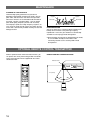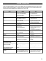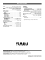
1
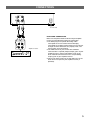
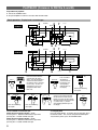
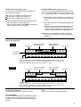
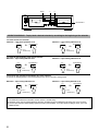
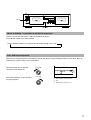
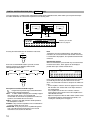
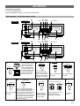
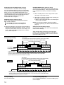
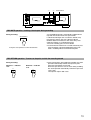
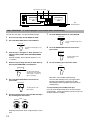
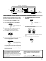
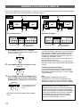
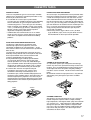
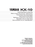
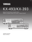
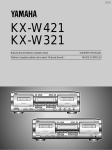
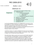
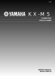
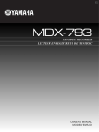
s
KX– W582
–
KX W482
s
DECK A
DECK B
s
DECK A
DECK B
Natural Sound Stereo Cassette Deck
OWNER’S MANUAL
Í
IMPORTANT
Please record the serial number of your unit in the space below.
Model:
Serial No:
The serial number is located on the rear of the unit.
Retain this Owner’s Manual in a safe place for future reference.
1
Thank you for purchasing the YAMAHA stereo cassette deck.
SAFETY INSTRUCTIONS
7 Wall or Ceiling Mounting — The appliance should be
CAUTION
RISK OF ELECTRIC SHOCK
DO NOT OPEN
CAUTION: TO REDUCE THE RISK OF ELECTRIC
SHOCK, DO NOT REMOVE COVER (OR BACK).
NO USER-SERVICEABLE PARTS INSIDE. REFER
SERVICING TO QUALIFIED SERVICE PERSONNEL.
mounted to a wall or ceiling only as recommended by the
manufacturer.
8 Ventilation — The appliance should be situated so that its
location or position does not interfere with its proper
ventilation. For example, the appliance should not be
situated on a bed, sofa, rug or similar surfaces that may
block the ventilation openings: or placed in a built-in
installation, such as a bookcase or cabinet that may impede
the flow of air through the ventilation openings.
9 Heat — The appliance should be situated away from heat
÷ Explanation of Graphical Symbols
The lightning flash with arrowhead symbol, within an
equilateral triangle, is intended to alert you to the presence of
uninsulated “dangerous voltage” within the product's
enclosure that may be of sufficient magnitude to constitute a
risk of electric shock to persons.
The exclamation point within an equilateral triangle is
intended to alert you to the presence of important operating
and maintenance (servicing) instructions in the literature
accompanying the appliance.
sources such as radiators, stoves, or other appliances that
produce heat.
10 Power Sources — The appliance should be connected
to a power supply only of the type described in the operating
instructions or as marked on the appliance.
11 Power-Cord Protection — Power-supply cords should
be routed so that they are not likely to be walked on or
pinched by items placed upon or against them, paying
attention to receptacles, and the point where they exit from
the appliance.
12 Cleaning — The appliance should be cleaned only as
recommended by the manufacturer.
WARNING
To reduce the risk of fire or electric shock, do not
expose this appliance to rain or moisture.
13 No Use Periods — The power cord of the appliance
should be unplugged from the outlet when left unused for a
long period of time.
14 Object and Liquid Entry — Care should be taken so that
1 Read Instructions — All the safety and operating
instructions should be read before the appliance is operated.
2 Retain Instructions — The safety and operating
instructions should be retained for future reference.
3 Heed Warnings — All warnings on the appliance and in
the operating instructions should be adhered to.
4 Follow Instructions — All operating and other instructions
should be followed.
objects do not fall into and liquids not spilled into the inside
of the appliance.
15 Damage Requiring Service — The appliance should be
serviced by qualified service personnel when:
A. The power-supply cord or the plug has been damaged; or
B. Objects have fallen, or liquid has been spilled into the
appliance; or
C. The appliance has been exposed to rain; or
D. The appliance does not appear to operate normally or
exhibits a marked change in performance; or
E. The appliance has been dropped, or the cabinet
damaged.
5 Water and Moisture — The appliance should not be used
near water — for example, near a bathtub, washbowl,
kitchen sink, laundry tub, in a wet basement, or near
swimming pool, etc.
16 Servicing — The user should not attempt to service the
6 Carts and Stands — The appliance should be used only
with a cart or stand that is recommended by the
manufacturer.
17 Grounding or Polarization — The precautions should be
6A An applicance and cart
combination should be moved with
care. Quick stops, excessive force,
and uneven surfaces may cause the
appliance and cart combination to
overturn.
2
appliance beyond those means described in the operating
instructions. All other servicing should be referred to
qualified service personnel.
taken so that the grounding or polarization of an appliance is
not defeated.
CAUTION: READ THIS BEFORE OPERATING
YOUR UNIT.
FCC INFORMATION (U.S.A.)
1.IMPORTANT NOTICE: DO NOT MODIFY THIS UNIT!
This product, when installed as indicated in the
instructions contained in this manual, meets FCC
requirements. Modifications not expressly approved by
Yamaha may void your authority, granted by the FCC,
to use the product.
2.IMPORTANT: When connecting this product to
accessories and/or another product use only high
quality shielded cables. Cables supplied with this
product MUST be used. Follow all installation
instructions. Failure to follow instructions could void
your FCC authorization to use this product in the USA.
3.NOTE: This product has been tested and found to
comply with the requirements listed in FCC
Regulations, Part 15 for Class "A" digital devices.
Compliance with these requirements provides a
reasonable level of assurance that your use of this
product, in a commercial environment, will not result in
harmful interference with other electronic devices.
However, operation of this product in a residential area
is likely to cause interference in some form. In this
case you, the user, bear the responsibility of correcting
this condition.
This product generates/uses radio frequencies and, if
not installed and used according to the instructions
found in the users manual, may cause interference
harmful to the operation of other electronic devices.
Compliance with FCC regulations does not guarantee
that interference will not occur in all installations. If this
product is found to be the source of interference, which
can be determined by turning the product "OFF" and
"ON", please try to eliminate the problem using one of
the following measures:
Relocate either the product generating the interference
of the device that is being affected by the interference.
Utilize power outlets that are on different branch (circuit
breaker or fuse) circuits or install AC line filter/s.
1. This unit is a sophisticated stereo cassette deck. To
ensure proper operation for the best possible
performance, please read this manual carefully.
2. Choose the installation location of your unit carefully.
Avoid placing it in direct sunlight or close to source of
heat. Also avoid locations subject to vibration and
excessive dust, heat, cold or moisture. Keep it away
from sources of hum such as transformers or motors.
3. Do not open the cabinet as this may result in damage
to the deck or electrical shock. If a foreign object
should get into the deck, contact your local dealer.
4. Do not apply excessive force when operating switches
and knobs.
5. When moving the deck, be sure to first pull out the
power plug and remove all cords connecting the deck
to other equipment.
6. Do not attempt to clean this unit with chemical
solvents as this may damage the finish. Use a clean,
dry cloth.
7. Never allow metallic items (e.g. screwdrivers, tools,
etc.) to come near the record/playback head
assembly. Doing so may not only scratch or damage
the head’s mirror-smooth finish, it may also change
the magnetic characteristics of the heads, causing a
deterioration in reproduction quality.
8. Although the record/playback head used in this unit is
a high quality head with outstanding reproduction
characteristics, it can become dirty through the use of
old tapes or from dust accumulation over time.
This can have a serious effect on reproduction quality.
Clean the heads regularly with one of the commonly
available head cleaners or with cleaning solutions as
explained later in this manual.
In the case of radio or TV interference, relocate/reorient
the antenna. If the antenna lead-in is 300 ohm ribbon
lead, change the lead-in to coaxial type cable.
9. Be sure to read the “Troubleshooting” section of this
If these corrective measures do not produce
satisfactory results, please contact your local retailer
that is authorized to distribute this type of product. If
you cannot locate the appropriate retailer, please
contact Yamaha Electronics Corp., U.S.A. 6600
Orangethorpe Ave, Buena Park, CA90620
10. Unplug the power cord from the wall outlet if the unit
The above statements apply ONLY to those products
distributed by Yamaha Corporation of America or its
subsidiaries.
We Want You Listening For A Lifetime
YAMAHA and the Electronic Industries Association's
Consumer Electronics Group want you to get the most out of
your equipment by playing it at a safe level.
One that lets the sound come through loud
and clear without annoying blaring or
distortion – and, most importantly, without
affecting your sensitive hearing. Since
hearing damage from loud sounds is often
undetectable until it is too late, YAMAHA and
We
the Electronic Industries Association's
Want You
Consumer Electronics Group recommend
LISTENING
For A Lifetime
you avoid prolonged exposure to excessive
volume levels.
manual for advice on common operating errors before
concluding that your unit is faulty.
is not to be used for an extended period of time. To
disconnect the cord, pull it out by grasping the plug.
Never pull the cord itself.
11. Keep this manual in a safe place for future reference.
12. Voltage Selector (General model only)
The voltage selector on the rear panel of this unit
must be set for your local mains voltage BEFORE
plugging in the AC mains supply.
Please check the copyright laws in your country to
record from records, compact discs, radio, etc.
Recording of copyright material may infringe copyright
laws.
3
TABLE OF CONTENTS
FEATURES ......................................................................... 4
CONNECTIONS .................................................................. 5
PLAYBACK ......................................................................... 6
Basic operation ................................................................ 6
SELECTION SEARCH .................................................... 8
RELAY PLAYBACK ......................................................... 9
PLAY TRIM control adjustment ....................................... 9
DIGITAL SUPER SURROUND (DSS)
(KX-W582 only) ............................................................. 10
RECORDING .................................................................... 11
Basic operation .............................................................. 11
REC MUTE operation .................................................... 13
REC RETURN operation ............................................... 13
DUAL RECORDING ...................................................... 14
RELAY RECORDING .................................................... 15
DUBBING .......................................................................... 16
CASSETTE TAPES .......................................................... 17
MAINTENANCE ................................................................ 18
OPTIONAL REMOTE CONTROL TRANSMITTER .......... 18
TROUBLESHOOTING ...................................................... 19
SPECIFICATIONS ............................................... Back cover
FEATURES
÷ High Quality Hard Permalloy Recording/Playback Head in
Both Decks
÷ Secure Holding Damper Cassette Stabilizer allows you to
reduce unwanted vibration and modulation noise (KXW582 only)
÷ Dolby HX Pro Dynamic Bias Servo
÷ Dolby B/C Noise Reduction
÷ Digital Super Surround (DSS) Function enables you to
create an excellent audio sound field, applicable also for
recording (KX-W582 only)
÷ Play Trim Control for improved playback compatibility with
other decks
÷ Auto Tape Selector
4
÷ Dual Recording allows you to make the same recording on
both decks simultaneously
÷ Relay Playback from DECK A to DECK B
÷ Relay Recording from DECK A to DECK B
÷ Selection Search
÷ Recording Mute Function
÷ Rec Return Operation
÷ Easy Dubbing Operation at Selectable Speed (Normal/
High)
÷ Peak Level Meters with Peak Hold Function
÷ Remote Control Capability with Optional Remote Control
Transmitter
CONNECTIONS
L
R
LINE IN
REC
LINE OUT
PLAY
To an AC outlet
REC OUT
TAPE PB
L
R
Amplifier or receiver
REAR PANEL CONNECTIONS
Make sure that power to both the deck and your amplifier/
receiver is turned off before making any connections.
÷ The White plug on the paired connecting cables
corresponds to the Left channel and the Red plug
corresponds to the Right channel. Make sure that the left
and right channel connections are properly made, and
that the plugs are inserted firmly.
÷ The LINE OUT/PLAY jacks on the deck should be
connected to the Tape PB (Playback/Input) jacks on your
amplifier/receiver, and the LINE IN/REC jacks on the
deck should be connected to the Rec Out (Recording/
Output) jacks on your amplifier/receiver.
÷ Connect the power cord to an AC wall outlet or to an AC
outlet on the rear panel of your amplifier/receiver (if
provided).
5
PLAYBACK (Common to DECKs A and B)
Preparation for playback
÷ Turn on the POWER switch.
÷ Set your amplifier or receiver to cassette deck function mode.
Basic operation - To play back a cassette tape
POWER = ON
KX-W582
4
2
PHONES
7
!/⁄
RESET
s
DECK A
5
1
POWER = ON
KX-W482
DECK B
4
6 3 STOP
2 7
PHONES
1
!/⁄
RESET
s
DECK A
5
1
4
5
DOLBY NR
B
+
1
OFF
C
=
Refer to the following
description.
“
+
MODE
”
6
RELAY
=
Refer to the following
description.
To fast forward or rewind the tape
When the tape running indicator # is lit:
Pressing the ⁄ button fast forwards the tape while
pressing the ! button rewinds the tape.
When the tape running indicator @ is lit:
Pressing the ! button fast forwards the tape while
pressing the ⁄ button rewinds the tape.
6
6
Insert the cassette with the
exposed tape side facing
down. (The side facing you is
called the forward side and
the opposite side is called the
reverse side.) To close the
compartment, push in the
compartment door until it
locks shut.
EJECT
DECK B
STOP
1
2
DIRECTION
A
B
3
DECK A/B
Press the DECK
A/B button to
select the deck to
be operated. The
corresponding
indicator lights on
the display.
KX-W582
only
DSS
DSS MODE
Refer to the following
description.
Select the tape running direction
for DECK A or B. Each time this
button is pressed, the tape running
direction changes between forward
(#) and reverse (@), and the
corresponding indicator lights on
the display.
7
PLAY
To stop playback
Press the STOP button. To remove the cassette tape, press
the EJECT button. The cassette compartment door opens.
To turn off the power, press the POWER button.
DOLBY NR selector setting (in step 4)
Be sure to set the DOLBY NR selector according to the
system used for recording.
REVERSE MODE selector setting (in step 5)
The auto reverse function allows the tape running direction
to be reversed automatically. Select an auto reverse mode
(”), manual reverse mode (“) or RELAY playback mode.
OFF: For a tape recorded with DOLBY NR OFF.
B: For a tape recorded with DOLBY B NR.
C: For a tape recorded with DOLBY C NR.
“: When playback or fast forwarding (or rewinding) of one
side of a tape is finished, the deck stops at the end of
the tape.
* Dolby noise reduction manufactured under license from
Dolby Laboratories Licensing Corporation.
“DOLBY” and the double-D symbol
are trademarks of
Dolby Laboratories Licensing Corporation.
”: Both sides of the tape are repeatedly played back (up
to 8 times).
÷ When the tape is fast forwarded to the end of a side,
playback automatically starts from the other side.
When the tape is rewound to the beginning of a side,
playback automatically starts from the beginning.
RELAY: Cassette tapes loaded in DECKs A and B are
played back sequentially. (See “RELAY PLAYBACK”
on page 9.)
Display during playback
KX-W582
Tape counter
Tape running direction
indicator (DECK A)
Tape running direction
indicator (DECK B)
¤A‹
SYNCHRO
DUB NORM HIGH
HALL DISCO CHURCH
REC
DSS PRESET
PROGRAM indicators
L
dB
R
– 30
20
15
10
8
6
4
Tape counter
¤B‹
REC
JAZZ CLUB
2
0
2
4
6
+
Peak level meters
Indicate the peaks of the signal levels during recording and playback over a –30 dB to +6 dB
range. There are separate meters for each left and right channel. These level meters have a
peak hold function which holds the peak level for about 1.5 seconds.
KX-W482
Tape counter
Tape running direction
indicator (DECK A)
¤A‹
REC
L
dB
R
– 30
20
15
10
8
Tape running direction
indicator (DECK B)
SYNCHRO
DUB NORM HIGH
6
4
Tape counter
¤B‹
REC
2
0
2
4
6
+
Peak level meters
Indicate the peaks of the signal levels during recording and playback over a –30 dB to +6 dB
range. There are separate meters for each left and right channel. These level meters have a
peak hold function which holds the peak level for about 1.5 seconds.
To adjust the volume level
Use the volume control of the amplifier or receiver.
Note
Never press the EJECT button during playback.
To use headphones
Insert the headphones plug into the PHONES jack. Since
the sound is also heard from the speakers, operate the
amplifier to cut off the sound from the speakers for private
listening.
7
RESET
!
⁄
s
MUTE/SEARCH
DECK A
DECK B
SELECTION SEARCH - To play back a desired selection by searching for the beginning of the selection
To search for the next selection
When the # tape running indicator is lit:
⁄
MUTE/SEARCH
+
When the @ tape running indicator is lit:
!
MUTE/SEARCH
+
Press
simultaneously.
Press
simultaneously.
To search for the beginning of the current selection
When the # tape running indicator is lit:
!
+
MUTE/SEARCH
When the @ tape running indicator is lit:
⁄
Press
simultaneously.
+
MUTE/SEARCH
Press
simultaneously.
To search for the selection located before the current selection
÷ Operate the following buttons when the beginning of the current selection is being played.
When the # tape running indicator is lit:
!
+
MUTE/SEARCH
Press
simultaneously.
When the @ tape running indicator is lit:
⁄
+
MUTE/SEARCH
Press
simultaneously.
Notes
÷ The blank interval between selections must be at least 4 seconds long.
÷ Selection search may not operate properly with tapes recorded at a low recording level or which have excessive noise.
÷ Use the tape counter to aid in locating a point on a tape (0000 to 9999). To set the counter reading to “0000”, press the
RESET button.
8
s
MODE
DECK A
DECK B
PLAY TRIM
RELAY PLAYBACK - To play DECK A and DECK B sequentially
Load the cassette tapes into DECKs A and B, start playback of DECK A.
Set the MODE selector to the RELAY position.
DECK A (forward side \ reverse side) \ DECK B (forward side \ reverse side)
5
Up to 8 times
PLAY TRIM control adjustment
When the level of high frequencies is too boosted or absent while playing a tape recorded on another cassette deck, adjust the
high frequency response with the PLAY TRIM control.
When high frequencies are too loud,
attenuate the high frequencies.
PLAY TRIM
0
+
10 dB
–
When high frequencies are too soft, boost
the high frequencies.
PLAY TRIM
0
–
100
+
1
2
3
1k
_
1
2
3
10kHz
High frequency sound is too loud.
Flat
High-frequency sound is too soft.
+
9
DIGITAL SUPER SURROUND (DSS) ( KX-W582 only)
This unit incorporates a sophisticated, multi-program Digital Super Surround function, which allows you to expand and shape
the audio sound field, for a theater-like experience in the listening room.
s
¶
DECK A
DECK B
DSS
DSS MODE
∞
¤A‹
SYNCHRO
DUB NORM HIGH
HALL DISCO CHURCH
REC
L
dB
R
– 30
20
15
10
8
6
¤B‹
4
Pressing the DSS button turns on and off the DSS effect.
DSS
Each time the DSS MODE button is pressed, the DSS
program changes in the following order and the
corresponding indicator lights:
3 HALL
3 DISCO
3 CHURCH
REC
Indicates your selection
of the DSS program.
JAZZ CLUB
2
0
2
4
6
+
Note
To playback the tape recorded with this unit applying the
DSS effect, be sure to turn off the DSS function. If the DSS
is activated also for playback, the reproduced sound will be
unnatural.
DSS monitor function
When the DSS button is pressed with any cassette inserted
in neither of the decks, “dSS” appears on the display in
position of the tape counters of both decks.
A‹
3 JAZZ CLUB
‹
HALL
JAZZ CLUB 2
CHURCH 2
DISCO 2
HALL 2
L
dB
R
– 30
20
15
10
8
6
4
2
0
2
4
6
+
DSS MODE
Description of each Sound Field Program
: Programmed to provide largest sound field effects
when listening through headphones.
HALL: A mode suitable for playing live recording of pop or
rock concerts with vocals. The expansion and
reverberation of concert hall are provided even when the
speakers are installed close to each other.
DISCO: Crisp bass and solid, powerful sound reproduces
the atmosphere of a disco.
CHURCH: Long echo time reproduces rich reverberation in
a church. Suitable for vocal music.
JAZZ CLUB: A very rich presence is reproduced together
with a three-dimensional feeling where each musical
instrument asserts itself in the front line.
10
In this state, DSS effect can be applied to the input signal to
the LINE IN jacks from any other source than cassette
decks. The sound with DSS effect is output to the LINE OUT
jacks.
• On the amplifier, select the source to apply the DSS effect
with the REC OUT selector and set the input selector to
the TAPE position.
If the amplifier has no REC OUT selector, select the
source with the input selector and set the amplifier to the
TAPE MONITOR mode.
• Adjust the output level with the REC LEVEL control so that
the reproduced sound is not distorted. For details, see
“Setting the recording level” on page 12.
RECORDING
Preparation for recording
÷ Turn on the POWER switch.
÷ Set your amplifier or receiver to cassette deck function mode.
Basic operation - To record a program source
POWER = ON
KX-W582
4
RESET
2 79
MUTE/SEARCH
s
DECK A
5
1
POWER = ON
KX-W482
DECK B
6
4
RESET
3 8 STOP
2 79
1
MUTE/SEARCH
s
DECK A
5
1
Insert the cassette with the
exposed tape side facing
down. (The side facing
you is called the forward
side and the opposite side
is called the reverse side.)
To close the compartment,
push in the compartment
door until it locks shut.
EJECT
5
“
+
6
MODE
”
1
DIRECTION
A
B
DECK B
6
2
8
1
STOP
3
DECK A/B
KX-W582
4
only
DSS
DOLBY NR
OFF
B
C
DSS MODE
+
Press the DECK A/B
button to select DECK A
or B. The corresponding
indicator for the selected
deck lights on the diplay.
7
Refer to the following
description.
=
Refer to the following
description.
8
9
REC/PAUSE
REC
BALANCE
PLAY
LEVEL
RELAY
1
=
Refer to the following
description.
Select the tape running direction.
(Press the DIRECTION A button for
DECK A and the DIRECTION B
button for DECK B.) Each time one of
these button is pressed, the tape
running direction of the corresponding
deck changes between forward (#)
and reverse (@), and the indicator
lights on the display.
1
2
3
4
3
4
5 R
L 5
The REC indicator
lights on the display.
The deck enters the
rec pause mode.
0
2
4
5
6
3
2
7
8
9
1
0
10
Play the program source to be
recorded and adjust the
recording level and balance.
Recording
starts.
11
REVERSE MODE selector setting (in step 5)
The auto reverse function allows the tape running direction
to be reversed automatically. Select an auto reverse mode
(”), manual reverse mode (“) or RELAY recording
mode.
Digital Super Surround (DSS) setting (in step 3)
The DSS function can be utilized also for recording.
Press the DSS MODE button to turn on the DSS function,
and select one of the DSS programs by pressing the DSS
button so that the corresponding indicator lights up. By
recording with this function, you can enjoy the sources with
your preferred DSS effect even when played back on car
audios or portable headphone stereo systems.
For details on DSS, see page 10.
“: When recording on one side of a tape is finished, the
deck stops at the end of the tape.
”: Both sides of a tape are recorded. After recording, the
deck stops at the end of the tape.
÷ When the tape running direction is set to ™, only the
reverse side is recorded.
DOLBY NR selector setting (in step 4)
Set the DOLBY NR selector according to your purpose.
OFF: No noise reduction.
B: For recording the sources with Dolby B NR.
C: For recording the sources with Dolby C NR.
RELAY: Cassette tapes loaded in DECKs A and B are
recorded sequentially. (See “RELAY RECORDING” on
page 15.)
÷ Dolby noise reduction is an extremely effective method of
reducing undesirable background hiss on tapes. This unit
incorporates both Dolby B NR and the newer Dolby C NR
system. Dolby C NR is approximately twice as effective
as the earlier Dolby B NR.
Display during recording
Setting the recording level (in step 8)
Play the loudest passage of the source to be recorded and
watch the meter readings.
Adjust the REC LEVEL control so that the highest peak
reaches +4 of the optimum recording level. Normally, it is
best to adjust the BALANCE control such that the left and
right meter readings are even.
Tape counter
Use the tape counter to aid in locating a point on a tape (0000 to 9999).
To set the counter reading to “0000”, press the RESET button.
KX-W582
Tape running direction indicator
REC indicator
REC indicator
¤A‹
SYNCHRO
DUB NORM HIGH
HALL DISCO CHURCH
REC
DSS PRESET
PROGRAM indicators
L
dB
R
– 30
20
15
10
8
6
4
¤B‹
REC
JAZZ CLUB
2
0
2
4
6
+
Peak level meters
Indicate the peaks of the signal levels during recording and playback over a –30 dB to +6 dB range.
There are separate meters for each left and right channel. These level meters have a peak hold
function which holds the peak level for about 1.5 seconds.
Tape counter
Use the tape counter to aid in locating a point on a tape (0000 to 9999).
To set the counter reading to “0000”, press the RESET button.
KX-W482
REC indicator
Tape running direction indicator
REC indicator
¤A‹
REC
L
dB
R
– 30
20
15
10
8
SYNCHRO
DUB NORM HIGH
6
4
¤B‹
REC
2
0
2
4
6
+
Peak level meters
Indicate the peaks of the signal levels during recording and playback over a –30 dB to +6 dB range.
There are separate meters for each left and right channel. These level meters have a peak hold function
which holds the peak level for about 1.5 seconds.
To stop recording:
Press the STOP button.
12
To stop recording temporarily:
Press the REC/PAUSE button. To resume recording, press
the PLAY button.
!
⁄
MUTE/SEARCH
s
DECK A
DECK B
REC MUTE operation - Inserting a blank space during recording
During recording:
MUTE/SEARCH
During Rec mute operation, the REC indicator blinks.
A 4-second blank interval is automatically recorded on the
tape and then the deck enters Rec pause mode.
If a blank interval longer than 4 seconds is desired, keep
pressing for as long as you want. When the MUTE/
SEARCH button is released, the deck enters Rec pause
mode after making a 4-second blank interval.
To resume recording, press the PLAY button.
÷ If a blank interval shorter than 4 seconds is desired, press
the PLAY button at the desired point during Rec mute
mode. Recording will be resumed from that point.
REC RETURN operation - To return to the point at which the recording started
During recording:
When the # indicator
is lit:
!
When the @ indicator
is lit:
⁄
÷ If the PLAY button is pressed during recording, Rec return
operation automatically rewinds the tape to the point
where the PLAY button was pressed.
When the tape counter is reset to “0000” during recording,
Rec return operation automatically rewinds the tape to the
“0000” point.
The tape then stops in both cases.
13
REC/PAUSE
DECK A/B
PLAY
s
DECK A
DECK B
REC
BALANCE/LEVEL
DUAL RECORDING - To record a program source on both decks simultaneously
To make the same tapes, use tapes of identical length.
1
Insert cassette tapes in both DECKs A and B.
2
Press the DECK A/B button to select DECK A.
7
Press the DECK A/B button to select DECK B.
DECK A/B
The DECK B indicator lights on the
display.
DECK A/B
The DECK A indicator lights on the
display.
8
Press the REC/PAUSE button to enter the rec
pause mode.
REC/PAUSE
3
4
Perform steps 3 through 5 of “Basic operation” to
adjust the DSS, DOLBY NR and REVERSE MODE
settings.
For dual recording, Set the MODE selector to “ or
” position.
Select the tape running direction for both decks by
pressing the DIRECTION A and B buttons.
The REC indicator of the
DECK B lights.
9
To start recording, press the PLAY button.
PLAY
DIRECTION
A
B
The tape running direction
indicator of the corresponding
deck (forward # or reverse @)
lights on the display.
5
Press the REC/PAUSE button to enter the rec
pause mode.
REC/PAUSE
The REC indicator of the
DECK A lights.
6
Play the program source to be recorded and adjust
the recording level and balance.
REC
BALANCE
1
0
1
2
2
3
4
3
4
5 R
L 5
LEVEL
4
5
6
3
2
7
8
9
1
0
10
Recording level for both decks is adjusted to the same
level.
14
Both decks start recording simultaneously.
Once the dual recording starts, pressing the REC/
PAUSE or STOP button or perfoming the REC
RETURN/REC MUTE operation affects both decks
simultaneously.
To stop recording in the middle of the tape
Press the STOP button of both decks on the front panel
simultaneously. If the STOP button of one deck is pressed,
the other continues recording.
REC/PAUSE
DECK A/B
PLAY
s
MODE
DECK A
DECK B
REC
BALANCE/LEVEL
RELAY RECORDING - To record a program source sequentially on DECK A and DECK B
Recording can be made sequentially on DECKs A and B.
Start the relay recording always from the cassette in DECK
A.
1
Insert cassette tapes in both DECKs A and B.
2
Press the DECK A/B button to select DECK A.
6
Press the REC/PAUSE button to enter the rec
pause mode.
REC/PAUSE
The REC indicator of the
DECK A lights.
DECK A/B
The DECK A indicator lights on the
display.
3
Perform steps 3 and 4 of “Basic operation” to
adjust the DSS and DOLBY NR settings.
4
Set the MODE selector to RELAY position.
7
Play the program source to be recorded and adjust
the recording level and balance.
1
MODE
”
“
RELAY
=
0
1
2
2
3
4
3
4
5 R
L 5
5
REC
BALANCE
LEVEL
4
5
6
3
2
7
8
9
1
0
10
Recording level for both decks is adjusted to the same
level.
8
Select the tape running direction for both decks by
pressing the DIRECTION A and B buttons.
To start recording, press the PLAY button.
PLAY
DIRECTION
A
B
The tape running direction
indicator of the corresponding
deck (forward # or reverse @)
lights on the display.
To record on both sides of the tapes, rewind them to
the beginning of the forward side and select forward
(#) with the DIRECTION A and B buttons respectively.
When reverse (@) is selected, the source is recorded
only on the reverse side.
DOLBY HX PRO DYNAMIC BIAS SERVO SYSTEM
This unit incorporates the Dolby HX Pro system which
automatically controls the effective bias to reduce
distortion and noise, improving high frequency response
during recording. Tapes recorded with this system retain
the same high quality even when played back on any
other cassette deck.
Dolby noise reduction and HX Pro headroom extension
manufactured under license from Dolby Laboratories
Licensing Corporation, HX Pro originated by Bang &
Olufsen.
“DOLBY”, the double-D symbol
and “HX PRO” are
trademarks of Dolby Laboratories Licensing Corporation.
15
DUBBING (From DECK B to DECK A)
You can make dubbing from DECK B to DECK A. Open the cassette compartments by pressing the EJECT buttons and load a
blank cassette tape in DECK A and the original cassette tape in DECK B.
2
KX-W582
s
s
DECK A
DECK B
1
3
DECK A
SYNCHRO
DUB NORM HIGH
HALL DISCO CHURCH
REC
20
15
10
8
6
Lights during dubbing.
1
+
2
4
¤A‹
¤B‹
MODE
”
REC
REC
2
0
2
4
6
+
NORM or HIGH indicator
lights during dubbing.
RELAY
=
Set the DIRECTION buttons for DECKs A and B.
DIRECTION
A
3
B
Set the DUBBING speed to either NORM (normal
speed) or HIGH (twice the normal speed) with the
DUBBING buttons*. Dubbing starts automatically.
DUBBING
NORM
SYNCHRO
DUB NORM HIGH
¤B‹
REC
L
dB
R
– 30
20
15
10
Lights during dubbing.
8
6
4
2
0
2
4
6
+
NORM or HIGH indicator
lights during dubbing.
To stop dubbing
Press the STOP button. (When DECK A is selected with the
DECK A/B button, both decks stop simultaneously and the
dubbing mode is cancelled. When DECK B is selected,
DECK B stops immediately and then DECK A stops after
recording a 4-second blank section.)
When the tape in DECK A reaches its end, DECK A and
DECK B stop at the same time.
When the tape in DECK B reaches its end, DECK B stops
and DECK A stops after providing a blank section of about 4
seconds.
Available operations while dubbing
The Rec Return function can be carried out on DECK A.
Refer to “REC RETURN operation” on the previous page.
While dubbing, the buttons other than ! and ⁄ buttons
cannot be operated.
Note
During dubbing, the Dolby NR and the DSS are
automatically set to OFF and the recorded tape can be
dubbed as it is. (When the tape to be dubbed is recorded
with Dolby NR and/or DSS, these effects are also dubbed.)
HIGH
The corresponding NORM or
HIGH indicator lights on the
display.
* Higher quality sound will be obtained with the NORM
setting.
16
STOP
JAZZ CLUB
Set the MODE selector to “ or ” position.
Setting the MODE selector to RELAY position results in
the same function as to “.
“
3
Display during dubbing
¤A‹
– 30
DECK B
1
STOP
Display during dubbing
L
dB
R
2
KX-W482
Synchronized recording function
When operating this unit in combination with the
YAMAHA CD Player which has SYNCHRO button on its
remote control transmitter, CD Synchronized recording
function can be utilized. This function is operated with the
remote control transmitter of the CD Player. (Regarding
the operation, refer to the manual of the CD Player.)
The SYNCHRO indicator lights when the SYNCHRO
button of the remote controller is pressed.
CASSETTE TAPES
CASSETTE TAPES
There are many different types of cassette tapes available.
However, they all conform to standard specifications so any
brand may be used with the deck.
÷ Classification of Cassette Tapes by Formulation:
Cassette tapes are available in four basic types depending
on their formulation, or type of magnetic material and
manufacturing process. These four types are commonly
known as Normal (Type I/NORM), Chrome (Type II/HIGH
<CrO2>), Ferrichrome (Type III/FeCr), and Metal (Type IV/
METAL), and they each require specific tape deck
adjustments for optimum performance.
* YAMAHA does not recommend the use of 120 minute
length cassettes since the extreme thinness of the tape
makes them susceptible to mechanical and recording
problems.
AUTO TAPE SELECTOR DETECTION SLOTS
The deck has a built-in Auto Tape Selector which
automatically adjusts for the proper bias, level and
equalization according to the tape formulation — all you
have to do is to load a cassette and the Auto Tape Selector
does the rest.
The Auto Tape Selector determines which type of tape is
loaded by sensing detector slots in the top of the tape shell.
Each tape formulation has its own characteristic hole
markings standardized by the tape industry.
÷ Early model Metal (Type IV/Metal) tape formulation
cassette shells do not have the slots for Auto Tape
Selector operation. As a result, early model Metal type
tapes recorded on another deck will be played back with
the deck at the Chrome (Type II/HIGH <CrO2>) settings.
YAMAHA does not recommend using this kind of tape.
÷ The deck does not have the required setting for
Ferrichrome (Type III/FeCr) tape, since this tape
formulation is not widely used. Should you use a
Ferrichrome tape, it will be recorded and played back at
the Normal (Type I/NORM) settings, which will result in an
unnatural high frequency emphasis. This effect may be
compensated for somewhat by adjusting the PLAY TRIM
control and/or the tone controls of your amplifier/receiver
during playback.
TYPE II
Detector slots
PROTECTING YOUR RECORDINGS
All cassette tapes are provided with erasure protection holes
to prevent accidental erasure of recorded contents. There is
a small tab covering the hole on each side of the cassette,
and it should be broken off after recording the tape. Without
this tab covering the hole, it is impossible to record onto that
tape. Thus, you can safely protect a recording for as long as
you wish without fear of accidental erasure. Should you wish
to use a cassette tape protected in this way for recording,
simply covering the hole with adhesive tape will permit
erasure and re-recording.
÷ When using Chrome (Type II/HIGH <CrO2>) or Metal
(Type IV/METAL) tapes, make sure you do not cover the
hole intended for the Auto Tape Selector operation.
TAKING UP SLACK IN THE TAPE
As a precaution against tape entanglement and damage,
remove any slack in the tape before inserting cassettes into
the deck. This is accomplished by inserting a pencil, pen or
similar object into one of the spools and gently winding it
until all the slack is removed. You do not have to wind it too
tightly.
Be careful not to touch the tape part itself. It is very delicate
and touching it may damage the tape and its recorded
contents.
TYPE IV
Detector slots
STORING CASSETTES
After putting a cassette tape back into its case, store it in a
location away from exposure to direct sunlight, humidity,
high temperatures, and magnetic fields (away from television
sets, speakers, etc.). High temperatures and humidity will
damage the tape itself, while exposure to magnetic fields
may cause a loss of recorded material. Avoid touching the
tape surface with your fingers, since dirt or finger oil will
contaminate the deck’s heads.
17
MAINTENANCE
CLEANING OF THE TAPE PATH
Continued high quality performance of your deck is
dependent upon periodic cleaning of the heads, capstan,
pinch roller, and all surfaces over which the tape travels.
Normal use will cause an accumulation of dirt and dust on
the heads, capstans, and pinch rollers. This can lead to
poor sound quality, drop outs (intervals with no sound),
unsteady tape speed, loss of high frequency response, etc.
Thus, clean the heads and all surfaces over which the tape
travels with a commercially available cleaning cassette and
fluid type cleaner.
Heads
Capstan
Capstan
Pinch roller
Pinch roller
DEMAGNETIZATION
After 20-30 hours of use, enough residual magnetism will
build up on the heads to cause poor high frequency
reproduction. At this time you should use a commercially
available cassette tape-type head demagnetizer.
÷ When cleaning the tape path or demagnetizing the heads,
be sure to follow carefully the instructions of the
concerning materials such as cleaning fluid or head
demagnetizer.
OPTIONAL REMOTE CONTROL TRANSMITTER
With the optional remote control transmitter RS-KX1, you
can operate this unit at your listening position. For details,
refer to the instruction manual supplied with the remote
control transmitter.
RESET
REMOTE CONTROL OPERATION RANGE
Remote sensor
MEMORY
COUNTER
REMAIN
TAPE
DUBBING
¤
‹
INTRO SCAN
7 m (23 feet)
⁄
!
SEARCH
DECK A/B
DIR A
DIR B
MONITOR
!
PLAY
⁄
STOP
REC MUTE
REC/PAUSE
s
REMOTE
CONTROL
TRANSMITTER
18
30°
30°
TROUBLESHOOTING
If your cassette deck fails to operate normally, check the following table. It lists common operating errors and simple measures
which you can take to correct the problem. If it cannot be corrected, or the symptom is not listed, disconnect the deck’s power
cord and contact your local YAMAHA dealer or authorized service center for help.
Cause
Fault
Cure
Tape doesn’t move in recording or playback.
÷ Power plug is not properly plugged in.
÷ Cassette shell is warped or damaged.
÷ Reinsert plug properly.
÷ Do not play damaged tapes.
REC/PAUSE button fails to function.
÷ No cassette tape loaded.
÷ Protective tabs are broken off.
÷ Load a cassette tape.
÷ Change tape or cover protective hole with
adhesive tape.
Sounds become faint and sometimes
inaudible.
÷ Head is dirty.
÷ Head is magnetized.
÷ Tape is damaged or of poor quality.
÷ Clean head.
÷ Demagnetize head using head demagnetizer.
÷ Change to a different tape.
Recorded sound is distorted.
÷ Tape is bad (stretched, deformed, etc.).
÷ Cassette shell is warped.
÷ Replace with a fresh tape.
÷ A warped cassette shell cannot be fixed.
Replace with another tape and test.
÷ Check input level with signal level meter and
use lower rec level when recording.
÷ Recording level is too high.
Tape is playing back, but no sound is heard.
÷ Faulty connection between deck and stereo
amplifier/receiver.
÷ Check and secure connections.
Excessive noise.
÷
÷
÷
÷
÷
÷
÷
÷
Head is dirty.
Head is magnetized.
Worn out or poor quality tape.
Connection(s) improperly made.
÷ Affected by external electrical noise.
÷ Tape is wound unevenly.
÷ Clean capstan and pinch roller, or change to
better tape.
÷ Rewind tape.
Tape stops in the middle of recording or
playback.
÷ Slack tape, or tape spillage wound around
capstan.
÷ Insert pencil in hole in cassette shell and turn
to take up slack.
Fails to record.
÷ REC LEVEL control is set to too low.
÷ Protective tabs are broken off.
÷ Adjust REC LEVEL control.
÷ Change tape or cover protective hole with
adhesive tape.
Search does not operate correctly.
÷ Blank section is too short.
÷ Blank sections must be at least 4 seconds
long.
÷ No remedy
÷ No remedy
Excessive wow (wavering of the sound).
÷ Dirty capstan, pinch roller, etc., or poor tape.
Clean head.
Demagnetize head with head demagnetizer.
Change to better tape.
Check input and output connections and
reinsert properly.
÷ Move deck away from electrical appliances
(TV, fluorescent light, electric blanket, etc.).
÷ Recorded section has low-level portions.
÷ Conversation, etc. has been recorded.
High frequencies in the playback sound are
emphasized and unpleasant to listen to, and
noise level (hiss) is also high.
÷ Dolby NR-recorded tape is played back in OFF
position.
÷ Play back in appropriate Dolby NR position.
Playback sound is muffled and high
frequencies are inaudible.
÷ Normally-recorded tape is played back in Dolby
NR.
÷ Heads are dirty.
÷ Heads are magnetized.
÷ Play back in OFF position.
When playing back tapes recorded on other
decks, meter deflections are greater
(smaller) than when recorded.
÷ Basic levels are different for different cassette
decks.
÷ This is not a fault.
The remote control transmitter cannot be
operated.
÷ The batteries are exhausted.
÷ The remote control transmitter is operated from
an incorrect distance or angle.
÷ The remote control sensor is lighted strongly.
÷ Replace batteries.
÷ Operate it from less than 7 meters (about 23
ft.) and 30°.
÷ Place the unit away from the strong light.
÷ Clean heads and carry out demagnetization
with head demagnetizer.
19
SPECIFICATIONS
Type ..................................... Auto reverse 4-track, 2-channel
recording and playback stereo double cassette deck
Motors ......................................... DC servo motor x 2 (main)
Heads .................... Recording/playback: Hard Permalloy x 2
Erase: Double-gap Ferrite x 2
Rapid Transport .......................................... 100 sec. (C-60)
Wow and Flutter
WRMS ..................................................................... 0.08%
W.Peak .................................................................. ±0.15%
Signal-to-Noise Ratio
(Dolby NR off) ......................................................... 58 dB
(Dolby B NR on) ...................................................... 66 dB
(Dolby C NR on) ...................................................... 74 dB
Frequency Response (–20 dB)
Type I/Normal ................................ 20 ~ 17,000 Hz ±3 dB
Type II/High (CrO2) ...................... 20 ~ 18,000 Hz ±3 dB
Type IV/Metal ................................. 20 ~ 20,000 Hz ±3 dB
Harmonic Distortion ..................................... less than 0.8%
Input Sensitivity/Impedance
Line ..................................................... 100 mV/40 k-ohms
Output Level
Line .................................................... 570 mV/1.8 k-ohms
Phones .................................................... 0.23 mV/8 ohms
Channel Separation (1 kHz) ...................... more than 40 dB
Crosstalk (125 Hz) ..................................... more than 55 dB
GENERAL
Power Supply
U.S.A. and Canada model .......................... 120 V, 60 Hz
Europe model .............................................. 230 V, 50 Hz
U.K. model and Australia model ............... 240 V, 50 Hz
General model ................... 110/120/220/240 V, 50/60 Hz
Power Consumption 19 W/9 W (POWER OFF) (KX-W582)
17 W/7 W (POWER OFF) (KX-W482)
Dimensions (W x H x D) ...................... 435 x 126 x 280 mm
(17-1/8" x 4-15/16" x 11")
Weight ................................ 5.1 kg (11 lbs. 4 oz.) (KX-W582)
5.0 kg (11 lbs.) (KX-W482)
Accessory
Audio cord ............................................................... 1 pair
* Specifications subject to change without notice.
s
YAMAHA
YAMAHA
YAMAHA
YAMAHA
YAMAHA
YAMAHA
YAMAHA
ELECTRONICS CORPORATION, USA 6660 ORANGETHORPE AVE., BUENA PARK, CALIF. 90620, U.S.A.
CANADA MUSIC LTD. 135 MILNER AVE., SCARBOROUGH, ONTARIO M1S 3R1, CANADA
ELECTRONIK EUROPA G.m.b.H. SIEMENSSTR, 22-34, D-2084 RELLINGEN, BEI HAMBURG, F.R. OF GERMANY
ELECTRONIQUE FRANCE S.A. 17 RUE DES CAMPANULES, LOGNES 77321 MARNE LA VALLEE CEDEX 2 FRANCE
ELECTRONICS (UK) LTD. YAMAHA HOUSE, 200 RICKMANSWORTH ROAD WATFORD, HERTS WD1 7JS, ENGLAND
SCANDINAVIA A.B. J A WETTERGRENS GATA 1, BOX 30053, 400 43 VASTRA FRÖLUNDA, SWEDEN
MUSIC AUSTRALIA PTY, LTD. 17-33 MARKET ST., SOUTH MELBOURNE, 3205 VIC., AUSTRALIA
ß
20