1
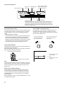
ENGLISH
s KX-10
Natural Sound Stereo Cassette Deck
Platine à cassette stéréo de la série “Natural Sound”
“Natural Sound” Stereo-Kassettengerät
Natural Sound stereokassettdäck
Registratore a cassette stereo a suono naturale
Magnetófono estéreo de sonido natural
Stereo-cassettedeck voor een “natuurlijk geluid”
OWNER’S MANUAL
MODE D’EMPLOI
BEDIENUNGSANLEITUNG
BRUKSANVISNING
MANUALE DI ISTRUZIONI
MANUAL DE INSTRUCCIONES
GEBRUIKSAANWIJZING
1
Thank you for purchasing the YAMAHA KX-10 stereo cassette deck.
CAUTION: READ THIS BEFORE OPERATING YOUR UNIT.
1. This unit is a sophisticated stereo cassette deck. To
ensure proper operation for the best possible
performance, please read this manual carefully.
2. Choose the installation location of your unit carefully.
Avoid placing it in direct sunlight or close to source of
heat. Also avoid locations subject to vibration and
excessive dust, heat, cold or moisture. Keep it away
from sources of hum such as transformers or motors.
3. Do not open the cabinet as this may result in damage
to the deck or electrical shock. If a foreign object
should get into the deck, contact your local dealer.
4. When removing the power plug from the wall outlet,
always pull directly on the plug; never pull the cord
itself.
5. Do not apply excessive force when operating switches
WARNING
TO REDUCE THE RISK OF FIRE OR ELECTRIC
SHOCK, DO NOT EXPOSE THIS APPLIANCE TO
RAIN OR MOISTURE.
For U.K. customers
If the socket outlets in the home are not suitable for the plug
supplied with this appliance, it should be cut off and an
appropriate 3 pin plug fitted. For details, refer to the
instructions described below.
Note: The plug severed from the mains lead must be
destroyed, as a plug with bared flexible cord is hazardous if
engaged in a live socket outlet.
Special Instructions for U.K. Model
and knobs.
IMPORTANT
6. When moving the deck, be sure to first pull out the
power plug and remove all cords connecting the deck
to other equipments.
7. Do not attempt to clean this unit with chemical solvents
as this may damage the finish. Use a clean, dry cloth.
8. Never allow metallic items (e.g. screwdrivers, tools,
etc.) to come near the record/playback head assembly.
Doing so may not only scratch or damage the head’s
mirror-smooth finish, but also change the magnetic
characteristics of the heads, causing a deterioration in
reproduction quality.
9. Although the record/playback head used in this unit is
a high quality head with outstanding reproduction
characteristics, it can become dirty through the use of
old tapes or from dust accumulation over time.
This can have a serious effect on reproduction quality.
Clean the heads regularly with one of the commonly
available head cleaners or with cleaning solutions as
explained later in this manual.
10. Be sure to read the “Troubleshooting” section of this
manual for advice on common operating errors before
concluding that your unit is faulty.
11. Keep this manual in a safe place for future reference.
12. Voltage Selector (General Model only)
The voltage selector on the rear panel of this unit
must be set for your local mains voltage BEFORE
plugging in the AC mains supply.
Please check the copyright laws in your country to
record from records, compact discs, radio, etc.
Recording of copyright material may infringe copyright
laws.
2
The wires in the mains lead are coloured in
accordance with the following code:
Blue: NEUTRAL
Brown: LIVE
As the colours of the wires in the mains lead of this
apparatus may not correspond with the coloured
markings indentifying the terminals in your plug,
proceed as follows. The wire which is coloured BLUE
must be connected the terminal which is marked with
the letter N or coloured BLACK. The wire which is
coloured BROWN must be connected to the terminals
which is marked with the letter L or coloured RED.
Making sure that neither core is connected to the earth
terminal of the three pin plug.
Special Instructions for Canada Model
THIS DIGITAL APPARATUS DOES NOT EXCEED
THE “CLASS B” LIMITS FOR RADIO NOISE
EMISSIONS FROM DIGITAL APPARATUS SET OUT
IN THE RADIO INTERFERENCE REGULATION OF
THE CANADIAN DEPARTMENT OF
COMMUNICATIONS.
CAUTION: TO PREVENT ELECTRIC SHOCK, MATCH
WIDE BLADE OF PLUG TO WIDE SLOT AND FULLY
INSERT.
This unit is not disconnected from the AC power source
as long as it is connected to the wall outlet, even if this
unit itself is turned off. This state is called the standby
mode. In this state, this unit is designed to consume a
very small quantity of power.
FEATURES ......................................................................... 3
CONNECTIONS ................................................................. 4
PLAYBACK ......................................................................... 5
SELECTION SEARCH .................................................... 7
RECORDING ...................................................................... 8
VARIOUS FUNCTIONS HELPFUL FOR HIGH QUALITY
RECORDING .................................................................. 10
REC MUTE OPERATION ............................................. 11
REC RETURN OPERATION ........................................ 11
0-RETURN OPERATION ............................................. 11
CASSETTE TAPES ..........................................................
MAINTENANCE ...............................................................
OPTIONAL REMOTE CONTROL TRANSMITTER .........
TROUBLESHOOTING .....................................................
SPECIFICATIONS ...........................................................
12
13
13
14
15
FEATURES
¶ 3-Head Configuration
¶ Dolby HX Pro Dynamic Bias Servo
¶ Dolby B/C Noise Reduction
¶ Auto Tape Tuning improves the quality of recording by
automatically adjusting the recording characteristics
(recording bias and sensitivity) for best result with every
cassette tape
¶ Play Trim Control for Improved Playback Compatibility
with Other Decks
¶ Selection Search
¶ Recording Mute Function
¶ Rec Return/0-Return Function
¶ Integrated System Remote Control Compatibility
Note on transportation
This cassette tray protector protects against shock during
transportation.
Be sure to remove the protector before operating the unit,
and keep it for future use.
Cassette tray protector
3
ENGLISH
TABLE OF CONTENTS
CONNECTIONS
LINE IN LINE OUT
REC
PLAY
4
3
L
L
R
R
To an AC outlet
Amplifier
R
L
TAPE
PB
TAPE
REC
OUT
REAR PANEL CONNECTIONS
Make sure that power to both the deck and your amplifier/
receiver are turned off before making any connection.
¶ The White plug on the paired connecting cables
corresponds to the Left channel and the Red plug
corresponds to the Right channel. Make sure that the left
and right channel connections are properly made, and
that the plugs are inserted firmly.
¶ The LINE OUT/PLAY jacks on the deck should be
connected to the Tape PB (Playback/Input) jacks on your
amplifier/receiver, and the LINE IN/REC jacks on the
deck should be connected to the REC OUT (Recording/
Output) jacks on your amplifier/receiver.
When using the amplifier AX-10, connect them referring
to the numbers 3 and 4 on both units.
4
¶ Connect the power cord to an AC wall outlet or to an AC
outlet on the rear panel of your amplifier/receiver (if
provided).
ENGLISH
PLAYBACK
Preparation for playback
¶ Press the STANDBY/ON switch to turn on the power.
¶ Set your amplifier to cassette deck function mode.
1
! ⁄
SOURCE
B/
REC
TAPE
L
dB
R
30
20
15
10
8
6
I/NORM II/HIGH IV/METAL
TAPE TUNING
4
C indicators
Ÿ 0
ŸBC
2
MPX FILTER
4
6
STANDBY/ON
switch
2 COUNTER
RESET
1
MONITOR
7 STOP PLAY TRIM
2
)
3
3
DOLBY NR
‹ PLAY
OFF/ŸB/
ŸC/MPX
Place the cassette on the cassette tray with the exposed tape
side facing back side of the unit and the side to be played facing
up. To load the cassette tray, press the ) button.
¶ Make sure that the tape is wound to the right-hand reel with the
cassette placed on the tray.
Refer to “DOLBY NR button
setting”.
DOLBY NR button setting (in step 2)
To fast forward the tape
Be sure to set the DOLBY NR button according to the
system used for recording. Each time this button is pressed,
Dolby NR switches as follows:
Press the ⁄ button.
3
B (MPX off) For a tape recorded with DOLBY B NR
Only the B indicator lights.
3
3
3
C MPX on
(available only for recording)
(available only for recording)
3
OFF
Press the ! button.
To adjust the volume level
Use the volume control of the amplifier.
C (MPX off) For a tape recorded with DOLBY C NR
Only the C indicator lights.
B MPX on
To fast rewind the tape
For a tape recorded with DOLBY NR OFF
No indicator lights.
To stop playback and remove the cassette tape
Press the 7 STOP button and then the ) button. The
cassette tray comes out and you can remove the cassette
tape.
To enter the standby mode
Press the STANDBY/ON switch again.
Note:
The MPX filter settings are explained on page 8.
* Dolby noise reduction manufactured under license from Dolby
Laboratories Licensing Corporation.
“DOLBY” and the double-D symbol
are trademarks of Dolby
Laboratories Licensing Corporation.
5
Display during playback
Linear time tape counter
SOURCE
TAPE
L
dB –30
R
20
15
10
When a tape is loaded,
the corresponding tape
type indicator lights.
SOURCE/TAPE
indicators
Tape remain
indicator
8
6
REC
I/NORM II/HIGH IV/METAL
ŸBC
TAPE TUNING
4
Ÿ 0
2
MPX FILTER
4
6
+
B/ C indicators
Peak level meters:
Indicate the peaks of the signal levels during recording and playback over
a –30 dB to +6 dB range. There are separate meters for each left and
right channel. These level meters have a peak hold function which holds
the peak level for about 1.5 seconds. (The peak hold function works in the
level from –10 dB to +6 dB.)
Linear time tape counter
PLAY TRIM control adjustment
Use the linear time tape counter as an aid in locating a point
on a tape (–99 min. 59 sec. to 99 min. 59 sec.). To set the
counter reading to "0:00", press the COUNTER RESET
button.
Note: Precision of counter
The tape counter is not a clock, and so there will be some
errors in the time display compared to the actual playing
time (this cannot be avoided, as a suitable method is
adopted to provide a time display not only during recording
and playback, but also during fast forward and rewind).
The error depends on the type of tape being used.
When distortion or the absence of high frequencies is
noticeable while playing a tape recorded on another
cassette deck, compensate the high frequency response
with the PLAY TRIM control.
When high frequencies
are too loud, attenuate
the high frequencies.
When high frequencies are
too soft, boost the high
frequencies.
PLAY TRIM
PLAY TRIM
0
0
Tape remain indicator
The tape remain indicator shows the remaining length of the
loaded tape to be played back.
When the playback reaches the end of the tape, the leftmost
digit of the tape remain indicator blinks.
–
+
–
+
Indicates the remaining tape length.
1
+
10 dB
100
Lights when a tape is loaded.
Note:
The tape remain indicator may differ depending on the tape
length, tape type or the size of hub. So, use this indicator as
an aid to recognize the remaining length of the tape to be
played back.
Notes on the monitor function
During playback, the deck automatically selects the tape
monitor mode. (The TAPE indicator lights.) If the monitor
mode is switched to the source monitor mode by pressing
the MONITOR button, no sound is heard. (The SOURCE
indicator lights.)
During playback, be sure to set the MONITOR button so that
the TAPE indicator lights.
6
1k
_
10kHz
1
2
3
2
3
High frequency sound
is too boosted.
Flat
High-frequency sound
is absent.
⁄
ENGLISH
!
MUTE/SEARCH
SELECTION SEARCH — To play back a desired selection by searching for the
beginning of the selection
To search for the next selection
To search for the selection located before the current
selection
MUTE/
SEARCH
⁄
When the beginning of the current
selection is played:
+
MUTE/
SEARCH
!
+
The ⁄ button and the MUTE/SEARCH
button should be pressed simultaneously.
To search for the beginning of the current selection
MUTE/
SEARCH
!
+
The ! button and the MUTE/SEARCH
button should be pressed simultaneously.
Notes on Selection search
¶ The blank section between selections must be at least
4 seconds.
¶ With tapes recorded with low level or fade-in or fadeout function, or with tapes having excessive noise,
selection search may not be carried out.
The ! button and the MUTE/SEARCH
button should be pressed simultaneously.
7
RECORDING
Preparation for recording
¶ Press the STANDBY/ON switch to turn on the power.
¶ Set your amplifier to cassette deck function mode.
1
B/
REC indicator
C/MPX FILTER indicators
Peak level meters
SOURCE
TAPE
L
dB
R
30
20
15
10
8
6
REC
I/NORM II/HIGH IV/METAL
TAPE TUNING
4
ŸBC
Ÿ 0
2
MPX FILTER
4
6
STANDBY/ON
switch
AUTO TAPE
TUNING
1
2
MONITOR
3
4
2
)
Place the cassette on the cassette tray with
the exposed tape side facing back side of the
unit and the side to be recorded facing up. To
load the cassette tray, press the ) button.
¶ Make sure that the tape is wound to the
right-hand reel with the cassette placed on
the tray.
DOLBY NR
OFF/ŸB/
ŸC/MPX
Refer to “DOLBY NR button setting”.
4
3
REC/
PAUSE
‹ PLAY
REC LEVEL
REC
]
Play the program source to be
recorded and adjust the
recording level. See “Setting
the recording level”.
0
DOLBY NR button setting (in step 2)
Dolby noise reduction is an extremely effective method of
reducing undesirable background hiss on tapes. This unit
incorporates both Dolby B NR and the newer Dolby C NR
system. Dolby C NR is approximately twice as effective as
the earlier Dolby B NR.
Each time this button is pressed, Dolby NR switches as
follows:
3
B (MPX off) Recording with DOLBY B NR
Only the B indicator lights.
3
C (MPX off) Recording with DOLBY C NR
Only the C indicator lights.
3
B MPX on Recording an FM broadcast with DOLBY
B NR
B and MPX FILTER indicators light.
3
C MPX on Recording an FM broadcast with DOLBY
C NR
C and MPX FILTER indicators light.
3
OFF
8
Recording with no noise reduction
No indicator lights.
10
MPX filter
FM stations transmit a 19 kHz pilot signal in addition to the
broadcast program. Sometimes this pilot signal may leak
into the audio output depending on the tuner and broadcast
conditions. This signal can cause improper operation of the
Dolby NR systems. Activating the MPX filter (B TYPE/C
TYPE MPX ON settings) will effectively remove the signal.
Tape remain indicator
SOURCE
TAPE
L
dB –30
R
20
15
10
8
6
Linear time tape counter
4
8
6
4
Ÿ 0
2
4
6
+
Highest peak for Metal position tapes
L
dB –30
R
20
15
10
8
6
4
Ÿ 0
2
4
Ÿ 0
2
B/
MPX FILTER
4
6
Peak level meters
+
C/MPX FILTER indicators
To stop recording temporarily
Highest peak for Normal or High position tapes
10
ŸBC
Note:
The tape remain indicator may differ depending on the tape
length, tape type or the size of hub. So, use this indicator as
an aid to recognize the remaining length of the tape to be
played back.
Play the loudest passage of the source to be recorded and
watch the meter readings. When using Normal position
tapes (type I/NORM) or High position tapes (type II/HIGH
(CrO2)), adjust the REC LEVEL control so that the highest
peak is +4 dB. When using Metal position tapes (type IV/
METAL), adjust the REC LEVEL control so that the highest
peak is +6 dB. (Refer to the figure below.)
15
I/NORM II/HIGH IV/METAL
TAPE TUNING indicator
Setting the recording level (in step 3)
20
REC
TAPE TUNING
SOURCE/TAPE indicators
L
dB –30
R
When a tape is loaded,
the corresponding tape
type indicator lights.
Lights during rec pause mode or
recording. Blinks while the sound
muted section is recorded.
ENGLISH
Display during recording
6
+
Press the REC/PAUSE button. To resume recording,
press the 3 PLAY button.
To stop recording and remove the cassette
tape
Press the 7 STOP button and then the ) button. The
cassette tray comes out and you can remove the cassette
tape.
To enter the standby mode
Press the STANDBY/ON switch again.
Linear time tape counter
Use the linear time tape counter as an aid in locating a point
on a tape (–99 min. 59 sec. to 99 min. 59 sec.). To set the
counter reading to “0:00”, press the COUNTER RESET
button.
Note: Precision of counter
The tape counter is not a clock, and so there will be some
errors in the time display compared to the actual recording
time (this cannot be avoided, as a suitable method is
adopted to provide a time display not only during recording
and playback, but also during fast forward and rewind).
The error depends on the type of tape being used.
Three head system
The three-head system allows the just-recorded sound to be
monitored while recording. You can compare the difference
between the recorded sound and the source sound by
switching the monitor mode (SOURCE or TAPE) with the
MONITOR button, so you can try to obtain a recording
sound identical to the source sound.
To monitor the just recorded sound
MONITOR
SOURCE
TAPE
Tape remain indicator
The tape remain indicator shows the remaining length of the
loaded tape to be recorded.
When the recording reaches the end of the tape, the leftmost
digit of the tape remain indicator blinks.
To monitor the sound to be recorded
Indicates the remaining tape length.
MONITOR
SOURCE
TAPE
Lights when a tape is loaded.
9
VARIOUS FUNCTIONS HELPFUL FOR
HIGH QUALITY RECORDING
This deck has a built-in Auto Tape Selector which
automatically adjusts the recording characteristics according
to the tape formulation (see page 12) and a Dolby HX Pro
Dynamic Bias Servo System which automatically controls
the effective bias during recording. In addition to these
functions, you can refine your recordings by using the Auto
Tape Tuning function, which adjusts the recording bias and
sensitivity for each tape you use.
Auto tape tuning function
Output level (dB)
The auto tape tuning function improves the quality of
recording, permitting precise adjustment of the deck's
recording bias and sensitivity for best results with every tape
you use.
With the auto tape tuning function, the recording
characteristics (recording bias and sensitivity) are
automatically adjusted in two frequency ranges (500 Hz and
10 kHz) while performing recording and playback operations
simultaneously for about 20 seconds, to accurately match
the characteristics of the loaded tape.
For example, the recorded (output) level (A in the figure)
may differ from the recording (input) level (B in the figure),
due to widely varying characteristics between brands of
cassette tapes.
Using the auto tape tuning function, these differences are
effectively eliminated by adjusting the recording bias (for
high frequencies) and sensitivity (for overall frequencies)
according to the loaded cassette tape, making a significant
contribution to overall recording quality (C in the figure).
A
B Input level
C
Frequency (Hz)
<Operation>
1. Set the PLAY TRIM control to the center position.
2. Press the REC/PAUSE button to enter the rec pause
mode and adjust the recording level with the REC
LEVEL control.
3. Press the AUTO TAPE TUNING button.
The TAPE TUNING indicator blinks and the deck
determines the optimum recording characteristics (bias
and recording sensitivity) according to the loaded cassette
tape in about 20 seconds. After completion of auto tape
tuning, the tape is automatically rewound to the point
where auto tape tuning began and the deck enters the rec
pause mode. The TAPE TUNING indicator lights up.
10
¶ Auto tape tuning may not function with a tape of poor
quality. In this case, the tape stops and the TAPE
TUNING indicator does not light up.
¶ The adjusted recording characteristics are not cancelled
as long as the TAPE TUNING indicator is lit. When you
no longer need this adjustment, press the AUTO TAPE
TUNING button in rec pause mode or stop mode. The
TAPE TUNING indicator goes out.
This adjustment is also cancelled when the ) button is
pressed.
Note
When loading a tape of different brand even if whose tape
types are the same, perform the auto tape tuning
operation again even when the TAPE TUNING indicator
lights up.
DOLBY HX PRO DYNAMIC BIAS SERVO SYSTEM
This unit incorporates the Dolby HX Pro system which
automatically controls the effective bias to reduce
distortion and noise, improving high frequency
response during recording. Tapes recorded with this
system retain the same high quality even when played
back on other cassette decks.
Dolby noise reduction and HX Pro headroom extension
manufactured under license from Dolby Laboratories Licensing
Corporation, HX Pro originated by Bang & Olufsen.
“DOLBY”, the double-D symbol
and “HX PRO” are trademarks of
Dolby Laboratories Licensing Corporation.
Synchronized recording function
When operating this unit in combinaton with the YAMAHA
CD Player which has SYNCHRO button on its remote
control transmitter, CD Synchronized recording function can
be utilized. This function is operated with the remote control
transmitter of the CD Player. (Regarding the operation, refer
to the manual of the CD Player.)
PLAY
ENGLISH
!
COUNTER RESET
REC MUTE OPERATION — Inserting a
blank space during recording
During recording
MUTE/
SEARCH
MUTE/SEARCH
0-RETURN OPERATION — To return
to the "0:00" point
During recording
COUNTER
RESET
The counter reading returns to
"0:00" and this point is
memorized.
A 4-second blank interval is automatically recorded on the
tape, and then the deck enters rec pause mode.
If a blank interval longer than 4 seconds is desired, keep
pressing for as long as you want. When the MUTE/
SEARCH button is released, the deck enters rec pause
mode after making a 4-second blank interval.
To resume recording, press the 3 PLAY button.
«
!
The tape will be automatically
rewound to the "0:00" point
and the recording mode is
canceled.
Note:
The tape will stop at the point slightly ahead of the “0:00”
point (around – 0:01).
REC RETURN OPERATION — To
return to the point at which the
recording previously started
During recording
!
¶ If the 3 PLAY button is pressed during recording, rec
return operation automatically rewinds the tape to the
point where the 3 PLAY button was previously pressed.
11
CASSETTE TAPES
CASSETTE TAPES
There are many different types of cassette tapes available.
However, they all conform to standard specifications so any
brand may be used with the deck.
¶ Classification of Cassette Tapes by Formulation
Cassette tapes are available in four basic types depending
on their formulation, or type of magnetic material and
manufacturing process. These four types are commonly
known as Normal (Type I/NORM), Chrome (Type II/HIGH
<CrO2>), Ferrichrome (Type III/FeCr), and Metal (Type IV/
METAL), and they each require specific tape deck
adjustments for optimum performance.
* YAMAHA does not recommend the use of 120-minute
length cassettes since the extreme thinness of the tape
makes them susceptible to mechanical and recording
problems.
AUTO TAPE SELECTOR DETECTION SLOTS
The deck has a built-in Auto Tape Selector which
automatically adjusts for the proper bias, level and
equalization according to the tape formulation — all you
have to do is to load a cassette and the Auto Tape Selector
does the rest.
The Auto Tape Selector determines what type of tape is
loaded by sensing detector slots on top of the tape shell.
Each tape formulation has its own characteristic hole
markings standardized by the tape industry.
¶ Early model Metal (Type IV/METAL) tape formulation
cassette shells do not have the slots for Auto Tape
Selector operation. As a result, early model Metal type
tapes recorded on another deck will be played back with
the deck at the Chrome (Type II/HIGH <CrO2>) settings.
YAMAHA does not recommend recording with this kind of
tape.
¶ The deck does not have the required setting for
Ferrichrome (Type III/FeCr) tape, since this tape
formulation is not widely used. Should you use a
Ferrichrome tape, it will be recorded and played back at
the Normal (Type I/NORM) settings, which will result in an
unnatural high frequency emphasis. This effect may be
compensated for somewhat with the auto tape tuning
operation or by using the PLAY TRIM tone control and/or
the tone controls of your amplifier/receiver during
playback.
TYPE II
Detector slots
12
PROTECTING YOUR RECORDINGS
All cassette tapes are provided with erasure protection holes
to prevent accidental erasure of recorded contents. There is
a small tab covering the hole on each side of the cassette,
and it should be broken off after recording on the tape.
Without this tab covering the hole, it is impossible to record
onto that tape. Thus, you can safely protect a recording for
as long as you wish without fear of accidental erasure.
Should you wish to use a cassette tape protected in this way
for recording, simply covering the hole with adhesive tape
will permit erasure and re-recording.
¶ When using Chrome (Type II/HIGH <CrO2>) or Metal
(Type IV/METAL) tapes, make sure you do not cover the
hole intended for the Auto Tape Selector operation.
TAKING UP SLACK IN THE TAPE
As a precaution against tape entanglement and damage,
remove any slack in the tape before inserting cassettes into
the deck. This is accomplished by inserting a pencil, pen or
similar object into one of the spools and gently winding it
until all the slack is removed. You do not have to wind it too
tightly.
Be careful not to touch the tape part itself. It is very delicate
and touching it may damage the tape and its recorded
contents.
TYPE IV
Detector slots
STORING CASSETTES
After putting a cassette tape back into its case, store it in a
location away from exposure to direct sunlight, humidity,
high temperatures, and magnetic fields (away from television
sets, speakers, etc.). High temperatures and humidity will
damage the tape itself, while exposure to magnetic fields
may cause a loss of recorded material. Avoid touching the
tape surface with your fingers, since dirt or finger oil will
contaminate the deck’s heads.
CLEANING OF THE TAPE PATH
Continued high quality performance of your deck is
dependent upon periodic cleaning of the heads, capstan,
pinch roller, and all surfaces over which the tape travels.
Normal use will cause an accumulation of dirt and dust on
the heads, capstans, and pinch rollers. This can lead to
poor sound quality, drop outs (intervals with no sound),
unsteady tape speed, loss of high frequency response, etc.
Thus, clean the heads and all surfaces over which the tape
travels with a commercially available cleaning cassette.
DEMAGNETIZATION
After 20-30 hours of use, enough residual magnetism will
build up on the heads to cause poor high frequency
reproduction. At this time you should use a commercially
available head demagnetizer.
¶ When demagnetizing the heads, be sure to follow the
instructions of the head demagnetizer carefully.
OPTIONAL REMOTE CONTROL TRANSMITTER
With the optional remote control transmitter RS-KX1, you
can operate this unit at your listening position. For details,
refer to the instruction manual supplied with the remote
control transmitter.
RESET
REMAIN
REMOTE CONTROL OPERATION RANGE
Remote sensor
MEMORY
COUNTER
TAPE
DUBBING
6 m (20 feet)
INTRO SCAN
!
SEARCH
DECK A/B
DIR A
!
REC/PAUSE
DIR B
MONITOR
These shaded
buttons control
this deck.
30°
30°
PLAY
STOP
REC MUTE
s
REMOTE
CONTROL
TRANSMITTER
13
ENGLISH
MAINTENANCE
TROUBLESHOOTING
If your cassette deck fails to operate normally, check the following table. It lists common operating errors and simple
measures which you can take to correct the problem. If it cannot be corrected, or the symptom is not listed, disconnect the
deck’s power cord and contact your authorized YAMAHA dealer or service center for help.
Fault
Cause
Cure
Tape doesn’t move in recording or
playback.
¶ Power plug is not properly plugged in.
¶ End of tape.
¶ Cassette shell is warped or damaged.
¶ Reinsert plug properly.
¶ Rewind tape or flip it over.
¶ Do not play damaged tapes.
REC/PAUSE button fails to function.
¶ No cassette tape is loaded.
¶ Protective tabs are broken off.
¶ Load a cassette tape.
¶ Change tape or cover protective hole
with adhesive tape.
Sounds become faint and sometimes
inaudible.
¶ Head is dirty.
¶ Head is magnetized.
¶ Clean head.
¶ Demagnetize head using head
demagnetizer.
¶ Change to a different tape.
¶ Tape is damaged or of poor quality.
Recorded sound is distorted.
¶ Tape is bad (stretched or deformed,
etc.).
¶ Cassette shell is warped.
¶ Recording level is too high.
¶ Replace with a fresh tape.
¶ A warped cassette shell cannot be
fixed. Replace with another tape and
test.
¶ Check input level with peak level meter
and use lower rec level when recording.
Tape is playing back, but no sound is
heard.
¶ Faulty connection between deck and
stereo amplifier/receiver.
¶ Check and secure connections.
Excessive noise.
¶ Head is dirty.
¶ Head is magnetized.
¶ Clean head.
¶ Demagnetize head with head
demagnetizer.
¶ Change to better tape.
¶ Check input and output connections
and reinsert properly.
¶ Move away from electrical appliances
(TV, fluorescent light, electric blanket,
etc.).
¶ Worn out or poor quality tape.
¶ Connection(s) improperly made.
¶ Affected by external electrical noise.
Excessive wow (wavering of the
sound).
¶ Dirty capstan, pinch roller, etc., or poor
tape.
¶ Tape is wound unevenly.
¶ Clean capstan or pinch roller, or
change to better tape.
¶ Rewind tape.
Tape stops in the middle of recording
or playback.
¶ Slack tape, or tape spillage wound
around capstan.
¶ Remove the wound tape carefully. To
avoid this, insert pencil in hole in
cassette shell and turn to take up slack
in advance.
Fails to record.
¶ REC LEVEL control is set too low.
¶ Protective tabs are broken off.
¶ Adjust REC LEVEL control.
¶ Change tape or cover protective hole with
adhesive tape.
Search does not operate.
¶ Recorded section is too short.
¶ Recorded section has low-level portions.
¶ Conversation, etc. has been recorded.
¶ Blank sections must be at least 4 seconds
long.
High frequencies in the playback
sound are emphasized and unpleasant
to listen to, and noise level (hiss) is
also high.
¶ Dolby NR-recorded tape is played back in
OFF position.
¶ Playback in appropriate Dolby NR
position.
14
Playback sound is muffled and high
frequencies are inaudible.
When playing back tapes recorded on
other decks, meter deflections are
greater (smaller) than when recording.
Cause
ENGLISH
Fault
Cure
¶ A tape recorded without Dolby NR is
played back with Dolby NR on.
¶ Heads are dirty.
¶ Heads are magnetized.
¶ Playback in OFF position.
¶ Basic levels are different for different
cassette decks.
¶ This is not a fault.
¶ Clean heads and carry out
demagnetization with head
demagnetizer.
SPECIFICATIONS
Track Configuration .................... 4 track, 2 channel stereo
Motor ........................................... DC servo motor (capstan)
DC motor (reel)
DC motor (tray)
Head ........................................... Recording: hard permalloy
Playback: hard permalloy
Erase: double-gap Ferrite
Rapid Transport ............................................ 95 sec. (C-60)
Wow and Flutter
W.RMS .................................................... less than 0.05%
W.Peak .................................................. less than ±0.08%
Signal-to-Noise Ratio
(Dolby NR off) ...................................... better than 60 dB
(Dolby B NR on) .................................. better than 68 dB
(Dolby C NR on) .................................. better than 76 dB
Frequency Response
Normal tape (–20 dB) ................... 20 - 17,000 Hz ±3 dB
High (CrO2) tape (–20 dB) ............ 20 - 18,000 Hz ±3 dB
Metal tape (–20 dB) ...................... 20 - 20,000 Hz ±3 dB
Harmonic Distortion
Normal tape ............................................. less than 0.8%
High (CrO2) tape ...................................... less than 0.8%
Metal tape ................................................. less than 0.8%
Input Sensitivity/Impedance
Line .................................................... 100 mV/50 k-ohms
Output Level
Line ................................................... 570 mV/2.2 k-ohms
Channel Separation (1 kHz) ...................................... 40 dB
Cross Talk (125 Hz) ................................................... 55 dB
GENERAL
Power Supplies
Europe model ............................................. 230 V, 50 Hz
U.K. model and Australia model .............. 240 V, 50 Hz
General model ................. 110/120/220/240 V, 50/60 Hz
Power Consumption ................................................... 16 W
5 W(POWER OFF)
Dimensions (W x H x D) ..................... 280 x 119 x 360 mm
(11 x 4-11/16" x 14-3/16")
Weight .................................................. 4.8 kg (10 lbs. 9 oz.)
Accessories
Connecting cords ......................................................... 2
* Specifications subject to change without notice.
15
s
YAMAHA ELECTRONICS CORPORATION, USA 6660 ORANGETHORPE AVE., BUENA PARK, CALIF. 90620, U.S.A.
YAMAHA CANADA MUSIC LTD. 135 MILNER AVE., SCARBOROUGH, ONTARIO M1S 3R1, CANADA
YAMAHA ELECTRONIK EUROPA G.m.b.H. SIEMENSSTR. 22-34, D-2084 RELLINGEN BEI HAMBURG, F.R. OF GERMANY
YAMAHA ELECTRONIQUE FRANCE S.A. 17 RUE DES CAMPANULES, LOGNES 77321 MARNE LA VALLEE CEDEX 2 FRANCE
YAMAHA ELECTRONICS (UK) LTD. YAMAHA HOUSE, 200 RICKMANSWORTH ROAD WATFORD, HERTS WD1 7JS, ENGLAND
YAMAHA SCANDINAVIA A.B. J A WETTERGRENS GATA 1, BOX 30053, 400 43 VASTRA FRÖLUNDA, SWEDEN
YAMAHA MUSIC AUSTRALIA PTY, LTD. 17-33 MARKET ST., SOUTH MELBOURNE, 3205 VIC., AUSTRALIA
100
V 332900