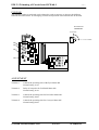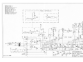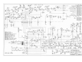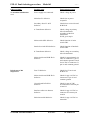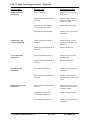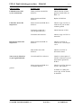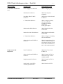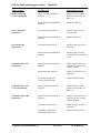
1
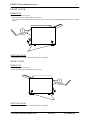
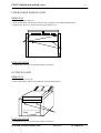
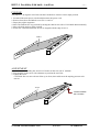
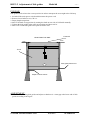
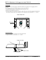
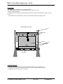
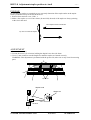
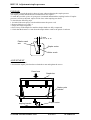
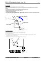
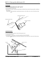
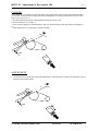
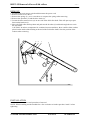
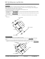
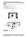
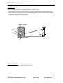
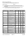
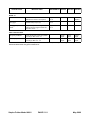
Stapler/Folder Model 60/61
Service manual
OCTOBER 1994
i Contents
T08011 TJ
PAGE
INTRODUCTION
ii
COVER REMOVE INSTRUCTION (CRI)
CRI 1.1
Front and rear cover
CRI 1.2
Infeed and outfeed covers
1.1
1.2
REPAIRS/ADJUSTMENTS (REP)
REP 2.1
Parallelity Fold knife - Anvil bar
2.1
REP 2.2
REP 2.3
REP 2.4
REP 2.5
REP 2.6
REP 2.7
REP 2.8
REP 2.9
REP 2.10
REP 2.11
REP 2.12
REP 2.13
REP 2.14
REP 2.15
REP 2.16
REP 2.17
REP 2.18
2.2
2.3
2.4
2.5
2.6
2.7
2.8
2.9
2.10
2.11
2.12
2.13
2.14
2.15
2.16
2.17
2.18
Adjustment of Side guides Model 60
Adjustment of Side guides Model 61
Adjustment of Side jogger movement Model 61
Parallelity Staple stop - Anvils
Parallelity Fold stop - Fold knife
Positioning staples on fold
Adjustment of stapler position to anvils
Adjustment of stapler pressure
Home position Stapler motor M1
Home position Fold knife motor M2
Adjustment of Eject Idler roller
Adjustment of Eject motor M4
Aligning Eject rollers
Removal of lower Fold rollers
Fold pressure, top Fold rollers
Removal of Infeed motor M6 assembly Model 61
Removal of Stapler head
ELECTRONIC DETAIL INFORMATION (EDI)
EDI 3.1
Trimming of circuit board PCB 60-1
EDI 3.2
Wiring/circuit diagram Model 61
EDI 3.3
Wiring/circuit diagram Model 60
EDI 3.4
PCB PL60 layout
EDI 3.5
PCB PL61 layout
3.1
3.2
3.3
3.4
3.5
FAULT ISOLATING PROCEDURE (FIP)
FIP 4.1
Fault isolating procedure Model 61
FIP 4.2
Fault isolating procedure Model 60
FIP 5. . 1
P reventive Maintenance
4.1-4.4
4.5-4.7
5.1-5.2
STAPLER FOLDER MODEL 60/61
PAGE i
OCTOBER -94
OCTOBER -94
OCTOBER -94
OCTOBER -94
OCTOBER -94
OCTOBER -94
OCTOBER -94
OCTOBER -94
OCTOBER -94
OCTOBER -94
OCTOBER -94
OCTOBER -94
OCTOBER -94
OCTOBER -94
OCTOBER -94
OCTOBER -94
OCTOBER -94
OCTOBER -94
OCTOBER -94
OCTOBER -94
OCTOBER -94
OCTOBER -94
OCTOBER -94
OCTOBER -94
OCTOBER -94
OCTOBER -94
OCTOBER -94
OCTOBER -94
MAY -02
OCTOBER -94
ii Introduction
T08011 TJ
GENERAL INFORMATION
This service manual describes both the Model 60 and the Model 61.
Also available is conversion kit instruction Model 60 to Model 61, installation instruction Model 61 and a spare
parts list Model 60/61.
PLOCKMATIC CHISEL POINT STAPLES
The staples that should be used in the Model 60/61 are PLOCKMATIC chisel point staples, part number 800001.
When using PLOCKMATIC staples functional disorders are avoided and the life length of the stapler heads are
radically increased.
SPECIAL TOOLS
There is a tool set available, part number 600007, in order to facilitate adjustments on Model 60/61.
Tool A
STAPLER FOLDER MODEL 60/61
Tool B
Tool C
PAGE ii
OCTOBER-94
CRI 1.1 Front and rear cover
T08010 TJ
FRONT COVER
REMOVAL
1. Loosen the two screws (1).
2. Pull out the lower end and lift up to remove.
CAUTION: Lift carefully when removing front cover to prevent damaging the wire harness to front
panel.
1
INSTALLATION
1. Installation is an exact reversed procedure of removal.
REAR COVER
REMOVAL
1. Loosen the two screws (1).
2. Pull out the lower end and lift up to remove.
1
INSTALLATION
1. Installation is an exact reversed procedure of removal.
STAPLER FOLDER MODEL 60/61
PAGE 1.1
OCTOBER-94
CRI 1.2 Infeed and outfeed cover
T08010 TJ
UPPER/LOWER INFEED COVER
REMOVAL
1. Remove the two screws (1).
2. Pull out the upper end of Lower infeed cover and open cover to horizontal position.
3. Remove the screws (2) and remove the upper infeed cover.
2
1
INSTALLATION
1. Installation is an exact reversed procedure of removal.
OUTFEED COVER
REMOVAL
1. Loosen the two screws (1).
2. Pull out the upper end of cover and open to horizontal position.
1
INSTALLATION
1. Installation is an exact reversed procedure of removal.
STAPLER FOLDER MODEL 60/61
PAGE 1.2
OCTOBER-94
REP 2.1 Parallelity Fold knife - Anvil bar
T08008 TJ
PURPOSE
The purpose is to align the Anvil bar with the Fold knife to obtain a correct staple position.
1. Switch off the main power switch and disconnect the power cord.
2. Remove front, Rear and Infeed cover CRI.1.1 and 1.2.
3. Empty the stapler magazines.
4. Move the Fold knife to top position by turning the shaft on rear side of Fold knife Motor manually.
5. Move the Side guides to outer position.
6. Insert tool A and check that the Anvils are aligned with the edge of tool A.
Tool A
ADJUSTMENT
1. Loosen the screw holding the Anvil bar a fraction on the rear side of machine.
2. Tap carefully on the screw with a hammer to position the Anvil bar.
3. Tighten the screw.
CAUTION: Do not move the Anvil bar up or down, that could cause the stapling pressure to be
uneven.
Tool A
LOOSEN SCREW
ON THIS SIDE
STAPLER FOLDER MODEL 60/61
PAGE 2.1
OCTOBER-94
REP 2.2 Adjustment of Side guides
Model 60
T08008 TJ
PURPOSE
Side guides needs to have the correct position in order to transport the set straight to the fold stop.
1. Switch off the main power switch and disconnect the power cord.
2. Remove lower Infeed cover, CRI 1.2.
3. Empty Stapler magazines.
4. Move Fold knife to top position by turning the shaft on rear side of fold knife manually.
5. Tighten the Side guides in the outer most position and insert tool A.
6. Move tool A until Side guide inner point is flush to tool.
Fold knife
VEIW FROM TOP SIDE
1mm
1mm
Tool A
Side guide flush to tool
Adjust on these screws
ADJUSTMENT
1. Loosen screws holding Side guides and adjust so that there is a 1mm gap at the lower end of Side
guides according to the figure.
STAPLER FOLDER MODEL 60/61
PAGE 2.2
OCTOBER-94
REP 2.3 Adjustment of Side guides Model 61
T08009 TJ
PURPOSE
The Side guides needs to be exactly parallel in order to transport the set straight to the Fold stop.
1. Switch off the main power switch and disconnect the power cord.
2. Remove lower Infeed cover, CRI 1.2.
3. Empty the Staple magazines.
4. Move the Fold knife to top position by turning the shaft on the rear side of Fold knife motor
manually.
5. Move the Side guides to the outer most position and insert tool A.
6. Check that the Side guides are flush to tool.
VEIW FROM TOP SIDE
Fold knife
Side guide flush to tool
Tool A
Side guide flush to tool
Adjust on these screws
ADJUSTMENT
1. Loosen the screws holding the Side guides, adjust until the Side guides are flush along the side of
tool A.
STAPLER FOLDER MODEL 60/61
PAGE 2.3
OCTOBER-94
REP 2.4 Adjustment of side jogger movement Model 61
T08009 TJ
PURPOSE
On the Model 61 the side jogging is performed with the rear jogging rail. The jogging stroke is
essential
to the jogging performance and the transport of stets to the fold area.
1. Switch off the main power switch and disconnect the power cord.
2. Remove lower Infeed cover, CRI 1.2.
3. Push the jogging rail in manually and make a mark with a pen, release the jogging rail and measure
the distance from the mark to the jogging rail. The jogging movement should be 3.5 +/- 0.5mm.
VIEW FROM TOP
Push here
ADJUSTMENT
1. Locate the Jogger arm assembly close to the Stapler motor.
2. Adjust on screw (1) to obtain the 3.5 +/- 0.5mm.
Jogger arm assy
1
Stapler motor
STAPLER FOLDER MODEL 60/61
PAGE 2.4
OCTOBER-94
REP 2.5 Parallelity Staple stop - Anvils
T08009 TJ
PURPOSE
The purpose is to obtain the correct staple position.
1. Switch off the main power switch and disconnect the power cord.
2. Empty Staple magazines.
3. Insert tool B according to the drawing and crank hand wheel to position upper edge of tool at
Anvils.
CAUTION. The clear Indicator switch could be damaged when inserting tool B.
VIEW FROM TOP SIDE
1
Staple stop
Tool B
2
Anvil bar
ADJUSTMENT
1. Loosen one of the screws at position (1) and two of the screws at position (2).
2. Adjust by skewing the staple stop carriage until tool B is aligned with the anvils.
3. Tighten the screws at position (1) and (2).
STAPLER FOLDER MODEL 60/61
PAGE 2.5
OCTOBER-94
REP 2.6 Parallelity Fold stop - Fold knife
T08009 TJ
PURPOSE
The purpose is to obtain the correct folding position.
1. Switch off the main power switch and disconnect the power cord.
2. Remove Outfeed cover, CRI 1.2.
3. Move Fold knife to top position by turning the shaft on rear side of fold knife motor manually.
4. Turn the hand wheel to fit tool C between the Fold stop and the Fold knife.
5. Check that the Fold stop is parallel with the Fold knife.
Fold knife
Turn here
Tool C
M2
ADJUSTMENT
1. Loosen the screws 1 and position the Fold stop parallel compared to the Fold knife.
NOTE. Loosen only the screws on one side of Fold stop, if loosen screws on both sides, staple
position on fold may have to be adjusted.
Fold knife
Tool C
M2
1
STAPLER FOLDER MODEL 60/61
PAGE 2.6
OCTOBER-94
REP 2.7 Positioning staples on fold
T08009 TJ
PURPOSE
The distance between the fold stop and the fold knife should be equal to the distance between the fold
knife and the staple outlet. Regardless of where the fold is positioned the staples should always be on
the fold.
1. Run a few sets of two sheets and check the position of the staples.
OK
ADJUSTMENT
1. Remove the nut (1).
2. Position the Fold plate by turning the set screw (2), clockwise will increase the length between
the Fold stop and the Fold knife.
NOTE. The Fold plate should be in an approximately 90o angle compared to the fixed part of the
Fold stop. It is not recommended to do a large adjustment on the set screw. If a large adjustment is
needed, loosen the screws (3) on both sides of Fold stop and go to REP. 2.5 for adjustment.
90
1
2
3
Fold plate
STAPLER FOLDER MODEL 60/61
PAGE 2.7
OCTOBER-94
REP 2.8 Adjustment stapler position to Anvil
T08009 TJ
PURPOSE
By checking the staples on a stapled set you can easely determine if the staple outlet on the stapler
head is positioned on top of the slot in the anvil.
1. Remove front and rear cover, CRI 1.1.
2. Make a few staples on a set of two sheets (do not fold), the ends of the staple are always pointing
at the slot in the anvil.
Move stapler head in this direction
Top view of misformed staples
ADJUSTMENT
1. Loosen the screw (1).
2. Loosen the screws (2) a fraction, holding the Stapler bar to the side frame.
3. Use a 17 mm wrench to turn the Stapler bar until the staples are formed correctly.
WARNING: This adjustment is performed with the power ON, make sure to stay clear from moving
parts.
2
1
Staper heads
Stapler head
Stapler bar
Anvil
STAPLER FOLDER MODEL 60/61
PAGE 2.8
OCTOBER-94
REP 2.9 Adjustment stapler pressure
T08009 TJ
PURPOSE
It is possible to staple through 22 sheets of paper without adjusting the stapler pressure.
The stapler pressure should increase when thick sets are stapled.
To make this possible a piece of spring steel is mounted underneath the stapling bracket. If stapler
pressure is incorrect adjusted, staples will be loose when stapling two sheets.
To check do the following steps.
1. Switch off the main power switch and disconnect the power cord.
2. Remove Infeed cover, CRI 1.2.
3. Empty the Staple magazines.
4. Press on top of the Stapler bar until the Stapler heads are fully compressed.
5. Check that the distance is 9 mm from the stapler Motor crank to the plastic Crank arm.
9 mm
Plastic crank
arm
Stapler motor
Motor crank
ADJUSTMENT
1. Loosen the screws (1).
2. Position the stapler yoke bracket to obtain the 9 mm and tighten the screws.
Press here
Stapler bar
Stapler yoke
bracket
1
1
stapling bracket
STAPLER FOLDER MODEL 60/61
Stapler motor
PAGE 2.9
OCTOBER-94
REP 2.10 Home position Stapler motor M1
T08009 TJ
PURPOSE
Switch SW7 stops the Stapler motor at home position.
There are two springs that holds the Stapler yoke in top position when Stapler motor is in home
position.
1. Switch off the main power switch and disconnect the power cord.
2. Remove Front and Infeed cover, CRI 1.1 and 1.2.
3. Empty the Staple magazines.
4. Turn the Stapler motor crank manually and check that Switch SW7 activates 0-1mm before motor
crank arm is aligned with plastic crank arm.
Turn motor in this direction
Plastic crank
arm
Stapler motor
Motor crank
0 -1mm
ADJUSTMENT
Locate Switch SW7 positioned on side frame operator side.
1. Loosen the screws (1).
2. Turn Stapler motor manually and stop when the plastic crank arm on the motor is 1mm
(5 degrees) before top dead centre.
3. Position SW7 so that it activates and tighten the screws (1).
SW7
1
STAPLER FOLDER MODEL 60/61
PAGE 2.10
OCTOBER-94
REP 2.11 Home position Knife motor M2
T08009 TJ
PURPOSE
Switch SW8 stops the Knife motor at home position.
1. Remove Front and Infeed cover, CRI 1.1 and 1.2.
2. Select folding on front panel.
3. Run one set of paper trough and check that the Fold knife stops below the paper path according to
the drawing.
WARNING: This adjustment is performed with power ON, make sure to stay clear from moving
parts.
Paper path middle section
Paper path lower section
Fold knife motor M2
Fold knife
ADJUSTMENT
Locate Switch SW8 positioned on side frame operator side.
1. Loosen the screws (1).
2. Position SW8 to obtain the correct home position for the Fold knife.
WARNING: This adjustment is performed with power ON, make sure to stay clear from moving
parts.
Fold knife motor M2
Fold knife
SW8
1
STAPLER FOLDER MODEL 60/61
PAGE 2.11
OCTOBER-94
REP 2.12 Adjustment of Eject Idler roller
T08009 TJ
PURPOSE
The upper Idler roller has to be positioned at the correct height in order for the Eject motor feed
wheel to feed the set to the Fold stop.
1. Switch off the main power switch and disconnect the power cord.
2. Measure the distance from the paper path to the lower end of the Idler roller.
Ruler
Paper path
Idler roller
5 mm
Eject motor feed wheel
S1
ADJUSTMENT
1. Adjust by carefully bending the bracket for Idler roller according to the drawing below.
5 mm
Bend here
S1
STAPLER FOLDER MODEL 60/61
PAGE 2.12
OCTOBER-94
REP 2.13 Adjustment of Eject motor M4
T08009 TJ
PURPOSE
There should be a clearance between the Idler roller and the Eject feed wheel when Solenoid SOL1
is activated. If Idler roller and Feed wheel are touching there could be a problem to feed sets with
large sizes (A3/11"x17").
1. Switch off the main power switch and disconnect the power cord.
2. Remove Infeed cover, CRI 1.2.
3. Press on the plunger for Solenoid SOL1 and view from the infeed side, the rollers will appear to
be
flush when there is a 2mm space in between them.
2 mm
SOL1
ADJUSTMENT
1. Loosen the screw on the rear side of Solenoid SOL1 and position the solenoid to obtain the correct
distance between the rollers.
2 mm
SOL1
STAPLER FOLDER MODEL 60/61
PAGE 2.13
OCTOBER-94
REP 2.14 Aligning Eject rollers
T08009 TJ
PURPOSE
This adjustment is more essential on the Model 61, when the set is fed to the Fold stop on a Model
61
the inner Side jogger rail will not guide the set as on a Model 60.
1. Switch off the main power switch and disconnect the power cord.
2. Remove lower Infeed cover, CRI 1.2.
3. Run a few sets and check that they are fed straight down to the Fold stop.
Upper idler roller
2
Feed wheel
SOL1
1
M4
Push here
ADJUSTMENT
1. Adjust the skewing of Feed wheel by loosening the screw (1) and turn the Feed motor assembly.
2. Align the Feed wheel with the upper Idler roller by positioning the set collars (2).
STAPLER FOLDER MODEL 60/61
PAGE 2.14
OCTOBER-94
REP 2.15 Removal of lower Fold rollers
T08009 TJ
REMOVE
1. Switch off the main power switch and disconnect the power cord.
2. Remove Front cover, CRI 1.1.
3. Remove the springs (1), use a screwdriver to compress the springs when removing.
4. Remove the sprockets (2) and the drive chain (3).
5. Loosen the sheet metal screws (4) on one side of the fold roller shaft. This will open up a space
between the brackets (5).
6. Move the Fold roller shaft up/down and push out the brackets (5) and shaft trough the cut out in
the side frame.
CAUTION: In order to compensate for variations between machines, there could be shim washers
placed on the inside of the bushing at the end of the Fold roller shafts. Note the position of the
washers when removing.
5
4
1
3
2
INSTALLATION
Installation is an exact reversed procedure of removal.
NOTE: When installing run the machine for a few revolution to let the sprockets "settle" before
tightening.
STAPLER FOLDER MODEL 60/61
PAGE 2.15
OCTOBER-94
REP 2.16 Fold pressure, top Fold rollers
T08009 TJ
PURPOSE
There are two springs on each side of the top Fold rollers, one is stiff and the other is softer.
When running two to five sheets the Fold rollers will only use the soft springs, when running up to
twenty sheets all of the springs will be compressed.
1. Switch off the main power switch and disconnect the power cord.
2. Remove Front and Rear cover, CRI 1.1.
3. Check that there is a 35 +/- 0.5mm space in-between the fold bracket and the fold roller arm at the
top spring.
4. Check that there is 35.5 +/- 0.5mm space in-between the fold bracket and the fold roller arm at the
lower spring.
5. Use a feeler gauge to check that there is a 2 +/- 0.5mm space in-between the screw (1) and the
fold
roller arm.
35+/-0.5mm
35.5+/-0.5mm
1
2.5+/-0.5mm
ADJUSTMENT
1. Start with adjusting screw (1) to a distance of 33mm.
2. Adjust the space between the fold bracket and the fold roller arm to 35+/- 0.5mm on the upper
screw.
3. Loosen the screws (2) and position the fold pressure assembly until the Fold rollers are in a
straight line with the fold pressure assembly and the distance at the lower spring is 35.5+/- 0.5mm.
Fold backet
2
Fold rollers
33mm
1
Fold roller arm
STAPLER FOLDER MODEL 60/61
PAGE 2.16
OCTOBER-94
REP 2.17 Removal of Infeed Motor M6 assembly, Model 61
T08009 TJ
PURPOSE
By removing the infeed motor assembly you will have an easy access to the infeed motor and infeed
roller.
1. Switch off the main power switch and disconnect the power cord.
2. Remove Infeed covers, CRI 1.2
3. Disconnect the Infeed Motor M6 from the wire harness.
4. Remove the stud (1).
5. Push down the Infeed Motor assembly to by pass mode.
6. Push on the Infeed Motor assemble indicated in the drawing until it passes over the edge (2).
7. Move the Infeed Motor assembly left/right and lift out.
VIEW FROM TOP
1
VIEW FROM INFEED SIDE
2
Infeed motor
assembly
Push here
INSTALLATION
Installation is an exact reversed procedure of removal.
STAPLER FOLDER MODEL 60/61
PAGE 2.17
OCTOBER-94
REP 2.18 Removal of Stapler head
T08009 TJ
REMOVAL
1. Switch off the main power switch and disconnect the power cord.
2. Remove the Stapler head by removing the pin 1 trough the hole 2.
NOTE. Older machines does not have the hole 2 in the stapler bracket. On these machines the
screws 3 has to be removed in order to remove the stapler head. Before removing make a mark to
reposition the stapler head when replacing.
Stapler bracket
1
2
3
INSTALLATION
Installation is an exact reversed procedure of removal.
STAPLER FOLDER MODEL 60/61
PAGE 2.18
OCTOBER-94
EDI 3.1 Trimming of Circuit board PCB 60-1
T08009 TJ
PURPOSE
The trimmers on the circuit board can be adjusted in order to increase or decrease the different
functions described below. If exchanging a circuit board position of the trimmers has to checked.
SETTING OF
TRIMMERS
9 O’clock
12 O’clock
TR 1
TR 2
TR 3
TR4
ADJUSTMENT
Trimmer 1
Controls the operating time of the Eject Motor M4.
Normal setting 12:30.
Trimmer 2
Delay of start pulse for Fold knife Motor M2.
Normal setting 11:00.
Trimmer 3
Controls the operating time for Fold roller Motor M3.
Normal setting 10:00.
Trimmer 4
Controls the operating time for Conveyor Motor M5.
Normal setting 09:00.
STAPLER FOLDER MODEL 60/61
PAGE 3.1
OCTOBER-94
FIP 4.1 Fault isolating procedure Model 61
T08012 TJ
Observed fault
Possible cause
Fault isolating/repair
No machine initialisation.
cord.
Power supply not connected.
Check voltage in power
Main fuse F3 defective.
Check fuse at power
receptacle.
Secondary fuses F1 & F2
defective.
Check fuses at circuit board
PCB PL60.
1. Transformer defective.
Check voltage at primary
side of transformer,
according to label on
transformer.
If OK, go to step 2.
Main switch SW1 defective.
Check function of main
switch SW1.
Interlock switch SW6 defective.
Check function of Interlock
switch SW6.
2. Transformer defective.
Check voltage on secondary
side of transformer.
Main circuit board PCB PL60
defective.
Check for approximately 34
VDC at connector J1 pin 15
and common ground. Check
for 24 VDC at connector J1
pin 21 and common ground.
Fuse F2 defective.
Check fuse F2 at circuit
PCB PL 60.
Main circuit board PCB PL60
defective.
Check for app. 34 VDC at
Connector J1 pin 15 and
common ground.
Circuit board PCB PL61
defective.
Check for app. 0 VDC
at connector J5 between pin
22 and 25.
Interface cable/wire harness
defective.
Check for app. 22 VDC at
connector J5 between pin
4 and 8.
Infeed motor M6 defective.
Check for app. 34 VDC at
motor M6.
Infeed motor M6
inoperative.
STAPLER FOLDER MODEL 61
PAGE 4.1
OCTOBER-94
FIP 4.1 Fault isolating procedure Model 61
T08012 TJ
Observed fault
Possible cause
Fault isolating/repair
Stapler motor M1
inoperative.
Fuse F2 defective.
Check fuse F2 at circuit
PCB PL 60.
Main circuit board PCB PL60
defective.
Check for app. 34 VDC at
Connector J1 pin 13 and
common ground.
Staple mode switch SW 2
on front panel defective.
Check function of SW2.
Stapler motor M1 defective.
Check for app. 24 VDC at
motor M6.
Home position switch SW7
defective.
Check function of home
position switch SW7, see
REP 2.10.
Main circuit board PCB PL60
defective.
Replace PCB PL60.
Eject solenoid S1 defective.
Check for app. 34 VDC
at solenoid S1.
Main circuit board PCB PL60
defective.
Replace PCB PL60.
Eject motor M4 defective.
Check for app. 24 VDC at
motor M4.
Main circuit board PCB PL60
defective.
Check for app. 24 VDC
at connector J1 between pin
4 & 5.
Main circuit board PCB PL60
defective.
Check for app. 24 VDC at
connector J1 pin 14 and a
common ground.
Fold mode switch SW 3
on front panel defective.
Check function of SW3.
Knife motor M2 defective.
Check for app. 24 VDC at
motor M2.
Stapler motor M1
cycles continuously.
Eject solenoid S1
inoperative.
Eject motor M4
inoperative.
Fold knife motor M2
inoperative.
STAPLER FOLDER MODEL 61
PAGE 4.2
OCTOBER-94
FIP 4.1 Fault isolating procedure Model 61
T08012 TJ
Observed fault
Possible cause
Fault isolating/repair
Fold knife motor M2
cycles continuously.
Home position switch SW8
defective.
Check function of home
position switch SW8, see
REP 2.11.
Main circuit board PL60
defective.
Replace PCB PL60.
Main circuit board PCB PL60
defective.
Check for app. 24 VDC at
connector J1 pin 22 and a
common ground.
Fold mode switch SW 3
on front panel defective.
Check function of SW3.
Fold motor M3 defective.
Check for app. 24 VDC at
motor M3.
Main circuit board PCB 60
defective.
Check for 24 VDC at
connector J6 between pin
1 & 2.
Belt stacker motor M5
defective.
Check for 24 VDC at
belt stacker motor.
Circuit board PL61 defective.
Check for a short pulse of
24VDC connector J5 pin 10
and common ground on
PCB 61.
Main circuit board PCB 90-1
in collator defective.
Check for 24 VDC between
J2 pin 1 and common
Fold roller motor M3
inoperative.
Belt stacker motor M5
inoperative.
Jam occurs in Model 61
no jam signal indicated.
ground
on PCB 90-1. When jam
occurs app. 0 VDC should
be obtained.
STAPLER FOLDER MODEL 61
PAGE 4.3
OCTOBER-94
FIP 4.1 Fault isolating procedure Model 61
T08012 TJ
Observed fault
Possible cause
Fault isolating/repair
False jam indication
from Model 61.
Main circuit board PL60
defective.
Check for app. 24 VDC at
connector J1 between pin
10 and common ground.
Circuit board PL61
defective.
Check for app. 24 VDC at
connector J5 between pin
23 and common ground.
Start switch SW9 defective.
Check for app. 24 VDC at
connector J5 between pin
15 and common ground.
Check for app. 30 VDC at
connector J5 between pin
1 and 16.
Main circuit board PCB 90-1
in collator or interface cable
defective.
Staple position not
on fold.
Fold not straight.
Staples deformed.
Staple stop not parallel
compared to anvils.
See REP 2.5.
Fold plate not in correct
position.
See REP 2.7.
Fold stop not in correct
position.
See REP 2.6.
Side guides not straight.
See REP 2.3.
Eject Idler roller not in
correct position.
See REP 2.12.
Eject motor not in correct
position.
See REP 2.13.
Eject Idler rollers not aligned.
See REP 2.14.
Staple position to anvils not
correct.
See REP 2.8.
Staple pressure not correct.
See REP 2.9.
STAPLER FOLDER MODEL 61
PAGE 4.4
OCTOBER-94
FIP 4.2 Fault isolating procedure Model 60
T08012 TJ
Observed fault
Possible cause
Fault isolating/repair
No machine initialisation.
cord.
Power supply not connected.
Check voltage in power
Main fuse F3 defective.
Check fuse at power
receptacle.
Secondary fuses F1 & F2
defective.
Check fuses at circuit board
PCB PL60.
1. Transformer defective.
Check voltage at primary
side of transformer,
according to label on
transformer.
If OK, go to step 2.
Main switch SW1 defective.
Check function of main
switch SW1.
Interlock switch SW6 defective.
Check function of Interlock
switch SW6.
2. Transformer defective.
Check voltage on secondary
side of transformer.
Main circuit board PCB PL60
defective.
Check for approximately 34
VDC at connector J1 pin 15
and common ground. Check
for 24 VDC at connector J1
pin 21 and common ground.
Fuse F1 defective.
Check fuse F1 at circuit
PCB PL 60.
Main circuit board PCB PL60
defective.
Check for app. 24 VDC at
Connector J1 pin 13 and
common ground.
Stapler motor M1 defective.
Check for app. 24 VDC at
motor M6.
Staple mode switch SW 2
on front panel defective.
Check function of SW3.
Stapler motor M1
inoperative.
STAPLER FOLDER MODEL 60
PAGE 4.5
OCTOBER-94
FIP 4.2 Fault isolating procedure Model 60
T08012 TJ
Observed fault
Possible cause
Fault isolating/repair
Stapler motor M1
cycles continuously.
Home position switch SW7
defective.
Check function of home
position switch SW7, see
REP 2.10.
Main circuit board PCB PL60
defective.
Replace PCB PL60.
Eject solenoid S1 defective.
Check for app. 34 VDC
at solenoid S1.
Main circuit board PCB PL60
defective.
Replace PCB PL60.
Eject motor M4 defective.
Check for app. 24 VDC at
motor M4.
Main circuit board PCB PL60
defective.
Check for app. 24 VDC
at connector J1 between pin
4 & 5.
Main circuit board PCB PL60
defective.
Check for app. 24 VDC at
connector J1 pin 14 and a
common ground.
Knife motor M2 defective.
Check for app. 24 VDC at
motor M2.
Fold mode switch SW 3
on front panel defective.
Check function of SW3.
Fold knife motor M2
cycles continuously.
Home position switch SW8
defective.
Check function of home
position switch SW8, see
REP 2.11.
Fold roller motor M3
inoperative.
Main circuit board PCB PL60
defective.
Check for app. 24 VDC at
connector J1 pin 22 and a
common ground.
Fold motor M3 defective.
Check for app. 24 VDC at
motor M3.
Fold mode switch SW 3
on front panel defective.
Check function of SW3.
Eject solenoid S1
inoperative.
Eject motor M4
inoperative.
Fold knife motor M2
inoperative.
STAPLER FOLDER MODEL 60
PAGE 4.6
OCTOBER-94
FIP 4.2 Fault isolating procedure Model 60
T08012 TJ
Observed fault
Possible cause
Fault isolating/repair
Belt stacker motor M5
inoperative.
Main circuit board PCB 60
defective.
Check for 24 VDC at
connector J6 between pin
1 & 2.
Belt stacker motor M5
defective.
Check for 24 VDC at
belt stacker motor.
Staple stop not parallel
compared to anvils.
See REP 2.5.
Fold plate not in correct
position.
See REP 2.7.
Fold stop not in correct
position.
See REP 2.6.
Side guides not straight.
See REP 2.2.
Eject Idler roller not in
correct position.
See REP 2.12.
Eject motor not in correct
position.
See REP 2.13.
Staple position to anvils not
correct.
See REP 2.8.
Staple pressure not correct.
See REP 2.9.
Staple position not
on fold.
Fold not straight.
Staples deformed.
STAPLER FOLDER MODEL 60
PAGE 4.7
OCTOBER-94
MAI 5.1 Preventive Maintenance
Preventive Maintenance Bookletmaker Model 60 / 61
Service interval:
80 000
Note: All INSTRUCTIONS are referring to the Stapler folder Model 60 / 61 Service Manual.
The REFERENCE column is referring to the Spare parts list of Model 60 / 61 revision date
November 1994.
Important: If any of the checkpoints show indication of wear at any point, replace the part.
When lubricating, clean the surface before applying new lubricant
CHECK POINT
INSTRUCTION
R E FE R E N C E
80 000
160 000
240 000
All Machine, Paper paths
etc.
Use a vacuum cleaner, towels and
brushes to clean the machine from
paper dust. Use an alcohol to clean
from ink.
Clean
Clean
Clean
Stapler head (2 pcs.)
Clean stapler heads from glue and
apply ball bearing grease on drive bar.
Check adjustment REP 2.8 - 2.10
Clean/Grease
Clean/Grea se
Check/
Replace
O-ring on Eject feed wheel.
Use a rubber reactivator alcohol fluid.
Check for wear. If worn replace. Always
replace at 160 000.
Page 1.14Item 4
Clean
Replace
Clean
Staple motor and Staple
motor Home position.
Apply silicon grease between Motor
crank and plastic crank arm. Check
adjustment according to REP 2.10.
Page 1.12
Item 10 & 11
Check/
Adjust
Check/
Adjust
Check/
Adjust
Lifting clamp.
Apply silicon grease between Stapler
head and Lifting clamp.
Page 1.10
Item 5
Grease
Grease
Grease
Chain.
Apply chain oil. Check for wear, if worn
replace.
Oil
Oil
Oil
Chain idler wheel
Apply chain oil and check for wear, if
worn replace.
Page 1.20
Item 3 & 10
Oil/
Check
Oil/
Check
Check/
Replace
Rubber rings on Lower fold
rollers.
Use a rubber reactivator alcohol
fluid.Check for wear. If worn replace.
Page 1.18
Item 11
Clean
Clean/
Check
Check/
Replace
Lower Fold roller Flanged
bushing.
Under the top cover, use oil between
the Flanged bushings and shaft. Check
for wear, if worn replace.
Page 1.18
Item 8
Upper fold rollers.
Use a rubber reactivator alcohol fluid.
Bushing on Upper fold
rollers. *
Under the top cover, use oil between
the Flanged bushing and shaft. Apply
grease between bushings and side
frame. Replace at 160 000.
Page 1.18
Item 6
Fold knife guides (2 pcs.)
Apply grease on vertical rods.
Page 1.16
Item 1
Side jogger movement
(Only Model 61)
Inside the infeed cover, apply grease on Page 2.10
screw between jogger linkage and
Item 6
lower stapler bracket.
Grease
Grease
Grease
V-belt on Belt stacker
motor.
Check for wear. If worn replace.
Page 1.24
tem 4
Check
Check
Check/
Replace
Transport belts on Belt
stacker.
Use a rubber reactivator alcohol
fluid.Check for wear. If worn replace.
Page 1.22
Item 10
Clean
Clean
Replace
Stapler Folder Model 60/61
PAGE 5.1.1
Check/Oil
Clean
Clean
Clean
Oil
Replace
Oil
(Old
machines)*
Grease
May 2002
CHECK POINT
INSTRUCTION
R E FE R E N C E
80 000
160 000
240 000
INFEED MODULE
MODEL 61
Infeed wheel
Use a rubber reactivator alcohol
fluid.Check for wear. If worn replace.
Page 2.9
Item 8
Clean
Clean
Check/
Replace
Plastic guide included in
Back jogger
Apply grease between the oblong hole
and the metal pivot pin (4x).
Page 2.8
Item 5
Check
Grease
Check
Back jogger adjustment
bracket.
Apply a thin layer of silicon grease
between the Rear jogger bracket and
the bottom frame.
Page 2.8
Item 3
Check
Grease
Check
FINAL CHECK POINTS
Side guide parallelism
Check that the side guides are parallel
according to REP 2.2 or 2.3.
Check/
Adjust
Check/
Adjust
Check/
Adjust
Booklet quality
Check the booklet quality and adjust
according to REP 2.5 - 2.9.
Check/
Adjust
Check/
Adjust
Check/
Adjust
*From serial number 60161319 (Model 60) and serial number 61061366 (Model 61) the bushing is made of plastic
instead of metal. Please use grease instead of oil.
Stapler Folder Model 60/61
PAGE 5.1.2
May 2002