1
0:/7„e3
o,
ir
4-0/041-/
ADDENDUM NO. 1
RUHLIN•PANZICA*JENKINS
RPJ
C
July 20, 2010
ONSTRUCTION MANAGERS
MODIFICATIONS TO THE
BIDDING DOCUMENTS
FOR
BUCHTEL / PERKINS COMMUNITY LEARNING CENTER
PHASE 3— CLC PACKAGE
S'he
M
ISSUED BY:
GPD ASSOCIATES
RUHLIN/PANZICA/3ENKINS
ISSUED TO:
ALL BIDDERS
GENERAL
1.
A.
This addendum covers changes to the Documents and in closing the Contract will
become a part thereof. Each Bidder shall include these items to the extent they effect
his bid.
B.
These items modify only the portion of the Documents specifically noted. All odltr
wording remains In effect.
PROJECT MANUAL
2.
A. Specification Section 01500, TEMPORARY FACILITIES
1. ADD attached "Akron Public Utilities Bureau Notice to Contractors" to the end of
this section.
B. BIDDER SCOPE CLARIFICATION QUESTIONS:
Q:
A:
CM
Will background checks be required?
No
•
All other questions received up through July 19, 2010 that have responses, can be found in
GPD Associates portion of Addendum #1.
•
Deadline for submission of Pre-Bid questions is 12:00 Noon, Wednesday July 28, 2010.
BUCHTEL / PERKINS PHASE 3 — CLC PACKAGE ADDENDUM NO. 1
.,
3.
PRE-BID MEETING MINUTES
A. Pre-Bid Meeting Minutes are available for review upon request by contacting the CM and
are for reference only.
SEE ATTACHED ADDENDUM #1 FROM GPD ASSOCIATIES
CM
BUCHTEL / PERKINS PHASE 3— CLC PACKAGE ADDENDUM NO. 1
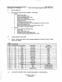
Ra ndall A. Monteith, P.E.
Pilots Administrator
Brian M. Gresser, P.E.
WPC Plant Administrator
Andre L Blaylock
Business Services Administrator
James L Six, P.E.
Water Supply Plant Administrator
DONALD L PLUSQUELLIC
Mayor
Gerald Holland, Director
DEPARTMENT OF PUBLIC SERVICE
Michael L McGlInchy, P.E.
PUBLIC UTILITIES BUREAU MANAGER
GENERAL NOTICE TO CONTRACTORS
February 1, 2005
SUBJECT: Unauthorized Use of Fire Hydrants
Dear Sirs:
The unauthorized use of fire hydrants is illegal and causes many 'problems for the City of Akron, particularly the
Public Utilities Bureau. The major problems associated with unauthorized hydrant usage are:
1. Potential to create a backflow condition wherein a toxic or bacteriological contaminant may enter the Akron
Water Distribution System, causing consumer illness or death.
2. Potentiai unknown hydrant damage that could hinder local fire department operations.
3. Discolored water problems for residents and businesses.
4. Potential water distribution system damage.
Various sections of the City of Akron Ordinances Akron Water Works Rules & Regulations, Ohio Revised Code,
and the Ohio Environmental Protection Agency Regulations make unauthorized operation of a fire hydrant illegal.
The City of Akron, Public Utilities Bureau has instituted new procedures to discourage the unauthorized usage of
fire hydrants, including filing a police report and pursuing prosecution of violators.
' need temporary water service for a construction project within the limits of the City of
PLEASE NOTE: 11 ysiu
Akron water uistnbution System, please contact our Utilities Business Office at (330) 375 -2027 to make ' •
arrangements for a temporary water account
All "Hydrant Meter Temporary Connections" supplied by the Akron Public Utilities Bureau are equipped with RPZ
backffow preventers. The connections are available in the following diameter sizes and maximum flow ratings based
on GPM (gallons per minute):
3/4" - 30 GPM
1W -150 GPM
3" - 300 GPM
Approval of applications for temporary water service are based on:
of work being performed.
1. Type
e meter size requested.
2. Th
3. The capacity of the water distribution system at a particular construction site to supply the maximum GPIY
requested.
Other than local fire department employees, only employees authorized by the Akron Public Utilities Bureau an
d to operate tire hydrants on the Akron Water Distribution System, as well as install, move, or remove fin
permitte
hydrant meter assemblies. We ask for your cooperation in eliminating the unauthorized use of hydrants.
Thank You,
killet‘. #12 ••."
erald . Holland, Director
Department of Public Service
Water Distribution Division • 565 Johnston Street • Akron, Ohio 44311 • 330-3 75-2420 • 330-375-2301 (lax) • www.ci.akron.oh.uE
05 - 23-0 6
03:00R1
FROM-Cavanau g h Builders
Ran dall A. Monteith, P.P.
Pilots Administrator
330-753-0229
F-513
P.002
1-OT1
Brian r Crosson P.E.
WPC Plant Administrator
James L Six, P.E.
Andre L Blaylock
Business Services Administrator
Water Supply Plant Administrator
DONALD L PLUSQUELLID
Mayor
Gerald Holland, Director
DEPARTMENT OF PUBLIC SERVICE
Michael L McGlInchy, P.E.
PUBLIC UTILITIES BUREAU MANAGER
May 15, 2006
Cavanaugh Builders
1744 Collier Road
Akron, Ohio 44320
Subject:
New 4 Inch and Larger Water Service Installation Policy
To Whom It May Concern:
The City of Akron, Public Utilities Bureau has Instituted changes In contractor requirements for installation of 4Inch and larger water services. EFFECTIVE IMMEDIATELY, Public Utilities Bureau personnel will install the tap
and valve only for any new 4-Inch or larger service. Projects that were initiated before the effective date will be
exempt from these changes.
As the Owner/Contractor you will have additional responsibilities when installing these water services. You will be
required to perform the following:
•
•
•
•
•
install pipe within right-of-way to approximately seven feet from the pubic water main
Expose the water main
Assist Akron Water Department personnel in maneuvering the tapping machine
Backfill the excavation (according the local jurisdiction guidelines)
Perform complete restoration within the Street Right-of-Way (according to local jurisdiction guidelines)
The pipe will continue to be Inspected under the current Houseline Inspection Program. To schedule this
inspection, contact Kurt Heffernan at (330) 375-2420.
As the Owner/Contractor you will continue to be responsible for obtaining all permits, approvals, and costs relating
to the service installation, Including the 'Street Opening" Permit from the applicable government authority. Also,
forward a copy of the 200psI hydrostatic pressure test on the houseline via fax to this office at (330) 376-2418.
If you have any questions, please contact me at (330) 375-2690, ext. 6413.
CC 3i/oeivw2Wr5
Sincerely,
iteg-Lai
Sm./m/97-6RJ
oseph A. Okolish
Utilities Engineering
JAO:rnh
146 S. High Street • Room 300 • P.O. Sox 3666 • Akron. Ohio 44309-3665 • (330) 376-2890 •FAX (330) 375-2418
www.clehron.on.us
2007271.15
ADDENDUM NO. 1
to
BIDDING DOCUMENTS
For
PHASE 3— CLC PACKAGE
BUCH'TEL/PERICINGS COMMUNITY LEARNING CENTER
July 20, 2010
A. The original bidding documents for the above-referenced project are hereby amended as
noted in Addendum No. 1.
B. This Addendum supersedes and takes precedence over information provided prior to the
date of this Addendum.
C. This Addendum includes:
1. Addendum No. 1 — 9 pages.
2. Sketches: C-1; S-072010-01, S-072010-02, S-072010-03, A-1 thru A-22;
T103-A, P-072010-01 thru P-072010-10, M-072010-1 thru M-072010-03,
E-072010-01 thru E-072010-06,
F-072010-01
3. Sheets: S-103; S-111; S-1I6; S-513; S-514; A-104;I-103; I-131; A-601; A-602;
P-104, P-614, M-103,M-405, E-I17, E-617, E-506A.
4. Specifications — 04810, 08520, 08710, 09640, 09900, 10432, 10505, 11450,
12494, 12900, 15561, 15562, 15852, 15853, 16120, 16461, 16555.
GENERAL
1. DESIGN CLARIFICATIONS
1. Building section A3/A-303A is not shown on A-101 or A-lb as it should
be. However, section's location is shown in key plan on A-303A. This,
along with the room labels shown within the section, provides ample
information for bidders to locate section mark on overall plan sheets.
2. SUBSTITUTION REQUESTS
1. Citadel Architectural Products submitted a request for Envelope 2000 RR to
be considered as an approved equal to manufacturers indicated under
Section 07412 2.4.A.
a. This product is not approved for use on this project.
2. Wood-Metal Industries submitted a request for wood cabinets and tables to
be considered as an approved equal to manufacturers indicated under
Section 12355 2.4.B.
a. This product is not approved for use on this project.
3. Peerless Products submitted a request for G-200 Series to be considered as
an approved equal to products indicated under Section 08520 2.2A.
a. This product is approved for use on this project.
4. Mule-Hide Products submitted a request for Mule-Hide White-on-Black
EPDM to be considered as an approved equal to manufacturers indicated
under Section 07531.2.1.A.
a. This product is not approved for use on this project.
1
..
5. Capital Cast Stone submitted a request for cast stone masonry to be
considered as an approved equal to manufacturers indicated under Section
04720.2.3.A.
a. This product is not approved for use on this project.
6. Action Floor Systems submitted a request for Action Pro Air to be
considered as an approved equal to manufacturers indicated under Section
09642.2.1.A.1 and 09640.2.1.A.1.
a. This product is approved for use on this project.
7. Tom Sexton and Associates submitted a request for Jasper Library Furniture
to be considered as an approved equal to manufacturers indicated under
Section 12900.
a. These products are not approved for use on this project.
3. QUESTIONS
1. Question: Although the last page of the Specification indicates that the
Roller Shades required are in Rooms 313, 418, 418D and 421, I cannot find
these rooms on the Architectural Plans.
Response: These rooms do not exist on this project. Disregard the schedule
at the end of the spec, is not edited for this project.
2. Question: Is there a need for external wireless access points?
Response: No.
SPECIFICATIONS
1. Spec Section 04810 Unit Masonry Assemblies: 2.2/C/1 The unit compressive
strength of all cmu has been changed from 1900 psi to 2800 psi.
2. Spec Section 08520 Aluminum Windows: Lintex Inc.; L1000T Series has been
added as an acceptable manufacturer.
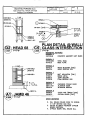
3. Spec Section 08710 Finish Hardware: The following hardware sets have been
revised: #4 — door 147AA removed; #15 — door changed to B172B; #15A — door
material changed to AL from HM; #26B — "smoke" label added to set; #27 — Door
113A removed; #30 — removed door Cl1A; added #32 for door C 11A; #34 —
removed door P100A; added #34A for door PIMA; #46A — door height and hinge
height changed; #49 — door heights changed; #51A — removed door G204A; #52 —
added door G204A; #79 — removed door G203B; #82 — door number changed; # 95
— added door P100C; #102B — added fire rating to door and revised hardware; #112
— door size revised; #113 — added door EEC; added #115 for door B113A; added
#116 for door B147AA.
4. Spec Section 09640 Wood Flooring and 09642 Wood Athletic Flooring: Action
Floor Systems; Action Pro Air System has been added as an acceptable
manufacturer.
5. Spec Section 09900 Painting: Revise paint color P-12 to A1144 Real Teal.
6. Spec Section 10432 Exterior Identification Letter Signage: 2.2/C Font: Anal.
Color: Dark Bronze.
2
7. Spec Section 10505 Metal Lockers: Revise section 2.4/C13 to read - [Type 7]: 12"
wide x 15" deep x 72" high, single tier. Refer to drawings.
8. Spec Section 12494 Roller Window Shades: Revise section 2.2/A/4 to read Control System: Crank mechanism, five foot long minimum handle, removable;
section 2.2/B/1 to read - Draper Shade & Screen Co., Inc.; Motorized Flexshades;
add 4.1 schedule (attached).
9. Spec Section 12900 Loose Furnishings (Room Schedule): Revised furnishings called
out in Masonry Lab B146 and related support spaces and revised any reference to
"Auto Collision" to "Masonry."
10. Spec Section 11450 Appliances: Revise section 2.1/L to read - Science Prep Room
Dishwasher (S11): Built-in dishwasher, Energy Star compliant, stainless steel tub, quiet
package, hard food disposer, ADA compliant.
i. GE, Model GLD4408RWW (white)
ii. Frigidaire, Model FDB2410HI (white)
iii. Whirlpool, Model GU3100XTV(white)
11. Spec Section 15561, Direct Fired Heating & Ventilating Units, Delete entire Section
from this project.
12. Spec Section 15562, Indirect Fired Heating & Ventilating Units, Revise section 1.2A.
to read "MAU-1 and MAU-2"
13. Spec Section 15852, Paint Booth System, Delete entire Section from this project.
14. Spec Section 15853, Welding Exhaust System, Delete entire Section from this
project.
15. Spec Section 16120, Conductors and Cables, Revise section 2.1 and 3.4. Encore
wire is approved for this project. Conductor Splices: Not permitted unless
specifically noted on construction drawings.
16. Spec Section 16461, Dry Type Transformers, Revise section 2.2 and 2.3. High
efficiency dry type transformers, type CSL-3 are required for this project.
17. Spec Section 16555 Stage Lighting has been replaced in its entirety due to various
changes.
DRAWINGS
CIVIL
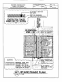
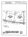
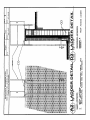
1. Sheet C-102: the location and typical section of the construction trailer stone pad has
been added. The area of the trailer stone pad shall be restored to a lawn area upon
completion of construction. The access route to the stadium will be maintained as a
stone pavement in accordance with the current "stone pavement section..." the
proposed 8' high construction fence and 16' double swing gate shall be installed as
per Al stage phase plan along the south side of the construction trailer stone pad. A
16' double swing gate will not be installed across the Glendora Avenue entrance to
the stadium access stone pavement. See sketch C-1.
STRUCTURAL
3
1. Sheet S-103: Revised Area 'C' Masonry Lab slab-on-grade work.
2. Sheet S-111: Revised Area 'C' Masonry Lab roof framing.
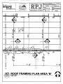
3. Sheet S-116: Revised Area 'H' roof framing and added new section cuts.
4. Sheet S-513: Revised Sections D1, E6, and D6.
5. Sheet S-514: Added Sections B4, B5, and B6.
6. Sketch S072010-01: Revised lintels in Area 'B'/Roof Framing Plan along South
Wall.
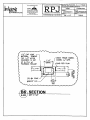
7. Sketch S072010-02: Revised section B6/S-502. Ref: Masonry Lab revisions.
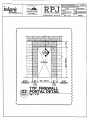
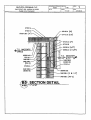
8. Sketch S072010-03: Added Section D2/S-511 - Firewall Portal Detail
AR,c1IITECTURAL
I. Sketch A-1: revised fascia detail at SW corner only of Gymnasium P101. Fascia
design at this location reflects tapered insulation and roof drain design where
gymnasium roof meets Perkin's Lobby's east wall.
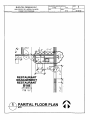
2. Sheet G-001: Fire extinguisher tag 'FE' changed to 'FEC' on east wall of BlOOM;
Class C rating for fire extinguishers in Masonry Lab B146, no longer needed, due to
room type change. Both fire extinguishers in the room will be type 'ABC'; Fire
extinguisher tag TEC' in lobby G001 has moved to correct location on outside of
the north wall of Concessions G104. See sketch A-10; Fire extinguisher and fire
extinguisher tag 'FE' added to G104. See sketch A-10; Fire extinguisher and fire
extinguisher tag 'FE' added to G100. See sketch A-10.
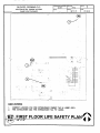
3. Sheet G-002: Fire extinguisher cabinet tag TEC' added for fire extinguisher cabinet
on south wall of Corr. C24, outside of room P201. See sketch A-11; Fire
extinguisher tag 'FE' added for fire extinguisher in Control Room B248. See sketch
A-11; Fire extinguisher cabinet tag TEC' added for fire extinguisher cabinet on
north wall of corr. C20, outside of classroom B205. See sketch A-11; Fire
extinguisher cabinet tag TEC' moved from south wall of Corr. C20, outside of B210,
to correct location at top landing of stair 2STB. See sketch A-11; Fire extinguisher
tag 'FE' moved from Life Skills P218A to Life Skills Lab. P218. See sketch A-11.
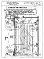
4. Sheet AD-101: Sheet Keynote 31 now reads: "Existing wood athletic flooring to
remain. Refinish under Alternate no. A-7."; Sheet Keynote 32 now reads:
"Remove existing VCT flooring. Clean floor of adhesives to receive floor finish as
scheduled."; Existing bleachers in Existing Gymnasium 0100 will be removed.
Sheet keynote 35 added reads: "Remove existing bleachers and accessories."; Sheet
Keynote #2, at existing entry door to existing staff restroorn/shower, changed to
Sheet Keynote #3; Demolition work of Existing gym is included in alternate #A-1.
Sheet title updated.
5. AD-102: Sheet Keynote 3 now reads: "Remove 7'-4"H portion of wall to
accommodate new door and frame. See plan sheet A-116."; Demolition work of
Existing gym is included in alternate #A-1. Sheet title updated.
6. A-IO2: Dimensions have been revised in room B148. See sketch A-9.
7. A-I04: One (1) Chinning bar added to north-west wall of Auxiliary Gym B156. See
sketch A-13.
4
8.
A-105: Brick veneer on the north wall of 8169 has been labeled as walLtype 11A.
See sketch A-18.
9.
A-106: Wall section marker A5/A-304, at north exterior wall of Mech. B159, has
been mirrored to accurately correspond with wall section A5/A-304.
10. A406: Room B159 Mechanical room. Fire extinguisher has been relocated from
behind door to just south of GWH-1.
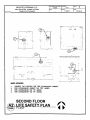
11. A-107: Two (2) chinning bars added to Gymnasium P101 at south and north walls.
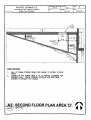
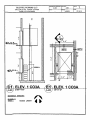
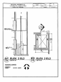
See sketch A-14; Wall section marker A2/A-3 12 has been removed from elevator 2.
The enlarged plan and section of this elevator is now shown on sheet A-403; In
Gymnasium P101, the rectangles shown at telescopic bleachers have been referenced
as scorers tables 12660.8. There is now a total of three scorers tables in Gymnasium
P101.
12. A-109: Sheet keynote 17 placed at south-east wall of corridor GOO. See sketch A-15.
13. Sheet A-I 13: Detail C2/A-504 created for expansion joint at intersection of
auditorium and mechanical room 242. See sketch A-22.
14. Sheet A-114: Shaft 'A' - Walls of Drama Storage B155, below, are to extend up
through Shaft 'A' and up to the deck above. Louver `LV4', in shaft A has shifted 4'0" to accommodate extension of drama storage room walls. See sketch A-12. North
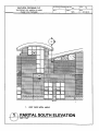
exterior elevation has also been updated to reflect this change.
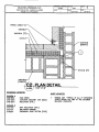
15. Sheet A-123: Rooms BlOOG and B IOW- separating wall has been revised. Key note
13 has been revised. See sketch A-7.
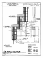
16. Sheet A-307: Wall Section A3 has been updated. Refer to Sketch A-8.
17. Sheet A-403: Rooms BIOOG and B100.1 dimensions have been revised. See sketch
A-6; Enlarged plans and sections of elevators 1 and 2 have been added. See sketches
A-20 and A-21.
18. Sheet A-407: Two ADA seating areas have shifted north and south respectively.
See sketch A-16 for which two locations. The two seats adjacent to the ADA seating
areas have been moved to the opposite side of the ADA seating areas. A total of
four seats have been moved.
19. Sheet A-502: Detail B5 has been revised to show CMU behind metal panels. See
sketch A-19.
20. Sheet A-504: Roof access ladder details have been added. See sketch A-17.;
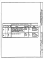
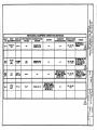
21. Sheets A-601 and A-602: Sheets in their entirety have been reissued; revisions are as
follows, but not limited to: Additional column has been added to schedule calling
out the door frame depth; The jamb width of frame 'type 3' has been changed to 2";
Frame 'type 4' has been added; Remarks 9 through 12 have been added; For the
following doors remark 6 has been removed and remark 9 added: GOO1B, GOO1D,
GO1B, GO2B, G100A, G100B, G100C, G100AA, G100A1A, GlOOCA, GlOOCIA,
GlOODA, GIOIA, GIOIBA, G102A, G102BA, G103A, G104A, G105A, G105AA,
G106A, G106AA, GIO7A, GO1C, G02C, G202A, G203A, G203B, G204A, G204B,
G205A, G206A, and G207A; For the following doors remark 7 has been removed
and remark 10 added: G100A, G100B, GIO0C, GlOOAA, GIOOCA, and G107A;
All doors with a fire label rating shall receive remark 1; The following doom were
missing from the schedule and have been added: B100D1A, B1698, EEC, GO1A,
G104C, POO1C, PlOOICA; the following doors have been revised in one way or
another (please compare to door schedules in the bid set): B100A, BI ICA, B1 13A,
5
B116B, B118B, B118AA, 8118AB, B135A, B146F1, B147AA, B147BA, B147CA,
B152A, B152B, B154B, B154B1, B154C, B154C1, B158A, B158AA, B158BA,
B162F, B162DD, B162DE, 8162DF, B162GA, B162HA, B162JA, BI65A,
B169AA, B169AB, B171A, 13/ 72A, B172B, B173A, BI73B, CO1A, CO1B, COIC,
CRTA, CRTB, DE1, GOOB, GOOC, GOOD, GOOE, GO2A, G1OOBA, G104B, C1 1A,
Cl2A, C13A, POO1B, POOIC, P100A, P100B, PlOOMA (was listed as Cl2A),
P103CA, P115AA, P115EA, B210AA, B210AB, B229AA, B237A, B247A, G204A,
P211BA, P2I IEA, P212A.
22. A-603 verbal clarification: Details B3/A-603, A2/A-603, and Al/A-603, the
reference keynote pointing to the steel beam should be '051 00.A02', not `05500.A02';
At detail Bl/A-603 reference keynote '08411.A03' at aluminum frame should be
reference keynote '08520.A'; At detail C4/A-603 sheet Keynote #4 is in reference to
the dimension of the steel door frame; Detail A3/A-603 reference keynotes have
been corrected. See sketch A-3.
23. A-604 verbal clarification: Detail C4/A-604 sheet keynotes added. See sketch A-3;
At detail A3/A-604 reference keynotes have been corrected. See sketch A-3.; Detail
D1/A-604, thickness of board insulation (04810B.H) has changed from 1" to 2".
24. A-605 verbal clarification: Derails C4/A-605, E4/A-605, Bl/A-605, and D1/A-605
reference keynote '04810B.A' should be '04810B.B1.
25. A-606 verbal clarification: Details B5/A-606, C5/A-606, 134/A-606, D1/A-606, and
El /A-606, reference keynote '08411.0 should be 08110.N for steel frame.; Details
A3/A-606, B3/A-606, C3/A-606, and D3/A-606, thickness of semi-rigid blanket
insulation should be 3". Not 1.5".; Detail E3/A-606 semi-rigid blanket insulation
removed from detail.;
26. A-607 verbal clarification: Details E3/A-607 and D3/A-607 steel door frames are 10
3/4" deep, not 8 3/4".; Head detail #68 added to sheet A-607. See sketch A-4.
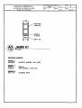
27. A-608 verbal clarification: Detail A4/A-608 thickness of semi-rigid blanket
insulation should be 3". Not I.5".; Detail C5/A-608 reference keynotes are now
corrected. See sketch A-4.; At jamb details D4/A-608, Al /A-608, and Bl/A-608
the sill below the coiling door to extend 4 1/8" beyond the face of the cmu wall. See
sketch A-4.
28. A-609 verbal clarification: Details B3/A-609, C3/A-609, A2/A-609, and B2/A-609
all cmu dimensions should call out a length of 16" not 816".; At jamb detail A5/A609 the sill below the coiling door to extend 4 1/8" beyond the face of the cmu wall.
See sketch A-4.; Jamb detail #61 added to sheet A-609. See sketch A-5.
29. Sheets A-105 and A-403: The wall between rooms BlOOG and B100.1 has been
rotated and shifted to make room for the edge of the overhead coiling door in room
B100J. New dimensions have been given. See sketch A-6 for floor plan changes,
and sketch A-7 for reflected ceiling plan changes.
30. Sheet A-307: Wall section A3/A-307 has been revised. See sketch A-8.
31. Sketch A-9: Wall type W03 added in NE comer of room B148 to create chase
behind casework for overflow drain piping.
32. A-122: The acoustical panel ceiling in the following rooms shall now be 10 %0" a.f.f.
instead of 9'-0": Masonry Office 8146B, Tool Crib B146A, Student Tool Storage
B146E, Masonry Male Changing B146F, Masonry MRR B146F1, Masn/Plurnb
WRR B154B /, Plumb MRRB154C1, Masonry/Plumb Women Changing B154B,
Plumbing Male Changing B154C. No sketch/drawing issued.
6
33. A-104: Revisions to Masonry Lab and related changing rooms. Entire sheet issued.
34. 1-103: Revisions Masonry Lab and related accessory rooms. Entire sheet issued.
35. 1-131: Revisions to Masonry Lab and related changing rooms. Entire sheet issued. .
LANDSCAPE
1. Sheet L-101: The L-101 included in the bidding documents was not the correct
version. Included in this addendum is the most recent version.
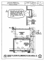
PLUMBING
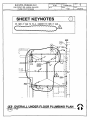
1. Sheet P-101, Underfloor Overall Plumbing Plan, see sketch P-1 for revised sanitary
sewer piping serving the Masonry Lab and the deletion of Oil Interceptor OM.
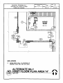
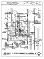
2.
Sheet P402, First Floor Plumbing Plan Area A, see sketch P-2 for revised routing of
8" OFD from Area C.
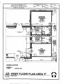
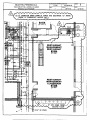
3.
Sheet P-104, First Floor Plumbing Plan Area C. Drawing has been reissued for the
new Masonry Lab, revising the natural gas piping sizes and rerouting of the 8" OFD.
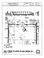
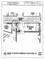
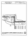
4.
Sheet P405, First Floor Plumbing Plan Area D, see sketch P-3 for revised routing of
8" rainwater conductor and overflow drain from the second floor.
5.
Sheet P-106, First Floor Plumbing Plan Area E, see sketch P4 and P-5 for revising
the sizing of the natural gas line.
Sheet P-113, Second Floor Plumbing Plan Area D, see sketch P-6 for added roof
drain and overflow drain for the Stage Area Roof and associated piping.
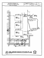
6.
7.
Sheet P401, Enlarged Kitchen Plan, see sketch P-7 for revised natural gas pipe sizes.
8.
Sheet P-601, Plumbing Schedule, see sketch P-8 for revised Plumbing Fixtures.
9.
Sheet P-606, Plumbing Isometric, see sketch P-9 for revised sanitary and sanitary
vent piping for new Masonry Lab.
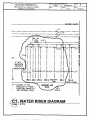
10. Sheet P-608, Water Riser Diagram, see sketch P-10 for revised water piping for new
Masonry Lab.
11. Sheet P-614, Natural Gas Riser Diagrams, Drawing has been reissued for the pipe
sizes that have been revised.
MECHANICAL
1. Sheet M-103, First Floor Mechanical Plan Area C, Drawing has been reissued for
the new Masonry Lab.
2.
Sheet M-405, Mechanical Sections, Drawing has been reissued for the new Masonry
Lab.
3.
Sheet M-602, Mechanical Schedules, see sketch M-1 for the revised Exhaust Fan
Schedule.
4.
Sheet M-603, Mechanical Schedules, see sketch M-2 for the revised Diffuser
Schedule and addition of the Air Cleaning Unit Schedule.
5.
Sheet M-604, Mechanical Schedules, see sketch M-3 for the revision to the Makeup
Air Unit Schedule.
6.
Sheet M-720, Control Diagram, added MAU-2 to Diagram, no sketch issued.
7
7. Sheet M-721, Control Diagram, Drawing deleted from the project.
ELECTRICAL
I. Sheet E-103, First Floor Lighting, Area C, no sketch provided:
a. Remove the extraneous keynote tags #3 and #4 (without leaders) shown on
the left side of Masonry Lab B146.
b. Added sheet keynote #17 tag to the two (2) type "FB" light fixtures located
within Masonry Storage, B146D.
C. Added sheet keynote #17 to read as follows: "Suspend fixtures within area
14'-0" minimum to bottom of fixture and locate up between joists.
2. Sheet E-104, First Floor Lighting, Area D: See sketch E-072010-0I for additional
sheet keynote #35 which has been added to the plans and shifted some wallmounted items to reduce conflict with rigging and stage curtains.
3. Sheet E-112, Second Floor Lighting Plan Area D: Added a 4-way light switch at the
top of the stairs within Mechanical Room #B249 on the non-hinged side of door for
control of lighting upon entering room from stairs. No sketch issued.
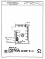
4. Sheet E-115, First Floor Power Plan Area A: See sketch E-072010-03 for location of
combination motor starters for MAU-1 and MAU-2 in electrical closet B145.
5. Sheet E-117, Masonry Lab Revisions — Adjusted layout of electrical devices,
removed electrical devices associated with previous Auto Collision Lab. Adjusted
electrical to accommodate mechanical revisions. Added devices associated with
Masonry Lab equipment. Entire drawing issued.
6. Sheet E-401, Enlarged Electrical Plans: See sketch E-072010-04 for location of
combination motor starters for MAU-1 and MAU-2 in electrical closet B145.
7. Sheet E-506, Electrical Details. Changed APS drawing number in title block to
match sheet number and removed the "E" symbol and description under the wire
legend on the drawing that was not used on this drawing. No sketch issued.
8. Sheet E-506A, Electrical Details sheet added to project. Entire drawing issued.
9. Sheet E-604, Lighting Fixture Schedule: See sketch E-072010-02 that shows the
changes to the exit signs to clarify where wireguards are to be provided.
10. Sheet E-609. Equipment Connection Schedule: See sketch E-072010-05 for removal
of equipment EF-74 thru EF-77 and MAU-3. Revised equipment MAU-2.
Additional Equipment ACS-1 thru ACS-6.
11. Sheet E-612, Panelboard Schedule PPJ: See sketch E-072010-06 for load and breaker
revisions associated with Mechanical equipment revisions_
12. Sheet E-614, Panelboard Schedule RP2: Removed circuit RP2-58 associated with
electrical devices now removed in masonry lab. Now spare breaker. No sketch
issued.
13. Sheet E-617, Panelboard Schedule GP12: Added 20A/1P breakers in spaces 34,35,
and 36 for constant circuits for stage lighting (front of house lighting) and wall
pockets shown on sheet E-506A. Entire drawing issued.
14. Sheet E-617, Panelboard Schedule GP9: Revised breaker size and load for Air
Compressor AC-1. Paneiboard Schedule GP10: Revised schedule to reflect removal
of equipment associated with previous Auto Collision Lab and the addition of
equipment associated with Masonry Lab. Entire drawing issued.
8
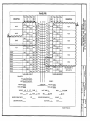
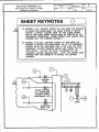
FIRE ALARM
1. Sheet F-501, Fire Alarm Details. Added interconnection to the fire alarm system for
the emergency lighting within the auditorium to be energized to 100% output and
the muting of the various sound systems during an alarm (gymnasiums, student
dining, auditorium). See sketch F-072010-01 for changes.
TECHNOLOGY
I. Sheet T-103: Masonry Lab revisions - Removed (2) 2-port data outlets from the west
wall and relocated wall mounted motion detector from the west wall to the east wall.
See sketch SK-T103-A.
END OF ADDENDUM NO. 1
9
Buchtel/Perkins Community Learning Center
OSFC Project # 55-7110-9029425
GPD - 2007271.15
Phase 3 CLC Package— Bidding Documents — July 1, 2010
1. Interior and exterior finished unit masonry appearance shall exceed the finish requirements of
ASTM C90-02, to require repair of chipped or broken units that have visible defects from a
distance of ten (10) feet under diffused permanent lighting. Repair finish texture to be similar
to unit masonry face. Sizes of chipped and broken masonry units shall not exceed V1 inch in
any direction.
2.
Interior and exterior finished unit masonry appearance shall be required to conform with
quality standards set by the approved masonry sample panels.
2.2
CONCRETE MASONRY UNITS (GREY BLOCK CMU'S) AND DECORATIVE CONCRETE
MASONRY UNITS
A.
Regional Materials: Provide CMUs that have been manufactured within 500 miles of Project site
from aggregates and cement that have been extracted, harvested, or recovered, as well as
manufactured, within 500 miles of Project site.
B.
Shapes: Provide shapes indicated and as follows:
I.
2.
3.
4.
C.
Provide special shapes for lintels, corners, jambs, sashes, movement joints, headers, bonding,
and other special conditions.
For ends of sills and caps and for similar applications that would otherwise expose unfinished
surfaces, provide units without cores or frogs and with exposed surfaces finished.
Provide special shapes for applications where shapes produced by sawing would result in
sawed surfaces being exposed to view.
Provide bull-nose units for outside corners, unless otherwise indicated.
Concrete Masonry Units (Grey Block Units): ASTM C 90-02.
1.
2.
3.
4.
Unit Corn
gth: Provide units with minimum average net-area compressive
strength
Weight
s ion: Medium weight, unless otherwise indicated.
Initial Rate of Absorption: 15 pd.
Approved Manufacturers:
a.
b.
c.
d.
e.
f.
VanPoppelen Bros; Mileau Recycled Series CMU (40% recycled postconsumer,
regional materials).
Beavertown Block Co., Inc. (1/2 preconsumer + postconsumer = 20% minimum;
regional materials).
Chas Svec, Inc. (1/2 prconsumer + postconsumer = 33% minimum; regional
materials).
Koltcz Concrete Block Co.; Staglite II (1/2 preconsumer + postconsumer = 36%
minimum; regional materials).
R.W. Sidley, Inc. (1/2 preconsumer + postconsurner = 20% minimum; regional
materials).
Medina Supply Company — Green Block (1/2 preconsumer + postconsumer = 20.8%
minimum; regional materials)
D. Decorative Concrete Masonry Units: ASTM C 90.
1.
2.
3.
4.
Unit Compressive Strength: Provide units with minimum average net-area compressive
strength of 1,900 psi.
Density r acsifieation: Medium weight.
Size (Width): Manufactured to dimensions specified in "CMUs" Paragraph.
Pattern and Texture:
UNIT MASONRY ASSEMBLIES —04810-7
APS 5-1-2010
•
/
OSFC Project # 55-7110-9029425
2.2
MANUFACTURERS
• I AL , I •
ft
A.
GPD - 2007271.15
Phase 3 CLC Package— Bidding Documents — July 1, 2010
Acceptable Manufacturers:
1.
2.
3.
4.
5.
6.
2.3
4:11
Traco
Peerless Products, Inc.
Graham
Capitol Aluminum and Glass
Wausau Window and Wall Systems
Malik° Window Systems
NX-3000 Series
1200 Series
6000 Series
325 SS
3250 Series
Model 3527
ALUMINUM WINDOWS
A.
Window Operation: Comply with functions indicated on Drawings.
B.
Window Grade: Architectural Window AW 60 or AW 80, noted in Section 1.3.
C.
Glazing: Insulated glass unit with additional hinged clear tempered glazing panel to protect blinds.
1. Vent and fixed triple glazing: Neoprene gasket; % or 1 inch insulating glass; internal EPDM
gasket; (blinds;). 1/4 inch interior lite in flexible PVC gasket in butt-hinged panel secured
with tamper-proof screws, aluminum hinge opened with a tamper proof wrench.
a.
Refer to Section 08800 for Glazing.
D.
Construction: Thermally improved.
E.
Aluminum Window Members . Aluminum extrusions not less than 0.125 thickness at any location
for main frame and sash. members or window design to incorporate multi-chamber hollow
construction in both the sash and frame utilizing euro-groove technology.
2.4
MATERIALS
A.
Aluminum extrusions: produced from commercial quality 6063-T5 alloy; free from defects impairing
strength and durability.
1. Aluminum extrusions not less than 1/8 inch thickness at any location for main frame and
sash members, or window design to incorporate multi-chamber hollow construction in both
the sash and frame utilizing euro-groove technology.
B.
Hardware as required for type of window operation and including, but not limited to the following:
1. Concealed stainless steel hinges conforming to AAMA 904-01 to rotate vent outward on
[horizontal] [vertical] axis; white bronze cam handles and. strikes conforming to AAMA 90196 and multi-point lock; stainless steel limit arm with release key.
C.
Weatherstripping: Scouted in extruded ports; double rows on sash perimeters: rigid PVC
weatherseal in one side of the vertical stiles, one flexible thermoplastic rubber bulb+flap seal in
bottom sash lift rail in contact with exterior frame sill, and pile conforming to AAMA 701-92 with
polypropylene center fm in the remaining locations.
ALUMINUM WINDOWS — 08520 - 3
APS 5-1-2010
Buchteyp
mm ii Learning Center
OSFC Project # 55-7110-9029425
1.
Manufacturers: Subject to compliance with requirements, provide products of one of the
following:
a.
b.
c.
d.
2.
b.
B.
Aacer Flooring, LLC.
Connor Sports Flooring, LLC.
Homer Flooring.
es.
Robb s S
Species and Grade:
a.
3.
4.
5.
6.
GPD - 2007271,15
Phase 3 CLC Package— Bidding Documents — July 1, 2010
Stage Thrust: Northern Hard Maple, MFMA grade, and trademarked. Provide third
and better grade.
Stage: Prime VG, Finish grade Douglas Fir or Larch. Face of each piece must present
a vertical grain appearance.
Cut: Plain sawn. For maple and vertical grain (VG) for Douglas Fir or Larch.
Thickness: 25/32 inch.
Face Width: 2-1/4 inches.
Lengths: Random-length strips complying with applicable grading rules.
Urethane Finish System: Complete solvent-based, oil-modified system of compatible components
that is recommended by finish manufacturer for application indicated,
1.
2.
VOC Content: When calculated according to 40 CFR 59, Subpart D (EPA Method 24), as
follows:
a.
Finish Coats and Floor Sealers: Not more than 350 g/L.
b.
Stains: Not more than 250 g/L.
Finish Coats: Formulated for multicoat application on wood flooring.
a.
Products: Subject to compliance with requirements, provide one of the following:
1)
2)
3)
4)
5)
3.
Basic Coatings, Inc.
BonaKemi USA Inc.
Dura Seal, Sherwin-Williams Company (The).
Ecolab Inc., Huntington Brand.
Polo-Plaz Coatings, National Coatings Company.
Floor Sealer: Pliable, penetrating type.
C. Wood Filler: Compatible with finish system components and recommended by filler and finish
manufacturers for use indicated. If required to match approved Samples, provide pigmented filler.
ACCESSORY MATERIALS
2.2
A.
Wood Underlayment: 3A" (19mm) CDX grade plywood.
B.
Vapor Retarder ASTM D 4397, polyethylene sheet not less than 6.0 mils thick.
C.
Asphalt-Saturated 15 lb. Felt ASTM D 4869, Type IL Between plywood underlayment and
finished strip flooring_
WOOD FLOORING -09640-3
APS 05-29-09
er
mmuni Le • I
OSpc Project # 55-7110-9029425
0.0
1.6
I
Ce ter
D-201 7l.5
Phase 3 CLC Package— Bidding Documents — July 1, 2010
PROJECT CONDITIONS
A. Conditioning period begins not less than seven days before sports-floor assembly installation, is
continuous through installation, and continues not less than seven days after sports-floor
installation.
1.
2.
Environmental Conditioning: Maintain an ambient temperature between 65 and 75 deg F
and relative humidity planned for building occupants, but not less than 35 percent or more
t ;'Ti 50 percent, in spaces to receive sports-floor assemblies during the conditioning period.
Wood Conditioning: Move wood components into spaces where they will be installed, no
later than beginning of the conditioning period.
a.
b.
Do not install sports-floor assemblies until wood components adjust to relative
humidity of, and are at same temperature as, spaces where they are to be installed.
Open sealed packages to allow wood components to acclimatize immediately on
moving wood components into spaces in which they will be installed.
B.
After conditioning period, maintain relative humidity and ambient temperature planned for building
occupants.
C.
Install sports-floor assemblies after other finishing operations, including painting, have been
completed.
FART 2- PRODUCTS
2.1
MANUFACTURERS
A.
Manufacturers: Subject to compliance with requirements, provide products by one of the following:
Basis of Design: Robbins Air Channel Star as manufactured by Robbins Sports Surfaces.
1.
Wood, Athletic-Flooring Assemblies:
A.acer Flooring, LLC.
Conner Sport Court, Intl.
omer Floo
Action Floor Systems
2.2
Anchored Power Sleeper
Anchored Rezill Sleeper Div.
ted Sleeper Subfloor
Action Pro Air
MAPLE FLOORING
A.
Strip Flooring: Northern hard maple (Acer saccharum), kiln dried.
1.
2.
3.
4.
5.
6.
7.
Grade: Second & Better, unless otherwise indicated; third grade for areas under stacked
portion of telescoping bleachers.
Cut: Flat grain cut.
Lengths: Nominal 15 to 96 inches complying with MFMA grading rules, unless otherwise
required for patterns indicated.
Matching: Tongue and groove, and end matched.
Backs: Channeled (kerfed) for stress relief.
Thickness: 25/32 inch.
Face Width: 2-1/4 inches
WOOD ATHLETIC-FLOORING ASSEMBLIES - 09642-3
APS 05-06-09
uchtcl/Perkins Community
OSFC Project # 55-7110-9029425
3.6
Center
GPD - 2007271.15
Phase 3 CLC Package– Bidding Documents – July 1, 2010
PAINT SCHEDULE
A.
Items to be painted include, but are not limited to the following.
1.
Interior
Hardwood trim: Stain.
a.
Steel doors and frames: Paint.
b.
Concrete and Masonry (walls): Paint.
c.
Gypsum board (walls): Paint.
d.
Gypsum board. (ceilings and soffits): Paint.
e.
Vinyl (floor): Paint.
f.
All miscellaneous steel items: Paint.
g.
All mechanical and electrical items under paragraph 3.3 of this section: Paint.
h.
i.
Pipe and Tube Railings . Paint.
Exposed steel structure as noted in room finish schedule: Paint.
j.
Concrete floors: Paint (where specified).
k.
2.
Exterior
Hollow metal doors and frames: Paint.
a.
Lintels: Paint.
b.
c.
Exterior plaster soffits: Paint.
Bollards and Corner Protector Steel: Paint.
d.
Gas meter setting, excluding prefinished iternc- Paint.
e.
COLOR SCHEDULE FOLLOWS
3.7
A.
General: Provide products from one of the specified manufacturers in sections 2.3 and 2.4. Match
colors to color schedule.
B.
09900 Painting Schedule
Color Name
Product Manufacturer Color Number
ICI
A0077
Ivory
Fresco
P-1
A2016
ICI
Dark Secret
P-2
ICI
A0057
P-3
Crisp Linen
ICI
A1831
P4
Old. Monterey
P-5
ICI
A1392
Blazer Blue
ICI
A1382
P-6
Atwood Lakes
ICI
A0987
- P-7
Inchworm
_
ICI
A1616
P-8
Stage Fright
_
A0683
P-9
ICI
Glorious
A0514
P-10
ICI
Woodley
_
P-11
ICI
A0291
Crimson Red
P-12
ICI
—
-......._
: II
ICI
TED —
P-13
P-14
TED
ICI
TBD
_
ICI
P45
A1768
Highland PJairi
3.8
,
Remarks
Field wall color
Black
White
Gray
Blue
Lt. Blue
Green
Purple
Yellow
Orange
Red
a
–
To match red brick
To match buff brick
Interior metal doors
(AAG NOTE: EXAMPLE ONLY. MODIFY PER PROJECT. USE SCHEDULE]
PAINTING - 09900 - 18
APS 08-20-09
ILJ en
Bu chtel/P :I 4 Co I_
OSFC Project # 55-7110-9029425
0 271.
Phase 3 CLC Package— Bidding Documents — July 1, 2010
C. Anchors and Inserts: Use nonferrous metal or hot-clipped galvanized anchors and inserts for
exterior installations and elsewhere as required for corrosion resistance. Furnish inserts, as required,
to be set into masonry work.
1.
2.
2.2
Letters to be offset, stud mounted.
Flat cut metal letters to have tapped holes for stud insertion, and are to be stud welded.
DIMENSIONAL LETTERS
A.
Cut Metal Letters: Form individual letters by cut metal. Produce characters with smooth, flat faces,
sharp corners, and precisely formed lines and profiles. Comply with requirements specified for
finish, style and size.
B.
Text: As indicated on drawings.
C.
Fon
D.
Size: As indicated on drawings.
E.
Thickness: 1/4 inch.
2.3
FINISH
A. General: Comply with NAAMA "Metal Finishes Manual" for finich designations and applications
recommendations.
B.
2.4
All exposed aluminum surfaces shall receive a baked-enamel finish
1.
Color: Dark Bronze.
APPROVED MANUFACTURERS
A.
Manufacturers:
1.
2.
3.
4.
5.
A.R.K. Ramos;
ANDCO Industries Corp.
ASI Modulex;
VOMAR Products, Inc.
Gemini
PART 3- EXECUTION
INSTALLATION
3.1
A.
Securely install in location indicated on the drawings in accordance with manufacturer's written
instructions and recommendations.
1.
2.
Install letters level, plumb and at heights indicated, with surfaces free from distortion or other
defects in appearance.
Mount letters flush with wall surface.
EXTERIOR IDENTIFICATION LETTER SIGNAGE - 10432 -2
APS 05-29-09
Buchtel/Perkins Community Learning Center
OSFC Project #55-7110-9029425
b.
2.
Finish: Match lockers.
Continuous Sloping Tops: Fabricated from cold-rolled steel sheet, manufacturer's standard
thickness, but not less than 0.0329 inch thick.
a.
Provide at corridors only:
1)
2)
b.
Sloped top comer fillers, mitered.
Flat Finished Tops: Fabricated from cold roiled steel sheet, manufacturer's standard
thickness, but not less than 0.0528 inches thick.
a.
Provide at classrooms only.
4.
5.
Recess Trim: Fabricated from 0.0428-inch- thick, cold-rolled steel sheet.
Filler Panels: Fabricated from cold-rolled steel sheet, manufacturer's standard thickness, but
not less than 0.0329 inch thick.
Boxed Finished End Panels: Fabricated from 0.0528-inch- thick, cold-rolled steel sheet.
Numbering Plates: Equip each metal locker with identification plate.
a.
b.
Numbers shall commence with one (1) and continue consecutively from left to right
(facing the lockers) for single tier lockers.
At double tier lockers, numbers shall progress from left to right (facing the lockers)
with odd numbers on top tier and even numbers on the bottom tier.
Finish: Baked enamel.
1.
2.4
Closures: Hipped-end type.
Retain first subparagraph below where two runs of metal lockers meet at right
angles.
3.
6.
7.
K.
GPD - 2007271.15
Phase 3 CLC Package— Bidding Documents — July 1, 2010
Color(s): Match architects paint colors.
ALL-WELDED ATHLETIC METAL LOCKERS
A.
Products:
1.
All-Welded, Athletic Metal Lockers:
a.
b.
c.
d.
e.
f.
Lyon Workspace Products; Integrated Frame All-Welded Lockers.
Penco Products, Inc., Subsidiary of Vesper Corporation; All-Welded Lockers.
Republic Storage Systems Company; All-Welded Ventilated Lockers.
ASI Storage Solutions; Competitor Collection.
Superior Lockers; fully framed, all welded athletic lockers.
Pinnacle Storage Products; TA-50 welded lockers.
B.
Locker Arrangement: Single tier.
C.
Locker Size:
1.
[Type 53: 12" wide x12" deep x 60" high, single tier. Refer to drawings.
8" 'de
" d
61"'
2.
th.e6
Refer to drawings.
[Type 71: 12" wi e X15" deep x 72" high, single tier. Refer to drawings.
3.
METAL LOCKERS -10505-6
APS 05-13-2010
auchtel/Perkins Community Learning Center
OSFC Project # 55-7110-9029425
E.
Clinic Refrigerator/Freezer (S4): Top freezer; 15 Cu. ft. capacity; minimum of two fresh food shelves;
two crisp drawers; white:
1.
2.
3.
F.
GPD - 2007271.15
Phase 3 CLC Package- Bidding Documents - July 1, 2010
Frigidaire, Model FRT15B3A
Kenmore, Model 64522
GE, Model GTR16BBSRWW
Clothes Washer (S5): Washer: 3.5 cu. ft. top loading super capacity washer with stainless steel
wash basket, 17 wash cycles, five wash/spin speed combinations and four levels.
1.
2.
3.
GE, Model WTRR4170EWW (white) Basis of Design.
Maytag (white) MTW5800TW.
Kenmore (white) 28522.
G. Clothes Dryer (S6): 7.0 cu. ft. super capacity with stainless steel drum, four heat selections, eight
dry cycles, auto dry thermostat, wrinkle care extended tumble, and adjustable volume on an end-ofcycle signal
1.
2.
3.
GE, Model DRSR483EDWW (white) Basis of Design.
Maytag to match Basis of Design (white) MED5801TW.
Kenmore to match Basis of Design (white) 68622.
H. Freestanding Range/Oven (Si): 30-inch electric freestanding range with four coil burners; chrome
drip bowls; porcelain enamel on steel cooktop surface; lift-up cooktop with support rod; selfcleaning oven; extra-large oven door window; storage drawer; white.
Frigidaire, Model FEF354GS
1.
Kenmore, Model 94212
2.
GE, Model JBP24draww
3.
Whirlpool, Model RF263LXTQ
4.
1. Front loading clothes washer (58): Washer 4.0 cu. ft. king size capacity front load washer, Energy
Star compliant, quiet package, stainless steel wash basket, with power cord and related
appurtenances for a full installation.
GE, Model WCVH6800j (white)
1.
2.
Maytag, MFW9700S (white)
Kenmore, 4996 (white)
3.
J.
Front-loading Clothes Myer (59): 7.0 cu. ft. super capacity electric dryer, Energy Star compliant,
front loading, quiet package, with power cord.
GE, Model DCVH680EJWW (white)
1.
Maytag, MED9700SQ (white)
2.
3.
Kenmore, 87872 (white)
K. Copy/Work Room under-counter Refrigerator (S10): 5.8 cu. ft. compact refrigerator, adjustable
temperature controls, push button defrost control, adjustable shelves, freezer compartment.
Dimensions: 33"h x 23 xh"w x 24-25"cl. (must install under ADA counter height).
Kenmore 95872, (white) Basis of Design
1.
Maytag to match Basis of Design
2.
GE to match Basis of Design
3.
L.
Science Prep Room Dishwasher (S11): Built-in dishwasher, Energy Star compliant, stainless
steel tab, quiet package, hard food disposer, ADA compliant.
1.
GE, Model GLD4408RWW (white)
Frigidaire, Model. FDB2410HI (white)
2.
3.
Whirlpool, Model GU3/00XTV(white)
• •
APS 09-02-09
13.1.10glaeLki
r ' s Community Learning Center
OSFC Project # 55-7110-9029425
GPD - 2007271.15
Phase 3 CLC Package— Bidding Documents — July 1, 2010
ing excessive deterioration or failure of system components when the system is subjected to normal
use. Repair or replacement shall include all costs associated with verifying failures, removal of deteriorated or defective products, replacement, testing, transportation, travel, and other expenses related to
corrective measures.
1.
The warranty period shall be five years from the date of Project Completion Date.
PART 2- PRODUCTS
2.1
PRODUCTS, GENERAL
A.
2.2
Refer to section 01600— Product Requirements.
MANUFACTURERS
A. Basis of Design: Design is based on "Mecho/5 Th wide bracket" shade system manufactured by
MechoShade®, Long Island City, NY www.mechoshade.com , and as follows:
1.
2.
3.
4.
5.
B.
2.3
Mounting method: Mount directly to structural components as indicated on Drawings.
Provide valance to conceal motorized components.
'es 1550
Shade Cloth:
Eco
Control system
Direction of Roll: Reverse • cm ba
Additional Manufacturers:
1.
Draper Shade & Screen Co., Inc
Website: vvww.draperinc.com
2.
Lister Motorized Blinds and Shades
Website: www.listerupbolsterv.com
3.
Inside Outfitters: SOS Roller Shades
Website: www.insideoutfitters.com
ROLLER SHADE FABRICATION
A.
Product Description: Roller shade consisting of a roller, a means of supporting the roller, a flexible
sheet or band of material carried by the roller, a means of attaching the material to the roller, a
bottom bar, and an operating mechanism that lilts and. lowers the shade.
B.
Concealed Components: Non-corrodible or corrosion-resistant-coated materials.
1.
C.
Lifting Mechanism: With permanently lubricated moving parts.
Unit Sizes: Obtain units fabricated in sizes to fill window and other openings as follows, measured
at 74 deg F:
1. Shade Units Installed Between (inside) Jambs: Edge of shade not more than Vs inch from
face of jamb. Length equal to head to sill dimension of opening in which each shade is
installed.
ROLLER WINDOW SHADES — 12494 - 3
APS 12-01-08
B-1S
/ hte1/PerkinLCommunitv Learning Center
OSFC Project # 55-7110-9029425
GPD - ;007271.15
Phase 3 CLC Package— Bidding Documents — July 1, 2010
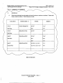
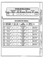
PART 4- SCHEDULE OF OPENINGS
4.1
SCHEDULE
A.
Provide one roller shade at each window or band of continuous windows as indicated. Shades shall
break at window mullions. Verify dimensions in field.
LOCATION
Area E
ROOM NAME / #
Student Dining B162
i- First Floor
Area D
WIDTH
HEIGHT
(6) 6'-6"
6'4"
5'-0"
Media Room P102
(5) 6'-6"
11'-4"
Media Room B169
(5) 6'-6"
1P-4"
8'-4"
6'4"
First Floor
Area D
First Floor
Area D
Second Floor
Media Room B169
(2) 9'-8 'A", (1) 14'-7"
(2) 15'-6", (1) 10'-3 1/3"
END OF SECTION
ROLLER WINDOW SHADES —12494-5
APS 12-01-08
9'-Z"
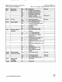
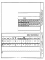
Buch tel/PerIcins Community Learning Center OSFC Project #55-7110-9029425
Room
B146
B146A
Item
Room Name
Masonry Lab
11.
1
GPD Project #2007271.15
Phase 3 - CLC Package - Bidding Documents - July 1, 2010
Qnty. Description
4
32 gallon waste container
32 gallon recycling container
1
Workbench with steel top
2
Flammable storage cabinet
Student work table
Portable visual display board
24"d Storage shelving
11 Heavy-duty
storage cabinet
3
B1413
6
B146C
01
1
02
2
K19
I
R4
1
B146D
B146E
Ki4
22
W2
1
Ki
1
B146F
B146FI
Loose Furnishings Room Schedule
Remarks
1
With (4) vice
Sec note I
17"-18" high student chair
Teacher and Administrative desk "L" shaped steel desk
Task h . ht
Wastebasket
Bee/cling container - small
6"w x 12"d x 29"-30"h steel
bookcase
17"-18" high student chair
17"-18" high student chair
Student desk - 26"-32" height
adjustable desk
Combination chair and desk unit
Administrative/teacher desk
2-drawer vertical file
Single student computer table - 30"cl
x 36"w
Two student computer table - 30"d
x 60"w
Wastebasket
Recycling container - small
Pencil sharpener
Flag, classroom with staff,
16"x24"
241cl Storage shelving
See note 1
24"d Storage shelving
18"cl Storage shelving
48"w x 22"d x 66"h tool cabinet
Wastebasket
See note 1
See note 1
Wastebasket
12900
1 of I
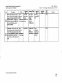
Buchtel/Perkins Community Learning
Center
OSFC Project #55-7110-9029425
Item
Description
Heavy-duty tall storage cabinet 48"w x 24"d x 82"h all welded 14
gauge steel storage cabinet with 4
Ms_ adjustable shelves, 4" high legs,
wio locking, shelf capacity 800-1400
lbs. per shelf, baked enamel or
power coat finish.
Workbench - 30-34"d x 72"w 3036"h adjustable height workbench,
/ 3/4" thick 12-gauge heavy-duty
Ms_ steel top, adjustable steel channel
W 11 legs with levelers, welded steel
cross members, with stringer and
shelf.
GPD - 2007271.15
Phase 3 - CLC Package - Bidding Documents - 07-01-10
Approved
Mfgr. 1
To be
Lyon 1120
selected
Heavy Duty
from
Storage
manufacture Cabinet Full
r's full range Height
Approved Mf'gr.
Approved
2
Mfgr. 3
Quantum
Cisco-Eagle
Heavy-Duty
Storage QSC3I5
Storage
Cabinet,
Standard
Configuration
4o be
Lyon 2525A
selected
from
manufacture
r's full range
Stackbin 3505
Series
Workbench
with steel top
Finish
Penco
Adjustable
height work
bench with
steel top
Approved
Mfgr. 4
Bid
Pkg.
12D
Remarks
12D
Loose Furnishings Item Schedule
12900
1 of 1
Bu chtel/Perkins Community Learning Center
OSpc Project # 55-7110-9029425 GPD - 2007271.15
Phase 3 CLC Package— Bidding Documents — July 1, 2010
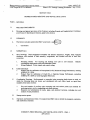
SECTION 15562
INDIRECT-FIRED HEATING AND VENTILATING UNITS
PART 1- GENERAL
1.1
RELATED DOCUMENTS
A.
1.2
Drawings and general provisions of the Contract, including General and Supplementary Conditions
and Division 01 Specification Sections, apply to this Section.
SUMMARY
A.
This Section includes indirect-fired H&V units MAU-1 an
1.
1.3
Gas furnace.
SUBMITTALS
A. Shop Drawings: Detail equipment assemblies and indicate dimensions, weights, loads, required
clearances, and methods of field assembly, components, and location and size of each field
connection.
1.
2.
B.
Mounting Details: For securing and flashing roof curb to roof structure. Indicate
coordinating requirements with roof membrane system.
Wiring Diagrams: Power, signal, and control wiring.
LEED Submittals:
1.
Product Data for verification of Prerequisite EA-P2, Minimum Energy Performance, meeting
ASHRAE 90.1 2004.
2.
Product Data for verification of Credit EA-1, Optimize Energy Performance, exceeding
ASHRAE 90.1 2004, by achieving higher efficiencies.
C. Coordination Drawings: Roof-mounted or suspended units mounting details drawn to scale, on
which the following items are shown and coordinated with each other, based on input from
installers of the items involved:
I.
2.
Size and location of roof-top units mounting rails and anchor points and methods for
anchoring units to curb or suspending units from structure.
Required roof penetrations for ducts, pipes, and electrical raceways, including size and
location of each penetration.
D.
Startup service reports.
E.
Operation and Maintenance Data: For indirect-fired H&V units to include in emergency, operation,
and maintenance manuals.
INDIRECT -FIRED HEATING AND VENTILATING UNITS -15562-1
APS 4-30-10
uh
OSFC Project # 55-7110-9029425
1111
b.
c.
d.
e.
2.
PD 107
.1
Phase 3 CLC Package- Bidding Documents - July 1, 2010
Nexans
Cerrowire
Southwire
Encore Wire
AMP Incorporated.
General Signal; 0-Z/Gedney Unit.
Square D Co.; Anderson
Ilsco
Burndy
Modular Wiring Systems
a.
b.
c.
2.2
4 •
Connectors for Wires and Cables:
a.
b.
c.
d.
e.
3.
011
Cooper Lighting "MWS"
Lithonia Wiring Systems "Reloc"
Electro - Connect Wiring
BUILDING WIRES AND CABLES
A.
0L83 listed building wires and cables with conductor material, insulation type, cable construction,
and rating as specified in Part 3 "Wire and Insulation Applications" Article.
B.
Rubber Insulation Material: Comply with NEMA WC 3.
C.
Thermoplastic Insulation Material: Comply with NEMA WC 5.
D.
Cross-Linked Polyethylene Insulation Material: Comply with NEMA WC 7.
E.
Ethylene Propylene Rubber Insulation Material: Comply with NEMA WC 8.
F.
Conductor Material: 98 % conductivity, annealed Copper.
1.
Use of aluminum wire or conductors is not permitted.
G.
Stranding: Class C. stranded conductor for No. 10 AWG and smaller; Class C, stranded conductor for
larger than No. 10 AWG.
H.
Minimum conductor size for power and lighting branch circuits shall be #12 awg.
1.
For 120 V circuits with homerun over 75 lineal feet, minimum wire size shall be #10 aWg.
I.
Use of MC cable is not permitted. (Exception - lighting fixture whips above ceiling of 6 ft. or less are
permissible.)
1.
Use of Modular Wiring Systems for lighting branch circuits may be used in lieu of conduit and wire
where permitted by Code and for concealed use only, except for homeruns to panelboards and
switch drops.
1.
2.
MWS shall be rated for 20 amp circuits, be UL listed, with pin and socket interlocking
contacts.
Conductors shall be #12 awg, THHN, 600 V, 90 deg C, copper with a separate neutral for each
phase conductor.
CONDUCTORS AND CABLES - 16120 - 2
APS 06-15-10
B
et P rkin I it II um
Of
OSFC Project # 55-7110-9029425
D- P0 7.15
Phase 3 CLC Package- Bidding Documents - July 1, 2010
F.
Seal around cables penetrating fire-rated elements according to Division 7 Section "Firestopping."
G.
Identify wires and cables according to Division 16 Section "Electrical Identification."
H.
All multiwire branch circuits shall not be permitted to share a neutral conductor.
I.
Color code conductors per voltage. See Section 16075.
3.4
CONNECTIONS
A.
Conductor Splices: Not permitted unless specifically noted on construction drawings.
B.
Wiring at Outlets: Install conductor at each outlet, with at least 12 inches (300 mm) of slack.
C.
Connect outlets and components to wiring and to ground as indicated and instructed by
manufacturer.
D.
Tighten electrical connectors and terminals according to manufacturer's published torquetightening values. If manufacturer's torque values are not indicated, use those specified in UL 486A
and UL 486B.
FIELD QUALITY CONTROL
3.5
A.
Testing: On installation of wires and cables and before electrical circuitry has been energized,
demonstrate product capability and compliance with requirements.
1.
B.
Procedures: Perform each visual and mechanical inspection and electrical test stated in
NETA ATS, Section 7.3.1. Certify compliance with test parameters.
Correct malfunctioning conductors and cables at Project site, where possible, and retest to
demonstrate compliance; otherwise, remove and replace with new units and retest.
END OF SECTION
CONDUCTORS AND CABLES- 16120 - 4
APS 06-15-10
el
om
OSFC Project # 55-7110-9029425
00727
Phase 3 CLC Package- Bidding Documents - July 1, 2010
C.
Comply with NFPA 70.
D.
High Efficiency Dry-Type Transformers: Department of Energy CSL-3.
E.
Sound Levels: NAME ST 1-4 and ANSI C89.1.
1.4
DELIVERY, STORAGE, AND HANDLING
A. Temporary Heating: Apply temporary heat according to manufacturer's written instructions
within the enclosure of each ventilated-type unit throughout periods during which equipment is
not energized and is not in a space that is continuously under normal control of temperature and
humidity.
PART 2- PRODUCTS
MANUFACTURERS
2.1
A.
Manufacturers: Subject to compliance with requirements, provide transformers by one the
following:
1.
2.
3.
4.
5.
6.
Cutler-Hammer/Eaton Corp.
GE Electrical Distribution & Control.
Siemens Energy & Automation, Inc.
Square D; Groupe Schneider.
ACME Electric, Transformer Division.
Powersmiths International Corp.
TRANSFORMERS, GENERAL
2.2
A.
Description: Factory-assembled and -tested, air-cooled units of types specified, designed for 60-Hz
service.
B.
Cures: Grain-oriented, nonaging silicon steel.
C.
Coils: Continuous windings without splices, except for taps.
1.
2.
Internal Coil Connections: Brazed or pressure type.
Coil Material: Copper or aluminum.
D.
Enclosure: Class complies with NEMA 250 for the environment in which installed.
E.
Sound-Level: NEMA ST 1-4 and ANSI C89.1 standard sound levels when factory tested according to
IEEE C57.12.91.
F.
Core and coil assembly shall be mounted on vibration pads and bolted to the enclosure.
G.
No metal-to-metal contact between the core, coil, and the enclosure.
IL
KVA rating shall be as shown on drawings.
DRY-TYPE TRANSFORMER - 16461 - 2
APS 04-30-10
ct
i o l i t Le • el
OSPC Project # 55-7110-9029425
2.3
'
_ 0
71
Phase 3 CLC Package- Bidding Documents - July 1, 2010
HIGH EFFICIENCY DRY-TYPE DISTRIBUTION POWER TRANSFORMERS (CSL-3)
Comply with NEMA sr2o and list and label as complying with UL 1561.
A.
B.
Cores: Common core insulation transformer built to NEMA ST20.
C.
Windings: One coil per phase in primary and secondary.
D.
Enclosure: Indoor, gravity ventilated.
1.
Core and coil shall be encapsulated with resin compound sealing out moisture and air.
Insulation Class: 185 or 220 deg C class for transformers 15 kVA or smaller; 220 deg C class for
transformers larger than 15 kVA.
E.
1.
2.
Rated Temperature Rise: 150 deg C maximum rise above 40 deg C, for 220 deg C class
insulation; 115 deg C maximum rise for 185 deg C class insulation.
Temperature rise on transformer case not to exceed 35 deg C rise over ambient at full load.
Taps: For transformers 3 kVA and larger, full-capacity taps in high-voltage windings are as follows:
F.
1.
2.
3.
4.
G.
Taps, 3 through 25 kVA: Two 5-percent taps below rated high voltage.
Taps, 3 through 10 kVA: Two 5-percent taps below rated high voltage.
Taps, 15 through 500 kVA: Six 2.5-percent taps, 2 above and 4 below rated high voltage.
Taps, 750 kVA and Above: Four 2.5-percent taps, 2 above and 2 below rated high voltage.
Energy Efficiency for Transformers Rated 15 kVA and Larger:
1.
2.
Complying with NEMA ST20 efficiency levels.
Tested according to NEMA NP 2.
H. K-Factor Rating: Transformers indicated to be K-factor rated (K-7 minimum) are listed to comply
with UL 1561 requirements for nonsinusoidal load current handling capability to the degree
defined by the designated K-factor.
1.
2.
Electrostatic Shielding: Each winding is independently single shielded with a full-width copper
electrostatic shield arranged to minimize interwinding capacitance.
I.
1.
2.
3.
4.
5.
J.
Transformer design prevents overheating when carrying full load with harmonic content
corresponding to the designated K-factor.
Nameplate states the designated K-factor of the transformer.
K.
Coil leads and terminal strips are arranged to minimize capacitive coupling between input
and output connections.
Shield Terminal: Separate; marked "Shield" for grounding connection.
Capacitance: Shield limits capacitance between primary and secondary to a maximum of 33
picofarads over a frequency range of 20 Hz to 1 MHz.
Common-Mode Noise Attenuation: Minus 120 dB minimum, 0.5 to 1.5 kHz; minus 65 dB
minimum, 1.5 to 100 kHz.
Normal-Mode Noise Attenuation: Minus 52 dB minimum, 1.5 to 10 kHz.
Wall-Mounting Brackets: Manufacturer's standard brackets for transformers up to 75 kVA.
Fungus Proofing: Permanent fungicidal treatment for coil and core.
DRY-TYPE TRANSFORMER -16461-3
APS 04-30-10
PD - 2 0
1
Phase 3 CLC Package- Bidding Documents - July 1, 2010
erk
•I•
• 111 -
OSFC Project # 55-7110-9029425
L
200% rated neutral 60 Hz, 10kV BIL
M.
Maximum No loads losses and minimum efficiency shall comply with the following when tested per
NEMA TP-2:
Losses and Efficiencies
Maximum No Load Losses
Efficiency at 1/6 Load
15
60 watt
97.3
30
100 watt
97.6
45
130 watt
97.9
75
180 watt
98.2
112.5
265 watt
98.4
150
340 watt
98.5
225
460 watt
98.6
300
565 watt
500
860 watt
98.8
750
1220 watt
98.9
.
_.
98.7
CONTROL AND SIGNAL TRANSFORMERS
2.4
A.
Units comply with NEMA ST 1 and are listed and labeled as complying with UL 506.
B.
Ratings: Continuous duty. If rating is not indicated, provide capacity exceeding peak load by 50
percent minimum.
C.
Description: Self-cooled, 2 windings.
2.5
FINISHES
A.
2.6
KVA Size
Indoor Units: Manufacturer's standard paint over corrosion-resistant pretreatment and primer.
IDENTIFICATION DEVICES
A. Nameplates: Engraved, laminated-plastic or metal nameplate for each distribution transformer,
mounted with corrosion-resistant screws. Nameplates and label products are specified in Division
16 Section "Identification for Electrical Systems."
DRY-TYPE TRANSFORMER - 16461 -4
APS 04-30-10
Buchtel/Perkins Community Learning Center
OSFC Project # 55-7110-9029425
GPD - 2007271.15
Phase 3 CLC Package— Bidding Documents — July 20, 2010
SECTION 16555
STAGE LIGHTING
PART 1- GENERAL
1.1
RELATED DOCUMENTS
A.
Drawings and general provisions of the Contract, including General and Supplementary Conditions
and Division 1 Specification Sections, apply to this Section.
1.2
SUMMARY
A.
1.3
This Section includes equipment for stage lighting systems including fixtures, lamps, dimmers,
controls, cabinets, and distribution components.
SUBMITTALS
A.
Product Data: For each type of product indicated.
B. Shop Drawings: Show fabrication and installation details for dimmer racks showing arrangements,
characteristics, and circuit assignments of various modules. Include elevation views of front panels
indicating devices and controls. Include illustrations and dimensioned outline drawings.
1.
2.
C.
Wiring and Riser Diagrams: Power, signal, and control wiring. Show connections and
circuit and channel assignments.
Equipment Legend: Show a unified system of designations for lighting instruments, panels,
dimmers, circuits, and equipment.
Qualification Data: For Installer and manufacturer.
D. Coordination Drawings: Floor plans showing dimensioned layout, required working clearances,
and required area above and around dimming equipment where piping and ducts are prohibited.
Show rack layout and relationships between components and adjacent structural and mechanical
elements.
E. Operation and Maintenance Data: For fixtures, distribution components, software operating
manuals and controls to include in emergency, operation, and maintenance manuals. In addition to
items specified in Division 1 Section "Closeout Procedures," include the following:
I.
Control-Console Introduction:
a.
b.
c.
d.
e.
2.
Descriptions of controls and features.
Software instruction manuals.
Setup requirements for unit and related equipment.
Default settings.
Maintenance procedures and schedules.
Control-Console Operation:
STAGE LIGHTING - 16555 -1
APS 11-12-09
GPD - 2007271.15
iluchtel/Perkins Community Learning Center Phase 3 CLC Package— Bidding Documents — July 20, 2010
OSFC Project # 55-7110-9029425 a.
b.
c.
d.
e.
f.
g.
h.
i.
j.
3.
Dimmer Panel:
a.
b.
c.
d.
e.
f.
g.
4.
5.
Elementary on-off operation.
How to set cues manually.
How to patch dimmer to channels electronically.
How to operate two-scene presets manually.
How to operate fundamental memory.
How to set and record simple cues.
How to recall, playback, and revise cues and scenes.
How to use sub-masters, split cues, store and recall programs, set up special effects,
and print out cues.
How to set up and run system for a typical event or performance.
How to get help.
Descriptions of features, functions, and safety and security precautions.
Descriptions of dimmer module features, dipswitches, non-dim functions, and racking
systems.
How to check loads against dimmer capacity ratings.
How to set basic power-in and power-out connections.
Basic maintenance requirements including need for qualified electrician for internal
maintenance; basic maintenance schedule; techniques for keeping terminals properly
tightened, filter screens clean, and overheat sensors checked; and techniques for
performing other required servicing.
How to get help.
Description of warranty.
System Troubleshooting: Procedures for common software, programming, control console,
dimmer bank, and distribution system problems; include information on how to get help.
Instruct the owner in the proper usage of each type stage lighting fixtures including relamping procedures.
QUALITY ASSURANCE
1.4
A.
Installer Qualifications: An employer of workers trained and approved by manufacturer.
B.
Dimming Equipment Manufacturer Qualifications: The system manufacturer shall provide
emergency maintenance repair support within 24 hours maximum response time and shall provide a
24 hour technical service contact number.
C.
Electrical Components, Devices, and Accessories: Listed and labeled as defined in NFPA 70,
Article 100, by a testing agency acceptable to authorities having jurisdiction, and marked for
intended use.
D.
Comply with NECA 1.
E.
Comply with NFPA 70.
EXTRA MATERIALS
1.5
A.
Furnish extra materials described below that match products installed and that are packaged with
protective covering for storage and identified with labels describing contents.
1.
Dimmer Modules — (1) Additional dual module.
STAGE LIGHTING -16555-2
APS 11-12-09
GPD - 2007271.15
Buchtel/Perkins Community Learning Center OSFC Project # 55-7110-9029425
Phase 3 CLC Package— Bidding Documents — July 20, 2010
2.
Lamps: One for every 10 of each ANSI C78 Series, type, and rating installed. Furnish at
least one of each type.
PART 2- PRODUCTS
2.1
MANUFACTURERS
A. It is the intent of this specification to establish a level of performance based on standards set by
USITT and standard stage lighting practice. Manufacturers offering multiple level of products shall
provide those products that meet the maximum requirement of the specification. Determination of
acceptability shall be at the sole discretion of the architect or his/her representative.
1.
2.2
Manufacturers: Subject to compliance with requirements, provide products by one of the
manufacturers specified. Electronic Theatre Controls (ETC) was used as Basis of Design.
LIGHTING FIXTURES AND ACCESSORIES
A.
Manufacturers:
1.
2.
3.
4.
5.
B.
General Lighting Fixture and Accessory Requirements:
1.
2.
3.
4.
5.
6.
7.
8.
9.
HI
11.
12.
13.
C.
Strand Lighting.
Electronic Theatre Controls (ETC).
Leviton Colortran.
Lighting & Electronics.
Altman Stage Lighting.
Listed under UL 1573.
Fixtures: Equipped with pigtail, yoke with pipe C- clamp, safety cable, and color filter
holder.
Metal Parts: Free of burrs, sharp corners, and edges.
Sheet Metal Components: Steel, unless otherwise indicated. Form and support to prevent
warping and sagging.
Fixture Doors and Their Internal Access: Smooth operating, free of light leakage under
operating conditions, and arranged to permit re-lamping without use of tools. Doors, lenses,
diffusers, and other pieces arranged to prevent accidental falling during re-lamping and when
secured in operating position.
Pigtail: Factory wired, 36-inch-long, 3-wire cord and stage pin connector assembly
(grounded stage pin) with cord encased in woven fiberglass or silicone tubing.
Lamp Sockets: Re-lamp without disturbing alignment or focus adjustment.
Fixture Ventilation Openings: Baffled against light leaks.
Fixture Operating Controls and Handles: Thermally insulated.
Lenses: Borosilicate glass in silicone mountings.
Framing Shutters: Stainless steel, four way; with each blade in a separate plane under
adjustable tension mounting. Blades adjust plus or minus 30 degrees of rotation in gate, for
120-degree-minimum total angular rotation between adjacent blades.
Color Filter Frame Holder: Attached to front of fixture.
Fixture Yoke: Rigid metal arranged for vertical aiming of unit and equipped with T-bolt or
hand screw to lock alignment.
Ellipsoidal Spotlights: Fixtures with an elliptical reflector mounted in a fixed relationship to the
lamp.
STAGE LIGHTING -16555-3
APS 11-12-09
OPD - 2007271.15
_auchteUPerkins Communi_W Learning Center Phase 3 CLC Package— Bidding Documents — July 20, 2010
OSFC Project 55-7110-9029425
1.
2.
3.
4.
Lamp Rating: 575W, 120V, med. 2 pin 2000 hour.
Cast Aluminum Housing
Color frame 8c safety cable: one for each fixture.
Provide the following:
• (16) - 26' Ellipsoidal Spotlight
• (12) - 36° Ellipsoidal Spotlight
D.
Fresnel Lens Spotlights: Over Stage
1.
Lamp Rating: 575 W, 120 V, med. 2 pin, 2000 hour.
2.
Lens: 6 inch (152 min).
Color frame & safety cable: one for each fixture.
3.
Provide the following:
4.
• (20) PAR-nel/or Rama Fresnel
E.
Border lights: Over stage.
1.
2.
3.
4.
5.
F.
Cyclorama Lights
1.
2.
3.
4.
5.
G.
6' ft. x 3 circuits with red, green, and blue 50 degree spread roundels.
Lamp rating: 300 W, 120 V. (Provide Q250 Par 38/FL lamps)
12 Color frames per unit & safety cables: two for each fixture.
Hanging hardware & floor trunions.
Provide the following:
• (4) R40 Bordedight (12 lamp / 3 circuit)
3 Cell X 3 Circuit Cyclorama Wash Light
Lamp rating — 300 watt to 2000 watt per cell (provide with I000Watt FCM Lamps).
Color frame: One per cell
Safety cable: One per fixture
Provide the following:
• (4) - #6571-3 L&E 3-Cell Cyc Lights
Stage Work Lights
1.
2.
3.
4.
5.
6.
Single Cell general wash light'
Safety Glass Lens
Lamp — 575w UL/CL — FLIC/LL
Connector shall be L5-20/C Twistlock Connector
Safety Cable — One per fixture
Provide the following:
• (6) — L&E Worklight
ACCESSORIES
2.3
A.
Provide the following:
• (6) 25ft 12/3 SO Stage extension cables
• (6) 10ft 12/3 SO Stage extension cables
• (6) 36" molded 2/fer
• 10 Sheets color media
STAGE LIGHTING -16555-4
APS 11-12-09
hteJJPerkins
OSFC Project # 55-7110-9029425
2.4
GPD - 2007271.15
gimuni Learnin Center Phase 3 CLC Package— Bidding Documents — July 20, 2010
LAMPS
A.
Manufacturers:
1.
2.
3.
GE Lighting.
OSRAM SYLVANIA.
Philips Lighting North America; a division of Philips Electronics North America
Corporation.
B. Comply with the standard of the ANSI C78 Series that is applicable to each type of lamp. Where
lamps of designated type, characteristics, and wattage are not indicated, provide lamps
recommended by manufacturer of fixture in highest wattage for which fixture is listed.
2.5
DISTRIBUTION COMPONENTS
A.
Manufacturers:
1.
2.
3.
4.
5.
13.
Electronic Theatre Controls
SSRC
Union Connector Co., Inc
Performance Electric
Leviton/Colortran
Connector Strip: UL-listed, factory-wired wireway and receptacle assembly.
1.
2.
3.
4.
5.
6.
7.
8.
Wireway: Steel or extruded aluminum; with removable cover and nominal cross-section
dimensions of 4 by 4 inches by ten feet in length.
Accessories: Cable clamps, pipe hangers for 1-1/2 inch pipe, support cradles, and cable strain
relief grips for each cable where multi-cable is used.
Pin Connector: On 18" pigtail.
Connector Wiring: For connecting to terminal blocks; with 125 deg C, cross-linked, and
polyethylene-insulated, identification-labeled wire.
Terminal Blocks: Molded-barrier type, with screw lugs to suit supply conductors.
Mounting Hardware: Furnished with each unit; permits surface, single-pipe threaded rod
bracket mounting. See drawing detail.
Finish: Semi-gloss or matte black.
Provide the following: See layout drawings for location.
• FOE — (1) 40ft Connector snips w/18 — pigtails on 18 circuits plus (2) flush duplex
receptacles for Cl & C2 + (1) Ethernet connection).
• #1 Electric — (1) 30ft Connector Strip w/18 — pigtails on 18 circuits & (3) Work
Light twistlock L5-20/R receptacles wired on one circuit)+ (1) Ethernet Connection
• #2 Electric — (1) 30ft Connector Strip w/18 pigtails on 18 circuits & (3) Work Light
twistlock L5-20/R receptacles wired on one circuit) + (1) Ethernet Connection
• #3 Electric — (1) 6 ckt cable with VSC connector with batten lay Breakout tied to
center of Batten
• #4 Electric — (1) 30ft Connector Strip w/14 pigtails on 8 circuits + (1) Ethernet
Connection
• Stage Left and Stage Right Drop Cables: 6 ckt cable with VSC connector and Batten
Lay break-outs
• Stage Left and Stage right Plug Boxes to contain (3) flush 2P&G connectors and (1)
20A Duplex receptacle (circuits duplicated on both boxes)
STAGE LIGHTING -16555-5
APS 11-12-09
Buchtel/Perkins Community Learning Center
GPD - 2007271.15
OSFC Project #55-7110-9029425
Phase 3 CLC Package— Bidding Documents — July 20, 2010
C.
Miscellaneous: Plug boxes.
1.
2.
3.
4.
Wireway: Shall be constructed of 16 gauge galvanized steel with 16 gauge oversized faceplate
Receptacles shall be available as flush panel mount or as pigtails.
Finish shall be matte black and circuits labeled with i/4" die cut labels.
Provide the following flush floor mount boxes: See layout drawings for location.
• (2) —4 circuit w/ (3) — 2GPT & (I) GPB receptacles.
D. Power Wire and Cable:
1.
2.
2.6
Building Wire in Raceways: Comply with Division 16 Section "Conductors and Cables."
Portable Power Cable: UL listed; flexible stage and lighting power cable; Types SC, SCE, or
SCT; 600 V; multi-conductor; 60 deg C temperature rating. See accessories for count.
DIMMER RACK
A.
Manufacturers:
1.
2.
3.
B.
Strand Lighting. C21
Color Tram. 196e
Electronic Theater Controls. Sensor +
Description:
1.
2.
Comply with UL 508.
Comply with USITT DMX 512 for data transmission.
C. Dimmer Panel: Dead-front, UL-labeled, front-access, integrated, wall-mounted, cabinet for
mounting modular dimmers; formed-steel or extruded-aluminum structural members, • completely
enclosed with steel or aluminum panels. Painted with manufacturer's standard corrosion-resistant
primer and finish coats and the following features:
1.
2.
3.
4.
5.
Front access only, hinged door cover with removable air filter.
Cabinet shall be constructed to receive plug in dimmer and control modules. Systems
employing bolt-in dimmers or requiring tools for removal shall not be approved.
Each rack shall have an automatic air-temperature sensor to shut off all dimmers in the rack
should the internal temperature rise above maximum safe operating limits. When a safe
operating temperature is restored, the system shalt automatically reset allowing normal user
control.
Configured for three phase four wire input.
Signal from fire-alarm control panel that automatically brings selected circuits to fully on or
fully bright condition, overriding normal dimming and on-off controls.
D. Dimmers: Solid-state units that operate smoothly over their operating ranges without audible lamp
noise (3500 or radio-frequency interference at any setting. Modules shall be dead-front, draw-out
type with floating line, load, and control sockets for smooth insertion and withdrawal; with loadside thermal-magnetic circuit breaker, speed-controlled cooling fan, and over-temperature sensor.
I.
2.
3.
Non-Dim Units: On-off relay control only. Capable of serving inductive loads such as
motors, fluorescent, or high-intensity-discharge fixtures.
Surge Protection: Modules shall withstand power-line surges of 6000 V/3000 A according to
IEEE C62.41.
Toroidal choke. Filter each dimmed circuit to provide a minimum 350-microsecond, currentrise time.
STAGE LIGHTING -16555-6
APS 11-12-09
GPD - 2007271.15
Buchtel/Perkins Community Learning Center
OSFC Project #55-7110-9029425
Phase 3 CLC Package- Bidding Documents - July 20, 2010
4.
5.
6.
7.
2.7
Supply 100% output continuously.
Each module shall be rated 2.4 kW with 20 amps overcurrent protection.
Ethernet Input operating on latest version of Streaming ACN
Provide in quantities as shown on drawings.
PERFORMANCE CONTROL CONSOLE
1.
2.
3.
Portable, table top faceplate.
Master Playback fader and dedicated Grand Master/Blackout fader.
250 control channels: 1024 outputs 60 Programmable Manual Faders that can be set as LTP
Channels or Submasters.
4.
Minimum (1000) scene masters, 1000 groups, 1000 effects, 1000 Macros, 1000 of each palette
type (focus Color Beam Intensity).
5.
Fully digital Net3 and Streaming ACN native to the dimmer control electronics.
6.
Bump buttons for momentary control of channels or sub masters; one for each sub master
level control.
7.
Split cross-fade controls with time fade function.
8.
Multi-button keypad for programming in multi-scene memory mode.
9.
Fade time control for assigning fade time to cues, with individual cue adjustment from 1 to
300 seconds, minimum.
IO. RGB color selection for Cyclorama and borderlights via Hue and Saturation Controls
11. LCD display controls, for displaying operating menus and memory readout.
12. Controls for setting levels into memory.
13. DUX Console plug in, 2-gang, flush mount.
14. Provide one of the following:
• (1) ETC Element 250/60 or Strand Preset Pallette II or Colortran GS Series
• (2) ECPB/DMX/Net console plug in.
• (1) - 25FT Net Control Cable
B.
System Operation: Selectable between multi-channel two-scene preset and four-channel single-scene
memory. Operational capability includes the following:
1.
2.
3.
4.
5.
6.
7.
8.
9.
10.
2.8
Live and blind programming.
Special effects programmability for automatic operation of lights in pulsating, sequential
dimming and brightening, and other special operating modes. Special effects menu displays
operator guidance for programming and individual step levels.
Inserting cues between designated cues without renumbering.
Out-of-sequence playback of cues.
Controlling houselights and stage lights from console by assigning their dimmers or non-dim
on-off controls to a channel.
Retaining programmed cues in memory for minimum of one year after power outage.
Automatic sequential execution of programmed cues.
Hard Drive File system with USB Flash drive support for off-site saving. NO Floppy Drive
Storage
DVI Monitor support
Patching by Channel or Address
STAGE MANAGERS PANEL
1.
2.
3.
Sectional wall mount cabinet; double hinged with locking front door.
Upward facing side louvers providing air flow.
16 gauge steel construction.
STAGE LIGHTING -16555-7
APS 11-12-09
i
l lachtel/Perlcins Community Learning Center GPD - 2007271.15
OSFC Project # 55-7110-9029425 Phase 3 CLC Package— Bidding Documents — July 20, 2010
4.
5.
6.
7.
8.
9.
2.9
Finished in baked enamel standard colors.
Provide 19" ## unit cabinet from one of the following manufacturers:
• HOME, Inc.
• Allied
• Middle Atlantic
Furman PL-8 power conditioner with 2 canister lights.
Ethernet Switch with cable management and Patch baySingle Duplex receptacle wired as
non-controlled convenience outlet.
ECPB/NET — panel mount for Control Console or gateway plug in.
LCD Touchscreen preset select/system back up.
SYSTEM PRESET SELECTION STATION
1.
2.
3.
4.
5.
6.
7.
8.
9.
10.
11.
12.
Button/Fader stations shall be provided with record function to enable the recording of
scenes preset with the lighting control console and stored in the lighting control system.
Access to presets shall not require that the control console be plugged in.
Button stations shall consist of an electronic assembly and faceplate which shall utilize a
cantilever styled switch array.
Stations shall flush mount in industry standard gangable back boxes (provided by others) per
manufacturer's requirements.
Station faceplates and button caps shall be constructed of injection molded, ABS plastic.
Buttons shall contain an integral multi-color LED response indicator and IR Receiver.
Stations shall have no visible means of attachment.
All station legends shall be silk-screened in a scratch and wear resistant dark gray paint.
Button stations shall be available in white, ivory, gray, and black. Custom colors shall be
available with sample.
Button stations shall be available with 1, 2, 5, 7, and 10 buttons. Custom button stations shall
be available.
1, 2, and 5 button stations shall be available with a maintained or momentary keyswitch.
Provide the following:
• (2) Architectural Control — 4 Fader/7 Button w/locking cover. Center of
Auditorium and Control Booth
• (1) LCD Touchscreen Select Station. Panel mount in SMP.
PART 3- EXECUTION
3.1
INSTALLATION
A.
Set permanently mounted items level, plumb, and square with ceilings and walls.
B.
Indicated mounting heights are to bottom of unit for suspended items and to center of unit for wallmounted items.
C.
Mount and connect fixtures, and install and connect distribution devices.
1.
2.
If arrangement is not indicated, install so each fixture, dimmer, house lighting circuit, control
channel, and outlet circuit can be operated and complete system demonstrated in all
operating modes.
Install safety cables secured to stage rigging or gridiron for all pipe-mounted electrical fixtures
and equipment.
STAGE LIGHTING -16555-8
APS 11-12-09
E uchteUPerkins Community Learning Center
GPD - 2007271.15
OSFC Project # 55-7110-9029425 Phase 3 CLC Package— Bidding Documents — July 20, 2010
D. Install wall mounted dimmer cabinets on plywood backboards. Backboard shall be two inches
larger in each dimension than the cabinet. Paint backboard to match adjacent finished wall surface
prior to mounting cabinet.
3.2
WIRING
A.
Power Wiring:
1.
2.
B.
Install wiring as specified in Division 16 Section "Conductors and Cables" for hard-wired
connections. Install wiring in raceways except cable and plug connections.
Install power wiring with a separate neutral for each output circuit from dimmer and for each
house and stage lighting circuit.
Signaling, Remote-Control, and Power-Limited Circuits:
1.
2.
Size conductors according to lighting control device manufacturer's written instructions,
unless otherwise indicated.
Remote-control circuits associated with emergency lighting control shall be installed
complying with Class 1 Circuit standards in NFPA 70.
C.
Wiring within Enclosures: Bundle, lace, and train conductors to terminal points.
D.
Splices, Taps, and Terminations: Make connections only on numbered terminal strips in junction,
pull, and outlet boxes; terminal cabinets; and equipment enclosures.
E.
Remove wall plates and protect devices and assemblies during painting.
F. Support lighting fixtures, distribution components, and accessories as specified in Division 16
Section "16050." Equip all pipe-mounted equipment with safety cables that are secured to
supporting pipe.
G.
3.3
Ground equipment according to Division 16 Section "Grounding and Bonding."
IDENTIFICATION
A.
Identify components, power, and control wiring according to Division 16 Section "Electrical
Identification."
B.
Label each fixture, lighting outlet, distribution device, and dimmer module with unique designation.
Make designations on elevated components readable from floor.
3.4
FIELD QUALITY CONTROL
A.
Manufacturer's representative shall provide on site assistance to the electrical contractor for
coordinating the installation of the lighting control system; focusing of fixtures and final system
check out. Assistance shall not be limited by number of visits.
B.
Manufacturer's Field Service: Engage a factory-authorized service representative to inspect, test,
and adjust field-assembled components and equipment installation, including connections, and to
assist in field testing. Report results in writing.
STAGE LIGHTING -16555-9
APS 11-12-09
GPD - 2007271.15
Buchtel/Perkins Community Learning Center
OSFC Project # 55-7110-9029425 Phase 3 CLC Package— Bidding Documents —July 20, 2010
C.
Schedule electrical tests and visual and mechanical inspections with at least seven days' advance
notice.
D.
Visual and Mechanical Tests and Inspections:
1.
2.
3.
4.
5.
E.
Inspect each fixture, outlet, module, control, and device for defects, finish failure, corrosion,
physical damage, labeling by nationally recognized testing laboratory, and nameplate.
Exercise and perform operational tests on mechanical parts and operable devices according to
manufacturer's written instructions.
Check tightness of electrical connections with torque wrench.
Verify proper protective device settings, fuse types, and ratings.
Record results of tests and inspections.
Electrical Tests: Perform tests according to manufacturer's written instructions.
1.
2.
Continuiiy tests of circuits.
Operational Tests: Connect each outlet to a fixture and a dimmer output circuit so each
dimmer module, dimmer control and output circuit, outlet, and fixture in a typical operating
mode will be sequentially tested. Set and operate controls to demonstrate fixtures, outlets,
dimmers, and controls in a sequence that cues and reproduces actual operating functions for a
typical system of the size and scope installed. Include operation and control of houselights
and stage lights from each control location. Record fixture and outlet assignments, control
settings, operations, cues, and observations of performance.
F.
Correct deficiencies disclosed by tests and inspections, and retest deficient items. Verify that
specified requirements are met.
G.
Test Labeling: After satisfactory completion of tests and inspections, apply a label to tested
components indicating test results, date, and responsible organization and person.
H. Reports: Prepare a schedule of lighting outlets by number; indicate circuits, dimmers, connected
fixtures, and control-channel assignments. Prepare a schedule of control settings and circuit
assignments for house control channels. Prepare written reports of tests and observations. Report
defective materials, workmanship, and unsatisfactory test results. Include records of repairs and
adjustments made.
3.5
ADJUSTING
A. Occupancy Adjustments: When requested within 12 months of date of Substantial Completion,
provide on-site assistance in adjusting and programming system to suit actual occupied conditions.
Provide up to two visits to Project outside normal occupancy hours for this purpose.
3.6
DEMONSTRATION
A.
Refer to Section 01771 — Demonstration and Training for proper operation and maintenance of
installed products and to review troubleshooting procedures.
B.
8 hours of training shall be provided as follows:
C.
System Maintenance and operation (2 hours)
D.
Lighting fixture introduction and demonstration (1 Hour)
STAGE LIGHTING - 16555 - 10
APS 11-12-09
GPD - 2007271.15
Buchtel/Perkins Cominunity Learning Center OSFC Project # 55-7110-9029425 Phase 3 CLC Package— Bidding Documents — July 20, 2010
E.
Control Console Training (5 Hours)
END OF SECTION
STAGE LIGHTING - 16555 - II
APS 11-12-09
REFERENCED DRAWING:
BUCHTEL PERKINS CLC
C-102
PHASE 3- CLC PACKAGE
1040 COPLEY RD, AKRON, OH 44320
RFI
sicErclit
C-4
ADD #:
SCALE
DATE:
1"=40'
07-19-10
6n CRUSHED LIMESTONE
ODOT #304.
ODOT 204 SUBGRADE
COMPACTION AND PROOFROLL
R/w
•A
GLENDORA
AVE. - 50' CZ
PROP. BEGINNING OF
HASE 3 RELOCATED
8' HIGH
CONSTRUCTION FENCE
PROPOSED STONE AREA
FOR CONSTRUCTION
TRAILERS. AREA TO BE
RESTORED TO LAWN UPON
COMPLETION OF PROJECT.
-
le' DOUBLE SWING GATE TO BE;
MAINTAINED
IAI STAGE PHASE PLAN
C-102 1"=40'
-
.
VAS MI soCliont litrINS L DimAYIN INC.
0
BUCHTEL/PERKINS, C.L.C. PHASE 3
RUHUN•PANZICA*JENKINS
REFERENCED DRAWING: SKETCH 0:
S -118
P.FtSk-0720/ 0-01
"
G PD C
A&
AkOnasi*
Pubic Scfrols
earron.ty Leaning Centers
ISSUE #:
ASSOCIATES
tk
...:4,
;v:N9c.:04%-x.v.mwz:-.z:.-.z.:-;!;•%•:%1
9....n.Amn...:
liN
ADDENDUM I
CONSTRUCTION MANAGERS
520 South Main Street, Suite 2531
Akron, Ohio 44311
3)0-S72-2/00 Fax 3,10.572-21(11
SCALE -
400 West Markel Street, Suite 1, Akron, Cho 44303
1/8" = V-0"
15
k
:'•
pxtmKnnn::nt-•-•
-.,...-g
Alk
tallp
—I—_____TV
0)
7/20/10
nn
:.:1
::....56-ntwwzmn...mxtmommminw:-...---.-.-„:.. wAtinnu::
•,.
NS'
...n.
idi
i
07BUPK9029425
DATE:
T)
0
_lc
TY".
•4,
Z
co
in
CD
ciD
Y
ct)
CNI
in
I
z
co
in
0
so
Y
(0
01
re)
061,
.P1
I
1
^.0
A
ri WilieltIWININIMIIIIIIIIINRIIMIII
.-...:;.:);-:•;.•;,...n...:•.;•......4-:--.-.
,..,______ _,
,..r.!................v...,
. . .,
Il
.0
OW I,•••n
LB8
LEO
L83
rii"
q
I
(..D -c?
I
I
1
iii rl
cc 0
co N
i— +
cn ....J
-,
I/WA
1
Lea
L83
'f,0
f
A
42.
lipk‘
I
— • Go • •••• •• •• ••••••••
i
F
0 :11
IX
N
CO
C%I
i
+
—
vi —1
iLLI
—71 W
31' — e•1"
I
A3
s_ii8
ROOF FRAMING PLAN AREA '13' ,N
n n
1/8"=1 .-0"
GALS ?4LI 50454,5 OMNI III/MEN IC
Nu
m Public Schools
as Carry* teaming Genius
RUHLIN•PANZICA•JENKINS
1/2" EXP JOINT
MATERIAL. REMOVE
TOP 1/2" AFTER
CONCRETE IS SET
UP & FILL w/
POURABLE SEALANT
REFERENCED DRAINING: SKETCH #:
SA)2
GPD
ASSOCIATES
520 Swell Main 50441, 514te 2531
Akron, 0510 4431?
330. 5
I 330-572-2101
BUCHTEUPERKINS, C.L.C. PHASE 3
ISSUE #:
CONSTRUCTION MANAGERS
400 West Manzi Shot, Silo 1, Akron, Ohio 44303
ADDENDUM 1
SCALE:
3/4" = 1.-0"
S-072010-02
P.R.#.
07BUPK9029425
DATE:
7/20/10
•
CUM FO110.041 DulurS a COYMLN
GPDIriin
irjqk
Public Schools
a Community Learning Centers
Ann
El
ASSOC.....
320 South Mon SOUK, SOO. 2511
Ohlo 44311
330.572-2100 , Fax 330572-21131
BREAKER
SEE
PLAN
RUHLIN•PANZICA*JENKINS
RPJ
CONSTRUCTION MANAGERS
400 West Market Street, Sella 1, Alum, Ohio 44303
SEE
PLAN
„ TYP. F1REWALL
(10 2 PORTAL DETAIL
BUCHTEUPERKINS, C.L.C. PHASE 3
REFERENCED DRAWING: SKETCH #:
S-511
S-072010-03
ISSUE I:
ADDENDUM 1
P.R. IC
SCALE:
DATE:
3/4" = V-0"
BREAKER
07BUPK9029425
7/20/10
REFERENCED DRAWING: SKETCH #:
BUCHTEL PERKINS CLC
ADD #:
A-4
1040 COPLEY RD., AKRON, OH 44320
PHASE 3 CLC PACKAGE
RFI #:
DATE:
SCA LE'
NTS
-,r — .
\
2
= 00
--=.....=
.:,
: \'..-
‘k, \."
\:'n
\
1
ass
-,.-
V1
—
—
—
—
,.:.— on
•/ _.=_Iiim
___L_
______.=
.1•_____....1_,..im_
= 1 1
• p• • I II = ...." 1.1
.,
1___
__...
Imo= =MI
ir
MOM
IIMMENII•111
MEM ON_ = MI NMI MN =MM.
n•
INIIIIIM==•"nollmillIM
MN
IMINIMIII11•11.1=111.11111111•11
- .. Taira NE m miimm MI ImMilmilms • ma=g4 ammo Nino am=comazaaltaimmmommill Erma=
29'-6"
a.
1. LIGHT GAGE METAL ANGLE.
PARITAL SOUTH ELEVATION
1/8"=1'-0"
07-19-10
BUCHTEL PERKINS CLC
1040 COPLEY RD., AKRON, OH 44320
PHASE 3 CLC PACKAGE
REFERENCED DRAWING: SKETCH #:
ADD N:
A-2
RFI
DATE:
SCALE:
NTS
07-19-10
07531.A
07531.0
07531.601 [41
1.0. STUDS&
+31 —1 3/8".
A.F.F.1A
05300.A01
2 1/2" 0
16" O.C.]
06160.A
07264.A [3"]
05500.A02
05300.A01
06160.A
07412.A
05400.A [2 1/2"
0 16 0.c.]
1. UGHT GAGE METAL ANGLE.
SECTION
DETAIL
1
11=1,-0"
REFERENCED DRAWING: SKETCH #:
BUCHTEL PERKINS CLC
A-603 ,A-604
1040 COPLEY RD., AKRON, OH 44320
PHASE 3 CLC PACKAGE
RFI #:
ADD #:
A-3
DATE:
SCALE:
1"=1'-0"
04810B.B
[12x8x16]
05100.A02
07-19-10
04810B. B [12x8x16]
04810B.B [8x8x16]
07842.A
07920.A
05100.0
04810B.D
08110.A
A3 HEAD 11
C4 JAMB 8
A-603 1"=l'-O"
A-604
07950.A
[WWJS-2]
07920.A
04810B. D
8110.A
1"=1' -0"
04810B.B
[12x8x16]
07920.A
04810B.D
08110.A
A3 JAMB 11
A-604
111=1 '-0"
REFERENCE KEYNOTES
DMSION 4
04810B.B
04810B.D
CONCRETE MASONRY UNIT [SIZE]
GROUT FILL
DMSION 5 05100.A02
05100.0
STEEL BEAM
BASE PLATE
DIVISION 7
07842.A
07920.A
07950.A
FIRE STOPPING MATERIAL
JOINT SEALANT
EXPANSION CONTROL ASSEMBLY [TYPE]
WISION 8
08110.A -
STEEL FRAME
SET KEYNOTES
2. SIZE OF CMU VARIES BETWEEN 7-5/8"
AND 11-5/8". REFER TO ARCH. PLANS
FOR WALL SIZE.
3. FRAME DEPTH VARIES. FRAME DEPTH TO
BE 7-3/4" DEEP AT 7-5/8" WALL.
FRAME DEPTH TO BE 8-3/4" DEEP AT
11 -5/8" CMU WALL
REFERENCED DRAWING SKETCH #.
BUCHTEL PERKINS CLC
1040 COPLEY RD., AKRON, OH 44320
PHASE 3 CLC PACKAGE
05100.A02
07620.Y
06100.A [2x4
07920.A
07920.8
08411.A01
(6-'Z
DATE:
07-19-10
08520.A
1
SCALE:
RFI#:
04810B.B
[8X8X16]
05100.0
ADD #:
A-4
A-607,A-608
07210.B
[3 1/2/
09260.A
[3-5/8" 0
16" 0.C.]
09260.G
[5/81
06402.
PLAN DETAIL aWALL/
GLASS INTERSECTION
HEAD 68
A-608 1"=11-0"
1"=1'-0"
REFEEENCE KEYNOTES
DIVISION 4
04810B.B
CONCRETE MASONRY UNIT [SIZE]
11 5/8'
04810B.B
[8x8x16]
04810B.A
DMSION 5
05100.A02
05100.0
STEEL BEAM
BASE PLATE
DIVI5ION 6
06100.A
06402.H
WOOD BLOCKING [SIZE]
SCUD SURFACE SILL
DIVISION 7
07210.B
07620.Y
07920.A
07920.B
BATT INSULATION [THK.]
BREAK METAL
JOINT SEALANT
FOAM BACKING ROD
pivisioN
TY
Al JAMB 46
A-608
08331.A
08331.A
08411.A01
08520.A
OVERHEAD COIUNG DOOR
ALUMINUM DOOR
ALUMINUM WINDOW
DMSION 9
09260.A
09260.G
STUDS AND TRACKS [SIZE]
GYPSUM BOARD [THK.]
1"=V-0"
SHEET KEYNOTES
2. SILL BELOW COILING DOOR TO EXTEND
4-1/8" BEYOND CMU WALL
3. COLOR TO MATCH ADJACENT GYPSUM
BOARD PARTMON.
4. GYPSUM BOARD WALL BELOW SILL
BUCHTEL PERKINS CLC
1040 COPLEY RD., AKRON, OH 44320
PHASE 3 CLC PACKAGE
A3 JAMB 61
A-609
111=11-0"
R Et-ERE/9CE
KEYNOTES
DIVISION 4
04810B.B
CONCRETE MASONRY UNIT [SIZE]
DMSION 7
07920.A
07920.8
SEALANT
JOINT BACKING -FOAM ROD
DMSION 8
08411.A01
ALUMINUM DOOR
REFERENCED DRAINING:- SKETCH St:
A-609
RFI tk
ADD #
A-S
DATE:
SCALE:
1"=1'-0"
07-19-10
BUCHTEL PERKINS CLC
1040 COPLEY RD., AKRON, OH 44320
PHASE 3 CLC PACKAGE
REFERENCED DRAWING: SKETCH #:
A-403
RFI :
SCALE:
1/4"=1'-0"
SHEET KEYNOTES
1. DIMENSION CHANGE.
BUCHTEL HIGH SCHOOL erN
A2 ADMINISTRATIVE AREA
A-403 1/4"=1'-0"
ADD #:
Ab6
•n
DATE:
07-19-10
BUCHTEL PERKINS CLC
1040 COPLEY RD., AKRON, OH 44320
PHASE 3 CLC PACKAGE
REFERENCED DRAWING: SKETCH #:
RFI #:
SCALE:
1/8"=1'-0"
SHEET KEYNOTES
1. ACOUSTICAL PANEL CEIUNG.
13. 1 1 -7" DEEP GYPSUM BOARD SOFFIT.
FIRST FLOOR REFLECTED
A3 CEILING PLAN AREA 'Cr evN
A-123
118"=1'-0"
ADD #:
A-123
DATE:
07-19-10
BUCHTEL PERKINS CLC
1040 COPLEY RD., AKRON, OH 44320
PHASE 3 CLC PACKAGE
REFERENCED DRAWING SKETCH #:
RFI #:
ADD #:
A-8
A-307
SCALE:
DATE:
07-19-10
3/4"=1'-0"
05500.A02
05100.A02
SHEET KEYNOTES
REFERENCE KEYNOTES
1. MASONRY FACING.
DMSION 4
04810B.B
CMU [SIZE]
DMSION 5
05100.A02
05100.0
05500.A02
STEEL BEAM
BASE PLATE
STEEL ANGLE
DIVISION 9
09260.A
STUDS [SIZE]
A3 WALL SECTION
3/4"=1 *-0"
•
REFERENCED DRAWING: SKETCH #:
A-9
A-102
SCALE:
RP! tt:
NTS
-
BUCHTEL PERKINS CLC
1040 COPLEY RD., AKRON, OH 44320
PHASE 3 CLC PACKAGE
...,
I 11111 1—
,
..
.n
+.
,•
•••
nVAir.43!
1 ••••
I
I
P
A 4
1
-1 §
•11,_.„
1•11rwn lpimpol.w.`,. •
5'—O"
4 —8"
.-4.
. .
VAT/Nk
W1 . .
A 1 I h I Ia MMJIIIM
- - -
II Ve.e.itVitiliN54%•..V.461%6•4:' 4..
n0
N
$
,.•...1•01,4•,•,•••••n•n••••n••.., 4, , q
'O I •n • • mai
'
b
.•0 ‘
0
—•
V,. V. ..• II
'40
* iiI
'44 I
A 4
4 I
40 n
t.4 I
I
rB148
B
7/
RESTAURANT
MANAGEM ENT
RESTAURANT
B148
CT-P4-2
738 S.F.
1) PARITAL FLOOR PLAN ilvg
(
NTS
ADD*:
1
DATE:
07-19-10
REFERENCED DRAWING: SKETCH N:
BUCHTEL PERKINS CLC
1040 COPLEY RD., AKRON, OH 44320
PHASE 3 CLC PACKAGE
RFI #:
ADD ft:
A-10
G-001
DATE:
SCALE:
07-19-10
1 113"=1-0"
FE
."
SHEET KEYNOTES
1.
2.
CORRECT LOCATION FOR FIRE EXTINGUISHER CABINET TAG IN LOBBY G001.
FIRE EXTINGUISHER AND FIRE EXTINGUISHER TAG 'FE' ADDED.
432 FIRST FLOOR LIFE SAFETY PLAN f.‘
G-001
1113"=V-0"
BUCHTEL PERKINS CLC
1040 COPLEY RD., AKRON, OH 44320
PHASE 3 CLC PACKAGE
REFERENCED DRAWING: SKETCH #: RFI #:
G-002
ADD #:
A41
DATE:
SCALE:
1"=20'-0"
07-19-10
,sr\ oe.
PER
,
-
F
g•-•
i
SHEET KEYNOTES
1.
2.
3.
4.
CORRECT TAG LOCATION FOR FIRE EXTINGUISHER CABINET.
FIRE EXTINGUISHER CABINET TAG 'FEC I ADDED.
ARE EXTINGUISHER TAG 'FE' ADDED.
FIRE EXTINGUISHER TAG 'FE' MOVED.
SECOND FLOOR
LIFE
SAFETY
PLAN
/IN
1"= 20'-0"
\/\
A
BUCHTEL PERKINS CLC
1040 COPLEY RD., AKRON, OH 44320
PHASE 3 CLC PACKAGE
REFERENCED DRAWING: SKETCH 11:
RF1 #:
ADD #:
A-1.2
A-114
SCALE:
DATE.
07-19-10
SHEET KEYNOTES
1.
2.
WALL OF DRAMA STORAGE ROOM B155 BELOW. TO EXTEND TO DECK
ABOVE.
LOUVER LV4 HAS SHIFTED WEST 4'—Os TO PROVIDE CLEARANCE FOR
EXTENDED WALL. NORTH EXTERIOR ELEVATION HAS ALSO BEEN
UPDATED TO REFLECT THIS CHANGE.
A3 SECOND FLOOR PLAN AREA TY eN
1/8'=1'-O"
BUCHTEL PERKINS CLC
1040 COPLEY RD., AKRON, OH 44320
PHASE 3 CLC PACKAGE
REFERENCED DRAWING: SKETCH t$:
RR #:
ADD #:
A-43
A-104
SCALE:
1 /8"=1-0"
I
DATE:
07-19-10
REFERENCE KEYNOTES
DMSION 11
11480.G
CHINNING BAR
FIRST FLOOR PLAN AREA 'C' erN
1113"=1'.0"
REFERENCED DRAWING: SKETCH #:
BUCHTEL PERKINS CLC
A-107
1040 COPLEY RD., AKRON, OH 44320
PHASE 3 CLC PACKAGE
,
ADD #;
A-1-4
SCALE
10=1,-0"
RFI #:
DATE:
10._10.
07-19-10
-
&et,.
....1...nl.,XnXn.i.X.41.:KnoX-4.;:t;KM;.0.21.-A;V;;;IQVItint;,A.V:..1.:MMOAMVQ1.ine:e. •
rm.
uric
n.:.n.;.;c4:-...n 1 :;: 11480.G
pm
ai ...OD
w:
r.a.
,t,o..,...
;::„ v.v., ..........:•.::,;,..;,.....,:v.;....;,...m.........:,....knv.i.-.....w......c......7...................--
::,
*•*. "-- n h11 .*: .1
MP MI MI IP II IP
•
PI IP IP P NIP 7 II
OFFIC
M- -2
94 S.F.
El D
.o.o.••••••••••••••••••WinV.V.V.........w.w.i.WAn
:4.
STORAGE
11480.G
M - P E- 6
RN
P101
293 S. F.
•
22'-4"
5-9 3/
REFERENCE KEYNOTES
DIVISION 11
11480.G
CHINNING BAR
FIRST FLOOR PLAN AREA 'F' erN
1/8"=V-0"
BUCHTEL PERKINS CLC
1040 COPLEY RD., AKRON, OH 44320
PHASE 3 CLC PACKAGE
REFERENCED DRAWING: SKETCH #:
RF1
SCALE:
1/8"=t-0"
SHEET KEYNOTES
17. REPAIR BRICK WALL AT LOCATIONS OF
REMOVED VALVE BOX AND GAS UNES.
ALTERNATE #A-1
A3 FIRST FLOOR PLAN AREA 11-11
A-109 118"=V-0"
ADD:
Al 5
A-109
DATE:
07-19-10
ADD tO:
BUCHTEL PERKINS CLC
1040 COPLEY RD., AKRON, OH 44320
PHASE 3 CLC PACKAGE
A3 ENLARGED PLAN
A-407 118"=1'-0"
DATE:
07-19-10
DIMENSION CHANGE.
2. ADA SEATING AREA HAS
1'-8.
3. ADA SEATING AREA HAS
- 1_8N.
4. TWO SEATS HAVE BEEN
OPPOSITE SIDE OF ADA
SHIFTED SOUTH
SHIFTED NORTH
MOVED FROM
SEATING AREA.
\‘'
:e
VACJEMEMEMEMEM.1112111
.....
.
- -
• • – •
.......
•
•
foi
spool,
,1/4"
\\ N ••n::
•
11111111IIIIIIIIIIIIIIIIIIIIIIIIIII
0
0
0
1 I
1111 1 1
I
I
IL! b.
LI I
Li "il .
i
I
1 1 1 1 II
9
II
I I
11
I I 1 I 1 11 i
1i•1u1ii1i 11111
BUCHTEL PERKINS CLC
1040 COPLEY RD., AKRON, OH 44320
PHASE 3 CLC PACKAGE
9 I 9 \w•
REFERENCED DRAWING: SKETCH 31:
RFI
X. XII
I
•n•-.4-.-....-...-Ar.weewev.•-••-n-•-•.-•••••-•.•••.-eyee.w.•••••.•*weere"we;:.
VAUNNUMINVV.V. W.V.V.M.W.V.V.VINVA-
ADD #:
A-143
A-105
SCALE:
1 /8"=t-0"
P
•
-
:•••••••••••• •1:4,:%
4
Iv A.,
':•••
•....,••n••:!..!..••••••••••
1.
2.
WALL TYPE ADDED.
DIMENSION ADDED.
A2, FIRST FLOOR PLAN AREA 'IY
' 1/8"=l '0"
DATE:
07-20-10
BUCHTEL PERKINS CLC
1040 COPLEY RD., AKRON, OH 44320
PHASE 3 CLC PACKAGE
05300.A01
07210.0
04810B. D
04810B.A
[FB-2]
-0" A.F.F. 1A
048108.8
[4X8X16]
07412.A
07264.A
05500.A02
048108.H [2 0 1.5]
04810B.A [FB-2]
BUCHTEL PERKINS CLC
1040 COPLEY RD., AKRON, OH 44320
PHASE 3 DLO PACKAGE
REFERENCED DRAWING: SKETCH #:
RFI
ADD
JO:
A-20
A-403
SCALE:
VARIES
DATE:
07-19-10
•
•
•
ALT.O. F.F. 2A
11F +14* -0" A.F.F.1A
05500.J
AkT.O. F.F. 1A
-W-0"
CI ELEV. 1 CO3A
3/16"=1'-0"
REFERENCE KEYNOTES
DIVISION 5
05500.J
ACCESS LADDER
El ELEV. I CO3A
A.403 1/4"=1'-0"
BUCHTEL PERKINS CLC
1040 COPLEY RD., AKRON, OH 44320 PHASE 3 CLC PACKAGE
REFERENCED DRAWING: SKETCH #:
A-403
ADD #.
RFI #:
A-21
SCALE:
-DATE-
VARIES
F.F. 2A
+14-0 A.F.F.1A
C5500.
_AE1,0. F.F. IA
!NMI
•
Al ELEV. 2 EL2
A-403
3/16"=1`-0"
A-403 I
ELEV.
2
EL2
114"=V-0"
REFERENCE KEYNOTES
DWELULI
05500.J
ACCESS LADDER
n1 • I I • IN
07-19-10
BUCHTEL PERKINS CLC
REFERENCED DRAWING: SKETCH #:
A-504
1040 COPLEY RD., AKRON, OH 44320
PHASE 3 CLC PACKAGE
ADD #:
A-22
SCALE:
1-1/2"=1.-0"
DATE:
07-19-10
07950.A [EWJS-2]
048108.A
04810B.H [31
07272.A
04810B.B
[12X8X16]
C2 PLAN
DETAIL
1 1/2" =1'-0"
A-504
REFERENCE KEYNOTES
DIVISION 4
04810B.A
04810B.B
04810B.H
FACE BRICK
CONCRETE MASONRY UNIT [SIZE]
INSULATION [THK.]
DIVISION 7
07210.B
07272.A
07950.A
BATT INSULATION [THK.]
AIR/VAPOR BARRIER
EXPANSION JOINT SYSTEM [TYPE]
SHEET KEYNOIL$
1. EMSEAL 25V -TYPICAL AT ALL 2" EXPANSION
JOINTS WITHIN THE CMU AT 'THE EXTERIOR
BUILDING ENVELOPE.
RUHLIN • PANZICA • JENICKS
GPD ACT&
ASSOCIATES
BUCHTEUPERKINS CLC
REFERENQED DRAWING: SKETCH #:
T-103
#:
ADD #1
SCALE:
ISSUE
CONSTRUCTION MANAGERS
400 West Market Meet, Sole 1, Nees, Deb 44303
N .T.S.
ONRY
• LLISION
OFFICE
SK-T103-A
P.R
*:
07BUPK9029425
DATE.
7/19/10
BUCHTEL PERKINS CLC
1040 COPLEY RD., AKRON, OH 44320
PHASE 3 CLC PACKAGE
a:
P-072010-01
REFERENCED DRAWING: SKETCH
RR #:
P-101
SCALE:
1"=20'
ADD #:
DATE:
07-20-10
SHEET KEYNOTES
35. NEW 4" SAN TO FD-2. CONNECT TO NEW 4" SAN.
GC0
T/4" SAN-Nt
2"CW I
OVERALL UNDER FLOOR PLUMBING PLAN erN
BUCHTELRERKINS CLC
1040 COPLEY RD., AKRON, OH 44320
PHASE 3 CLC PACKAGE
REFERENCED DRAWING: SKETCH #:
P-102
RF I II;
A DD
P-072010-02
SCALE:
DATE'
1/8"=1'-0"
07-20-10
22. 8" OVERFLOW DRAIN DOWN IN CHASE AND DISCHARGE 12" ABOVE
GRADE TO DOWNSPOUT NOZZLE ON-1.
4.1, •
.AI 4.••
/Ord .
...71.74nWWW.t,
1.4411111114.1
.n/
111::
missaarmaii-a
N NNWANNW :NW:NW:A
'1:NNUNNV:
• ••••' •7•7.7.1
IIONNW.N.;
•
4.11
.NW:NNW:NNNW:NNW:NNS* NI:NA n111, 11111I
I .•:NN: '
4
NW:NNW:NNWIN.:NWNW:NNNINNW.NNWANNINNN!'
.09.W.VM;24410:0.4..W.4W.V
IIIIMEMEMEMEI
8" OFD DOWN FRO11/
SECOND FLOOR
REFERENCED DRAWING: SKETCH #:
BUCHTEL PERKINS CLC
P-105
1040 COPLEY RD., AKRON, OH 44320
PHASE 3 CLC PACKAGE
RFI #:
A
DD #:
P-072010-03
SCALE:
s.
1/8"=I-0"
DATE:
07-20-10
DEEM
A
CT-
•
•
7
NG (2
Altaiftn
16nWAIIIk .101(gM,
OFD
• ;"
STORAGE
1B155j
M/H-SD-6
:V
#."."
••••=6.M.
4J
:**1
"V4
11.11111
.
•
FIRST FLOOR PLUMBING PLAN AREA 'IY ewN
BUCHTEL PERKINS CLC
1040 COPLEY RD., AKRON, OH 44320
PHASE 3 CLC PACKAGE
REFERENCED DRAWING: SKETCH #:
P-106
ADD #:
P-072010-04
SCALE;
RFl#:
1/8"=1'-0"
DATE:
07-20-10
NEW NATURAL GAS METER AND
PRESSURE REGULATOR ASSEMBLY
FURNISHED BY DOMINION FOR
INSTALLATION BY P.C. MINIMUM
CAPACITY REQUIRED 12,516 CFH
AT 2 PSIG PRESSURE WITH 700'
OF PIPING.
MAIN
1 ELECTRICAL
ROOM
n1
•
•-•
•
ititit•V•I'MAN.S!•!..!•!•!•!...N.V•V•tititZtotititititiNt•!•9!•!•!•!•!•!•N
OA • • ••• • • CA
••••,•••••• • •• ••• • ••••••:•, • • • .•
V•1•••••.•.•••••M•V•2•2n9. 461'.. ti 1'...16N9 V W. 4. !•!•?..9.V. NV,
• •
••••n
CENTRAL
STORAGE
....
..W.V.W.V.V: !.•:•:6•4•;VAKVAN!;•«!4!...:•;•:•::WW;•:.;•: -6V;e:*;•:•:•;•;•;•:•;%!..
::!:!;:i*!;!;!;!:!:!:!..!;t: :1:
molummoi no mii.;.
FIRST FLOOR PLUMBING PLAN AREA 'E' eiN
BUCHTEL PERKINS CLC
1040 COPLEY RD., AKRON, OH 44320
PHASE 3 CLC PACKAGE
REFERENCED DRAWING: SKETCH #:
P-106
RFI #:
ADD #:
P-072010-05
SCALE:
s
DATE:
1/8"=1'-0"
07-20-10
c
7117'•
.44
fr:1
I
.• •
I
I11
.41
free .•
fr.:
•••••:'
••
1.1
• el
;;;•Ativ,-.ccw.mwmcw:c..........x.•;,;•;•;•;ymvx9,4w.m.•;•xxv.N.4
TECH
CLOSET
I B1 601
11111P:AAEL:
GWH-2
150 MBH
O
M/H -BS -
dr-73,
40'37tat14•461+, ON!..V.6.!...!:!..V.46W.C.4.!: I
;
"V••
Vs'
V*.
VV
VV
V•A
* 6"OD
•-*
/A
" 1 FIRST FLOOR PLUMBING PLAN AREA 'E'
1 /8"= V-0"
REFERENCED DRAWING: SKETCH It:
BUCHTEL PERKINS CLC
P-113
1040 COPLEY RD., AKRON, OH 44320
PHASE 3 CLC PACKAGE
P-072010-06
SCALE:
1/8"=1 '-0"
RFI
MIN •
ADD 0:
DATE:
07-20-10
r/IM,Va.
OW.; iON.:0:1
•
1111111111.111
.3
V
.441
b:4
•
VciMeo.V41..V.N.VINNYAS.V.t.V.V.V.M.V ANW44.44.M.W.V.V.V4
Ai SECOND FLOORPLUMBING PLAN AREA 'D'
P-113
1/8"=1*-0"
_
REFERENCED DRAWING: SKETCH #:
BUCHTEL PERKINS CLC
P-401
1040 COPLEY RD., AKRON, OH 44320
PHASE 3 CLC PACKAGE
ADD #.
P-072010-07
RFI #:
SCALE:
07-20-10
p2"
VI
da
PRV-1
GWH- 1
990 MBH
990 MBH
II
:Al
.43
. 1
B
:1:12.W
MI, 4
HW8-3
OV
• 1
11*
•
1
1800 MBH
Ito
n ',-P'z-------2"
PRV-Z
n•
0..olI
P 1
P 1
2"
HWRP-2
GWH
P"Ilk -*AT*
t
-2
1*
•4
150 MBH
* '
P*1
n•
•-•.4 • 4
1*
1 N
c o ,i-4W
n
4.
r ,
•4
04
I
n
1
i
,n
i ri t.
, . . .. .
mi.
,.r n•414712,11,
1391 CFH- \\
4
•i
I
P••n
•
',It
1
.
4
P
• 4
' .A. nnn••• `V 11.• NW/ •••nn•••n011r Va7. • ,P, V• •./ 'V II Ilr 1 •
"I
c
'•"*"
'
'
'
•
44
r
w
-7
1
A
e
;
'
;
V :0
mouni......
: :SSIC
1
1 A v ar
ttar....
tgn • ...A. A 4.4.A. . - -
.
im
-N.r
si
il
mo
•
n1
- 19111mi
i i ..,.....,11.
EmEn...mE r-
1E1
MI,
•
t'
I1
•4
ENLARGED MAIN KITCHEN PLAN e'N
1/4'=V-O"
monimomm.
I
DATE:
1/8"=1'-0"
—
1
n
•
1
_.
M
0 ".`•
0 C
1/
PLUMBING FIXTURE SCHEDULE
SYM.
MFR.
'...
CONNECTIONS
HVi
WASTE
TV!
....—.11/...111.11M11111.1111111111111 rpm
DESCRIPTION
MODEL No.
pinirmuipprngp "NI/ "'V'
03
'V' "II -.1,"--.1,
..."
•P- n11111/.-".•-
nIr- -.401r1Miiiipmgrlip."
,..- -.....
00
13 1r
m —1
m -.< M
(4
xi 1—
VENT
P P 1.1
all
g
.111111110113
as
.
.
n
FOIIIIMMIIIMIIIIIIIIIIIIIIIIIIIIIIIIIIIIIIIIIIIIIIIIIIIIIIIIIIIIIIMIIIIIIIIIIIII IIR .0.
1
111.1111111.1111
-..
Ith.•1111111=11111111•116n16.4r1111101116
HEAVY DUTY DUCT) CAST IRON TRENCH GRATING AND STEEL FRAME TO PROVIDE LARGE FREE DISCHARGE AREA
COMBINED WITH CONTINUOUS GRATE SECTIONS IN LENGTH SHOWN ON PLANS. TRENCH TO DRAIN INTO CATCH BASIN
AT THE END. CONFIRM LENGTH OF TRENCH DRAIN
.
ON PLANS.
..• .
A.
...
..- .11.-. -.A.. .". ...
.
.
.nn. ... ..+11,11.- -Am.- _A.- ..A....-.".
kIli/
, mil.. . . . . . . . „
N IN
4. ..—.
— ....
. -- a
Imoirliiii alirerilir a............1,,&—A.,—..——.Itaa...
-a
I
Z. ..n
A.-
t I(a 0
iv
0
III
Alli -Non a
iri
(
g
I.- -.41.--.41 ..—Ahrldli
FYI :1: 0
POLYESTER RESIN FIBERGLASS CATCH BASIN DUCO COATED STEEL FRAME WITH INTEGRAL INSTALLATION BRACKETS AND
0812 - seo- ce24 SECURED DUCTILE IRON SLOTTED GRATE AND PLASTIC TRASH BUCKET. FORM ED CONCRETE TRENCH TO DRAIN INTO
CATCH BASIN THEU 4" PVC PIEP ADAPTER AT 2 * ABOVE LOW POINT OF TRENCH.
- -- ..—
C8-1
.
0 > M
P
72
II
n
rn
1
o
I
P
03
62
13
1
mmunge1 i_1n 0tk
apt
tal ;
- --- -
_
_
a_
Z
-*4 AP
_
SEE SPECIFICATIONS FOR ACCEPTABLE MANUFACTURERS. V
8
0
98
14
r•)
—I
BUCHTEL PERKINS CLC
1040 COPLEY RD., AKRON, OH 44320
PHASE 3 CLC PACKAGE
REFERENCED DRAWING: SKETCH #:
P-606
FRF1
ADD #:
P-072010-09
DATE:
SCALE:
N.T.S
07-20-10
REFERENCED DRAWING. SKETCH #:
BUCHTEL PERKINS CLC
P-608
1040 COPLEY RD., AKRON, OH 44320
PHASE 3 CLC PACKAGE
ADD #.
P-072010-10
SCALE:
RFI #:
DATE:
4
N.T.S
07-20-10
SECOND FLOOR
mPiim
.1n1
••••
• • .•. .I• n•
• • .... • •
... ,, n
•n• •n•n•11M ••n 4. 1n81n, .nn nMIONYInY 1n1 n•nn•nn nnn
n
n••
n n
n n nn••n n n
.M.
t‘z(4."
n•• •n•n .N. .1.n••
•••• 00111n• •••• •.11
.414? 1/2"
"
” n •n• ICO
0
1
M
Wm. in 1n<
112
‘14
2" 0
5
0
.
w
z
/2"
3
EXISTING 2" CW
INSTALLED IN PHASE 1
SUPPLYING WATER TO
THE FOOTBALL FIELD.
WATER RISER DIAGRAM
P-608
N.T.S.
EXHAUST FAN SCHEDULE
MARK
0
m
#
MANUFACTURER
MODEL NO.
CAP.
CFM
ESP
INCHES
FAN
HPIW
FAN
RPM
GREENHECK
SSI - 1 4-440-C8
700
.125
1/8
860
AAAA
167
NOT USED
LA
177
NOT USED
ZA
NOT USED
11/
AGA
NW
NOT USED
OPER.
ELEC. WGHT. ACTIVATED REMARKS
120/1
50
THERMOSTAT
0
DIFFUSER AND GRILLE SCHEDULE
MARK
MANUFACTURER
MODEL NO.
NECK
SIZE
FACE
SIZE MOUNTING
PRICE
#520
1 rx6"
20"x8"
CD-11
SURFACE
MAX.
CFM
PATTERN
450
45'
SP @ MAX.
CFM
REMARKS
.12
0
®0
0 I
AIR CLEANING UNIT SCHEDULE
MARK
Zia
MANUFACTURER
MODEL NUMBER
CFM
ESP
IN WG
FAN
RPM
HP
FILTERS:
PRE/SEC/FINAL
ELEC.
SHIPPING
WGT. LBS.
MR CLEANING SYSTEMS
TRION M3000V
3000
.50
2650
2
3 WAY WRAPAROUND/
35% PLEATED/
95% BAG
480V -3PH
330
PROVIDE SILENCER AND
MAGNAHEUC GAUGE
NOTES
Mr
Ma
W
GU)
MR CLEANING SYSTEMS
TRION M3000V
3000
.50
2650
2
3 WAY WRAPAROUND/
35% PLEATED/
95% BAG
480V-3PH
330
PROVIDE SILENCER AND
MAGNAHELIC GAUGE
AIR CLEANING SYSTEMS
TRION M3000V
3000
.50
2650
2
3 WAY WRAPAROUND/
35% PLEATED/
95% BAG
480V-3PH
330
PROVIDE SILENCER AND
MAGNAHEUC GAUGE
AlZak
Mr
AR
CLEANING SYSTEMS
TRION M3000V
3000
.50
2650
2
3 WAY WRAPAROUND/
35% PLFATED/
95% BAG
480V-3PH
330
PROVIDE SILENCER AND
MAGNAHEUC GAUGE
Awl
IET
MR CLEANING SYSTEMS
TRION M3000V
3000
.50
2650
2
480V-3PH
330
PROVIDE SILENCER AND
MAGNAHELIC GAUGE
M
Mr
3 WAY WRAPAROUND/
35% PLEATED/
95% BAG
AIR CLEANING SYSTEMS
TRION M3000V
3000
.50
2650
2
3 WAY WRAPAROUND/
35% PLEATED/
480V-3PH
330
PROVIDE SILENCER AND
MAGNAHELIC GAUGE
A
,,
95% BAG
,
0
REMARKS
>
FURNISH UNIT WITH E3 STAINLESS STEEL HEAT EXCHANGER, ELECTRONIC BURNER MODULATION, LONMARK DDC
COMPATIBLE, OUTSIDE/RETURN AIR DAMPER PACKAGE, REMOTE ROOM AIR SENSOR, DISCONNECT SWITCH, 2"
PLEATED FILTER RACK. FREFIESTAT, DOUBLE WALL CABINET CONSTRUCTION, FULL ROOF CURB, 2 PSIG GAS
REGULATOR, OUTSIDE AR HOOD AND DOWNTURN PLENUM. _
_
_ _
- 40"FURNISH UNIT WITH E3 STAINLESS STEEL HEAT EXCHANGER, ELECTRONIC BURNER MODULATION, LONMARK DDCCOMPATIBLE, OUTSIDE/RETURN AIR DAMPER PACKAGE, REMOTE ROOM AIR SENSOR, DISCONNECT SWITCH, 2'
PLEATED FILTER RACK, FREEZESTAT, DOUBLE WALL CABINET CONSTRUCTION, FULL ROOF CURB, 2 PSIG GAS
REGULATOR, OUTSIDE AIR HOOD AND DOWNTURN PLENUM. •
MAKEUP AIR UNIT SCHEDULE
TAG
MAKE
MODEL
CFM
O.A.
CFM
ESP/
.5
REZNOR
HRPB-200
2700
400
0.50/
1.20
HP
TSP
HEATING
INPUT MBH OUTPUT MBH EAT °F LAT 6F
2.0
200
160
60
110
AFUE MCA
BOX
3.4
ELECTRICAL
WEIGHT
460/3/60
600
460/3/60
1000
<
...- In
REZ NOR
HRPB-250
4000
865
0.50/
1.20
3.0
250
200
48
92
80%
48
9
0
•2•• , .
Irr
• ••_,
-
a -n
BUCHTEL PERKINS CLC
1040 COPLEY RD., AKRON, OH 44320
PHASE 3 CLC PACKAGE
REFERENCED DRAWING: SKETCH #:
E-104
RFI #:
ADD
E-072010-01
SCALE:
1/8" =
35. FIELD VERIFY EXACT LOCATIONS OF ALL WALL MOUNTED LIGHTS,
SWITCHES, EQUIPMENT, ETC. WITHIN STAGE AREA WITH RIGGING
CONTRACTOR/INSTALLER PRIOR TO ROUGH-IN TO AVOID POTENTIAL
CONFLICTS WITH RIGGING, CURTAINS, ETC.
DATE:
1
07-20-10
INTERIOR LIGHTING FIXTURE SCHEDULE - 16511
TYPE
la
0
VA
LAMPS
4
LED
EVEN
4
ILLUM
LED
EVEN
IU_UM
A
g
DESCRIPTION
P H . W S;
A 40, 34 T; AC • L W/ 1 1
RED UNIFORMLY ILLUMINATED FACE; DIE-CAST AL
• HOUSING, UNIVERSAL ARROWS AND MTG; WHITE FINISH;
PLAT POLYCARBONAIE VANDAL-RESISTART _SHIELD
SCREWED TQ FACE OF EXIT SIGN; AND UL 924 USIED.
SIN e
SAME AS ABOVE EXCEPT DOUBLE FACE
•
REMARKS
MANUFACTURER
CAT SERIES
U ONIA
SURE-WES
McPHILBEN
LE
CAX
55 UNE
'WC' SUBSCRIPT
INDICATES 1VIREGUARD
CWG FOR FOR GYM AND
LOCKER
LOCKER ROOMS, ETC.)
LE
CAX
55 UNE
VG' SUBSCRIPT
INDICATES WIREGUARD
('WG' FOR FOR GYM AND
LOCKER ROOMS, ETC.)
LITHONIA
SURE-LITES
McPHILBEN
....
0
IN)
•
REFERENCED DRAWING: SKETCH #:
BUCHTEL PERKINS CLC
E-115
1040 COPLEY RD., AKRON, OH 44320
PHASE 3 CLC PACKAGE
SCALE:
RFI #:
1/8";--1'-0"
R.R.
B1411
TECH.
I CLOSET
H-AC-7
GP2-33
GP2-43
%
:::• n•n••••...1
. • 1.1,- , ,
Pli 1. : A ., 0
' ....."
•
• 4 4
,.
;
urjj
1.: . ..4...
o:
"...____ 11NIII
__ .
•
- --1 nilli lifiltii..:
al
, ,...... ....... •••••••••••••••••••••••••••••••••••••••••• PPJ
,...• F
: 7.'
16.
r/ n
7...:7,-. 7 7
.
1
77.110
1.•;„•.•
IN...K.
• AV
GP2-1
ELEC.
CLOSET
S-3
GP:
a illm ••,.., riff
se.• - '
AI EMIR
1 ',,
• Fir ::„
GP:
...,
I..
J E !. ,::::. pm P,
nI.
• '.."
' •
1 --111=11
n#n•••n•n•••n•n•••......n...4.4.;...intn.;.;*.Mi
PPA-3
0b1111
1
FIRST FLOOR POWER PLAN AREA 'A'
E-115/ 1I8"1'-O"
ADD #:
E-072010-03
.41
DATE:
07-20-10
BUCHTEL PERKINS CLC
1040 COPLEY RD., AKRON, OH 44320
PHASE 3 CLC PACKAGE
REFERENCED DRAWING: SKETCH #.
E-401
RF1 #•
ADD #:
E-072010-04
SCALE:
1 /4"=t-0"
DATE:
07-20-10
AREA 'A'
ENLARGED
3 ELECTRICAL CLOSET B145 frN
E-401
114"=1'-0"
v-.-..n10•1•1n1n
m
0 ••••n
0 C
0 0
I
--I
m
co m-
-0
MECHANICAL
EQUIP.
• ANEL AND
POWER
TAG - QUIREMENTS CIRCUIT 0
ET-73
FRACTIONAL HP
120/1
CIRCUIT BREAKER/
FUSE SIZE
20/1
01,10-41
c.a3 xi I--
o
p- -13,
r
CI > 1 I 1
EQUIPMENT CONNECTION SCHEDULE
DISCONNECT/ FUSES/
BREAKERS
DISCONNECT SWITCH
PIKNIND v/I114 um'
STARTERS
N/A
COMBINATION
STARTER/DISCONNECT
WA
ONDUIT & WIRING
INFORMATION
2/41- C.
202 ,
2 GM.,
REMARKS
"0 X
> X
UNIT CONTROLIED BY
REMOTE UNE VOLTAGE
news=
4
11:1
1117ER TO
=ME
WA
FROMM 000V
thorg3P.
MIA SIZE 0
MOTOR STARTER RUH FuTDOLE
DISONINECT MICH
(SEE co= NOTE 1)
1
0m 0 03
43
.Z
2
Z
2 (")
0
t r"
0IV
47, -.1 , .. - ,-A, L
PROVICE NEW 12
2#12. 412 GNIT.
3/4c.
7J
00 -
IMIIIIIIIIIIIIIIIIIIIIIIIIIIIIIIMIIIIB
imurnirnimialmir
• ___
AnCrul
-a
ENCLOSURE REFER
TO 1
.,
slim (-117 Fre MAILS
RECARDING NR CLEVAO
UNIT coNTRoLS.
01111111111110011111111111MOMMINNIMINIIMINIMIMINIMMIOMMIN
n
T
fti
mz
cc.ct
'
°
1
P
Pm m. 1
•• o
-_t t)
in
cz,
c5
cr,
F
0-4RI
r
a'
t
'4
PANEL PPJ
Phase
A
DESCRIPTION
Phase
B
n
I
Phase
C
CKT.
BKR /
K1
.0 6.
MAU-1
0.94
NM=
0.00
SPARE
iii ...-.
eil
III
111
MIMI
FC-4
0.14 Mill 21
23 P\
NM
SPARE
0.00
SPARE
SPARE
SPARE
SPARE
SPARE
SPARE
SPARE
SPARE
0.00 MEIN 27 c\
In.-.
=I
31 f.-.\
0.00
I
0.00
psI,
MAIN
SERVICE ENTRANCE RATED
200% RATED NEUTRAL
20 / 3
ACS -3
I
0.95 IM
0.95
I
11111
I
El
34
...•
NI
III
ACS-4
0.95
0.95 MI
p.
ACS-5
d
20 / 3 111
39.99 mimil.
40 350 / 3
MINN
El
ACS-6
il
0.95
El
ra y Now
49.23
TRANSFORMER 'T4'
(GP9 & GPI 0)
42.60
45.69
48.30
NEMA
1
DIVERSITY:
To Panel 'DPA
277
PHASE
3
3
POLES
J
SPD
0.95
111 32
111111111111M. 41
2.41
C/B
1
MIME 0.95
'1% ir
iM
In,
Y/
ACS-2
I
20 / 3 I
fl /--\
35 l'"-\
TOTAL KW 150.45
TOTAL AMPS 180.96
480
0.95 MI
1.
20
22
24
CONNECTED
KW 51.64 48.10 50.71
AMPS 186.43 173.65 183.07
VOLTAGE
ACS-1
0.95
ININI
0.95
10
II
25 /-**".
MIMI
0.00
MEM 37 l'39 C\
MI 0- 00
2.41
11111=
1
WIPP NM/ VIIMPINNIM El
DESCRIPTION
0.95
CI
/4.1.
..--. IN
Phase
c
MINN
20 / 3
•
KM
1111 f\ 18
Z7l)
EMI 0.00
0.95
n
MI
!II
Pill
=
ra
es
a
1.33
C
M
MI
1/1
1.33
MAU-2
B
Is
0.94
CKT. Phase Phase
BKR /
A
B
Poles KW
KW
No OF WIRES
LUGS
BUS
TOTAL KW 150.45
TOTAL AMPS 180.96
4
400 AMPS
ISOLATED GROUNDED BUS
FULLY RATED
22 KAIC
SURFACE
./
ENCLOSURE
./
FLUSH
Buchtel / Perkins CLC
in
BUCHTEL PERKINS CLC
1040 COPLEY RD., AKRON, OH 44320
PHASE 3 CLC PACKAGE
REFERENCED DRAWING: SKETCH #:
F-501
RFI #:
ADD #:
F-072010-01
1
DATE:
SCALE:
N.T.S
SHEET KEYNOTES
22. PROVIDE A N.O. AUXIUARY CONTACT SO THAT WHEN THE BUILDING
4
IS PLACED INTO ALARM MODE, THE SOUND SYSTEM IS "MUTED".
PROVIDE A CONTACT CLOSURE FROM THE FIRE ALARM SYSTEM
AND TIE INTO EACH SOUND SYSTEM MIXER AS DIRECTED BY THE
TECHNOLOGY CONTRACTOR. SOUND SYSTEMS HAVE ALREADY BEEN
PROVIDED WITH THIS OVERRIDE CAPABILITY.
23. PROVIDE A N.0./N.C. AUXIUARY CONTACT SO THAT WHEN THE
4
BUILDING IS PLACED INTO ALARM MODE, ALL OF THE EMERGENCY
4
LIGHTING WITHIN THE AUDITORIUM THAT IS FED THRU THE "ELTS"
(EMERGENCY UGHTING TRANSFER SWITCH) ARE TURNED "ON" TO
4
100% OUTPUT. TIE INTO THE MELTS" AS DIRECTED BY THE
THEATRICAL UGHTING MANUFACTURER. HELTS" HAS ALREADY BEEN
TI-US CAPABILITY TO BYPASS THE LIGHTING
PROVIDED
CONTROLS.
07-20-10