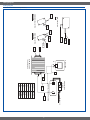
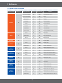
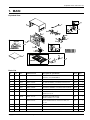
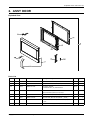
1
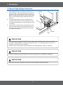
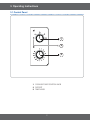
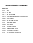
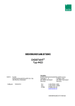
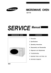
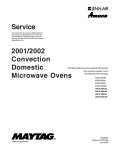
BASIC : CM1079 MODEL : CM1099 MODEL CODE : CM1099/XEU 1. Precaution 6SHFL¿FDWLRQ 3. Disassembly and Reassembly 4. Troubleshooting 5. Wiring Diagrams Refer to the service manual in the GSPN(see rear cover) for the more information. &RQWHQWV 1. Precaution . . . . . . . . . . . . . . . . . . . . . . . . . . . . . . . . . . . . . . . . . . . . . . . . . . . . . . . . . . . . . . . . . . . . . . . . . . . . . .3 1-1 Safety precautions . . . . . . . . . . . . . . . . . . . . . . . . . . . . . . . . . . . . . . . . . . . . . . . . . . . . . . . . . . . . . . . . . . . .4 1-2 Special High Voltage Precautions . . . . . . . . . . . . . . . . . . . . . . . . . . . . . . . . . . . . . . . . . . . . . . . . . . . . . . . . .5 6SHFL¿FDWLRQV . . . . . . . . . . . . . . . . . . . . . . . . . . . . . . . . . . . . . . . . . . . . . . . . . . . . . . . . . . . . . . . . . . . . . . . . . . .6 2-1 Features . . . . . . . . . . . . . . . . . . . . . . . . . . . . . . . . . . . . . . . . . . . . . . . . . . . . . . . . . . . . . . . . . . . . . . . . . . . . .6 7DEOHRI6SHFL¿FDWLRQV . . . . . . . . . . . . . . . . . . . . . . . . . . . . . . . . . . . . . . . . . . . . . . . . . . . . . . . . . . . . . . . . . .6 3. Operating Instructions . . . . . . . . . . . . . . . . . . . . . . . . . . . . . . . . . . . . . . . . . . . . . . . . . . . . . . . . . . . . . . . . . . . .7 3-1 Control Panel . . . . . . . . . . . . . . . . . . . . . . . . . . . . . . . . . . . . . . . . . . . . . . . . . . . . . . . . . . . . . . . . . . . . . . . . .7 3-2 Features & External Views . . . . . . . . . . . . . . . . . . . . . . . . . . . . . . . . . . . . . . . . . . . . . . . . . . . . . . . . . . . . . . .8 4. Disassembly and Reassembly . . . . . . . . . . . . . . . . . . . . . . . . . . . . . . . . . . . . . . . . . . . . . . . . . . . . . . . . . . . . . .9 4-1 Disassembly of Magnetron, Motor Assembly and Lamp . . . . . . . . . . . . . . . . . . . . . . . . . . . . . . . . . . . . . . . .9 4-2 Replacement of High Voltage Transformer . . . . . . . . . . . . . . . . . . . . . . . . . . . . . . . . . . . . . . . . . . . . . . . . . 11 4-3 Replacement of Door Assembly . . . . . . . . . . . . . . . . . . . . . . . . . . . . . . . . . . . . . . . . . . . . . . . . . . . . . . . . . .13 4-4 Replacement of Drive Motor . . . . . . . . . . . . . . . . . . . . . . . . . . . . . . . . . . . . . . . . . . . . . . . . . . . . . . . . . . . .14 4-5 Replacement of Control Circuit Board . . . . . . . . . . . . . . . . . . . . . . . . . . . . . . . . . . . . . . . . . . . . . . . . . . . . .15 5. Troubleshooting . . . . . . . . . . . . . . . . . . . . . . . . . . . . . . . . . . . . . . . . . . . . . . . . . . . . . . . . . . . . . . . . . . . . . . . .16 5-1 Malfunction . . . . . . . . . . . . . . . . . . . . . . . . . . . . . . . . . . . . . . . . . . . . . . . . . . . . . . . . . . . . . . . . . . . . . . . . . .16 5-2 Unsatisfactory Cooking . . . . . . . . . . . . . . . . . . . . . . . . . . . . . . . . . . . . . . . . . . . . . . . . . . . . . . . . . . . . . . . .18 5-3 Part Check List . . . . . . . . . . . . . . . . . . . . . . . . . . . . . . . . . . . . . . . . . . . . . . . . . . . . . . . . . . . . . . . . . . . . . . .18 6. Wiring Diagrams . . . . . . . . . . . . . . . . . . . . . . . . . . . . . . . . . . . . . . . . . . . . . . . . . . . . . . . . . . . . . . . . . . . . . . . .19 6-1 Wiring Diagrams. . . . . . . . . . . . . . . . . . . . . . . . . . . . . . . . . . . . . . . . . . . . . . . . . . . . . . . . . . . . . . . . . . . . . .19 8. Reference . . . . . . . . . . . . . . . . . . . . . . . . . . . . . . . . . . . . . . . . . . . . . . . . . . . . . . . . . . . . . . . . . . . . . . . . . . . . . .21 8-1 Model name standard . . . . . . . . . . . . . . . . . . . . . . . . . . . . . . . . . . . . . . . . . . . . . . . . . . . . . . . . . . . . . . . . .21 8-2 Customer inquiry cases and countermeasures . . . . . . . . . . . . . . . . . . . . . . . . . . . . . . . . . . . . . . . . . . . . . .23 2 1. Precaution 3 1. Precaution Follow these special safety precautions. Although the microwave oven is completely safe during ordinary use, repair work can be extremely hazardous due to possible exposure to microwave radiation, as well as potentially lethal high voltages and currents. 1-1 Safety precautions ( ) 13. Design Alteration Warning: Use exact replacement SDUWVRQO\LHRQO\WKRVHWKDWDUHVSHFL¿HGLQ thedrawings and parts lists of this manual. This is especially important for the Interlock switches, described above. Never alter or add to the mechanical or electrical design of the MWO. Any design changes or additions will void the manufacturer’s warranty. Always unplug the unit’s AC power cord from the AC power source before attempting to remove or reinstall any component or assembly. 14. Never defeat any of the B+ voltage interlocks. Do not apply AC power to the unit (or any of its assemblies) unless all solid-state heat sinks are correctly installed. 15. Some semiconductor (“solid state”) devices are easily damaged by static electricity. Such components are called Electrostatically Sensitive Devices (ESDs). Examples include integrated FLUFXLWVDQG¿HOGHIIHFWWUDQVLVWRUV,PPHGLDWHO\ before handling any semiconductor components or assemblies, drain the electrostatic charge from your body by touching a known earth ground. 16. Always connect a test instrument’s ground lead to the instrument chassis ground before connecting the positive lead; always remove the instrument’s ground lead last. 17. When checking the continuity of the witches or transformer, always make sure that the power is OFF, and one of the lead wires is disconnected. 18. Components that are critical for safety are indicated in the circuit diagram by shading, or . 19. Use replacement components that have the same UDWLQJVHVSHFLDOO\IRUÀDPHUHVLVWDQFHDQGGLHOHFWULF VWUHQJWKVSHFL¿FDWLRQV$UHSODFHPHQWSDUWWKDWGRHV not have the same safety characteristics as the RULJLQDOPLJKWFUHDWHVKRFN¿UHRURWKHUKD]DUGV NOTE : Connect the oven to a 20A. When connecting the oven to a 15A,make sure that circuit breaker can operate. 1. All repairs should be done in accordance with the procedures described in this manual. This product complies with Federal Performance Standard 21 CFR 2. Microwave emission check should be performed to prior to servicing if the oven is operative. 3. If the oven operates with the door open :Instruct the user not to operate the oven and contact the manufacturer and the center for devices and radiological health immediately. 4. Notify the Central Service Center if the microwave leakage exceeds 5 mW/cm2. 5. Check all grounds. 6. Do not power the MWO from a “2-prong” AC cord. Be sure that all of the built-in protective devices are replaced. Restore any missing protective shields. 7. When reinstalling the chassis and its assemblies, be sure to restore all protective devices, including: nonmetallic control knobs and compartment covers. 8. Make sure that there are no cabinet openings through which people --particularly children--might insert objects and contact dangerous voltages. Examples: Lamp hole,ventilation slots. 9. Inform the manufacturer of any oven foundto have emission in excess of 5 mW/cm2 ,Make repairs to bring the unit into compliance at no cost to owner and try to determine cause. Instruct owner not to use oven until it has been brought into compliance. CENTRAL SERVICE CENTER 10. Service technicians should remove their watches while repairing an MWO. 11. To avoid any possible radiation hazard,replace parts in accordance with the wiring diagram. Also, use only the exact replacements for the following parts: Primary and secondary interlock switches, interlock monitor switch. 12. If the fuse is blown by the Interlock Monitor Switch: Replace all of the following at the same time: Primary, door sensing switch and power relay, as well as the Interlock Monitor Switch. The correct adjustment of these switches is described elsewhere in this manual. Make sure that the fuse has the correct rating for the particular model being repaired. 4 1. Precaution 1-2 Special High Voltage Precautions 1. 2. 3. High Voltage Warning Do not attempt to measure any of WKHKLJKYROWDJHVWKLVLQFOXGHVWKH¿ODPHQWYROWDJHRIWKH magnetron. High voltage is present during any cook cycle. Before touching any components or wiring, always unplug the oven and discharge the high voltage capacitor (See Figure 1-1) The high-voltage capacitor remains charged about 30 seconds after disconnection. Short the negative terminal of the high-voltage capacitor to to the oven chassis. (Use a screwdriver.) +LJKYROWDJHLVPDLQWDLQHGZLWKLQVSHFL¿HGOLPLWVE\FORVH tolerance, safety-related components and adjustments. If WKHKLJKYROWDJHH[FHHGVWKHVSHFL¿HGOLPLWVFKHFNHDFK of the special components. H. V. Capacitor H. V. Diode Short PRECAUTION There exists HIGH VOLTAGE ELECTRICITY with high current capabilities in the circuits of the HIGH 92/7$*(75$16)250(5VHFRQGDU\DQG¿ODPHQWWHUPLQDOV,WLVH[WUHPHO\GDQJHURXVWRZRUNRQRU near these circuits with the oven energized. '2127PHDVXUHWKHYROWDJHLQWKHKLJKYROWDJHFLUFXLWLQFOXGLQJ¿ODPHQWYROWDJHRIPDJQHWURQ PRECAUTION Servicemen should remove their watches whenever working close to or replacing the magnetron. PRECAUTION Never touch any circuit wiring with your hand nor with uninsulated tool during operation. 5 6SHFL¿FDWLRQV 2-1 Features Product Features - Light-Duty Professional Microwave Oven. - Sanitary Stainless Steel Cavity. - Easy-to-use Dial Control Type. 7DEOHRI6SHFL¿FDWLRQV Items Model Model Basic Model New MODEL NAME CM1079 CM1099 Power Source 230V~50Hz 230V~50Hz 1,600W 1,600W 230V / 1,050W (IEC-705) 230V / 1,050W (IEC-705) 2,450MHz 2,450MHz OM75S(31) OM75S(31) Cooling fan motor Cooling fan motor Outside 517 x 297 x 412mm 517 x 297 x 412mm Oven cavity 336 x 225 x 349mm 336 x 225 x 349mm 26Liter 26Liter Net 17.5Kg 17.5Kg Gross 19.0Kg 19.0Kg UK UK Power consumption Microwave Output Power Operating Frequency Magnetron Cooling Method Dimensions (W x H x D) Volume Weight Export zone 6 3. Operating Instructions 3-1 Control Panel 1 2 3 1. COOKING POWER CONTROL KNOB 2. DEFROST 3. TIMER KNOB 7 3. Operating Instructions 3-2 Features & External Views HANDLE DOOR DOOR LATCHES VENTILATION HOLES OVEN LAMP CERAMIC PLATE 8 COOKING POWER CONTOL KNOB SAFETY TIMER KNOB INTERLOCK HOLES 4. Disassembly and Reassembly 4-1 Disassembly of Magnetron, Motor Assembly and Lamp Remove the magnetron including the shield case, permanent magnet, choke coils and capacitors (all of which are contained in one assembly) Parts Explaination Photo Magnetron, Motor Assembly and Lamp 9 Explaination 1. Disconnect all lead wires from the magnetron and lamp. 2. Remove a screw securing air cover. 3. Remove the air cover. 4. Disassembly and Reassembly 4-1 Disassembly of Magnetron, Motor Assembly and Lamp Parts Explaination Photo Magnetron, Motor Assembly and Lamp Explaination 4. Remove screws securing the magnetron to the wave guide. 5. Take out the magnetron very carefully. 6. Remove two screws from the back panel. Take out the fan motor. 7. 10 4. Disassembly and Reassembly 4-1 Disassembly of Magnetron, Motor Assembly and Lamp Parts Explaination Photo Magnetron, Motor Assembly and Lamp Explaination 8. Remove the oven lamp from hole of air cover. NOTE1: When removing the magnetron, make sure that its antenna does not hit any adjacent parts, or it may be damaged. NOTE2: When replacing the magnetron, be sure to remount the magnetron gasket in the correct position and make sure the gasket is in good condition. 4-2 Replacement of High Voltage Transformer Parts Explaination Photo Explaination 1. Discharge the high voltage capacitor. 2. Disconnect all the leads. High Voltage Transformer 11 4. Disassembly and Reassembly 4-2 Replacement of High Voltage Transformer Parts Explaination Photo Explaination 3. Remove the mounting bolts. 4. Replace the High Voltage Transformer After replace, reconnect the OHDGVFRUUHFWO\DQG¿UPO\ High Voltage Transformer 5. PRECAUTION Servicemen should remove their watches whenever working close to or replacing the magnetron. PRECAUTION There exists HIGH VOLTAGE ELECTRICITY with high current capabilities in the circuits of the +,*+92/7$*(75$16)250(5VHFRQGDU\DQG¿ODPHQWWHUPLQDOV,WLVH[WUHPHO\GDQJHURXVWRZRUNRQ or near these circuits with the oven energized. '2127PHDVXUHWKHYROWDJHLQWKHKLJKYROWDJHFLUFXLWLQFOXGLQJ¿ODPHQWYROWDJHRIPDJQHWURQ 12 4. Disassembly and Reassembly 4-3 Replacement of Door Assembly Parts Disassembly Photo Explaination Removal of Door “C” ,QVHUWÀDWVFUHZGULYHULQWRWKHJDS between Door “A” and Door “C” to remove Door “C”. Be careful when handling Door “C” because it is fragile.Then remove the door assembly. Removal of Door Assembly Lift up the Door Assembly from Cavity. Removal of Door “E” Following the procedure as shown in the ¿JXUHLQVHUWDQGEHQGDWKLQPHWDOSODWH between Door “E” and Door “A” until you hear the ‘tick’ sound. Insertion depth of the thin metal plate should be 0.5mm or less. Removal of Key Door & Spring Remove pin hinge from Door “E” Detach spring from Door “E” and key door. 13 4. Disassembly and Reassembly 4-4 Replacement of Drive Motor Parts Explaination Photo Explaination 1. 2. Take out the glass tray, guide roller from oven cavity, disconnect power. Remove turn table motor cover from case bottom. CAUTION : Remove sharp edge after cover removal. Drive Motor 3. 4. Disconnect leads from motor. Remove the screws securing motor to bottom of over cavity. 6. 5. Lift out the motor. When replacing the motor, be sure to remount it in the correct position. NOTE : The shaft of motor should ¿WWLSFRXSOHU Drive Motor 6. COVER FIXING SCREW : MATCHINE SCREW(6006-001170) 14 When reassemble a drive motor cover. give a turn in a DQG¿[ZLWKDVFUHZ NOTE : Bring the spare screw from service center. 4. Disassembly and Reassembly 4-5 Replacement of Control Circuit Board Parts Explaination Photo Explaination 1. Removal of Control Box Assembly SCREW 2. 3. 4. CONTROL BOX 15 Disconnect the connectors from the control box assembly. Remove screws securing the control box assembly Remove the knobs of the control box A’ssy Remove the screw securing the timer. 5. Troubleshooting 5-1 Malfunction 5-1-1 If oven malfunction *Inspection method Oven does not operate. NO Is Fuse OK? Is Primary interlock switch normal? NO YES YES Is the magnetron temperature switch normal? NO Is Power Relay normal? NO Replace switch NO Power supply circuit check point YES Is SMPS power supply cirduit normal? NO Do check power supply circuit NO NO Do check Relay control circuit NO YES Is the IC01 output of PCB normal? Relay control circuit check point Is high voltage dioed normal? YES Checking high voltagecircuts Is high voltage dioed normal? NO YES Is high voltage capacitor normal? NO YES Is magnetron normal? 16 NO 5. Troubleshooting 5-1-2 If food is not heated even though an oven works Food is not heated even though an oven works. Is the latch switch operating normally? NO *Inspection method Method to control latch switch YES Checking high voltage circuits 17 5. Troubleshooting 5-2 Unsatisfactory Cooking Parts Food is not heated. Cause Diagnosis Remedy 1) Open cathode of magnetron Check the terminals with a multimeter to see if the heater circuit is open. Replace magnetron. 2) Defective H. V. Diode Check the H. V. Diode for continuity in the reverse and normal directions using meter. If there is continuity in the reverse direction, the H. V. Diode may be faulty. (In this event H. V. Capacitor will be hot) Replace H. V. Diode. 3) Shorted magnetron Connect megger leads to quick-connect terminal & body of the magnetron if there is continuity, the magnetron may be fuse will be blown) faulty. (In this case the main fuse will be blown) Replace magnetron. 4) Defective magnetron If there is a crack in the magnetron antenna (dome), the magnetron is defective. Replace magnetron. 5) Poor contact of primary interlock switch Check if the screws are secured well to the door hinge. and pressing it ON and OFF repeatedly. Replace or adjust. 6) Open coil of H. V. Transformer Check the continuity of primary coil and secondary coil. If there is no continuity, H. V. Transformer is defective. Replace the H. V. Transformer. 7) Shorted H. V. capacitor Check the continuity of capacitor. If the capacitor shorts, the fuse blows Replace the H. V. Capacitor. 8) Monitor Fuse out &KHFNWKHPRQLWRUIXVHRQWKHQRLVH¿OWHU Replace the Monitor fuse 5-3 Part Check List Symptom Microwave cooking does not work. Fan motor does not rotate. Related Parts Check Points H.V.Transformer 1) Check if the primary and secondary coil is open or shorted. 5HVLVWDQFHRISULPDU\FRLO$SSUR[ 5HVLVWDQFHRIVHFRQGDU\FRLO$SSUR[ 2) Check if the MGT Heater Voltage is approx. 3.3V AC. Caution : High voltage ! Replace. H.V.Capacitor Check continuity of capacitor between two terminals with H.V.wire lead removed. The resistance should be approx. 10MW, it’s failure.. Replace. H.V.Diode 1) If there is no continuity in forward, direction the H.V.Diode is open. 2) If there is continuity in reverse direction, it’s shorted. Replace. Fan motor Check if the motor coil is open. Replace. 18 Remedy 6. Wiring Diagrams 6-1 Wiring Diagrams (This Document can not be used without Samsung’s authorization) 10W15 0.90A 19 6. Wiring Diagrams 6-1 Wiring Diagrams (This Document can not be used without Samsung’s authorization) PRIMARY SWITCH 723 BLU WHT DOOR SENSING SWITCH %27720 YEL WHT ORG BLK BRN WHT BRN MONITOR SWITCH &(17(5 WHT BLU F MAGNETRON FA HIGH VOLTAGE TRANSFORMER R RED HIGH VOLTAGE DIODE TO CHASSIS HIGH VOLTAGE CAPACITOR COLOR RED SYMBOL ORANGE WHITE BLACK BLUE RED YELLOW BROWN RED ORG WHT BLK BLU RED YEL BRN 20 7. Reference 7-1 Model name standard %DRDG&ODVVL¿FDWLRQ USA CMO USA RV Distinguisher 0LGGOH&ODVV¿FDWLRQ Distinguisher Product Code Full Name CMO (Counter-top MWO) W MW USA CMO(EPOXY CAVITY) UTC (Under The Cabinet) U MU USA UTC Browner, Grill G MG USA GRILL Convection C MC USA CONVECTION Sensor S MS USA CMO SENSOR DC MWO D MD USA DC MWO Hospital MWO H MH USA Hospital MWO Ceramic Enamel E ME USA CMO(CERAMIC ENAMEL) SOLO M RM USA RV SOLO CONVECTION C RC USA RV CONVECTION BUILT-IN B RB USA RV BUILT-IN - - SJ USA Junior MWO SOLO H SMH USA OTR SOLO CONVECTION V SMV USA OTR CONVECTION SOLO 1 M1 EUROPE SOLO(EPOXY CAVITY) GRILL 2 M2 EUROPE GRILL(EPOXY CAVITY) SOLO 1 CE1 EUROPE SOLO(CERAMIC ENAMEL) GRILL 2 CE2 EUROPE GRILL(CERAMIC ENAMEL) M R USA Junior SJ USA OTR SM EUROPE Epoxy Cavity M EUROPE Ceramic Enamel CE EUROPE Quartz GRILL G2 - - G2 EUROPE Quartz GRILL EUROPE Power Grill PG - - PG POWER GRILL CK - - CK EUROPE CONVECTION C - - C EUROPE CONVECTION SOLO W FW EUROPE SOLO FULLY BUILT-IN GRILL G FG EUROPE GRILL FULLY BUILT-IN CONVECTION C FC EUROPE CONVECTION FULLY BUILT-IN EUROPE Convection EUROPE Fully Built-In F 21 Exploded Views and Parts List 1. MAIN Exploded View Parts List No. Lvl. Loc. Material Code Description & Specification SNA 1 2 T002 DE97-00191A ASSY-TRAY CERAMIC; CM1049,-,T3.2,COMMERCI SA 1 2 2 P001 DE97-00190A ASSY STIRRER; CM1049,ALS SA 1 2-1 3 T036 DE31-00009A BLADE-STIRRER; CM1030M,ALP1050,T0.8 SNA 1 2-2 3 T074 DE60-80043A SPACER-STIRRER; TEFLON,W6.3,T2 SNA 4 2-3 3 T037 DE61-00098A HOLDER-STIRRER; CM1030M,TEFLON,WHT SNA 1 2-4 3 M078 DE69-90054A CLIP-STIRRER; 5mm,TEFLON-PFA,CM1819/29 SA 4 3 2 M051 DE71-00163A COVER-CEILING; CM1049,MICA SHEET,T0.5,W12 SA 1 4 2 M049 DE31-10173C MOTOR SYNCHRONOUS; SEMI-COMM,21V,16.7/20R SA 1 5 1 DE96-00964C ASSY POWER PACK; CM1079-A/XEU,0.8 CU.FT SA 1 5-1 2 M038 DE26-00051B TRANS H.V; SHV-E1049B,230V,50Hz,2360V/3.4 SA 1 6 2 M155 DE96-00240G ASSY BASE PLATE; SEMI COMM 1059/1069,-,-, SA 1 6-1 3 M045 DE96-00042A ASSY BASE PLATE SUB; -,-,-,3RD-1.0,SEPARA SA 1 Copyright© 1995-2012 SAMSUNG. All rights reserved. Qty. 1 Exploded Views and Parts List No. Lvl. Loc. Material Code Description & Specification SNA 6-1-1 4 M048 DE80-10001G BASE-PLATE; 3RD,GI-SGCC,T0.6,W345,L565 SNA 1 6-1-2 4 M047 DE61-40066A FOOT; PP,BLK SA 2 6-2 3 M042 DE91-70061H ASSY H.V.FUSE; -,THV060T-0900-H,5KV0.90A, SA 1 6-3 3 M527 DE59-00002A DIODE-H.V; MWO ALL,2CL4512H,-,450mA 13KV, SNA 1 6-4 3 M039 2501-001285 C-OIL; 1.13uF,2100V(CLASS P),AL CAN TYPE, SA 1 6-5 3 M040 DE61-00419A BRACKET-HVC; CM1049,EGI-SECC,T0.8 SNA 1 7 2 M011 DE61-50541A BRACKET-EARTH; GI-SGCC,T1.0,W15,L8 SNA 1 8 1 B022 DE94-01862D ASSY BODY LATCH; MC455TCRCSR/XE,CONTRABAS SNA 1 8-1 2 DE72-00137G LATCH-BODY; AMC6158/JMC9158,PBT SA 1 8-2 2 B048 3405-001034 SWITCH-MICRO; 125/250VAC,16A,200gf,SPST-N SA 2 8-3 2 B046 3405-001032 SWITCH-MICRO; 125/250VAC,16A,200GF,SPDT SA 1 8-4 2 B010 DE66-00093A LEVER-SWITCH(A); NC2000,PP,NTR,HANDLE SA 1 8-5 2 B011 DE66-00094A LEVER-SWITCH(B); NC2000,PP,NTR,HANDLE SA 1 9 1 W002 DE96-00743A ASSY WIRE HARNESS-A; CM1059,-,TCM SNA 1 10 2 M457 DE47-20173A THERMOSTAT; NT-101,125/250V,905,605,1 SA 1 11 2 M035 OM75P(31)ESGN ASSY-MGT; ASSY-MGT 12 2 M037 DE71-60016E COVER-AIR; CM1049,PP,FH44N,SEMI-COM SA 1 13 2 M036 4713-001524 LAMP-INCANDESCENT; 230V,20W SA 1 14 2 M020 DE96-00108C ASSY MOTOR FAN; CM1059/XEU,230V50HZ,2500R SA 1 14-1 3 P109 DE71-00061A COVER-MOTOR; 2 & 2 PROJECT,PP,TB53,2 & 2 PROJ SA 1 14-2 3 H096 DE31-90051A BLADE-FAN; -,PP,-,D130,-,T,- SA 1 14-3 3 M023 DE31-10177C MOTOR FAN; SMF-1049EA,-,-,230V50Hz,15mm,- SNA 1 15 2 M017 DE96-00010C ASSY NOISE FILTER; -,SN-3WED(12),250V12A, SA 1 15-1 3 M019 3601-001019 FUSE-CARTRIDGE; 250V,12A,SLOW-BLOW,CERAMI SA 1 16 1 M001 DE64-01740A PANEL-OUTER; CM1059/1069,STAINLESS-STS430 SA 1 17 1 M015 DE96-00180C ASSY POWER CORD; BSI,Flag,250V/13A,H07RN- SA 1 18 2 M052 DE73-90027A FERRITE-CORE; T13.8,NI-ZN,BNF-14(K150),L2 SA 1 19 2 DE69-00909A PAD SHEET; ALL MODEL CMO,HDPE,T0.03,W400, SA 1 2 Qty. 1 Copyright© 1995-2012 SAMSUNG. All rights reserved. Exploded Views and Parts List 2. ASSY DOOR Exploded View Parts List No. Lvl. Loc. Material Code Description & Specification SNA 1 1 D049 DE94-03005A ASSY DOOR; CM1089,STSS,MANDOLIN SA 1 1-1 2 D037 DE94-03002A ASSY DOOR A; CM1089,STSS,MANDOLIN SA 1 1-2-1 3 D019 DE64-02745A HANDLE-DOOR; COMMERCIAL,AL,MANDOLIN SNA 1 1-3 2 D010 DE61-80003A HINGE-LOWER; ME6144W/XSA,SSEC,T2.3,W26,L7 SA 1 1-4 2 D009 DE61-80002A HINGE-UPPER; WHT,SSEC,T2.3,W26,L77,ZPC3 SA 1 1-5 2 D011 DE64-00264A KEY-DOOR; 3RD-W NEW,POM,-,-,BLK,-,- SA 1 1-6 2 D007 DE61-00199A SPRING-KEY; M1977,HSWR-SWRH,D6,25 1/4,25 SC 1 1-7 2 D004 DE92-50127H ASSY DOOR E; -,-,BLACK,COATING,T0.8 SC 1 Copyright© 1995-2012 SAMSUNG. All rights reserved. Qty. 3 Exploded Views and Parts List No. Lvl. Loc. Material Code Description & Specification SNA 1-8 2 D006 DE64-40012D DOOR-C; JES1036NL02,ROH,EMBO HEIGHT 0.8mm SA 1 1-9 2 D005 DE01-00002B FILM-DOOR; CM1089,PET,T0.15,W290,L169,NTR SA 1 4 Qty. Copyright© 1995-2012 SAMSUNG. All rights reserved. Exploded Views and Parts List 3. ASSY CONTROL BOX Exploded View Parts List No. Lvl. Loc. Material Code Description & Specification SNA 1 1 C082 DE94-03007A ASSY CONTROL BOX; CM1099,230V 50HZ,STSS S SNA 1 1-1 2 F002 DE96-00738A ASSY-TIMER CONTROL; MW71E,DAM-TCM1-00,-,W SA 1 1-3 2 C001 DE94-03006A ASSY CONTROL PANEL; CM1099,STSS ST-430 T0 SA 1 1-4 2 C029 DE64-02753A KNOB-DIAL; COMMERCIAL,PC,HB,BLACK,MANDOLI SNA 2 Copyright© 1995-2012 SAMSUNG. All rights reserved. Qty. 5 7. Reference 7-1 Model name standard (Continued) (Blue Color) : Not Used Baoad &ODVVL¿FDWLRQ CHINA KOREA Distinguisher C D EUROPE USA - A Distinguisher Cavity / type Distinguisher SOLO / CMO M Inverter SOLO I CERAMIC ENAMEL E CERAMIC ENAMEL(Clay) C Epoxy W 0LGGOH&ODVV¿FDWLRQ Grill / Browner G Quartz Grill / Browner Q Conv. C TBMO / Power Grill T Commercial O STSS S CERAMIC ENAMEL E CERAMIC ENAMEL(Clay) C Epoxy W SOLO / CMO M Inverter SOLO I Grill / Browner G Quartz Grill / Browner Q Conv. C TBMO / Power Grill T Commercial O STSS S CERAMIC ENAMEL E CERAMIC ENAMEL(Clay) C Epoxy W SOLO / CMO M Inverter SOLO I Grill / Browner G Quartz Grill / Browner Q Conv. C TBMO / Power Grill T Commercial O STSS S CERAMIC ENAMEL E CERAMIC ENAMEL(Clay) C SOLO / CMO M Inverter SOLO I Grill / Browner G Quartz Grill / Browner Q Conv. C TBMO / Power Grill T Commercial O Epoxy W STSS S Full Name CME / CMC / CMW / CMS CIE / CIC / CIW / CIS CGE / CGC / CGW / CGS CQE / CQC / CQW / CQS CCE / CCC / CCW / CCS CTE / CTC / CTW / CTS COE / COC / COW / COS DME / DMC / DMW / DMS DIE / DIC / DIW / DIS DGE / DGC / DGW / DGS DQE / DQC / DQW / DQS DCE / DCC / DCW / DCS DTE / DTC / DTW / DTS DOE / DOC / DOW / DOS ME / MC / MW / MS IE / IC / IW / IS GE / GC / GW / GS QE / QC / QW / QS CE / (CC) / (CW) / CST TE / (TC) / TM / TST OE / OC / OW / OS AME / (AMC) / AMW / AMS AIE / AIC / AIW / AIS AGE / (AGC) / AGW / AGS AQE / AQC / AQW / AQS ACE / ACC / ACW / ACS ATE / ATC / ATW / ATS AOE / AOC / AOW / AOS CHINA C SOLO(MW ONLY) W CFW / CFG / CFC / CFI / CFT KOREA D GRILL G DFW / DFG / DFC / DFI / DFT EUROPE - CONVECTION C DFW / DFG / DFC / DFI / DFT USA A INVERTER I FW / FG / FC / FI / FPG TBMO / Power Grill T AFW / AFG / AFC / AFI / AFT Fully Built-In F USA OTR SM SOLO(MW ONLY) H SMH / SMB / SMV / SMI / STB EUROPE OTR EM GRILL G EMH / EMG / EMV / EMI / EMT CHINA OTR UM CONVECTION V UMH / UMG / UMV / UMI / UMT KOREA OTR PM INVERTER I TBMO / Power Grill T CST : EUROPE STSS Conv. FPG : EUROPE FBI POWER GRILL TST : EUROPE TBMO with STSS cavity SMB : USA Grill OTR TM : EUROPE TBMO with epoxy cavity STB : USA TBMO OTR 22 PMH / PMG / PMV / PMI / PMT 7. Reference 7-2 Customer inquiry cases and countermeasures Symptom Cause The oven works automatically whenever the power is turned on. Heating Ground The oven sometimes beeps. Strange popping sounds are produced ZKLOH¿VKLVFRRNHG Countermeasures It may happen due to power failure or abnormal voltage. It may happen when the door does not close completely. In many cases, it may happen when the power level is incorrectly set. It may happen when the door does not close completely. It may happen when the oven is out of order. Ground problem may happen when the oven is placed in a humid area and the over is not grounded. Ground is not provided by an extended electric outlet. The oven beeps every minute unless the food is in the oven after the food is cooked completely. The oven occasionally beeps during cooking. 6LQFH¿VKLVVDOW\DQG maintains its moisture, it is cooked while making a series of soft popping sounds. (The liquid may come out of WKH¿VKZKHQWKH¿VKLV cooked.) 23 Connect the power plug three seconds after disconnecting the power plug. Close the door completely => Press the Cancel button => Press the Start button. Select HIGH/MEDIUM/LOW by pressing the Power Level button. - MEDIUM/LOW: This function is used to cook the food slowly. Close the door completely. => Press the Cancel button. => Press The Start button. Contact the nearest Samsung after-sales service center. If the oven is placed in a humid area, buy an electric wire in a store selling electrical products. (Electric wires for home use are also allowed) Ground the oven through the electric wire. Buy an electric wire in a store selling electrical products. (Electric wires for home use are also allowed) Ground the oven through the electric wire. Open and close the door again. (Beeping sounds indicate that the food is ready to be removed from the oven after cooking is complete.) )RRGZLWKERQHVVXFKDV¿VKHJPDFNHUHODQGSRUN (e.g. pork chops) is cooked while making a series of soft popping sounds. Wrap the food completely so that food particles or spattered oils do not stick to the oven ZDOOVRUÀRRU 7. Reference 7-2 Customer inquiry cases and countermeasures (Continued) Symptom Cause It may happen when food particles stuck to RYHQZDOOVRUÀRRU Clean the inside of the oven. => Remove strange smell through the Deodorant button => If the strange smell still remains, place a piece of lemon on the turntable and operate the oven for 5 minutes by pressing the Deodorant button.(However, the smells produced from the food exposed such as herbal remedies are not removed.) (UURUVDUHFODVVL¿HG with Failure and Nonfailure. Refer to the section of ERROR in User Manual. Visit the nearest Samsung Service Center or local dealer to buy accessories. Before visiting, check the model name printed on the lower right side of the front panel of the oven. Since the government recommends the reduction of electricity, the power saving function is performed for number display like that power cord is unplugged when the oven is not used. (Numbers are displayed when another button is pressed or when the door opens.) Strange smell is produced in the oven. Error Countermeasures Accessory Number does not appear on the display screen. It happens when the power saving function is activated. 24 GSPN (GLOBAL SERVICE PARTNER NETWORK) Area Web Site Europe, CIS, Mideast & Africa gspn1.samsungcsportal.com Asia gspn2.samsungcsportal.com North & Latin America gspn3.samsungcsportal.com China china.samsungportal.com © Samsung Electronics Co., Ltd. March 2013 Printed in Korea