1
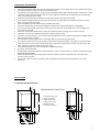
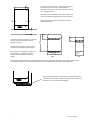
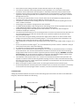
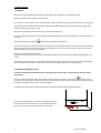
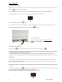
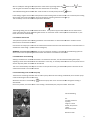
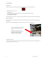
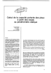
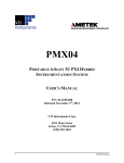
DIGITAL MODULATING BOILERS
FOR HEATING AND SANITARY HOT WATER
CMX15
CMX18
CM15
CM18
INSTALLATION INSTRUCTIONS AND USER GUIDE
Please read these instructions before installing or using this appliance for the first time.
INDEX
1 IMPORTANT INFORMATION………………………………………………………….. 3
2 INSTALLATION……………………………………………………………………………..
3
2.1 LOCATION AND INSTALLATION……………………………………….. 3
2.2 FILLING LOOP………………………………………………………………..
5
3 COMMISIONING………………………………………………………………………….
6
3.1 HEATING……………………………………………………………………..
6
3.2 SANITARY HOT WATER………………………………………………..
6
4 LIMITATION OF THE MAXIMUM OUTPUT…………………………………..
7
5 DESCRIPTION OF THE CONTROL PANEL………………………………………
9
6 USING THE BOILER……………………………………………………………………...
10
6.1 TURNING ON AND OFF……………..………………………………..
10
6.2 BLOCKING THE CONTROLS…………………………………………..
10
6.3 HEATING……………………………………………………………………..
10
6.3.1 Ambient thermostat….……………………………….
11
6.3.2 Modulation of the heating…………………………
11
6.3.3 Anti-blocking of the accelerator pump………
11
6.3.4 Heater safety……….……………………………………
12
6.4 SANITARY HOT WATER (S.H.W.)……………………………………. 13
6.4.1 Adjusting the S.H.W. temperature.…………..
13
6.4.2 S.H.W. safety…..……………………………………….
13
7 MAINTENANCE………………………………………………………………………….
14
8 TROUBLESHOOTING………………………………………………………………….
14
9 TECHNICAL DATA………………………………………………………………………
15
10 ENVIRONMENTAL INFORMATION..…………………………………………
16
11 MAIN COMPONENTS…….………………………………………………………..
16
12 WIRING…….…………………………………………………………………………….
17
2
Gabarrón CM&CMX
1 IMPORTANT INFORMATION
The boiler’s guarantee does not cover any damaged caused by the non-observance of any of these instructions.
This manual must be conserved and given to any new user.
This appliance is not destined for use by anyone (including children) with reduced physical, sensorial or mental
capacities or those who do not know how to use the appliance, unless they are supervised or instructed by a
person responsible for their safety.
Complete all the plumbing work before connecting the boiler to the electricity supply.
Check that the voltage on the indicator plate of the boiler coincides with the voltage of the mains circuit to
which it is going to be connected.
Any re-installation must be performed by qualified electricians.
The use of these boilers in the presence of gases, explosives or inflammable objects is prohibited.
The air inputs and outputs of the boiler ensure its correct operation and protect it from over-heating. They
must never be covered.
This boiler must be disconnected from the mains electricity before carrying out any internal repairs.
The boiler must not be installed directly below a power take-off point.
The boiler must be installed in such a manner that the switches or other controls cannot be touched by anyone
who is using the bath or shower.
The installation must be performed in accordance with current electricity regulations.
This appliance is destined to be permanently connected to a fixed installation. The power circuit of the boiler
must incorporate an omni-polar cut-off switch with a separation between the contacts of at least 3 mm. No
other appliances should be powered from this supply
The electricity supply circuit must incorporate a differential switch.
This boiler must be earthed.
All the models incorporate different safety elements. If one or more of them are activated, consult the section
PROBLEMS & SOLUTIONS.
Do not use the fitted pressure relief valve to flush the system as particles trapped in the valve will cause
incorrect valve operation.
In time, the presence in the air of smoke, dust and pollution may stain the walls and areas close to the
appliance.
2 INSTALLATION
2.1 LOCATION AND INSTALLATION
450
265
DIMENSIONS & CONNECTION
3
830
8
A cold water input 1/2"
B safety valve drain
C S.H.W. outlet 1/2"
D heating return 3/4"
E heating out 3/4"
F electrical connection
760
30
30
3
F
A BC
D
E B F
D E
80
80
160
200
200
300
350
245
285
355
435
535
3
The boiler must be located in a place free from frost
and moisture. This boiler is not designed to be
installed in the open air. The boiler must be installed
in an upright position.
The boiler must be located above 200 mm above any
object to allow the heating elements to be replaced.
Please maintain the shown clearances around the
CMX and CM boiler.
10
200
10
The boiler must be installed in a solid wall
able of resist the weight of the boiler
when full of water.
Mark the holes positions using the wall
bracket as a template as per this figure.
Drill the holes and plug with appropriate
plugs. If there is any doubt as to the
strength of the wall please consult an
expert.
CMX
CM
Fit the bracket (CMX models have two brackets) to the wall by using high strength screws. Hang the boiler from
the brackets to secure it to the wall. Now the boiler may be plumbed into the central heating system.
If the boiler is fitted with a thermostatic mixing blending valve
remove the two metallic transport protections at the bottom of
the boiler. They are part of the packaging.
4
Gabarrón CM&CMX
•
•
•
•
•
•
•
•
•
•
•
•
•
•
•
•
•
Ensure that the mains voltage available coincides with that shown on the rating label.
The electrical installation must comply with the current regulations. The cross-section of the power
conductors must be sufficient for the rated power or the power to which the boiler has been limited.
Install the necessary electrical protections as indicated in the current regulations. In the event of these
regulations not being complied with, the manufacturer will not be liable for any bodily injury or material
damage that may occur.
It is necessary to install the boiler in such a manner that it can be separated from all the poles of the
electricity mains with a contact clearance width of a minimum of 3 mm.
The hydraulic connections to the heating and S.H.W. circuit must be carried out respecting the out and
return marked on the boiler.
Install purges in the radiators and high points of the installation.
In models CM18 and CM15, install a filling valve for the heating circuit as close as possible to the boiler. In
models CMX18 and CMX15, the filling valve is incorporated inside the boiler.
Install the discharge valve at the lowest point of the installation, in order to be able to empty the
installation completely if necessary.
The system should be flushed prior to connecting the boiler to remove all particles from the pipe work. Do
not use the fitted pressure relief valve to flush the circuit as particles trapped in the valve will cause
incorrect valve operation.
We recommend running the heating circuit pressure safety valve to the drain in order to avoid a water
2
spillage in the event of the pressure exceeding 3 kg/cm . It should be left open to the atmosphere; any
connection to the outlet pipe must be of a minimum diameter of 15 mm.
2
CMX models only: It is essential to run the safety pressure valve of the S.H.W. header rated at 7 kg/cm to a
drain.
2
If the circuit pressure exceeds 5 kg/cm , it is recommended that a pressure reducer is installed in the pipe
at the exit from the water meter of the dwelling.
It is essential to connect the boiler to a good earth connection.
The boiler can be controlled by an external regulator, for example an ambient thermostat or an ambient
chrono-thermostat. This must be connected to the terminals on the electronic board once the existing
bridge between both terminals has been suppressed. (See the electrical diagram). WARNING : Use a volt
free connection. The use of an external regulator is essential for the modulating system to work. Please
check compatibility with thermostat manufacturer’s installation instructions.
The installation must be performed in such a manner as to facilitate maintenance and repair work. The
hydraulic connections must be made using flexible couplings or hoses in order to facilitate disconnecting
the boiler from the circuit. If these aspects of the installation are not adhered to, the Technical Service will
not be obliged to repair the boiler.
Before carrying out any work inside the boiler, do not forget to disconnect the electrical supply.
If the heating installation includes hydraulic thermostatic valves or automatic area controls, it is necessary
to avoid at all times interrupting the water circulation, as this will activate the safety thermostat.
2.2 FILLING LOOP
A filling loop should be fitted at some point to allow the heating system to be filled. This boiler is not fitted with a
filling loop. Remove the flexible hose after filling.
Double check valve
Heating return
Mains water supply
Flexible Hose
5
3 COMMISSIONING
3.1 HEATING
Check that the drainage points located in the lower part of the installation are completely closed.
Open the purges of the installation and the boiler.
Use a good corrosion inhibitor in the heating system. Use the inhibitor according to the manufacturer’s instructions.
The heating system should be filled using the approved installed filling loop until the water pressure gauge reads
between approximately 1 and 1.5 bar.
Disconnect the heating system from the approved installed filling loop.
Close the installation purges when water begins to flow through them. The boiler automatic air eliminator must not
be closed.
Start the heating by pushing the
button the heating display will light up.
Select a set point higher than the temperature indicated on the heating display and check the consumption once the
operating indicator of the central heating resistances lights up. The S.H.W. has priority; if the S.H.W. is connected
and consuming, this point cannot be verified.
Purge the installation again if necessary.
Reinstate any possible losses in pressure by opening the filling valve until the pressure gauge reads between 1 and
1.5 bar.
If the boiler includes the option of radiant floor heating (requested on placing the order), the central heating safety
thermostat will activate at 80°C and the temperature of the heating resistance cannot exceed 50°C.
3.2 SANITARY HOT WATER (S.H.W.)
Proceed to fill the 50-litre accumulator tank, opening the tap of the S.H.W. to draw out the air from the water
accumulator.
Once the water is flowing normally, shut off the tap and connect the S.H.W. by pushing the
button. Select a
resistance temperature for the S.H.W. higher than the temperature shown on the S.H.W, display and check that the
consumption indicator of the S.H.W. resistances lights up.
Check that once the set point temperature has been reached, the consumption indicator goes off.
If the boiler is fitted with a thermostatic mixing blending valve
the temperature of the hot water is user adjustable by turning
the control knob on the valve at the bottom of the boiler.
6
Gabarrón CM&CMX
4 LIMITATION OF THE MAXIMUM OUTPUT
It is possible to limit the maximum output of the boilers by selecting the combination required in the table
corresponding to each model.
The boiler output will never exceed the selected value.
The boiler will continue to modulate in heating mode on all the lower steps, adapting to the installation’s
consumption.
It is necessary to employ an external ambient thermostat or a chrono thermostat.
The output in S.H.W. on the CMX15 and CMX18 models is also limited to the maximum value of the corresponding
table.
To access the electronic card, disconnect the boiler from the mains and remove the front panel.
Removing the upper screws, tilt the control panel. Locate the main card.
Location of electronic card.
ATTENTION!
The switches are upside down.
Move the switches with a small screwdriver and make them coincide with the corresponding combination on the
tables for each boiler model.
Replace the front panel following the steps in reverse and connect the boiler to the mains.
IMPORTANT: Check immediately before activating the modulation system with a clamp meter that the consumption
corresponds to the output selected.
On the CMX models, turn off the S.H.W. pressing the
button to verify the heating consumption.
7
LIMITATION OF OUTPUT ON MODELS CM18 & CMX18
MAXIMUM OUTPUT
LIMITED TO :
MAX.
CURRENT
PHASE
MAX.
CURRENT
R:
PHASE
S:
MAX.
CURRENT
PHASE
POSITION OF
THE SWITCHES
T:
MAXIMUM OUTPUT
LIMITED TO :
MAX.
CURRENT
18kW
78.3A
15kW
65.2A
12kW
52.2A
9kW
39.1A
6kW
26.1A
3kW
13.0A
1 2 3 4
1 2 3 4
18kW
26.0A
26.0A
26.0A
15kW
13.0A
26.0A
26.0A
12kW
13.0A
13.0A
26.0A
9kW
13.0A
13.0A
13.0A
6kW
-
13.0A
13.0A
3kW
-
-
13.0A
ON
1 2 3 4
ON
ON
1 2 3 4
1 2 3 4
ON
ON
1 2 3 4
1 2 3 4
ON
ON
1 2 3 4
1 2 3 4
ON
ON
1 2 3 4
1 2 3 4
ON
POSITION OF
THE SWITCHES
Connection 230V~
ON
1 2 3 4
ON
Connection 3x400V~+N
LIMITATION OF OUTPUT ON MODELS CM15 & CMX15
MAXIMUM OUTPUT
LIMITED TO :
MAX.
CURRENT
PHASE
MAX.
CURRENT
R:
PHASE
S:
MAX.
CURRENT
PHASE
T:
1 2 3 4
21.7A
21.7A
21.7A
13kW
13.0A
21.7A
21.7A
12kW
21.7A
21.7A
8.7A
11kW
13.0A
13.0A
21.7A
10kW
21.7A
8.7A
13.0A
9kW
13.0A
13.0A
13.0A
8kW
13.0A
8.7A
13.0A
7kW
8.7A
13.0A
8.7A
6kW
8.7A
8.7A
8.7A
5kW
-
13.0A
8.7A
4kW
8.7A
8.7A
-
3kW
-
-
13.0A
2kW
8.7A
-
-
MAX.
CURRENT
15kW
65.2A
13kW
56.5A
12kW
52.2A
11kW
47.8A
10kW
43.5A
9kW
39.1A
8kW
34.8A
7kW
30.4A
6kW
26.1A
5kW
21.7A
4kW
17.4A
3kW
13.0A
2kW
8.7A
1 2 3 4
ON
1 2 3 4
1 2 3 4
ON
ON
1 2 3 4
1 2 3 4
ON
1 2 3 4
ON
1 2 3 4
ON
ON
1 2 3 4
1 2 3 4
ON
ON
1 2 3 4
1 2 3 4
ON
ON
1 2 3 4
1 2 3 4
ON
ON
1 2 3 4
1 2 3 4
ON
ON
1 2 3 4
1 2 3 4
ON
ON
1 2 3 4
1 2 3 4
ON
ON
1 2 3 4
1 2 3 4
ON
ON
ON
1 2 3 4
1 2 3 4
ON
1 2 3 4
ON
ON
It is possible to check the actual configuration of a boiler by pressing the
The heating display will show
Connection 230V~
button for three seconds.
followed by the value of the return probe of the heating circuit.
On pushing
button the display will show
according to the preceding tables.
8
MAXIMUM OUTPUT
LIMITED TO :
1 2 3 4
15kW
Connection 3x400V~+N
On pushing
POSITION OF
THE SWITCHES S
ON
POSITION OF
THE SWITCHES
button again the display will show
followed by the value of the limited maximum output
followed by the actual modulated output value.
Gabarrón CM&CMX
5 DESCRIPTION OF THE CONTROL PANEL
MODELS CMX18 & CMX15
Increase
S.H.W.
temperature
Increase
heating water
temperature
Heating temp.
and other
messages
S.H.W.
temperature and
other messages
Blockage
indicator
S.H.W. On / Off
button
On / Off button
Reduce S.H.W.
temperature
Block / Unblock
S.H.W. resistances
operating
indicator
Heating
resistances
operating
indicator
Reduce
heating water
temperature
Heating On / Off
button
MODELS CM18 & CM15
Increase
heating
Heating temp.
and other
messages
Blockage
indicator
On / Off button
Block / Unblock
Heating
resistances
operating
indicator
Reduce heating
Heating On / Off
button
9
6 USING THE BOILER
6.1 TURNING ON AND OFF
When the boiler is connected to the mains it will perform a general self-check and, if any defect is detected, it will be
indicated on the heating or S.H.W. displays.
Push the
button to start the boiler up. The same button will turn the boiler off when pushed again.
If the heating display only shows a small red dot, the heating function is switched off.
To start the heating, push the
button.
The same occurs with the Sanitary Hot Water (S.H.W.): if the display is off apart from a small red dot, the S.H.W
function is switched off; to switch the S.H.W. on, press the
button.
Only CMX models:
There is an independent switch at the back of the
boiler. It will connect ON and OFF the boiler.
6.2 BLOCKING THE CONTROLS
By keeping the
button pressed down for a few seconds, the padlock will light up
.
The control buttons of the boiler will be blocked and no button will respond when pressed. Internally all the settings
remain the same and the boiler functions normally.
To unblock the buttons, press the button down for a few seconds until the padlock light goes off. If the boiler is
disconnected from the mains or there is a failure in the house’s electricity supply, the buttons will also be unblocked.
6.3 HEATING
Always maintain an adequate pressure in the heating circuit. The water pressure gauge should mark about 1.5 bar.
If the pressure rises above this, open the draining valve of the heating circuit located in the house slightly until the
pressure reaches 1.5 bar when cold.
If the pressure is lower, open the filling valve of the heating circuit located under the boiler until the proper pressure
is reached.
To start the heating, push the
button. At the end of the heating time, we can turn this function off by pressing
the same button (the display will then only show a small red dot).
When the heating is on, the display will show the temperature of the water.
10
Gabarrón CM&CMX
We can modify the setting of the temperature of the water by pushing either the
and using the same buttons to adjust the value that flashes on the display.
The modified setting will be stored after a few seconds or instantly if we push the
button or the
button
button.
If the setting is higher than the actual temperature of the heating water and the S.H.W is not connected, the heating
will connect and a small red indicator of the consumption of heating resistances will light up.
This will always occur if the ambient temperature demands it.
The heating setting can be varied between 8 and 85°C. The symbol H appears after the 85 value or before the 8
value. If we select this value, the heating will function in anti-freeze
anti freeze mode: if the temperature falls below 7°C, the
boiler will connect automatically.
6.3.1 Ambient thermostat
The optimum operation of the heating installation is achieved when an ambient thermostat or ambient chrono
thermostat is connected to the boiler.
Connect the normally open contact
contact of the ambient thermostat to the terminals of the electronic card of the boiler in
substitution of the bridge. (See the electrical diagram).
WARNING : Use a volt free connection. The use of an external regulator is essential for the modulating system
syst
to
work. Please check compatibility with thermostat manufacturer’s installation instructions.
6.3.2 Modulation of the heating
Always provided that an ambient thermostat is connected to the boiler, this will work modulating the output,
adjusting it to the heat necessities of the installation. In this way, on cold days the boiler will use more power and on
warmer days the power consumed will be reduced.
This occurs automatically and requires no action on the part of the user; just follow the specific instructions
in
of the
ambient thermostat or chrono thermostat.
6.3.3 Anti-blocking
blocking of the accelerator pump
The boiler has a blocking control on the circulation pump. Whenever the heating is turned off, the circulation pump
continues working for two minutes more.
m
Whenever the boiler is started using
button the pump will run for 10 seconds even though the heating is
switched off.
Once every month, even if the boiler or the heating is switched off, the pump will run for 10 seconds.
If, despite everything,, the pump seizes, follow the following
followin
steps in order to unblock it:
-
-
First disconnect the boiler from the mains.
mains
Take off the front panel after removing the two screws on
the upper part of the boiler to access the pump.
Remove the front cover as shown in the figure. A small
quantity of water may appear at this moment, stop it from
splashing by using a cloth or absorbent paper.
Using a suitable screwdriver, turn the shaft several times
until it moves smoothly.
Replace the cover and the front panel with the screws.
11
6.3.4 Heater safety
FLOW FAILURE
If the error E3 appears on the display, the boiler has detected a flow failure in the heating circuit.
The possible causes of this error are:
-
A blocked pump.
All the thermostat valves are closed and there is no circuit that permits the water return.
The circuit pressure is insufficient.
The heating circuit is blocked.
After solving the cause of the error, the boiler must be turned off and re-started to eliminate the display message.
BOILER OVERHEATING
If the boiler detects an overheating in the heating circuit the safety thermal limiter will operate. The boiler will be
switched off.
Once the cause of the overheating has been eliminated, the thermal limiter must be re-armed.
To do so, unscrew the black cap and push
the small pin behind it until you hear a
click.
The limiter will not re-arm until the
temperature in the heating header goes
below 100°C or 80°C if the boiler is
adapted for radiant floor heating.
HEATING SAFETY VALVE
2
A safety valve set at 3 kg/cm will activate if the pressure of the heating circuit passes said value, expelling water. It
is essential that this valve runs to a drain.
12
Gabarrón CM&CMX
6.4
.4 SANITARY HOT WATER (S.H.W.)
The CMX15 and CMX18 boilers have a mixed function of modulated heating and the preparation
prepa
of sanitary hot
water. The S.H.W. function has priority over the heating and so the outputs are never added together.
A 50-litre
litre header tank lagged with CFC free insulation accumulates the sanitary hot water.
6.4.1 Adjusting the S.H.W. temperature
To switch on the S.H.W. push the
button. This function can be switched off by pushing the same button (the
display will only show a small red dot).
When the S.H.W. is switched on, the display will show the actual temperature in the S.H.W. accumulation
accumula
tank.
The setting of the S.H.W. temperature can be modified by pushing both the
button or the
button and
adjusting the setting that flashes on the display. The modfied setting will be stored automatically afer a few seconds,
or instantly if we push the
button.
The S.H.W. setting can be varied between 20 and 55°C.
6.4.2 Sanitary Hot Water safety
OVERHEATING OF THE S.H.W.
If the boiler detects an overheating in the sanitary hot water tank the safety thermal limiter will operate. The boiler
willl be switched off, including the heating.
Once the cause of the overheating has been eliminated, the thermal limiter of the S.H.W. must be re-armed.
re
To do so, unscrew the black cap and push the small pin behind it until you hear a click.
The limiter will not re-arm
arm until the temperature in the S.H.W. header tank has gone down to below 80°C.
S.H.W. SAFETY VALVE
2
A safety valve set at 7 kg/cm will activate if the pressure in the S.H.W. accumulator tank exceeds said value,
expelling water. It is essential that this valve runs to a drain.
S.H.W. RETENTION VALVE
This prevents the S.H.W. accumulator tank from emptying even when the water supply to the dwelling is cut off.
13
7 MAINTENANCE
Gabarrón electric boilers do not need any special maintenance, only the following should be checked:
-Check the pressure indicated by the pressure gauge frequently, ensuring that it is between 1 and 1.5 bar when cold.
- Never start the boiler when it is empty.
- Never start the boiler when the S.H.W. tank is empty; to fill it for the first time open a hot water tap and wait until
water comes out of it.
-Precaution against freezing. In dwellings that are frequently unoccupied or at risk of freezing, an anti-freeze of the
appropriate quality can be added to the water of the heating installation – the concentration must not exceed 30%
in volume.
- Clean the surfaces of the boiler with a damp cloth, having previously disconnected it from the mains. Do not use
solvents or abrasive products.
8 TROUBLESHOOTING
Problem
Possible cause
No current entering boiler.
Boiler will not start
Overheating of the heating.
Overheating of S.H.W.
S.H.W. tank empty.
Error E1
Error E2
Error E3
Lack of heating water flow.
Error E4
Error E5
Error E6
Heating safety valve expels water
S.H.W. safety valve expels water.
The buttons do not respond
Low temperature in the installation.
14
Heating water out temperature
probe defective.
Heating water return temperature
probe defective.
Pump blocked.
Valves shut.
Air in the installation.
Pump blocked.
Valves shut.
Air in the installation.
Configuration error of the maximum
limited output.
S.H.W. temperature probe
defective.
Excessive pressure in cold.
Expansion vessel breakdown.
Water entering heating circuit.
Entering water pressure too high.
S.H.W. expansion vessel breakdown
Control panel blocked
Heating setting low.
Setting of ambient thermostat low.
Resistances broken down.
Badly calculated installation.
Solution
- Check the installation.
- Turn independent switch On. Only
CMX models. See Section 6.1.
See Section 6.3.4.
See Section 6.4.2.
Open a hot water tap until the water
flows.
Contact Technical Service
Contact Technical Service
Unblock – see instructions
Open valves.
Purge the installation
Unblock – see Section 6.3.3.
Open valves.
Purge the installation.
See Section 5 LIMITATION OF
OUTPUT
Contact Technical Service
Adjust to between 1 & 1.5bar.
Change.
Check filling valve.
Install a pressure reducer.
Change.
See Section 10.2 BLOCKING THE
CONTROLS
Regulate.
Regulate.
Contact Technical Service.
Increase output.
Gabarrón CM&CMX
9 TECHNICAL DATA
Frequency
Connection 3x400V+N~
Output limited to 18kW; Maximum intensity
Output limited to 15kW; Maximum intensity
Output limited to 13kW; Maximum intensity
Output limited to 12kW; Maximum intensity
Output limited to 11kW; Maximum intensity
Output limited to 10kW; Maximum intensity
Output limited to 9kW; Maximum intensity
Output limited to 8kW; Maximum intensity
Output limited to 7kW; Maximum intensity
Output limited to 6kW; Maximum intensity
Output limited to 5kW; Maximum intensity
Output limited to 4kW; Maximum intensity
Output limited to 3kW; Maximum intensity
Connection 230V~ single phase
Nominal maximum intensity 18kW
Nominal maximum intensity 15kW
Maximum converted intensity at 13kW
Maximum converted intensity at 12kW
Maximum converted intensity at 11kW
Maximum converted intensity at 10kW
Maximum converted intensity at 9kW
Maximum converted intensity at 8kW
Maximum converted intensity at 7kW
Maximum converted intensity at 6kW
Maximum converted intensity at 5kW
Maximum converted intensity at 4kW
Maximum converted intensity at 3kW
S.H.W. available time with 15kW
S.H.W. available time with 13kW
S.H.W. available time with 12kW
S.H.W. available time with 11kW
S.H.W. available time with 10kW
S.H.W. available time with 9kW
S.H.W. available time with 8kW
S.H.W. available time with 7kW
S.H.W. available time with 6kW
S.H.W. available time with 5kW
S.H.W. available time with 4kW
S.H.W. available time with 3kW
S.H.W. available time with 2kW
Weight
Insulated steel heater header
50 litre stainless steel insulated S.H.W. accumulator
Stainless steel plated resistance elements INCOLOY800
Stainless steel plated resistance elements INCOLOY800
6 litre expansion vessel
S.H.W. 2 litre expansion vessel
Electronic regulation of heater modulation
Electronic regulation S.H.W..
Digital display
0-4 kg/cm2 pressure gauge
Accelerator pump
Automatic purge
TRIACS silent power switches
Heating flow detector
100°C heating temperature limiter
80°C S.H.W. temperature limiter
3kg/cm2 heating safety valve
7kg/cm2 S.H.W. safety valve
S.H.W. retention valve
Heating circuit entry valve
Ambient thermostat intake
Anti-electrolysis S.H.W. hoses.
included
1
CMX15
Hz
A
A
A
A
A
A
A
A
A
A
A
A
A
A
A
A
A
A
A
A
A
A
A
A
A
A
min
min
min
min
min
min
min
min
min
min
min
min
min
kg
No CFC
S.H.W.
Heating
50
21.7
21.7
21.7
21.7
21.7
13.0
13.0
13.0
8.7
13.0
8.7
13.0
1
65.2
56.5
52.2
47.8
43.5
39.1
34.8
30.4
26.1
21.7
17.4
13.0
5’49”
6’42”
7’16”
7’56”
8’43”
9’41”
10’54”
12’27”
14’32”
17’26”
21’48”
29’04”
43’36”
70
CMX18
50
26.0
26.0
26.0
13.0
13.0
13.0
1
78.3
65.2
52.2
39.1
26.1
13.0
5’49”
7’16”
9’41”
14’32”
29’04”
70
CM15
50
21.7
21.7
21.7
21.7
21.7
13.0
13.0
13.0
8.7
13.0
8.7
13.0
1
65.2
56.5
52.2
47.8
43.5
39.1
34.8
30.4
26.1
21.7
17.4
13.0
32
-
CM18
50
26.0
26.0
26.0
13.0
13.0
13.0
1
78.3
65.2
52.2
39.1
26.1
13.0
32
-
using connecting bridge included
15
UPS 25-40
P
(kPa) H(m)
40
4
3
20
2
1
0
0
0
0
0
0.5
1.0
20
1.5
0.5
2.0
2.5
3.0
3.5
1
40
60
4.0
4.5
3
Q(m /h)
(l/min)
Working curves of the accelerator pump.
10 ENVIRONMENTAL INFORMATION
Gabarrón boilers are manufactured within a certified environmental management system. From the design stage, all
the production phases are performed taking into account the most rigorous environmental requirements. For
example, the selection of materials involves guaranteeing their biodegradability, re-use and recycling.
When this boiler’s long, useful life is over; it must be handed in to an electrical equipment collection point for proper
recycling. By ensuring that this product is correctly disposed of, you will help to avoid any possible negative effects
on the environment and public health that could occur if this product is not properly handled. To obtain more
detailed information on the recycling of this product, contact your local authority, your waste disposal service or the
shop where you purchased the product.
These regulations only apply in EU member countries.
11 MAIN COMPONENTS
-
16
Heating expansion vessel 6L
S.H.W. expansion vessel 2L
S.H.W. expansion vessel hose CMX
50 L S.H.W. insulated tank
Insulated heating header tank
Thermostatic blending valve
Circulation pump 25-40 (130)
Circulation pump 25-60 (130)
Main electronic card with support
S.H.W. electronic card with support
Controls card CM15 & CM18
Controls card CMX15 & CMX18
Temperature probe, white connector
Temperature probe, black connector
15 kW heating resistance, inc. joint 140
18 kW heating resistance, inc. joint 140
15 kW S.H.W. resistance & S.H.W. joint
S.H.W. resistance joint
¾” heating flow detector
0-4 bar pressure gauge
100°C thermal limiter
80°C thermal limiter
Automatic purge
2
3kg/cm heating valve
2
7kg/cm S.H.W. valve
S.H.W. retention valve
½” shut off valve
Adhesive polyester controls cover 220x60
Adhesive polyester controls cover 140x50
ref. 60091510
ref. 60091515
ref. 60100020
ref. 60100072
ref. 60101700
ref. 60101880
ref. 60190070
ref. 60190071
ref. 60101310
ref. 60101320
ref. 60100510
ref. 60100540
ref. 60100580
ref. 60100590
ref. 60100750
ref. 60100760
ref. 60100700
ref. 60100068
ref. 60100800
ref. 60100820
ref. 60091140
ref. 60091150
ref. 60091280
ref. 60100840
ref. 60100850
ref. 60100830
ref. 60091160
ref. 60100502
ref. 60100508
Gabarrón CM&CMX
12 WIRING
17
18
Gabarrón CM&CMX
NOTES
19
www.elnur.es
Manufactured by:
ELNUR s.a.
Pol. Ind. “El Nogal” Villa Esther, 11
28110, ALGETE - Madrid
Customer Service Department:
+44 (0)1942 670119 (UK)
As a part of the policy of continuous product improvement, Elnur s.a reserves the right to alter
specifications without notice.
20
@2011
Cod. 60100005 rev.0
Gabarrón CM&CMX