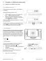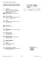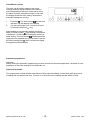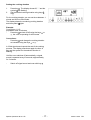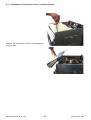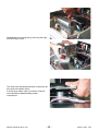
1
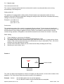
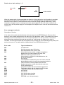
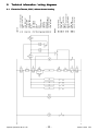
SERVICE MANUAL COOKERS Euro Steam Cooker © Electrolux Muggenhofer Straße 135 D-90429 Nürnberg Germany Fax +49 (0)911 323 1022 Spares Operation Edition: 08.01 Publ.-Nr.: 599 51 19 69 685 EN Contents 1. 1.1 General features .................................................................................................... 3 Models .................................................................................................................... 3 2. 2.1 Appliance data........................................................................................................ 4 Dimensions and capacities .................................................................................... 4 3. Control elements .................................................................................................... 5 4. 4.1 4.2 4.3 4.4 4.5 Component data .................................................................................................... 6 The electronic oven control (WOEC control unit) ............................................... 6 Power supply / relay board ..................................................................................... 8 The steam thermostat / relay steam ...................................................................... 9 Actuators .............................................................................................................. 10 The temperature sensor PT 500 / buzzer / devaporization opening / safety thermostat ................................................................................................. 11 Steam generator / - cover / fan cover .................................................................. 12 4.6 5. 5.1 Operation of setting and control units .................................................................. 13 Operation of the WOEC oven control .................................................................. 13 13 5.1.1 Setting the time of day ......................................................................................... 13 13 13 5.2 Setting the oven functions .................................................................................... 14 5.3 Heatable drawer ................................................................................................... 24 6. 6.1 6.2 6.3 Technical equipment / general information .......................................................... 25 Fan after-running / appliance cooling ................................................................... 25 Setting time 4 seconds ........................................................................................ 25 Safety switch-off of the oven ................................................................................ 25 7. 7.1 7.2 7.3 Fault diagnosis / What to do when ...? ................................................................. 26 Problems when baking ........................................................................................ 26 Measures in case of malfunctions ....................................................................... 26 Service test .......................................................................................................... 27 8. 8.1 8. 8.1 8.2 8.3 8.4 8.5 Technical information / wiring diagrams .............................................................. 32 Electrolux Therma, 230 V, without drawer heating ............................................... 32 Technical information / wiring diagrams .............................................................. 32 Electrolux Therma, 230 V, without drawer heating ............................................... 32 Electrolux Therma, 230 V, with drawer heating .................................................... 33 Husqvarna, 230 V, with oven lights which can be switched off separately........... 34 Electrolux Therma, 400 V, with drawer heating .................................................... 35 Description of function ......................................................................................... 36 9. 9.1 9.2 9.3 9.4 9.5 9.6 9.7 9.8 Service information .............................................................................................. 37 Removing the two-part casing cover ................................................................... 37 Disassembly of switch panel ............................................................................... 37 Disassembly of WOEC control unit ..................................................................... 39 Disassembly of power supply .............................................................................. 40 Disassembly of steam generator ......................................................................... 41 Disassembly of temperature sensor / steam thermostat .................................... 47 Further information ............................................................................................... 49 ESD electrostatic discharge and its effect on the control ................................. 49 Spares Operation 08.01 A. B. -2- 599 51 19 69 EN 1. 1.1 General features Models Marke Electrolux Electrolux Electrolux Electrolux Electrolux Electrolux Electrolux Electrolux Electrolux Electrolux Electrolux Electrolux Electrolux Electrolux Electrolux Electrolux Electrolux Modell EOB998w EOB998k EOB998x EBSL7TC.3 EBSL7TC.3 EBSL7TC.3 EBKSL7TC.3 EBKSL7TC.3 EBKSL7TC.3 EBSL70TC.3 EBSL70TC.3 EBSL70TC.3 EBKSL7GTC.3 EBKSL7GTC.3AL EBSL7GTC.3 EBSL70GTC.3 EBSL70GTC.3AL PNC 941 047 059 941 047 060 941 047 061 944 211 967 944 211 968 944 211 969 944 211 970 944 211 971 944 211 972 944 211 973 944 211 974 944 211 975 944 270 000 944 270 001 944 270 002 944 270 004 944 270 005 Husqvarna Husqvarna Husqvarna QCE541W QCE541K QCE541X 941 047 056 941 047 057 941 047 058 Therma Therma Therma Therma Therma Therma Therma Therma Therma BOKD.2ST BOKD.2ST BOKD.2ST BOD/60.2ST BOD/60.2ST BOD/60.2ST BOD.2ST BOD.2ST BOD.2ST 944 211 796 944 211 797 944 211 798 944 211 799 944 211 800 944 211 801 944 211 879 944 211 880 944 211 881 Spares Operation 08.01 A. B. -3- 599 51 19 69 EN 2. 2.1 Appliance data Dimensions and capacities Built-in ovens 55 cm Outside dimensions Height Width Depth Depth with open door Total weight, net 59.5 cm 54.8 cm 56.7 cm 100.2 cm 45.0 kg Oven inside dimensions Height Width Depth Capacity 31.5 cm 40.8 cm 40.6 cm 52.0 l Built-in ovens 60 cm Outside dimensions Height Width Depth Depth with open door Total weight, net 59.4 cm 59.2 cm 56.7 cm 100.9 cm 47.0 kg Oven inside dimensions Height Width Depth Capacity 31.5 cm 40.8 cm 40.6 cm 52.0 l Power absorption Upper heat Lower heat Backplate heating element (hot air) Pizza level Steam generator Small area grill Large area grill Turbo grill Drawer heating (appliances with heated drawer) Spares Operation 08.01 A. B. 1,000 W 1,000 W 2,400 W 3,400 W 1,800 W 1,900 W 2,900 W 1,900 W 500 W -4- 599 51 19 69 EN 3. Control elements Built-in ovens control panel with electronic timer oven door handle oven door with front pane of solid glass drawer (only in appliances with heatable drawer) Control panel Touching keys for functions 1 2 3 4 5 6 7 8 ON OFF child lock meat probe heating oven functions +/- setting for temperature and time cooking duration switch-off time 9 10 11 12 13 14 15 drawer heating timer / minute minder time of day pilot lamp drawer (only in appliances with heatable drawer) water drawer hot plate controller, front right water drawer The touching keys for functions are designed as push buttons with rubber caps in all appliances of the brand Therma. With all other appliances from the list of models (chapter 1.1), these keys are designed as touch-sensor keys. Spares Operation 08.01 A. B. -5- 599 51 19 69 EN 4. Component data 4.1 The electronic oven control (WOEC control unit) The WOEC central unit consists mainly of display, buzzer, temperature limiter /thermostat ? and microprocessor. This control, which o o o regulates the set temperature via the oven sensor, possibly switches off the food thermometer, is set by the two bit generators and the short-stroke keys, selects the relay board. buzzer microprocessor display Temperature limiter (colour red) temp. temp. temp. Spares Operation 08.01 A. B. -6- >= 105 °C oven switches off >= 85 °C cooling fan switches on <= 80 °C cooling fan switches off 599 51 19 69 EN The electronic oven control The display area Symbols service child lock oven functions oven temperature heating phase meat probe cannot be used meat probe cooking duration cooking end timer/minute minder Spares Operation 08.01 A. B. -7- 599 51 19 69 EN 4.2 Power supply / relay board This board consists of a number of relays, a transformer (1) and other components, which are necessary for the power supply of the relays and the control board. The safety relay (2) is a power relay with 20 A contacts and serves the protection of the power circuit. This board receives the electrical control impulses transferred by the control board, and, according to the impulses received, the concerned heating element resp. ventilator is powered. The secondary relay circulating air is a service resp. secondary relay with a lower amperage (3 A at the contacts), which selects the circulation fan (3). The control relays (4) (max. 16 A at the contacts) select the different heating elements resp. the fan; their number changes depending on the type of appliance. 1 2 3 4 transformer for low voltage power supply main switch-off relay (safety relay) secondary relay, circulation fan supply relay for heating element and hot-air fan (control relay) Spares Operation 08.01 A. B. -8- 599 51 19 69 EN 4.3 The steam thermostat / relay steam The cooking temperature with steam cooking is between 96 °C and 97 °C. The temperature fluctuations are lower than 1 °C. It is measured by the steam thermostat and maintained automatically by the electronic, in which the steam generator (chapter 4.6) is switched on resp. off. steam thermostat relay steam switching on resp. off of actuators (see principle diagram chapter 8.1 and actuators chapter 4.4) position of the temperature sensor Spares Operation 08.01 A. B. -9- 599 51 19 69 EN 4.4 Actuators Depending on the set function, the actuators open or close the devaporization valve and the water vapor valve (see table below). total view They are selected by both relays steam. devaporization valve water vapor valve devaporization valve water vapor valve steam cooking closed closed Edevaporization open open conventional closed open The stroke is approx. 6 mm. The zero position of the ram ( 0V ) is the extended state. Spares Operation 08.01 A. B. - 10 - 599 51 19 69 EN 4.5 The temperature sensor PT 500 / buzzer / devaporization opening / safety thermostat safety thermostat temperature sensor PT 500 buzzer acoustic indication lack of water in the steam generator (chapter 4.6) devaporization opening + devaporization hose Sound level: 75 dB( A ) Fig.: Electrical resistance of the sensor depending on the ambient temperature Spares Operation 08.01 A. B. - 11 - 599 51 19 69 EN 4.6 Steam generator / - cover / fan cover The fan cover Material: chromed brass The steam generator cover Material: chrome steel The cover prevents the steam generator from soiling. The steam generator Material: stainless steel Capacity: 0.7 l Electric power: 1,800W Seat for 2 thermo sensors (Klixons) TR1/ F2: 120 °C signal sound lack of water TR2/ F2: 200 °C steam generator switches off 200 °C Klixon The 200 °C Klixon can be recognized by the unilaterally bent-up tag. Spares Operation 08.01 A. B. - 12 - 599 51 19 69 EN 5. Operation of setting and control units 5.1 Operation of the WOEC oven control 5.1.1 Setting the time of day After connecting the power supply, 12:00 flashes in the display. Wait until the display indicates 12:05. 1. 2. Press key for a short time. The digits 12 00 light, : is flashing between the digits. Set the current time of day within 4 seconds using the key or . Otherwise, please press the key anew for a short time. After 4 seconds the flashing signal goes out. Thus the time of day is fixed. In order to correct the time (e.g. summer/winter time), press key and change the settings by key or . In this case the signal sound is without meaning. 5.1.2 First cleaning Remove all objects out of the oven as well as possibly existing stickers and protective foils at the appliance. Do not remove the nameplate! To remove possible traces from production, clean the oven before the first use. Wash and dry oven, control panel and oven door with a cloth that is moistened with some washing-up water. In doing so, the oven lighting can be switched on. Press key . 5.1.3 First heating The oven must be heated once before the first use. Please take care of a good room ventilation. 1. Switch on the oven with key . 2. Select the function hot air with key by tapping it repeatedly. 3. Set 230 °C with key . Operate the closed oven at this temperature for approximately 60 minutes. 4. Switch off the oven with key . Spares Operation 08.01 A. B. - 13 - 599 51 19 69 EN 5.2 Setting the oven functions By tapping the key repeatedly it is possible to select the oven functions. The order of functions corresponds to the representation listed below. Lighting Separate setting e.g. for cleaning or preparation of cooking processes and switched on with all functions Steam cooking Steam generator, fixed setting 96 °C. . Interval cooking Hot air 75% and steam generator 25% in change, pre-setting 180 °C Hot air Backplate heating element and oven fan pre-setting 170 °C Pizza level pre-setting 230 °C Turbo grill Small area grill with oven fan pre-setting 180 °C Small area grill Grill heating element pre-setting 230 °C Large area grill Upper heat and grill heating element pre-setting 230 °C Upper / Lower heat pre-setting 200 °C Drying Lower heat with oven fan pre-setting 40 °C Low temperature cooking Backplate heating element with oven fan fixed setting 120/80 °C Spares Operation 08.01 A. B. - 14 - 599 51 19 69 EN Switching on/off the oven 1. Switch on the oven with key . Before setting function, temperature and time, you must always press key . Except: timer A short 3-fold signal sound indicates an error in setting. In this case press key and start anew with key . Oven function and temperature are switched on with the electronic control and switched off manually at the desired time with key or automatically according to the time programme. 2. Switch off the oven with key . Setting the oven function The functions steam cooking, interval cooking, hot air, pizza level, grill levels and upper/lower heat can be used alternatively for different dishes. - Select the intended function by tapping key repeatedly. The symbol for the set function is indicated in the display. A practice-oriented temperature is assigned to every function. If you do not change the temperature, the function switches on after 4 seconds. Oven temperature By setting a function, the display indicates the temperature pre-setting. - Set a temperature between 40 and 230 °C with the or key. The selected temperature keeps to be indicated in the display. With the functions hot air, pizza level and upper/lower heat, the symbol heating phase lights. When the temperature has been reached, a signal sound can be heard and the symbol heating phase goes out. Spares Operation 08.01 A. B. - 15 - 599 51 19 69 EN Timer/Minute minder The timer can be used to observe and check cooking durations and procedures in the kitchen, even independent of the oven. It also can be set at the same time with automatic timings. In this case the display shows the timer setting, whereas the automatic settings are running. 1. 2. Press key . The timer symbol and the time indication :00 are flashing in the display. You can set timings from 1 minute to 9 hours 59 minutes using keys or . Approximately 4 seconds after setting, the timing starts, the timer symbol lights and the current time is indicated. A 3-fold signal sounds points to the rundown setting. The timer symbol is flashing and the signal sound is repeated every 15 seconds. It can be set off by pressing key . After 2 minutes the signal sound goes out automatically. Automatic programmes Important! Before setting the automatic programmes you have to select function and temperature, otherwise it is not possible to do any time settings for the automatic run. Switch-off automatic The programmes cooking duration and switch-off time start immediately (current time) with the process of setting and end with the set time. The oven is on from the time of setting until the switch-off time. Spares Operation 08.01 A. B. - 16 - 599 51 19 69 EN Setting the cooking duration 1. 2. Press key . The display shows 00, : and the symbol are flashing. Set the desired cooking duration using keys or . For the cooking duration you can set times between 1 minute and 9 hours 59 minutes. The display shows the remaining cooking duration and the symbol lights. Example: Current time 11.15, preparation time 45 minutes. Press key and set 00.45 using the keys , the oven is operating for 45 minutes. or Corrections: Press key and change the cooking duration as intended using the keys or . A 3-fold signal sound reports the end of the cooking process. The display now shows again the time of day and the symbol for the selected function is flashing. Until the oven switches off automatically, a signal sound is repeated every15 seconds, approximately for 2 minutes. - Switch off signal sound and oven with key . Spares Operation 08.01 A. B. - 17 - 599 51 19 69 EN Setting the switch-off time 1. 2. Press key . The display shows the current time of day, : and the symbol are flashing. Set the desired switch-off time using the keys or -. The switch-off time cannot be set beyond 24 hours. The display shows the switch-off time and the symbol lights. Example: Current time 11:15, the dish should be ready by 12.00. Press key and set 12.00 using the keys , the oven is in operation until 12.00. or Corrections: Press key and change the switch-off time as intended using the keys or . A 3-fold signal sound reports the end of the cooking process. The display now shows again the time of day and the symbol for the selected function is flashing. Until the oven switches off automatically, a signal sound is repeated every 15 seconds, approximately for 2 minutes. - Switch off signal sound and oven with key . Spares Operation 08.01 A. B. - 18 - 599 51 19 69 EN Switch-on and off automatic Programming, which switches on the oven automatically at a later time and switches the oven off again automatically after the cooking duration has run down. 1. 2. 3. 4. Press key . The display shows 00, : and the symbol are flashing. Set the desired cooking duration using the keys or Now press key . Set the desired switch-off time using the keys or . Example: Current time 7.30. Preparation time 45 minutes, the dish should be ready by 12.00. - Set 00.45 using key and 12.00 using key and keys and or or . , The oven switches on automatically at 11.15 (12.00 minus 00.45) and off again automatically at 12.00. - The display shows the switch-off time, : and the symbol are flashing. After 4 seconds oven function and lighting are switched off, the display shows the symbol of the selected function without frame, the current time of day and the symbols and . When the oven switches on automatically with the desired function, the symbol in the display goes out and the remaining cooking duration is indicated. Check: By pressing key you can check the set cooking duration and with key the switch-off time in the display. Correction: Press key or key and change the cooking duration or switch-off time as intended using the keys or . A 3-fold signal sound reports the end of the cooking process. The display now shows again the time of day and the symbol for the selected function is flashing. Until the oven switches off automatically, a signal sound is repeated every 15 seconds, approximately for 2 minutes. Switch off signal sound and oven with key . Spares Operation 08.01 A. B. - 19 - 599 51 19 69 EN Steam-cooking programmes Important! The steam-cooking programmes must be set by the automatic programme cooking duration or switch-off time. Due to the automatic approx. 5-minute devaporization at the end of the cooking duration and due to the heating time of approx. 2 minutes, settings below 10 minutes have little effect. During the devaporization the door can steam up easily. During steam operation use only the grates. When opening the door, steam is still escaping from the hot dishes. The slight steam on the control panel will disappear after a short time. To prevent the accumulation of lime, you can use decalcified water, e.g. from a commercial water filter appliance. Important! Use only water. When the water has been used up, a buzzer will sound. Shortly after refilling water, the buzzer goes out again. Steam cooking 1. Fill in water (approx.0.7 litres) into the water drawer in the control panel, not directly into the steam generator. The water is sufficient for approx. 30 minutes. 2. Switch on the oven with key . 3. Select the function steam cooking with key . 4. Press key or key and set the desired cooking duration resp. switch-off time using the keys or . After approximately 2 minutes the first steam can be seen. A simple signal sound indicates when the cooking temperature of approx. 96 °C have been reached. A 3-fold signal sound reports the end of the cooking duration. 5. Switch off signal sound and oven with key . - After the oven has cooled down, absorb the remaining water with a sponge and afterwards possibly re-wipe it with some drops of vinegar. That the oven can dry completely, leave the oven door open approx. 2 cm (jam a wooden scoop in). Spares Operation 08.01 A. B. - 20 - 599 51 19 69 EN Interval cooking The permanent change from 75% hot air to 25% steam goes automatically. 1. 2. 3. 4. Fill approx.0.7 litres water into the water drawer in the control panel. The water storage is sufficient for approx. 1 hour. Switch on the oven with key . Select the function interval cooking with key and set the intended temperature using the keys or . Press key or key and set the desired cooking duration resp. switch-off time using keys or . Proceed as with steam cooking. Spares Operation 08.01 A. B. - 21 - 599 51 19 69 EN Meat probe Cooking with the core temperature automatic The meat probe is to measure the temperature in the core of the dish during cooking. When the set temperature has been reached, the oven will switch off automatically. 1. 2. Put the tip of the meat probe in the centre of the thickest part of the cooking food and put baking sheet, frying dishes or grill grate into the oven, Put the connector of the meat probe up to the handle into the plug-in jack in the right sidewall of the oven and close the oven. The display shows the symbol 3. 4. . After you have set function and oven temperature, press key . The time display in the display changes to centrigrade and the temperature to 70° C. Set the desired core temperature to between 30 and 99° C using the keys or . Recommended core temperatures for: Roast beef Roast beef or fillet of beef Rare Medium Roast Pork Roast lamb Roast veal very rare 80° C 45° C 50° C 60° C 80 85° C 70 75° C 75° C The display shows the symbol of function, the set oven temperature (red), the symbol meat probe and the core temperature of the cooking food. The increase of the core temperature is indicated in the display. Check or correction By pressing key it is possible to inquire the set core temperature and, if necessary, to correct it using the keys or . A 3-fold signal sound reports that the pre-set core temperature has been reached. Until all functions switch off automatically, a signal sound is repeated every 15 seconds, for approximately 2 minutes. - Switch off signal sound and oven with key . Spares Operation 08.01 A. B. - 22 - 599 51 19 69 EN Child lock The oven control can be protected against unintended switching on or adjusting by a safety lock. When the child lock activated, playing children cannot do any settings with the appliance, which may lead to endangering. Use this feature even with longer absence. The child lock can only be activated when the oven is switched off. Activation of child lock When the child lock is activated you have to press the key child lock simultaneously with the setting processes. This is also valid for corrections. 1. Press and keep pressed key , then press key and keep both keys pressed for approximately 4 seconds, until the display shows the symbol . The display shows the symbol child lock is activated. 2. to show that the Switch off the appliance with key . Deactivation of child lock - Press keys and simultaneously until the symbol in the display goes out. Service symbol In case of malfunctions with the electronic control, the display indicates the service symbol and an error code instead of the temperature indication. - - Switch off the fuse. Switch the fuse on again after some minutes and try to switch on the oven. When the service symbol lights again, an error code is indicated. The cooling of the appliance is running continuously for safety reasons. If necessary, switch off the appliance again by the fuse. Spares Operation 08.01 A. B. - 23 - 599 51 19 69 EN 5.3 Heatable drawer You can preheat dishes in it. 1. 2. Switch on the appliance with key and the drawer heating with key . Pilot lamp 12 is on. The temperature is regulating automatically. At the same time you can use an automatic programme; oven function and drawer heating are switched together. 3. Switch off the drawer heating with key , or the drawer heating and appliance with key . Spares Operation 08.01 A. B. - 24 - 599 51 19 69 EN 6. Technical equipment / general information 6.1 Fan after-running / appliance cooling When the appliance has switched off, the housing fan continues operating, until the temperature has sunk below 200° C. In case of less than 200° C, the housing fan is running approx. 10 minutes. The remaining heat is indicated until the temperature has fallen to 40° C. 6.2 Setting time 4 seconds After switching on and after all settings, the next setting step has to start within 4 seconds. The signal sound confirms the expiry of 4 seconds. By pressing the corresponding key you can produce the readiness for setting right away. 6.3 Safety switch-off of the oven When setting function and temperature without a time limit, the safety switch-off switches off the oven automatically, depending on the set temperature. - with temperature setting to 120° C after 12 hours with temperature setting to 230° C after 6 hours. Spares Operation 08.01 A. B. - 25 - 599 51 19 69 EN 7. Fault diagnosis / What to do when ...? 7.1 Problems when baking 3UREOHP Baking or frying good is not swelling up properly 3RVVLEOHFDXVH wrong temperature setting 0HDVXUH Check the set temperature in accordance with the information from the table baking or frying good does temperature too low Increase temperature setting. not get brown Check the cooking condition, possibly reduce time. wrong material of baking tins Use only dark baking tins with upper/lower heat. baking or frying good gets too temperature too high Check the set temperature in dark accordance with the information from the table; if necessary, reduce temperature and increase time. baking good gets too dry baking duration too long Check the set temperature in because of a too low accordance with the temperature information from the table; if necessary increase temperature and reduce time. baking good is too damp due to a too high temperature Set the lower temperature enough moisture could not be value of the table. baked thoroughly Too much liquid in the dough. Prepare dough with less liquid. 7.2 Measures in case of malfunctions 3UREOHP The oven does not function. The oven does not get warm despite switched-on function and temperature. Oven lighting does not function. Meat probe does not function. Service symbol lights. The time of day is flashing in the electronic timer. Spares Operation 08.01 A. B. 3RVVLEOHFDXVH malfunction in power supply automatic programme was set with a later cooking start bulb is defective not plugged in correctly or defective depending on error code power failure - 26 - 0HDVXUH check fuses cancel automatic settings of the electronic timer or set them anew exchange bulb check the plug-in contact inform the after-sales service set time of day 599 51 19 69 EN 7.3 Service test Test routines and their use The control is equipped with several test routines which can be run partly manually or are running automatically in the background. Safety switch-off The appliance is equipped with a safety switch-off which leads to an independent switch-off of the appliance, when with different temperature settings the assigned time intervals are exceeded without any changes of functions or temperature. Examples: up to 250 °C 3 h up to 230 °C 6 h up to 120 °C 12 h Service test The manual test system of the control is composed of 6 test routines. To have access to these 6 test routines, the control must be in an error mode and indicate the current error, or the time has to flash. This will be achieved, when voltage is applied to directly. When it is necessary to have access to the test routines during operation, the appliance must be disconnected from the mains for at least 1 0 seconds. Basic setting 1 2 3 4 5 Time is flashing or current error is indicated. Keep key minute minder and key 1 pressed simultaneously for 5 sec. The display shows the routine number at the right, which can be set from 1-6 using the key minute minder. If the routine number has been pre-selected and no entry is made within 5 sec., the control switches to the pre-selected test routine. If a test routine has been carried out, this routine can be left by actuating the OFF key. Switching on a test routine, see 1. Routine 1 in red 048 1 white routine number 1 block 048 2 block 900 3 block 210 The code of 9 digits, which appears in 3 blocks of 3 digits one after the other, is the version number of the appliance. This code informs about the product number of the appliance. Example: Version 015 270 800 replace the zero as first digit by 9 315 270 800 this number must be identical with the nameplate Spares Operation 08.01 A. B. - 27 - 599 51 19 69 EN Routine 2 see basic setting 1 5 1 in red relay number 2 white routine number By pressing the minute minder key you can switch on resp. off the particular relays of the relay unit in this programme. By pressing the key COOKING DURATION and COOKING END simultaneously you can select the corresponding relay, max. 10, less depending on covering. ATTENTION! The switching-on time should be short, as neither cooling fan nor hot air ventilator are running and too long switching-on times could lead to damages. 1 2 3 4 5 6 7 8 9 10 M2 R 19 R3 M1 R4 R2 R1 fan partial function steam drawer heating grill heating element hot air ring heating element no function partial function steam lower heat upper heat K62 K67 K68 K61 approx. 100 mA K63 K64 K65 K66 approx. 1.5 A approx. 4.5 A approx.100 mA approx. 6 A K69 K70 approx. 2.8 A approx. 3 A There is no reliable declaration for the partial function steam (K62 + K68), of what is measured. These both relays had to react together. The oven ligthing is controlled via the main contactor. E4 and S1 Routine 3 see basic setting 1 5 oven sensor red 33 30 1 white 2 white routine number food thermometer white Routine 3 shows the temperature of oven sensor and food thermometer (if it is plugged in). Note: Both temperatures normally differ, because there are different measuring points. Spares Operation 08.01 A. B. - 28 - 599 51 19 69 EN Routine 4 see basic setting 1 5 error code red 000 4 white routine number When the power supply is interrupted after the detection of the malfunction, the information is cancelled and with the execution of the test routine no. 4, the error code 000 appears. If a malfunction has been detected, but the reason for that malfunction does not exist any longer (passing malfunction), as the temperature dropped resp. the cooking thermometer was plugged off, the error code is noticed in the memory and, until the power supply is not interrupted, the respective error code can be read via the test routine no. 4. Error messages (routine 4) Description of function: If it is asked, this module handles all arisen faults and executes an EEPROM check. When a defect arises, an error register has access to the main loop of the processor control. This results in the control switching from the current state to the error mode (except when it is in the test mode). If a new fault arises, which has a higher priority than the previous one, only the new one (higher error code) is indicated. The last occurred fault with the highest priority is saved and can be indicated at any time by the service test mode 4. The defect with the highest priority is the EEPROM check error F. Error code Type of malfunction 000 001 002 003 no malfunction food thermometer open infinite ohm food thermometer short circuit 0 ohm Arises when trying to switch on again the appliance despite the error code indication 002 resp. 003. Malfunction with the protective circuit. Arises when the child lock is to be switched on, but the circuit is defective. not covered The temperature measured by the oven sensor exceeds that temperature which is set by the programming device. Further checks of cooking cabinet probe and the display board probe, except disconnection and short circuit (checking error) Temperature limiter with the board has triggered off. Temperature limiter with the board is short-circuited. Temperature limiter with the board is open. not covered not covered oven sensor short-circuited oven sensor disconnected EEPROM error (microprocessor) 004 005 006 007 008 009 00 A 00 B 00 C 00 D 00 E 00 F Spares Operation 08.01 A. B. - 29 - 599 51 19 69 EN Routine 5 see basic setting 1 5 This routine starts a run-through in the display, where all symbols and particular bars of the 7-segment display are test. Routine 6 see basic setting 1 5 temperature code 012 red 6 white routine number This routine shows the temperature, which is measured by the limiter on the central unit, in a hexadecimal code (see tables). HEX OO1 OO2 OO3 OO4 OO6 OO7 OO9 OOB OOE O12 O16 O1A O2O O26 O2C Temperature limiter control unit -30 -25 -15 -10 -5 0 5 10 15 20 25 30 35 38 45 Spares Operation 08.01 A. B. HEX O34 O3C O45 O4E O58 O62 O6C O76 O80 O8A O93 O9C OA4 OAC OB3 - 30 - Temperature limiter control unit 52 55 60 65 70 75 80 85 90 95 100 105 110 115 120 599 51 19 69 EN Trouble shooting The trouble shooting is eased by error code test routines. Troubles, which do not represent a direct danger for the user, are not detected by the control, e.g. disconnected heating elements. Despite this test routines are a help for the trouble shooting, even in the case they do not detect the malfunction. Trouble shooting using the error code Error code Type of malfunction 000 no malfunction detected 001 exchange food thermometer 002 check cable connection of food thermometer 003 exchange food thermometer 004 check cable connection of food thermometer disconnect power supply and execute test routine 4 for trouble shooting exchange power board 005 code not covered 006 Start test routine 2 for checking the relays, as the over-temperature may be caused by a jamming of the relay contacts of a heating element supply relay. possibly exchange power board. 007 - exchange oven sensor exchange display board 008 - Start test routine 2 for checking the relay of the circulation fan, as the over-temperature may be caused by a defect of the circulating air ventilator. Check the perfect operation of the relay concerned; if it is defective, exchange the power board. check the wiring of the circulating air ventilator exchange circulation fan. 009 00A exchange control unit board including display 00B 00C - code not covered 00D 00E - check wiring of the oven sensor exchange oven sensor 00F - exchange control unit board including display NOTE ! The error code 003 can also arise with a wrong switching sequence. To reset to normal operation, first press key O and then key I. Spares Operation 08.01 A. B. - 31 - 599 51 19 69 EN Spares Operation 08.01 A. B. - 32 - Electrolux Therma, 230 V, without drawer heating K68 K69 K70 8.1 K65 K66 main contactor relay for cooling fan steam relay relay for grill heating element relay for circulation motor relay for ring heating element steam relay relay for upper heat relay for lower heat actuator, devaporization actuator, water vapor vent steam thermostat oven light, back oven light, side protective temperature limiter 120 °C limiter 200 °C limiter buzzer relay relay circulation motor cooling fan upper heat lower heat grill heating element ring heating element steam generator Technical information / wiring diagrams K60 K61 K62 K64 WOEC F2 F2 H9 K1 K2 M1 M2 R1 R2 R3 R4 R5 B2 E1 E2 F1 A1 A2 Legend 8. 599 51 19 69 EN Spares Operation 08.01 A. B. - 33 - K60 K61 K62 K63 K64 K65 K66 K68 K69 K70 WOEC A1 A2 B2 E1 E2 F1 F2 F2 H9 K1 K2 M1 M2 R1 R2 R3 R4 R5 main contactor relay for cooling fan steam relay relay for drawer heating relay for grill heating element relay for circulation motor relay for ring heating element steam relay relay for upper heat relay for lower heat actuator, devaporization actuator, water vapor vent steam thermostat oven light, back oven light, side protective temperature limiter 120 °C limiter 200 °C limiter buzzer relay relay circulation motor cooling fan upper heat lower heat grill heating element ring heating element steam generator Legend 8.2 Electrolux Therma, 230 V, with drawer heating 599 51 19 69 EN Spares Operation 08.01 A. B. - 34 - K60 K61 K62 K64 K65 K66 K68 K69 K70 WOEC A1 A2 B2 E1 E2 F1 F2 F2 H9 K1 K2 M1 M2 R1 R2 R3 R4 R5 main contactor relay for cooling fan steam relay relay for grill heating element relay for circulationmotor relay for ring heating element steam relay relay for upper heat relay for lower heat actuator, devaporization actuator, water vapor vent steam thermostat oven light, back oven light, side protective temperature limiter 120 °C limiter 200 °C limiter buzzer relay relay circulationmotor cooling fan upper heat lower heat grill heating element ring heating element steam generator Legend 8.3 Husqvarna, 230 V, with oven lights which can be switched off separately 599 51 19 69 EN Spares Operation 08.01 A. B. - 35 - K60 K61 K62 K64 K65 K66 K68 K69 K70 WOEC A1 A2 B2 E1 E2 F1 F2 F2 H9 K1 K2 M1 M2 R1 R2 R3 R4 R5 R17.2 main contactor relay for cooling fan steam relay relay for grill heating element relay for circulationmotor relay for ring heating element steam relay relay for upper heat relay for lower heat actuator, devaporization actuator, water vapor vent steam thermostat oven light, back oven light, side protective temperature limiter 120 °C limiter 200 °C limiter buzzer relay relay circulation motor cooling fan upper heat lower heat grill heating element ring heating element steam generator dropping resistor oven light Legend 8.4 Electrolux Therma, 400 V, with drawer heating 599 51 19 69 EN 8.5 Description of function After switching on, the relay K60 closes and the display shows the oven symbol. At the same time the oven lighting goes on. The cooling fan (relay K61) is switched on with a delay of three minutes. After selecting the functions, following relays are active: steam cooking interval cooking hot air pizza level turbo grill infrared grill large area grill UH/LH drying lower temperature cooking K 68, K 62 K 68, K 62, K 65, K 66 K 66, K 65 K 66, K 65, K 69 K 64, K 65 K 64 K 64, K 70 K 69, K 70 K 70, K 65 K 66, K 65 K 69 below 80°C (K1,K2) K 68 and K 65 alternating (K1,K2) K 69 during heating phase K 70 clocks K 69 during heating phase K1 and K2: These two relays are used to select the actuators. When switching on a steam function, the actuator A2 is applied to 230 volt and the steam vent closes (K1 and K2 under voltage). 5 minutes before the end of the steam cooking, both relays K1 and K2 are switching. The actuator A2 is without voltage and the steam vent opens. The actuator A1 is now connected with 230 volt and opens the devaporization valve. After the time programme has run down, all steam components are without voltage again. Spares Operation 08.01 A. B. - 36 - 599 51 19 69 EN 9. Service information 9.1 Removing the two-part casing cover Unscrew both fixing screws right and left. Take off the front half of the cover. 9.2 Disassembly of switch panel Draw off the clipped handle of the water drawer. Spares Operation 08.01 A. B. - 37 - 599 51 19 69 EN The switch panel is fixed by four springs, two each at the right and left side of the panel support. Grasp the switch panel right and left and draw it off horizontally. Spares Operation 08.01 A. B. - 38 - 599 51 19 69 EN 9.3 Disassembly of WOEC control unit The WOEC control unit is hinged at the bottom at the panel support and fixed by two locking hooks at the upper side right and left each. Press both locking hooks down carefully and lift them out from the panel support towards the inside of the appliance. Spares Operation 08.01 A. B. - 39 - 599 51 19 69 EN 9.4 Disassembly of power supply Unscrew the four fixing screws. After you have drawn off the lines it is possible to remove the power supply from the inside of the appliance. Spares Operation 08.01 A. B. - 40 - 599 51 19 69 EN 9.5 Disassembly of steam generator At the bottom side of the oven there is a service opening for the disassembly of the steam generator, which can be opened by removing the four fixing screws. Spares Operation 08.01 A. B. - 41 - 599 51 19 69 EN Loosen the ground wire connection and draw off the lines of both Klixons and the heating element. Spares Operation 08.01 A. B. - 42 - 599 51 19 69 EN Remove the water inlet at the steam generator. Spares Operation 08.01 A. B. - 43 - 599 51 19 69 EN Disassemble both Klixons by removing the upper and lower fixing screw. In the oven muffle there are six boreholes, through which the stud bolts being at the steam generator are stuck. The steam generator is fixed firmly by means of a bolster and six hex nuts. Unscrew the six fixing screws. Spares Operation 08.01 A. B. - 44 - 599 51 19 69 EN Loosen the fixed position by hitting firmly on the bottom of the steam generator with a rubber hammer. Now the steam generator can be removed towards the oven cave. Spares Operation 08.01 A. B. - 45 - 599 51 19 69 EN Spares Operation 08.01 A. B. - 46 - 599 51 19 69 EN 9.6 Disassembly of temperature sensor / steam thermostat Remove the back casing cover by unscrewing the fixing screws. Spares Operation 08.01 A. B. - 47 - 599 51 19 69 EN Disassemble the cooling fan by removing the right and left fixing screws. The seat of the temperature sensor is below the air duct next to the steam valve. It is held by a rubber collar, from which it can be removed without disassembling further components. Spares Operation 08.01 A. B. - 48 - 599 51 19 69 EN 9.7 Further information - As with the necessary mechanical processes there is the danger of injury by sharp sheet metal parts, it is recommended to put on safety gloves. - When you get a spare part with new seals when exchanging defective components, it is absolutely necessary to exchange these seals too. - The installation of the appliance (assembly and electric connection) is only to be made through specialised stuff. - The utmost caution is advised when opening the oven door to check the cooking food during steam cooking, as hot and damp steam will leave the cave when opening the door. Attention! With interventions in the appliance observe the safety rules! 9.8 ESD electrostatic discharge and its effect on the control As the interface of the control unit is open, the service technician, in case of a repair, has to pay attention that there will be a balance of potential via the casing of the appliance (touch it) to neutralise possible charges and not to damage the control unit. The same attention has to be paid to the service control which should only be taken from its ESD protective foil, after there was also a balance of potential at the appliance, before assembling the unit. Note: This is not to inform on the theoretic backgrounds of charging and discharging processes they are simply not interesting in this case. The practical effects are more important. We can experience (feel) them every day, when there is a charge balance if touching a door handle. What happens during a charge balance with the semiconductor components (part of an electronic assembly)? The charge balance occurs via the inner structures of the component. A component must not necessarily be damaged immediately; much worse are possible later failures due to damaged inner connections which arise only when loaded by temperature or power. On the one hand, however, almost all sensitive semiconductor components (e.g. MOS circuits) have been improved by integrated protective measures, on the other hand the inner structures of such parts are today essentially smaller than, for example, 10 years ago, which in turn increases their sensitivity. Attention: Which components are endangered in case of services? All components which have checking / control inputs (door switch, food thermometer ...), open conductor paths and free accessible processors. Concrete examples: timers with inputs for food thermometer and door switch timers, the control processors of which can be touched (for reasons of cost casing only formed as half shell) WOEC control unit Spares Operation 08.01 A. B. - 49 - 599 51 19 69 EN