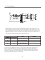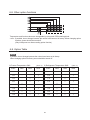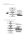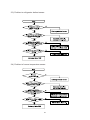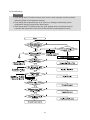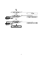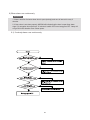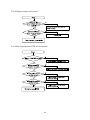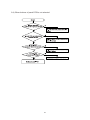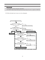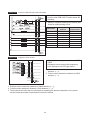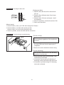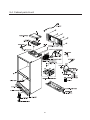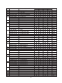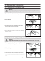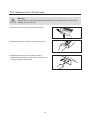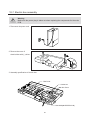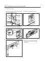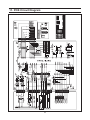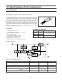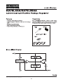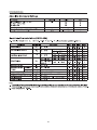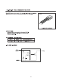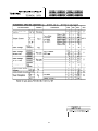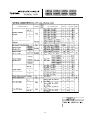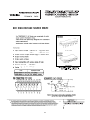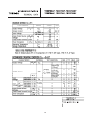
1
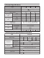
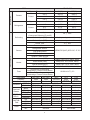
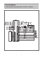
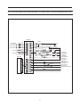
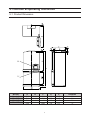
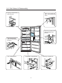
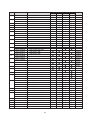
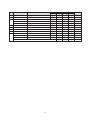
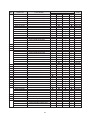
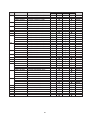
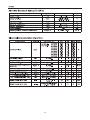
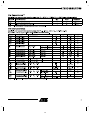
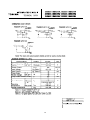
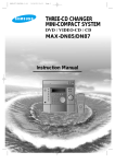
REFRIGERATOR
Model : SR-L677EV
SR-L679EV
SR-L627EV
SR-L629EV
GREEN
REFRIGERATOR
CONTENTS
1. Precautions
2. Product Specifications
3. Electrical Part Specifications & Standard
4. Circuit Diagram
5. Functions & Operating Instruction
6. Circuit Descriptions
7. Trouble shooting
8. Exploed View
9. Disassembly & Assembly
10. PCB Circuit Diagram
SR-L677EV
SR-L679EV
SR-L627EV
SR-L629EV
11. PCB Parts List
12. Specifications of Main Components
1. Precautions
Warning : Please abide by the following
precautions in order to conduct
the maintenance procedures in a
safety fashion.
Cleaning : After completing repairs, clean
the surrounding area and the
refrigerator and tell the consumer
about the repairs being made.
This appliance contains a small amount of the
refrigerant isobutane(R600a), a natural gas with high
environmental compatibility but which is also
combustible. When transporting and installing
the appliance, care should be taken to ensure
that no parts of the refrigerating circuit are damaged.
Refrigerant squirting out of the pipes could ignite or
cause an eye injury. If damage occurs nevertheless,
avoid any flames or potential sources of ignition, and
air the room in which the appliance is standing for
several minutes.
1-1. Caution when you replacing compressor.
• Do not smoke. Remove all the possible ignition
sources and then replace compressor in wellaired places.
• Don’t use welding machines if R600a refrigerant
does not exposed.
• In the case of gas leakage, always open the
windows.
• When cutting the SUCTION, DISCHARGE pipe
of the compressor, always take caution of the
inner pressure of the remaining gas.
• In order to avoid the creation of a flammable gas-air
mixture if a leak in the refrigerating circuit occurs, the size
of the room in which the appliance may be sited depends
upon the amount of refrigerant used. The room must be
1m3 in size for every 8 g of refrigerant R600a inside the
appliance. The amount of refrigerant contained in your
particular appliance is shown on the identification plate
inside the appliance.
• Never start up an appliance showing any signs damage. If
in doubt, consult your dealer.
1-2. Take out the power plug
• Always take out the power plug from the outlet
when doing repairs.
1-3. Be careful of electric shocks
• When inspecting the circuit, don’t touch the
battery charger and be careful of electric
shocks.
1-4. Use proper components
• Always use the component labeled in the
service component chart when replacing
components for repairs.
Refers to prohibition.
1-5. Use proper tools
Refers to prohibition of dismantling.
• Always use proper tools for repairs. If worn out
tools are used, it would cause defects in tuning
and electrical contact, leading to accidents.
Refers to prohibition of contact.
1-6. When doing repairs, inspect the POWER
Refers to guidelines which have to
be followed.
Refers to detaching the power plug
from the outlet.
Refers to earth connection for
preventing electric shocks.
CORD or whether there is fire in the lead wire
and make sure they are replaced.
1-7. Cutting of LEAD-WIRE
• For connecting the lead-wire that has been cut
off, use soldering or connector and always
disconnect the vinyl tapes.
1-8. Check for disconnection
• After completing the assembly, always measure
the disconnection resistance level, and turn on
the power after checking it is above 1MΩ.
Refers to possibility of death
or serious injury of a person.
1-9. Earth
Warning
• Check the status of earthing and repair the
incomplete ones.
1-10. Be careful of children
• There is always the possibility of danger when
doing repairs so make sure that children can’t
come nearby.
Caution
2
Refers to possibility of injury
of a person or damage to
property.
2. Product Specifications
Model
SR-L629EV SR-L679EV SR-L627EV SR-677EV
Type
LMF 2 Door
Freezer performance
(4-STAR)
Temperature control
Electronic control
Yes
Water dispenser
501(17.69) 551(19.46) 506(17.87) 556(19.63)
Total
Net Capacity
143(5.05)
Freezer
3
l/(ft )
161(5.68)
358(12.64) 390(13.77) 363(12.82) 395(13.95)
Total
526(18.57) 575(20.30) 531(18.75) 580(20.48)
Freezer
3
168(5.93)
Refrigerator
168(5.93)
185(6.53)
820 X 720 X 1790 (mm) (SR-L629(7)EV)
820 X 770 X 1790 (mm) (SR-L679(7)EV)
Cabinet insulation
CYCLO-PENTANE
Door insulation
CYCLO-PENTANE
Cabinet
A.B.S
Door
A.B.S
Liner
185(6.53)
358(12.64) 390(13.77) 363(12.82) 395(13.95)
Net dimension
(W X D X H)
Foam
143(5.05)
161(5.68)
Refrigerator
Gross Capacity
l/(ft )
No
Net weight
103Kg
108Kg
102Kg
107Kg
3. Electrical part specifications & standard
ITEM
STANDARD
Model
SR-L629EV, SR-L679EV, SR-L627EV, SR-L677EV
Rated Voltage
230-240V
230-240V
220V
Frequency
50HZ
50HZ
50-60HZ
60HZ
60HZ
SK190H-L2U
DK172P-L2U
(MK172P-L2U)
DK172C-L2U
(MK172C-L2U)
Model
MK4A3Q-L1U
Refrigerant
R600a
Oil Charge
2GSD(Mineral),
280cc
R134a
Freol α-15c(Ester), 265cc
Freol α-15c(Ester), 265cc
(Freol α-10c(Ester), 265cc)
Freezer
Split Fin & Tube Type
Refrigerator
Split Fin & Tube Type
Evaporator
Forced & Natural Convection Type
Condenser
Molecular Sieve XH-9
Dryer
Capillary tube
X L3500,
ID0.82
5.10kg/cm2
ID0.82 X L3000 4.64kg/cm2
BSBN(Brass screw)
Earth screw
Door switch
115V
RSCR
Starting type
Compressor
DK182Q-L2U
127V
DC12V
0.5A(S2PF101B)
3
AC250V 0.7A, AC125V 1.4A(SSD-6D)
ITEM
STANDARD
Temperature
Type
Freezer
F-Sensor
Type
Refrigerator
F-Sensor
Temperature Selection
ON(˚C)
OFF(˚C)
–25˚C
–23.5˚C
–26.5˚C
–19˚C
–17.5˚C
–20.5˚C
–14˚C
–12.5˚C
–15.5˚C
Temperature Selection
ON(˚C)
OFF(˚C)
1˚C
2.5˚C
–0.5˚C
4˚C
5.5˚C
2.5˚C
7˚C
8.5˚C
5.5˚C
First Defrost Cycle
4hr ± 10min
(Concurrent Defrost of F and R)
Defrosting
Defrost Cycle(FRE)
6 - 22hr(Vary according to the conditions used)
Defrost Cycle(REF)
6 - 11hr(Vary according to the conditions used)
Pause Time
10 ± 2min
Freezer-Sensor
Refrigerator-Sensor
Sensor
FRE Evap-Sensor
THERMISTOR (502AT), SPEC:5.0KΩ AT 25˚C
Electrical parts
REF Evap-Sensor
Ambient TEMP-Sensor
Heater
Defrost Heater(FRE)
242W (115V, 127V, 220V, 240V)
Drain Heater(FRE)
52W(115V, 127V, 220V, 240V)
Defrost Heater(REF)
120W(115V, 127V, 220V, 240V)
Drain Heater(REF)
38W(115V, 127V, 220V, 240V)
Thermal-Fuse for preventing
overheating of Freezer Defrost-Heater
AC250V 10A 77±5˚C
Fuse
Thermal-Fuse for preventing
overheating of Freezer Defrost-Heater
230-240V
230-240V
220V
127V
115V
Rated Voltage
Frequency
50Hz
50Hz
50-60Hz
60Hz
60Hz
DK172P-L2U
DK172C-L2U
Compressor
MK4A3Q-L1U
DK182Q-L2U
SK190H-L2U
(MK172P-L2U)
(MK172C-L2U)
RSCR
STARTING
Condenser
350VAC, 3.5㎌ 350VAC, 5.0㎌ 350VAC, 8.0㎌ 250VAC, 12㎌ 250VAC, 12㎌
RUNNING
4TM232PHBYY-53 4TM265RHBYY-53 4TM314RHBYY-53 4TM435PHBYY-53 4TM437RHBYY-53
MODEL
Over-Load
130±5
125±5
130±5
130±5
125±5
TEMP. ON
Protector
69±9
69±9
69±9
69±9
69±9
TEMP. OFF
J531Q35E330M385-2 J531Q35E330M385-2 J531Q34E220M3502 J531Q33E100M200-2 J531Q33E100M200-2
STARTINGMODEL
RELAY
33±20%
33±20%
22±20%
10±20%
10±20%
OPERATION
IS3210-SNL5C IS3210-SNL5C IS3210-SNF*B IS3210-SNP6D IS3210-SNP6D
FRE.
MOTORIS3208-SNL5B IS3208-SNL5B IS3208-SNF7D IS3208-SNP6H IS3208-SNP6H
REF.
FAN
IS3208-SCL5A IS3208-SCL5A IS3208-SCF7A IS3208-SC06A IS3208-SCH6A
CIRCUIT
110V-130V/15W
240V/15W
FRE.
LAMP
110V-130/30W
240V/25W
REF.
4
4. Circuit Diagram
4-1. 230V-240V/50Hz, 220v/50Hz,60Hz, 127V/60Hz, 115V/60Hz
5
4-2. 230V-240V/50Hz, 60Hz, 220V/50Hz,60Hz, 127V/60Hz, 50Hz, 115V/50V,60Hz(INVERTER PCB)
MAIN PCB
CN10
CN30
F-ROOM SENSOR
R-ROOM SENSOR
DEFROST SENSOR.F
DEFROST SENSOR.R
BLK
YEL
BLK
ORG
BLK
PRP
BLK
GRY
RUNNING CAPACITOR
BRN
3
PTC
5
S/BLU
S
F-DRAIN HEATER
DEFROST HEATER.R
R-DRAIN HEATER
YEL
CN50
BLK
BRN CN71
REF
ORG
YEL
PNK
BLU
PRP
F-THERMAL FUSE
R-THERMAL FUSE
R/LAMP INVERTER
FLUORESCENT LAMP
R-ROOM FAN
ORG
R-LAMP HEATER
BLU
F-ROOM FAN
PNK
GRY
WHT
COMPRESSOR
C
1
3
O.L.P
2
COMP COOLING FAN
GRY
W/BLK
M
DEFROST HEATER.F
WHT
PANEL PCB
A
6
BRN
WHT
R-DOOR S/W
E
GRY
2
S/BLU
N
THERMAL FUSE
CN70
BLK
F-DOOR S/W
DC TRANS
BLU
F-ROOM LAMP
RED
S/BLU
6
BLU-BLUE
BRN-BROWN
E-EARTH
GRY-GRAY
ORG-ORANGE
PNK-PINK
PRP-PURPLE
RED-RED
S/BLU-SKY BLUE
WHT-WHITE
YEL-YELLOW
BLK-BLACK
W/BLK-WHITE/BLACK
5. Function & Operating Instruction
5-1. Product Dimension
"X"
"Y"
MODEL
A
B
C
D
E
Remarks
SR-L679EV
SR-L677EV
SR-L629EV
SR-L627EV
1790
1790
1790
1790
1013.5
1013.5
1013.5
1013.5
1508
1508
1458
1458
755
755
705
705
667
667
617
617
"X"
"Y"
"X"
"Y"
7
5-2. Part Name & Disassembly
• Top tray disassembly
Take out food stuffs and
pull it out by following the
arrow.
Pull it forward.
•
Take out the water bottle
with the bottom lever
pressed.
•
•
•
• Tray disassembly
•
Pull it out by following
the arrow.
•
•
• Ice compartment
• Vegetable compartment
8
• Freezing compartment
5-3. Circulation of Refrigerant (H.M CYCLE)
Compressor → Sub condenser → Cluster pipe → Hot pipe → Dryer → Capillary tube
→ R-Evaporator → F-Evaporator → Accumulator → Suction pipe → Compressor
9
5-4. Cool Air Circulation
10
5-5. Temperature Control and Other Capacity Explanation
1. Display design
2. Temperature control function
1) Temperature selection of freezer compartment
❈ After the initial key selection, it displays the notch which is presently set up, then within 5
seconds re-memorize the key after 1-2) points mentioned below. If there is no input of the
key, it moves back to the previous temperature display.
1-1) From -14˚C ~ -25˚C, each one key is selected in 1˚C interval.
1-2) Selection key operation for Freezer is set up orderly.
1-3) Actual temperature is indicated during both Power-On and electrical failure.
1-4) Standard temperature of each stage is as follows.(standard for 1/3 height)
Stage
Temperature
1
2
3
4
5
6
7
8
9
10
11
12
-14˚C -15˚C -16˚C -17˚C -18˚C -19˚C -20˚C -21˚C -22˚C -23˚C -24˚C -25˚C
1-5) After key input, seven-segment indication changes immediately but actual function
operates after 10seconds.
2) Temperature selection of refrigerator compartment
2-1) From 7˚C ~ 1˚C, each one key is selected in 1˚C interval.
2-2) After the initial key selection, the former selected temperature is displayed, and within
5seconds temperature selection alters as in 2-3), and when final key input is done, the
final key input temperature converse into a set point after 10 seconds.
2-3) Set up is established orderly according to operation of selection button.
2-4) Actual temperature is indicated during both Power-On and electrical failure.
2-5) Standard temperature of each stage is as follows.(standard for 1/3 height)
Stage
1
2
3
4
5
6
7
Temperature
7˚C
6˚C
5˚C
4˚C
3˚C
2˚C
1˚C
2-6) After key input seven-segment indication changes immediately but actual function
operates after 10seconds.
11
3) Quick freeze
3-1) Press the on/off buttons of Quick Freeze so that the lamp of Quick Freeze is light up and
off and then it operates it’s function automatically.
3-2) It does not indicate from initial Power on.
Change of
light indication
Initial Power On
Off
Pressed once time
Quick Freeze On
Pressed second time
Remark
Off
a) When Quick Freeze is selected, LED indication will immediately change but actual
operation operates after 10 seconds. (COMP and FAN operates continuously for 2 hours
and 30 minutes and it switches off automatically.)
b) When Quick Freeze is selected, it will operate unconditionally without considering the
temperature of freezer compartment.
c) During the operation, the temperature of refrigerator compartment is controlled
automatically by the selected temperature.
d) Temperature display of freezer displays actual temperature.
4) Quick cool.
4-1) Press the on/off buttons of Quick Cool so that the lamp of Quick Cool is light up and off
then it operates its function automatically.
4-2) It does not indicate from initial Power on.
Change of
light indication
Inition Power On
Off
Pressed Once time
Quick Cool On
Pressed second time
Remark
Off
a) When Quick Cool is selected, LED indication will immediately change but actual operation
operates after 10 seconds.
b) When Quick Cool is selected, COMP and R-Fan are operate until the temperature of
refrigerator compartment reached -2°C but the maximum operation time of Quick Cool is 2
hours and 30 minutes. So that, it switches off automatically after 2 hours and 30 minutes.
c) During the operation, the temperature of freezer compartment is controlled automatically
by the selected temperature.
d) Temperature display of refrigerator displays actual temperature.
❈ If you press Quick Freeze and Quick Cool button concurrently, each function operates
independently.
Reference
If you choose Quick Freeze or Quick Cool when freezer temperature is more than -10°C and
refrigerator temperature is above +10°C just as the initial Power On Condition, it operates
differently from what is mentioned above, and this is an exceptional case.
12
5) Sabbath function
5-1) It will turn to sabbath function if you press freezer and refrigerator temperatune button
together for 5 seconds.
5-2) When turned to sabbath function, all of the front display of LED turn off.
5-3) The light will not switch on even when the door is opened, and if it was switched on then
it will switch off.
5-4) To cancel the operation, you have to press freezer and refrigerator temperature button
together again for 5 seconds.
❈ This function is used only in special area.
3. Buzzer alarm function
1) Touch button type (ding-dong sound)
1-1) there is "ding-dong" sound to confirm input periodically for each one second for button
operation in each control panel.
1-2) key recognition is within 0.2 sec and "ding" sound beeps in continuous key recognition.
1-3) key recognition sound will first activate in other information.
2. Alarm when door is open
2-1)Alarm melody will run if door of freezer or refrigerator is open for 2 minutes or more.
2-2) If door continue to remain open alarm will run periodically.
2-3) Alarm will immediately stop when door is closed.
3. Forced running alarm and forced defrost alarm (beep sound).
3-1) If forced running, or defrost is chosen, there is a beep sound.
3-2) Once you press forced running test button, it will beep until you choose cancellation or it
cancel automatically (0.25sec ON/0.75sec OFF)
3-3) It will beep even during defrost is complete (include paused time) or until cancel button is
pressed.
3-4) During forced running alarm runs 0.1sec on and 1sec off, and during forced defrost alarm
runs as well 0.5sec on and 0.5sec off.
4. Defrost function
1) Once power is on and COMP is ON for 4 hours, both refrigerator and freezer starts to defrost
at the same time.
2) When the defrost time is reached, F-Fan and COMP runs pre-cooling for 20 minutes and
starts heating activity then the pause time is operated about 8 ~12 minutes(10±2minutes).
3) Actual defrost period is from minimum 6 hours up to maximum 11 hours, and freezer
compartment defrost period is from min. 12 hours up to max. 22 hours instantaneously
(COMP ON for additional period).
4) The decision of defrost period is maded by the ambient temperature and the count of door
open and the length of door open time.
5) Defrost periods memorize these information at MICOM as a case per hour. Therefore, case
of defrost period distinguishes per hour.
6) Influences of count and length of door open for time distinguisher get checked from the door
switchs of refrigerator compartment and freezer compartment.
7) If refrigerator compartment temperature is over trset -on+6˚C (at ambient temp. is over 21˚C)
or trset-on+2˚C (at ambient temp is over 33˚C), COMP is runned by refrigerator
compartrment temperature. In this case, the defrost heater of refrigerator compartment starts
after 2 hours running of COMP.
8) After 7) is proceeded, the concurrent defrosting of freezer and refrigerator start after 4 hours
4 hours running of COMP.
9) If defrost operation is reached during quick freeze operation, quick freezer operation is
finished first and then defrost operation is proceeded.
13
5. Test function
❈ Test function is for the test of PCB, product, official inspection and ability of SVC.
❈ When s/w test is chosen and tested the product, you switch off and on again then let it run a
self-test.
1) Function of forced running.
1-1) If you choose PCB button once, COMP will automatically start.
1-2) When forced running is chosen, freezer will show “FF” and “1” in refrigerator automatically.
when this option is selected and 1 minute is past, temperature memorized will not change
even if you select defrost or cancel test activation (maintains F:-25˚C and R:1˚C).
1-3) Forced running will activate only for 24 hours in full-down operation. Freezer and
refrigerator will automatically activate.
1-4) To cancel forced running power is off and on again or select test cancel mode.
1-5) During forced running alarm (0.25sec ON/ 0.75 sec OFF) runs until it is completed. The
alarm will continue without alarm key selection.
1-6) When forced running is selected, quick freeze operation does not activate.
2) Forced defrost function
2-1) When you press test button once more during forced running refrigerator compartment
activates defrost.(R-defrost only)
2-2) If you press button once more, freezer defrost will start at the same time with refrigerator.
2-3) If forced defrost function is selected, forced running will automatically cancel. And after
forced defrost is completed, it will proceed normal operation.
3) Test cancel mode
3-1) When you press test button once more during forced defrost in freezer and refrigerator, it
proceeds normal operation.
3-2) Alarm will stop during test cancel mode.
6. Function of initial Power ON
1) When power ON, refrigerator proceed initial self-test and, if normal, it indicate LED in all
operation panel for 2 seconds.
2) When proceeding self-test and if temperature sensor finds fault sensor, LED displays the
relatecl LED(see table 1.) for periods of 0.5 sec of related LED.
3) Switch on all LED for 2 sec. Initial display of freezer and refriger show actual temperature.
4) Keep condition of R-defrost heater and F-defrost heater for 3 sec for interval of 0.5 sec.
5) If F and R- defrost is finished at initial condition, COMP, F-fan and R-fan activates intervals
with 0.5 sec without inner temperature condition.
7. Power failure compensating function
1) function of notch save.
1-1) When you press quick freeze, quick cool, freezer, refrigerator button, micom save present
operating and display condition. Once the power is re-instated, the appliance will continue
to operate at the most recent temperature setting (except test mode.)
1-2) 1-1) Activity proceeds when F-evap. and R-evap. Temperature is below 10˚C added
together at initial power ON, it will activate, and if its more than 10˚C it goes back to initial
mode activity. Quick freeze, quick cool and Sabbath function get not selected.
1-3) If power gets off during quick freeze, quick cool or sabbath function and then the power is
re-instated, the appliance will proceed quick freeze or quick cool function again at least
one of F-evap. or R-evap. temperature is below 10˚C.
14
❈ Exhibition mode
1. When you press quick freeze button and freezer temp. button together the operation changes
into exhibition mode.
2. In exhibition mode, compressor is immediately off and defrost do not activate.
3. If you press quick freeze button and freezer temp. button together for 5 sec exhibition mode
cancel out and bact to nomal operation.
8. Self-test function
1) Define of the fault temperature sensor : temperature of the sensor is over between -50˚C
(4.5volt) ~ +50˚C(0.5volt)
1-1) Self-test fuction due to power ON.
a) When a power is ON, it internal MICOM will decide faulty in temperature within 1 sec.
b) If faulty sensor is found, the “related display LED” switches on and off for 0.5 sec
intervals. And it will not beep (refer to self-test faulty indication table).
c) At the LED situation is the faulty sensor display, self-test function key ( press quick
freezer and quick cool button for 5 sec) is the control of normal temperature is delayed.
d) Fixing default sensor when there is an error, or press quick freeze and quick cool button
for 5 sec., it automatically cancel and activate normally.
2) Self-test function during normal activation
a) During normal activation, if you press quick freeze and quick cool key together for 3 sec.
temperature selection display of all ON/ OFF show for 2 sec by 0.5 intervals. Including
this 2 sec, press quick freeze and quick cool button together for 5 sec then it select selftest function.
b) If there is ding-dong sound it change into self-test function. If you press refrigerator temp.
selection button during 2 sec display toggle, it proceeds as the display function of the
presently operating parts.
c) If there is an error of the sensor, display of the faulty sensor continue for 30 sec then
activate normally (ding-dong alarm activates).
d) Button selecting is not selected during self-test proceeding.
15
Table 1. Display table of self diagnosis.
No
1
2
3
4
5
Item
Display LED
Symptom
Remark
R-sensor
Refrigerator
• Open faulty
• Short faulty
•Suspected to be below -50˚C
•Suspected to be over +50˚C
R-area
defroster
sensor
Refrigerator
• Open faulty
• Short faulty
•Suspected to be below -50˚C
•Suspected to be over +50˚C
Outer sensor Freezer
• Open faulty
• Short faulty
•Suspected to be below -50˚C
•Suspected to be over +50˚C
F-sensor
Freezer
• Open faulty
• Short faulty
•Suspected to be below -50˚C
•Suspected to be over +50˚C
F-area
defroster
sensor
Freezer
• Open faulty
• Short faulty
•Suspected to be below -50˚C
•Suspected to be over +50˚C
9. Display function of the presently operating parts.
1) If you press quick freeze and quick cool button together for 3 sec during normal operation,
LED display refrigerator and freezer temperature will show ON/OFF for 2 sec at interval of
0.5 sec
16
2) At this moment if you take off quick freeze and quick cool button and press refrigerator temp.
button (ding-dong sound), it change into the display of the presently operating parts.
3) This display condition is unrelated to actual operation and it is an reference of indication that
MICOM commanded operating order).
Table 2. Display table of the presently operating parts.
No
Content
1
2
3
4
5
6
7
8
9
10
11
12
R-fan
R-defrost heater
Initial start mode
Over load mode
Low temp.mode
Exhibition mode
Comp
F-fan
F-defrost heater
F-Lamp
R-Lamp
Normal mode
Display LED
Operation
1 st letter “a” led in refrigerator
1 st letter “c” led in refrigerator
1 st letter “d” led in refrigerator
1 st letter “e” led in refrigerator
1 st letter “f” led in refrigerator
1 st letter “g” led in refrigerator
1 st letter “a” led in freezer
1 st letter “b” led in freezer
1 st letter “d” led in freezer
1 st letter “a” led in freezer
1 st letter “b” led in freezer
1 st letter “e”, ”f” led off in refrigerator
Include R-fan activation
Defrost heater activation
Initial power is switched ON
Outer temperature is over 35˚C
Outer temperature is below 20˚C
Exhibition mode is operated together
Led ON when COMP activation is included
Led ON F-fan activation is included
Led ON when F-heater activation is included
Led ON when F-lamp activation is included
Led ON when R-lamp activation is included
Out temperature is about 21˚C~34˚C
Remark
Ref. 6.button scan
and display circuitry
(see page 21)
10. Actual temperature and selected temperature in display function
1) Initial power ON
1-1) When initial power On is set, it reads both inner temperature of freezer and refrigerator.
Display range of freezer is -35˚C~+30˚C and refrigerator -9˚C~+9˚C.
1-2) After this, if freezer inner temperature of a trset_off+1˚C above is recognized at least once,
LED display of freezer will change into a set-up temperature. And if refrigerator inner
temperature of trset_ off +3.5˚C above is recognized at least once, LED display of
refrigerator will change into a set-up temperatures. After all this, if freezer inner
temperature is above 0˚C and refrigerator inner temperature above +15˚C it will proceed
display blinking. But blinking operation only starts 10 minutes after it senses its problem
with inner temperature.
1-3) During the actual temp. dispaly condition, you choose quick freeze or quick cool function
the LED display will display actual temperature.
2) Stability in inner temperature
2-1) After selected temp. is reached, freezer and refrigerator display the selected temp.
a) If freezer inner temperature is above 0˚C for 10 minute, the display of the selected temp.
will blink.
b) If refrigerator inner temperature is above 15˚C for 10 minute, the display of the selected
temp. will blink.
c) When quick freeze is chosen, only freezer display will display actual temperature and the
actual temperature displays up to -35˚C.
17
3) Door open
when door is open, the related display shows an actual temperature.
3-1) Display range of freezer is -35˚C ~ 30˚C and refrigerator is -9˚C~9˚C.
3-2) If freezer inner temperature is above 0˚C for 10 minute, the display of the selected temp.
will blink.
3-3) If refrigerator inner temperature is above 15˚C for 10 minute, the display of the selected
temp. will blink.
3-4) When door is open, 1˚C will increase after delay time from the display before door
opens. When door close, 1˚C will decrease after delay time if there is a change in inner
temperature. Temperature will reach up to presently selected notch.
4) Defrost Display function
4-1) If defrost starts both freezer and refrigerator display the selected temperature. So it will
not blink for 2 hours even if it sensed faulty in inner temperature, after 2 hours it will
decide to blink or not.
Reference
State of COMP cooling fan according to the ambient temperature (When COMP. is re-started)
- always OFF COMP cooling fan when ambient temperature is below 5˚C.
- COMP cooling fan always switch ON after 9 minute when ambient temperature is 6˚C~10˚C.
- COMP cooling fan always switch ON after 6 minute when ambient temperature is 11˚C~15˚C.
- COMP cooling fan always switch ON after 3 minute when ambient temperature is 16˚C~21˚C.
- COMP cooling fan always switch ON when ambient temperature is over 21˚C.
(PCB Part List)
NO
CODE NO
1
2
3
4
5
6
7
8
9
10
11
12
13
DA41-00099A
DA41-00099B
DA41-00102A
DA26-30111H
DA26-30111F
DA26-30111C
DA32-00006C
DA32-00006C
DA32-10109H
DA32-10105A
DA41-00013B
DA41-20160A
DA41-20148A
ITEM
PBA MAIN
PBA MAIN
PBAPANEL
DC TRANS
F, R DEF SENSOR
F, R DEF SENSOR
R SENSOR
F SENSOR
INVERTER PCB
SPEC
W2 PJT
W2 PJT
W2 PJT
220~240V/50, 60Hz
105V/50,60Hz
127V/50,60Hz
PX-41C
PX-41C
PX-41C
PX-41C
220~240V/50,60Hz
127V/50,60Hz
105~115V/50,60Hz
Q’ty
1
1
1
1
1
1
1
1
1
1
1
1
1
Remark
AHAM OPTION
Different
according to the
source of power
Different
according to the
source of power
❈ code for temperature might change due to after the progress in development in products
18
6. Circuit Descriptions
6-1. Power circuit
Circuit used
Voltage
(DC 12V)
Relay Operation & LED Display
Vcc (DC 5V)
Power around MICOM & Sensor Detector
1) The input AC voltage of DC-trans secondary registers 8V at CN10 between ①~③. The rectified
voltage passed through D101 ~ 104 becomes DC 5V through voltage regulator MC7805(REG1).
The power(DC5V) is supplied to the power around micom and sensor detector.
2) The input AC Voltage of DC-trans secondary registers 15V at CN10 between ⑤~⑦. The rectified
voltage passed throush D105 ~ D108 becomes DC 12V through voltage regulator MC7812CT
(REG2). The power (DC12V) is supplied to the relay operation and LED display.
19
6-2. Oscillator
Port
Oscillating Frequency
Xin(#19)
4.00MHz
Xout(#20)
4.00MHz
It is designed for clock generation and time
calculation for synchronizing transmission and
reception on the logic elements inside the MICOM.
If the X-TAL specification changes, MICOM may
make an error.
(The standard components should be used.)
±0.5% Error
6-3. Reset Circuit
Port
Voltage
Vcc
5V
Reset
5V
When power is supplied to MICOM, reset circuit
initializes RAM and other parts on MICOM to
initialize all programs. Reset voltage maintains “low”
for hundreds of µsec comparing to MICOM Vcc
voltage when power is input. It also maintains
“high”(5V) during normal operation. But, when Vcc
drops to 3.4V-3.7V, reset port becomes “low”.
6-4. Door S/W Detector
20
DOOR
Door Conditions
Door S/W Contact
MICOM
PIN NO
Micom Input Voltage
“HIGH”
CLOSE
OPEN
OPEN
CLOSE
“LOW”
CLOSE
OPEN
“HIGH”
OPEN
CLOSE
F
# 39
R
# 40
“LOW”
1) If door is open, door S/W contact is closed. Then MICOM receives “low” signal and detects
door open then, Relay control circuit receives “HIGH” signal and turn Lamp on.
2) If door is closed, door S/W contact is open. Then MICOM receives “high” signal and detects
door close then, Relay control circuit receives “LOW” signal and turn Lamp off.
6-5. Temperature Sensor
( Air Sensor)
When Sensor is open
When sensor is cut off
MICOM input “HIGH”
MICOM input “LOW”
1) The sensor uses the characteristics of thermistor. If temperature goes higher, resistance goes
lower. On the contrary, if temperature goes lower, resistance goes higher.
2) MICOM input voltage is counted by sensor as follows.
RTH
(VCC : 5V, RTH : Sensor reisitance)
VF =
X Vcc
RTH + R301
3) For the resistance information on temperature and MICOM input voltage, please refer the
conversion table. (Page. 41)
21
6-6. Button scan and display circuitry
At that time, the peak to peak voltage of square signal registers around 12V. The grid #1 ~#5
waveforms are as follows.
22
6-7. Load Operation
If MICOM outputs “high” signal to driver-IC(KID65003AP/S1P2655AØ3) according to each load
operation conditions, IC turns on and DC 12V flows to ground through the relevant relay coil. Then,
core is magnetized by the coil current, and relay contact switches on. When relay contact is on, AC
POWER is supplied to the relevant operation load, then which will be activated. If MICOM outputs
“low” signal, load operation stops with the relevant relay contact off.
RELAY
Load
Remark
off
Comp Operation
Defrost-Heater Power Off
on
on
Comp off, Defrost-Heater Off
off
on
Defrost-Heater On
off
off
Comp Off, Defrost-Heater Off
COMP
Defrost Heater
on
Comp Power Off
Like the above block diagram, operation of F, R defrost heater is detervminedy according to the
operation of relay for COMP. When comp relay is connected to NO terminal, comp operates.
However, in case of F, R defrost heater, electricity dose not pass through the heater though relay
works, But, if Comp relay is connected to NC terminal, comp does not operate and heater gets
electrieity according to operation of F, R defrost relay.
23
6-8. Other option functions
Temperature and function values are changeable by using main PCB switching diode.
• Note : If possible, do not change because the values have been set in factory. When changing option
functions, power should be turned off.
(Only initial power-on allows reading option function)
6-9. Option Table
NOTE
If possible, do not change because the values have been set in factory.
When changing option funcfions, power should be turned off.
1) Freezer Temperature Shift
(Unit ˚C)
2) Refrigerator Temperature Shift
(Unit ˚C)
SHIFT
D601
D602
D603
SHIFT
D604
D605
D606
Reference
-
-
-
Reference
-
-
-
-0.5
-
-
•
-0.5
-
-
•
-1.0
-
-2.0
-
-3.0
+1.0
+2.0
+3.0
•
•
•
•
•
•
-
-1.0
-
•
-2.0
-
-
-
-3.0
-
•
+1.0
-
+2.0
•
+3.0
•
•
24
•
•
•
•
•
•
•
-
-
-
•
•
•
-
-
•
7. Trouble shooting
Precautions
1. Is the power cord well connected to wall outlet?
2. Refer to the reference
1) No power
Start
DC-Trans primary
power input?
N
Check wires
Y
DC-Trans secondary
power input?
Y
DC 12V output
from REG102?
N
Replace DC-Trans
N
Check REG102
(MC7812)
Y
DC 5V output
from REG1?
N
Check REG1
(KA7805)
Y
Are wires connected to
panel securely?
N
Check wire connection
Y
Reference 1
(Page. 38)
Panel PCB Ass’y
is OK?
N
Replace panel PCB
Y
Exchange main PCB
25
2) Problem with self-test
2-1) Problem with outside temperature sensor
2-2) Problem with refrigerator temperature sensor
26
2-3) Problem in refrigerator defrost sensor
2-4) Problem in freezer temperature sensor
27
2-5) Problem in freezer defrost sensor
28
3) Compressor does not run
Reference
1. Compressor does not operate in 5 minutes after compressor OFF.
2. Compressor does not run during defrosting.
3. Compressor does not run because low temperature is detected if freezer and refrigerator
sensor is not connected.
29
4) When cooling fan do not activate
Reference
Check cooling fan when defrost activation is selected.
1. When COMP is OFF both freezer and refrigerator cooling fan plus COMP cooling fan
remain OFF.
2 . When COMP is ON, refrigerator fan is not always ON and when refrigerator
temperature reached to a set-up temperature fan goes OFF.
3. When both freezer and refrigerator door close from open each fan takes delay time
(5sec~ 1 min) and running. (COMP ON as a condition)
4-1) When freezer fan (f-fan) do not activate
30
4-2) When refrigerator fan (R-fan) do not activate
31
4-3) When COMP cooling fan do not activate
32
5) No defrosting
Reference
1. Even though both F·R-defrost sensors short-circuit, normal operation continues without
defrosting.(Refer to self-diagnosis function)
2. Even though the temperature fuse is off, there is no heating but defrosting natural
temperature increase comp off-time takes longer.
3. Even though both F·R-defrost sensor are open, heating does not end and comp-off
maintains with temperature fuse short-circuited.(Refer to self-diagnosis function)
33
34
6) When alarm run continuously
Reference
1. Alarm runs after 2 minute when door is open (melody) and runs in interval in every 2
minutes.
2. If door close is not done properly, MICOM will indicate that the door is open then alarm
rings. If it recognize door open over 10 minutes it switch OFF inner lamp goes OFF. Lamp will
not go ON in this situation even if door opens.
6-1) If melody alarm runs continuously
35
6-2) If Beep sounds continuously
6-3) When original panel PCB do not activate
36
6-4) When buttons of panel PCB is not selected
37
Reference
1. Is the power cord well connected to wall outlet?
2. Be careful of high-voltage discharge because high voltage DC power is supplied to SUB-PCB.
6-5) When the light dosen’t come on in the refrigerator
Start
N
Is door switch normal?
Replace door switch, check main wire
Y
N
Is main pcb relay
normal(RY75)?
Check relay, exchange main pcb
Y
Fluorescent LAMP(SUB PCB)
Exchange LAMP
Is power suppling to
SUB PCB input?
N
Check connector and wire
Y
Is power suppling to
DC part C2 of rectifier?
N
Check SUB PCB power input
Y
Fluorescent LAMP
normal?
N
Exchange LAMP
Y
Exchange SUB PCB
38
8. Reference
Reference1
The connection of DOOR-CABI
Reference2
Inspection of Relay
* First separate the housing connected to the
main PCB CN70, 71 and measure the
following items.
1. Measure the coil bisection of the relay and
check whether it works.
2. Measure the apex bisection for open circuit.
Apex category The voltage of
Judging the
coil bisection apex bisection
DC 12V(Operation)
Apex 3
DC 0V(Standstill)
Apex 2
DC 12V(Operation)
DC 0V(Standstill)
C-NO:SHORT
C-NC:OPEN
C-NO:OPEN
C-NO:SHORT
SHORT
OPEN
Note) C → Common, NO → Normal open, NC → Normal close
3. When it operates as above, it is normal and
when it does not operate, report the
corresponding relay.
39
Reference3
Check for malfunctioning of the subordinate
* Cut off the power code, separate the housing
from the main PCB CN70,71 and measure the
following.
1. Measure resistance between the terminals and
check for malfunctioning of L/W.
Subordinate
R Defrost heater
F Defrost heater
Comp
Comp-circulation fan
R-Circulation fan
F-Circulation fan
R-Lamp
F-Lamp
Reference4
Measurement Evaluation of meaterminal
surement result
CN70 ⑤ - ①
CN70 ⑦ - ①
CN70 ⑨ - ①
CN71 ⑦ - ①
CN71 ⑤ - ①
CN70 ③ - ①
CN71 ⑨ - ①
CN71 ③ - ①
Inspection of the sensor
* Separate the housing connected to main PCB
CN30.
* Resistance value lowers while temperature
rises, because it is a NTC type sensor.
1. R sensor measures resistance of CN30
between ②~⑤.
2. Freezer sensor measures resistance of CN30
between ①~⑤.
3. R-defrost sensor measures resistance of CN30 between ④~⑤.
4. F-defrost sensor measures resistance CN30 between ③~⑤.
5. The measurement value above is calculated by comparing the present temperature of the sensor
and the temperature table in specification found in the manual.
40
Reference5
Checking the Door S/W
(Refrigerator Bulb)
1. Open the door and check if the freezer bulb
turns on.
2. Press the Door S/W and check if the freezer
bulb turns off.
3. Close the door of freezer and repeat 1 and 2
for refrigerator.
4. If there is a problem, check bulb and door S/W.
5. Check wire connection.
(Micom signal)
1. Check if CN30 ⑥ and ⑧ is 5V DC after closing the F·R doors.
2. Check if CN30 ⑥ is 0V DC when opening F door.
2. Check if CN30 ⑧ is 0V DC when opening R door.
3. If there is problem, check door S/W and wire connection.
Reference6
Forced running & forced defrosting
(Forced running)
* This function is used to turn on the comp and
fan immediately regardless of the temperature
of freezer.
1. Press the button on the PCB after removing
the main PCB cover from the upper part of
refrigerator.
2. Buzzer will sound to indicate the forced running.
(Forced defrosting)
* This function is used to turn on the defrosting
regardless of defrost time.
1. Press the button during forced running. Then,
R-defrosting is performed.
2. If the button is press during R-defrosting, Fdefrosting is also performed at the same time.
3. If the button is pressed during R-F defrosting,
test mode is released.
41
Reference7
Sensor resistance and voltage conversion table for temperature
(Sensor pressure voltage 10KΩ – Voltage converted by the F-reference)
* Voltage conversion table depends on H/W structure of MICOM port input voltage.
Sensor Short : Micom 0V.
Sensor Open : Micom 5V.
※ Sensor partial pressure resistance 10KΩ
TEMP. Resistance KΩ±1% Voltage(V)
TEMP. Resistance KΩ±1% Voltage(V)
TEMP. Resistance KΩ±1% Voltage(V)
– 35
68.648
4.364
– 13
22.832
3.477
9
9.016
2.37
– 34
65.011
4.333
– 12
21.814
3.428
10
8.673
2.322
– 33
61.595
4.301
– 11
20.848
3.379
11
8.345
2.274
– 32
58.384
4.268
– 10
19.932
3.329
12
8.032
2.227
– 31
55.366
4.235
–9
19.062
3.279
13
7.732
2.18
– 30
52.526
4.2
–8
18.237
3.229
14
7.446
2.134
– 29
49.854
4.164
–7
17.453
3.178
15
7.172
2.088
– 28
47.337
4.127
–6
16.709
3.127
16
6.910
2.043
– 27
44.967
4.09
–5
16.001
3.076
17
6.659
1.998
– 26
42.733
4.051
–4
15.328
3.025
18
6.420
1.954
– 25
40.626
4.012
–3
14.688
2.974
19
6.190
1.911
– 24
38.640
3.972
–2
14.080
2.923
20
5.970
1.869
– 23
36.765
3.93
–1
14.501
2.872
21
5.759
1.786
– 22
34.995
3.888
0
12.949
2.821
22
5.557
1.786
– 21
33.323
3.845
1
12.424
2.77
23
5.363
1.745
– 20
31.743
3.802
2
11.924
2.719
24
5.178
1.705
– 19
30.250
3.757
3
11.447
2.668
25
5.000
1.666
– 18
28.838
3.712
4
10.993
2.618
26
4.829
1.628
– 17
27.502
3.666
5
10.559
2.567
27
4.665
1.59
– 16
26.237
3.62
6
10.146
2.518
28
4.508
1.553
– 15
25.040
3.573
7
9.752
2.468
29
4.357
1.517
– 14
23.906
3.525
8
9.375
2.419
30
4.212
1.481
42
9. Exploed View
9-1. Freezer room
43
OPTION
NO
CODE-NO
PART NAME
1
2
3
DA67-40203N
DA67-40182A
DA63-00946A
DA63-00946B
DA63-00947A
DA63-00947B
DA63-00948A
DA63-00948B
DA66-10104A
DA71-20145A
DA63-00904A
DA63-00922A
DA97-00181A
DA97-00192C
DA97-00192D
DA97-00192E
DA97-00192F
DA47-00095E
DA32-00006C
DA97-00122A
DA97-00122B
DA97-00122C
DA97-00122D
DA61-70114B
DA61-70115C
DA63-40006A
DA63-00924A
DA63-00923A
DA47-40112N
DA31-10105A
4713-000213
4713-001035
DA63-00941A
DA97-00390A
DA97-00390B
DA97-00390C
DA63-00903A
DA61-00081A
DA31-00019A
DA31-00002P
DA31-00002W
DA31-00002X
DA31-00002V
DA97-00195B
DA97-00195C
DA97-00195D
DA97-00195E
TRAY-ICE,ASSY
TRAY ICE
TRAY-FRE UPP,ASSY
TRAY-FRE UPP,ASSY
TRAY-FRE MID,ASSY
TRAY-FRE MID,ASSY
TRAY-FRE LOW,ASSY
TRAY-FRE LOW,ASSY
ROLLER FRE
FIXER ROLLER
TRAY ICE CUBE
TRAY ICE CUBE
COVER EVAP FR(FRE),ASSY
EVAP-FRE ASSY
EVAP-FRE ASSY
EVAP-FRE ASSY
EVAP-FRE ASSY
ASS’Y-FUSE THERMO(77˚C)
SENSOR ASSY
ASSY SUPT-FREE
ASSY SUPT-FREE
ASSY SUPT-FREE
ASSY SUPT-FREE
SUPPORT-FREE,L
SUPPORT-FREE,R
GROMMET RAIL
COVER-LAMP,FRE
COVER-LAMP,FRE
LAMP HOLDER
SENSOR ASSY
LAMP-INCANDESCENT
LAMP-INCANDESCENT
COVER-EVAP RE(FRE),ASSY
COVER-EVAP RE(FRE),ASSY
COVER-EVAP RE(FRE),ASSY
COVER-EVAP RE(FRE),ASSY
COVER-EVAP REAR
CASE-MOTOR
FAN-PROPELLER
MOTOR-FAN
MOTOR-FAN
MOTOR-FAN
MOTOR-FAN
DRAIN PLATE FRE ASSY
DRAIN PLATE FRE ASSY
DRAIN PLATE FRE ASSY
DRAIN PLATE FRE ASSY
4
5
6
7
8
9
10
11
12
13
14
15
16
17
18
19
20
21
22
23
24
25
26
44
SR-L627
SR-L629
SR-L677
SR-L679
●
●
●
●
●
●
●
●
●
●
●
●
●
●
●
●
●
●
●
●
●
●
●
●
●
●
●
●
●
●
●
●
●
●
●
●
●
●
●
●
●
●
●
●
●
●
●
●
●
●
●
●
●
●
●
●
●
●
●
●
●
●
●
●
●
●
●
●
●
●
●
●
●
●
●
●
●
●
●
●
●
●
●
●
●
●
●
SPEC
●
●
●
●
●
●
●
●
●
●
●
●
●
●
●
●
●
●
●
●
●
●
●
●
●
●
●
●
●
●
●
●
●
●
●
●
●
●
●
●
●
●
●
●
●
●
●
●
●
●
●
●
●
●
●
●
●
●
●
●
●
●
●
●
●
●
●
●
●
●
●
240V
220V
127V
115V
EVAP FRE.250V
EVAP FRE
230V
230V
110~130V
110~130V
ASSY SUPT-FREE
ASSY SUPT FREE
230V,15W
110~130V/15W
240V
220V
115V
127V
240V,50HZ
220V,50,60HZ
127V,60HZ
115V,60HZ
240V/52W
127V/52W
115V/52W
220V/52W
9-2. Refrigeration room
LAMP-FLUORESCENT
45
OPTION
NO
CODE-NO
PART NAME
1
DA97-00104A
DA97-00184A
DA67-10225A
DA67-10229A
DA63-10359B
DA66-10104A
DA71-20145A
DA68-50153H
DA63-00936A
DA63-00936B
DA64-00449A
DA64-00448A
DA67-00505D
DA67-00505E
DA67-00550A
DA67-00550B
DA67-00550C
DA67-00550D
DA64-00450A
DA64-00451A
DA67-00505B
DA67-00505C
DA61-00368A
DA61-00367A
DA61-00370A
DA61-00369A
DA67-40194A
DA97-00296A
DA63-00945B
DA63-00925A
4713-001147
4713-001145
4713-000175
DA59-00243A
DA96-00017A
DA96-00017B
DA96-00017C
DA32-10105G
DA47-00095D
DA97-00495A
DA97-00495B
DA97-00495C
DA63-00933A
DA63-00932A
DA63-00183A
DA31-00016A
DA63-00934A
CASE-VEG,ASSY
CASE-VEG,ASSY
CASE-VEG
CASE-VEG
COVER-VEG
ROLLER FRE
FIXER ROLLER
INLAY-COVER VEG
COVER-VEG ASS’Y
COVER-VEG ASS’Y
TRIM-COVER,VEG
TRIM-COVER,VEG
SHELF GLASS
SHELF GLASS
SHELF REF-MID,ASSY
SHELF REF-MID,ASSY
SHELF REF-UPP,ASSY
SHELF REF-UPP,ASSY
TRIM-SHELF REF
TRIM-SHELF REF
SHELF GLASS
SHELF GLASS
RAIL-CHILLED,L
RAIL-CHILLED,L
RAIL-CHILLED,R
RAIL-CHILLED,R
TRAY-VEG
TRAY CHIL ROOM-ASSY
TRAY CHIL ROOM-ASSY
COVER-LAMP REF
LAMP-INCANDESCENT
LAMP-INCANDESCENT
LAMP-FLUORESCENT
EVAP-REF ASSY
EVAP-REF ASSY
EVAP-REF ASSY
EVAP-REF ASSY
SENSOR ASSY
ASSY-FUSE THERMO(R)(77˚C)
COVER-EVAP REF ASSY
COVER-EVAP REF ASSY
COVER-EVAP REF ASSY
COVER-EVAP FR REF
COVER-EVAP RE REF
COVER-MOTOR
FAN-CIRCUIT
COVER-SENSOR REF
2
3
4
5
6
7
8
9
10
11
12
13
14
15
16
17
18
19
20
21
22
23
24
25
26
27
28
46
SR-L627
SR-L629
●
●
●
●
●
●
●
●
●
●
●
●
●
●
●
●
●
●
●
●
●
●
●
●
●
●
●
●
SR-L677
SR-L679
●
●
●
●
●
●
●
●
●
●
●
●
●
●
●
●
●
●
●
●
●
●
●
●
●
●
●
●
●
●
●
●
●
●
●
●
●
●
●
●
●
●
●
●
●
●
●
●
●
●
●
●
●
●
●
●
●
●
●
●
●
●
●
●
●
●
●
●
●
●
●
●
●
●
●
●
●
●
●
●
●
●
●
●
●
●
●
●
●
●
●
●
●
●
●
●
●
●
●
●
●
●
●
●
●
●
●
●
●
●
●
●
SPEC
COVER VEG
COVER VEG
SHELF(MID/UPP)
SHELF(MID/UPP)
SHELF(MID/UPP)
SHELF(MID/UPP)
SHELF-UPP
SHELF-UPP
SHELF-UPP
SHELF-UPP
230V, 25W
130V, 30W
ALL
240V, 120W
220V, 120W
127V, 120W
115V, 120W
EVAP-REF
EVAP-REF, 250V
230-240V, 50Hz
220V, 50~60Hz
115~127V, 60Hz
NO
CODE-NO
29
30
31
DA64-00452A
DA60-00033A
DA31-00003L
DA31-00003P
DA31-00003N
DA63-00771A
DA32-10109H
DA62-00106A
DA62-00109A
DA70-00402A
DA97-00441A
DA97-00441B
DA97-00441C
32
33
34
35
36
OPTION
PART NAME
TRIM-COVER SENSOR
SPACER-DUCT
MOTOR-FAN
MOTOR-FAN
MOTOR-FAN
GROMMET-MOTOR
SENSOR ASSY
SEAL-COVER EVAP RE
SEAL AIR SIDE
PLATE-DRAIN REF ASSY
PLATE-DRAIN REF ASSY
PLATE-DRAIN REF ASSY
PLATE-DRAIN REF ASSY
47
SR-L627
SR-L629
SR-L677
SR-L679
●
●
●
●
●
●
●
●
●
●
●
●
●
●
●
●
●
●
●
●
●
●
●
●
●
●
●
●
●
●
●
●
●
●
●
●
●
●
●
●
●
●
●
●
●
●
●
●
●
●
●
●
SPEC
220V~240/50Hz
220V/50~60Hz
115V~127/60Hz
COVER EVAP
240V/38W
127V/38W
115V/38W
220V/38W
9-3. Door parts
SR-L677EV
SR-L627EV
48
NO
CODE-NO
1
DA91-01467A
DA91-01467B
DA91-01467C
DA91-01467D
DA91-01467E
DA91-01467F
DA91-01467G
DA91-01467H
DA91-01466A
DA91-01466B
DA91-01466C
DA91-01466D
DA91-01466E
DA91-01466F
DA91-01466G
DA91-01466H
DA64-00166A
DA71-40135A
DA71-40183C
DA91-01468A
DA91-01468B
DA91-01468C
DA91-01468D
DA91-01468E
DA91-01468F
DA91-01468G
DA91-01468H
DA63-01052A
DA63-00926B
DA63-00927A
DA63-00929A
DA63-00928A
DA63-00930A
DA63-00931A
DA66-00058A
DA61-00365A
DA61-00378A
DA61-00361A
DA63-50145A
DA67-00546A
DA67-00546B
DA67-00546C
DA67-00546D
DA61-10153E
DA61-10142C
DA63-50139C
DA63-00943A
DA97-00353A
DA97-00353B
DA97-00353C
2
3
4
5
6
7
8
9
10
11
12
13
14
15
16
17
18
19
20
21
22
OPTION
PART NAME
SR-L627
ASSY FOAM-DOOR REF
ASSY FOAM-DOOR REF
ASSY FOAM-DOOR REF
ASSY FOAM-DOOR REF
ASSY FOAM-DOOR REF
ASSY FOAM-DOOR REF
ASSY FOAM-DOOR REF
ASSY FOAM-DOOR REF
ASSY FOAM-DOOR REF
ASSY FOAM-DOOR REF
ASSY FOAM-DOOR REF
ASSY FOAM-DOOR REF
ASSY FOAM-DOOR REF
ASSY FOAM-DOOR REF
ASSY FOAM-DOOR REF
ASSY FOAM-DOOR REF
MASCOT
STOPPER-MID
STOPPER DOOR-LOW
ASSY FOAM-DOOR FRE
ASSY FOAM-DOOR FRE
ASSY FOAM-DOOR FRE
ASSY FOAM-DOOR FRE
ASSY FOAM-DOOR FRE
ASSY FOAM-DOOR FRE
ASSY FOAM-DOOR FRE
ASSY FOAM-DOOR FRE
GASKET-DOOR SUB FRE
GUARD-REF UPP, L
GUARD-REF UPP, R
GUARD-REF MID, R
GUARD-REF MID
GUARD-REF LOW, R
GUARD-REF LOW
TRAY-EGG
GUIDE-BOTTLE
HINGE-UPP,ASSY
HINGE-UPP
SHIM-HINGE UPP
CAP-HINGE UPP
CAP-HINGE UPP
CAP-HINGE UPP
CAP-HINGE UPP
HINGE-MID,ASSY
HINGE-MID
SHIM-HINGE MID
COVER-CONTROL PANEL,ASSY
COVER-CONTROL PANEL,ASSY
COVER-CONTROL PANEL,ASSY
COVER-CONTROL PANEL,ASSY
49
SR-L629
SR-L677
●
●
●
●
●
●
●
●
●
●
●
●
●
●
●
●
●
●
●
●
●
●
●
●
●
●
●
●
●
●
●
●
●
●
●
●
●
●
●
●
●
●
●
●
●
●
●
●
●
●
●
●
●
●
●
●
●
●
●
●
●
●
●
●
●
●
●
●
●
●
●
●
●
●
●
●
●
●
●
●
●
●
●
●
●
●
●
●
●
●
●
SPEC
S/W(COOL TECH)
S/W(Cool n’cool)
M/G(COOL TECH)
M/G(Cool n’cool)
N/B(COOL TECH)
N/B(Cool n’cool)
N/S(COOL TECH)
N/S(Cool n’cool)
S/W(COOL TECH)
S/W(Cool n’cool)
M/G(COOL TECH)
M/G(Cool n’cool)
N/B(COOL TECH)
N/B(Cool n’cool)
N/S(COOL TECH)
N/S(Cool n’cool)
SAMSUNG
SNOW WHITH
SNOW WHTE
METAL GRAY
METAL GRAY
NOBLE BEIGE
NOBLE BEIGE
NOBLE STAIN
NOBLE STAIN
●
●
●
●
●
●
●
●
●
●
●
●
●
●
●
SR-L679
●
●
●
●
●
●
●
●
●
●
●
●
●
●
●
●
●
●
●
●
●
●
●
●
●
●
●
●
●
●
●
●
●
●
●
●
●
●
●
●
●
●
●
●
●
●
SNOW WHITH
METAL GRAY
NOBLE BEIGE
NOBLE STAIN
SNOW WHITE
METAL GRAY
NOBLE BEIGE
NOBLE STAIN
NO
CODE-NO
23
DA63-01046A
DA63-01046B
DA63-01046C
DA63-01046D
DA64-00444A
DA64-00444B
DA64-00445A
DA64-00445B
DA63-00915A
DA63-00916A
DA41-00102A
DA63-00942A
DA63-00352A
DA63-00352B
DA63-00352C
DA63-00909A
DA63-00909B
DA63-00909C
DA63-00909D
DA64-00444A
DA64-00444B
DA64-00445A
DA64-00445B
DA63-00915A
DA63-00916A
DA41-00102A
DA97-00193A
DA97-00193B
DA97-00193C
DA97-00193D
DA63-00906B
DA63-00906C
DA63-00906D
DA63-00906E
DA63-00905B
DA63-00905C
DA63-00905D
DA63-00905E
DA97-00216A
DA67-30216A
DA63-00902A
DA67-00545A
DA97-00217A
DA71-20155B
24
25
26
27
28
29
30
31
32
33
34
35
36
37
38
39
40
41
42
43
44
OPTION
PART NAME
SR-L627
COVER-CONTROL PANEL
COVER-CONTROL PANEL
COVER-CONTROL PANEL
COVER-CONTROL PANEL
BUTTON-PCB, L, SILVER
BUTTON-PCB, L, GOLD
BUTTON-PCB, R, SILVER
BUTTON-PCB, R, GOLD
GASKET BUTTON PCB, L
GASKET BUTTON PCB, R
PANEL-PCB
COVER-CONTROL PANEL,ASSY
COVER-CONTROL PANEL,ASSY
COVER-CONTROL PANEL,ASSY
COVER-CONTROL PANEL,ASSY
COVER-CONTROL PANEL
COVER-CONTROL PANEL
COVER-CONTROL PANEL
COVER-CONTROL PANEL
BUTTON-PCB, L
BUTTON-PCB, L
BUTTON-PCB, R
BUTTON-PCB, R
GASKET BUTTON PCB, L
GASKET BUTTON PCB, R
PANEL-PCB
COVER-DISPENSER ASSY
COVER-DISPENSER ASSY
COVER-DISPENSER ASSY
COVER-DISPENSER ASSY
TRAY-DISPENSER A
TRAY-DISPENSER A
TRAY-DISPENSER A
TRAY-DISPENSER A
TRAY-DISPENSER B
TRAY-DISPENSER B
TRAY-DISPENSER B
TRAY-DISPENSER B
ASSY TANK-WATER
CAP-COVER WATER
COVER-WATER TANK
TANK-WATER
ASSY-COCK DISP
FIXER-CASE ASSY
50
●
●
●
●
●
●
●
●
●
●
●
●
●
●
●
●
●
●
●
●
●
●
SR-L629
●
●
●
●
●
●
●
●
●
●
●
●
●
●
●
●
●
●
●
●
●
●
●
●
●
●
●
●
●
●
●
●
●
●
●
●
SR-L677
●
●
●
●
●
●
●
●
●
●
●
●
●
●
●
●
●
●
●
●
●
●
SR-L679
●
●
●
●
●
●
●
●
●
●
●
●
●
●
●
●
●
●
●
●
●
●
●
●
●
●
●
●
●
●
●
●
●
●
●
●
SPEC
SNOW WHITH
METAL GRAY
NOBLE BEIGE
NOBLE STAIN
SILVER
GOLD
SILVER
GOLD
SNOW WHITH
METAL GRAY
NOBLE BEIGE
NOBLE STAIN
SNOW WHITH
METAL GRAY
NOBLE BEIGE
NOBLE STAIN
SILVER
GOLD
SILVER
GOLD
SNOW WHITH
METAL GRAY
NOBLE BEIGE
NOBLE STAIN
SNOW WHITH
METAL GRAY
NOBLE BEIGE
NOBLE STAIN
SNOW WHITH
METAL GRAY
NOBLE BEIGE
NOBLE STAIN
9-4. Cabinet parts & unit
51
NO
CODE-NO
1
2
3
4
5
6
7
DA60-90124A
DA61-40101C
DA61-00178A
DA61-10145D
DA64-20138B
DA63-50146A
DA63-10262F
DA63-10262A
DA63-10262B
DA63-10262N
DA34-00024A
DA34-00122D
DA67-10508A
DA26-30111H
DA26-30111C
DA26-30111F
2501-001185
2501-001186
2501-001045
2501-001187
DA63-10212J
DA63-10212B
DA63-10212E
DA63-10212M
DA41-00099A
DA41-00099B
DA41-20148A
DA63-00951A
DA63-00951B
DA62-20001Q
DA63-10564H
DA31-00010B
DA31-10110H
DA31-10110F
DA31-10110L
DA31-10110G
DA73-10109A
DA63-40171B
DA97-00180A
DA97-00180B
DA97-00180C
DA97-00180D
DA97-00180E
DA73-10314G
DA65-20101B
MK4A3QL1U/E01
DK182Q-L2U
SK190H-L2U
DK(MK)172P-L2U
DK(MK)172C-L2U
DA73-30102B
DA34-10003C
DA34-10003F
DA34-20003W
DA34-10003T
DA34-10003D
DA35-10013B
DA35-10013L
DA35-10013M
DA63-10352A
DA71-60141D
DA61-40101C
DA60-90101A
DA63-40004A
DA62-00217A
8
9
10
11
12
13
14
15
16
17
18
19
20
21
22
23
24
25
26
27
28
29
30
31
32
33
34
OPTION
PART NAME
REVET-CASTER
CASTER REAR
LEG-ASSY
HINGE-LOW
TRIM-PLATE,ABSORB
SHIM-HINGE,LOW
COVER-LEG
COVER-LEG
COVER-LEG
COVER-LEG
SWITCH DOOR
SWITCH DOOR
CASE-CONTROL BASE
TRANS POWER
TRANS POWER
TRANS POWER
C-OIL
C-OIL
C-OIL
C-OIL
COVER-PCB PANEL
COVER-PCB PANEL
COVER-PCB PANEL
COVER-PCB PANEL
PBA-MAIN
PBA-MAIN
PBA-SUB
GROMMET-DRAIN HOSE
GROMMET-DRAIN HOSE
TUBE-PVC
COVER-COMP ASSY
FAN-ASSY
MOTOR-CIRCUIT
MOTOR-CIRCUIT
MOTOR-CIRCUIT
MOTOR-CIRCUIT
PIPE-CONNECT
GROMMET-SUCT PIPE
TRAY-DRAIN WATER ASSY
TRAY-DRAIN WATER ASSY
TRAY-DRAIN WATER ASSY
TRAY-DRAIN WATER ASSY
TRAY-DRAIN WATER ASSY
PIPE-SUB COND ASSY
CLAMP-COMP
COMPRESSOR
COMPRESSOR
COMPRESSOR
COMPRESSOR
COMPRESSOR
DRYER-ASSY
PROTECTOR O/L
PROTECTOR O/L
PROTECTOR O/L
PROTECTOR O/L
PROTECTOR O/L
RELAY-PTC
RELAY-PTC
RELAY-PTC
COVER-RELAY
CHASSIS-COMP ASSY
CASTER-REAR
RIVET-CASTER
GROMMET COMP
SEAL-SUB COND
52
SR-L627
SR-L629
SR-L677
SR-L679
●
●
●
●
●
●
●
●
●
●
●
●
●
●
●
●
●
●
●
●
●
●
●
●
●
●
●
●
●
●
●
●
●
●
●
●
●
●
●
●
●
●
●
●
●
●
●
●
●
●
●
●
●
●
●
●
●
●
●
●
●
●
●
●
●
●
●
●
●
●
●
●
●
●
●
●
●
●
●
●
●
●
●
●
●
●
●
●
●
●
●
●
●
●
●
●
●
●
●
●
●
●
●
●
●
●
●
●
●
●
●
●
●
●
●
●
●
●
●
●
●
●
●
●
●
●
●
●
●
●
●
●
●
●
●
●
●
●
●
●
●
●
●
●
●
●
●
●
●
●
●
●
●
●
●
●
●
●
●
●
●
●
●
●
●
●
●
●
●
●
●
●
●
●
●
●
●
●
●
●
●
●
●
●
●
●
●
●
●
●
●
●
●
●
●
●
●
●
●
●
●
●
●
●
●
●
●
●
●
●
●
●
●
●
●
●
●
●
●
●
●
●
●
●
●
●
●
●
●
●
●
●
●
●
●
●
●
●
●
●
●
●
●
●
●
●
●
●
●
●
●
●
●
●
●
●
●
●
●
●
SPEC
SNOW WHITH
METAL GRAY
NOBLE BEIGE
NOBLE STAIN
R600a
R134a
220~240V
127V
115V
350V, 3.5uF
350V, 5uF
350V, 8uF
250V, 12uF
SNOW WHITH
METAL GRAY
NOBLE BEIGE
NOBLE STAIN
220V~ 240V
115~127V
INVERTER-PCB
Ø10
230V~240V/50Hz
220V/50~60Hz
127V/60Hz
115V/60Hz
230V~240V(R600a)
230V~240V(R134a)
220V(R134a)
127V(R134a)
115V(R134a)
R600a
R134a
R134a
R134a
R134a
4TM232PHBYY-53
4TM265RFBYY-53
4TM314PHBYY-53
4TM435PHBYY-53
4TM437RHBYY-53
J531Q35E330M385-2
J531Q34E220M350-2
J531Q33E100M200-2
R134a
10. Disassembly & Assembly
10-1. Replacement of refrigerator lamp
Warning
Always take out the power plug when replacing the refrigerator lamp. There is the
danger of electric shock.
1. Remove the cover with the back latch pressed.
2. Pull out the lamp.
3. After replacing the lamp, assemble the front latch of
cover and then connect the back latch.
4. Plug in and check if power is cut off or not by pressing
the R-door switch.
10-2. Replacement of refrigerator fluorescent lamp
Warning
Always take out the power plug when replacing the refrigerator lamp. There is the
danger of electric shock.
1. Remove a screw from the cover and pull down the
cover with the back latch pressed.
2. Pull out the lamp.
3. After replacing the lamp, assemble the front latch of
cover and then connect the back latch and screw on the
cover.
53
10-3. Replacement of freezer lamp
Warning
Always take out the power plug when replacing the refrigerator lamp. There is the
danger of electric shock.
1. Remove the cover by pressing the bottom latch.
2. Replace the lamp by turning it counter-clock wise.
3. Reassemble the cover in the reverse order of
disassembly and plug in and the check if power is cut
off by pressing the door switch.
54
10-4. Disassembly of the cooling cycle in the refrigeration room
1. Take out food stuffs and trays from refrigeration
room.
2. Remove 4 cap screws with (–) driver or similar
tools.
3. Remove 6 screws from the cover-evap. ref.
assy
4. Remove 2 latches from the
bottom of the cover in the front
of evaporator.
5. Remove the evaporator cover by
pulling out the bottom of the
evaporator cover.
55
6. Remove the housing of wires.
56
■Cooling cycle unit assembly in the refrigeration compartment
■Dust assembly in the refrigeration compartment
57
10-5. Disassembly of the cooling cycle unit in the freezer
1. Take out the case from the freezer.
2. Remove 2 screws from the assy-supt free.
2 screws
3. Pull out the holder of the assy-supt free and
disconnect wire terminals.
①
②
4. Remove the latch of the cover-evap fr. from the
buttom.
②
③
①
5. Remove each terminal from the top of the
left wire assembly.
58
6. Remove 2 screws from the back cover of the
cooling cycle unit and remove the latch with (–)
driver.
■Assembly of the cooling cycle unit in the freezer
Maintains 9˚
(Coolant & noise
reduction)
59
10-6. Assembly of mechanic compartment in the refrigerator
1. Remove the screws securing the mechanic compartment cover of the back bottom of the refrigerator.
2. Mechanic compartment assembly
60
10-7. Electric box assembly
Warning
Make sure the power plug is taken out when replacing the components for the main
PCB.
1. Disconnect the power cord.
2. Remove the cover of
electrical box with (–) driver.
3. Assembly specification of electric box
TEST S/W
Condenser
D/C Trans
PBA-SUB(INVERTER-PCB)
61
10-8. Temperature controller disassembly
1. With dispenser model.
1-2) Pull out the assembly press lever.
1-1) Press the fixing lever, lift the exclusive water
tank upwards, then remove it.
1-3) Push the latch of control panel assembly
with (-) driver and pull out the control panel
2. Without dispenser model
2-1) Remove 3 screws from the assembly
control panel and pull out the assembly
control panel.
62
11. PCB Circuit Diagram
63
12. Specifications of main components
12-1 Regulator
3-TERMINAL 1A POSITIVE VOLTAGE REGULATORS
The MC78XX/MC78XXA series of three-terminal positive regulators are available in the
TO-220 package and with several fixed output voltages, making it useful in a wide range
of applications. These regulators can provide local onward regulation, eliminating the
distribution problems associated with single point regulation. Each type employs internal
current limiting, thermal shut-down and safe area protection, making it essentially
indestructible. If adequate heat sinking is provided, they can derive over aA output
current. Although designed primarily as fixed voltage regulators, these devices can be
used with external components to obtain adjustable voltages and currents. MC78XXI is
characterized for operation from -40°℃ to +125℃, and MC78XXC from 0℃ to +125℃.
TO-220 1 2 3 1 : Input 2 : GND 3 : Output
FEATURES
ORDERING INFORMATION
Output Current up to 1.5A
Output voltages of 5;6;8;9;10;11;12;15;18;24V
Thermal Overload Protection
Short Circuit Protection
Output Transistor SOA Protection
No external components required
Output current in excess of 1A
Industrial and commercial temperature range
Device
Operating Temperature
Package
MC78XXCT
TO-220
MC78XXACT
TO-220
MC78XXT
TO-220
0~+125℃
-40~+125℃
BLOCK DIAGRAM
ABSOLUTE MAXIMUM RATINGS
Characteristic
Input Voltage (for Vo = 5V to 18V)
(for Vo = 24V)
Symbol
Rating
Unit
VIN
35
V
VIN
40
V
Thermal Resistance Junction - Cases
θJC
5
℃/W
Thermal Resistance Junction - Air
θJA
65
θ/W
0 ~ +125
℃
-40 ~ +125
℃
-65 ~ +150
℃
Operating Temperature Range MC78XXC/AC
Topr
MC78XXI
Storage Temperature Range
Tstg
64
REGULATOR(MC7812C)
ELECTRICAL CHARACTERISTICS MC7812
(Refer to test circuit, Tmin < Ti < Tmax, Vi = 500mA, Vi = 19V, Ci = 0.33㎌, Co = 1.0㎌ unless otherwise specified)
MC7805C
Characteristic
Symbol
Test Conditions
Typ
Max
11.5
12
12.5
11.4
12
12.6
Vi = 14.5V to 30V
10
240
Vi = 16V to 22V
3.0
120
Io = 5.0mA to 1.5V
12
240
Io = 250mA to 750mA
4.0
120
5.1
8
Ti = 25℃
Output Voltage
Unit
Min
5.0mA≤Io≤1.0A, Po≤15W
Vo
Vin = 14.5V to 27V
V
Vi = 15.5V to 27V
Line Regulation
Load Regulation
Quiescent Current
Quiescent Current Change
△Vo
Ti = 25℃
△Vo
Ti = 25℃
Id
Ti = 25℃
Io = 5mA to 1.0A
0.5
△Id
Vi = 14.5V to 30V
1.0
mV
mV
mA
mA
Vi = 15V to 30V
Output Voltage Drift
Output Noise Boltage
△Vo/△T
Io = 5mA
-1
mV/℃
Vn
f = 10Hz to 100KHz Ti = 25℃
75
㎶
Ripple
fF = 120Hz
RR
Vi = 15 to 25V
71
dB
Dropout Voltage
VD
Io = 1A, Ti = 25℃
2
V
Output Resistance
Rejection
55
RO
f = 1KHz
18
mΩ
Short Circuit Current
ISC
Vi = 35V, Ti = 25℃
250
mA
Peak Current
Ipeak
Ti = 25℃
2.2
A
* Tmin < Ti < Tmax
MC78XXI : Tmin = -40℃, Tmax = 125℃
MC78XXC, Tmin = 0℃, Tmax = 125℃
* Load and line regulation are specified at constant junction temperature. Changes in Vo due to heating effects must be taken into
account separately. Pulse testing with low duty is used.
65
66
67
68
69
70
71
72
73
74
75
76
77
78
79
80
© Samsung Electronics Co., Ltd.
November 2001
Printed in Korea
Code-No : DA68-01130A REV(0.0)