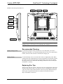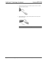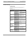
1
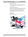
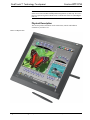
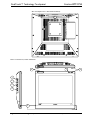
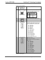
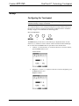
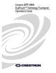
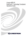
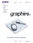
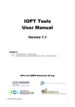
Crestron DTT-17V3
DualTouch™ Technology Touchpanel
Operations Guide
This document was prepared and written by the Technical Documentation department at:
Crestron Electronics, Inc.
15 Volvo Drive
Rockleigh, NJ 07647
1-888-CRESTRON
All brand names, product names and trademarks are the property of their respective owners.
©2007 Crestron Electronics, Inc.
Crestron DTT-17V3
DualTouch™ Technology Touchpanel
Contents
DualTouch™ Technology Touchpanel: DTT-17V3
1
Introduction ............................................................................................................................... 1
Features and Functions ................................................................................................ 1
Applications................................................................................................................. 2
Specifications .............................................................................................................. 3
Physical Description.................................................................................................... 4
Industry Compliance ................................................................................................... 8
Setup .......................................................................................................................................... 9
Configuring the Touchpanel........................................................................................ 9
Supplied Equipment .................................................................................................. 13
Installation ................................................................................................................. 14
Hardware Hookup ..................................................................................................... 16
Recommended Cleaning............................................................................................ 17
Replacing Pen Tips.................................................................................................... 17
Using the Pen........................................................................................................................... 19
Problem Solving ...................................................................................................................... 20
Troubleshooting......................................................................................................... 20
Reference Documents................................................................................................ 21
Further Inquiries ........................................................................................................ 21
Future Updates .......................................................................................................... 21
Return and Warranty Policies .................................................................................................. 22
Merchandise Returns / Repair Service ...................................................................... 22
CRESTRON Limited Warranty................................................................................. 22
Operations Guide – DOC. 6633A
Contents • i
Crestron DTT-17V3
DualTouch™ Technology Touchpanel
DualTouch™ Technology
Touchpanel: DTT-17V3
Introduction
The DTT-17V3 is a 17" touchpanel designed for use with the UPX-2 Universal
Presentation System to support all of the control capabilities of a Crestron
touchpanel, plus pen-based annotation and computer-based multimedia presentation.
Features and Functions
•
•
•
•
•
•
•
•
•
•
User interface for the Crestron UPX-2 Universal Presentation Processor
17" LCD color touchscreen display
1280 x 1024 SXGA resolution
DualTouch Technology - delivers a combination of touchpanel control
and pen-based annotation
Ergonomic Design - allows more natural drawing capability than
ordinary touchpanels
Completely flat bezel for enhanced drawing comfort
Battery-free cordless annotation pen
VGA pass-thru and (2) USB mouse/keyboard ports
Includes tilt stand, pen slot and tether, interface cables, and power
supply
Conforms to VESA 75 mounting standard
DualTouch™ Technology
This Crestron® feature combines fingertip operated touchpanel control with a
precision drawing tablet to produce an amazingly flexible presentation solution.
Crestron DualTouch Technology touchpanels employ a combination of analog
resistive touch sensing for fingertip-operated touchpanel control and Wacom®
Penabled® technology for precise drawing and annotation.
DualTouch Technology allows the presenter to touch the screen with a fingertip to
control AV and lighting functions, and then annotate freely over video and graphic
presentation sources using the wireless pen provided. Switching between modes is
automatic and instantaneous, disabling the analog membrane whenever the pen is
sensed allowing the palm of the hand to be rested naturally on the screen while
drawing.
Operations Guide – DOC. 6633A
DualTouch™ Technology Touchpanel: DTT-17V3 • 1
DualTouch™ Technology Touchpanel
Crestron DTT-17V3
Enhanced Ergonomics
The DTT-17V3 features a completely flat bezel for drawing comfort and reduced
overall size. The adjustable stand allows the touchpanel to be tilted between 17 and
73 degrees. The pressure-sensitive pen is both cordless and battery-free for
performance and reliability.
Versatile Installation Features
The DTT-17V3 ships complete with tilt stand, cables, and power supply. Different
installation options are available using any third-party VESA 75 compliant mounting
solution. An integral security slot enables securing the touchpanel using a
Kensington® compatible security cable (not included). A rear-panel storage slot and
24-inch tether are included to keep the annotation pen at hand. USB ports are
provided on either side of the panel to support the connection of a mouse and
keyboard (not included), and a VGA pass-thru port enables the connection of a
secondary monitor display.
Applications
The following diagram shows a DTT-17V3 in a lecture hall application.
DTT-17V3 in a Lecture Hall Application
2 • DualTouch™ Technology Touchpanel: DTT-17V3
Operations Guide – DOC. 6633A
Crestron DTT-17V3
DualTouch™ Technology Touchpanel
Specifications
Specifications for the DTT-17V3 are listed in the following table.
DTT-17V3 Specifications
SPECIFICATION
DETAILS
Touchscreen Display
Display
Screen Size
Resolution
Color Depth
Contrast Ratio
Brightness
Viewing Angle
TFT active matrix color LCD
17 inch (43.2 cm) diagonal
1280 x 1024 pixels (SXGA)
16.2 million (18 bit + FRC)
500:1
300 nits (cd/m2)
±70 degrees horizontal,
-63 to +67 degrees vertical
Resistive Membrane
Touchscreen
Pen/Tablet
Pen Switches
Side rocker switch; Assigned in UPX-2 Setup
menu; For more information, refer to the
latest version of the UPX-2 Operations Guide
(Doc. 6276) which can be downloaded from
the Crestron website
(www.crestron.com/manuals).
13.30 in x 10.65 in (33.8 cm x 27.1 cm)
508 line per inch (200 lines per cm)
±1 pixel
0.2 in (0.5 cm) maximum
100 points per second maximum
512
Electro-magnetic resonance
LCD Active Area
Resolution
Accuracy
Reading Height
Report Rate
Pressure Levels
Reading Technology
Power Requirements
Touchpanel
External Power Supply
(included)
Enclosure
Construction
40 watts (3.33 Amps) @ 12 Volts DC
100-240 Volts AC, 50-60 Hz
Screen Tilt
Minimum 2-Series Control System
Update File1, 2, 3
Environmental
Temperature
Humidity
Dimensions (including stand)
Height
Width
Depth
Weight
High impact injection-molded case with
adjustable tabletop tilt stand; VESA 75mm
mounting compliant; Kensington security slot
Adjustable 17º to 73º from horizontal
UPX-2-1GB v2.09.00.25
UPX-2-MSO v2.09.00.25
41º to 95ºF (5º to 35ºC).
20% to 80% RH (non-condensing)
13.78 in (34.99 cm) maximum
15.76 in (40.03 cm)
13.85 in (35.18 cm) maximum
13.20 lbs (6.0 kg) – including stand
1. The latest software versions can be obtained from the Crestron website. Refer to the NOTE following
these footnotes.
2. Crestron 2-Series control systems include the AV2 and PRO2. Consult the latest Crestron Product
Catalog for a complete list of 2-Series control systems.
Operations Guide – DOC. 6633A
DualTouch™ Technology Touchpanel: DTT-17V3 • 3
DualTouch™ Technology Touchpanel
Crestron DTT-17V3
NOTE: Crestron software and any files on the website are for authorized Crestron
dealers and Crestron Authorized Independent Programmers (CAIP) only. New users
may be required to register to obtain access to certain areas of the site (including the
FTP site).
Physical Description
This section provides information on the connections, controls and indicators
available on your DTT-17V3.
DTT-17V3 Physical View
4 • DualTouch™ Technology Touchpanel: DTT-17V3
Operations Guide – DOC. 6633A
Crestron DTT-17V3
DualTouch™ Technology Touchpanel
DTT-17V3 Physical View
2.19 in
(5.55 cm)
14.26 in
(36.22 cm)
15.76 in
(40.03 cm)
DTT-17V3 Physical View – Right Side (Maximum and Minimum Height)
13.78 in
(34.99 cm)
13.85 in
(35.18 cm)
5.08 in
(12.91 cm)
8.41 in
(21.37 cm)
Operations Guide – DOC. 6633A
13.40 in
(34.04 cm)
DualTouch™ Technology Touchpanel: DTT-17V3 • 5
DualTouch™ Technology Touchpanel
Crestron DTT-17V3
DTT-17V3 Physical View – Rear (Stand Not Shown)
DTT-17V3 Connectors, Controls & Indicators
6
7
8
1
2
3
4
5
6 • DualTouch™ Technology Touchpanel: DTT-17V3
Operations Guide – DOC. 6633A
Crestron DTT-17V3
DualTouch™ Technology Touchpanel
Connectors, Controls & Indicators
#
CONNECTORS,
CONTROLS &
INDICATORS
USB
1
Pin 1
Pin 2
DESCRIPTION
(1) USB B female; USB 2.0 port;
Pin 4
Pin 3
2
DC IN (12V)
3
ANALOG RGB IN
Connects to any USB port on UPX-2 using
6 ft (2.0 m) USB cable (included)
PIN
DESCRIPTION
1
+5 VDC
2
Data -
3
Data +
4
Ground
(1) DC power jack (power supply included)
(1) DB15HD female; RGB (VGA) video input;
Connects to RGB Output A of UPX-2 using
6 ft (2.0 m) DB15HD VGA cable (included)
Pin 1 Red Video
Pin 2 Green Video
Pin 3 Blue Video
Pin 4 Reserved
Pin 5 Ground
Pin 6 Red Ground
Pin 7 Green Ground
Pin 8 Blue Ground
Pin 9 No Connect
Pin 10 Ground
Pin 11 No Connect
Pin 12 Monitor Sense
Pin 13 Horizontal Sync
Pin 14 Vertical Sync
Pin 15 Monitor Sense Clock
4
ANALOG RGB OUT
(1) DB15HD female;
RGB (VGA) video loop-thru;
Passes RGB input through to an additional
display device
Pin 1 Red Video
Pin 2 Green Video
Pin 3 Blue Video
Pin 4 Reserved
Pin 5 Ground
Pin 6 Red Ground
Pin 7 Green Ground
Pin 8 Blue Ground
Pin 9 No Connect
Pin 10 Ground
Pin 11 No Connect
Pin 12 No Connect
Pin 13 Horizontal Sync
Pin 14 Vertical Sync
Pin 15 No Connect
(Continued on following page)
Operations Guide – DOC. 6633A
DualTouch™ Technology Touchpanel: DTT-17V3 • 7
DualTouch™ Technology Touchpanel
Crestron DTT-17V3
Connectors, Controls & Indicators (Continued)
#
CONNECTORS,
CONTROLS &
INDICATORS
5
USB
MOUSE/KEYBOARD
DESCRIPTION
(2) USB Type A female
USB 2.0 hub ports for mouse/keyboard (not
included)
Device Power: 500 mA maximum per port
6
MENU, -, +, ENTER
(4) Pushbuttons to navigate onscreen setup
menu
7
STATUS LED
(1) Blue LED indicates sensing of annotation
pen
8
POWER BUTTON &
LED
(1) Pushbutton turns unit on/off
(1) Dual-color LED; Blue indicates power is on
with a valid RGB input signal connected; turns
amber when RGB signal is disconnected
Industry Compliance
As of the date of manufacture, the DTT-17V3 has been tested and found to comply
with specifications for CE marking and standards per EMC and
Radiocommunications Compliance Labelling.
NOTE: This device complies with part 17 of the FCC rules. Operation is subject to
the following two conditions: (1) this device may not cause harmful interference and
(2) this device must accept any interference received, including interference that may
cause undesired operation.
This equipment has been tested and found to comply with the limits for a Class B
digital device, pursuant to part 17 of the FCC Rules. These limits are designed to
provide reasonable protection against harmful interference in a residential
installation. This equipment generates, uses and can radiate radio frequency energy
and if not installed and used in accordance with the instructions, may cause harmful
interference to radio communications. However, there is no guarantee that
interference will not occur in a particular installation. If this equipment does cause
harmful interference to radio or television reception, which can be determined by
turning the equipment off and on, the user is encouraged to try to correct the
interference by one or more of the following measures:
Reorient or relocate the receiving antenna.
Increase the separation between the equipment and receiver.
Connect the equipment into an outlet on a circuit different from that to
which the receiver is connected.
Consult the dealer or an experienced radio/TV technician for help.
8 • DualTouch™ Technology Touchpanel: DTT-17V3
Operations Guide – DOC. 6633A
Crestron DTT-17V3
DualTouch™ Technology Touchpanel
Setup
Configuring the Touchpanel
NOTE: The only connection required to configure the touchpanel is power. Refer to
“Hardware Hookup” on page 16 for details.
The touchpanel display can be configured using the four setup buttons on the top of
the DTT-17V3. Power is required to configure the touchpanel. Refer to “Hardware
Hookup” on page 16 for information on connecting power.
Onscreen Setup Buttons
MENU
-
+
ENTER
The Menu button provides access to the following 11 adjustment menus. Use the
Selection (-)/(+) buttons to select a menu or advance forward or backward through
the 11 menus. Press the Enter button to open and save the selected menu.
1.
Contrast – Use the selection (-)/(+) buttons to decrease or increase contrast,
press the Enter button to save.
Contrast Control
2.
Brightness – Use the (-)/(+) buttons to decrease or increase brightness, press
the Enter button to save.
Brightness Control
Operations Guide – DOC. 6633A
DualTouch™ Technology Touchpanel: DTT-17V3 • 9
DualTouch™ Technology Touchpanel
3.
Crestron DTT-17V3
Phase – Use the (-)/(+) buttons to manually reduce horizontal distortion
lines. The Reset option
to save.
is used for automatic adjustment. Press Enter
Phase Control
4.
Pitch – Use the (-)/(+) buttons to manually reduce vertical distortion lines.
The Reset option
save.
is used for automatic adjustment. Press Enter to
Pitch Control
5.
Horizontal Center – Use the (-)/(+) buttons to manually move the image left
or right. The Reset option
Enter to save.
is used for automatic adjustment. Press
Horizontal Center Control
10 • DualTouch™ Technology Touchpanel: DTT-17V3
Operations Guide – DOC. 6633A
Crestron DTT-17V3
DualTouch™ Technology Touchpanel
6.
Vertical Center – Use the (-)/(+) buttons to manually move the image down
or up. The Reset option
to save.
is used for automatic adjustment. Press Enter
Vertical Center Control
7.
Menu Position – Use the (-)/(+) buttons to move the menu to one of the
available nine positions. Press Enter to save. Default is center position.
Menu Position Control
8.
Reset – Use AUTO ADJUST to reset only the image parameters (menus 1
through 6). Use RECALL to reset all screen options to the factory default*.
Select the exit icon to leave this menu without making any changes.
Auto Adjust Control
* Defaults for contrast, brightness, phase, pitch, and center (horizontal and
vertical) depend on the UPX-2’s Display Output settings. For more
information, refer to the latest version of the UPX-2 Operations Guide.
Operations Guide – DOC. 6633A
DualTouch™ Technology Touchpanel: DTT-17V3 • 11
DualTouch™ Technology Touchpanel
9.
Crestron DTT-17V3
Backlight – Use the (-)/(+) buttons to decrease or increase the backlight
brightness. Press Enter to save. Default is 80.
Backlight Control
10. Color – Provides a color temperature selection of 9300K, 6500K, 5000K,
DIRECT (no adjustment to the incoming signal) and a USER option to use
the independent RGB adjustment.
Click the
icon to allow an independent adjustment of red, green and
blue. Press Enter to save. Defaults are shown as follows.
Color Control
RGB Level Control
NOTE: Manual changes invalidate the standard profile settings.
12 • DualTouch™ Technology Touchpanel: DTT-17V3
Operations Guide – DOC. 6633A
Crestron DTT-17V3
DualTouch™ Technology Touchpanel
11. Language – Use the (-)/(+) buttons to select a language for the display
adjustment menus. Press Enter to save. Default is English.
Language Control
Supplied Equipment
The DTT-17V3 is shipped with the following accessories.
Operations Guide – DOC. 6633A
•
(1) Pen (with five tip replacements)
•
(1) USB Cable; Approximately 6-feet long.
•
(1) VGA to VGA Cable; Approximately 6-feet long.
•
(1) Power Supply and Power Cable
DualTouch™ Technology Touchpanel: DTT-17V3 • 13
DualTouch™ Technology Touchpanel
•
Crestron DTT-17V3
(1) Pen Tether
Installation
VESA Mount
The DTT-17V3 may be removed from the adjustable stand and remounted to a
VESA® conforming mount arm or stand. The Video Electronics Standards
Association (VESA) is an international non-profit corporation that supports and sets
industry-wide interface standards for the PC, workstation, and computing
environments. VESA's Flat Display Mounting Interface (FDMI) Standard defines a
set of mounting interface standards for the complete range of flat displays with
viewing areas ranging in size from 102 mm (4") to 2286 mm (90") diagonal. FDMI
supports a broad range of mounting options including desktop, wall, overhead,
mobile and specialty mounting applications. Corresponding standards describe the
interface mounting pads, wall mount brackets and other mounting apparatus to be
provided by mounting equipment manufacturers. The complete standard is available
on the VESA website. The DTT-17V3 is VESA MIS-D, 100/75, C compliant, and is
equipped with a 75 x 75 mm mounting hole pattern.
Follow these instructions for removing the adjustable stand and attaching the
DTT-17V3 to an alternative VESA conforming mount.
1.
Turn off the system and disconnect all cables.
2.
Protect the screen surface by placing the DTT-17V3 facedown on a soft
cloth.
3.
Remove the four screws that secure the stand.
4.
Use four M4 regular screws, no longer than 17 mm, 7 mm wide with a 0.7
mm pitch to attach the new mounting.
NOTE: Screws longer than 15 mm could damage the DTT-17V3.
14 • DualTouch™ Technology Touchpanel: DTT-17V3
Operations Guide – DOC. 6633A
Crestron DTT-17V3
DualTouch™ Technology Touchpanel
VESA Mounting
Rear of DTT-17V3
Alternate Mounting
Platform
M4 Screws
4 mm wide
0.7 mm pitch
15 mm maximum
length
CAUTION: When attaching the DTT-17V3 to an alternate mounting
platform, be sure to follow all instructions supplied by the manufacturer.
Install Pen Tether
The pen can be tethered to the DTT-17V3 using the supplied tether and tether
hardware.
• Loop the tether through the eyelet at one of the two tether locations on the
back of the DTT-17V3 as shown in the following diagram.
Tether Locations
TETHER LOCATIONS
• Loop the tether through the eyelet on the stylus.
Kensington Security Slot
Operations Guide – DOC. 6633A
The Kensington Security Slot is an industry standard that gives customers the best
option for the physical security of computer and electronic equipment. The security
slot is located on the rear of the DTT-17V3 as shown in the Hardware Connections
DualTouch™ Technology Touchpanel: DTT-17V3 • 15
DualTouch™ Technology Touchpanel
Crestron DTT-17V3
diagram on page 17. To prevent unauthorized removal, you can attach one end of a
Kensington security cable to this slot and the other end to an immovable object.
Refer to the Kensington website for additional details (http://www.kensington.com).
Hardware Hookup
Refer to the following diagram and complete the connections as specified. Ensure
that the UPX-2 and the DTT-17V3 are both powered down before beginning.
CAUTION: To avoid damage to the DTT-17V3 or to your video card, never
connect or disconnect the video or power cable while the DTT-17V3 or the UPX-2
are powered up.
NOTE: The USB cable may be extended using up to four 16-foot active extensions.
Each extension cable must contain a hub (repeater) to regenerate the USB signal
(maximum of 64 feet). For longer extensions, Crestron has tested and approved
IOGEAR USB Extender model GUCE50, which allows up to 150 feet over CAT5.
NOTE: Using high quality cable, the VGA cable may be extended up to a
maximum of about 10 meters (32.8 ft.) for analog VGA at 1280 x 1024. If you need
a longer run, add VGA extenders or VGA distribution amplifiers.
1.
Connect the RGB/VGA cable, linking the UPX-2 RGB OUTPUT A
connector to the DTT-17V3 RGB VIDEO IN connector.
2.
Connect the USB cable, linking the UPX-2 USB port to the DTT-17V3
USB port.
3.
Connect the power supply line cord to an AC outlet and the power supply
adaptor.
4.
Plug the power adaptor cord into the DTT-17V3 DC IN port.
5.
Power up the DTT-17V3. The power indicator should light up amber.
6.
Power up the UPX-2. When a video signal is applied to the DTT-17V3, the
power indicator will turn blue.
16 • DualTouch™ Technology Touchpanel: DTT-17V3
Operations Guide – DOC. 6633A
Crestron DTT-17V3
DualTouch™ Technology Touchpanel
Hardware Connections for the DTT-17V3
KENSINGTON
SECURITY
SLOT
PEN HOLDER
VESA MOUNT
USB:
TO UPX-2
DC IN (12V):
FROM POWER
SUPPLY
ANALOG RGB IN:
FROM UPX-2
ANALOG RGB OUT:
TO AUXILIARY
MONITOR
USB ACCESSORY (x2):
TO USB KEYBOARD
OR USB MOUSE
CAUTION: Do not apply excessive pressure to the touchscreen display during
handling. Doing so can crack the screen and damage the touchpanel.
Recommended Cleaning
Display Casing or Pen
To clean the pen display casing or the pen, use a soft, damp cloth; you can also
dampen the cloth using a very mild soap diluted with water. Do not use paint thinner,
benzine, alcohol, or other solvents to clean the unit casing or pen.
Display Screen
To clean the display screen, use an anti-static cloth or a slightly damp cloth. When
cleaning, apply only a light amount of pressure to the display screen and do not make
the surface wet. Do not use detergent to clean the display screen; this may damage
the coating on the screen. Please note that damage of this kind is not covered by the
manufacturer’s warranty.
Replacing Pen Tips
The pen comes with five extra tips. The pen tip will wear with normal use. Worn tips
feel more drag when you draw, or it seems as if you are scratching the overlay with
your pen. It can be easily replaced with one of the extra pen tips. Replacement pens
and a 5-pack of replacement pen nibs are available from the Wacom website
(http://wacomdirect.wacom.com).
Operations Guide – DOC. 6633A
DualTouch™ Technology Touchpanel: DTT-17V3 • 17
DualTouch™ Technology Touchpanel
Crestron DTT-17V3
1.
Grasp the worn tip with a pair of needle-nose pliers, tweezers, or similar
instrument and pull out the tip.
2.
Firmly slide the new tip (square end first) into the barrel of the pen and
press in until it stops.
NOTE: A badly worn pen tip will damage the screen surface.
18 • DualTouch™ Technology Touchpanel: DTT-17V3
Operations Guide – DOC. 6633A
Crestron DTT-17V3
DualTouch™ Technology Touchpanel
Using the Pen
While working with the DTT-17V3, you can rest your hand on the surface of the
display screen, just as if you were drawing on a sheet if paper. The pen is activated
as soon as it enters proximity, about 0.2 inches (5 mm) above the surface. This
allows you to position the screen cursor before touching the pen tip to the surface.
When the pen tip contacts the surface of the DTT-17V3, the tip switch is activated.
The tip switch simulates clicking and holding a mouse button. Raising the tip above
the surface of the DTT-17V3 is the same as releasing a mouse button.
NOTE: Place the pen in the pen holder when not in use.
Operations Guide – DOC. 6633A
DualTouch™ Technology Touchpanel: DTT-17V3 • 19
DualTouch™ Technology Touchpanel
Crestron DTT-17V3
Problem Solving
Troubleshooting
The following table provides corrective action for possible trouble situations. If
further assistance is required, please contact a Crestron customer service
representative.
DTT-17V3 Troubleshooting
TROUBLE
DTT-17V3 does not
function.
POSSIBLE CAUSE(S)
CORRECTIVE ACTION
The DTT-17V3 is not
receiving power (The
Power LED is off).
Verify cable connections and
power to unit.
The DTT-17V3 is
receiving power. (The
Power LED is on.)
Check contrast, brightness and
back-light controls. Refer to
pages 9 and 12.
Multiple images
displayed.
The video cable is overextended.
Use the video cable without
extensions or use a higher
quality cable with VGA
extenders.
White color appears
off-white.
The colors are not set up
correctly.
Return to factory settings or
adjust the colors as necessary.
VGA display ripples
or shows a moiré
pattern.
The pitch and/or phase is
misadjusted.
Adjust pitch and/or phase.
Refer to page 10.
The message: ”NO
SIGNAL GO TO
POWER SAVE” is
displayed.
The system may be in
power management
mode.
Touch the pen tip to the screen,
move the mouse connected to
the UPX-2, or press any key on
the keyboard connected to the
UPX-2.
The video cable
connection may be loose
or broken.
Check the video cable
connection.
The message:
”CABLE
DISCONNECT
GO TO POWER
SAVE” is displayed.
The video cable
connection may be loose
or broken.
Check the video cable
connection.
The message:”OUT
OF RANGE” is
displayed.
Input signal frequency is
incorrect or not
compatible.
Vertical frequency refresh rate
is a value between 45 and 75
Hz (for XGA, vertical refresh
rate is 45 to 70 Hz.
The resolution is set too
high.
Set the resolution to a
maximum of 1280 x 1024.
The refresh rate is set too
high for XGA.
Set the refresh rate for XGA to
a value between 45 and 70 Hz.
The message:
”Please set the
refresh rate at 70Hz
or less” is displayed.
20 • DualTouch™ Technology Touchpanel: DTT-17V3
Operations Guide – DOC. 6633A
Crestron DTT-17V3
DualTouch™ Technology Touchpanel
Reference Documents
The latest version of all documents mentioned within the guide can be obtained from
the Crestron website (http://www.crestron.com/manuals). This link will provide a list
of product manuals arranged in alphabetical order by model number.
List of Related Reference Documents
DOCUMENT TITLE
UPX-2 Universal Presentation Processor
Further Inquiries
If you cannot locate specific information or have questions after reviewing this
guide, please take advantage of Crestron's award winning customer service team by
calling the Crestron corporate headquarters at 1-888-CRESTRON [1-888-273-7876].
For assistance in your local time zone, refer to the Crestron website
(www.crestron.com/offices) for a listing of Crestron worldwide offices.
You can also log onto the online help section of the Crestron website
(www.crestron.com/onlinehelp) to ask questions about Crestron products. First-time
users will need to establish a user account to fully benefit from all available features.
Future Updates
As Crestron improves functions, adds new features and extends the capabilities of
the DTT-17V3, additional information may be made available as manual updates.
These updates are solely electronic and serve as intermediary supplements prior to
the release of a complete technical documentation revision.
Check the Crestron website periodically for manual update availability and its
relevance. Updates are identified as an “Addendum” in the Download column.
Operations Guide – DOC. 6633A
DualTouch™ Technology Touchpanel: DTT-17V3 • 21
DualTouch™ Technology Touchpanel
Crestron DTT-17V3
Return and Warranty Policies
Merchandise Returns / Repair Service
1.
No merchandise may be returned for credit, exchange or service without prior authorization
from CRESTRON. To obtain warranty service for CRESTRON products, contact an
authorized CRESTRON dealer. Only authorized CRESTRON dealers may contact the factory
and request an RMA (Return Merchandise Authorization) number. Enclose a note specifying
the nature of the problem, name and phone number of contact person, RMA number and
return address.
2.
Products may be returned for credit, exchange or service with a CRESTRON Return
Merchandise Authorization (RMA) number. Authorized returns must be shipped freight
prepaid to CRESTRON, 6 Volvo Drive, Rockleigh, N.J. or its authorized subsidiaries, with
RMA number clearly marked on the outside of all cartons. Shipments arriving freight collect
or without an RMA number shall be subject to refusal. CRESTRON reserves the right in its
sole and absolute discretion to charge a 15% restocking fee plus shipping costs on any
products returned with an RMA.
3.
Return freight charges following repair of items under warranty shall be paid by CRESTRON,
shipping by standard ground carrier. In the event repairs are found to be non-warranty, return
freight costs shall be paid by the purchaser.
CRESTRON Limited Warranty
CRESTRON ELECTRONICS, Inc. warrants its products to be free from manufacturing defects in materials
and workmanship under normal use for a period of three (3) years from the date of purchase from
CRESTRON, with the following exceptions: disk drives and any other moving or rotating mechanical
parts, pan/tilt heads and power supplies are covered for a period of one (1) year; touchscreen display and
overlay components are covered for 90 days; batteries and incandescent lamps are not covered.
This warranty extends to products purchased directly from CRESTRON or an authorized CRESTRON
dealer. Purchasers should inquire of the dealer regarding the nature and extent of the dealer's warranty, if
any.
CRESTRON shall not be liable to honor the terms of this warranty if the product has been used in any
application other than that for which it was intended or if it has been subjected to misuse, accidental
damage, modification or improper installation procedures. Furthermore, this warranty does not cover any
product that has had the serial number altered, defaced or removed.
This warranty shall be the sole and exclusive remedy to the original purchaser. In no event shall
CRESTRON be liable for incidental or consequential damages of any kind (property or economic damages
inclusive) arising from the sale or use of this equipment. CRESTRON is not liable for any claim made by a
third party or made by the purchaser for a third party.
CRESTRON shall, at its option, repair or replace any product found defective, without charge for parts or
labor. Repaired or replaced equipment and parts supplied under this warranty shall be covered only by the
unexpired portion of the warranty.
Except as expressly set forth in this warranty, CRESTRON makes no other warranties, expressed or
implied, nor authorizes any other party to offer any warranty, including any implied warranties of
merchantability or fitness for a particular purpose. Any implied warranties that may be imposed by law are
limited to the terms of this limited warranty. This warranty statement supersedes all previous warranties.
Trademark Information
All brand names, product names and trademarks are the sole property of their respective owners. Windows is a registered trademark
of Microsoft Corporation. Windows95/98/Me/XP/Vista and WindowsNT/2000 are trademarks of Microsoft Corporation.
22 • DualTouch™ Technology Touchpanel: DTT-17V3
Operations Guide – DOC. 6633A
Crestron DTT-17V3
DualTouch™ Technology Touchpanel
This page is intentionally left blank.
Operations Guide – DOC. 6633A
DualTouch™ Technology Touchpanel: DTT-17V3 • 23
Crestron Electronics, Inc.
15 Volvo Drive Rockleigh, NJ 07647
Tel: 888.CRESTRON
Fax: 201.767.7576
www.crestron.com
Operations Guide – DOC. 6633A
(2019291)
11.07
Specifications subject to
change without notice.