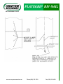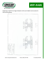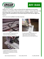
1
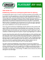
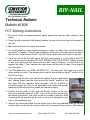
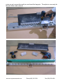
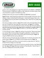
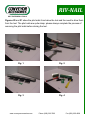
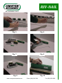
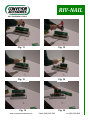
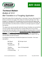
Technical Bulletin Index Page Bulletin # Topic 2 1001 Power Cord Requirements 3–4 1002 Proper Skiving Techniques 5–17 1003 Mechanical Fasteners 18 1004 RNEH-1 Hammer Care 19 1005 RNBH-1 Hammer Care 20 1006 Non-Corrosive Rivet Material 21 1007 Heat Treated Plates Durgard 22–24 1008 FCT Splicing Instructions 25–30 1009 Riv-Nail Fastener Instructions 31–32 1010 Riv-Nail Compression of Fasteners 33–34 1011 Riv-Nail Application Tools 35–37 1012 Belt Transition — Troughing Conveyor Accessories, Inc. 7/22/2014 RIV-NAIL Technical Bulletin Bulletin # 1001 Power Cord Requirements Please be cautious when using power cords to supply the new RNEH-1 electric hammers made by Bosch. The voltage and amps required are 120vac with a 6.5 amp draw. That is about 780 watts. If you are using 2 tools, then the amp requirement is double or about 1600 watts. A 20-amp circuit would be considered minimum. What is considered suitable? Bosch provides a chart in their manual. Although at 150 feet, they say 14 gauge wire is OK, it is best to stay 100 feet or less with a power cord having at least 12 gauge wire. How do I know if I have low voltage? One symptom would be the rivet does not penetrate through the belt and clinch on the back. The rivet tries to drive through, but will start clinching on the inside of the belt. This is not a rivet problem, but a power supply problem. www.conveyoraccessories.com Phone (800) 323-7093 Fax (630) 655-4209 RIV-NAIL Technical Bulletin Bulletin # 1002 Proper Skiving Techniques Belt Type: Heavy Duty Composition: Typically made up of rubber top and bottom covers protecting the carcass or fabric of the belt. In most cases the rubber top side is thicker than the bottom side. Skiving: When preparing heavy duty belting for mechanical belt splicing it has been found that skiving the top of the belt provide two advantages. 1. The belt splice will be stronger. This splice strength has been verified through static pull tests and dynamic running tests under controlled tensile testing. The skived area now allows for a shorter rivet. The shorter the rivet the less moment arm or torque can be applied to the rivet to pull it out. That is why rivet selection is so important. Mechanical belt splices like the RC6 Riv-Nail Splice is a compressive fastener. The top and bottom of the fastener are compressed by the action of the setting of the rivets. Rubber is like a solid fluid mass and can be compressed. It is subject to significant shear force as the carry side of the belt stretches as it goes over pulleys and the underside is placed into compression. It is a proven fact that the top side of a belt 1’ thick going over a 60” head pulley with a 180°wrap will be stretched 1 ½” longer as the underside of the belt is compressed. That is a lot of shear force in motion! 2. Skiving also allows the fastener to sit lower in the belt, allowing the cleaners to pass easier over the belt splice. www.conveyoraccessories.com Phone (800) 323-7093 Fax (630) 655-4209 RIV-NAIL Note: when skiving, always allow at least 1/32” to 1/16” of rubber over the fabric. This will help protect the fabric from being cut by the belt fastener. Finally, always measure the skived section of the belt end when selecting the rivet size. If the skive is more or less uniform, use the longest rivet size for the skived area. CAI anvil plates will allow the excess to flow out and become fully set. If the skive has low and high places, try to use the correct rivet in each area of the skived portion of the belt. www.conveyoraccessories.com Phone (800) 323-7093 Fax (630) 655-4209 PLATEGRIP RIV-NAIL Technical Bulletin Bulletin # 1003 Mechanical Fasteners The following information has been provided by: NIBA-The Belting Association Mechanical fasteners offer an economical, reliable and long lasting belt splice method. They are the most common belt splicing method in use today, for both light and heavy duty conveyor belt applications. Mechanical belt fasteners are easily installed with only a modest amount of mechanical skills and tools. The purpose of this section of the NIBA ENGINEERING HANDBOOK is intended to acquaint the reader with some of the mechanical fasteners available today. The information contained herein is intentionally general in nature. It is recommended that the fastener manufacturers be consulted for specific product and application information and recommendations. The majority of belts being manufactured today are made of synthetic materials which lend themselves to mechanical attachment and most modern conveyor belts are designed for use with mechanical fasteners. This coupled with constantly improving designs and materials in mechanical belt fasteners provide belt operators with a reliable, long-lasting and quite inexpensive way to splice belts. The combination of belts designed for mechanical fastener splices and improved fastener designs has extended the use of mechanical fastener splices to service at higher tensions, and this trend will continue with further fastener and belt developments. Mechanical fastener splices today offer a permanence once considered not available with them. This is due to the combination of fasteners designed and made with improved materials and modern belts that are designed for fastener splices. It also is due to other features designed for fastener splices such as countersinking which www.conveyoraccessories.com Phone (800) 323-7093 Fax (630) 655-4209 PLATEGRIP RIV-NAIL permits maintaining the belt profiles. All belt fastener processes, fastener installation, countersinking, etc. are designed for short notice rather than waiting for outside contractors. This translates into significant cost savings as downtime is minimized and production may continue without substantial interruption. In summary, some of the benefits of using mechanical fasteners are: Cost — Typically, mechanical fasteners offer the lowest cost approach to belt splicing. This is due to lower splice material cost for the mechanical fastener splice components and the fact that the work can be done in-house. Speed of Installation — Typical splices can be installed in minutes, reducing downtime. Ease of Installation — Splicing requires relatively simple and inexpensive tooling which is readily available and can usually be kept on site. While some mechanical skill is needed, it is relatively simple to splice with mechanical fasteners. Safe to Use — There is little or no exposure to chemicals, sharp instruments or heat when installing mechanical fasteners. Ease of Inspection — Splices are visible and give signs of impending failure. Little Extra Belt Length Required — The only belting cut off and discarded is that generated in squaring the belt ends when making mechanical fastener belt splices. The extra length of belt required for mechanical fastener splices is measured in inches. No Shelf Life Limitation — Mechanical fastener splice materials do not deteriorate while in storage. Mechanical fasteners are in use today in many applications involving conveyor belts. Some specific applications where belt fasteners are used include coal mining, hardrock mining, including quarrying and sand and gravel facilities, package handling and distribution centers, as well as agricultural harvesting and food processing. www.conveyoraccessories.com Phone (800) 323-7093 Fax (630) 655-4209 PLATEGRIP RIV-NAIL Types of Mechanical Fasteners Mechanical conveyor belt fasteners are manufactured in two styles, solid plate and hinged. Each has its particular advantages and the selection of fasteners should begin with this basic understanding. Solid plate fasteners span opposing belt ends that have been butted together, forming a tight, sift-free splice. Hinged belt fasteners are applied as individual segments to each belt end and then brought together and connected by means of a connecting hinge pin. Solid plate fasteners are generally employed where a sift-free splice is required, such as bulk conveying applications. The two belt ends, having been brought firmly together, prevent fines from sifting through the splice area. Generally, solid plate fasteners are considered as a permanent attachment and are seldom used where the belt or the conveyor must be frequently taken apart. For the most part, solid plate fasteners require larger minimum pulley diameters than hinged fasteners. Hinged fasteners, as implied above, can be operated on systems employing smaller pulley diameters. This inherent design feature allows for a broader range of applications than is available with corresponding solid plate fastener styles. Hinged fastener splices can be separated for belt removal or maintenance by removing the hinge pins. Some hinged fasteners have a sift preventing component and thus can be used on belts conveying fines, but they are more frequently applied in other applications. As the "working" part of a hinged fastener splice, the hinge pin should be selected as carefully as the fastener itself. Quite often it makes sense to select a pin of the same material as the fastener. For example, a stainless steel pin would be chosen for a stainless steel fastener. Solid (single) wire pins are the easiest to insert and are most often used on non-troughing applications. Stranded cable wire pins are recommended for troughing conveyors given their greater flexibility. Both solid wire pins and stranded cable pins are offered either with or without an external polymer covering. This polymer "jacket" serves as a lubricant when positioned between the loops of the hinged fasteners. As such, this pin style is less www.conveyoraccessories.com Phone (800) 323-7093 Fax (630) 655-4209 PLATEGRIP RIV-NAIL likely to wear or corrode. However, they are not the preferred choice where fine abrasive materials are being conveyed, wherein a solid wire or unjacketed cable pin is a better selection. Other hinge pin choices include nonmetallic pins for smooth running at lower belt operating tensions as well as notched or corrugated pins which reduce the likelihood of pin migration. Hinge pin selection is as important as proper hinged fastener selection. Properly selected and installed, they contribute to maximum splice life and performance. As with selecting hinged fasteners, the fastener manufacturers should be consulted for hinge pin recommendations. The market for conveyor belt fasteners generally breaks down into two major segments, light duty and heavy duty. NIBA designates light duty belts as those having a tension rating of 160 PIW or less, and heavy duty belts as those with tension ratings over 160 PIW. Light duty conveyor belt fasteners include wire hooks, common bar lacing, stapled plate fasteners, plastic hinged plate fasteners and plastic spiral loop fasteners. Heavy duty conveyor belt fasteners include bolted and riveted plate fasteners and stapled, bolted and riveted hinge fasteners. Heavy duty fasteners are available for operating tensions up to 1500 PIW. While it is suggested that the individual manufacturer’s fastener catalogs be consulted for application information, a representative sampling of fastener types is illustrated in the following pages for reference. Notable Features: Bolted Hinge Heavy duty bolt hinge fastener for bulk haulage applications. Commonly used in low to medium tension industrial belts requiring a hinged splice. The fastener plates are compressed into the belt by special bolts and nuts. Only simple hand tools needed for installation. www.conveyoraccessories.com Phone (800) 323-7093 Fax (630) 655-4209 PLATEGRIP RIV-NAIL Riveted Hinge Plate Heavy duty riveted hinge fastener for medium to high tension bulk haulage applications. Available in several types of rivets and fasteners. Special rivets are driven through the belts, without pre-punching holes, to compress the fastener plates into the belt. Heavy Stapled Plate Heavy duty stapled hinged fastener for medium to high tension bulk haulage applications. High strength staples are driven through the belts without pre-punching holes, to compress the fastener plates into the belt. Provides a very flexible splice. Bolted Solid Plate Solid plate butt joint compression belt splice. Like the bolt hinge, special bolts and nuts are used to compress the plates into the belt surfaces. These fasteners are generally used for the heavier bulk haulage applications where a sift-free, more permanent belt installation is needed. Only simple hand tools needed for installation. Riveted Solid Plate Solid plate butt joint compression belt splice for medium to high tension bulk haulage applications. Special rivets are driven through the belts without pre-punching holes. These fasteners are generally used for applications where a sift-free, more permanent belt installation is needed. Mechanical Fastener Selection Mechanical fasteners for belting are to be selected in much the same process as belting. To properly select a mechanical belt fastener both the physical and environmental factors must be considered, but not to be forgotten are the experience factors. Many belting manufacturers provide a recommended belt fastener style based on working tension, pulley size and construction of the belting. Mechanical belt www.conveyoraccessories.com Phone (800) 323-7093 Fax (630) 655-4209 PLATEGRIP RIV-NAIL fastener manufacturers provide tables which are to be used as a guideline based on belt thickness and pulley diameters. While the user/installer should refer to the belting and fastener selection guides, the decision process must then include product based on type of service desired (Hinged - Solid Plate), type of material (Carbon Steel - Stainless Steel - Plastic - Other), installation techniques (Hand or Power Tools, or Specialized Machines). The technical manual has provided a description of the various types of mechanical fasteners, the notable features and a chart entitled Fastener Selection which summarizes the range of specifications they may fit. In addition, a Fastener Materials chart is shown that illustrates the "normal use" of each material. Description of Metals Mild Carbon Steel General service where corrosion, sparking or magnetic attraction is not a consideration, sometimes plated to prevent rusting. High Carbon Steel Same as above, except for improved tensile strength and abrasion resistance. Hardened Alloy Steel Highly abrasion resistant, providing several times service life of regular steel in highly abrasive situations. Not recommended for corrosive environments. Stainless Steel 400 Series Provides some corrosion and chemical resistance when compared with carbon steel; is magnetic and can be used with magnetic tramp removal devices. www.conveyoraccessories.com Phone (800) 323-7093 Fax (630) 655-4209 PLATEGRIP RIV-NAIL 300 Series Non-rusting and provides extra resistance to corrosion from acids and chemicals; excellent where sanitation requirements are high; basically non-magnetic. Others Ask your fastener manufacturer for other special materials, metallic and non-metallic, for operating environments. Mechanical Fastener Installation Recommendations Whenever a mechanical fastener is installed, the steps required (which could include pulling slack, squaring, cutting, skiving, lacing, installing hinge pin, etc.) can be made easy and safe by the use of proper tools and procedures. It is recommended that you contact a NIBA member with the specifics of your application. They can make an appropriate recommendation regarding the products and techniques available to meet your need. Squaring Belt Ends Having carefully selected the best fastener style suited to the application, properly installing these fasteners will greatly improve the splice service life. The first step towards ensuring that the fasteners and belt will work effectively in tandem with each other, and the supporting framework, is to install the fasteners square to the belt centerline. With any mechanical splice, the most common installation error is not applying the splice straight. Although there are many suggested methods of accomplishing this, placing a carpenter's square along an average centerline of the belt (taken at several points along its length) is the simplest. Using the belt edge as a squaring guide is not generally recommended. Preparation of the belt ends is important and operators should be sure they have the right tools for doing the job properly. These include cutters, pull-up clamps and any special equipment for recessing fasteners in the belt www.conveyoraccessories.com Phone (800) 323-7093 Fax (630) 655-4209 PLATEGRIP RIV-NAIL cover. This procedure is generally helpful to extend fastener life and avoid operating problems. Splice life may also be prolonged through a good program of preventive maintenance, including periodic inspection and, where necessary, replacement of worn splice sections or entire splices.(Refer to Tech Note #14 Establishing Centerlines and Squaring Belt Ends for Splicing noted on last two pages of bulletin.) Counterskiving / Skiving While mechanical conveyor belt fasteners can be readily applied directly to the belt covers, there are some instances where it is advantageous to lower the fasteners into the belt. Countersinking the fasteners lowers the overall profile of the splice and is most frequently done on the carrying side of the belt. Depending on the belt construction, fasteners may also be countersunk into the bottom covers. When fasteners have been countersunk, less material is left exposed to contact with the contents being conveyed, scrapers, plows, idlers and other related conveyor hardware. Wear through abrasion is greatly minimized thereby extending splice service life. Under running conditions there is also less abusive impact wear to both the splice and the belt. Countersinking is equally suited to light or heavy-duty belts, although generally there are subtly different reasons for choosing to install belt fasteners in this fashion. In the greater number of instances, light-duty belts are more apt to be suspended on slider beds. In these cases, countersinking will reduce abrasive wear of both the fastener and the slider bed. "Hidden" splices are a form of countersunk fastener. After the belt ends have been prepared and the fasteners installed, replacement cover stock is laid over the fasteners and cured. This replacement cover stock may be from such materials as two component systems or uncured rubber stock. The replacement top cover that hides the splice also serves to protect the fasteners from impact and abrasive wear. Preparing a belt for countersinking is readily accomplished using only some additional portable tooling. The options range from small hand held tools to larger, more www.conveyoraccessories.com Phone (800) 323-7093 Fax (630) 655-4209 PLATEGRIP RIV-NAIL mechanical, devices. All are designed for field use by company personnel. The fastener manufacturers offer these tools, and should be consulted for information relating to them. Belt Notching In hinge fastener splices, it is often important to notch or chamfer the corners of the belt ends in the splice, usually at an approximate 60º angle. This will help prevent hang-up of the belt corners on conveyor structure should such contact arise. In onedirectional belts, it is only necessary to notch the trailing belt end. Mechanical Fastener Troubleshooting Guide Problem Solution Code Fastener "comb-out" through end of belt without opening 6,2,3,4,5 Fasteners open up and release from belt 2,1,3,7 Belt breaks behind fastener 2,4,6 Splice failing at edges 3,1,5 Fastener parts fracture and fail 5,3,2,4,7 Belt fails under splice 6,3,1 Fastener wears out prematurely 7,8 Solution Codes 1=Improper fastener installation, including splice not in squarely. www.conveyoraccessories.com Phone (800) 323-7093 Fax (630) 655-4209 PLATEGRIP RIV-NAIL 2=Improper fastener selection, particularly in the choice of too large a fastener. 3=Tension excessive and/or counterweight excessive. 4=Pulley problems, worn lagging, dual pulley speed differential, too small pulleys, material buildup on pulleys. 5=Splice "hang-up" on worn idlers or other parts of the conveyor. 6=Conveyor drive under belted. 7=Improper metal selection. 8=Failure to recess splice Most Common Types of Failure Associated With Mechanical Fasteners Tensile failure of belt. (Warp yarns fracture with fasteners intact.) Tensile failure of fasteners. (Fasteners open or break with belt intact.) "Comb through" tensile failure of belt. (Fill yarns comb out of end of belt with warp yarns and fasteners left intact.) Fatigue/wear failure of belt. (Used belt fractures warps and ruptures behind fasteners. Differentiated from tensile failure of belt by fact that failure occurs only after extended running time.) Fatigue/wear failure of fasteners. (Fasteners break or open up after extended running time.) Wrong size fastener selected. User tries to standardize one size for all belts. "Bigger is better" mentality. User has failure, so he goes to next size bigger fastener for more strength. www.conveyoraccessories.com Phone (800) 323-7093 Fax (630) 655-4209 PLATEGRIP RIV-NAIL Fastener Selection Chart Bolted Hinge Riveted Hinge Plate Heavy Stapled Hinge Plate Bolted Solid Plate Riveted Solid Plate Recommended Minimum Pulley Diameter for 6” or 150mm 9” or 225mm 6” or 150mm 12” or 300mm 18” or 450mm 7/32” –11/16” 3/16” – 7/8” 3/16” – 1-3/16” 7/32” – 15/16” Smallest Size Belt Thickness Range (after countersinking, if used) ¼” – 7/8” or or 5.6mm – 4.8mm – 17.5mm 22.2mm Steel Steel Stainless Stainless or or 4.8mm – 30.2mm 5.6mm – 23.8mm Steel Steel Steel Stainless Stainless Stainless Bronze Bronze Alloy steel wear plates Alloy steel wear plates Nickel Alloy 6.4mm 22.2mm Materials Offered or Alloy steel wear plates Maximum Belt Rating Contact Contact Contact Contact Contact Fastener Fastener Fastener Fastener Fastener Mfg. Mfg. Mfg. Mfg. Mfg. www.conveyoraccessories.com Phone (800) 323-7093 Fax (630) 655-4209 PLATEGRIP RIV-NAIL TECH NOTE #14 Establishing Centerlines and Squaring Belt Ends For Splicing Crooked flat belt splices cause a number of operational problems that probably could be avoided if accurate centerlines or square lines had been established when the splices were made. All flat belt splicing requires careful establishment of reference or cut lines that ensure that the belt alignment will be straight through the splices. In vulcanized splices, this applies to a number of lines on both belt ends, all of which are referenced to a centerline or transverse line that is truly accurate. In mechanical fastener splices, this applies to the transverse cut line on the two ends to be joined. There are some mechanical fastener splices that are made at an angle, and these also require establishment of an accurate transverse line. There are several methods for establishing accurate reference and cut lines in belt splices. NIBA recommends the method illustrated on the next page. This involves measuring across the belt width on both belt ends at five points spaced one to two feet apart, starting from the belt ends, and marking the center at each point. Then, a centerline is marked through the five points, using a long straightedge or a chalk line. In most cases, the center marks will not be perfectly aligned, so the centerline mark will have to be that line that lies closest to the most center marks. Having marked the two centerlines, mark a transverse line at the desired location on each belt end by laying one leg of a carpenters square along the centerline, and a straightedge along the transverse leg of the carpenters square, and apply a mark across the belt. This will be the cut line for mechanical fastener splices, and the reference line for laying out the cut and other reference lines for vulcanized splices. The other methods of establishing cut and reference lines are the centerline arc method, squaring off the existing belt edges method, and the triangulation method. All of these methods are either more complex than the NIBA recommended method, or they depend on straight, undamaged belt edges, a condition that probably exists in new belting, but rarely does in used belting. The NIBA method minimizes the effect of damaged or worn belt edges. www.conveyoraccessories.com Phone (800) 323-7093 Fax (630) 655-4209 PLATEGRIP RIV-NAIL www.conveyoraccessories.com Phone (800) 323-7093 Fax (630) 655-4209 RIV-NAIL Technical Bulletin Bulletin # 1004 Riv-Nail RNEH-1 Hammer Care Please refer to the Bosch Operating / Safety Instructions for Model 11320VS. The only modification to this product is the trigger lock. It has been disabled to meet code. Follow all safety instructions and use PPE as required by your firm and or regulatory guidelines. This is a tool designed for demolition, thus it is quite powerful. Inspection of the tool and the components should be conducted each shift. Installing the SDS+ Drive Punch requires that the shank end be cleaned and greased with a light grease before each use. Follow the guidelines on page 7 of the manual to install or remove the tool from the Hammer. The service interval is approximately 800 hours. Contact your local CAI distributor or call Bosch directly for service. After belt splicing, always inspect your tools for wear or fatigue. Take appropriate action so your tools will be ready and available for the next belt splicing job. If extension cords are required, follow the National Electrical code for guidelines. A sample table is found on page 14. Remove the SDS+ Drive Punch prior to storage. Pull and hold locking sleeve backward, then pull the Drive Punch forward. Wipe clean after removal so dirt will not adhere to the grease. Always clean your tools before storing them in the case provided. www.conveyoraccessories.com Phone (800) 323-7093 Fax (630) 655-4209 RIV-NAIL Technical Bulletin Bulletin # 1005 Riv-Nail RNBH-1 Hammer Care Please refer to the Bosch Operating / Safety Instructions for Model 11536VSR. Follow all safety instructions and use PPE as required by your firm and or regulatory guidelines. This is a tool designed for demolition, thus it is quite powerful. Inspection of the tool and the components should be conducted each shift. Use in hammering mode only. (See page 10) Installing the SDS+ Drive Punch requires that the shank end be cleaned and greased with a light grease before each use. Follow the guidelines on page 9 of the manual to install or remove the tool from the Hammer. The service interval is approximately 800 hours. Contact your local CAI distributor or call Bosch directly for service. After belt splicing, always inspect your tools for wear or fatigue. Take appropriate action so your tools will be ready and available for the next belt splicing job. Follow the instructions on pages 11–12 when charging the battery pack. If extension cords are required, follow the National Electrical code for guidelines. A sample table is found on page 14. Remove the SDS+ Drive Punch prior to storage. Pull and hold locking sleeve backward, then pull the Drive Punch forward. Wipe clean after removal so dirt will not adhere to the grease. Always clean your tools before storing them in the case provided. www.conveyoraccessories.com Phone (800) 323-7093 Fax (630) 655-4209 RIV-NAIL Technical Bulletin Bulletin # 1006 Non-Corrosive (430SS) Rivet Material Advantages In order to attain the longest splice wear life in highly corrosive applications, the use of stainless splices should always be used in conjunction with stainless rivets. The wall thickness of a rivet is about 1/32” thick and the RC6 fastener is about 7/64” thick. In comparison, the fastener is 3.5 times thicker than the rivet. Given these factors, a carbon steel rivet would corrode in 20–25% of the time it takes to corrode a steel fastener strip. The end result: The acid will attack the rivet causing the rivet to fail If used, the high quality CAI stainless alloy fastener strip would not be affected The belt will pull apart due to corroding rivets With regard to the rivets, Conveyor Accessories, Inc. uses 430 stainless steel composed of 50% more carbon and chrome content. The use of this material composition produces: A higher yield of strength when compared to 409SS Considerable corrosion resistance to mine acid water The benefits: Longer splice wear life Less downtime Reduced maintenance intervals www.conveyoraccessories.com Phone (800) 323-7093 Fax (630) 655-4209 PLATEGRIP Technical Bulletin Bulletin # 1007 Heat Treated Plates Durgard Durgard is a special heat-treated steel with abrasion resistant characteristics that provides several times the life of standard steel. Durgard Plategrip fasteners are not recommended for use in corrosive environments, but are specially designed for abrasive situations. Durgard fasteners are heat treated to file hard — “Rockwell C 60 Plus” surface to provide longer service life through improved abrasion resistance. Hardness:* Color: Available: Sizes: Rockwell C 60+ Black Mottled Tops only or Top & Bottom Plates 1, 140, 190, 1–1/2, 1–1/4, 2–1/2, 3 Heat Treated Plates Cross Reference CAI-DURGARD NOMENCLATURE DESCRIPTION COMPETITOR NOMENCLATURE EDT 25 Set/BX — Heat Treated Tops Remainder Steel EMA CDT 100 Set/BX — Heat Treated Tops Remainder Steel CMA ED 25 Set/BX — Heat Treated Top & Bottom Plates EMAP CD 100 Set/BX — Heat Treated Top & Bottom Plates CMAP *Competitive parts are Rockwell C 35 (Approx.) www.conveyoraccessories.com Phone (800) 323-7093 Fax (630) 655-4209 RIV-NAIL Technical Bulletin Bulletin #1008 FCT Splicing Instructions 1. Be sure to wear the proper personal safety equipment required when making a belt splice. 2. Once the belt is spotted in the desired location, be sure to lock and tag out the power to the unit. 3. Mark and cut the belt as square as possible. 4. For visual reference, using a belt marking pen, crayon, or chalk, mark on the belt where the Kevlar® is located. This will help orientation of the belt on the application tool later in the process. Note that the Kevlar® may NOT be located in the exact center of the belt. 5. Take one half of the CAI belt splice, RC-6-42, and position it on one side of the FCT belt, making sure it is centered. DO NOT SPREAD THE CLIPS APART. Rather, starting at one end, gently tap the splice onto the belt using a hammer, until the belt is up against the stops. Then, hammer the clips down onto the belt to keep it from slipping out of the clips. 6. The CAI application tool, RNAT-48-MDA1-FCT, has two rods. The larger pin is used when setting the rivets. The smaller pin is used for pre-drilling the Kevlar® section of the belt for the rivets. 7. After removing the two rods, position the splice onto the application tool, making certain that the clips around the Kevlar® section of the belt align with the template holes beneath. Use the R-STOP to correctly position the belt on the application tool. Insert the smaller diameter rod back through the guides and the splice loops. R-STOP 8. Position the drill guide, R-DG, over the Kevlar® section of the belt. Using the specially made bit, R-BIT, drill a hole into the belt through the twenty guide holes. The collar on the bit is made to stop just short of passing all the way through the belt, so as to not damage the rivet sets on the application tool. 9. After all the holes are drilled, set the center rivet in the two predrilled holes on the two outside clips over the Kevlar® section of the belt to prevent it from moving. When those www.conveyoraccessories.com Phone (800) 323-7093 Fax (630) 655-4209 rivets are set, remove the small pin, and insert the large pin. The splice is now ready for the rest of the rivets to be set. www.conveyoraccessories.com Phone (800) 323-7093 Fax (630) 655-4209 www.conveyoraccessories.com Phone (800) 323-7093 Fax (630) 655-4209 RIV-NAIL Technical Bulletin Bulletin # 1009 Installation Instructions Riv-Nail Belt Fasteners CAI Riv-Nail fasteners can be installed on conveyor belt using several methods. The most basic method is the “Single Driving” method using a RNAT (Riv-Nail Application Tool), see figure 1. The belt ends are prepared; the belt thickness is then gauged to determine the appropriate rivet size. See figure 2. Always use a rivet long enough to go through the belt, never use a rivet that may be too short. In figure 3, samples of R2, R3, TR4 and R5 are shown. The “U” shaped rod in the center of the table is used to lift the Gauge Rod Guides if there is a need to change from the basic R5 setting to the R5 ½ or R6. A rapid install option is available as shown in figure 4. There is a 1kg hammer, a 2 kg sledge hammer, the belt gauge to select rivet sizes, a single driver punch and a 5prong multi driver punch. These are used in conjunction with a RN500, 20 rivet block or a RN500DW that will hold 40 rivets. In addition to the selection of hammers and drivers, 2 sizes of gauge rods are available. The basic 6.4 mm rod can be used on fasteners from R2 through R6 by setting the RN24 and RN25 to the proper selection as engraved on the anvil plates. See figure 5. When looking at figure 6 note the gauge rod is much larger and used exclusively with R5 ½ and R6. The advantage of the larger gauge rod is to help control the loop of the fastener and to make it easier to install the hinge pins for thicker belts. When using this option, a gauge rod of 11 mm is used along with the RN716 gauge rod guide. These are shown in figure 6. The basic requirement of the tooling is again shown in figure 7. This time you see the application tool that has a wider platform compared to the single driver tool. The www.conveyoraccessories.com Phone (800) 323-7093 Fax (630) 655-4209 RIV-NAIL purpose of the wider platform is to support the guide pins of the RN500 or RN500DW. These are blocks of UHMW with a captive o-ring to keep the rivet blocks stable. Note, use some light oil or grease to lubricate the o-rings. All Rapid Install Tools can use both the RN500 and RN500DW rivet blocks. Figure 8 shows using the gauge rod guide lifter to set the guides to the proper size of fasteners. Always double check this setting prior to placing the fastener strip on the tool. Figure 9 shows the belt fastener and belting in place, before the rivet guide block is set in place. The rivets are loaded, as shown in figure 10. Load all rivets in the block before driving the rivets. A single driver may seem like a slow process, see figure 11, but lighter hammers can be used just as effectively as heavy hammers. By working the fastener and rivets from the loop to the outer edge, the job is completed in one pass. Figure 11 shows a .5 kg hammer whereas figure 12 shows a 1.0 kg hammer. Both yield excellent results. A 2.2 kg hammer is shown, in figure 13, driving a 5 prong driver. Strong heavy blows are required. After all rivets are driven through the guide block, the rivets must be hammered several more times to fully set the rivets into the belt splice. Figure 14 shows the RN500 with the 5 prong multi-driver. After the rivets are driven through the rivet guide block, the block is removed from the tool as shown in figure 15. The RN500 is shown being removed in figure 16. Figure 17 illustrates a multi-driver tool can be used as a single driver tool. Note the Riv-Nail is driven straight, not at an angle. The finished belt splice is removed from the tool by pulling the gauge rod and lifting the belt. See figure 18. Figure 19 shows the bottom of the belt splice. Note the flare of the rivets, indicating the rivets are fully clinched. www.conveyoraccessories.com Phone (800) 323-7093 Fax (630) 655-4209 RIV-NAIL Figures 20 and 21 show the pilot nails from below the tool and the need to drive them from the tool. The pilot nails are quite sharp; please always complete the process of removing the pilot nails before storing the tool. Fig. 1 Fig. 2 Fig. 3 Fig. 4 www.conveyoraccessories.com Phone (800) 323-7093 Fax (630) 655-4209 RIV-NAIL Fig. 5 Fig. 6 Fig. 7 Fig. 8 Fig. 10 Fig. 9 www.conveyoraccessories.com Phone (800) 323-7093 Fax (630) 655-4209 RIV-NAIL Fig. 11 Fig. 12 Fig. 13 Fig. 14 Fig. 16 Fig. 15 www.conveyoraccessories.com Phone (800) 323-7093 Fax (630) 655-4209 RIV-NAIL Fig. 17 Fig. 18 Fig. 19 Fig. 20 Fig. 21 www.conveyoraccessories.com Phone (800) 323-7093 Fax (630) 655-4209 RIV-NAIL Technical Bulletin Bulletin # 1010 Riv-Nail Compression of Fasteners The comparative advantage of the CAI design yields superior compression of fastener strips on conveyor belt. As a practical matter, conveyor belt thickness varies in thickness in both length and width of the belt. A new belt may have a variance as small as 1/32”; however, belt in service may have differences as great as 1/8”. A rivet and installation systems to install rivets must accommodate such large variances, yet compress and maintain compression of the fastener on the belt throughout the service life. CAI recognized this need when designing the tooling to build the fastener strips, rivets and pilot nails used when splicing conveyor belts. A unique installation system was designed and patented (US Patent 5,680,790 date October 28, 1997) to assist in yielding the strongest possible fastener holding ability. Drawings included with this bulletin illustrate cross sectional views of the CAI splice and a competitive product. The upper plate design is coined to a depth to allow the rivet head to sit with the dome of the head just above the surface of the upper side of the plate. Every rivet will be struck on the dome of the head to concentrate the driving force through the central axis of the rivet and pilot nail. The leading edge of the fastener and the rivet coin are pulled into the top cover of the belting. The lower plate has a deeper coin to allow more space for the rivet to form and retain the fastener. The lower coining punch strikes the strip .015 deeper, yielding a deeper, under cavity for the rivet to flow as it is set. A side benefit is that the aperture creates a funnel shape hole to help the pilot nail and rivet to enter during initial driving. The second benefit is that because the vortex is slightly larger than the upper plate hole, the rivet can enter the cavity prior to www.conveyoraccessories.com Phone (800) 323-7093 Fax (630) 655-4209 RIV-NAIL beginning to swell into a larger diameter as the semi tubular rivet receives its final clinching blows. www.conveyoraccessories.com Phone (800) 323-7093 Fax (630) 655-4209 RIV-NAIL Technical Bulletin Bulletin # 1011 Riv-Nail Application Tools The June 2008 catalog, GP2008, dedicated 8 pages to Riv-Nail tools and accessories to install Riv-Nail fasteners. CAI innovations include: 1993 — First air powered tool 1993 — First collated rivets 1995 — First improved anvil to set rivets 1995 — First aluminum light weight tool 2005 — First electric driver system 2006 — First battery driver system 2007 — First aluminum Skiver/Cutter Recently, a competitor has introduced their first ever aluminum rivet installation tool, one that weighs 48% more than our tool. I believe they will be promoting this tool, not because of its weight advantage over steel, but because they designed a feature to “nest” with the scalloped edge of their fastener. The design could be a detriment to the fastener as the scalloped tab on the tool can become distorted and prevent the scalloped edge of their fastener from fitting with the tool correctly. Perhaps part of the intent was also to keep the superior edge design of CAI fasteners from fitting the tool. Modifications require only a few minutes. As part of the aluminum base, a machined tab of the base is designed to allow the competitive fastener strip to nest. See Fig. 1. www.conveyoraccessories.com Phone (800) 323-7093 Fax (630) 655-4209 RIV-NAIL Observe Fig. 2 and Fig. 3, and you will see that the machined tab can be easily modified or removed with a chisel, a flat punch or a grinder. If using a flat punch, strike the machined tab on an angle and the aluminum will readily conform. If using a grinder, grind the machined tab so the beveled edge will match with the edge of the fastener. A 60” tool can be modified in less than 5 minutes. Fig. 1 Fig. 2 Close-in view illustrates a machined tab directly in front of the center rivet setting hole to conform to the scalloped edge of the fastener. This photo illustrates a technique that can be used to create an angle or bevel on the machined tab. Two to four strikes may be required to bevel the tab so the fastener will lay flat on the tool. Fig. 3 A simple angle grinder is shown grinding an angle/bevel on the machined tab. A fast and easy technique to modify the tab for use with all rivet fasteners. www.conveyoraccessories.com Phone (800) 323-7093 Fax (630) 655-4209 RIV-NAIL Technical Bulletin Bulletin # 1012 Belt Transition in a Troughing Application Most bulk haulage utilizes troughing idlers to carry loads. Conveyor idlers support the belt as it conforms to the angle of the outside rolls. When the belt goes from “flat to troughed” or “troughed to flat”, the geometric line of travel of the outer edges of the belt exceeds the central line of travel. As edge tensions of the belt are increased, the belt and belt fabric must either stretch or travel at a much higher speed to complete the transition. This edge tension can be kept within safe limits if proper transitions are used with the conveyor systems. Both manufacturers of conveyor belting and conveyor idlers recommend and provide data to follow when designing conveying systems. Included in that data are recommendations for Terminal Pulley Locations, Minimum Transition Distances, and Locations of Transition Idler Arrangements. While the data and recommendations are provided, seldom are the reasons given to explain “why” the recommendation should be followed. An example is the best way to illustrate the dynamics of a transition. First some assumptions: Belt Speed 800 feet per minute Belt Width 60” Troughing Idler 35° Transition None, Full trough depth Distance Idler to Terminal Pulley 5’ www.conveyoraccessories.com Phone (800) 323-7093 Fax (630) 655-4209 RIV-NAIL Under these conditions the center of the belt will travel at the rate of 800 feet/minute and the two outer edges will travel at the average rate of 968 feet/minute in the transition. The fact is that the belt cannot change from 800 to 968 instantly as it leaves the troughing idler. In a like manner, the belt edge must slow down as it reaches the terminal pulley. Therefore, if the average speed is 968 feet per minute, as the speed increases from 800 fpm and slows to 800 fpm, the speed is significantly higher at the outer edges. The actual speed may be 1,000 fpm, or more. The total time to travel 5 feet is only .375 seconds. The stress on the belt edge is huge. It is also true that the two points of the junction from flat to troughing are subject to stress and longitudinal flexure. The first condition contributes to intense elongation of the belt fabric. As the belt stretches and then returns to its original length, shear develops between the fabric and the rubber plies and covers. This will weaken the bond, if not totally destroy the bond. The result will be to have the belting fail within the splice. The second condition is idler junction fatigue or failure. The belt and or belt splice must flex both vertically and longitudinally simultaneously. The “whip-saw” action/reaction accelerates in very short transitions. If recommended transition distances are followed, the “whip-saw” phenomenon is minimized. The example used is found in typical applications, creating excessive wear and tear on hinge pins and belt fasteners. Hinge pin failure at the idler junction is common. Fastener failure is also common at the idler junction and conveyor belt outer edges. The best remedy is to follow the recommended guidelines of transitions. In this case, the recommendation would have had a transition of 15–16 feet with reduced angle idlers. The result would be the edge and center would both travel at essentially the same speed, minimizing stress at the idler junctions and belt edges. www.conveyoraccessories.com Phone (800) 323-7093 Fax (630) 655-4209 www.conveyoraccessories.com Phone (800) 323-7093 Fax (630) 655-4209