1
SERVICE MANUAL
Large Format Color Inkjet Printer
EPSON Stylus Pro 3800/3800C/3850
SEIJ06007
Notice:
All rights reserved. No part of this manual may be reproduced, stored in a retrieval system, or transmitted in any form or by any means, electronic,
mechanical, photocopying, recording, or otherwise, without the prior written permission of SEIKO EPSON CORPORATION.
The contents of this manual are subject to change without notice.
All effort have been made to ensure the accuracy of the contents of this manual. However, should any errors be detected, SEIKO EPSON would greatly
appreciate being informed of them.
The above not withstanding SEIKO EPSON CORPORATION can assume no responsibility for any errors in this manual or the consequences thereof.
EPSON is a registered trademark of SEIKO EPSON CORPORATION.
General Notice:
Other product names used herein are for identification purpose only and may be trademarks or registered trademarks of their
respective owners. EPSON disclaims any and all rights in those marks.
Copyright © 2006 SEIKO EPSON CORPORATION.
Imaging Products CS, PL & Environmental Management
PRECAUTIONS
Precautionary notations throughout the text are categorized relative to 1) Personal injury and 2) Damage to equipment.
DANGER
Signals a precaution which, if ignored, could result in serious or fatal personal injury. Great caution should be exercised in performing
procedures preceded by DANGER Headings.
WARNING
Signals a precaution which, if ignored, could result in damage to equipment.
The precautionary measures itemized below should always be observed when performing repair/maintenance procedures.
DANGER
1. ALWAYS DISCONNECT THE PRODUCT FROM THE POWER SOURCE AND PERIPHERAL DEVICES PERFORMING ANY MAINTENANCE OR
REPAIR PROCEDURES.
2. NO WORK SHOULD BE PERFORMED ON THE UNIT BY PERSONS UNFAMILIAR WITH BASIC SAFETY MEASURES AS DICTATED FOR ALL
ELECTRONICS TECHNICIANS IN THEIR LINE OF WORK.
3. WHEN PERFORMING TESTING AS DICTATED WITHIN THIS MANUAL, DO NOT CONNECT THE UNIT TO A POWER SOURCE UNTIL
INSTRUCTED TO DO SO. WHEN THE POWER SUPPLY CABLE MUST BE CONNECTED, USE EXTREME CAUTION IN WORKING ON POWER
SUPPLY AND OTHER ELECTRONIC COMPONENTS.
4. WHEN DISASSEMBLING OR ASSEMBLING A PRODUCT, MAKE SURE TO WEAR GLOVES TO AVOID INJURY FROM METAL PARTS WITH
SHARP EDGES.
WARNING
1. REPAIRS ON EPSON PRODUCT SHOULD BE PERFORMED ONLY BY AN EPSON CERTIFIED REPAIR TECHNICIAN.
2. MAKE CERTAIN THAT THE SOURCE VOLTAGES IS THE SAME AS THE RATED VOLTAGE, LISTED ON THE SERIAL NUMBER/RATING
PLATE. IF THE EPSON PRODUCT HAS A PRIMARY AC RATING DIFFERENT FROM AVAILABLE POWER SOURCE, DO NOT CONNECT IT TO
THE POWER SOURCE.
3. ALWAYS VERIFY THAT THE EPSON PRODUCT HAS BEEN DISCONNECTED FROM THE POWER SOURCE BEFORE REMOVING OR
REPLACING PRINTED CIRCUIT BOARDS AND/OR INDIVIDUAL CHIPS.
4. IN ORDER TO PROTECT SENSITIVE MICROPROCESSORS AND CIRCUITRY, USE STATIC DISCHARGE EQUIPMENT, SUCH AS ANTI-STATIC
WRIST STRAPS, WHEN ACCESSING INTERNAL COMPONENTS.
5. REPLACE MALFUNCTIONING COMPONENTS ONLY WITH THOSE COMPONENTS BY THE MANUFACTURE; INTRODUCTION OF SECONDSOURCE ICs OR OTHER NON-APPROVED COMPONENTS MAY DAMAGE THE PRODUCT AND VOID ANY APPLICABLE EPSON WARRANTY.
6. WHEN AIR DUSTER IS USED ON THE REPAIR AND THE MAINTENANCE WORK, THE USE OF THE AIR DUSTER PRODUCTS CONTAINING
THE INFLAMMABLE GAS IS PROHIBITED.
About This Manual
This manual describes basic functions, theory of electrical and mechanical operations, maintenance and repair procedures of the printer. The instructions and procedures included
herein are intended for the experienced repair technicians, and attention should be given to the precautions on the preceding page.
Manual Configuration
This manual consists of six chapters and Appendix.
CHAPTER 1.PRODUCT DESCRIPTIONS
Provides a general overview and specifications of the product.
CHAPTER 2.OPERATING PRINCIPLES
Describes the theory of electrical and mechanical operations of the
product.
CHAPTER 3.TROUBLESHOOTING
Describes the step-by-step procedures for the troubleshooting.
CHAPTER 4.DISASSEMBLY / ASSEMBLY
Describes the step-by-step procedures for disassembling and assembling
the product.
CHAPTER 5.ADJUSTMENT
Provides Epson-approved methods for adjustment.
CHAPTER 6.MAINTENANCE
Provides preventive maintenance procedures and the lists of Epsonapproved lubricants and adhesives required for servicing the product.
CHAPTER 7.APPENDIX
Provides the following additional information for reference:
• Connectors
• Routing
• ASP List
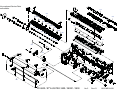
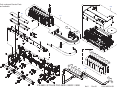
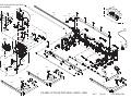
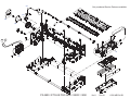
• Exploded Diagrams
• Circuit Diagrams
Symbols Used in this Manual
Various symbols are used throughout this manual either to provide additional
information on a specific topic or to warn of possible danger present during a
procedure or an action. Be aware of all symbols when they are used, and always read
NOTE, CAUTION, or WARNING messages.
Indicates an operating or maintenance procedure, practice or condition
that is necessary to keep the product’s quality.
Indicates an operating or maintenance procedure, practice, or condition
that, if not strictly observed, could result in damage to, or destruction of,
equipment.
May indicate an operating or maintenance procedure, practice or
condition that is necessary to accomplish a task efficiently. It may also
provide additional information that is related to a specific subject, or
comment on the results achieved through a previous action.
Indicates an operating or maintenance procedure, practice or condition
that, if not strictly observed, could result in injury or loss of life.
Indicates that a particular task must be carried out according to a certain
standard after disassembly and before re-assembly, otherwise the quality
of the components in question may be adversely affected.
Revision Status
Revision
Date of Issue
A
November 30, 2006
Description
First release
EPSON Stylus Pro 3800/3800C/3850
Revision A
Contents
Chapter 1 PRODUCT DESCRIPTION
1.1 Product Description ............................................................................................ 10
1.2 Basic Specifications ............................................................................................ 11
1.2.1 Basic Specifications ................................................................................... 11
1.2.2 Electric Specifications ............................................................................... 12
1.2.3 Environmental Characteristics ................................................................... 12
1.2.4 Reliability/Durability ................................................................................. 13
2.3 Ink Supply Mechanism .......................................................................................
2.3.1 Ink Flow Path .............................................................................................
2.3.2 Ink Pressurizing Mechanism .....................................................................
2.3.3 Ink Change System ....................................................................................
41
41
41
43
2.4 Cleaning Mechanism .......................................................................................... 44
2.5 Carriage Mechanism ........................................................................................... 46
2.5.1 Carriage Movement Mechanism ............................................................... 46
2.5.2 Platen Gap Adjustment Mechanism .......................................................... 47
1.3 Printing Specifications ........................................................................................ 14
1.3.1 Paper Feed Specifications .......................................................................... 14
1.3.2 Paper Feeder Specifications ....................................................................... 14
1.3.3 Paper Support ............................................................................................. 15
1.3.4 Printable Area ............................................................................................ 16
2.6 Paper Feed Mechanism ......................................................................................
2.6.1 Paper Feed Path .........................................................................................
2.6.2 Paper Loading Mechanism ........................................................................
2.6.3 Paper Feed Mechanism ..............................................................................
1.4 Print Mode .......................................................................................................... 17
1.4.1 Print Mode ................................................................................................. 17
1.4.2 Borderless Printing .................................................................................... 17
2.8 Other Mechanisms .............................................................................................. 57
1.5 Appearance Specifications ................................................................................. 19
1.5.1 Dimensions/Weight ................................................................................... 19
1.5.2 Part Names ................................................................................................. 19
1.6 Operation Panel ..................................................................................................
1.6.1 Buttons and Functions ...............................................................................
1.6.2 Buttons .......................................................................................................
1.6.3 LED ............................................................................................................
1.6.4 Panel Display .............................................................................................
1.6.5 Icons on the LCD .......................................................................................
1.6.6 Menu Settings ............................................................................................
1.6.7 Maintenance Mode ....................................................................................
1.6.8 Error/Warning Statuses Displayed/Indicated on/by LCD/LED ................
20
20
20
20
21
22
24
28
29
Chapter 2 OPERATING PRINCIPLES
48
48
49
52
2.7 Ink Mark Sensor ................................................................................................. 56
2.9 Outline of Circuit Boards ................................................................................... 58
2.9.1 Main Board ................................................................................................ 58
2.9.2 Power Supply Board .................................................................................. 59
2.10 Colorimetric Calibration (Color ID) Overview ................................................ 60
Chapter 3 TROUBLE SHOOTING
3.1 Overview ............................................................................................................ 62
3.1.1 Preliminary Check ..................................................................................... 62
3.1.2 Troubleshooting Procedure ........................................................................ 62
3.2 List of Panel Messages ....................................................................................... 63
3.3 Remedies for Warning Messages ....................................................................... 66
3.4 Remedies for Error Messages ............................................................................. 68
3.5 Remedies for Service Call Error ........................................................................ 74
3.6 Remedies for Print Quality Troubles .................................................................. 82
2.1 Overview ............................................................................................................ 36
2.2 Print Mechanism ................................................................................................. 40
6
EPSON Stylus Pro 3800/3800C/3850
Revision A
5.2.3 PG Position Adjustment .......................................................................... 201
Chapter 4 DISASSEMBLY & ASSEMBLY
4.1 Overview ............................................................................................................
4.1.1 Precautions .................................................................................................
4.1.2 Orientation Definition ................................................................................
4.1.3 Tools ..........................................................................................................
4.1.4 Screws ........................................................................................................
4.1.5 Chapter Organization .................................................................................
86
86
88
88
89
89
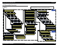
4.2 Disassembly Flowchart ...................................................................................... 90
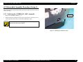
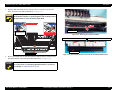
4.3 Disassembly/Assembly Procedure (Group 1) .................................................... 91
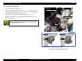
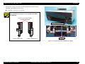
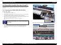
4.3.1 Unlocking the CARRIAGE, ASSY. manually .......................................... 91
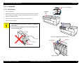
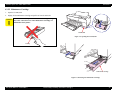
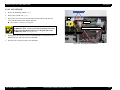
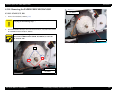
4.3.2 Consumable ............................................................................................... 92
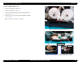
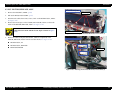
4.3.3 Removing the Housing and OPERATION, PANEL, ASSY. .................... 94
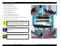
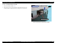
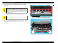
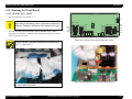
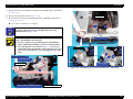
4.3.4 Removing the Circuit Boards .................................................................. 112
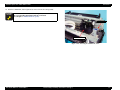
4.3.5 Removing the MOTOR ASSEMBLIES. ................................................. 118
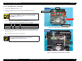
4.3.6 Removing the SENSORS and SWITCHES ............................................ 123
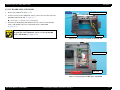
4.3.7 Removing the Carriage Mechanism ........................................................ 130
4.3.8 Removing the PAPER FEED MECHANISM ......................................... 132
4.3.9 Removing the Ink System Mechanism .................................................... 148
4.3.10 Removing the PAPER FEED MECHANISM ....................................... 164
4.3.11 Removing the Carriage Mechanism ...................................................... 169
4.3.12 Removing the INK SYSTEM MECHANISM ...................................... 176
4.3.13 PRINTER MECHANISM ..................................................................... 178
4.4 Disassembly/Assembly Procedure (Group 2) .................................................. 179
4.4.1 Removing the PAPER FEED MECHANISM ......................................... 179
Chapter 5 ADJUSTMENT
5.1 Overview ..........................................................................................................
5.1.1 Precautions ...............................................................................................
5.1.2 Adjustment Workflow .............................................................................
5.1.3 Parts and Units that Require Adjustments ...............................................
5.1.4 Required Adjustments by Part or Unit .....................................................
5.1.5 Description of Adjustments .....................................................................
5.1.6 Tools for Adjustments .............................................................................
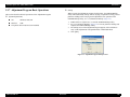
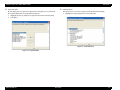
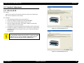
5.1.7 Adjustment Program Basic Operations ...................................................
191
191
191
191
192
193
195
196
5.2 Mechanical Adjustment .................................................................................... 198
5.2.1 PF Timing Belt Tension Adjustment ....................................................... 198
5.2.2 LD Roller Position Adjustment ............................................................... 200
5.3 Standard Adjustment ........................................................................................
5.3.1 RTC&USB ID .........................................................................................
5.3.2 Head Rank ID ..........................................................................................
5.3.3 Print Head Slant Adjustment (PF) ...........................................................
5.3.4 Print Head Slant Adjustment (CR) ..........................................................
5.3.5 Initial Ink Charge Flag ON/OFF .............................................................
5.3.6 Parameter Backup ....................................................................................
5.3.7 Check PG .................................................................................................
5.3.8 Initial Ink Charge .....................................................................................
5.3.9 Cleaning ...................................................................................................
5.3.10 Input Serial number ...............................................................................
5.3.11 Colorimetric Calibration Tool ...............................................................
5.3.12 Install F/W .............................................................................................
5.3.13 Ink Mark Sensor Adjustment for Auto Nozzle Check ..........................
5.3.14 Washing Head And Discharge Ink ........................................................
5.3.15 Auto Bi-D Adjustment ...........................................................................
5.3.16 Auto Uni-D Adjustment ........................................................................
5.3.17 Check the Release Of Grid Roller .........................................................
5.3.18 Check Network Communication ...........................................................
5.3.19 T&B&S Adjustment ..............................................................................
5.3.20 PF Adjustment .......................................................................................
5.3.21 EJ Adjustment ........................................................................................
5.3.22 Check Ink Selector Operation ................................................................
5.3.23 Write Constant When CR change ..........................................................
203
203
204
205
207
211
212
214
215
215
216
217
229
230
232
233
234
235
236
237
239
241
243
244
5.4 Check Results ...................................................................................................
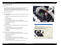
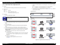
5.4.1 Check Nozzle ...........................................................................................
5.4.2 Print Image ..............................................................................................
5.4.3 Check Results ..........................................................................................
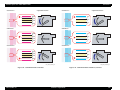
5.4.4 Check Alignment .....................................................................................
245
245
246
247
248
5.5 Reset Counters .................................................................................................. 249
Chapter 6 MAINTENANCE
6.1 Overview .......................................................................................................... 251
6.1.1 Product Life Information ......................................................................... 252
6.2 Cleaning ............................................................................................................ 253
6.3 Lubrication ....................................................................................................... 254
7
EPSON Stylus Pro 3800/3800C/3850
Revision A
Chapter 7 APPENDIX
7.1 Connectors ........................................................................................................ 263
7.2 Cables Connection Layout ............................................................................... 265
7.3 ASP List ............................................................................................................ 267
7.4 Exploded Diagrams .......................................................................................... 269
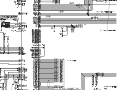
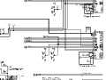
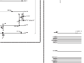
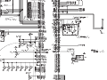
7.5 Circuit Diagrams .............................................................................................. 278
8
CHAPTER
1
PRODUCT DESCRIPTION
EPSON Stylus Pro 3800/3800C/3850
Revision A
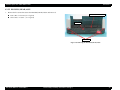
1.1 Product Description
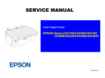
EPSON Stylus Pro 3800/3800C/3850 are large size color inkjet printers that support up
to A2 (17”) sized cut-sheet paper.
F-Mach (180N x 8-column) print head
Maximum print resolution (dpi): 2880 x 1440, Minimum dot: 3.5pl MSDT
Superior color and monochrome reproducibility with eight colors
HCD2 + K3 ink system, consisting of 4 basic colors (YMCK) with 2
complementary colors and 2 complementary blacks
80ml-size (injection volume) new ink cartridge
Automatic switching between black ink modes; Photo black and Matte black.
Requires no user intervention, and ink used during the conversion is remarkably
reduced.
Figure 1-1. External View
Two manual paper feeders are provided in addition to the ASF (Auto Sheet
Feeder)
Rear manual feeder: FA paper
Front manual feeder: Board paper (up to 1.5 mm thickness)
High speed network and communication supported
100BASE-TX/10BASE-T Network Interface
USB 2.0 High Speed Interface
Borderless printing supported
Clearly arranged buttons and a large LCD offer quick, easy operation
PRODUCT DESCRIPTION
Product Description
10
EPSON Stylus Pro 3800/3800C/3850
Revision A
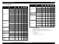
1.2 Basic Specifications
Table 1-1. Cartridge Alignment Sequence
1.2.1 Basic Specifications
Item
Specifications
Maximum paper width
17 inch (43 cm)
Printing method
On-demand ink jet method
Printing direction
Two-way shortest distance printing with logical seeking
Print Head
Ink
F-Mach
Number of nozzles
180 Nozzles per color (180 Nozzles x 8 colors)*
Type
HCD2 + K3 (9 independent ink cartridges)*
Color of inks
Matte Black*, Photo Black*, Light Black, Light Light
Black, Cyan, Magenta, Yellow, Light Cyan, Light Magenta
(Refer to Table 1-1 for the alignment sequence of the
cartridges)
2880 dpi x 1440 dpi
Smallest dot size
3.5 picoliters
Dot size
Refer to Table 1-2
Row 2
Row 3
Row 4
Row 5
Row 6
Row 7
Row 8
Row 9
Matte
Black
(MK)
Photo
Black
(PK)
Light
Black
(LK)
Light
Light
Black
(LLK)
Cyan
(C)
Magenta
(M)
Light
Cyan
(Lc)
Light
Magenta
(Lm)
Yellow
(Y)
Switched by an Ink
Selector
Type
Maximum print resolution
Row 1
Table 1-2. Dot Size
Dot Size
Printing
speed/area
Note *:
Alphanumeric
characters
Graphic mode
S (pl)
VSD1
22.2
13.8
6.6
VSD2
13.2
5.9
3.5
VSD3
--
--
3.5
Economy
22.2
--
--
Item
Specifications
Character quality
Fine
Character pitch
10 CPI
Printing area
167 digits
Printing speed
280 cps
Silent paper feeding
Automatic bottom processing
Table 1-4. Printing Speed and Area (Graphic Mode)
L/4 x 6 Photo high-speed printing
Automatic adjustment function
M (pl)
Table 1-3. Printing Speed and Area (Alphanumeric Characters)
Borderless printing
Printing function
L (pl)
Auto nozzle check
Auto Bi-d adjustment
Horizontal Resolution
(dpi)
Maximum Printing Area*
Printable Dots
Printing Speed
360
441.8 mm (17.39 inch)
6,262
280 cps
Refer to Table 1-3
720
441.8 mm (17.39 inch)
12,524
280 cps
Refer to Table 1-4
1440
441.8 mm (17.39 inch)
25,047
280 cps
2880
441.8 mm (17.39 inch)
50,094
280 cps
The all 9 ink cartridges can be installed simultaneously. The printer automatically switches
between Photo and Matte black depending on the driver selection while utilizing the same
physical ink channel.
PRODUCT DESCRIPTION
Note *:
Basic Specifications
Includes margins that bleed off the edges of paper. (max. 5 mm for both home and the opposite
sides.)
11
EPSON Stylus Pro 3800/3800C/3850
Revision A
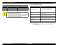
1.2.2 Electric Specifications
1.2.3 Environmental Characteristics
Specification
TEMPERATURE/HUMIDITY
Item
100/120V Model
220/240V Model
Rated voltage
100 to 120 VAC
220 to 240 VAC
Input voltage range
90 to 132 VAC
198 to 264 VAC
Rated frequency
50 to 60Hz
Input frequency range
Rated current
Operating
Power
consumption
Low-power mode*
S/W turned OFF
Operating
Storage*1
49.5 to 60.5Hz
0.6 A
0.3 A
Approx. 25 W
Approx. 25 W
Approx. 5 W
Approx. 5.5 W
Approx. 0.3 W
Approx. 0.4 W
Insulation resistance
10 M: or more
(between AC line and chassis at 500 VDC)
Dielectric strength
1.0 kVrms AC for 1 min. or 1.2 kVrms AC for 1 sec.
(between AC line and chassis)
Leak current
Condition
Note *:
Humidity*2
(non condensation)
10 to 35 °C
20 to 80 %
before unpacking
-20 to 60
°C*3
5 to 85 %
after unpacking
-20 to 40 °C*3
5 to 85 %
Note "*1": Includes condition during transportation.
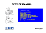
"*2": The combined temperature and humidity conditions must be within the blue-shaded range
shown in Figure 1-2.
"*3": Within 1 month under 40°C, within 120 hours under 60°C.
Humidity (%)
32
80
0.25 mA or less
Conforms to International Energy Star Program
Compliance with regulations
Temperature*2
(Category: conforms to the harmonic restraint measure
guideline)
Conforms to VCCI Class B
60
55
Shifting to low-power mode takes 15 min.
Normal
ambient
environment
The printer
allowable range
20
10 15 25 27
35
40
Temperature (°C)
Figure 1-2. Temperature/Humidity Range
PRODUCT DESCRIPTION
Basic Specifications
12
EPSON Stylus Pro 3800/3800C/3850
Revision A
1.2.4 Reliability/Durability
RESISTANCE TO VIBRATION/SHOCK
Vibration
Operating
0.15G, 10 to 55Hz
1G, within 1ms
Storage
0.50G, 10 to 55Hz
2G, within 2ms
C A U T IO N
Item
Shock
When transporting the printer, the print head must be capped,
and the ink cartridges must be removed.
If the print head is not capped with the power turned off, turn
the printer on with the ink cartridges installed, then turn it off
after confirming the print head is capped.
Target
Operating life of the printer
Until any one of the following conditions is met.
• 12,000 pages (A2 plain paper fine mode)
• 1,600,000 paths (carriage movement)
• 5 years
MPBF
Black: 300 pages or more*1
Color: 150 pages or more*2
MTBF
20,000 POH*3
(No faults with electronic parts and fans)
Battery life
5 to 10 years
Extension of normal TCL
generation time
4,320 hours (6 months) printing time within 2 hours
360 hours (15 days) printing time over 2 hours
Simultaneous use of CL timer T1
and FL timer Tf
Execution
Periodical flushing
Every 1 hour
Note "*1": A4-sized paper, ECMA Pattern printing
"*2": Approx. 5% coverage
"*3": Total print time of 850 hours in normal ambient temperature, approx. 10% coverage.
(POH = Power on hours)
PRODUCT DESCRIPTION
Basic Specifications
13
EPSON Stylus Pro 3800/3800C/3850
Revision A
1.3 Printing Specifications
1.3.1 Paper Feed Specifications
Item
Specification
Paper feed method
Friction feed
Minimum pitch of paper feed
2.94 Pm (1/8640 inch)
Paper feed speed
25.4 mm (1 inch) when line feed: 333 msec (3 inch/sec)
1.3.2 Paper Feeder Specifications
EPSON Stylus Pro 3800/3800C/3850 support three types of paper feeding methods;
ASF, Rear Manual Feed, and Front Manual Feed. The paper size and thickness for each
of the methods are shown in the table below. For paper type and feeder capacity, refer
to "1.3.3 Paper Support" (p15).
Paper Size
Paper Feed
Method
Width (mm)
Length (mm)
Standard paper
(mm)
Thickness
(mm)
ASF
89 to 431.8
127 to 950
L/4”x6” to A2/USC
0.08 to 0.27
Rear Manual Feed
210 to 431.8
279.4 to 950
A4/LTR to A2/USC
0.29 to 0.5
Front Manual Feed
210 to 420
279.4 to 594
A4/LTR to A2
1.2 to 1.5
PRODUCT DESCRIPTION
Printing Specifications
14
EPSON Stylus Pro 3800/3800C/3850
Revision A
1.3.3 Paper Support
Media Name
Premium Glossy Photo
Paper
Premium Semigloss
Photo Paper
Premium Luster Photo
Paper
Singleweight Matte
Paper
Photo Quality Ink Jet
Paper
(KANZAN for EU A4
only, ESF for others)
Proofing Paper
Semimatte
(Commercial
Semimatte)
Media Name
Size (mm)
Feeder Borderless Black
EAI EU Asia
(capacity*1) print*2 Ink*3
L (3R)
(89 x 127)
ASF (20)
P
5” x 7”
(127 x 178)
ASF (20)
P
16:9 wide (102 x 148)
ASF (20)
P
8” x 10”
(203 x 254)
ASF (20)
P
4” x 6”
(102 x 152)
ASF (20)
P
11” x 14” (279 x 356)
ASF (10)
P
Letter
(216 x 279)
ASF (20)
P
A4
(210 x 297)
ASF (20)
P
A3
(297 x 420)
ASF (10)
P
S-B/A3+
(329 x 483)
ASF (10)
P
A2
(420 x 594)
ASF (1)
P
USC
(432 x 559)
ASF (1)
P
4” x 6”
(102 x 152)
ASF (20)
P
Letter
(216 x 279)
ASF (20)
P
A4
(210 x 297)
ASF (20)
P
A3
(297 x 420)
ASF (10)
P
S-B/A3+
(329 x 483)
ASF (10)
P
A2
(420 x 594)
ASF (1)
P
Letter
(216 x 279)
ASF (20)
P
A3
(297 x 420)
ASF (10)
P
S-B/A3+
(329 x 483)
ASF (10)
P
USC
(432 x 559)
ASF (1)
P
S-B/A3+
(329 x 483)
ASF (50)
NA
M
A4
(210 x 297)
ASF (100)
NA
P/M
(216 x 279)
ASF (100)
NA
P/M
Legal
(216 x 358)
ASF (50)
NA
P/M
USB
(279 x 432)
ASF (50)
NA
P/M
S-B/A3+
(329x483)
ASF (1)
NA
P
PRODUCT DESCRIPTION
Watercolor PaperRadiant White
UltraSmooth Fine Art
Paper
Letter
Enhanced Matte Paper
(EAI)/Archival Matte
Paper
(EU, Asia)
Size (mm)
Feeder Borderless Black
EAI EU Asia
(capacity*1) print*2 Ink*3
Letter
(216x279)
ASF (20)
M
A4
(210x297)
ASF (20)
M
A3
(297x420)
ASF (10)
M
S-B/A3+
(329x483)
ASF (10)
M
A2
(420x594)
ASF (1)
M
USC
(432x559)
ASF (1)
M
S-B/A3+
(329x483)
R.Manual
(1)
M
A3+
(329x483)
R.Manual
(1)
M
A2
(420x594)
R.Manual
(1)
M
USC
(432x559)
R.Manual
(1)
M
Letter
(216x279)
R.Manual
(1)
M
S-B/A3+
(329x483)
R.Manual
(1)
M
A2
(420x594)
R.Manual
(1)
M
USC
(432x559)
R.Manual
(1)
M
Velvet Fine Art Paper
Note "*1": ASF = Auto Sheet Feeder
R.Manual = Rear Manual Feed
Front Manual Feed supports thicker paper (1.2 to 1.5mm thickness).
Paper loading capacity for both Rear and Front Manual Feed is one sheet.
"*2": User-defined sized paper (89 x 127mm to 432 x 950mm) is not available for borderless
printing.
"*3": Shows the supported black ink type
P:
Photo Black
M: Matte Black
P/M: Both Photo and Matte Black are supported
Printing Specifications
15
EPSON Stylus Pro 3800/3800C/3850
Revision A
1.3.4 Printable Area
PW
Dimension
PW (paper width)
89mm to 431.8mm
PL (paper length)
127mm to 950mm
TM (top margin)
0mm/3mm/20mm*
BM (bottom margin)
0mm/3mm/20mm*
LM (left margin)
0mm/3mm
RM (right margin)
0mm/3mm
Note *:
LM
RM
TM
TM and BM are fixed to 20 mm in front manual feeding.
The printer detects the paper width when paper is set. (If the paper width detection
setting is OFF, the printer does not detect the paper width.)
The printer does not print the image exceeding the detected paper width and the
printable area that is specified in the paper setting. (If the paper width detection
setting is OFF, the printer may print on the platen.)
Paper Feed Direction
Item
PL
Printable Area
The top/bottom/left/right margins (TM, BM, LM, RM) can be set to zero under
special conditions.
Because the printer detects tilt of loaded paper in a range of 3 mm at both left and
right sides, an image bleeds off both left and right edges of paper by 3 mm each at
borderless printing. However, if the distance between the paper edges and the
platen (sponge width) is less than 3 mm, the bleeding margins are adjusted to less
than 3 mm (within the range of 0 mma3 mm) not to directly print on the platen.
(Refer to "1.4.2 Borderless Printing" (p17), for the borderless print specification.)
PRODUCT DESCRIPTION
Printing Specifications
BM
Figure 1-3. Printable Area
16
EPSON Stylus Pro 3800/3800C/3850
Revision A
Table 1-5. Borderless Printing Available Paper Sizes
1.4 Print Mode
Paper Size Displayed by Driver
This section provides specifications of the print mode and borderless printing.
A4 (210 x 297 mm)
Available
A3 (297 x 420 mm)
Available
Super A3 (329 x 483 mm)
Available
A2 (420 x 594 mm)
Available
B5 (182 x 257 mm)
NA
VSD1_Eco (280cps)
B4 (257 x 364 mm)
NA
NA
1.4.1 Print Mode
Media Type
Plain Paper
Inkjet Paper
Print Quality
Draft
Dot Size
Normal (360 dpi)
720 x 360 dpi
VSD1 (280cps)
B3 (364 x 514 mm)
Normal (360 dpi)
720 x 360 dpi
VSD1 (280cps)
89 x 127 mm (3.5 x 5 in)
Available
Fine (720 dpi)
720 x 720 dpi
VSD1 (280cps)
102 x 152 mm (4 x 6 in)
Available
Super Fine (1440 dpi)
1440 x 720 dpi
VSD2 (280cps)
127 x 178 mm (5 x 7 in)
Available
2880 x 1440 dpi
VSD3 (280cps)
16:9 wide (102 x 181 mm)
Available
1440 x 1440 dpi
VSD2 (280cps)*1
203 x 254 mm (8 x 10 in)
Available
2880 x 2880 dpi
(280cps)*2
254 x 305 mm (10 x 12 in)
Available
279 x 356 mm (11 x 14 in)
Available
Super Photo (2880 dpi)
--
Print Density
(H x V)
360 x 360 dpi
Borderless Print
ISV Square Resolution Mode
VSD3
Note "*1": Driver not supported
"*2": Driver not supported (supports Out_bit_1 only)
1.4.2 Borderless Printing
305 x 305 mm (12 x 12 in)
NA
406 x 508 mm (16 x 20 in)
Available
User Defined*
Note *:
AVAILABLE PAPER SIZE
NA
The minimum user defined size is 3.5 x 5 in (89 x 127 mm), and the maximum size is 17 x 37.4
in (432 x 950 mm).
The following table lists paper sizes in the order shown by the printer driver, and shows
the borderless printing availability.
Table 1-5. Borderless Printing Available Paper Sizes
Paper Size Displayed by Driver
Borderless Print
Letter (8 2/1 x 11 in)
Available
Legal (8 2/1 x 14 in)
NA
Half Letter (5 2/1 x 8 2/1 in)
NA
US B (11 x 17 in)
Available
US C (17 x 22 in)
Available
A6 (105 x 148 mm)
NA
A5 (148 x 210 mm)
NA
PRODUCT DESCRIPTION
Print Mode
17
EPSON Stylus Pro 3800/3800C/3850
Revision A
AUTOMATIC EXPANSION SPECIFICATION
PRINTABLE AREA
The driver automatically changes margins that bleed off the edges of paper according
to the paper size.
Printing position coordinate origin
Width-direction
printable area
Table 1-6. Borderless Printing Margins (Bleed)
3.5m (max)
Top
1.34mm (19dot)
Left/Right
Bottom
Note :
4.02mm (57dot)
A2/USC
Page control
coordinate origin
Paper edge
2.96mm (42dot)
2.54mm (36dot)
2.54mm (36dot)
11” x 14”
A3/A3+
3.32mm (47dot)
3.46mm (49dot)
4.52mm (64dot)
4.52mm (64dot)
5.01mm (71dot)
Printable area
The number of dots are based on 360 dpi.
Bottom position
L/4” x 6”
Length-direction
printable area
16:9 Wide
5” x 7”
8” x 10”
A4 / Letter
Paper width
Paper
feeding
direction
5mm (max)
5mm
(max)
5mm
(max)
Figure 1-4. Printable Area
Note :
PRODUCT DESCRIPTION
Print Mode
Print start position can be shifted toward the home position by 8 m by changing the appropriate
setting.
18
EPSON Stylus Pro 3800/3800C/3850
Revision A
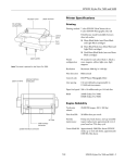
Dimensions
Storage: 684 (W) x 376 (H) x 257 (D) mm
Printing: 684 (W) x 1040 (H) x 550 (D) mm
1.5 Appearance Specifications
This section describes external dimensions and parts names.
Weight
1.5.1 Dimensions/Weight
18.5 kg (excluding ink cartridges, including Maintenance cartridge)
19.8 kg (including ink cartridges)
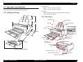
1.5.2 Part Names
Paper Support
293 mm
Auto Sheet Feeder
550 mm
Paper Support Edge
Guide
Edge Guide
684 mm
Top Cover
257 mm
Ink Cover
100 mm
376 mm
Print Head (Nozzle)
1040 mm
Operation Panel
Paper Eject
Tray
Maintenance Cartridge Cover
Board Paper Tray
Paper Eject
Tray Cover
Exhaust Outlet
Rear Paper
Feeder
90 mm
Figure 1-5. External Dimensions
USB Interface Connector
Network Interface Connector
AC Connector
Figure 1-6. Parts Names
PRODUCT DESCRIPTION
Appearance Specifications
19
EPSON Stylus Pro 3800/3800C/3850
Revision A
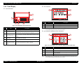
1.6 Operation Panel
Functions
Button
1.6.1 Buttons and Functions
A
Power LED
B
1
Back/Left
Paper status LED
C
2
Ink status LED
Ink Cover Open/Up
Paper Feed/
Down
6
7
3
5
6
Power
4
Cancel/Reset
7
Enter
Menu/Right
Normal One Press
Hold Down for
3 Seconds
• When paper is set
ASF: Ejects the paper
Manual-Rear: Backfeeds the paper
Manual-Front: Ejects the paper
• When paper is not set
ASF starts paper feeding
• When Manual-Front Tray Cover is
opened.
Manual-Front starts paper feeding
--
Set Value -
--
• Accepts the change
of setting
• Executes the
selected operation
• Saves the setting
Enter
--
Note "*1": The printer is always turned OFF regardless of operation status.
"*2": When turning the power ON while holding down the Cancel button, the maintenance mode
becomes activated. (Refer to "1.6.7 Maintenance Mode" (p28) for details.)
"*3": Deactivated during printing.
Paper Feed/Down
1.6.3 LED
Figure 1-7. Operation Panel
1.6.2 Buttons
LED
Color
1
2
3
Power
Cancel/Reset*2
Menu/Right
Normal One Press
Turns the power ON or OFF*1
• Clears error
• Opens I/H Cover
(When the printer runs out of ink)
• During printing
Changes the panel display to the
Printer Status Menu
• When not printing
Shifts the printer into the Panel
Setting Mode
4
Back/Left
--
5
Ink Cover Open/
Up
--
PRODUCT DESCRIPTION
Hold Down for
3 Seconds
-Cancels the job
Runs a head
cleaning*3
Displays
ON
Functions
Button
Function at the
Panel Setting
Function at the
Panel Setting
A
Power
Green
Power OFF
Interrupts panel setting
B
Paper status
Red
Moves to the next
menu item (Descent)
C
Ink status
Red
Flashing*
Unlocks the Ink
Cover
Moves to the previous
menu item (Ascent)
Set Value +
Receiving data, during printing, or executing power off
sequence.
OFF
The power is OFF.
ON
Impossible to make a print due to the paper status.
Flashing*
• A paper feeding or ejecting error is occurring.
• A maintenance call error is occurring.
OFF
The papers are in normal condition without an error or
warning.
ON
An ink-related error is occurring.
Flashing*
OFF
--
Status
The power is ON.
An ink-related warning is occurring.
The inks are in normal condition without an error or
warning.
Note *: Alternately turns On and Off every 500 ms. In the case of maintenance call error, they light for 100
ms at intervals of five seconds.
Note :
Operation Panel
When a service call error occurs, all the LEDs flash.
20
EPSON Stylus Pro 3800/3800C/3850
Revision A
Error indication
1.6.4 Panel Display
Normal indication
2
1
3
1
2
6
Figure 1-9. Panel Display (Error indication)
No.
3
4
5
Figure 1-8. Panel Display (Normal indication)
No.
Item
Description
Messages
Printer status, operation status, and error messages are displayed.
2
User-defined paper No.
The user-defined paper setting number created by the CUSTOM
PAPER function in the panel setting menu is displayed.
3
Paper type
(For Cut-sheet only)
This icon is displayed when the number of paper, except STANDARD
paper, created by the CUSTOM PAPER function in the panel setting is
selected.
4
Platen Gap
The platen gap setting made by the PLATEN GAP function in the
panel setting menu is indicated.
5
Ink Cartridge Status
The remaining amount of ink in each cartridge is displayed.
6
Remaining
Maintenance Cartridge
Status
Free space of the Maintenance Cartridge is displayed.
Description
1
Error name
Error name is highlighted.
2
Error icon
Error icon is displayed.
3
Remedy
Describes the cause of error and gives instructions to clear the error.
Note :
1
Item
When multiple errors occur simultaneously, they are displayed in the order of precedence. The
next error indication appears when previous one is cleared.
Error indication (Displayed with an illustration)
2
1
3
4
Figure 1-10. Panel Display (Error indication: Displayed with an illustration)
No
Description
1
Error name
Error name is highlighted.
2
Error icon
Error icon is displayed
3
Illustration
Describes the cause of the error and gives instructions to clear the error
using a illustration.
4
Remedy
Describes the cause of the error and gives instructions to clear the error.
Note :
PRODUCT DESCRIPTION
Item
Operation Panel
When multiple errors occur simultaneously, they are displayed in the order of precedence. The
next error indication appears when previous one is cleared.
21
EPSON Stylus Pro 3800/3800C/3850
Revision A
1.6.5 Icons on the LCD
Table 1-7. Relation between Counters and Remaining Ink
PLATEN GAP SETTING
The platen gap specified in PRINTER SETUP and CUSTOM PAPER menus is
indicated with icons as shown below.
Remaining Ink
(%)
No.
Remaining Ink
(%)
No.
Remaining Ink
(%)
No.
Remaining Ink
(%)
0*1
Not selected K
6
67-72
11
39-44
16
12-16
1
95-100
7
62-66
12
34-38
17
6-11
2
89-94
8
56-61
13
28-33
18
1-5
Ink Out
Ink Cartridge
Error
3
84-88
9
51-55
14
23-27
19*2
STANDARD is selected.
4
78-83
10
45-50
15
17-22
20
NARROW is selected.
5
73-77
Icons
Status
--
No.
Note "*1": Displays either Matte BK or Photo BK that is not in use when printing.
"*2": Counter No.19 is displayed when non-genuine ink cartridge(s) is used.
Ink Low/Ink Out Indicator
WIDE is selected.
The indicators below is displayed when Ink becomes Low or Out.
No.
1
2
3
4
5
6
7
8
9
PK
C
LK
Lc
LLK
Lm
M
MK
Y
WIDER is selected.
Icon
(Ink Low)
WIDEST is selected.
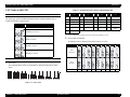
INK CARTRIDGE STATUS
Icon
(Ink Out)
Ink Counter
The remaining amount of ink in each cartridge is indicated on the panel as shown
below.
Colors
0
1
2
3
4
5
6
7
8
9 10 11 12 13 14 15 16 17 18 19 20
Figure 1-11. Ink Counter
PRODUCT DESCRIPTION
Operation Panel
22
EPSON Stylus Pro 3800/3800C/3850
Revision A
MAINTENANCE CARTRIDGE STATUS
Maintenance Cartridge Counter
The free space of the Maintenance Cartridge is indicated as shown below.
Figure 1-12. Maintenance Cartridge Status
Table 1-8. Relation between Counters and Remaining Ink
No.
Free Space (%)
No.
Free Space (%)
No.
Free Space (%)
1
2
96-100
9
58-61
17
20-23
91-95
10
53-57
18
15-19
3
86-90
11
48-52
19
10-14
4
81-85
12
43-47
20
5-9
5
77-80
13
39-42
21
1-4
6
72-76
14
34-38
22
0
7
67-71
15
29-33
23
Full
8
62-66
16
24-28
PRODUCT DESCRIPTION
Operation Panel
23
EPSON Stylus Pro 3800/3800C/3850
Revision A
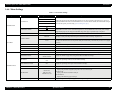
1.6.6 Menu Settings
Table 1-9. List of Menu Settings
Top Menu
Menu Items
Settings (Bold = default)
Explanation
NARROW
STANDARD
PLATEN GAP
Adjusts the gap between the print head and the platen. The set value is returned to the default at every power-on.
When the PAPER TYPE in the CUSTOM PAPER menu is set to other than the default, the PLATEN GAP setting in
the menu takes priority over this setting. (see "PG settings list" (p27))
WIDE
WIDER
PRINTER SETUP
WIDEST
ON
PAPER SIZE CHECK
INITIALIZE SETTINGS
Setting to OFF deactivates the sensor that detects paper width when paper is loaded. This enables to print on paper
whose width is out of the sensor’s detectable range, however, the user should know that if he/she prints an image
larger than the paper size, the image extended off the edges of the paper is printed directly on the platen.
OFF
EXECUTE
All settings made using the control panel are returned to their default.
MANUAL
Prints a nozzle check pattern, firmware version, usage count of paper and ink, and free space in the maintenance
cartridge. Visually check the printed check pattern, and decide whether cleaning is required or not.
NOZZLE CHECK
Prints a nozzle check pattern, firmware version, usage count of paper and ink, and free space in the maintenance
cartridge. The ink mark sensor scans the printed check pattern and cleaning is automatically carried out if it is judged
necessary.
AUTO
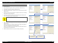
TEST PRINT
STATUS SHEET
PRINT
Prints information on the printer status.
NETWORK STATUS SHEET
PRINT
Prints information on the network status.
JOB INFORMATION
PRINT
Prints information on print jobs stored in the printer up to 10 jobs.
PRINT
Prints setting values set in the CUSTOM PAPER menu.
CUSTOM PAPER
VERSION
PRINTABLE PAGES
INK LEVEL
MAINTENANCE TANK
PRINTER STATUS
USAGE COUNT
JOB HISTORY
TOTAL PRINTS
PRODUCT DESCRIPTION
o0XXXX-XX.XX.ICBS
Displays the firmware version installed on the printer. (see "Firmware version indication" (p27))
(Ink color)
nnnnnnn PAGES
Displays the number of pages that can be printed with the installed ink cartridge.
(Ink color)
nn%
Displays the percentage of ink level in each installed cartridge.
(MAINTENANCE TANK)
nn%
INK xxxxx.xml
No.0 to No.9
INK xxxxx.xml
PAPER xxxx.x cm2
nnnnnn PAGES
Displays the percentage of free space in the maintenance cartridge.
Displays ink amount consumed in ml units.
JOB NO.
Displays the job number assigned by the printer. The No.0 is the latest job.
INK LEVEL
Displays ink amount consumed for each job.
PAPER SIZE
Displays the number of pages of each job.
Displays the gross number of printed pages in decimal up to six digits.
Operation Panel
24
EPSON Stylus Pro 3800/3800C/3850
Revision A
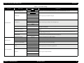
Table 1-9. List of Menu Settings
Top Menu
Menu Items
PAPER NUMBER (1-10)
Settings (Bold = default)
Explanation
STANDARD
Paper type and relating settings can be saved and easily retrieved by assigning a number to them. Up to 10 groups of
settings can be stored. When EPSON genuine paper is used, STANDARD should be selected.
PAPER NO.1-10
MATTE THICK
MATTE THIN
PAPER TYPE
PHOTO PLAIN
Selects a paper type corresponds to the paper.
FINE ART PAPER
REMOTE PANEL PAPER
NARROW
STANDARD
CUSTOM PAPER
PLATEN GAP
Adjusts the platen gap according to the selected paper type.
WIDE
WIDER
THICKNESS PATTERN
Prints a pattern to detect the thickness of loaded paper. (When STANDARD is selected in the PAPER NUMBER,
this menu is not displayed.)
PRINT
0.00%
PAPER FEED ADJUST A
Sets paper feed amount for the printable area. The amount increases/decreases by the selected percentage of one
meter.
-0.7% to 0.7%
0.00%
PAPER FEED ADJUST B
Sets paper feed amount for the bottom area (out of the printable area). The amount increases/decreases by the
selected percentage of one meter.
-0.7% to 0.7%
0.0 SEC
DRYING TIME
MAINTENANCE
Sets a time period to stop the print head movement for drying ink.
0.0 SEC to 10.0 SEC
BLACK INK CHANGE
EXECUTE
Switches the black ink between Matte and Photo.
POWER CLEANING
EXECUTE
Performs a power cleaning.
CLOCK SETTING
CONTRAST ADJUSTMENT
YY/MM/DD HH:MM
Sets date and time of the internal clock.
0
Adjusts the contrast of the control panel display.
-20 - 0 - +20 (dec)
PREM.GLOSSY/LUSTER
AUTO
PQ INK JET PAPER
Selects a paper type to be used for the gap adjustment.
ENHANCED MATTE PAPER
0.1 mm
HEAD ALIGNMENT
0.2 mm
MANUAL
0.3 mm
Selects a gap to be adjusted manually.
0.4 mm
0.5 mm
PRODUCT DESCRIPTION
Operation Panel
25
EPSON Stylus Pro 3800/3800C/3850
Revision A
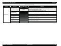
Table 1-9. List of Menu Settings
Top Menu
Menu Items
NETWORK SETUP
Settings (Bold = default)
Explanation
DISABLE
Disables or enables a network connection. The other NETWORK SETUP menu items appear only when ENABLE
has been selected. Under the following conditions, this setting is automatically changed to DISABLE.
• Every power-on (always returns to the default: DISABLE)
• When the network setup initialization is performed.
• When the PANEL DEFAULT in the maintenance mode is performed.
ENABLE
AUTO
IP ADDRESS SETTING
PANEL
Select the settings for the IP address to use.
When [PANEL] is selected, the settings in [IP, SN, DG SETTING] are enabled.
PING
NETWORK SETUP
IP, SN, DG SETTING
APPLE TALK
MS NETWORK
BONJOUR
INIT NETWORK SETTING
PRODUCT DESCRIPTION
--ON
OFF
ON
OFF
ON
OFF
EXECUTE
Set the IP address, Subnet mask, and default gateway.
Enables (ON)/disables (OFF) AppleTalk.
Enables (ON)/disables (OFF) MS NETWORK.
Enables (ON)/disables (OFF) BONJOUR.
Returns the network I/F related settings to their default.
Operation Panel
26
EPSON Stylus Pro 3800/3800C/3850
Revision A
PG settings list
Firmware version indication
The table below lists the platen gap amounts settable with the printer driver, control
panel, and media table.
The table below explains the meaning of the “o0XXXX-xx.xx.IBC” (firmware
version).
Table 1-10. PG Setting List
Printer Driver
Paper Thickness
setting
Control Panel
Setting
NARROW
STANDARD
No setting
0.0 to 0.8mm
WIDE
WIDER
WIDEST
0.9mm to 1.5mm
--
PRODUCT DESCRIPTION
Table 1-11. Firmware Version Indication
Media Table or
Printer Driver
PG Setting
PG amount (mm)
Item
Minimum
0.9
Small
0.9
Middle
1.2
Large
1.5
Minimum
0.9
Small
1.2
Middle
1.5
Large
2.1
Minimum
1.2
Small
1.5
Middle
2.1
o0
Large
2.1
Minimum
1.5
Small
2.1
Middle
2.1
Large
2.1
Minimum
2.1
Small
2.1
Middle
2.1
Large
2.1
--
3.5
XXXX
xx.xx
Operation Panel
Explanation
A code assigned to each printer.
Special version is assigned to “0” (zero).
The version of the firmware installed on the printer.
The version of the network firmware.
I
A code assigned by product. The code of the printer is “8”.
B
When the business system functions are enabled, the printer settings are
indicated in hexadecimal (1 to F).
bit0: Graphic printing control function.
0: Disabled
1: Enabled
bit1: Credit function
0: Disabled
bit2: Credit counter
0: The credit function is disabled or the counter is “0” (zero).
1:The credit function is enabled and the counter is 1 or more.
bit3: Reserved
C
Shows the custom number when the custom operation has been set using
the special setting menu. “0” appears when such operation is not set.
27
EPSON Stylus Pro 3800/3800C/3850
Revision A
1.6.7 Maintenance Mode
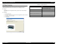
HOW TO START & QUIT
Starting Method
Turn the printer On while holding down the Cancel/Reset button.
Quitting Method
Turn the printer Off.
MAINTENANCE MODE MENU LIST
Menu Item
Settings
(Bold = default)
Explanation
ENGLISH
JAPANESE
FRENCH
LANGUAGE
GERMAN
ITALIAN
Select the language to be displayed on the
LCD panel.
PORTUGUE
SPANISH
DUTCH
UNIT
DEFAULT PANEL
METRIC
FEET/INCH
EXECUTE
PRODUCT DESCRIPTION
Select a unit of length to be used for various
length information.
All settings made in the following menus are
returned to their default.
PRINTER SETUP menu
PRINTER STATUS menu
CUSTOM PAPER menu
HEAD ALIGNMENT menu
NETWORK SETUP menu
Operation Panel
28
EPSON Stylus Pro 3800/3800C/3850
Revision A
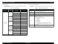
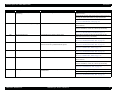
1.6.8 Error/Warning Statuses Displayed/Indicated on/by LCD/LED
No
Error/Warning Status
Error or
Warning
LED
Illustration
on LCD
Message on LCD
Power
Paper Status
Ink Status
Light
Blink
Blink
1
FATAL ERROR (Service Call No. is displayed)
Error
--
SERVICE CALL ERROR
NNNN
PLEASE CONTACT TO THE
REPAIR CENTER
2
FATAL ERROR
(1st time: Restart Request is displayed/ 2nd time and later: Service Call
No. is displayed.)
Error
--
PRINTER ERROR
RESTART THE PRINTER
Light
Blink
Blink
3
FATAL ERROR
(Always Restart Request is displayed.)
Error
--
PRINTER ERROR
RESTART THE PRINTER
Light
Blink
Blink
4
FATAL ERROR
(CR locked)
Error
--
CARRIAGE LOCKED
RELEASE THE CARRIAGE
LOCK
Light
Blink
Blink
5
PAPER JAM
(Fatal Error)
Error
--
PAPER JAM
CLEAR JAMMED PAPER
SEE PRINTER GUIDE
FOR INSTRUCTIONS
Light
Blink
Blink
6
Timer IC Reset/Clearing NVRAM (Please wait)
--
--
PLEASE WAIT
Light
Light
Light
7
Updating F/W (at normal startup)
--
--
UPDATING FIRMWARE
Blink
Off
Off
8
Canceling (including Job Cancel)
--
--
RESETTING
PLEASE WAIT
Light
Light
Light
9
No Maintenance Cartridge
Error
NO MAINTENANCE CART.
INSTALL THE
MAINTENANCE
CARTRIDGE.
Light
Off
Light
10
Maintenance Cartridge Cover Open
Error
MAINTENANCE COVER
OPEN
CLOSE THE
MAINTENANCE COVER
Light
Off
Light
11
Paper Feed Failed
Reset
Error
--
PAPER FEED ERROR
REMOVE PAPER
AND LOAD PAPER
CORRECTLY
Light
Light
Off
12
Board Paper Feed Failed
Reset
Error
--
PAPER FEED ERROR
LOAD PAPER CORRECTLY
AND PRESS PAPER/FEED
BUTTON
Light
Light
Off
PRODUCT DESCRIPTION
Operation Panel
29
EPSON Stylus Pro 3800/3800C/3850
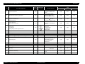
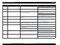
No
Error/Warning Status
13
Paper Jam Discharge Failed
Remove Paper
14
Waiting Cartridge Cover open
15
Cartridge Cover Cannot Be Opened
16
Detecting Ink Cartridge (Cover close -> READY)
Revision A
Error or
Warning
Illustration
on LCD
Error
--
--
Power
Paper Status
Ink Status
PAPER JAM
REMOVE PAPER
Light
Light
Off
--
RELEASING THE
INK COVER LOCK
Blink
Off
Off
Error
--
CANNOT OPEN COVER
IS THERE ANYTHING ON
THE PRINTER?
PRESS THE UP BUTTON
Light
Off
Blink
--
--
PLEASE WAIT
Light
Off
Off
MAINTENANCE
CARTRIDGE
NEARLY FULL
REPLACE THE
CARTRIDGE
Light
Off
Light
NOT ENOUGH INK
REPLACE INK CARTRIDGE
WITH A NEW ONE
Light
Off
Light
MAINTENANCE
CARTRIDGE
ERROR
REPLACE THE
CARTRIDGE
Light
Off
Light
--
MAINTENANCE
PLEASE USE GENUINE
EPSON CARTRIDGES
Light
Off
Light
--
MAINTENANCE
NON-GENUINE CARTRIDGE!
MAY NOT PERFORM AT
OPTIMUM. CONTINUE?
<YES
NO>
Light
Off
Light
--
MAINTENANCE
THIS MAY VOID EPSON’S
WARRANTY.
DO YOU ACCEPT THIS?
<ACCEPT
DECLINE>
Light
Off
Light
MAINTENANCE
CARTRIDGE
FULL
REPLACE THE
CARTRIDGE
Light
Off
Light
17
Maintenance Cartridge Insufficient
Error
18
Ink Cartridge Insufficient
Error
19
Maintenance Cartridge CSIC Read/Write Error
Error
20
Not GENUINE maintenance cartridge error
Error
21
22
23
Not GENUINE maintenance cartridge error (Confirmation 1)
Not GENUINE maintenance cartridge error (Confirmation 2)
Maintenance Cartridge End
PRODUCT DESCRIPTION
LED
Message on LCD
Error
Error
Error
--
Operation Panel
30
EPSON Stylus Pro 3800/3800C/3850
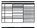
No
Error/Warning Status
24
Board paper removal error
25
Board Paper Tray Open Error
The tray was opened during operation
Revision A
Error or
Warning
LED
Illustration
on LCD
Message on LCD
Power
Paper Status
Ink Status
Error
FRONT FEED SLOT OPEN
PRESS THE
DOWN BUTTON
AND REMOVE
PAPER
Light
Light
Off
Error
FRONT FEED SLOT OPEN
CLOSE THE
FRONT MANUAL
FEED SLOT
Light
Light
Off
Light
Light
Off
26
Board tray open error
Set paper
Error
FRONT FEED SLOT OPEN
LOAD
MEDIA AND
PRESS THE
DOWN BUTTON
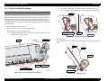
27
Board Tray Close Error
The tray was opened during operation
Error
FRONT SLOT CLOSED
OPEN THE
FRONT MANUAL
FEED SLOT
Light
Light
Off
28
Board Tray Close Error
Paper needs to be removed
Error
FRONT SLOT CLOSED
OPEN THE
FRONT MANUAL
FEED SLOT
Light
Light
Off
29
No Ink Cartridge
Error
--
NO INK CARTRIDGE
INSTALL INK CARTRIDGE
Light
Off
Light
30
Ink Cartridge CSIC Read/Write Error
Error
--
INK CARTRIDGE ERROR
REPLACE CARTRIDGE
Light
Off
Light
31
Not GENUINE ink cartridge error
Error
--
INK CARTRIDGE
PLEASE USE GENUINE
EPSON INK CARTRIDGE
Light
Off
Light
--
INK CARTRIDGE
NON-GENUINE CARTRIDGE!
MAY NOT PERFORM AT
OPTIMUM. CONTINUE?
<YES
NO>
Light
Off
Light
Light
Off
Light
Light
Off
Light
32
Not GENUINE ink cartridge error (Confirmation 1)
Error
33
Not GENUINE ink cartridge error (Confirmation 2)
Error
--
INK CARTRIDGE
THIS MAY VOID EPSON’S
WARRANTY.
DO YOU ACCEPT THIS?
<ACCEPT
DECLINE>
34
Ink End
Error
--
INK CARTRIDGE
REPLACE INK CARTRIDGE
PRODUCT DESCRIPTION
Operation Panel
31
EPSON Stylus Pro 3800/3800C/3850
No
Error/Warning Status
Revision A
Error or
Warning
Illustration
on LCD
Error
--
LED
Message on LCD
Power
Paper Status
Ink Status
INK COVER OPEN
CLOSE THE INK COVER
Light
Off
Light
35
Ink Cover Open
36
Ink Initial Refilling
--
--
CHARGING INK
NN%
Blink
Off
Off
37
K Ink Changing
--
--
BLACK INK CHANGING
MATTE -> PHOTO NN%
Blink
Off
Off
38
Cleaning
--
--
CLEANING
PLEASE WAIT
Blink
Off
Off
39
Command Error
Error
--
COMMAND_ERROR
CHECK_DRIVER_SETTINGS
Blink
Blink
Blink
Error
PAPER SKEW
PRESS THE
DOWN BUTTON.
LOAD PAPER
CORRECTLY
Blink
Off
Light
PAPER ERROR
PRESS THE
DOWN BUTTON.
LOAD PAPER
CORRECTLY
Light
Blink
Off
BORDERLESS ERROR
PRESS_THE DOWN BUTTON
LOAD THE CORRECT SIZE
PAPER
Light
Blink
Off
Error
PAPER EJECT_ERROR
PRESS THE
DOWN_BUTTON
AND REMOVE
PAPER
Light
Blink
Off
Error
PAPER FEED ERROR
LOAD PAPER
CORRECTLY
PRESS THE
DOWN BUTTON
Light
Light
Off
40
Paper Skew Error
41
Paper Identification Error (PW Inspection)
Error
42
Borderless Printing Error
Error
43
Paper Discharge Failed Error (Cut Sheet Paper)
Remove paper by paper discharge key
44
Blank Sheet Discharge/Multifeed Error
45
Paper removal
46
No Paper
PRODUCT DESCRIPTION
--
--
--
PAPER REMOVE
REMOVE PAPER
FROM THE REAR
Light
Light
Off
Error
--
PAPER ERROR
LOAD PAPER
Light
Light
Off
Operation Panel
32
EPSON Stylus Pro 3800/3800C/3850
No
Error/Warning Status
Revision A
Error or
Warning
Illustration
on LCD
LED
Message on LCD
Power
Paper Status
Ink Status
47
Paper Size Check Error
Error
--
PAPER SIZE ERROR
LOAD THE CORRECT SIZE
PAPER
Light
Blink
Off
48
Ink Mark Sensor Sensitivity Control Error
Error
--
PAPER SENSOR ERROR
PRESS THE
BUTTON
LOAD DIFFERENT PAPER
Light
Blink
Off
49
Ink Mark Sensor Adjusted Value Error
Adjusted value cannot be set
Adjusted range over
Error
--
PAPER_SENSOR_ERROR
PRESS THE
BUTTON
LOAD THE CORRECT PAPER
Light
Blink
Off
50
Nozzle Check Error
Nozzle cannot be recovered
Error
--
CLEANING ERROR
PRESS THE CANCEL/RESET
BUTTON
Light
Blink
Blink
51
Cleaning Error
W/ board paper
Before printing when PW inspection is OFF
CLEANING_ERROR
PRESS THE
DOWN BUTTON
AND REMOVE
THICK PAPER
Light
Light
Off
52
During Initialization
--
--
PLEASE WAIT
Blink
Off
Off
53
During Sequence
--
--
PLEASE WAIT
Blink
Off
Off
64
Paper Initial Trigger Waiting Status (No waiting time)
--
--
READY
Light
Off
Off
55
Paper Initial Trigger Waiting Status (Auto loading)
--
--
READY
Light
Off
Off
Error
--
PAPER SETTING ERROR
CHECK PAPER SOURCE_IN
THE DRIVER SETTINGS
AND LOAD PAPER
CORRECTLY
Light
Light
Off
--
--
PRINTING
Blink
Off
Off
Error
56
Paper Setting Error
57
Internal Pattern Printing
58
Setting Panel
Error
--
SETTING...
Light
Off
Off
59
Initializing Paper
--
--
PLEASE WAIT
Light
Off
Off
60
Ink Drying
--
--
INK_DRYING
NNNN_SEC
Blink
Off
Off
61
Maintenance Call Warning
Warning
--
MAINTENANCE_REQUEST
NNNN
Light
Special Blink
Off
62
Ink Low Warning
Warning
--
INK LOW
Light
Off
Blink
PRODUCT DESCRIPTION
Operation Panel
33
EPSON Stylus Pro 3800/3800C/3850
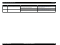
No
Error/Warning Status
Revision A
Error or
Warning
LED
Illustration
on LCD
Message on LCD
Power
Paper Status
Ink Status
MAINTENANCE COVER
OPEN
CLOSE THE
MAINTENANCE
COVER
Light
Off
Blink
63
Maintenance Cartridge Cover Open Warning
Warning
64
Maintenance Cartridge Low
Warning
--
MAINTENANCE CARTRIDGE
IS NEARLY FULL
Light
Off
Blink
65
Printing
--
--
PRINTING
Blink
Off
Off
66
Analyzing
--
--
READY
Blink
Off
Off
Light
Light
Light
67
Printable (Idling)
PRODUCT DESCRIPTION
--
--
READY
Operation Panel
PHOTO_BLACK
34
CHAPTER
2
OPERATING PRINCIPLES
EPSON Stylus Pro 3800/3800C/3850
Revision A
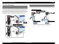
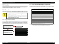
2.1 Overview
OPERATING PRINCIPLES OVERVIEW
2.5 Carriage Mechanism
Explains how to move the Carriage Unit.
2.6 Paper Feed Mechanism
Explains how paper is fed and
transported.
<Main Components>
• CR Motor
• CR Scale
• Timing Belt
• CR Encoder
<Main Components>
• PF Motor
• ASF
• PE Sensor
• Paper Eject Tray
2.2 Print Mechanism
Describes basic specifications of the print
mechanism (print head).
<Main Component>
• Print Head
2.4 Cleaning Mechanism
Explains how the print head is cleaned.
2.3 Ink Supply Mechanism
Explains how the ink is supplied from the
cartridges to the print mechanism.
<Main Component>
• Pump Cap Unit
<Main Components>
• Ink Cartridge
• Ink Cartridge Holder
• Damper
• Pressure Pump
• Ink change system
OPERATING PRINCIPLES
Overview
36
EPSON Stylus Pro 3800/3800C/3850
Revision A
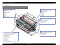
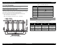
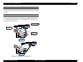
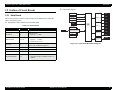
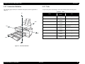
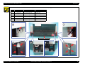
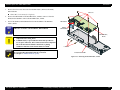
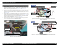
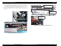
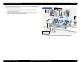
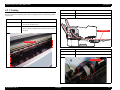
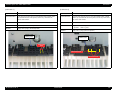
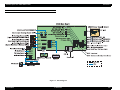
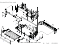
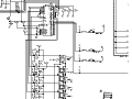
MAIN COMPONENT
Electric Circuit Boards
Table 2-1. List of Electric Circuit Boards
Fig.
Name
1
Function
Communications with host computer
Receive data processing
Engine control
1
Main board (C635 MAIN)
Saves compensation values and various counter
information.
Generates power voltages used by the logic circuits
from 42 V supplied from the power supply board.
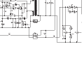
2
Power supply board
(C635 PSB/PSE)
Generates power system power voltage 42 V from
the AC power supply
2
Printer operations, various settings
3
Panel board (C635 PNL)
the LCD.
3
Indicates printer status by the LED.
4
Sub board (C635 SUB)
OPERATING PRINCIPLES
4
Shows printer status and various setting values on
Relays connections between the main board and the
following parts:
PG sensor
Ink mark sensor
PW sensor
Ink change sensor
CR encoder
Ink change motor
Figure 2-1. Layout of Electric Circuit Boards
Overview
37
EPSON Stylus Pro 3800/3800C/3850
Revision A
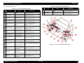
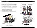
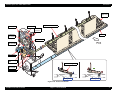
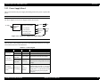
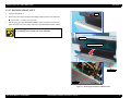
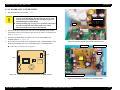
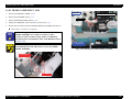
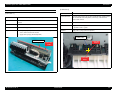
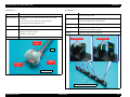
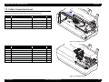
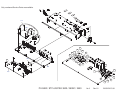
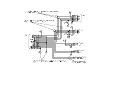
Motors/Solenoid
1
Table 2-2. List of Motors/Solenoid
Fig.
2
Driven Parts
Name
Specifications
Release roller
1
Release motor
3
Type: DC motor
Voltage:42 VDC ± 5 %
9
PF roller
Paper eject roller A
2
PF motor
Paper eject roller B
8
4
Type: DC motor
Voltage:42 VDC ± 5 %
Ink cover unlock mechanism
3
Ink cover unlock solenoid
7
Type: DC solenoid
Voltage:42 VDC ± 5 %
6
Pressure pump
4
Pressure pump motor
5
Ink change motor
6
Pump motor
5
Type: DC motor
Voltage:42 VDC ± 5 %
Ink change system
Figure 2-2. Layout of Motors/Solenoid
Type: DC motor
Voltage:42 VDC ± 5 %
Pump cap unit
Type: 4-phase 48-pole PM stepping motor
Voltage:42 VDC ± 5 %
Carriage unit
7
CR motor
Type: DC motor
Voltage:42 VDC ± 5 %
Platen gap mechanism
8
APG motor
9
ASF motor
Type: 4-phase 96-pole PM stepping motor
Voltage:42 VDC ± 5 %
ASF unit
OPERATING PRINCIPLES
Type: 4-phase 96-pole PM stepping motor
Voltage:42 VDC ± 5 %
Overview
38
EPSON Stylus Pro 3800/3800C/3850
Revision A
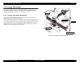
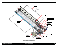
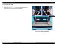
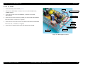
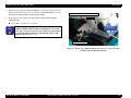
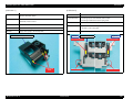
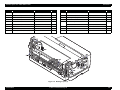
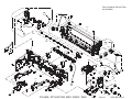
Sensors/Encoders/CSIC
Table 2-3. List of Sensors/Encoders/CSIC
Fig.
Table 2-3. List of Sensors/Encoders/CSIC
Fig.
Name
Function
Detects the ASF origin
position.
Specifications
Type: Transmissive photo interrupter
Voltage: 3.3 VDC ± 5 %
1
ASF phase sensor
2
Release sensor
Detects an open/closed
Type: Transmissive photo interrupter
state of the release roller. Voltage: 3.3 VDC ± 5 %
3
PF encoder
Reads the PF scale.
Type: Linear encoder (180LPI)
Voltage: 3.3 VDC ± 5 %
4
Ink cover sensor
Detects an open/closed
state of the ink cover.
Type: Mechanical contact
Voltage: 3.3 VDC ± 5 %
5
Pressure pump home
sensor
Detects the home
position of the pressure
pump.
Type: Mechanical Contact
Voltage: 3.3 VDC ± 5 %
6
Pressure sensor
Detects the state of
pressurization by the
pressure pump.
Type: Reflective photo interrupter
Voltage: 3.3 VDC ± 5 %,
Comparator input
7
Board paper tray open Detects the position of
sensor
the board paper tray.
8
Ink cartridge sensor
CSIC that stores ink
cartridge information
Type: CSIC
Voltage: 3.3 VDC ± 5 %
PG origin sensor
Detects the origin
position of the platen
gap.
Type: Transmissive photo interrupter
Voltage: 3.3 VDC ± 5 %
Ink change sensor
Detects the state of the
black ink switch lever.
Type: Mechanical contact
Voltage: 3.3 VDC ± 5 %
9
v
10
15
PE sensor
16
CR encoder
2
Ink mark sensor
Detects an open/closed
Maintenance cartridge
state of the maintenance
cover sensor
cartridge cover.
13
PW sensor
14
CSIC that stores
Maintenance cartridge
maintenance cartridge
sensor
information.
Specifications
Type: Transmissive photo interrupter
Voltage: 3.3 VDC ± 5 %
Reads the CR scale.
Type: Linear Encoder (180LPI)
Voltage: 3.3 VDC ± 5 %
1
16
4
5
Type: Mechanical Contact
Voltage: 3.3 VDC ± 5 %
15
6
7
14
8
9
10
Type: Diffuse reflective photo interrupter
Auto Uni-D adjustment
Voltage: 3.3 VDC ± 5 %, LED: 5 V
Auto nozzle check
12
Function
Detects a rear edge of
paper.
3
Auto Bi-D adjustment
11
Name
13
11
12
Figure 2-3. Layout of Sensors/Encoders/CSIC
Type: Mechanical contact
Voltage: 3.3 VDC ± 5 %
Paper leading edge
Type: Reflective photo interrupter
detection
Voltage: 3.3 VDC ± 5 %, LED: 3.3 V
Paper width detection
OPERATING PRINCIPLES
Type: CSIC
Voltage: 3.3 VDC ± 5 %
Overview
39
EPSON Stylus Pro 3800/3800C/3850
Revision A
2.2 Print Mechanism
Table 2-4. Nozzle Rows and Colors
Nozzle Row
Color
A
Magenta
B
Cyan
This section explains the basic specifications of the print head.
NOZZLE CONFIGURATION AND COLORS
Photo Black
C
This printer is equipped with an MACH print head, which employs 180 nozzles per
color. The printer ejects nine different colors of ink through the eight rows of nozzles.
One of the rows is shared by Photo Black and Matte Black inks.
The nozzle configuration as seen from behind the print head is shown below.
Matt Black
D
Yellow
E
Light Light Black
F
Light Black
Printing method: On-demand ink-jet
G
Light Cyan
Nozzle configuration: 180 nozzles x 8 rows = 1440 nozzles
H
Light Magenta
Paper Feed Direction
DRIVE WAVEFORMS
The following four drive waveforms are used to create four print modes.
Table 2-5. Print Modes (Drive Waveforms)
Waveform
Name
Drive Frequency
(kHz)
Print Resolution
(dpi)
CR Speed
(cps)
VSD1
10.08
360 x 360
280
VSD1
10.08
720 x 360
720 x 720
280
VSD2
10.08
1440 x 720
280
VSD3
20.16
2880 x 1440
280
Carriage Moving Direction
Figure 2-4. Nozzle Configuration
OPERATING PRINCIPLES
Print Mechanism
40
EPSON Stylus Pro 3800/3800C/3850
Revision A
2.3.2 Ink Pressurizing Mechanism
2.3 Ink Supply Mechanism
This printer employs an ink pressurizing mechanism to stably supply ink in the ink
cartridge (ink pack) to the print head. This ink pressurizing mechanism consists of a
pressure pump unit installed in an ink supply mechanism and tightly-sealed ink
cartridges. Air pumped into the tightly-sealed ink cartridge from the pressure pump
unit squashes the ink pack in the cartridge, causing the ink inside the pack to be
transferred to the print head.
2.3.1 Ink Flow Path
The ink flow path is shown below.
Ink Selector
+
Dumper
Ink Cartridge
To Print Head
Air flow path
Ink flow path
Ink Cartridge
Pressure Pump
Pressure Sensor Unit
Figure 2-6. Ink Pressurizing Mechanism
Print Head
Figure 2-5. Ink Flow Path
OPERATING PRINCIPLES
Ink Supply Mechanism
41
EPSON Stylus Pro 3800/3800C/3850
Revision A
2.3.2.1 Pressure Pump Unit Mechanism
Applying pressure
Accordion unit/Pressure pump motor/Pressure pump home sensor
The accordion unit intakes air and applies pressure by the rotating drive of the pressure
pump motor, and pumps air into the ink cartridges. The pressure pump home sensor
detects the position of the accordion unit.
Clutch
Valve
CW rotation of the
clutch closes the valve
and applies pressure to
send air toward the ink
cartridges.
Pressure pump motor
Reducing pressure
Combination Gear, 18, 39
CW rotation
CCW rotation of the clutch opens
the valve and reduces pressure.
When the air pressure reaches
the predetermined level, the
valve opens as the pressure
overcomes the tension of the
spring that presses the valve.
CCW rotation
Applying
pressure
Reducing
pressure
Spur Gear, 24.5
Spur Gear, 22
Accordion Unit
Clutch
Pressure Pump
Home Sensor
Combination Gear 18, 3.9
Regulator
Clutch
Figure 2-7. Drive Transmission Path
Spur Gear, 24.5
Pressure sensor unit
Regulator
A reflective photo sensor, which turns on when the air pressure reaches the
predetermined level, controls the amount of pressure. When the air pressure reaches
the predetermined level, film on the air damper expands and activates the reflective
plate causing the sensor to receive light, and the pressurizing state is detected.
Accordion Unit
Spur Gear, 22
Pressure
Pump Motor
Regulator
Stops applying pressure when the power is off or during stand-by. Activated by the
pressure pump motor through the clutch. The regulator opens the valve to reduce
pressure.
Sensor
Air Damper
Film
Pressure Sensor Unit
Figure 2-8. Pressure Pump Unit
OPERATING PRINCIPLES
Ink Supply Mechanism
42
EPSON Stylus Pro 3800/3800C/3850
Revision A
2.3.3 Ink Change System
This printer has automatic ink change system that switches black ink between Photo
Black and Matte Black. The cartridge holder of this printer keeps both Photo Black and
Matte Black ink cartridges. Each of the black ink cartridges has its own ink supply tube
connected to their respective damper. Both black inks are supplied into the damper, and
one of them is supplied to the print head at one time by means of the ink selector that
changes the ink flow path.
Ink change system consists of an ink change motor, selection cam, selection lever, and
ink change sensor. The following describes the mechanism.
1.
Drive of the ink change motor rotates the selection cam.
Ink change sensor detects the rotation angle of the cam.
2.
The selection lever moves as the selection cam rotates.
3.
The protruded end of the selection lever pushes the selection pin, and the pin
changes the black ink flow path inside the damper.
Ink Change Motor
Changing to Matte Black
Changing to Photo Black
Selection
Cam
Selection
Lever
Selection pin
Pressure of
Selection
Lever
Ink Change Sensor
Matt Black
Photo Black
Selection Cam
Matte Black
Selection Lever
Photo Black
Figure 2-10. Changing Black Ink Path
Figure 2-9. Ink Change System
OPERATING PRINCIPLES
Ink Path
Ink Supply Mechanism
43
EPSON Stylus Pro 3800/3800C/3850
Revision A
Cap Unit/Carriage Lock
2.4 Cleaning Mechanism
The pump motor moves the cap unit up and down. The cap unit goes up to seal the
print head during cleaning and stand-by. Carriage lock operates in synchronization
with the cap unit. When the carriage unit moves to the home position, carriage lock
moves up together with the cap unit and lock the carriage unit.
The cleaning mechanism consists of a pump cap unit and a waste ink pads
(maintenance cartridge).
Pump Motor
The pump motor drives the cap unit, pump, head cleaner, and carriage lock. The table
below shows the operation of each mechanism depending on the rotational direction of
the pump motor.
Table 2-6. Pump Motor Functions
Mechanism
CCW *
CW *
Open (Uncapping)
Close (Capping)
Pump release
Pump suction
Head Cleaner
Wiper reset
(back to the home)
Wiper set
(moves to the wiping position)
Carriage Lock
Unlock
Lock
Cap Unit
Pump
Note *:
Cap Unit
Carriage Lock
Cap unit moves up
(capped, locked)
Cap unit moves down
(uncapped, unlocked)
Spur Gear, 13
The rotation direction as seen from the top of the unit.
Pinion Gear
(Pump Motor)
Pump Motor
Combination Gear, 15.5, 9.5
Spur Gear, 26.5
Spur Gear, 13
Pump
Spur Gear, 21.5
Spur Gear, 21.5
Intermittent Gear, 21.5
Combination Gear, 16, 11.5
Spur Gear, 26.5
Intermittent
Gear, 21.5
Combination Gear, 15.5, 9.5
Cap Unit
Carriage Lock
Figure 2-12. Cap Unit/Carriage Lock Mechanism
Combination Gear, 13.5, 10
Head Cleaner
Figure 2-11. Drive Transmission Path
OPERATING PRINCIPLES
Cleaning Mechanism
44
EPSON Stylus Pro 3800/3800C/3850
Revision A
Pump Unit
Head Cleaner
The ink is absorbed from the head nozzles. The sucked waste ink is conveyed to the
waste ink pad through the tube.
The CW rotation of the pump motor rotates the conveyance roller. The roller rotates
pressing the tube to convey the waste ink from the cap unit to the waste ink pad.
The CCW rotation of the pump motor moves the conveyance roller away from the
pressing position.
The head cleaner wipes off ink, dirt or the like from the surface of the head nozzles.
The CW rotation of the pump motor moves the head cleaner to the wiping position.
Head Cleaner
Head Nozzle
Combination
Gear, 13.5, 10
Intermittent Gear, 21.5
Combination
Gear, 13.5, 10
Combination
Gear, 16, 11.5
Spur Gear,13
Conveyance Roller
Spur Gear, 26.5
To Waste Ink Pad
Figure 2-13. Pump Unit Mechanism
Combination
Gear,15.5, 9.5
Spur Gear, 21.5
Pinion Gear
(Pump Motor)
Figure 2-14. Head Cleaner Mechanism
OPERATING PRINCIPLES
Cleaning Mechanism
45
EPSON Stylus Pro 3800/3800C/3850
Revision A
2.5 Carriage Mechanism
The carriage mechanism consists of a carriage movement mechanism, platen gap
adjustment mechanism, and carriage lock mechanism. For explanation about the
carriage lock mechanism, refer to Cap Unit/Carriage Lock (p.44).
CR Scale
CR Scale
2.5.1 Carriage Movement Mechanism
CR Encoder
Carriage movement mechanism consists of a carriage unit, CR motor, timing belt,
carriage guide shaft, CR scale, and CR encoder.
Rotational drive of the CR motor is transmitted to the carriage unit through the timing
belt, and the carriage unit moves left and right along the carriage guide shaft. The CR
encoder installed on the back of the carriage unit reads the jagged surface of the CR
scale and sends the read value to the main board. Position and moving speed of the
carriage unit are controlled based on the read value.
CR Timing Belt
CR Motor
Carriage Unit
Carriage Guide Shaft
Figure 2-15. Carriage Movement Mechanism
OPERATING PRINCIPLES
Carriage Mechanism
46
EPSON Stylus Pro 3800/3800C/3850
Revision A
Table 2-7. PG Positions in Operations
2.5.2 Platen Gap Adjustment Mechanism
Platen gap adjustment mechanism consists of an APG motor, carriage unit, and PG sensor.
The carriage unit is equipped with two carriages; main carriage that moves horizontally to
the carriage guide shaft, and the sub carriage that moves vertically to the main carriage.
When the carriage unit moves to the PG adjustment position and the APG motor starts to
rotate, the oval cam turns to move the sub carriage vertically and change the platen gap
amount. Light-shielding plate with a cutout is installed at the end of the shaft to which the
cam is attached, and moves together with the cam. A transmissive photo interrupter sensor
(PG sensor) detects the cutout, determines the detected position as the origin, and changes
the platen gap according to the number of pulses from the origin.
Operation
PG
Detecting paper width
(ASF feeding, Rear/Front manual feeding)
Detecting paper width
(ASF feeding after receiving data)
Switch PG according to the print setting.
Starts printing
Switch PG according to the print setting.
At power OFF
1.2
PG Sensor
APG Motor
3.5
Main Carriage
Combination Gear, 20, 34.4
APG Motor
Combination Gear, 13.6, 31.2
Lightshielding
Plate
Spur Gear, 29.6
Cutout
Combination
Gear,20, 34.4
Cam
Spur Gear, 34.4
Combination
Gear,13.6, 31.2
PG Shaft
Cam
Sub Carriage
Spur Gear, 34.4
Spur Gear, 29.6
Cam
Sub Carriage
Figure 2-16. Drive Transmission Path
The relation between the printer status and the platen gap amount is described below.
Table 2-7. PG Positions in Operations
Operation
PG
At power ON
1.2
Cleaning starts
1.5
Capping
Board paper tray is open
OPERATING PRINCIPLES
Narrow
Wide
Capping is done in the current PG.
Figure 2-17. Platen Gap Adjustment Mechanism
3.5
Carriage Mechanism
47
EPSON Stylus Pro 3800/3800C/3850
Revision A
2.6 Paper Feed Mechanism
2.6.1 Paper Feed Path
The printer provides two manual paper feed paths in addition to the ASF to support
thicker paper.
Paper Feeding
Thickness
Type
1
ASF (Auto Sheet Feeder)
0.08 to 0.27 mm
See 1.3.3 Paper Support (p.15)
2
Rear Manual Bypass
0.29 to 0.5 mm
Fine Art Paper
3
Front Manual Bypass
1.2 to 1.5 mm
Heavy paper like cardboard
3
The following figures show the paper feed paths.
Figure 2-19. Paper Path of Front Manual Bypass
1
2
Figure 2-18. Paper Path of ASF & Rear Manual Bypass
OPERATING PRINCIPLES
Paper Feed Mechanism
48
EPSON Stylus Pro 3800/3800C/3850
Revision A
2-2.
2.6.2 Paper Loading Mechanism
ASF (AUTO SHEET FEEDER)
The LD roller shaft rotates to release the hopper actuating the cam that
presses the hopper, and the hopper moves up by the tension of the spring.
Hopper
The ASF, whose driving source is an ASF motor, consists of a LD roller, LD roller
shaft, ASF sensor, hopper, and paper anti-slip tab. The cams on both ends of the LD
roller shaft activate the hopper and the paper anti-slip tab. The ASF sensor (photo
interrupter sensor) controls the rotational position of the LD roller shaft by detecting
the light-shielding plate installed on the shaft. Paper loading operation from the ASF is
described below:
1.
Start of the paper loading operation
The ASF motor moves to rotate the LD roller shaft.
2.
Feeding paper to the paper loading position
2-1.
Hopper Actuating Cam
The LD roller shaft rotates to release the lever that presses the paper antislip tab, and the tabs go down.
LD Roller
Standby
Raising
Figure 2-21. Raising the Hopper
ASF Motor
Hopper
3.
Picking-up paper
The LD roller shaft rotates to feed a single sheet of paper into the printer with a LD
roller.
Paper
Hopper
LD Roller
Lever
LD Roller Shaft
Separation Pad
Paper Anti-slipTab
Retard Roller
Figure 2-20. Lowering the Paper Anti-slip Tab
OPERATING PRINCIPLES
Figure 2-22. Picking-up Paper
Paper Feed Mechanism
49
EPSON Stylus Pro 3800/3800C/3850
Revision A
4.
Pressing the hopper
The hopper cam on the LD roller shaft presses the hopper and remaining paper on
the tray is moved away from the feeding position.
5.
Moving the paper anti-slip tabs upward
The LD roller shaft rotates to actuate the lever on the shaft and move the paper
anti-slip tabs upward. The tabs prevent the paper from slipping into the paper
feeding section.
6.
Transporting paper in the printer
Paper fed into the printer is transported by the PF roller.
7.
8.
Standing-by
The hopper returns to the stand-by position and ends the paper loading operation.
Position Detection Section
ASF Sensor
Combination
Gear, 58.22
Releasing the back end of paper
When the hopper actuating cam presses the hopper further in synchronization with
the rotation of the LD roller, left and right paper guides that regulate the paper
width are extended releasing the back end of paper.
Hopper
Hopper
ASF Motor
groove Hopper
Actuating
Cam
Paper Anti-slip Tab
LD Roller Shaft
LD Roller
Retard Roller
Spur Gear,
Shaft, LD
Figure 2-24. ASF Drive Mechanism
ASF Motor
LD Roller Shaft
Paper Holding State
Combination Gear, 58,22
Paper Releasing State
Figure 2-23. Releasing the Back End of Paper
Spur Gear, Shaft, LD
LD Roller Shaft
LD Roller
Paper Anti-slip Tab
Hopper Assy
Figure 2-25. ASF Drive Transmission Path
OPERATING PRINCIPLES
Paper Feed Mechanism
50
EPSON Stylus Pro 3800/3800C/3850
Revision A
REAR MANUAL BYPASS
When the prescribed time has passed since a paper was supplied from the feeder on the
rear of the printer and the PE sensor detected the paper, the PF roller starts to transport
the paper.
FRONT MANUAL BYPASS
The status of the board paper tray that is used for the front manual feeding is detected
by the leaf switch. The leaf switch is moved by the Board Paper Guide Cam which
moves together with the board paper tray, and according to the switch position, the
board paper tray status is detected.
Board Paper Tray
Leaf Switch
Board Paper
Guide Cam
Tray Closed
Tray Open
Figure 2-26. Board Paper Tray Open Sensor
OPERATING PRINCIPLES
Paper Feed Mechanism
51
EPSON Stylus Pro 3800/3800C/3850
Revision A
2.6.3 Paper Feed Mechanism
The paper feed mechanism mainly consists of a Release mechanism, the PF Motor, and
the feed rollers.
Release Motor
Combination Gear, 9.6, 22
RELEASE MECHANISM
Release mechanism consists of a release unit (including a release motor, release sensor,
and combination gear), paper guide upper assy that presses papers, and paper guide
release shaft that activates the paper guide upper assy.
Rotational drive of the release motor activates the paper guide release shaft through the
combination gear. When the release lever of the paper guide release shaft presses down
the back end of the paper guide upper assy, the paper guide upper assy separates from
the PF roller. When the release motor rotates reversely, the paper guide upper assy
makes contact with the PF roller. The release sensor installed in the release unit and the
light-shielding plate detects the contact condition between the paper guide upper assy
and the PF roller.
Spur Gear, 22
Combination Gear, 8, 22
Combination Gear, 8, 22
Combination Gear, 8, 22.986
Spur Gear, 20.4
Combination Gear, 22, 32.4
Light-shielding Plate
Spur Gear, 22.B
Paper Guide Release Shaft
Paper Guide Upper Assy
Figure 2-27. Drive Transmission Path
OPERATING PRINCIPLES
Paper Feed Mechanism
52
EPSON Stylus Pro 3800/3800C/3850
Revision A
Paper Guide
Upper Assy
Spur Gear, 22
Paper Guide Release Shaft
Release Motor
Combination
Gear, 8, 22
PF Roller
Combination
Gear, 9.6, 22
Spur Gear, 20.4
Combination
Gear, 8, 22.986
Release Sensor
Light-shielding
Plate
Paper Guide Upper Assy
Combination
Gear, 22, 32.4
Spur Gear, 22,B
Holding status
Releasing status
Figure 2-28. Release Mechanism
OPERATING PRINCIPLES
Paper Feed Mechanism
53
EPSON Stylus Pro 3800/3800C/3850
Revision A
PAPER FEED MECHANISM
Paper feed mechanism consists of a PF motor, PF scale, PF encoder, PF roller, front
and rear paper eject rollers, and star wheels. The mechanism transports papers fed from
the feeders and ejects them from the front of the printer.
PF Motor
PF Timing Belt
Combination Gear, PF, Drive
Spur Gear, 31.5
PF Motor
Spur Gear, 68
Front Paper Eject Roller
Spur Gear, 14.4
Rear Paper Eject Roller
Figure 2-29. Drive Transmission Path
OPERATING PRINCIPLES
Paper Feed Mechanism
54
EPSON Stylus Pro 3800/3800C/3850
Revision A
Frame, EJ Assy
Paper
Star Wheel
Front Paper Eject Roller
Rear Paper Eject Roller
PF Roller
Spur Gear, 14.4
PF Encoder
Spur Gear, 68
Spur Gear, 31.5
PF Motor
PF Scale
PF Timing Belt
Combination Gear, PF, Drive
Figure 2-30. Paper Feed Mechanism
OPERATING PRINCIPLES
Paper Feed Mechanism
55
EPSON Stylus Pro 3800/3800C/3850
Revision A
2.7 Ink Mark Sensor
This printer is equipped with the ink mark sensor functioning as multi sensors.
The sensor, located on the bottom of the carriage unit, is a diffuse reflective
photointerruptor that is comprised of a light emitting part (white LED) and a light
receiving part (photoreceiver). The white LED emits light against the paper or
dedicated print pattern printed on paper and the photoreceiver reads the reflected light.
According to the reflected light read by the receiver, the printer calculates correction
values to perform proper corrective actions.
The Ink mark sensor is used for the following adjustments.
Auto Bi-D Adjustment
The sensor scans predetermined patterns printed for the adjustment and detects the
highest density pattern among them. According to the detected result, the printer
calculates Bi-D correction values automatically.
Auto Uni-D Adjustment
The sensor scans predetermined patterns printed for the adjustment and detects the
highest density pattern among them. According to the detected result, the printer
calculates Uni-D correction values automatically.
Auto Nozzle Check
The sensor scans a nozzle check pattern. The pattern is printed with the all nozzles and
each nozzle prints one block. If there is a clogged nozzle, the corresponding block will
not be printed and detected by the sensor, and a head cleaning is performed
automatically.
OPERATING PRINCIPLES
Ink Mark Sensor
56
EPSON Stylus Pro 3800/3800C/3850
Revision A
2.8 Other Mechanisms
MAINTENANCE CARTRIDGE COVER OPEN DETECTION
INK COVER OPEN-CLOSE MECHANISM
To keep the maintenance cartridge from being removed during printing, a switch
sensor detects opening/closing state of the cover that stores the maintenance cartridge.
To keep the ink cartridges from being removed during printing, opening/closing of the
ink cover is electrically regulated. Opening/closing of the cover is controlled by the
lock mechanism that takes advantage of an electromagnetic solenoid, and the cover can
only be opened by means of the operation panel. When the operation to open the cover
is performed, the solenoid is energized and the lock is released. The solenoid unit is
equipped with a switch sensor that detects opening/closing state of the cover.
Maintenance Cartridge Cover Sensor
Maintenance Cartridge Cover
Ink Cover Closed
Solenoid
Ink Cover
Cover Closed
Solenoid Unit
Ink Cover Sensor
Cover Open
Figure 2-32. Operation of Maintenance Cartridge Cover
Ink Cover Open
Figure 2-31. Ink Holder Cover Open/Close Mechanism
OPERATING PRINCIPLES
Other Mechanisms
57
EPSON Stylus Pro 3800/3800C/3850
Revision A
Circuit block diagram
2.9 Outline of Circuit Boards
DDR-SDRAM
(IC3)
2.9.1 Main Board
DDR-SDRAM
(IC19)
USB I/F 2.0
FlashROM
Flash ROM
(IC1)
Function
IC15
Customized ASIC
IC4
Program storage
• Capacity:
16Mbit
CN102
Custom
ASIC
E01A68C
(IC15)
Pressurizing Pump Motor
A6628 (IC7)
CN58
Ethenet 10/100BASE-TX
BCM5980A2KFBG(IC10)
SDRAM
(IC5)
SDRAM
(IC8)
DDR-SDRAM
IC3/IC19
RTC9824
IC9
RTC complex circuit
(Reset, timer, EEPROM complex IC)
E09A54RA
IC11
Printer driver
A6628SEDT
IC7/IC13
Motor driver
A6627STPT
IC6
Motor driver
BCM5980A2KFBG
IC10
Ethernet 10/100BASE-TX circuit
• Flash ROM (32Mbit), SDRAM (64Mbit x 2)
installed
CN57
Release Motor
Pump Motor
CN41
Network
Various buffers, work areas
• Capacity:
256Mbit
• Number of pieces: two
OPERATING PRINCIPLES
Ink Change Motor
CN45
CN67
Table 2-8. Main Elements
E01A68CB
ASF Motor
CN44
RTC9824
(IC9)
Explanation of main elements on C635 MAIN Board
Location
CN43
A6628 (IC13)
Flash ROM
(IC4)
This section provides a summary of the main board (C653MAIN) that controls the
whole of the printer system.
Model Number
CN40
CR Motor
A6627 (IC6)
PF Motor
CN41
APG Motor
Custom
ASIC
E09A54RA
(IC11㧕
CN69/70/
71/72
Print Head
Figure 2-33. C635 MAIN Board Block Diagram
Outline of Circuit Boards
58
EPSON Stylus Pro 3800/3800C/3850
Revision A
2.9.2 Power Supply Board
This section describes the power supply board that generates the power to operate this
printer.
CIRCUIT BLOCK DIAGRAM
The block diagram of C635 Power Supply board is shown below.
Pseudo-resonance type
separately-excited flyback
Input Filter
(Rush current
prevention
circuit
AC input
1. OCP function
2. OVP function
3. Secondary power
switch function
+42V/0.7A
5VOVP
ESAVE
PSC
DC
output
Control
signal
input
Figure 2-34. C635 Power Supply Board Block Diagram
CONTROL SIGNALS
There are three control signals between the C635 MAIN Board and the Power Supply
Circuit Board as shown in the table below.
Table 2-9. Control Signals
Signal Name
PS Control
Signal (PSC)
Function
Output
Remarks
Power ON
39.9 to 44.1 V
The PS unit outputs the rated voltage.
Power OFF
3V or less
The PS unit is instantly shut off.
Normal
Operation
39.9 to 44.1 V
The PS unit outputs the rated voltage.
15V Typ.
It takes less than 500 msec to recover
from the power saving mode to the rated
voltage.
0V
(Power is
shutoff)
The power is shut off when the OVP
terminal voltage exceeds 7 V. To recover
from the status, lower the OVP terminal
voltage below 7 V, and reboot the printer
after reinserting the power plug into a
receptacle.
Energy Save
Signal (ESAVE) Power Saving
Operation
Overvoltage
Detection of
Detection Signal
overvoltage
(OVP)
OPERATING PRINCIPLES
Outline of Circuit Boards
59
EPSON Stylus Pro 3800/3800C/3850
Revision A
2.10 Colorimetric Calibration (Color ID) Overview
This printer employs “Colorimetric Calibration (Color ID)” to correct unit-to-unit
variations in color.
Colorimetric Calibration (Color ID) corrects not only the weight of ink droplets which
differs depending on the individual characteristics of print head but also variable
factors such as drive circuit and voltage. This enables a higher-accuracy calibration.
Main Unit
Print Head
Main Board
Power Supply
Board
OVERVIEW
1.
Printing/ Measuring the color of a correction pattern
A correction pattern printed by a completed product is used for the calibration.
A calibrator is used to perform the color measurement of the printed pattern.
2.
Writing the correction value
Correction values are automatically calculated based on the result of the color
measurement and stored in the NVRAM on the main board.
3.
Reflecting the correction value
Every time the printer makes a print, the printer driver reads out the correction
values from the NVRAM. Each ink droplet weight and the number of ink droplets
for each dot are corrected according to the information.
Variation of elements on
the print head control
circuit
Individual characteristic
of print head
Drive Control
Circuit for
Print Head
Variation in
voltage
applied to
print head
Colorimetric Calibration
(Color ID)
Correction of the number of ink droplets
Correction of
ink droplet weight
Printout
Figure 2-35. Colorimetric Calibration (Color ID)
OPERATING PRINCIPLES
Colorimetric Calibration (Color ID) Overview
60
CHAPTER
3
TROUBLE SHOOTING
EPSON Stylus Pro 3800/3800C/3850
Revision A
3.1 Overview
W A R N IN G
When handling the lithium battery used for backup of the RTC on
the main board, strictly follow the safety instructions given in
“4.1.1 Precautions” (p86).
C A U T IO N
This section explains the basic procedure for troubleshooting problems on the printer
quickly and efficiently.
3.1.1 Preliminary Check
Make sure to verify or perform the following basic items whenever servicing the
printer.
1.
There is no foreign material which interferes with the proper operation of the
printer.
2.
Print the status sheet, and check the information printed on the sheet to find out
possible causes of the error; if the main units have reached their end of life, or if
there is something wrong with the user-defined panel settings.
3.
Both outside and inside of the printer are free of significant dirt. Clean it if
significant dirt is observed.
4.
None of the parts or components of the printer are missing, chipped or damaged.
5.
All of the harnesses are free of damages and properly connected to their
connectors.
6.
The cams and gears in the printer mechanism are engaged correctly showing no
signs of wear.
7.
When smudges appear on printed pages, clean the rubber rollers in the printer
mechanism if it solves the problem.
8.
The rubber rollers in the printer mechanism are engaged correctly showing no
signs of wear.
9.
Initialize the NVRAM on the C635 main board (reset the user-defined panel
settings to their factory default) if necessary.
Execute the DEFAULT PANEL in the Maintenance mode.
TROUBLE SHOOTING
Before disassembling/reassembling the printer, be sure to turn
the power OFF, confirm the panel display disappears, and
unplug the power code.
Be sure to use the specified tools for maintenance/repair.
To maintain the product’s quality, be sure to use the specified
lubricant and adhesive.
Be sure to perform the adjustments as required.
3.1.2 Troubleshooting Procedure
Follow the flowchart given below to troubleshoot problems efficiently.
Occurrence of Troubles
Error message is
displayed on the LCD
(Page 63)
Warning message is
displayed
(Page 68)
Overview
Print Quality Troubles
(Page 82)
Error message is
displayed
(Page 66)
Service Call message is
displayed
(Page 74)
62
EPSON Stylus Pro 3800/3800C/3850
Revision A
Table 3-1. List of Panel Messages
3.2 List of Panel Messages
The printer runs diagnostic checks on itself according to various conditions detected by
the mounted sensors. If an error condition is detected as a result of the self-diagnosis,
the printer displays the corresponding error message on its LCD panel.
The error messages are shown on the following list.
Category
Table 3-1. List of Panel Messages
Category
Warning
Error
Message on LCD
MAINTENANCE REQUEST
XXXX
INK LOW
MAINTENANCE CARTRIDGE
IS NEARLY FULL
SERVICE CALL ERROR
NNNN
PLEASE CONTACT TO THE
REPAIR CENTER
PRINTER ERROR
RESTART THE PRINTER
CARRIAGE LOCKED
RELEASE THE CARRIAGE
LOCK
PAPER JAM
CLEAR JAMMED PAPER
SEE PRINTER GUIDE
FOR INSTRUCTIONS
NO MAINTENANCE CART.
INSTALL THE
MAINTENANCE
CARTRIDGE.
MAINTENANCE COVER
OPEN
CLOSE THE
MAINTENANCE COVER
PAPER FEED ERROR
REMOVE PAPER
AND LOAD PAPER
CORRECTLY
TROUBLE SHOOTING
Ref.
Page
Description
Maintenance Call Warning
p66
Ink level is low.
The maintenance cartridge is close
to its full status.
A fatal error has occurred.
(Service Call No. is displayed.)
p66
p66
p68
A fatal error has occurred.
(Rebooting the printer is required))
A fatal error has occurred.
(The carriage is locked)
p68
Error
p68
A paper jam has occurred.
(Fatal error)
p68
No maintenance cartridge is
recognized.
A maintenance cartridge CSIC read/
write error has occurred.
The maintenance cartridge cover is
open.
p68
p68
p68
Failed to feed paper into the printer.
Message on LCD
PAPER FEED ERROR
LOAD PAPER CORRECTLY
AND PRESS PAPER/FEED
BUTTON
PAPER JAM
REMOVE PAPER
CANNOT OPEN COVER
IS THERE ANYTHING ON
THE PRINTER?
PRESS THE UP BUTTON
MAINTENANCE
CARTRIDGE NEARLY FULL
REPLACE THE
CARTRIDGE
NOT ENOUGH INK
REPLACE INK CARTRIDGE
WITH A NEW ONE
MAINTENANCE
PLEASE USE GENUINE
EPSON CARTRIDGES
MAINTENANCE
NON-GENUINE CARTRIDGE!
MAY NOT PERFORM AT
OPTIMUM. CONTINUE?
<YES
NO>
MAINTENANCE
THIS MAY VOID EPSON’S
WARRANTY.
DO YOU ACCEPT THIS?
<ACCEPT
DECLINE>
MAINTENANCE
CARTRIDGE
FULL
REPLACE THE
CARTRIDGE
Description
Failed to feed board paper into the
printer.
A paper jam has occurred and failed
to eject the paper.
Failed to open the ink cartridge
cover.
The maintenance cartridge is almost
full (insufficient for the required
job).
Ref.
Page
p69
p69
p69
p69
The ink cartridge is almost empty
(insufficient for the required job).
p69
The maintenance cartridge is not an
EPSON-genuine one.
p69
The maintenance cartridge is not an
EPSON-genuine one.
(Confirmation 1)
p69
The maintenance cartridge is not an
EPSON-genuine one.
(Confirmation 2)
p69
The maintenance cartridge is full.
p69
p68
List of Panel Messages
63
EPSON Stylus Pro 3800/3800C/3850
Revision A
Table 3-1. List of Panel Messages
Category
Error
Message on LCD
FRONT FEED SLOT OPEN
PRESS THE
DOWN
BUTTON
AND REMOVE
PAPER
FRONT FEED SLOT OPEN
CLOSE THE
FRONT MANUAL
FEED SLOT
FRONT FEED SLOT OPEN
LOAD
MEDIA AND
PRESS THE
DOWN BUTTON
FRONT SLOT CLOSED
OPEN THE
FRONT MANUAL
FEED SLOT
FRONT SLOT CLOSED
OPEN THE
FRONT MANUAL
FEED SLOT
NO INK CARTRIDGE
INSTALL INK CARTRIDGE
INK CARTRIDGE ERROR
REPLACE CARTRIDGE
INK CARTRIDGE
PLEASE USE GENUINE
EPSON INK CARTRIDGE
INK CARTRIDGE
NON-GENUINE CARTRIDGE!
MAY NOT PERFORM AT
OPTIMUM. CONTINUE?
<YES
NO>
TROUBLE SHOOTING
Table 3-1. List of Panel Messages
Ref.
Page
Description
Category
A board paper could not be
removed.
p70
The board paper tray was opened in
the middle of printing.
p70
No paper has been loaded on the
board paper tray.
p70
The board paper tray was closed in
the middle of printing.
p70
The board paper tray was closed
when a paper in the tray needs to be
removed.
No ink cartridge is recognized.
Error
p70
p70
An ink cartridge CSIC read/write
error has occurred.
The ink cartridge is not an EPSONgenuine one.
p70
p70
The ink cartridge is not an EPSONgenuine one. (Confirmation 1)
p71
List of Panel Messages
Message on LCD
INK CARTRIDGE
THIS MAY VOID EPSON’S
WARRANTY.
DO YOU ACCEPT THIS?
<ACCEPT
DECLINE>
INK CARTRIDGE
REPLACE INK CARTRIDGE
INK COVER OPEN
CLOSE THE INK COVER
COMMAND ERROR
CHECK DRIVER SETTINGS
PAPER SKEW
PRESS THE
DOWN BUTTON
LOAD PAPER
CORRECTLY
PAPER ERROR
PRESS THE
DOWN BUTTON
LOAD PAPER
CORRECTLY
BORDERLESS ERROR
PRESS THE DOWN BUTTON
LOAD THE CORRECT SIZE
PAPER
PAPER EJECT ERROR
PRESS THE
DOWN BUTTON
AND REMOVE
PAPER
PAPER FEED ERROR
LOAD PAPER
CORRECTLY
PRESS THE
DOWN BUTTON
PAPER REMOVE
REMOVE PAPER
FROM THE REAR
Description
Ref.
Page
The ink cartridge is not an EPSONgenuine one. (Confirmation 2)
p71
The ink cartridge is empty.
The ink cartridge cover was opened.
A command error has occurred.
p71
p71
p71
The loaded paper is skewed.
p71
Failed to detect the paper width.
p71
The paper size is not available for
the borderless printing.
p72
Failed to eject a cut sheet of paper.
p72
A multi-feed was detected and the
papers were ejected automatically
without printing.
p72
Failed to eject paper fed from the
rear manual tray.
p72
64
EPSON Stylus Pro 3800/3800C/3850
Revision A
Table 3-1. List of Panel Messages
Category
Message on LCD
PAPER ERROR
LOAD PAPER
PAPER SIZE ERROR
LOAD THE CORRECT SIZE
PAPER
PAPER SENSOR ERROR
PRESS THE
BUTTON
LOAD DIFFERENT PAPER
PAPER SENSOR ERROR
PRESS THE
BUTTON
LOAD THE CORRECT PAPER
Error
CLEANING ERROR
PRESS THE CANCEL/RESET
BUTTON
CLEANING ERROR
PRESS THE
DOWN BUTTON
AND REMOVE
THICK PAPER
PAPER SETTING ERROR
CHECK PAPER SOURCE IN
THE DRIVER SETTINGS
AND LOAD PAPER
CORRECTLY
TROUBLE SHOOTING
Ref.
Page
Description
No paper is detected.
p72
The size of loaded paper does not
match with the paper size setting.
p72
The ink mark sensor sensitivity
adjustment could not be made.
p72
Failed to determine the adjustment
value based on the result detected
by the ink mark sensor. (could not
determine, or the determined value
fell outside the adjustable range.)
Clogging nozzles are detected by
the nozzle check after running a
head cleaning.
A head cleaning was attempted with
a board paper loaded, or before
printing when the PW sensor was
OFF.
The paper has been loaded in the
tray that is different from the one
specified in the driver setting.
p73
p73
p73
p73
List of Panel Messages
65
EPSON Stylus Pro 3800/3800C/3850
Revision A
3.3 Remedies for Warning Messages
When a Warning error occurs, the printer displays a Warning message instead of “READY” or “PRINTING” messages, however, it does not interfere with printing operation.
REMEDIES
The following tables explains the Warning messages and remedies.
Table 3-2. Remedies for Warning Messages
Message on LCD
Description
Remedy
MAINTENANCE REQUEST
XXXX
See MAINTENANCE Request XXXX on page 67.
INK LOW
The remaining ink is low.
Prepare a new ink cartridge.
MAINTENANCE CARTRIDGE
IS NEARLY FULL
The free space of the maintenance cartridge is low.
Prepare a new maintenance cartridge.
TROUBLE SHOOTING
Remedies for Warning Messages
66
EPSON Stylus Pro 3800/3800C/3850
Revision A
MAINTENANCE REQUEST XXXX
When a Maintenance Request error occurs, the printer displays on the LCD a hexadecimal code of “NNNN” which correspond to the bit numbers assigned to error statuses as shown
in the table below.
Table 3-3. Maintenance Request Errors
Bit assignment (Binary)
NOTE
9
10
11
12
13-15
Cause
Remedy
0
0
0
(NA) (NA)
0
0
(RSVD)
0001
0
1
(NA)
0
(NA) (NA)
0
0
0
(NA) (NA)
0
0
(RSVD)
0002
The CR scan pass counter has reached
the specified value. (ink supply tube
has reached its end of life.)
Replace the tube (INK,SYSTEM,ASSY.) with a new one,
and clear the counter using the Adjustment Program.
0
0
(NA)
1
(NA) (NA)
0
0
0
(NA) (NA)
0
0
(RSVD)
0008
The RTC backup battery becomes
exhausted.
Replace the battery with a new one, and execute RTC
initialization using the Adjustment Program.
0
0
(NA)
0
(NA) (NA)
1
0
0
(NA) (NA)
0
0
(RSVD)
0040
The pump counter has reached the
specified value.
Replace the pump cap unit (PUMP,CAP,ASSY.) with a new
one, and clear the counter using the Adjustment Program.
0
0
(NA)
0
(NA) (NA)
0
1
0
(NA) (NA)
0
0
(RSVD)
0080
The date has not been set.
Execute RTC initialization using the Adjustment Program.
0
0
(NA)
0
(NA) (NA)
0
0
1
(NA) (NA)
0
0
(RSVD)
0100
The RTC backup battery power has
temporarily dropped.
Wait until the power recovers.
0
0
(NA)
0
(NA) (NA)
0
0
0
(NA) (NA)
1
0
(RSVD)
0800
The ink cartridge installation/removal
counter has reached the upper limit.
Replace the waste ink pad (POROUS PAD,TRAY,INK
EJECT) in the cartridge holder with a new one, and clear the
counter using the Adjustment Program.
0
0
(NA)
0
(NA) (NA)
0
0
0
(NA) (NA)
0
1
(RSVD)
1000
The number of drives of the ink
selector has reached the upper limit.
Replace the ink selector (INK,SYSTEM,ASSY.) with a new
one, and clear the counter using the Adjustment Program.
0
0
(NA)
1
(NA) (NA)
0
1
0
(NA) (NA)
0
0
(RSVD)
0088
RTC backup battery has not been set.
Install a battery, and execute RTC initialization using the
Adjustment Program to set date and time.
Holder absorber life
(NA) (NA)
Unassigned
0
Unassigned
(NA)
Unassigned
0
Unassigned
1
Unassigned
8
Ink selector life
7
Battery voltage
6
Date not set
5
Pump cap unit life
4
Battery exhaustion
3
Unassigned
2
Replace the waste ink pads for borderless printing
The counter of waste ink used for
(POROUS PAD,INK WASTE BOX, LEFT/RIGHT) with
printing margins at borderless printing
new ones, and clear the counter using the Adjustment
has reached the specified value.
Program.
Borderless printing absorber
Description
Ex.
1
CR life
0
XXXX
(Hexadecimal)
: Ex): When “Maintenance Request 0088” is displayed.
As “0088” in hexadecimal means “1000 1000” in binary, you can find out the code is assigned to Bit-3 and Bit-7 referring to the above table. In this case, two
errors are occurring simultaneously. (Bit-3: battery exhaustion/ Bit-7: the date and time has not been set.)
TROUBLE SHOOTING
Remedies for Warning Messages
67
EPSON Stylus Pro 3800/3800C/3850
Revision A
3.4 Remedies for Error Messages
The following tables explains the error messages and remedies.
Message on LCD
Description
Remedy
SERVICE CALL ERROR
NNNN
PLEASE CONTACT TO THE
REPAIR CENTER
See 3.5 Remedies for Service Call Error on page 74.
PRINTER ERROR
RESTART THE PRINTER
A firmware bug, or some circuit component(s) on the main board is (are)
damaged.
Turn the printer Off and reboot it after waiting for a while. If a Service Call
error occurs, see 3.5 Remedies for Service Call Error (p74) for further
troubleshooting.
CARRIAGE LOCKED
RELEASE THE CARRIAGE
LOCK
The power is turned On without removing the protective material for the print
head.
Remove the protective material.
PAPER JAM
CLEAR JAMMED PAPER
SEE PRINTER GUIDE
FOR INSTRUCTIONS
A paper jam has occurred.
Remove the jammed paper and load paper correctly.
Paper feeding was physically interrupted.
Check the paper feed path and remove any scrap of paper or foreign matter.
NO MAINTENANCE CART.
INSTALL THE
MAINTENANCE
CARTRIDGE.
No maintenance cartridge has been installed.
Install a maintenance cartridge.
The maintenance cartridge cannot be recognized by the printer.
Remove the maintenance cartridge and reinstall it correctly. If this does not
solve the problem, replace the cartridge with a new one.
The printer cannot read/write data from/to the CSIC of the maintenance
cartridge properly.
Replace the maintenance cartridge with a new one.
MAINTENANCE COVER
OPEN
CLOSE THE
MAINTENANCE COVER
The cover of the maintenance cartridge is open.
Close the maintenance cartridge cover.
The maintenance cartridge cover sensor cannot detect that the cover is closed.
Check the cover. If any damage is observed, replace it with a new one.
The PE sensor detected paper is still in the paper feed path. Torn scrap of paper Check the paper feed path around the PE sensor and remove any scrap of paper
or some foreign matter may exist.
or foreign matter.
Check that the following connectors are connected correctly.
Connector on the maintenance cartridge cover sensor
CN62 on the main board
Replace the maintenance cartridge cover sensor.
See 4.3.6.4 MAINTENANCE CARTRIDGE SENSOR on page 128.
PAPER FEED ERROR
REMOVE PAPER
AND LOAD PAPER
CORRECTLY
TROUBLE SHOOTING
The PW sensor cannot detect the paper when the PF motor has driven a
predetermined number of steps.
Remove the paper and load paper correctly.
Paper feeding was physically interrupted.
Check the paper feed path and remove any scrap of paper or foreign matter.
Remedies for Error Messages
68
EPSON Stylus Pro 3800/3800C/3850
Message on LCD
Revision A
Description
Remedy
PAPER FEED ERROR
LOAD PAPER CORRECTLY
AND PRESS PAPER/FEED
BUTTON
Feeding board paper was physically interrupted.
PAPER JAM
REMOVE PAPER
The PE sensor still detects the paper after the PF motor has driven a
Remove jammed paper, if any.
predetermined number of steps.
The Paper Feed/Down button was pressed three times to remove paper fed
from the rear manual tray.
Check the connection between the PE sensor and the main board and fix any
abnormality.
CANNOT OPEN COVER
IS THERE ANYTHING ON
THE PRINTER?
PRESS THE UP BUTTON
The cartridge cover cannot open due to an obstruction on the top of it.
If any obstruction is observed, remove it.
MAINTENANCE
CARTRIDGE NEARLY FULL
REPLACE THE
CARTRIDGE
The maintenance cartridge is near capacity. The available space may not be
enough to continue the job.
Replace the maintenance cartridge with a new one.
NOT ENOUGH INK
REPLACE INK CARTRIDGE
WITH A NEW ONE
The ink cartridge is near empty.
Replace the ink cartridge with a new one.
MAINTENANCE
PLEASE USE GENUINE
EPSON CARTRIDGES
The installed maintenance cartridge is not the EPSON genuine cartridge.
Replace the maintenance cartridge with an EPSON genuine one.
MAINTENANCE
NON-GENUINE CARTRIDGE!
MAY NOT PERFORM AT
OPTIMUM. CONTINUE?
<YES
NO>
The installed maintenance cartridge is not the EPSON genuine cartridge.
After selecting “NO”, replace the maintenance cartridge with a genuine one.
MAINTENANCE
THIS MAY VOID EPSON’S
WARRANTY.
DO YOU ACCEPT THIS?
<ACCEPT
DECLINE>
The installed maintenance cartridge is not the EPSON genuine cartridge.
After selecting “NO”, replace the maintenance cartridge with a genuine one.
MAINTENANCE
CARTRIDGE
FULL
REPLACE THE
CARTRIDGE
The maintenance Cartridge is full.
Replace the Maintenance Cartridge with a new one.
TROUBLE SHOOTING
Check if the paper is thicker than available thickness. Use paper of available
thickness.
Check the paper. If it is curled or creased, change it with a normal one.
Remedies for Error Messages
Replace the PE sensor (PAPER, DETECTOR, ASSY).
See 4.4.1.4 PAPER, DETECTOR, ASSY. on page 185.
69
EPSON Stylus Pro 3800/3800C/3850
Message on LCD
Revision A
Description
Remedy
FRONT FEED SLOT OPEN
PRESS THE
DOWN
BUTTON
AND REMOVE
PAPER
The release roller is locked because the Board Paper Tray (front feed slot) has
been held open for longer than a predetermined time period.
FRONT FEED SLOT OPEN
CLOSE THE
FRONT MANUAL
FEED SLOT
The Board Paper Tray (front feed slot) was opened when it should not be
Close the Board Paper Tray (front feed slot).
opened.
The tray was opened after feeding paper from the rear manual tray using the
operation panel.
The tray was open when paper feeding from the ASF was started.
The tray was opened before the power-on initialization sequence is finished.
FRONT FEED SLOT OPEN
LOAD
MEDIA AND
PRESS THE
DOWN BUTTON
The Board Paper Tray (front feed slot) was opened when the printer became
ready for printing.
FRONT SLOT CLOSED
OPEN THE
FRONT MANUAL
FEED SLOT
The Board Paper Tray (front feed slot) is closed when the tray is selected as the Open the Board Paper Tray (front feed slot).
paper source.
FRONT SLOT CLOSED
OPEN THE
FRONT MANUAL
FEED SLOT
The Board Paper Tray (front feed slot) is closed, but the PE sensor is detecting Open the Board Paper Tray (front feed slot).
paper.
Press the Paper Feed/Down button to unlock the release roller.
When no paper has been loaded on the tray, close the tray.
Load paper on the Board Paper Tray (front feed slot), and press the Paper
Feed/Down button.
The Board Paper Tray Open sensor is not connected.
Check the connection between the sensor and the main board, and fix any
abnormality.
The Board Paper Tray Open sensor is broken.
Replace the sensor.
The Board Paper Tray Open sensor is not connected.
Check the connection between the sensor and the main board and fix any
abnormality.
The Board Paper Tray Open sensor is broken.
Replace the sensor with a new one.
NO INK CARTRIDGE
INSTALL INK CARTRIDGE
The printer cannot recognize the ink cartridge.
Install an ink cartridge. If already installed, remove and reinstall it.
INK CARTRIDGE ERROR
REPLACE CARTRIDGE
The printer cannot read/write data from/into the CSIC correctly.
Replace the ink cartridge.
Check the connection between the CSIC and the main board, and fix any
abnormality.
Replace the ink cartridge.
INK CARTRIDGE
PLEASE USE GENUINE
EPSON INK CARTRIDGE
TROUBLE SHOOTING
The installed ink cartridge is not the EPSON genuine cartridge.
Remedies for Error Messages
Replace the ink cartridge with an EPSON genuine one.
70
EPSON Stylus Pro 3800/3800C/3850
Message on LCD
Revision A
Description
Remedy
INK CARTRIDGE
NON-GENUINE CARTRIDGE!
MAY NOT PERFORM AT
OPTIMUM. CONTINUE?
<YES
NO>
The installed ink cartridge is not the EPSON genuine cartridge.
After selecting “NO”, replace the ink cartridge with a genuine one.
INK CARTRIDGE
THIS MAY VOID EPSON’S
WARRANTY.
DO YOU ACCEPT THIS?
<ACCEPT
DECLINE>
The installed ink cartridge is not the EPSON genuine cartridge.
After selecting “NO”, replace the ink cartridge with a genuine one.
INK CARTRIDGE
REPLACE INK CARTRIDGE
The ink cartridge is empty.
Replace the ink cartridge with a new one.
INK COVER OPEN
CLOSE THE INK COVER
The Ink Cover is open.
Close the Ink Cover.
The Ink Cover Open sensor is broken.
Replace the Ink Cover Open sensor (LOCK, COVER, ASSY.).
See 4.3.6.1 LOCK, COVER, ASSY. on page 123.
COMMAND ERROR
CHECK DRIVER SETTINGS
The printer received an invalid command.
Cancel the job and reset the printer by pressing the Cancel/Reset button for
more than three seconds.
Check if the correct printer driver has been installed on the PC. If not, install
the correct driver.
PAPER SKEW
PRESS THE
DOWN BUTTON
LOAD PAPER
CORRECTLY
Paper skew was detected when paper was fed from the rear or front manual
tray.
Press the Paper Feed/Down button to eject the paper.
PAPER ERROR
PRESS THE
DOWN BUTTON
LOAD PAPER
CORRECTLY
Unsupported media (such as a transparency) was fed, and the PW sensor
cannot detect the media.
Press the Paper Feed/Down button to eject the paper, and change it with a
correct one. Or, set the PAPER SIZE CHECK in the PRINTER SETUP menu
to OFF.
The PW sensor cannot detect the paper because the paper is similar in color to Press the Paper Feed/Down button to eject the paper, and change it with a
the platen.
different colored one. Or, set the PAPER SIZE CHECK in the PRINTER
SETUP menu to OFF.
The PW sensor is broken.
TROUBLE SHOOTING
Replace the PW sensor (BOARD ASSY., DETECTOR, PW; B)
See 4.3.11.4 BOARD ASSY., DETECTOR, PW; B on page 174.
Remedies for Error Messages
71
EPSON Stylus Pro 3800/3800C/3850
Message on LCD
BORDERLESS ERROR
PRESS THE DOWN BUTTON
LOAD THE CORRECT SIZE
PAPER
Revision A
Description
Remedy
The paper edges are not on the Porous Pad because the size of the loaded paper Press the Paper Feed/Down button to eject the paper.
is not supported for borderless printing.
Load paper of the size available for borderless printing.
See 1.3.3 Paper Support on page 15.
The paper edges are not on the Porous Pad because the paper is not set in the
correct position.
Press the Paper Feed/Down button to eject the paper, and set the paper
correctly.
The PAPER SIZE CHECK in the PRINTER SETUP menu has been set to
OFF.
Set the PAPER SIZE CHECK to ON.
The paper length is longer than available length shown below. The PE sensor
does not turn Off even after the PF Motor has driven a predetermined number
of steps.
Cut sheet:
Less than 1,200 mm
Board paper: Less than 24 inches
Press the Paper Feed/Down button to eject the paper.
The paper is stuck in the paper path, and cannot be ejected.
Remove the paper.
The PE sensor is broken.
Replace the PE sensor (PAPER, DETECTOR, ASSY.).
See 4.4.1.4 PAPER, DETECTOR, ASSY. on page 185.
PAPER FEED ERROR
LOAD PAPER
CORRECTLY
PRESS THE
DOWN BUTTON
Sheets of paper stacked on the ASF became misaligned while performing
duplex-printing.
Reset the ejected blank paper and press the Paper Feed/Down button.
PAPER REMOVE
REMOVE PAPER
FROM THE REAR
The paper cannot be ejected normally for some reasons.
Remove the paper.
The PE sensor is broken.
Replace the PE sensor (PAPER, DETECTOR, ASSY.).
See 4.4.1.4 PAPER, DETECTOR, ASSY. on page 185.
PAPER ERROR
LOAD PAPER
Feeding paper from the ASF failed twice in succession.
Load paper and press the Paper Feed/Down button.
PAPER EJECT ERROR
PRESS THE
DOWN BUTTON
AND REMOVE
PAPER
Check the PF roller and replace it if worn.
See 4.4.1.1 ASF, ASSY. on page 179.
A print job specifying the rear or front manual feed tray as its paper source is
received, but the PE sensor does not detect the paper.
Replace the PE sensor (PAPER, DETECTOR, ASSY.).
See 4.4.1.4 PAPER, DETECTOR, ASSY. on page 185.
PAPER SIZE ERROR
LOAD THE CORRECT SIZE
PAPER
The size of the loaded paper is different from that is specified in the received
job.
Load paper whose size matches with the job setting.
PAPER SENSOR ERROR
PRESS THE
BUTTON
LOAD DIFFERENT PAPER
The low reflective paper is used.
Press the Cancel/Reset button and load a different type of paper.
An error has occurred at the Ink Mark sensor sensitivity check.
Replace the Ink Mark sensor (BOARD ASSY., INK MARK).
See 4.3.11.3 BOARD ASSY., INK MARK on page 173.
TROUBLE SHOOTING
Remedies for Error Messages
72
EPSON Stylus Pro 3800/3800C/3850
Message on LCD
Revision A
Description
Remedy
PAPER SENSOR ERROR
PRESS THE
BUTTON
LOAD THE CORRECT PAPER
An error has occurred while the Ink Mark sensor is reading the print pattern for Press the Cancel/Reset button and load a different type of paper.
adjustment.
CLEANING ERROR
PRESS THE CANCEL/RESET
BUTTON
Clogged nozzles cannot be cleared even after running head cleaning cycle a
predetermined number of times.
Press the Cancel/Reset button to clear the error, and retry the head cleaning.
CLEANING ERROR
PRESS THE
DOWN BUTTON
AND REMOVE
THICK PAPER
Head cleaning was attempted when board paper had been fed.
Remove the board paper and close the Board Paper Tray.
PAPER SETTING ERROR
CHECK PAPER SOURCE IN
THE DRIVER SETTINGS
AND LOAD PAPER
CORRECTLY
The ASF is specified as the paper source of the received job, but paper has
been loaded on the front or rear manual feed tray.
Cancel the job, or press the Paper Feed/Down button to eject the the paper.
TROUBLE SHOOTING
Feeding paper from the ASF is attempted using the operation panel after
receiving a job specifying the front or rear manual feed tray as its paper source.
Remedies for Error Messages
73
EPSON Stylus Pro 3800/3800C/3850
Revision A
3.5 Remedies for Service Call Error
The following tables explains the Service Call error messages and remedies.
C H E C K
P O IN T
Make sure to check the related connectors and cables for poor
connection or any abnormality before replacing any electrical part
as instructed in the Remedy column. If the replacement does not
solve the problem, replace the main board.
Error Code
Error Name
Description
Remedy
1101
CR life error
The CR scan path counter has reached a predetermined level.
(The end of life of the Ink Supply Tube)
Replace the Ink Supply Tube (INK, SYSTEM, ASSY) and reset
the counter using the Adjustment Program.
See 4.3.9.3 INK, SYSTEM, ASSY. on page 151..
1120
CR lock error
The CR encoder failed to read the CR scale during a
predetermined time period.
Replace the CR encoder (BOARD ASSY., ENCODER, CR).
See 4.3.11.2 BOARD ASSY., ENCODER on page 172.
Replace the CR scale (SCALE, CR).
See 4.3.7.1 SCALE, CR on page 130.
The carriage unit does not operate due to a CR motor failure or
some reasons.
Move the carriage unit manually to check if it moves smoothly,
and fix any abnormality.
Replace the CR motor (MOTOR ASSY., CR).
See 4.3.5.3 MOTOR ASSY., CR on page 121.
1121
CR reverse error
An abnormal operation (reveres movement) of the carriage was
detected a predetermined number of times.
Check the CR scale (SCALE, CR) for incorrect attachment,
scratch, dirt, and fix any abnormality.
Replace the CR scale (SCALE, CR).
See 4.3.7.1 SCALE, CR on page 130.
Replace the CR encoder (BOARD ASSY., ENCODER, CR).
See 4.3.11.2 BOARD ASSY., ENCODER on page 172.
1122
CR overspeed error
The carriage moved faster than a designated level.
Check the CR scale (SCALE, CR) for incorrect attachment,
scratch, dirt, and fix any abnormality.
Replace the CR encoder (BOARD ASSY., ENCODER, CR).
See 4.3.11.2 BOARD ASSY., ENCODER on page 172.
Replace the CR motor (MOTOR ASSY., CR).
See 4.3.5.3 MOTOR ASSY., CR on page 121.
Replace the main board (BOARD ASSY., MAIN).
See 4.3.4.1 BOARD ASSY., MAIN on page 112.
TROUBLE SHOOTING
Remedies for Service Call Error
74
EPSON Stylus Pro 3800/3800C/3850
Error Code
1123
Error Name
Duty over error
Revision A
Description
An abnormal load is applied to the CR motor.
Remedy
Check the carriage shaft surface for any foreign matters, and
remove it if any.
Check that the carriage shaft and the contact points between the
carriage unit and the main frame are properly lubricated.
Replace the CR motor (MOTOR ASSY., CR).
See 4.3.5.3 MOTOR ASSY., CR on page 121.
1124
Drive timeover error
One cycle movement cannot be finished during a predetermined
time period after power-on.
Replace the CR encoder (BOARD ASSY., ENCODER, CR).
See 4.3.11.2 BOARD ASSY., ENCODER on page 172.
Replace the CR scale (SCALE, CR).
See 4.3.7.1 SCALE, CR on page 130.
Replace the CR motor (MOTOR ASSY., CR).
See 4.3.5.3 MOTOR ASSY., CR on page 121.
1125
CR home position detection error
1126
CR lock release error
The carriage home position cannot be detected because the Pump Replace the Pump Cap unit (PUMP, CAP ASSY.) and clear the
Cap unit does not work to unlock the carriage at power-on.
usage counter using the Adjustment Program.
See 4.3.9.1 PUMP, CAP ASSY. on page 148.
The carriage unit cannot be unlocked.
1127
CR lock set error
The printer cannot lock the carriage unit.
1130
Overspeed error (PID-load positioning)
The carriage speed detected by the CR encorder exceeded the
limit.
Replace the CR motor (MOTOR ASSY., CR).
See 4.3.5.3 MOTOR ASSY., CR on page 121.
Replace the main board (BOARD ASSY., MAIN).
See 4.3.4.1 BOARD ASSY., MAIN on page 112.
1131
Drive timeover error (PID-load positioning) The condition to stop the CR motor is not satisfied when the CR
motor has driven for a predetermined time period.
Replace the CR encoder (BOARD ASSY., ENCODER, CR).
See 4.3.11.2 BOARD ASSY., ENCODER on page 172.
Replace the CR scale (SCALE, CR).
See 4.3.7.1 SCALE, CR on page 130.
Replace the CR motor (MOTOR ASSY., CR).
See 4.3.5.3 MOTOR ASSY., CR on page 121.
1132
Out of sync. (PID-load positioning)
The carriage unit position error detected by the CR encoder fell
outside the specified limits.
Check that the CR timing belt is properly attached.
Check the CR timing belt’s tension. Correct it if not proper.
Replace the CR motor (MOTOR ASSY., CR).
See 4.3.5.3 MOTOR ASSY., CR on page 121.
1133
Positioning time-out (PID-load positioning) The carriage unit cannot reach the target position.
Check that the CR timing belt is properly attached.
Check the CR timing belt’s tension. Correct it if not proper.
Replace the CR motor (MOTOR ASSY., CR).
See 4.3.5.3 MOTOR ASSY., CR on page 121.
TROUBLE SHOOTING
Remedies for Service Call Error
75
EPSON Stylus Pro 3800/3800C/3850
Error Code
1134
Error Name
Integral term overload (PID-load
positioning)
Revision A
Description
An abnormal load is applied to the CR motor.
Remedy
Check the carriage shaft surface for any foreign matters, and
remove it if any.
Check that the carriage shaft and the contact points between the
carriage unit and the main frame are properly lubricated.
Replace the CR motor (MOTOR ASSY., CR).
See 4.3.5.3 MOTOR ASSY., CR on page 121.
1135
Encoder test error (PID-load positioning)
Some abnormalities were found in the encoder test result.
Check the CR scale (SCALE, CR) for any dirt, and clean it if any
dirt is observed.
Check the CR encoder (BOARD ASSY., ENCODER, CR) for
incorrect attachment, scratch, dirt, and fix any abnormality.
Replace the CR encoder (BOARD ASSY., ENCODER, CR).
See 4.3.11.2 BOARD ASSY., ENCODER on page 172.
1221
PF measurement error
An abnormal load is applied to the PF motor.
Check all the parts that are driven by the PF motor for any
abnormal load, and fix any abnormality.
Replace the PF motor (MOTOR, RELEASE, ASSY).
See 4.3.10.3 MOTOR, RELEASE, ASSY. on page 167.
1222
Drive timeover error
The condition to stop the PF motor is not satisfied when the PF
motor has driven for a predetermined time period.
Replace the PF motor (MOTOR, RELEASE, ASSY).
See 4.3.10.3 MOTOR, RELEASE, ASSY. on page 167.
Replace the main board (BOARD ASSY., MAIN).
See 4.3.4.1 BOARD ASSY., MAIN on page 112.
1220
Overspeed error
The motor speed detected by the PF encorder exceeded the limit.
Replace the PF motor (MOTOR, RELEASE, ASSY).
See 4.3.10.3 MOTOR, RELEASE, ASSY. on page 167.
Replace the main board (BOARD ASSY., MAIN).
See 4.3.4.1 BOARD ASSY., MAIN on page 112.
1223
Encoder test error
Some abnormalities were found in the encoder test result.
Check the PF scale (SCALE, PF) for any dirt, and clean it if any
dirt is observed.
Check the PF encoder (BOARD ASSY., ENCODER, PF) for
incorrect attachment, scratch, dirt, and fix any abnormality.
Replace the PF encoder (BOARD ASSY., ENCODER, PF).
See 4.3.6.2 ENCODER, PF, ASSY. on page 126.
1224
Out of sync.
The positioning error detected by the PF encoder fell outside the
specified limits.
Check that the PF timing belt is properly attached.
Check the PF timing belt’s tension. Correct it if not proper.
Replace the PF motor (MOTOR, RELEASE, ASSY).
See 4.3.10.3 MOTOR, RELEASE, ASSY. on page 167.
TROUBLE SHOOTING
Remedies for Service Call Error
76
EPSON Stylus Pro 3800/3800C/3850
Error Code
1225
Revision A
Error Name
Positioning time-out
Description
The PF roller cannot be rotated to the specified point.
Remedy
Check that the PF timing belt is properly attached.
Check the PF timing belt’s tension. Correct it if not proper.
Replace the PF motor (MOTOR, RELEASE, ASSY).
See 4.3.10.3 MOTOR, RELEASE, ASSY. on page 167.
1226
Integral term overload
An abnormal load is applied to the PF motor.
Check all the parts that are driven by the PF motor for any
abnormal load, and fix any abnormality.
Replace the PF motor (MOTOR, RELEASE, ASSY).
See 4.3.10.3 MOTOR, RELEASE, ASSY. on page 167.
131B
Head driver (transmission gate) temp. error
The temperature of the head driver has reached the upper limit.
Check the head FFC for connection status. Reconnect the FFC
correctly.
Replace the print head.
See 4.3.9.5 PRINT HEAD on page 159.
1400
Pressure motor drive timeover
The main board is broken.
Replace the main board (BOARD ASSY., MAIN).
See 4.3.4.1 BOARD ASSY., MAIN on page 112.
The target pressure cannot be achieved after the Pressure motor
has driven for a predetermined time period (40 seconds).
Check junction of the ink cartridge and the ink cartridge holder,
and remove any obstruction between them if any.
Replace the ink cartridge.
Replace the pressure pump (PURESSURE, PUMP, ASSY).
The home position of the Pressure pump cannot be detected
Replace the pressure pump (PURESSURE, PUMP, ASSY).
because the ridges of the accordion unit are adhered to each other, See 4.3.12.1 PRESSURE, PUMP, ASSY. on page 176.
or the Pressure pump home sensor is broken.
Replace the main board (BOARD ASSY., MAIN).
See 4.3.4.1 BOARD ASSY., MAIN on page 112.
1401
Air leaks
The Pressure pump has air leaks.
Check that the pressure tube is properly connected. Reconnect the
tube correctly if not.
Replace the pressure pump (PURESSURE, PUMP, ASSY).
See 4.3.12.1 PRESSURE, PUMP, ASSY. on page 176.
1403
Pressure reducing error
The pressure cannot be reduced.
1404
Pump movement cycle over error
The Pressure pump performed its movement cycle a
Replace the pressure pump (PURESSURE, PUMP, ASSY).
predetermined number of times (60 cycles), but the pressure does See 4.3.12.1 PRESSURE, PUMP, ASSY. on page 176.
not reach the specified level due to a malfunction of the pump,
sensor or motor.
Because of air leaks, the specified pressure cannot be obtained.
Replace the pressure pump (PURESSURE, PUMP, ASSY).
See 4.3.12.1 PRESSURE, PUMP, ASSY. on page 176.
Replace the ink cartridge.
Air is leaking through a gap between the ink cartridge and the ink Check junction of the ink cartridge and the ink cartridge holder,
cartridge holder due to an obstruction between them.
and remove any obstruction between them if any.
TROUBLE SHOOTING
Remedies for Service Call Error
77
EPSON Stylus Pro 3800/3800C/3850
Error Code
1410
Error Name
Drive time monitor time-out (PUMP)
Revision A
Description
The Pump motor run away out of control.
Remedy
Turn the printer power On and Off.
Replace the main board (BOARD ASSY., MAIN).
See 4.3.4.1 BOARD ASSY., MAIN on page 112.
142D
Pump cap unit life error
The pump counter has reached its upper limit.
Replace the Pump Cap Unit (PUMP, CAP, ASSY), and reset the
counter using the Adjustment Program.
See 4.3.9.1 PUMP, CAP ASSY. on page 148.
1425
CSIC communication time-out
The printer cannot read/write data from/into the CSIC of the ink
cartridge or the maintenance cartridge.
Check the connection between the CSIC and the main board and
fix any abnormality.
Replace the ink cartridge or the maintenance cartridge.
Replace the main board (BOARD ASSY., MAIN).
See 4.3.4.1 BOARD ASSY., MAIN on page 112.
1430
Holder ink pad error
The ink cartridge installation/removal counter has reached the
specified limit.
1431
Ink selector error
The number of drives of the Ink Selector has reached the specified Replace the Ink Selector (INK, SYSTEM, ASSY.) and reset the
limit.
counter using the Adjustment Program.
See 4.3.9.3 INK, SYSTEM, ASSY. on page 151.
1432
Ink selector drive timeover
Changing the ink path by the Ink Selector cannot be completed
during a predetermined time period due to a malfunction of the
Ink Selector (its sensor or motor).
Replace the Ink Selector (INK, SYSTEM, ASSY.) and reset the
counter using the Adjustment Program.
See 4.3.9.3 INK, SYSTEM, ASSY. on page 151.
1434
Ink cover unlock error
The cartridge cover cannot open due to an obstruction on the top
of it.
Remove any obstruction on the cover.
The ink cover open sensor is broken and cannot detect an open/
close status of the cover.
Replace the ink cover Open sensor.
See 4.3.6.1 LOCK, COVER, ASSY. on page 123.
The ink cover solenoid is broken and cannot unlock the cover.
Replace the ink cover solenoid.
See 4.3.6.1 LOCK, COVER, ASSY. on page 123.
The release roller position sensor cannot detect the actuator after
the release motor has driven a predetermined number of steps.
Replace the release motor (MOTOR, RELEASE, ASSY).
See 4.3.10.3 MOTOR, RELEASE, ASSY. on page 167.
1501
Release phase detection error
Replace the ink pad in the holder (POROUS PAD,TRAY,INK
EJECT) and reset the counter using the Adjustment Program.
See 4.3.9.4 POROUS PAD, TRAY, INK EJECT on page 158.
Replace the release roller position sensor (Release Sensor).
See 4.3.6.3 RELEASE SENSOR on page 127.
1502
Drive time monitor time-out
The condition to stop the release motor are not satisfied when the Replace the release roller position sensor (Release Sensor).
release motor has driven for a predetermined time period.
See 4.3.6.3 RELEASE SENSOR on page 127.
Replace the release motor (MOTOR, RELEASE, ASSY).
See 4.3.10.3 MOTOR, RELEASE, ASSY. on page 167.
TROUBLE SHOOTING
Remedies for Service Call Error
78
EPSON Stylus Pro 3800/3800C/3850
Error Code
150C
Revision A
Error Name
PF phase detection error
Description
The APG sensor cannot detect the origin point when the APG
motor has driven for a predetermined time period.
Remedy
Replace the APG motor (MOTOR, ASSY, APG).
See 4.3.5.1 MOTOR ASSY., APG on page 118.
Replace the APG sensor.
See 4.3.6.5 APG SENSOR on page 129.
1511
Drive time monitor time-out (APG)
The APG motor run away out of control.
Turn the printer power On and Off.
Replace the main board (BOARD ASSY., MAIN).
See 4.3.4.1 BOARD ASSY., MAIN on page 112.
1520
Drive time monitor time-out (CR)
The CR motor run away out of control.
Turn the printer power On and Off.
Replace the main board (BOARD ASSY., MAIN).
See 4.3.4.1 BOARD ASSY., MAIN on page 112.
1531
ASF phase detection error
A status detected by the ASF sensor does not change when the
ASF motor has driven for a predetermined time period.
Replace the ASF motor (MOTOR, ASSY, ASF).
See 4.3.5.2 MOTOR ASSY., ASF on page 120.
Replace the ASF sensor.
See 4.4.1.3 ASF SENSOR on page 184.
1535
Pressure pump home detection error
The home position of the Pressure pump cannot be detected at
power-on because the ridges of the accordion unit are adhered to
each other, or the Pressure pump home sensor is broken.
Replace the Pressure Pump (PURESSURE, PUMP, ASSY).
See 4.3.12.1 PRESSURE, PUMP, ASSY. on page 176.
Replace the main board (BOARD ASSY., MAIN).
See 4.3.4.1 BOARD ASSY., MAIN on page 112.
1550
Borderless print ink pad error
The counter for the waste ink used at the bleed-off margins for
borderless printing has reached its upper limit.
Replace the ink pad for borderless print (POROUS PAD, INK
WASTE BOX, RIGHT/LEFT) and reset the counter using the
Adjustment Program.
See 4.3.9.6 POROUS PAD, INK WASTE BOX, RIGHT/ POROUS
PAD, INK WASTE BOX, LEFT on page 162.
1600
Paper width sensor obstruction error
A foreign substance on the platen was detected at power-on.
Remove any dirt or foreign substances from the plate.
Replace the PW sensor (BOARD ASSY., DETECTOR, PW;B).
See 4.3.11.4 BOARD ASSY., DETECTOR, PW; B on page 174.
Replace the CR motor (MOTOR, ASSY, CR).
See 4.3.5.3 MOTOR ASSY., CR on page 121.
1601
Paper width sensor malfunction
The PW sensor is broken.
Replace the PW sensor (BOARD ASSY., DETECTOR, PW;B).
See 4.3.11.4 BOARD ASSY., DETECTOR, PW; B on page 174.
1A23
Invalid RTC data
The various absolute time data stored in the NVRAM is
abnormal.
Reset the RTC using the Adjustment Program and set the correct
date and time.
1A26
RTC communication time-out
The RTC circuit on the main board is malfunctioning.
1. Turn the power Off and remove the lithium battery.
2. After a several seconds, reattach the battery and turn the power
back On.
3. If the printer recovers from the error, Reset the RTC using the
Adjustment Program and set the correct date and time
Remedies for Service Call Error
79
TROUBLE SHOOTING
EPSON Stylus Pro 3800/3800C/3850
Error Code
1A37
Revision A
Error Name
Thermistor sensor error
Description
The head FFC is not correctly connected.
Remedy
Check the head FFC, and reconnect it correctly.
The head thermistor detected the head temperature fell outside the Replace the print head.
specified range.
See 4.3.9.5 PRINT HEAD on page 159.
The head thermistor is broken.
1A38
Transistor ambient temp. error
The transistor is broken.
Replace the main board (BOARD ASSY., MAIN).
The thermistor detected a temperature outside the specified range. See 4.3.4.1 BOARD ASSY., MAIN on page 112.
1A40
IC22 error
The destination setting is wrong.
Correct the destination setting.
2000
NVRAM error
An NVRAM erase or write error has occurred.
Replace the main board (BOARD ASSY., MAIN).
See 4.3.4.1 BOARD ASSY., MAIN on page 112.
2002
SDRAM error
An SDRAM read/write error has occurred.
Replace the main board (BOARD ASSY., MAIN).
See 4.3.4.1 BOARD ASSY., MAIN on page 112.
2003
FLASH BOOT SUM CHECK error
Failed to install the firmware.
Reinstall the firmware.
Replace the main board (BOARD ASSY., MAIN).
See 4.3.4.1 BOARD ASSY., MAIN on page 112.
2009
FLASH SUM CHECK error
The FlashROM is broken.
Replace the main board (BOARD ASSY., MAIN).
See 4.3.4.1 BOARD ASSY., MAIN on page 112.
Failed to install the firmware.
Reinstall the firmware.
Replace the main board (BOARD ASSY., MAIN).
See 4.3.4.1 BOARD ASSY., MAIN on page 112.
The FlashROM is broken.
Replace the main board (BOARD ASSY., MAIN).
See 4.3.4.1 BOARD ASSY., MAIN on page 112.
200A
Firmware loading error
The SDRAM is broken.
Replace the main board (BOARD ASSY., MAIN).
See 4.3.4.1 BOARD ASSY., MAIN on page 112.
200B
Insufficient internal memory
There is something wrong with the firmware.
Install a normal firmware.
3000
AC power line shut-off
The AC power was shut off due to a power failure, unplugged,
power supply board failure, or main board failure.
Check the power cable (from the power outlet to the socket on the
printer) for poor connection or breaks.
Replace the power supply board (BOARD ASSY., POWER
SUPPLY).
See 4.3.4.2 BOARD ASSY., POWER SUPPLY on page 115.
Replace the main board (BOARD ASSY., MAIN).
See 4.3.4.1 BOARD ASSY., MAIN on page 112.
TROUBLE SHOOTING
Remedies for Service Call Error
80
EPSON Stylus Pro 3800/3800C/3850
Error Code
Revision A
Error Name
DXXX
Error code for debugging
FXXX
CPU-related error
TROUBLE SHOOTING
Description
Remedy
The main board is broken.
Replace the main board (BOARD ASSY., MAIN).
See 4.3.4.1 BOARD ASSY., MAIN on page 112.
There is something wrong with the firmware.
Install a normal firmware.
The main board is broken.
Replace the main board (BOARD ASSY., MAIN).
See 4.3.4.1 BOARD ASSY., MAIN on page 112.
There is something wrong with the firmware.
Install a normal firmware.
Remedies for Service Call Error
81
EPSON Stylus Pro 3800/3800C/3850
Revision A
3.6 Remedies for Print Quality Troubles
This section provides troubleshooting of print quality troubles classifying them by observed symptom.
Symptom
Dot missing
Description
The nozzles are clogging with ink.
Remedy
Clear the clogged nozzles following the procedure below.
1. Run a manual head cleaning using the operation panel or the printer driver. (If
the symptom does not change after running the cleaning cycle four times,
proceed to the next step.)
2. Run a power cleaning cycle using the operation panel.
Replace the print head.
See 4.3.9.5 PRINT HEAD on page 159.
Ink smear (printed area)
Ink cannot be fired normally due to a failure of the parts listed in the Remedy
column.
Inspect the following parts, and fix any abnormality.
Pump Cap Unit (PUMP, CAP, ASSY)
See 4.3.9.1 PUMP, CAP ASSY. on page 148.
The tube of the CAP ASSY., PUMP is disconnected.
The tube of the CAP ASSY., PUMP has become flat.
The cap rubber is broken.
The cleaning blade is broken or some foreign substances have adhered to
the blade.
There is something wrong with the connection of the ink cartridge, ink holder,
tube, damper, and print head. (Replace the INK SYSTEM, ASSY.)
The head FFC is not connected correctly.
Print head See 4.3.9.5 PRINT HEAD on page 159.
Main board See 4.3.4.1 BOARD ASSY., MAIN on page 112.
The paper is contaminated by ink smear in the paper feed path.
Check the PF roller for ink smudges, and clean it if any dirt is observed.
Paper is rubbed against the print head.
Widen the platen gap.
TROUBLE SHOOTING
Remedies for Print Quality Troubles
82
EPSON Stylus Pro 3800/3800C/3850
Symptom
Ink smear (backside)
Horizontal banding
Revision A
Description
Remedy
Paper is curled or creased.
Change the paper with a normal one.
The paper is contaminated by ink smear in the paper feed path.
Check the platen and PF roller for ink smudges, and clean them if any dirt is
observed.
If the PAPER SIZE CHECK in the PRINTER SETUP menu has been
C A U T IO N
set to OFF, the printer carry out a required job even if the paper size
setting does not match with the loaded paper. The printer will print on
the platen if the loaded paper is smaller than the image size. If not
necessary, change the setting to ON.
The waste ink pads for borderless printing are not securely attached and
contaminating paper.
Check the waste ink pads (POROUS PAD, INK WASTE BOX, RIGHT/LEFT) and
reattach them correctly.
Paper setting made in the printer driver is wrong.
Correct the paper setting.
There is something wrong with paper feeding.
Carry out the PF adjustment.
See Chapter 5 "ADJUSTMENT"..
Check the PF scale (SCALE, PF) for any dirt, and clean it if any dirt is observed.
Check the PF encoder (BOARD ASSY., ENCODER, PF) for scratch, dirt, and
clean it if any dirt is observed.
Replace the PF encoder (BOARD ASSY., ENCODER, PF).
See 4.3.6.2 ENCODER, PF, ASSY. on page 126.
Vertical banding (partly)
The print head has not been adjusted properly.
Carry out the Print Head Slant Adjustment (PF) and the Print Head Slant
Adjustment (CR). See Chapter 5 "ADJUSTMENT".
The PF belt’s tension is not proper.
Carry out the PF Timing Belt Tension Adjustment.
See Chapter 5 "ADJUSTMENT".
There is something wrong with the carriage unit movement.
Check the CR scale (SCALE, CR) for attachment condition, scratch and dirt, and
fix any abnormality.
Check the CR timing belt for scratch and foreign substances, and fix any
abnormality.
Check the carriage shaft for foreign substances, and remove them if any.
Check that the carriage shaft and the contact points between the carriage unit and
the main frame are properly lubricated.
Check the position of the FFC holder of the ink tube, and correct it if it is not
positioned as specified. See Chapter 4 "DISASSEMBLY & ASSEMBLY".
TROUBLE SHOOTING
Remedies for Print Quality Troubles
83
EPSON Stylus Pro 3800/3800C/3850
Symptom
Vertical banding (overall)
Revision A
Description
Bi-D and Uni-D adjustments have not been carried out properly.
The carriage unit cannot move smoothly.
Remedy
Carry out the Auto Bi-D and the Auto Uni-D adjustments.
See Chapter 5 "ADJUSTMENT".
Check the CR timing belt, and replace it if worn.
Check the CR motor is correctly installed.
Image is grainy
The adjustments have not been carried out properly.
Carry out the Print Head Slant Adjustment (PF).
See Chapter 5 "ADJUSTMENT".
Carry out the Print Head Slant Adjustment (CR).
See Chapter 5 "ADJUSTMENT".
Carry out the PF Adjustment.
See Chapter 5 "ADJUSTMENT".
Carry out the Auto Bi-D and the Auto Uni-D adjustments.
See Chapter 5 "ADJUSTMENT".
Carry out the PG Position Adjustment.
See Chapter 5 "ADJUSTMENT".
TROUBLE SHOOTING
Remedies for Print Quality Troubles
84
CHAPTER
4
DISASSEMBLY & ASSEMBLY
EPSON Stylus Pro 3800/3800C/3850
Revision A
4.1.1 Precautions
4.1 Overview
Before starting disassembly or reassembly of the product, read the following
precautions given under the headings “WARNING” and “CAUTION”.
This section describes procedures for disassembling the main components of the
product. Unless otherwise specified, disassembled units or components can be
reassembled by reversing the disassembly procedure.
W A R N IN G
WARNING
Procedures which, if not strictly observed, could result in personal injury are
described under the heading “WARNING”.
CAUTION
“CAUTION” signals a precaution which, if ignored, could result in damage to the
equipment.
CHECK POINT
Important tips for procedures are described under the heading “CHECK POINT”.
REASSEMBLY
If the assembly procedure is different from the reversed disassembly procedure,
the correct procedure is described under the heading “REASSEMBLY”.
ADJUSTMENT
Any adjustments required after reassembly of components or parts are described
under the heading “ADJUSTMENT REQUIRED”. Be sure to perform the
specified adjustments with reference to Chapter 5 “ADJUSTMENT”.
When you have to remove any parts or components that are not described in this
chapter, refer to “7.3 ASP List” (p267) in the Appendix.
DISASSEMBLY & ASSEMBLY
Overview
This printer is equipped with a lithium battery. When handling
the lithium battery, the following precautions should be
followed.
x When replacing the battery, replace it with a specified type
of battery. Using a different type of battery may cause excess
heat or explosion.
x Dispose of used batteries according to manufacture’s
instructions and local regulations. Contact your local
government agency for information about battery disposal
and recycling.
x When disposing of the battery, be sure to securely cover the
positive terminal (+) of the battery with a tape to prevent
combustion or explosion.
x Do not charge the battery.
x Do not use the battery if it is discolored or damaged, or if any
leakage of electrolyte is observed.
x Do not dismantle, solder or heat the battery. Doing so could
result in leakage of electrolyte, heat generation, or explosion.
x Do not heat the battery or dispose of it in fire.
x If the electrolyte leaked from the battery contacts with your
skin or gets into your eyes, rinse it off with clean water and
see a doctor immediately.
As the power switch is installed on the secondary side of the
power circuit, power is always supplied unless the power cord
is unplugged. Unless otherwise stated, be sure to unplug the
power code before disassembling or assembling the printer to
prevent electric shock and damage to the circuit.
Always wear gloves for disassembly and reassembly to avoid
injury from sharp metal edges.
If ink gets in your eye, flush the eye with fresh water and see a
doctor immediately.
Never touch the ink or wasted ink with bare hands. If ink
comes into contact with your skin, wash it off with soap and
water immediately. If irritation occurs, contact a doctor.
86
EPSON Stylus Pro 3800/3800C/3850
C A U T IO N
Revision A
Ensure sufficient work space for servicing.
Locate the printer on a stable and flat surface.
The ink-path-related components or parts should be firmly and
securely installed on the printer to prevent ink from leakage.
Use only recommended tools for disassembly, assembly or
adjustment of the printer.
When using compressed air products; such as air duster, for
cleaning during repair and maintenance, the use of such
products containing flammable gas is prohibited.
Apply lubricants and adhesives as specified.
Be careful not to soil the printer or the floor with the leaked ink
when removing the ink-path-related components or parts.
Spread a sheet of paper or cloth on the floor in advance.
Do not touch electrical circuit boards with bare hands as the
elements on the board are so sensitive that they can be easily
damaged by static electricity. If you have to handle the boards
with bare hands, use static electricity discharge equipment such
as anti-static wrist straps.
When reassembling the printer, make sure to connect the
connectors of the electric components or parts correctly and
securely. Use extreme care when connecting FFCs (flexible flat
cables). Improper connection of the FFCs, such as inserting
them diagonally into the connectors, could cause shortcircuiting and lead to breakdown of the electric elements on the
boards.
When reassembling the printer, make sure to route the FFCs
and other cables as specified in this chapter. (Failure to do so
may cause an unexpected contact of the cables with sharp metal
edges, or lead to lower the noise immunity.)
When the printer has to be operated with the covers removed,
take extra care not to get your fingers or clothes caught in
moving parts.
When you have to remove any parts or components that are
provided as after-service-parts but are not described in this
chapter, carefully observe how they are installed and make
sure to remember it before removing them.
When you removed any parts or components that are secured
with black acetate tape or two-sided tape, be sure to reinstall
and secure them with the tape as exactly the same as they were.
DISASSEMBLY & ASSEMBLY
C A U T IO N
Overview
Disassembling the frame and some components of the printer is
prohibited because they are assembled with precise
measurements in 1/100 mm unit at the factory.
87
EPSON Stylus Pro 3800/3800C/3850
Revision A
4.1.2 Orientation Definition
4.1.3 Tools
The following figure defines the orientation of the printer, which is applicable to
chapter 4.
To protect the printer from damage, use the tools indicated in the following table.
Table 4-1. Tools
Epson Part
Number
Note
Precision screwdriver, No. 2
Commercially
available
---
Phillips screwdriver, No. 0
Commercially
available
---
Phillips screwdriver, No. 1
Commercially
available
---
Phillips screwdriver, No. 2
Commercially
available
Flat-blade screwdriver
Commercially
available
---
Long-nose pliers
Commercially
available
---
Tweezers
Commercially
available
---
Nipper
Commercially
available
---
Up
Name
Rear
Left
Right
Front
140 mm or longer shaft length is
recommended.
Down
Figure 4-1. Orientation Definition
DISASSEMBLY & ASSEMBLY
Overview
88
EPSON Stylus Pro 3800/3800C/3850
Revision A
4.1.4 Screws
4.1.5 Chapter Organization
The following table indicates the screws used in the printer.
The maintenance parts of this product are classified into two groups according to the
site they are repaired. Therefore, disassembling procedures are divided into two groups
as described below.
Table 4-2. Screws
Name
Color
Definition
Protective Screw
Silver Special Screw
C.B.P. 3x8
Silver Phillips Bind P-tite Screw
C.B.S. 3x8
Silver Phillips Bind S-tite Screw
C.B.P. 3x6
Silver Phillips Bind P-tite Screw
C.B.S. 3x6
Silver Phillips Bind S-tite Screw
C.F.S. 3x6
Silver Phillips Flat Head S-tite Screw
C.B.(O) 4x8
Green
Group 1:
For both on-site and off-site services
Group 2:
Applicable to off-site service only.
Phillips Bind Head S-tite Screw with Outside Toothed
Lock Washers
C.P.S. 2.6x3
Silver Phillips Pan Head S-tite Screw
C.C.S. 3x4
Silver Phillips Cup Head S-tite Screw
C.B.P. 2.5x8
Silver Phillips Bind Head P-tite Screw
C.B.S. 2.5x4
Silver Phillips Bind Head S-tite Screw
C.B.S. (P4) 3x8
Silver Phillips Bind Head S-tite Screw with Plain Washer 1
C.P.B. 1.7x8
Silver Phillips Pan Head P-tite Screw
Shaft, Mount, Plate
Silver ---
DISASSEMBLY & ASSEMBLY
Overview
89
EPSON Stylus Pro 3800/3800C/3850
Revision A
4.2 Disassembly Flowchart
Parts shown in the dotted-line boxes are not the shortest procedures to
remove them, but are necessary to proceed to the next step.
Start
COVER, IH, ASSY. (p94)
Group 1
HOUSING, REAR, ASSY. (p95)
COVER, HOUSING, LOWER (p107)
HOUSING, FRONT, LEFT (p97)
MOTOR ASSY., APG (p118)
HOUSING, LEFT (p102)
MOTOR ASSY., ASF (p120)
HOUSING, FRONT, RIGHT (p98)
MOTOR ASSY., CR (p121)
LOCK, COVER, ASSY. (p123)
HOUSING, FRONT, LEFT (p97)
ENCODER, PF, ASSY. (p126)
COVER, PRINTER (p99)
RELEASE SENSOR (p127)
HOUSING, LEFT (p102)
MAINTENANCE CARTRIDGE SENSOR
HOUSING, RIGHT (p103)
HOUSING, FRONT, UPPER (p104)
OPERATION, PANEL, ASSY. (p105)
HOUSING, UPPER (p106)
BASE, ENCLOSURE (p110)
SCALE, CR (p130)
STACKER, ASSY. (p132)
SCALE, PF, 180 (p164)
TIMING BELT, PF (p165)
BASE, ENCLOSURE (p110)
MOTOR, RELEASE, ASSY. (p167)
COVER, HOUSING, LOWER (p107)
MOTOR ASSY., CR (p121)
SCALE, CR (p130)
PUMP, CAP ASSY. (p148)
COVER, CR (p150)
INK, SYSTEM, ASSY. (p151)
PRINT HEAD (p159)
BOARD PAPER TRAY (p138)
CARRIAGE, ASSY. (p169)
FRAME, PAPER, EJECT, ASSY (p142)
BOARD ASSY., MAIN (p112)
PUMP, CAP ASSY. (p148)
BOARD ASSY., ENCODER (p172)
BOARD ASSY., POWER SUPPLY
COVER, CR (p150)
BOARD ASSY., INK MARK (p173)
AC INLET (p116)
HOUSING, RIGHT (p103)
OPERATION, PANEL, ASSY. (p105)
BOARD ASSY., SUB (p117)
BOARD ASSY., DETECTOR, PW; B
APG SENSOR (p129)
BELT, CR (p175)
PRINT HEAD (p159)
ASF, ASSY. (p179)
Disassembling the OPERATION, PANEL, ASSY. (p108)
HOUSING, FRONT, LEFT (p97)
INK, SYSTEM, ASSY. (p151)
POROUS PAD, TRAY, INK EJECT (p158)
HOUSING, FRONT, RIGHT (p98)
PRESSURE, PUMP, ASSY. (p176)
STACKER, ASSY. (p132)
HOUSING, FRONT, RIGHT (p98)
COVER, PRINTER (p99)
PAPER, SUPPORT, MANUAL, ASSY.
Group 2
PULLEY, DRIVEN, ASSY. (p183)
ASF SENSOR (p184)
PAPER, DETECTOR, ASSY. (p185)
MOTOR, RELEASE, ASSY. (p167)
BOARD PAPER TRAY (p138)
SHAFT, RELEASE, ASSY. (p187)
POROUS PAD, INK WASTE BOX,
RIGHT/ POROUS PAD, INK WASTE
BOX, LEFT (p162)
PAPER, DETECTOR, ASSY. (p185)
PAPER, SUPPORT, ASSY. (p101)
SHAFT, RELEASE, ASSY. (p187)
PAPER GUIDE, UPPER, ASSY. (p188)
DISASSEMBLY & ASSEMBLY
Disassembly Flowchart
90
EPSON Stylus Pro 3800/3800C/3850
Revision A
4.3 Disassembly/Assembly Procedure (Group 1)
This section describes disassembly/assembly procedures required for both on-site and
off-site servicing.
4.3.1 Unlocking the CARRIAGE, ASSY. manually
1.
Remove the HOUSING, RIGHT. (p103)
2.
While pressing the carriage lock release gear in the direction of the arrow, turn it
counterclockwise until it stops to unlock the CARRIAGE, ASSY.
Carriage Lock
Release Gear
To lock the CARRIAGE, ASSY., put it back to the home position
and turn the release gear clockwise.
Figure 4-2. Unlocking the CARRIAGE, ASSY.
DISASSEMBLY & ASSEMBLY
Disassembly/Assembly Procedure (Group 1)
91
EPSON Stylus Pro 3800/3800C/3850
Revision A
4.3.2 Consumable
Ink Cover Open/UP Button
4.3.2.1 Ink Cartridge
1.
Turn the printer ON.
2.
Hold down the Ink Cover Open/Up button on the operation panel for more than
three seconds. The COVER, IH, ASSY. will be unlocked and slightly opened.
3.
Open the COVER, IH, ASSY.
4.
Press the Ink Lever of the each Ink Cartridge to release the lock.
5.
Remove the Ink Cartridges.
C A U T IO N
COVER, IH,
ASSY.
Never touch the IC chips on the Ink Cartridges. Doing so may
cause a detection error of the Ink Cartridges or a malfunction
of the printer.
Never touch the ink supply port of the Ink Cartridges as ink
may leak from the port.
IC Chip
Figure 4-3. Opening the COVER, IH, ASSY.
Ink Cartridge
Ink Lever
Ink Supply Port
Figure 4-4. Removing the Ink Cartridges
DISASSEMBLY & ASSEMBLY
Disassembly/Assembly Procedure (Group 1)
92
EPSON Stylus Pro 3800/3800C/3850
Revision A
4.3.2.2 Maintenance Cartridge
1.
Open the COVER, WB.
2.
Slightly lift the Maintenance Cartridge and pull it out from the main unit.
C A U T IO N
Never touch the IC chip on the Maintenance Cartridge. Doing so
may cause a detection error of the Maintenance Cartridge or a
malfunction of the printer.
COVER, WB
Figure 4-5. Opening the COVER, WB
IC Chip
Maintenance Cartridge
Figure 4-6. Removing the Maintenance Cartridge
DISASSEMBLY & ASSEMBLY
Disassembly/Assembly Procedure (Group 1)
93
EPSON Stylus Pro 3800/3800C/3850
Revision A
4.3.3 Removing the Housing and OPERATION, PANEL,
ASSY.
guide pin
guide pin
4.3.3.1 COVER, IH, ASSY.
C A U T IO N
As the COVER, IH, ASSY is locked by the electric system, be sure
to open the COVER, IH, ASSY. with the power turned on. Never
force the COVER, IH, ASSY. open, or the lock system (LOCK,
COVER, ASSY.) may be broken. (Refer to “4.3.2.1 Ink Cartridge”
(p92) for releasing the lock.)
1.
Open the COVER, IH, ASSY.
2.
Press the right side of the COVER, IH, ASSY. in the direction of the arrow to
release the guide pin from the main unit. Then disengage the left guide pin, and
remove the COVER, IH, ASSY.
COVER, IH, ASSY.
Figure 4-7. Removing the COVER, IH, ASSY.
DISASSEMBLY & ASSEMBLY
Disassembly/Assembly Procedure (Group 1)
94
EPSON Stylus Pro 3800/3800C/3850
Revision A
4.3.3.2 HOUSING, REAR, ASSY.
1.
Remove the five screws that secure the HOUSING, REAR, ASSY. and remove it.
HOUSING, REAR, ASSY.
Four C.B.P. 3 x 6 screws (6 ± 1 kgf.cm)
One C.B.S. 3 x 8 screw (6 ± 1 kgf.cm)
C.B.S. 3x8
C.B.P. 3x6
Figure 4-8. Removing the HOUSING, REAR, ASSY
DISASSEMBLY & ASSEMBLY
Disassembly/Assembly Procedure (Group 1)
95
EPSON Stylus Pro 3800/3800C/3850
Revision A
Install the HOUSING, REAR, ASSY. so that all the points mentioned below are securely engaged.
Fig.
Position of the points
A
Right side
Two positioning holes
Main unit
Two guide pins
HOUSING, REAR, ASSY.
B
Right side
One positioning hook
One positioning tab
C
Left side
Two positioning holes
Two guide pins
D
Left side
One positioning hook
One positioning tab
E
Right rear side
One positioning hook
One positioning tab
F
Left rear side
One positioning hook
One positioning tab
B
D
HOUSING, REAR, ASSY.
A
DISASSEMBLY & ASSEMBLY
E
F
Disassembly/Assembly Procedure (Group 1)
C
96
EPSON Stylus Pro 3800/3800C/3850
Revision A
4.3.3.3 HOUSING, FRONT, LEFT
rib
1.
Open the STACKER, C.
2.
Remove the screw that secures the HOUSING, FRONT, LEFT to the main unit.
3.
One C.B.P. 3 x 8 screw (6 ± 1 kgf.cm)
Pull the upper part of the HOUSING, FRONT, LEFT toward you to release the
upper rib and the two lower hooks, and remove the HOUSING, FRONT, LEFT.
Be sure to engage the two lower hooks with the cutouts, and align
the positioning socket with the rib on the main unit.
C.B.P. 3x8
HOUSING, FRONT, LEFT
STACKER, C
hooks
Figure 4-9. Removing the HOUSING, FRONT, LEFT
DISASSEMBLY & ASSEMBLY
Disassembly/Assembly Procedure (Group 1)
97
EPSON Stylus Pro 3800/3800C/3850
Revision A
4.3.3.4 HOUSING, FRONT, RIGHT
1.
Open the STACKER, C.
2.
Remove the screw that secures the HOUSING, FRONT, RIGHT to the main unit.
3.
rib
One C.B.P. 3 x 8 screw (6 ± 1 kgf.cm)
Pull the upper part of the HOUSING, FRONT, RIGHT toward you to release the
upper rib and the two lower tabs, and remove the HOUSING, FRONT, RIGHT.
Be sure to engage the two lower tabs with the cutouts, and align the
positioning socket with the rib on the main unit.
C.B.P. 3x8
HOUSING, FRONT, RIGHT
tabs
STACKER, C
hooks
Figure 4-10. Removing the HOUSING, FRONT, RIGHT
DISASSEMBLY & ASSEMBLY
Disassembly/Assembly Procedure (Group 1)
98
EPSON Stylus Pro 3800/3800C/3850
Revision A
4.3.3.5 COVER, PRINTER
1.
Open the COVER, PRINTER.
2.
Widen the parts shown in Figure 4-11 to release the COVER, PRINTER from the
two bosses (left and right), and remove the COVER, PRINTER.
COVER, PRINTER
Figure 4-11. Removing the COVER, PRINTER
DISASSEMBLY & ASSEMBLY
Disassembly/Assembly Procedure (Group 1)
99
EPSON Stylus Pro 3800/3800C/3850
Revision A
4.3.3.6 PAPER, SUPPORT, MANUAL, ASSY.
1.
Remove the PAPER, SUPPORT, MANUAL, ASSY. upward.
Be sure to engage all the hooks (two on the upper part
, five on
the lower part
) of the PAPER, SUPPORT, MANUAL, ASSY.
with the main unit.
PAPER, SUPPORT, MANUAL, ASSY.
Figure 4-12. Removing the PAPER, SUPPORT, MANUAL, ASSY.
DISASSEMBLY & ASSEMBLY
Disassembly/Assembly Procedure (Group 1)
100
EPSON Stylus Pro 3800/3800C/3850
Revision A
4.3.3.7 PAPER, SUPPORT, ASSY.
1.
Open the PAPER, SUPPORT, ASSY.
2.
Push on the circled points of the PAPER, SUPPORT, ASSY. inward to release its
both pivots, and remove the PAPER, SUPPORT, ASSY.
PAPER, SUPPORT ASSY.
Figure 4-13. Removing the PAPER SUPPORT ASSY.
DISASSEMBLY & ASSEMBLY
Disassembly/Assembly Procedure (Group 1)
101
EPSON Stylus Pro 3800/3800C/3850
Revision A
4.3.3.8 HOUSING, LEFT
C A U T IO N
Do not remove or install the HOUSING, LEFT roughly, or the
hooks and the tabs on the HOUSING, LEFT may be damaged or
broken.
1.
Remove the HOUSING, REAR, ASSY. (p95)
2.
Remove the HOUSING, FRONT, LEFT. (p97)
3.
Hold the front part of the HOUSING, LEFT and slightly lift it to release the tabs
(A, B) on the upper part of the Housing and the hook (C) in the Housing as shown
in Figure 4-14, and remove the HOUSING, LEFT.
A
B
Be sure to engage the lower hook (C) with the tab on the main unit
first, then engage the tabs (A, B) pulling the upper part of the
HOUSING, LEFT upward.
HOUSING, LEFT
C
Inside the HOUSING
Figure 4-14. Removing the HOUSING, LEFT
DISASSEMBLY & ASSEMBLY
Disassembly/Assembly Procedure (Group 1)
102
EPSON Stylus Pro 3800/3800C/3850
Revision A
4.3.3.9 HOUSING, RIGHT
C A U T IO N
Do not remove or install the HOUSING, RIGHT roughly, or the
hooks and the tabs on the HOUSING, RIGHT may be damaged or
broken.
1.
Remove the HOUSING, REAR, ASSY. (p95)
2.
Remove the HOUSING, FRONT, RIGHT. (p98)
3.
Hold the front part of the HOUSING, RIGHT and slightly lift it to release the tabs
(A, B) on the upper part of the Housing and the hook (C) in the Housing as shown
in Figure 4-15, and remove the HOUSING, RIGHT.
A
B
Be sure to engage the lower hook (C) with the tab on the main unit
first, then engage the tabs (A, B) pulling the upper part of the
HOUSING, RIGHT upward.
HOUSING, RIGHT
C
Inside the HOUSING
Figure 4-15. Removing the HOUSING, RIGHT
DISASSEMBLY & ASSEMBLY
Disassembly/Assembly Procedure (Group 1)
103
EPSON Stylus Pro 3800/3800C/3850
Revision A
4.3.3.10 HOUSING, FRONT, UPPER
1.
Remove the HOUSING, REAR, ASSY. (p95)
2.
Remove the HOUSING, FRONT, LEFT. (p97)
3.
Remove the HOUSING, FRONT, RIGHT. (p98)
4.
Remove the COVER, PRINTER. (p99)
5.
Remove the HOUSING, LEFT. (p102)
6.
Remove the HOUSING, RIGHT. (p103)
7.
Remove the five screws that secure the HOUSING, FRONT, UPPER and remove it.
Two C.B.P. 3 x 8 screws (6 ± 1 kgf.cm)
Two Shaft, Mount, Plates (9 ± 1 kgf.cm)
One C.B.S. 3 x 8 screw (9 ± 1 kgf.cm)
C.B.P. 3x8
C.B.P. 3x8
HOUSING, FRONT,
UPPER
C.B.S. 3x8
Shaft, Mount, Plates
Figure 4-16. Removing the HOUSING, FRONT, UPPER
DISASSEMBLY & ASSEMBLY
Disassembly/Assembly Procedure (Group 1)
104
EPSON Stylus Pro 3800/3800C/3850
Revision A
4.3.3.11 OPERATION, PANEL, ASSY.
OPERATION, PANEL, ASSY.
1.
Remove the HOUSING, REAR, ASSY. (p95)
2.
Remove the HOUSING, FRONT, RIGHT. (p98)
3.
Remove the HOUSING, RIGHT. (p103)
4.
Release the FFC from the OPERATION, PANEL, ASSY. See Figure 4-17.
5.
Remove the screw that secures the OPERATION, PANEL, ASSY. to the main
unit. See Figure 4-17.
6.
Connector
FFC
One C.B.S. 3 x 6 screw (9 ± 1 kgf.cm)
Release the hook that secures the OPERATION, PANEL, ASSY. and remove it.
See Figure 4-18.
C.B.S. 3x6
Be sure to insert the two ribs on the OPERATION, PANEL, ASSY.
into the positioning holes on the main unit.
Figure 4-17. Removing the OPERATION, PANEL, ASSY. (1)
hook
Figure 4-18. Removing the OPERATION, PANEL, ASSY. (2)
DISASSEMBLY & ASSEMBLY
Disassembly/Assembly Procedure (Group 1)
105
EPSON Stylus Pro 3800/3800C/3850
Revision A
4.3.3.12 HOUSING, UPPER
1.
Remove the HOUSING, REAR, ASSY. (p95)
2.
Remove the HOUSING, FRONT, LEFT. (p97)
3.
Remove the HOUSING, FRONT, RIGHT. (p98)
4.
Remove the COVER, PRINTER. (p99)
5.
Remove the HOUSING, LEFT. (p102)
6.
Remove the HOUSING, RIGHT. (p103)
7.
Remove the HOUSING, FRONT, UPPER. (p104)
8.
Remove the OPERATION, PANEL, ASSY. (p105)
9.
Remove the four screws that secure the HOUSING, UPPER to the main unit.
Three C.B.P. 3 x 8 screws (6 ± 1 kgf.cm)
One C.B.P. 3 x 12 screw (6 ± 1 kgf.cm)
C A U T IO N
positioning point
C.B.P. 3x8
positioning point
C.B.P. 3x8
HOUSING, UPPER
Note that the LOCK, COVER, ASSY. is attached to the HOUSING,
UPPER, and it is connected to the main unit with cables. When
removing the HOUSING, UPPER, be careful not to separate it too
much from the main unit to avoid damaging the cables.
10. Remove the HOUSING, UPPER upward.
C H E C K
P O IN T
When removing the HOUSING, UPPER, push outward on the left
and right sides of the HOUSING, UPPER to widen it in order not to
hit the drive gear.
11. Remove the LOCK, COVER, ASSY. from the HOUSING, UPPER. (p123)
Be sure to insert the four positioning holes of the HOUSING,
UPPER over the guide pins on the main unit as shown in Figure
4-19.
positioning point
C.B.P. 3x8
positioning point
C.B.P. 3x12
Figure 4-19. Removing the HOUSING, UPPER
DISASSEMBLY & ASSEMBLY
Disassembly/Assembly Procedure (Group 1)
106
EPSON Stylus Pro 3800/3800C/3850
Revision A
4.3.3.13 COVER, HOUSING, LOWER
Right side of the printer
1.
Remove the HOUSING, UPPER. (p106)
2.
Pull the upper part of the COVER, HOUSING, LOWER rightward and remove the
COVER, HOUSING, LOWER upward while avoiding the FFCs on the main unit.
FFC
COVER, HOUSING, LOWER
Figure 4-20. Removing the COVER, HOUSING, LOWER
DISASSEMBLY & ASSEMBLY
Disassembly/Assembly Procedure (Group 1)
107
EPSON Stylus Pro 3800/3800C/3850
Revision A
4.3.3.14 Disassembling the OPERATION, PANEL, ASSY.
Remove the OPERATION, PANEL, ASSY. (p105)
2.
Remove the four screws that secure the SHIELD PLATE to the backside of the
OPERATION, PANEL, ASSY. See Figure 4-21.
3.
OPERATION, PANEL, ASSY.
positioning point
1.
Four C.B.P. 3 x 8 screws (6 ± 1 kgf.cm)
Remove the SHIELD PLATE and the BOARD ASSY., PANEL from the
OPERATION, PANEL, ASSY.
When installing the SHIED PLATE, be sure to insert its two
positioning holes over the guide pins on the OPERATION
BUTTON. See Figure 4-21.
When installing the BOARD ASSY. PANEL, be sure to insert
its four positioning holes over the guide pins two each on the
OPERATION BUTTON and the OPERATION PANEL.
See Figure 4-22.
SHIELD PLATE
C.B.P. 3x8
Figure 4-21. Removing the SHIELD PLATE
positioning point
BOAD ASSY., PANEL
Figure 4-22. Removing the BOARD, ASSY., PANEL
DISASSEMBLY & ASSEMBLY
Disassembly/Assembly Procedure (Group 1)
108
EPSON Stylus Pro 3800/3800C/3850
4.
Revision A
Remove the OPTICAL TUBE, LED, LEFT/RIGHT and the BUTTON, PS from
the OPERATION PANEL. See Figure 4-23.
5.
Remove the OPERATION BUTTON from the OPERATION PANEL. See Figure
4-23.
6.
Remove the COVER, LCD secured to the OPERATION PANEL with the twosided tape. See Figure 4-24.
OPERATION PANEL
OPTICAL TUBE, LED,
RIGHT
OPTICAL TUBE, LED,
LEFT
When installing the BUTTON, PS, be sure to insert its positioning
hole over the guide pin on the OPERATION BUTTON.
BUTTON, PS
BUTTON, PS
OPERATION BUTTON
Figure 4-23. Disassembling the OPERATION, PANEL, ASSY.
COVER, LCD
OPERATION PANEL
positioning point
Two-sided Tape
Figure 4-24. Removing the COVER, LCD
DISASSEMBLY & ASSEMBLY
Disassembly/Assembly Procedure (Group 1)
109
EPSON Stylus Pro 3800/3800C/3850
Revision A
4.3.3.15 BASE, ENCLOSURE
guide pins
guide pins
1.
Remove the HOUSING, REAR, ASSY. (p95)
2.
Remove the HOUSING, FRONT, LEFT. (p97)
3.
Remove the HOUSING, FRONT, RIGHT. (p98)
4.
remove the COVER, PRINTER. (p99)
5.
Remove the HOUSING, LEFT. (p102)
6.
Remove the HOUSING, RIGHT. (p103)
7.
Push outward on the circled points of the FRAME, PAPER, SUPPORT, REAR
shown in Figure 4-25 to widen it to disengage the four guide pins of the ASF,
ASSY, and remove the FRAME, PAPER, SUPPORT, REAR. See Figure 4-25.
C A U T IO N
In step 8. and 9, do not remove the PAPER, GUIDE, LOWER,
LEFT/RIGHT forcibly as their hooks are easily broken.
8.
Pull the PAPER, GUIDE, LOWER, LEFT first rearward and then upward to
release it from the eight hooks, and pull out the PAPER, GUIDE, LOWER, LEFT
from the back of the printer. See Figure 4-26.
9.
Pull the PAPER, GUIDE, LOWER, RIGHT first rearward and then upward to
release it from the 10 hooks, and pull out the PAPER, GUIDE, LOWER, RIGHT
from the back of the printer. See Figure 4-26.
FRAME, PAPER, SUPPRT, REAR
Figure 4-25. Removing the FRAME, PAPER, SUPPORT, REAR
hook
C H E C K
P O IN T
ASF, ASSY.
The ASF, ASSY. is temporally removed in Figure 4-26 to show the
positions of the hooks on the PAPER, GUIDE, LOWER, LEFT/
RIGHT. Note that the ASF, ASSY. is installed on the main unit
during the actual maintenance work.
PAPER, GUIDE, LOWER, RIGHT
PAPER, GUIDE, LOWER, LEFT
Figure 4-26. Removing the PAPER, GUIDE, LOWER, LEFT/RIGHT
DISASSEMBLY & ASSEMBLY
Disassembly/Assembly Procedure (Group 1)
110
EPSON Stylus Pro 3800/3800C/3850
Revision A
10. Remove the four screws that secure the BASE, ENCLOSURE to the main unit.
See Figure 4-27.
C.B.S. 3x6
Four C.B.S. 3 x 6 screws (6 ± 1 kgf.cm)
C A U T IO N
Note that the Main Board and the Power Supply Board are stored
in the BASE, ENCLOSURE, and they are connected to the main
unit with the cables. When removing the BASE, ENCLOSURE, be
careful not to separate it too much from the main unit to avoid
damaging the cables.
11. Pull out the BASE, ENCLOSURE from the back of the printer. See Figure 4-28.
C A U T IO N
Do not disconnect/insert the FFCs from/into the connectors at an
angle. Doing so may damage, short, or break the terminals in the
connector resulting in a breakdown of the elements on the board.
BASE, ENCLOSURE
Figure 4-27. Removing the screws from the BASE, ENCLOSURE
12. Disconnect all the connector cables and the FFCs on the BOARD ASSY., MAIN,
and remove the BASE, ENCLOSURE. (Refer to “4.3.4.1 BOARD ASSY., MAIN”
(p112))
BOARD ASSY., MAIN
BASE, ENCLOSURE
Figure 4-28. Removing the BASE, ENCLOSURE
DISASSEMBLY & ASSEMBLY
Disassembly/Assembly Procedure (Group 1)
111
EPSON Stylus Pro 3800/3800C/3850
Revision A
4.3.4 Removing the Circuit Boards
4.3.4.1 BOARD ASSY., MAIN
1.
Pull out the BASE, ENCLOSURE. (p110)
CN13
C A U T IO N
Do not disconnect/insert the FFCs from/into the connectors at an
angle. Doing so may damage, short, or break the terminals in the
connector resulting in a breakdown of the elements on the board.
CN30
CN49
CN69
CN45
CN76
CN70
CN52
CN77
CN71
CN53
CN54
CN78
2.
Disconnect the all connectors and FFCs from the BOARD ASSY., MAIN.
Note that CN13 connector is locking the Power Board Cable. Be sure to unlock
CN13 to disconnect the cable.
Connect the FFCs to their correct positions matching the numbers
written on the FFCs with those printed on the board as shown in
Figure 4-29 and Table 4-3.
CN58 CN43 CN41
CN40
CN46
CN57
CN44
CN63
CN61
CN59 CN62
CN64
CN72
CN50
CN51
CN3
Figure 4-29. Connector Layout of the BOARD ASSY., MAIN
Power Board Cable
CN13
BOARD ASSY., MAIN
Figure 4-30. Disconnecting the Power Board Cable from CN13
CN3, CN59 are not in use.
DISASSEMBLY & ASSEMBLY
Disassembly/Assembly Procedure (Group 1)
112
EPSON Stylus Pro 3800/3800C/3850
Revision A
Table 4-3. List of Connectors on the BOARD ASSY., MAIN
Connector No. Color
Number of Pins
Destination
CN3
White
NA
CN13
White
7
BOARD ASSY., POWER SUPPLY
Unassigned
CN30
(FFC)
7
CSIC, MAINTENANCE CARTRIDGE
CN40
White
3
MOTOR ASSY., CR
CN41
Black
3
MOTOR ASSY., PF
CN43
White
4
MOTOR ASSY., ASF
CN44
Black
2
INK COVER, SOLENOID
CN45
Black
4
MOTOR ASSY., PG
CN46
Red
2
MOTOR ASSY., PRESSURIZING
CN49
(FFC)
5
ENCODER, PF, ASSY.
CN50
Blue
2
BOARD PAPER TRAY OPEN SENSOR
CN51
Red
3
INK COVER SENSOR
CN52
White
6
PRESSURE SENSOR
PRESSURE PUMP HOME SENSOR
CN53
Blue
4
ASF PHASE SENSOR
CN54
Yellow
4
PE SENSOR
CN57
Yellow
2
MOTOR ASSY., RELEASE
CN58
Red
4
MOTOR ASSY., PUMP
CN59
White
NA
CN61
Yellow
3
RELEASE ROLLER POSITION SENSOR
CN62
Blue
3
COVER, WB SENSOR
CN63
(FFC)
17
BOARD ASSY., SUB
CN64
(FFC)
19
BOAD ASSY., PANEL
CN69
(FFC)
17
PRINT HEAD
CN70
(FFC)
17
PRINT HEAD
CN71
(FFC)
17
PRINT HEAD
CN72
(FFC)
17
PRINT HEAD
CN76
(FFC)
23
CSIC RELAY BOARD
CN77
(FFC)
23
CSIC RELAY BOARD
CN78
(FFC)
23
CSIC RELAY BOARD
DISASSEMBLY & ASSEMBLY
Unassigned
Disassembly/Assembly Procedure (Group 1)
113
EPSON Stylus Pro 3800/3800C/3850
3.
Revision A
Remove the nine screws that secure the BOARD ASSY., MAIN to the BASE,
ENCLOSURE.
C.B.S. 3x6
Nine C.B.S. 3 x 6 screws (6 ± 1 kgf.cm)
4.
Remove the HEATSINK of the BOARD ASSY., MAIN to remove it from the
BASE, ENCLOSURE to remove the BOARD ASSY., MAIN.
5.
Peel off the SHEET, HEATSHINK from the HEATSHINK of the BOARD
ASSY., MAIN.
C H E C K
P O IN T
C A U T IO N
The BOARD ASSY., MAIN and the BASE, ENCLOSURE are
adhered to each other with the SHEET, HEATSHINK.
A D J U S T M E N T
R E Q U IR E D
Do not put the board directly on conductive surfaces with its
component side is facing down.
A lithium battery is pre installed on the boards provided as
service parts. Therefore, direct contact between the component
side of the board and conductive materials, or putting
conductive materials on the circuits must be avoided.
HEATSINK
SHEET,
HEATSHINK
BOARD ASSY.,
MAIN
C.B.S. 3x6
Whenever the BOARD ASSY., MAIN is replaced,
the corresponding adjustments must be carried out.
See Chapter 5 "ADJUSTMENT" (p190).
BASE, ENCLOSURE
Figure 4-31. Removing the BOARD ASSY., MAIN
DISASSEMBLY & ASSEMBLY
Disassembly/Assembly Procedure (Group 1)
114
EPSON Stylus Pro 3800/3800C/3850
Revision A
4.3.4.2 BOARD ASSY., POWER SUPPLY
1.
Pull out the BASE, ENCLOSURE. (p110)
C A U T IO N
When removing the BOARD ASSY., POWER SUPPLY, do not
start the work immediately after disconnecting the AC cable.
Wait for at least five minutes for the electrolytic capacitor to
finish discharging residual charges.
When performing step 2. to step 4., be careful not to disconnect
the cable forcibly from CN2 on the board as the cable is
directly-mounted and it cannot be disconnected.
2.
Disconnect the Power Board Cable from CN13 on the BOARD ASSY., MAIN.
Note that the connector is locking the cable. Be sure to unlock it to disconnect the
cable. See Figure 4-33.
3.
Disconnect the HARNESS, AC INLET from CN1 on the BOARD ASSY.,
POWER SUPPLY. See Figure 4-34.
4.
Remove the four screws that secure the BOARD ASSY., POWER SUPPLY to the
BASE, ENCLOSURE, and remove the BOARD ASSY., POWER SUPPLY.
Power Board Cable
CN13
BOARD ASSY., MAIN
Figure 4-33. Disconnecting the Power Board Cable from CN13
C.B.S. 3x6
Four C.B.S. 3 x 6 screws (6 ± 1 kgf.cm)
HARNESS, AC INLET
CN1
CN1
CN2
Figure 4-32. Connector Layout of the BOARD ASSY., POWER SUPPLY
BOARD ASSY., POWER SUPPLY
Åm
Figure 4-34. Removing the BOARD ASSY., POWER SUPPLY
DISASSEMBLY & ASSEMBLY
Disassembly/Assembly Procedure (Group 1)
115
EPSON Stylus Pro 3800/3800C/3850
Revision A
4.3.4.3 AC INLET
1.
Remove the BASE, ENCLOSURE. (p110)
2.
Disconnect the HARNESS, AC INLET from CN1 on the BOARD ASSY.,
POWER SUPPLY.
3.
Cut the cable tie that secures the HARNESS, AC INLET to the BASE,
ENCLOSURE.
4.
Remove the screw that secures the grounding wire to the BASE, ENCLOSURE.
5.
HARNESS, AC INLET
Grounding Wire
One C.B.(O). 4 x 8 screw (6 ± 1 kgf.cm)
Remove the two screws that secure the AC INLET to the BASE, ENCLOSURE.
6.
CN1
cable tie
Two C.F.S. 3 x 6 screws (6 ± 1 kgf.cm)
C.B.(O). 4x8
Remove the AC INLET from the notch of the BASE, ENCLOSURE.
BASE, ENCLOSURE
C.F.S. 3x6
AC INLET
Figure 4-35. Removing the AC INLET
DISASSEMBLY & ASSEMBLY
Disassembly/Assembly Procedure (Group 1)
116
EPSON Stylus Pro 3800/3800C/3850
Revision A
4.3.4.4 BOARD ASSY., SUB
1.
Remove the HOUSING, UPPER. (p106)
2.
Remove the COVER, CR. (p150)
C A U T IO N
CN5
CN4
CN3
Do not disconnect/insert the FFCs from/into the connectors at an
angle. Doing so may damage, short, or break the terminals in the
connector resulting in a breakdown of the elements on the board.
CN2
3.
CN6
Disconnect the all connectors and FFCs from the BOARD ASSY., SUB.
CN1
Figure 4-36. Connector Layout of the BOARD ASSY., SUB
Connect the FFCs to their correct positions matching the numbers
written on the FFCs with those printed on the board as shown in
Figure 4-29 and Table 4-3.
C.B.S. 3x6
The Board and the grounding
terminal are secured together.
4.
Remove the two screws that secure the BOARD ASSY., SUB to the CARRIAGE,
ASSY., and remove the BOARD ASSY., SUB.
Two C.B.S. 3 x 6 screws (6 ± 1 kgf.cm)
Secure the grounding terminal of the MOTOR, INK SELECTOR
together with the BOARD ASSY., SUB with the C.B.S. 3 x 6 screw
on the right. See Figure 4-37.
BOARD ASSY., SUB
Grounding Wire
(MOTOR, INK SELECTOR)
Table 4-4. List of Connectors on the BOARD ASSY., SUB
Connector No. Color
Number of Pins
Destination
CN1
(FFC)
17
BOARD ASSY., MAIN
CN2
White
2
MOTOR, INK SELECTOR
CN3
(FFC)
4
INK MARK SENSOR
CN4
White
3
APG SENSOR
CN5
Black
3
SWITCH, INK SELECTOR
CN6
(FFC)
8
BOARD ASSY., DETECT, PW; B
DISASSEMBLY & ASSEMBLY
Figure 4-37. Removing the BOARD ASSY., SUB
Disassembly/Assembly Procedure (Group 1)
117
EPSON Stylus Pro 3800/3800C/3850
Revision A
4.3.5 Removing the MOTOR ASSEMBLIES.
Right rear of the printer
4.3.5.1 MOTOR ASSY., APG
1.
Remove the HOUSING, UPPER. (p106)
2.
Pull out the BASE, ENCLOSURE. (p110)
3.
Disconnect CN45 of the MOTOR ASSY., APG on the BOARD ASSY., MAIN.
See Figure 4-29.
4.
Release the cables of the MOTOR ASSY., APG from the three cable hooks.
See Figure 4-38.
5.
Peel off the acetate tapes on the COVER, ENCLOSURE, ASSY. to release the
cables of the MOTOR ASSY., APG. See Figure 4-39.
Route the cables of the MOTOR ASSY., APG, with other cables
and secure them with the acetate tapes as shown in Figure 4-39.
Cable hooks
Figure 4-38. Releasing the MOTOR ASSY., APG cables (1)
Right rear of the printer
Acetate tapes
COVER, ENCLOSURE, ASSY.
Figure 4-39. Releasing the MOTOR ASSY., APG cables (2)
DISASSEMBLY & ASSEMBLY
Disassembly/Assembly Procedure (Group 1)
118
EPSON Stylus Pro 3800/3800C/3850
6.
Remove the two screws that secure the MOTOR ASSY., APG to the FRAME ASSY.,
SUB, RIGHT. See Figure 4-40.
7.
Revision A
Right side of the printer
Two C.B.S. 3 x 6 screws (9 ± 1 kgf.cm)
Turn the MOTOR ASSY., APG in the direction of arrow in Figure 4-40 to release
the part that contacts with the FRAME ASSY., SUB RIGHT, and remove the
MOTOR ASSY., APG toward inside of the main unit. See Figure 4-40.
MOTOR ASSY., APG
When installing the MOTOR ASSY., APG, be careful of the
following.
The board-attached side must face upward.
C.B.S. 3x6
Overhead view
MOTOR ASSY., APG
Figure 4-40. Removing the screws from the MOTOR ASSY., APG
The screwing portions of the MOTOR ASSY., APG must come
to the outside of the main frame.
main frame
MOTOR ASSY., APG
DISASSEMBLY & ASSEMBLY
Disassembly/Assembly Procedure (Group 1)
119
EPSON Stylus Pro 3800/3800C/3850
Revision A
4.3.5.2 MOTOR ASSY., ASF
Left rear side of the printer
1.
Remove the HOUSING, UPPER. (p106)
2.
Release the cables of the MOTOR ASSY., ASF from the cable hook. See Figure 4-41.
3.
Disconnect the connector of the MOTOR ASSY., ASF, shown in Figure 4-41 from the
relay connector.
4.
Remove the two screws that secure the MOTOR ASSY., ASF and remove the MOTOR
ASSY., ASF. See Figure 4-42.
cable hook
C H E C K
P O IN T
Two C.B.P. 3 x 8 screws (6 ± 1 kgf.cm)
Put a screwdriver (with a 60 mm or longer shaft is recommended)
through the holes on the FRAME ASSY., SUB, RIGHT to remove
the C.B.P 3x8 screws that secure the MOTOR ASSY., ASF as
shown in Figure 4-42.
Be sure to insert the guide pin of the ASF into the positioning
hole of the MOTOR ASSY., ASF.
MOTOR ASSY., ASF
relay connector
Figure 4-41. Releasing the cables of the MOTOR ASSY., ASF
Right side of the printer
C.B.P. 3x8
positioning point
Put the screwdriver
through this hole.
The MOTOR ASSY.,
ASF and the grounding
terminal are secured
together.
Grounding Wire
(MOTOR ASSY., ASF)
MOTOR ASSY., ASF
Secure the grounding terminal and the MOTOR ASSY., ASF
together with the C.B.S. 3 x 8 screw at the rear as shown in
Figure 4-42.
DISASSEMBLY & ASSEMBLY
Figure 4-42. Removing the screws from the MOTOR ASSY., ASF
Disassembly/Assembly Procedure (Group 1)
120
EPSON Stylus Pro 3800/3800C/3850
Revision A
4.3.5.3 MOTOR ASSY., CR
1.
Remove the HOUSING, UPPER. (p106)
2.
Unlock the CARRIAGE, ASSY. and move it to the center. (p91)
3.
Push the HOLDER, PULLEY, DRIVEN in the direction of the arrow to reduce the tension of the BELT, CR, and remove the BELT, CR from the Pinion Gear of the MOTOR
ASSY., CR.
BELT, CR
Direction to reduce the tension
HOLDER, PULLEY, DRIVEN
Pinion Gear of the
MOTOR ASSY., CR
BELT, CR
Figure 4-43. Removing the BELT, CR
DISASSEMBLY & ASSEMBLY
Disassembly/Assembly Procedure (Group 1)
121
EPSON Stylus Pro 3800/3800C/3850
Revision A
4.
Disconnect the connector from the MOTOR ASSY., CR.
5.
Remove the two screws that secure the MOTOR ASSY., CR and remove it.
Overhead view
Connector
Two C.C.S. 3 x 4 screws (6 ± 1 kgf.cm)
C H E C K
P O IN T
When removing the C.C.S. 3x4 screws that secure the MOTOR
ASSY., CR, use a stubby screw driver or put a screwdriver (with a
140mm or longer shaft is recommended) through the holes on the
main frame as shown in Figure 4-44.
Be sure to install the MOTOR ASSY., CR to the main frame so that
the label on the MOTOR ASSY., CR faces upward. See Figure
4-44.
A D J U S T M E N T
R E Q U IR E D
Whenever the MOTOR ASSY., CR is replaced,
the corresponding adjustments must be carried out.
See Chapter 5 "ADJUSTMENT" (p190).
Label
MOTOR ASSY., CR
C.C.S. 3x4
Put the screwdriver
through this hole.
Figure 4-44. Removing the screws from the MOTOR ASSY., CR
DISASSEMBLY & ASSEMBLY
Disassembly/Assembly Procedure (Group 1)
122
EPSON Stylus Pro 3800/3800C/3850
Revision A
4.3.6 Removing the SENSORS and SWITCHES
Left side of the printer
HOUSING, UPPER
4.3.6.1 LOCK, COVER, ASSY.
1.
Perform step 1. to step 10. in “4.3.3.12 HOUSING, UPPER” (p106), and remove
the HOUSING, UPPER from the main unit.
2.
Release the two hooks that secure the LOCK, COVER, ASSY. with a precision
screwdriver or similar tools to remove the LOCK, COVER, ASSY.
hooks
Be sure to insert the two positioning holes of the LOCK, COVER,
ASSY. over the guide pins of the HOUSING, UPPER.
positioning points
LOCK, COVER, ASSY
LOCK, COVER, ASSY.
Figure 4-45. Removing the LOCK, COVER, ASSY.
DISASSEMBLY & ASSEMBLY
Disassembly/Assembly Procedure (Group 1)
123
EPSON Stylus Pro 3800/3800C/3850
3.
Revision A
Release the LOCK, COVER, ASSY. cables from the hooked tabs on the HOUSING, UPPER.
Be sure to route the cables through the tabs as shown in Figure
4-46.
HOUSING, UPPER
Cables of the LOCK, COVER, ASSY.
Figure 4-46. Routing the LOCK, COVER, ASSY. Cables
DISASSEMBLY & ASSEMBLY
Disassembly/Assembly Procedure (Group 1)
124
EPSON Stylus Pro 3800/3800C/3850
4.
Revision A
Release the cables of the LOCK, COVER, ASSY. from the two cable hooks.
See Figure 4-47.
5.
Pull out the BASE, ENCLOSURE. (p110)
6.
Release CN44 and CN51 connectors of the LOCK, COVER, ASSY. on the
BOARD ASSY., MAIN. See Figure 4-29.
7.
Peel off the acetate tapes on the COVER, ENCLOSURE, ASSY. to release the
cables of the LOCK, COVER, ASSY., and remove the LOCK, COVER, ASSY.
See Figure 4-48.
Left rear side of the printer
cable hooks
Route the cables of the LOCK, COVER, ASSY., with other cables
and secure them with the acetate tapes as shown in Figure 4-48.
Figure 4-47. Releasing the LOCK, COVER, ASSY. Cables (1)
Left rear side of the printer
acetate tapes
COVER, ENCLOSURE, ASSY.
Figure 4-48. Releasing the LOCK, COVER, ASSY. Cables (2)
DISASSEMBLY & ASSEMBLY
Disassembly/Assembly Procedure (Group 1)
125
EPSON Stylus Pro 3800/3800C/3850
Revision A
4.3.6.2 ENCODER, PF, ASSY.
1.
Remove the HOUSING, UPPER. (p106)
2.
Disconnect the FFC from CN1 connector of the ENCODER, PF, ASSY.
See Figure 4-49.
3.
Remove the screw that secures the ENCODER, PF, ASSY.
See Figure 4-49.
Insert the SCALE, PF, 180 into the detection part of the sensor,
and install the ENCODER, PF, ASSY.
When installing the ENCODER, PF, ASSY., be sure to engage
the tab of the ENCODER, PF, ASSY. to the main frame and
insert the positioning holes over the guide pins.
Inner side of Left Frame
One C.B.S. 3 x 6 screw (6 ± 1 kgf.cm)
C A U T IO N
When performing the next step, be extremely careful not to
contaminate, deform or damage the SCALE, PF, 180.
tab
guide pins
4.
Lift up the ENCODER, PF, ASSY. to remove the detection part from the SCALE,
PF, 180 and remove the ENCODER, PF, ASSY. See Figure 4-49.
ENCODER, PF, ASSY.
Connector
C.B.S. 3x6
A D J U S T M E N T
R E Q U IR E D
Whenever the ENCODER, PF, ASSY. is replaced,
the corresponding adjustments must be carried out.
See Chapter 5 "ADJUSTMENT" (p190).
SCALE, PF, 180
Figure 4-49. Removing the ENCODER, PF, ASSY.
DISASSEMBLY & ASSEMBLY
Disassembly/Assembly Procedure (Group 1)
126
EPSON Stylus Pro 3800/3800C/3850
Revision A
4.3.6.3 RELEASE SENSOR
SPUR GEAR, 22
1.
Remove the HOUSING, UPPER. (p106)
2.
Manually turn the SPUR GEAR, 22 shown in Figure 4-50 clockwise until the
FLAG, DETECTOR, RELEASE goes out of the detection part of the RELEASE
SENSOR (put the sensor into not-detecting state).
3.
Disconnect the connector from the RELEASE SENSOR. See Figure 4-50.
4.
Release the four hooks that secure the RELEASE SENSOR, and remove the
RELEASE SENSOR. See Figure 4-50.
Route through cable guides
RELEASE SENSOR
If the cables have come off the cable guides on the main unit while
removing the RELEASE SENSOR, be sure to route the cables
correctly referring to Figure 4-50.
connector
hooks
Not Detected
Detected
RELEASE SENSOR
FLAG, DETECTOR, RELEASE
Figure 4-50. Removing the RELEASE SENSOR
DISASSEMBLY & ASSEMBLY
Disassembly/Assembly Procedure (Group 1)
127
EPSON Stylus Pro 3800/3800C/3850
Revision A
4.3.6.4 MAINTENANCE CARTRIDGE SENSOR
Remove the HOUSING, UPPER. (p106)
2.
Disconnect the connector from the MAINTENANCE CARTRIDGE SENSOR.
See Figure 4-51.
3.
Open the COVER, WB. See Figure 4-5.
4.
Disengage the four tabs that secure the MOUNTING PLATE, DETECTOR,
LOWER with a precision screwdriver or similar tools accessing from the bottom
of the main unit, and remove the MOUNTING PLATE, DETECTOR, LOWER.
See Figure 4-51.
5.
connector
MOUNTING PLATE, DETECTOR, LOWER
1.
Disengage the two hooks that secure the MAINTENANCE CARTRIDGE
SENSOR to the MOUNTING PLATE, DETECTOR, LOWER, and remove the
MAINTENANCE CARTRIDGE SENSOR. See Figure 4-52.
MAINTENANCE
CARTRIDGE SENSOR
Releasing the tabs
- Bottom -
Figure 4-51. Removing the MOUNTING PLATE, DETECTOR, LOWER
MOUNTING PLATE, DETECTOR, LOWER
hooks
MAINTENANCE CARTRIDGE SENSOR
Figure 4-52. Removing the MAINTENANCE CARTRIDGE SENSOR
DISASSEMBLY & ASSEMBLY
Disassembly/Assembly Procedure (Group 1)
128
EPSON Stylus Pro 3800/3800C/3850
Revision A
4.3.6.5 APG SENSOR
positioning points
1.
Remove the HOUSING, UPPER. (p106)
2.
Remove the COVER, CR. (p150)
3.
Remove the screw that secures the MOUNT PLATE, DETECTOR, PG, and
remove the MOUNT PLATE, DETECTOR, PG.
tabs
C.B.P. 3x8
One C.B.P. 3 x 8 screw (5 ± 1 kgf.cm)
When installing the MOUNT PLATE, DETECTOR, PG to the
CARRIAGE, ASSY., be sure to insert the positioning holes of the
MOUNT PLATE, DETECTOR, PG over the guide pins of the
CARRIAGE, ASSY. See Figure 4-53.
4.
Disengage the four tabs that secure the APG SENSOR to the MOUNT PLATE,
DETECTOR, PG, and remove the APG SENSOR.
5.
Disconnect the connector from the APG SENSOR.
MOUNT PLATE, DETECTOR, PG
APG SENSOR
connector
Figure 4-53. Removing the APG SENSOR
DISASSEMBLY & ASSEMBLY
Disassembly/Assembly Procedure (Group 1)
129
EPSON Stylus Pro 3800/3800C/3850
Revision A
4.3.7 Removing the Carriage Mechanism
Left Side
4.3.7.1 SCALE, CR
TORSION SPRING 24.7
1.
Remove the HOUSING, UPPER. (p106)
2.
Unlock the CARRIAGE, ASSY., and move the CARRIAGE, ASSY. to the center
of the main unit. (p91)
C A U T IO N
3.
SCALE, CR
When performing the next steps, be extremely careful not to
contaminate, deform or damage the SCALE, CR.
On the left side of the main unit, turn the left hooked end of the TORSION
SPRING 24.7 in the direction of the arrow to loosen the tension of the SCALE,
CR. Then remove the SCALE, CR from the hook on the right side of the main
unit.
4.
Turn the left hooked end of the TORSION SPRING 24.7 again in the direction of
the arrow, to remove it from the hole of the SCALE, CR.
5.
Pull out the right end of the SCALE, CR from the CARRIAGE, ASSY.
CARRIAGE, ASSY.
SCALE, CR
Right Side
hook
SCALE, CR
Figure 4-54. Removing the SCALE, CR (1)
DISASSEMBLY & ASSEMBLY
Disassembly/Assembly Procedure (Group 1)
130
EPSON Stylus Pro 3800/3800C/3850
6.
Revision A
Turn the SCALE, CR in the direction of the arrow and remove it from the tab of
the MOUNT PLATE, SCALE, CR.
Install the SCALE, CR so that the marked corner comes to the
top left corner.
Left Side
hook
marked corner
SCALE, CR
MOUNT PLATE,
SCALE, CR
Figure 4-55. Removing the SCALE, CR (2)
The SCALE, CR must be routed through the slit of the
COVER, ENCODER, that is attached to the rear side of the
CARRIAGE, ASSY.
Rear Side of the
CARRIAGE,
ASSY.
COVER,
ENCODER
DISASSEMBLY & ASSEMBLY
Disassembly/Assembly Procedure (Group 1)
SCALE, CR
CARRIAGE,
ASSY.
131
EPSON Stylus Pro 3800/3800C/3850
Revision A
4.3.8 Removing the PAPER FEED MECHANISM
4.3.8.1 STACKER, ASSY.
DISASSEMBLY
STACKER, ASSY.
1.
Remove the HOUSING, FRONT, LEFT. (p97)
2.
Remove the HOUSING, FRONT, RIGHT. (p98)
3.
Open the STACKER, C.
4.
Push outward on the left and right sides of the STACKER, C to widen it, and
remove the STACKER, C while disengaging the two guide pins of the STACKER,
ASSY.
STACKER, C
Figure 4-56. Removing the STACKER, C
DISASSEMBLY & ASSEMBLY
Disassembly/Assembly Procedure (Group 1)
132
EPSON Stylus Pro 3800/3800C/3850
5.
Revision A
Remove the two screws (one each on the left and right) that secure the PLATE,
STOPPER, STACKERs and remove them.
Two C.B.S. 3 x 6 screws (9 ± 1 kgf.cm)
When securing the PLATE, STOPPER, STACKERs, be sure to put
their top ends into the each groove of the GUIDE, STACKER,
LEFT/RIGHT.
Insert the top ends under the GUIDE,
STACKER, LEFT/RIGHT.
PLATE, STOPPER, STACKERs
GUIDE, STACKER, LEFT
C.B.S. 3x6
GUIDE, STACKER, RIGHT
Figure 4-57. Removing the PLATE, STOPPER, STACKERs
DISASSEMBLY & ASSEMBLY
Disassembly/Assembly Procedure (Group 1)
133
EPSON Stylus Pro 3800/3800C/3850
Revision A
6.
Pull out the STACKER, ASSY. toward you as far as it will go.
7.
Lift up the STACKER, ASSY. to disengage its right dowel from the main unit while slightly pushing the STACKER, ASSY. leftward. Then disengage the left dowel from the
main unit to remove the STACKER, ASSY.
If the GUIDE, STACKER, LEFT/RIGHT fall off unintentionally
while removing the STACKER, ASSY, reinstall them referring to
"Reassembly" (p135).
STACKER, ASSY.
GUIDE, STACKER, LEFT
GUIDE, STACKER, RIGHT
Figure 4-58. Removing the STACKER, ASSY.
DISASSEMBLY & ASSEMBLY
Disassembly/Assembly Procedure (Group 1)
134
EPSON Stylus Pro 3800/3800C/3850
Revision A
REASSEMBLY
GUIDE, STACKER, LEFT
1.
Install the GUIDE, STACKER, LEFT so that the two points mentioned below are
securely engaged. See Figure 4-59.
Fig.
2.
GUIDE, STACKER, LEFT
Main unit
A
positioning tab
positioning hole
B
positioning hole
hook
A
Slide the GUIDE, STACKER, LEFT toward the rear of the printer.
C H E C K
P O IN T
Make sure that the cutout of the GUIDE, STACKER, LEFT is
aligned with the screw hole on the main frame.
B
GUIDE, STACKER, LEFT
Figure 4-59. Installing the GUIDE, STACKER, LEFT
DISASSEMBLY & ASSEMBLY
Disassembly/Assembly Procedure (Group 1)
135
EPSON Stylus Pro 3800/3800C/3850
Revision A
GUIDE, STACKER, RIGHT
1.
Install the GUIDE, STACKER, RIGHT so that the two points mentioned below
are securely engaged. See Figure 4-60.
Fig.
2.
GUIDE, STACKER, RIGHT
Main unit
A
positioning hole
hook
B
positioning hole
hook
B
Slide the GUIDE, STACKER, RIGHT toward the rear of the printer.
C H E C K
P O IN T
Make sure that the cutout of the GUIDE, STACKER, RIGHT is
aligned with the screw hole on the main frame.
A
Figure 4-60. Installing the GUIDE, STACKER, RIGHT
GUIDE, STACKER, RIGHT
DISASSEMBLY & ASSEMBLY
Disassembly/Assembly Procedure (Group 1)
136
EPSON Stylus Pro 3800/3800C/3850
Revision A
STACKER, ASSY.
3.
Push in the STACKER, ASSY. to the end.
1.
4.
Secure the left and right of the PLATE, STOPPER, STACKER with the screws.
5.
Attach the STACKER, C.
6.
Close the STACKER, C.
2.
While pressing the stopper of the STACKER, ASSY., put the dowels of the left
rear and right rear of the STACKER, ASSY. into the slits of the rear of the
GUIDE, STACKER, LEFT and GUIDE, STACKER, RIGHT.
Put the dowels of the left front and right front of the STACKER ASSY. into the
slits of the front of the GUIDE, STACKER, LEFT and GUIDE, STACKER,
RIGHT.
Left rear
Right rear
stopper
Left front
Right front
STACKER ASSY
GUIDE, STACKER, LEFT
GUIDE, STACKER, RIGHT
Figure 4-61. Installing the STACKER, ASSY
DISASSEMBLY & ASSEMBLY
Disassembly/Assembly Procedure (Group 1)
137
EPSON Stylus Pro 3800/3800C/3850
Revision A
4.3.8.2 BOARD PAPER TRAY
DISASSEMBLY
1.
Remove the HOUSING, FRONT, LEFT. (p97)
2.
Remove the HOUSING, FRONT, RIGHT. (p98)
3.
Remove the STACKER, ASSY. (p132)
4.
Push out the BOARD PAPER TRAY while pressing in the middle of the BOARD
PAPER TRAY.
5.
Release the TORSION SPRING, 0.15 from the SHAFT, PAPER GUIDE,
BOARD PAPER, and loosen the tension of TORSION SPRING, 0.15 (do this
procedure at both sides).
BOARD PAPER
TRAY
SHAFT, PAPER GUIDE, BOARD
PAPER
SHAFT, PAPER GUIDE, BOARD
PAPER
TORSION
SPRING, 0.15
TORSION
SPRING, 0.15
Figure 4-62. Removing the TORSION SPRING, 0.15
DISASSEMBLY & ASSEMBLY
Disassembly/Assembly Procedure (Group 1)
138
EPSON Stylus Pro 3800/3800C/3850
6.
Revision A
Remove the E-ring and the washer from the left side of the SHAFT, PAPER
GUIDE, BOARD PAPER.
7.
Pull the SHAFT, PAPER GUIDE, BOARD PAPER to the right to push out the
parallel pin from the SPUR GEAR, 14.4, and pull out the parallel pin from the
SHAFT, PAPER GUIDE, BOARD PAPER.
8.
Remove the SPUR GEAR, 14.4 from the SHAFT, PAPER GUIDE, BOARD
PAPER.
9.
Remove the E-ring and the washer from the SHAFT, PAPER GUIDE, BOARD
PAPER.
Connection Groove
CAM, PAPER GUIDE,
BOARD PAPER
Step 9
E-ring
Step 9
washer
SHAFT, PAPER
GUIDE, BOARD
PAPER
10. Pull the SHAFT, PAPER GUIDE, BOARD PAPER to the right.
Insert the SPUR GEAR, 14.4 into the SHAFT, PAPER GUIDE,
BOARD PAPER as shown in the Figure 4-63, and insert the
parallel pin into the hole.
Insert the SHAFT, PAPER GUIDE, BOARD PAPER into the
connection groove of the CAM, PAPER GUIDE, BOARD
PAPER on the left end of the main unit.
Step 7
PARALLEL PIN
Step 6
E-ring
Step 8
SPUR GEAR, 14.4
Step 6
washer
GUIDE, PAPER
GUIDE, BOARD
PAPER, LEFT
Figure 4-63. Removing the SHAFT, PAPER GUIDE, BOARD PAPER
DISASSEMBLY & ASSEMBLY
Disassembly/Assembly Procedure (Group 1)
139
EPSON Stylus Pro 3800/3800C/3850
Revision A
11. Push inward on the hinges of the BOARD PAPER TRAY to disengage its pivots
from the GUIDE, PAPER GUIDE, BOARD PAPER, LEFT/RIGHT, then remove
the BOARD PAPER TRAY.
Left side
GUIDE, PAPER GUIDE,
BOARD PAPER, LEFT
Pivot
BOARD PAPER
TRAY
Right side
BOARD PAPER
TRAY
Pivot
GUIDE, PAPER GUIDE,
BOARD PAPER, RIGHT
Figure 4-64. Removing the BOARD PAPER TRAY
DISASSEMBLY & ASSEMBLY
Disassembly/Assembly Procedure (Group 1)
140
EPSON Stylus Pro 3800/3800C/3850
Revision A
REASSEMBLY
Left side
1.
Slide the FRAME, PAPER, EJECT, ASSY back and forth until the guide holes of the
LINK, EJ, LEFT/RIGHT and GUIDE, PAPER GUIDE, BOARD PAPER, LEFT/
RIGHT come in the positions shown in the Figure 4-66 and Figure 4-67.
2.
Put the pivot of the left of the BOARD PAPER TRAY into the guide holes of the
LINK, EJ, LEFT and GUIDE, PAPER GUIDE, BOARD PAPER, LEFT shown in
the Figure 4-66.
3.
Slide the right pivot of the BOARD PAPER TRAY along the guide groove of the
GUIDE, PAPER GUIDE, BOARD PAPER, RIGHT shown in the Figure 4-65, and
put the pivot into the guide holes of the LINK, EJ, RIGHT and GUIDE, PAPER
GUIDE, BOARD PAPER, RIGHT shown in the Figure 4-67.
4.
After the above steps, follow step 1. to step 11. of the disassembly procedure in
reverse order to reassemble the BOARD PAPER TRAY.
LINK, EJ, LEFT
GUIDE, PAPER GUIDE, BOARD PAPER, LEFT
BOARD PAPER
TRAY
guide hole
Figure 4-66. Guide holes of the LINK, EJ, LEFT and GUIDE, PAPER GUIDE,
BOARD PAPER, LEFT
Right side
GUIDE, PAPER GUIDE, BOARD PAPER, RIGHT
BOARD PAPER
TRAY
LINK, EJ, RIGHT
guide groove
guide groove
FRAME, PAPER,
EJECT, ASSY
guide hole
GUIDE, PAPER GUIDE, BOARD PAPER, RIGHT
Figure 4-67. Guide holes of the LINK, EJ, RIGHT and GUIDE, PAPER GUIDE,
BOARD PAPER, RIGHT
Figure 4-65. Inserting the Right Pivot
DISASSEMBLY & ASSEMBLY
Disassembly/Assembly Procedure (Group 1)
141
EPSON Stylus Pro 3800/3800C/3850
Revision A
4.3.8.3 FRAME, PAPER, EJECT, ASSY
Right Side
1.
Remove the HOUSING, UPPER. (p106)
2.
Remove the STACKER, ASSY. (p132)
3.
Remove the BOARD PAPER TRAY. (p138)
4.
Unlock the CARRIAGE, ASSY. and move it to the center. (p91)
5.
Remove the screw that secures the SLIDER, FRAME, EJ, RIGHT and remove it.
C H E C K
P O IN T
SLIDER, FRAME, EJ, RIGHT
C.B.S. 3x6
One C.B.S. 3 x 6 screw (9 ± 1 kgf.cm)
When removing the C.B.S. 3x6 screw that secures the SLIDER,
FRAME, EJ, RIGHT, use a stubby screw driver or put a
screwdriver (with a 110 mm or longer shaft is recommended)
through the holes on the FRAME, ASSY., SUB, RIGHT as shown
in Figure 4-68.
Insert the two guide pins of the SLIDER, FRAME, EJ, RIGHT into
the positioning holes of the main frame to secure the SLIDER,
FRAME, EJ, RIGHT.
Put the screwdriver
through this hole.
Figure 4-68. Removing the SLIDER, FRAME, EJ, RIGHT
positioning holes
guide pins
DISASSEMBLY & ASSEMBLY
Disassembly/Assembly Procedure (Group 1)
142
EPSON Stylus Pro 3800/3800C/3850
6.
7.
Revision A
Release the rear end of the TORSION SPRING, 0.15 from the cutout of the main
frame in the direction of the arrow, and remove the TORSION SPRING, 0.15 from
the GUIDE, PAPER GUIDE, BOARD PAPER, RIGHT.
GUIDE, PAPER GUIDE, BOARD PAPER, RIGHT
Remove the two screws that secure the GUIDE, PAPER GUIDE, BOARD
PAPER, RIGHT.
C H E C K
P O IN T
C.B.P. 3x6
Two C.B.P. 3 x 6 screws (9 ± 1 kgf.cm)
When removing/installing the C.B.P. 3x6 screws that secure the
GUIDE, PAPER GUIDE, BOARD PAPER, RIGHT, use a stubby
screw driver or put a screwdriver (with a 110 mm or longer shaft is
recommended) through the holes on the FRAME, ASSY., SUB,
RIGHT as shown in Figure 4-69.
Put the screwdriver
through this hole.
TORSION SPRING, 0.15
Figure 4-69. Removing the TORSION SPRING, 0.15 and the screw from the GUIDE,
PAPER GUIDE, BOARD PAPER, RIGHT
DISASSEMBLY & ASSEMBLY
Disassembly/Assembly Procedure (Group 1)
143
EPSON Stylus Pro 3800/3800C/3850
Revision A
8.
Pull out the GUIDE, PAPER GUIDE, BOARD PAPER, RIGHT toward you as far
as it will go. See Figure 4-70.
9.
Tilt the FRAME, PAPER, EJECT, ASSY in the direction shown in the Figure
4-71. Lift up the right side of the FRAME, PAPER, EJECT, ASSY slightly to pass
it over the bump of the FRAME, ASSY, MAIN as shown in the Figure 4-71.
GUIDE, PAPER GUIDE, BOARD PAPER, RIGHT
Figure 4-70. Pulling out the GUIDE, PAPER GUIDE, BOARD PAPER, RIGHT
FRAME, PAPER, EJECT, ASSY
Figure 4-71. Tilting the FRAME, PAPER, EJECT, ASSY
DISASSEMBLY & ASSEMBLY
Disassembly/Assembly Procedure (Group 1)
144
EPSON Stylus Pro 3800/3800C/3850
Revision A
10. Open the GUIDE, PAPER GUIDE, BOARD PAPER, RIGHT inward, and remove
the LINK, EJ, RIGHT and the GUIDE, PAPER GUIDE, BOARD PAPER,
RIGHT from the pivot of the FRAME, PAPER, EJECT, ASSY. See Figure 4-72.
GUIDE, PAPER GUIDE, BOARD PAPER, RIGHT
11. Push in the FRAME, PAPER, EJECT, ASSY to the end, and release the
TORSION SPRING, 0.046 secured to the both ends of FRAME, PAPER, EJECT,
ASSY. See Figure 4-73.
pivot of the FRAME,
PAPER, EJECT, ASSY
LINK, EJ, RIGHT
Figure 4-72. Removing the LINK, EJ, RIGHT and GUIDE, PAPER GUIDE, BOARD
PAPER, RIGHT
Left Side
Right Side
TORSION SPRING, 0.046
TORSION SPRING, 0.046
Figure 4-73. Releasing the TORSION SPRING, 0.046
DISASSEMBLY & ASSEMBLY
Disassembly/Assembly Procedure (Group 1)
145
EPSON Stylus Pro 3800/3800C/3850
Revision A
12. Tilt the FRAME, PAPER, EJECT, ASSY in the direction shown in the Figure
4-74. Lift up the right side of the FRAME, PAPER, EJECT, ASSY slightly to pass
it over the bump of the FRAME, ASSY, MAIN as shown in the Figure 4-74.
FRAME, PAPER, EJECT, ASSY
Remove the FRAME, PAPER,
EJECT, ASSY in the direction of
the red arrow.
3
13. Remove the FRAME, PAPER, EJECT, ASSY following the steps shown in the
Figure 4-75.
1
2
Push out the FRAME,
PAPER, EJECT, ASSY
toward the rear.
Pull out the dowel of the
FRAME, PAPER,
EJECT, ASSY.
FRAME, PAPER, EJECT, ASSY
dowel
FRAME, PAPER, EJECT, ASSY
Figure 4-75. Removing the FRAME, PAPER, EJECT, ASSY
Figure 4-74. Tilting the FRAME, PAPER, EJECT, ASSY
DISASSEMBLY & ASSEMBLY
Disassembly/Assembly Procedure (Group 1)
146
EPSON Stylus Pro 3800/3800C/3850
Revision A
Insert the both pivots of the BOARD PAPER TRAY into the
guide holes of the GUIDE, PAPER GUIDE, BOARD PAPER,
LEFT/RIGHT and LINK, EJ, LEFT/RIGHT shown below.
Left side
Push down both the HOLDER, LEVER, BLOCK_B toward
you, and put them under the levers of the FRAME, TOP,
ASSY.
HOLDER, LEVER,
BLOCK_B
GUIDE, PAPER GUIDE, BOARD PAPER, LEFT
FRAME, PAPER, EJECT,
ASSY
Pushing down
1
1
2
Put FRAME, PAPER,
EJECT, ASSY under
FRAME, TOP, ASSY.
LINK, EJ, LEFT
1
2
guide hole
FRAME, TOP, ASSY.
FRAME, PAPER,
EJECT, ASSY
Right side
GUIDE, PAPER GUIDE, BOARD PAPER, RIGHT
FRAME, PAPER, EJECT,
ASSY
guide hole
DISASSEMBLY & ASSEMBLY
LINK, EJ, RIGHT
Disassembly/Assembly Procedure (Group 1)
147
EPSON Stylus Pro 3800/3800C/3850
Revision A
4.3.9 Removing the Ink System Mechanism
Left rear side of the printer
4.3.9.1 PUMP, CAP ASSY.
C A U T IO N
Grounding Wire (MOTOR ASSY., ASF)
When removing the PUMP, CAP ASSY., ink may leak out of the
ink exhaust. Have a waste cloth beforehand to wipe out the leaked
ink.
C.B.S. 3x6
Grounding Wire (MOTOR ASSY., PUMP)
1.
Remove the HOUSING, UPPER. (p106)
2.
Carry out step 4. to step 5. of “4.3.8.3 FRAME, PAPER, EJECT, ASSY” (p142),
and remove the SLIDER, FRAME, EJ, RIGHT.
3.
Disconnect the connector from the MOTOR ASSY., PUMP.
4.
Remove the screw, and release the MOTOR ASSY, PUMP.
Secure the two harnesses
together with this screw.
One C.B.S. 3 x 6 screws (9 ± 1 kgf.cm)
Connector
MOTOR ASSY., PUMP
Secure the grounding wire of the MOTOR ASSY., ASF and the
MOTOR ASSY., PUMP together to the main frame.
Top:
Grounding Wire (MOTOR ASSY., ASF)
Bottom: Grounding Wire (MOTOR ASSY., PUMP)
DISASSEMBLY & ASSEMBLY
Figure 4-76. Removing the Grounding Wire
Disassembly/Assembly Procedure (Group 1)
148
EPSON Stylus Pro 3800/3800C/3850
5.
Revision A
Remove the two screws that secure the PUMP, CAP ASSY., and remove the
PUMP, CAP ASSY. upwards.
Right side of the printer
PUMP, CAP ASSY.
Two C.B.S. 3 x 6 screws (6 ± 1 kgf.cm)
positioning point
Insert the two positioning holes of the PUMP, CAP ASSY. over the
guide pins on the FRAME ASSY., SUB, RIGHT to secure the
PUMP, CAP ASSY. See Figure 4-77.
A D J U S T M E N T
R E Q U IR E D
Whenever the PUMP, CAP, ASSY., is replaced,
the corresponding adjustments must be carried out.
See Chapter 5 "ADJUSTMENT" (p190).
C.B.S. 3x6
Figure 4-77. Removing the screws from the PUMP, CAP ASSY.
PUMP, CAP ASSY.
Figure 4-78. Removing the PUMP, CAP ASSY.
DISASSEMBLY & ASSEMBLY
Disassembly/Assembly Procedure (Group 1)
149
EPSON Stylus Pro 3800/3800C/3850
Revision A
4.3.9.2 COVER, CR
Overhead view
1.
Remove the HOUSING, UPPER. (p106)
2.
Remove the two screws that secure the COVER, CR and remove it.
One C.B.P. 3 x 6 screw (9 ± 1 kgf.cm)
One C.B.S. 3 x 6 screw (9 ± 1 kgf.cm)
C A U T IO N
COVER, CR
The following are important points when installing the COVER,
CR.
Before screwing the unit, make sure that the cables are not
trapped.
As different types of screws are used, make sure to reinstall the
correct type of screws at the correct positions.
C.B.P. 3x6
C.B.S. 3x6
Figure 4-79. Removing the COVER, CR
DISASSEMBLY & ASSEMBLY
Disassembly/Assembly Procedure (Group 1)
150
EPSON Stylus Pro 3800/3800C/3850
Revision A
4.3.9.3 INK, SYSTEM, ASSY.
1.
Remove the HOUSING, UPPER. (p106)
2.
Remove the three screws that secure the SHIELD PLATE, HOLDER, ASSY.
3.
SHIELD PLATE, HOLDER, ASSY.
Three C.B.S. 3 x 6 screws (9 ± 1 kgf.cm)
Slide the SHIELD PLATE, HOLDER, ASSY. toward the rear to remove the two
tabs on the rear side, and remove the SHIELD PLATE, HOLDER, ASSY.
Insert the two positioning holes of the SHIELD PLATE, HOLDER,
ASSY. over the guide pins of the FRAME, HOLDER, IC, ASSY., to
secure the SHIELD PLATE, HOLDER, ASSY.
tabs
positioning points
C.B.S. 3x6
Figure 4-80. Removing the SHIELD PLATE, HOLDER, ASSY.
FRAME, HOLDER, IC, ASSY.
DISASSEMBLY & ASSEMBLY
Disassembly/Assembly Procedure (Group 1)
151
EPSON Stylus Pro 3800/3800C/3850
4.
5.
Revision A
Pull out the tube of the PRESSURE, PUMP, ASSY. from the left side of the
FRAME, HOLDER, IC, ASSY. See Figure 4-81.
FFC ASSY., HOLDER
Remove the FFC, ASSY., HOLDER from the nine connectors on the FRAME,
HOLDER, IC, ASSY.
C A U T IO N
When performing the next steps, be careful not to bend the FFC.
6.
Bow the center of the FFC, ASSY., HOLDER and release it from the 20 tabs.
7.
Release the FFC, ASSY., HOLDER from the tab on the left side of the FRAME,
HOLDER, IC, ASSY.
FRAME, HOLDER, IC, ASSY.
tab
Connectors
tab
tube of the
PRESSURE,
PUMP, ASSY.
Figure 4-81. Releasing the FFC ASSY., HOLDER
DISASSEMBLY & ASSEMBLY
Disassembly/Assembly Procedure (Group 1)
152
EPSON Stylus Pro 3800/3800C/3850
8.
Remove the three screws that secure the FRAME, HOLDER, IC, ASSY.
9.
Revision A
C.B.S. 3x6
Three C.B.S. 3 x 6 screws (9 ± 1 kgf.cm)
Use a precision screwdriver or a similar tool to pull out the guide pin of the
HOLDER, TUBE from the FRAME, TOP, ASSY., and release the HOLDER,
TUBE.
HOLDER, TUBE
FRAME, TOP,
ASSY.
guide pin
C.B.S. 3x6
FRAME, HOLDER, IC, ASSY.
Left side of the printer
C.B.S. 3x6
Figure 4-82. Removing the screws from the FRAME, HOLDER, IC, ASSY.
DISASSEMBLY & ASSEMBLY
Disassembly/Assembly Procedure (Group 1)
153
EPSON Stylus Pro 3800/3800C/3850
Revision A
10. Disengage the tab and open the HOLDER, FFC, to release the TUBE, ASSY.
HOLDER, FFC
Install the HOLDER, FFC at the position 250 mm away from the
HOLDER, TUBE.
HOLDER, TUBE
HOLDER, FFC
250 mm
tab
TUBE, ASSY.
Figure 4-83. Releasing the TUBE, ASSY.
DISASSEMBLY & ASSEMBLY
Disassembly/Assembly Procedure (Group 1)
154
EPSON Stylus Pro 3800/3800C/3850
Revision A
11. Slide the FRAME, HOLDER, IC, ASSY. to the right side and disengage the four
tabs, then avoiding the screw mounting tab on the left side from contacting with
the main frame, remove the FRAME, HOLDER, IC, ASSY.
screw mounting tab
Install the FRAME, HOLDER, IC, ASSY. so that its screw
mounting tab is put over the FRAME, TOP, ASSY.
Check that the tabs of the FRAME, HOLDER, IC, ASSY. are
securely engaged to the FRAME, TOP, ASSY.
FRAME, HOLDER, IC, ASSY.
tabs
screw mounting tab
tabs
FRAME, TOP, ASSY.
Figure 4-84. Removing the FRAME, HOLDER, IC, ASSY.
DISASSEMBLY & ASSEMBLY
Disassembly/Assembly Procedure (Group 1)
155
EPSON Stylus Pro 3800/3800C/3850
Revision A
12. Remove the COVER, CR. (p150)
BOARD ASSY., SUB
C A U T IO N
Secures the HARNESS,
Grounding Wire and
BOARD ASSY.,SUB
13. Disconnect the all connectors and FFCs from the BOARD ASSY., SUB.
14. Remove the screw that secures the grounding wire of the (MOTOR, INK
SELECTER) to the BOARD ASSY., SUB. See Figure 4-85.
C.B.S. 3 x 6
Do not disconnect/insert FFCs from/into the connectors at an angle.
Doing so may damage, short, or break the terminals in the
connector resulting in a breakdown of the elements on the board.
grounding wire
(MOTOR, INK SELECTOR)
One C.B.S. 3 x 6 screw (6 ± 1 kgf.cm)
15. Remove the two screws that secure the STRENGTHEN PLATE, CR and remove
it. See Figure 4-86.
Figure 4-85. Removing the BOARD ASSY., SUB
Two C.B.P. 3 x 6 screws (3 ± 0.5 kgf.cm)
Insert the positioning hole of the STRENGTHEN PLATE, CR over
the guide pin of the CARRIAGE, ASSY. to secure the
STRENGTHEN PLATE, CR. See Figure 4-86.
STRENGTHEN PLATE, CR
C.B.P. 3 x 6
positioning point
Figure 4-86. Removing the STRENGTHEN PLATE, CR
DISASSEMBLY & ASSEMBLY
Disassembly/Assembly Procedure (Group 1)
156
EPSON Stylus Pro 3800/3800C/3850
Revision A
16. Remove the two screws that secure the SELECTOR, INK, ASSY. including the
damper, and remove the SELECTOR, INK, ASSY. upward from the CARRIAGE,
ASSY.
One C.B.P. 2.5 x 8 screw (2 ± 0.5 kgf.cm)
One C.B.S. 2.5 x 4 screw (2 ± 0.5 kgf.cm)
C A U T IO N
A D J U S T M E N T
R E Q U IR E D
C.B.P. 2.5x8
When installing the SELECTOR, INK, ASSY., make sure not to
mix up the C.B.P. 2.5 x 8 screw and the C.B.P. 2.5 x 4 screws as they
are similar to each other.
Whenever the INK, SYSTEM, ASSY., is replaced,
the corresponding adjustments must be carried out.
See Chapter 5 "ADJUSTMENT" (p190).
C.B.S. 2.5 x 4
SELECTOR, INK, ASSY.
Figure 4-87. Removing the SELECTOR, INK, ASSY.
DISASSEMBLY & ASSEMBLY
Disassembly/Assembly Procedure (Group 1)
157
EPSON Stylus Pro 3800/3800C/3850
Revision A
4.3.9.4 POROUS PAD, TRAY, INK EJECT
1.
Remove the HOUSING, UPPER. (p106)
2.
Remove the INK, SYSTEM, ASSY. (p151)
3.
Remove the POROUS PAD, TRAY, INK EJECT from the TRAY, INK EJECT.
A D J U S T M E N T
R E Q U IR E D
Whenever the POROUS PAD, TRAY, INK EJECT is replaced,
the corresponding adjustments must be carried out.
See Chapter 5 "ADJUSTMENT" (p190).
TRAY, INK EJECT
POROUS PAD, TRAY, INK EJECT
Figure 4-88. Removing the POROUS PAD, TRAY, INK EJECT
DISASSEMBLY & ASSEMBLY
Disassembly/Assembly Procedure (Group 1)
158
EPSON Stylus Pro 3800/3800C/3850
Revision A
4.3.9.5 PRINT HEAD
1.
Remove the HOUSING, UPPER. (p106)
2.
Remove the COVER, CR. (p150)
3.
Perform step 13. to step 16. in “4.3.9.3 INK, SYSTEM, ASSY.” (p151) to remove
the SELECTOR, INK, ASSY. from the CARRIAGE, ASSY.
4.
Remove the screw that secures the MOUNTING PLATE, SELECT, INK and
remove it. See Figure 4-89.
positioning point
One C.B.P. 2.5 x 8 screw (3 ± 1 kgf.cm)
Insert the rib of the PRINT HEAD into the cutout of the
MOUNTING PLATE, SELECT, INK to secure the MOUNTING
PLATE, SELECT, INK.
5.
C.B.P. 2.5x8
MOUNTING PLATE,SELECT,INK
Figure 4-89. Removing the MOUNTING PLATE, SElECT, INK
Remove the EXTENSION SPRING, 5.63 from each hooked tab on the
CARRIAGE, ASSY. and the LEAF SPRING, LOCK, HEAD. See Figure 4-90.
hooks
CARRIAGE, ASSY.
EXTENSION
SPRING, 5.63
LEAF SPRING,
LOCK, HEAD
Figure 4-90. Removing the EXTENSION SPRING, 5.63
DISASSEMBLY & ASSEMBLY
Disassembly/Assembly Procedure (Group 1)
159
EPSON Stylus Pro 3800/3800C/3850
Revision A
6.
Slide the GUIDE, TUBE, CR in the direction of the arrow to release the hooks
from the three guide pins on the CARRIAGE, ASSY., and remove it. See Figure
4-91.
7.
Remove the three screws that secure the LEAF SPRING, LOCK, HEAD, and
remove it upward. See Figure 4-92.
CARRIAGE, ASSY.
guide pins
GUIDE, TUBE, CR
Three C.B.P. 2.5 x 8 screws (3 ± 0.5 kgf.cm)
Put the far left section of the LEAF SPRING, LOCK, HEAD under
the HARNESS, HEAD, A/B and the film, to install it.
Figure 4-91. Releasing the GUIDE, TUBE, CR
C.B.P. 2.5x8
HARNESS, HEAD, A/B
and film
LEAF SPRING,
LOCK, HEAD
C.B.P. 2.5x8
Figure 4-92. Removing the LEAF SPRING, LOCK, HEAD
DISASSEMBLY & ASSEMBLY
Disassembly/Assembly Procedure (Group 1)
160
EPSON Stylus Pro 3800/3800C/3850
C A U T IO N
Revision A
Do not disconnect/insert FFCs from/into the connectors at an angle.
Doing so may damage, short, or break the terminals in the
connector resulting in a breakdown of the elements on the board.
PRINT HEAD
HARNESS, HEAD, A/B
8.
Remove the PRINT HEAD from the CARRIAGE, ASSY., and disconnect the
HARNESS, HEAD, A/B from CN1 and CN2 connectors on the PRINT HEAD.
See Figure 4-93.
A D J U S T M E N T
R E Q U IR E D
Whenever the PRINT HEAD is replaced,
the corresponding adjustments must be carried out.
See Chapter 5 "ADJUSTMENT" (p190).
CN1
CN2
Figure 4-93. Removing the PRINT HEAD
DISASSEMBLY & ASSEMBLY
Disassembly/Assembly Procedure (Group 1)
161
EPSON Stylus Pro 3800/3800C/3850
Revision A
4.3.9.6 POROUS PAD, INK WASTE BOX, RIGHT/
POROUS PAD, INK WASTE BOX, LEFT
1.
Remove the STACKER, ASSY. (p132)
2.
Remove the screw that secures the INK WASTE BOX. See Figure 4-94.
C H E C K
P O IN T
Insert a screwdriver through this hole.
One C.B.P. 3 x 8 screw (6 ± 1 kgf.cm)
When removing/installing the screw that secures the INK WASTE
BOX, insert a screwdriver (with a 140 mm or longer shaft is
recommended) through the hole on the FRAME ASSY., SUB,
RIGHT as shown in Figure 4-94.
C.B.P. 3x6
Figure 4-94. Removing the screw from the INK WASTE BOX
DISASSEMBLY & ASSEMBLY
Disassembly/Assembly Procedure (Group 1)
162
EPSON Stylus Pro 3800/3800C/3850
3.
Revision A
Slide the INK WASTE BOX to the left and release it from the tab of the main
frame, and remove the INK WASTE BOX. See Figure 4-95.
Align the two guide pins and one positioning groove of the INK
WASTE BOX with the two positioning holes and one hooked tab of
the main frame to secure the INK WASTE BOX.
positioning point
Left side
Right side
INK WASTE BOX
Engage the hooked
tab with the groove.
positioning point
Figure 4-95. Removing the INK WASTE BOX
POROUS PAD, INK WASTE BOX, RIGHT
POROUS PAD, INK WASTE BOX, LEFT
INK WASTE BOX
INK WASTE BOX
Figure 4-96. Removing the POROUS PAD, INK WASTE BOX, RIGHT/LEFT
4.
Remove the POROUS PAD, INK WASTE BOX, RIGHT and the POROUS PAD,
INK WASTE BOX, LEFT from the INK WASTE BOX. See Figure 4-96.
A D J U S T M E N T
R E Q U IR E D
Whenever the POROUS PAD, INK WASTE BOX RIGHT/LEFT
are replaced, the corresponding adjustments must be carried out.
See Chapter 5 "ADJUSTMENT" (p190).
DISASSEMBLY & ASSEMBLY
Disassembly/Assembly Procedure (Group 1)
163
EPSON Stylus Pro 3800/3800C/3850
Revision A
4.3.10 Removing the PAPER FEED MECHANISM
COMBINATION GEAR,
PF, DRIVE
4.3.10.1 SCALE, PF, 180
1.
Remove the HOUSING, UPPER. (p106)
C A U T IO N
2.
Be careful not to deform or damage the SCALE, PF, 180 when
carrying out the following steps.
Peel off the double-sided tape that secure the SCALE, PF, 180, and remove it from
the COMBINATION GEAR, PF, DRIVE.
Insert the two positioning holes of the SCALE, PF, 180 over the two
ribs of the COMBINATION GEAR, PF, DRIVE, to secure the
SCALE, PF, 180.
SCALE, PF, 180
Figure 4-97. Removing the SCALE, PF, 180
holes
ribs
SCALE, PF, 180
COMBINATION GEAR,
PF, DRIVE
DISASSEMBLY & ASSEMBLY
Disassembly/Assembly Procedure (Group 1)
164
EPSON Stylus Pro 3800/3800C/3850
Revision A
4.3.10.2 TIMING BELT, PF
1.
Remove the HOUSING, UPPER. (p106)
2.
Remove the SCALE, PF, 180. (p164)
3.
Remove the retaining ring that secure the SPUR GEAR, 31.5.
See Figure 4-98.
4.
Remove the two screws that secure the HOUSING, LOWER.
See Figure 4-99.
Two C.B.P. 3 x 8 screws (6 ± 1 kgf.cm)
SPUR GEAR, 31.5
retaining ring
Figure 4-98. Removing the SUPUR GEAR, 31.5 (1)
HOUSING, LOWER
C.B.P. 3x8
C.B.P. 3x8
Figure 4-99. Removing the screws from the HOUSING, LOWER
DISASSEMBLY & ASSEMBLY
Disassembly/Assembly Procedure (Group 1)
165
EPSON Stylus Pro 3800/3800C/3850
Revision A
5.
Lift up the left side of the main frame, and remove the SPUR GEAR, 31.5 and the
COMPRESSION, SPRING, 2.25 from the main frame. See Figure 4-100.
6.
Remove the TIMING BELT, PF from the pinion gear and the COMBINATION
GEAR, PF, DRIVE of the MOTOR ASSY., PF.
See Figure 4-101.
A D J U S T M E N T
R E Q U IR E D
Left side
Whenever the TIMING BELT, PF is replaced,
the corresponding adjustments must be carried out.
See Chapter 5 "ADJUSTMENT" (p190).
COMPRESSION,
SPRING, 2.25
SPUR GEAR, 31.5
Figure 4-100. Removing the SUPUR GEAR, 31.5 (2)
COMBINATION GEAR, PF, DRIVE
TIMING BELT, PF
pinion gear
(MOTOR ASSY., PF)
Figure 4-101. Removing the TIMING BELT, PF
DISASSEMBLY & ASSEMBLY
Disassembly/Assembly Procedure (Group 1)
166
EPSON Stylus Pro 3800/3800C/3850
Revision A
4.3.10.3 MOTOR, RELEASE, ASSY.
Left rear side of the printer
1.
Remove the HOUSING, UPPER. (p106)
2.
Pull out the BASE, ENCLOSURE. (p110)
3.
Disconnect the cables from CN41, CN57, CN61 on the BOARD ASSY., MAIN.
See Figure 4-29.
4.
Remove the acetate tapes on the COVER, ENCLOSURE, ASSY. to release the
cables of the MOTOR, RELEASE, ASSY. See Figure 4-102.
acetate tapes
Route the cables of the MOTOR, RELEASE, ASSY. with other
cables and secure them with the acetate tapes as shown in Figure
4-102.
COVER, ENCLOSURE, ASSY
Figure 4-102. Releasing the MOTOR, RELEASE, ASSY. Cables (1)
5.
Release the cables of the parts listed below, which are components in the
MOTOR, RELEASE, ASSY. from the two cable hooks. See Figure 4-103.
MOTOR ASSY., PF
MOTOR ASSY., RELEASE
RELEASE SENSOR
Left rear side of the printer
cable hooks
Figure 4-103. Releasing the MOTOR, RELEASE, ASSY. Cables (2)
DISASSEMBLY & ASSEMBLY
Disassembly/Assembly Procedure (Group 1)
167
EPSON Stylus Pro 3800/3800C/3850
6.
7.
Remove the HARNESS, ENCODER, PF secured to the MOTOR, RELEASE,
ASSY., with the two-sided tape. See Figure 4-104.
C.B.S. 3x6
Remove the three screws that secure the MOTOR, RELEASE, ASSY.
See Figure 4-105.
8.
Revision A
Three C.B.S. 3 x 6 screws (9 ± 1 kgf.cm)
Remove the TIMING BELT, PF from the pinion gear of the MOTOR ASSY., PF
and remove the MOTOR, RELEASE, ASSY.
A D J U S T M E N T
R E Q U IR E D
C.B.S. 3x6
Whenever the MOTOR, RELEASE, ASSY., is replaced,
the corresponding adjustments must be carried out.
See Chapter 5 "ADJUSTMENT" (p190).
Left side of the printer
MOTOR, RELEASE, ASSY.
MOTOR, RELEASE, ASSY.
HARNESS, ENCODER, PF
Two-sided Tape
TIMING BELT, PF
C.B.S. 3x6
Figure 4-104. Removing the HARNESS, ENCODER, PF
Figure 4-105. Removing the screws from the MOTOR, RELEASE ASSY.
DISASSEMBLY & ASSEMBLY
Disassembly/Assembly Procedure (Group 1)
168
EPSON Stylus Pro 3800/3800C/3850
Revision A
4.3.11 Removing the Carriage Mechanism
Left rear side of the printer
4.3.11.1 CARRIAGE, ASSY.
1.
Remove the HOUSING, UPPER. (p106)
2.
Remove the COVER, HOUSING, LOWER. (p107)
3.
Remove the MOTOR ASSY., CR. (p121)
4.
Remove the SCALE, CR. (p130)
5.
Remove the PUMP, CAP, ASSY. (p148)
6.
Remove the COVER, CR. (p150)
7.
Remove the INK, SYSTEM, ASSY. (p151)
8.
Remove the PRINT HEAD. (p159)
9.
Remove the screw on the rear of the main unit that secures the grounding wire of
the MOTOR ASSY., ASF and the MOTOR SSY., PUMP, and release them from
the main frame. See Figure 4-106.
C.B.S. 3x6
Secure the two harnesses together.
Top : Grounding Wire (MOTOR ASSY., ASF)
Bottom: Grounding Wire (MOTOR ASSY., PUMP)
Figure 4-106. Releasing the HARNESS
One C.B.S. 3 x 6 screw (9 ± 1 kgf.cm)
10. Push the PULLEY, DRIVEN, ASSY. in the direction of the arrow, and remove the
PULLEY, DRIVEN, ASSY. and the BELT, CR from the HOLDER, PULLEY,
DRIVEN. See Figure 4-107.
Be sure to install the PULLEY, DRIVEN, ASSY. to the HOLDER,
PULLEY, DRIVEN so that the protrusion of the PULLEY,
DRIVEN, ASSY. is seen as shown in Figure 4-107.
Left front side of the printer
HOLDER, PULLEY, DRIVEN
BELT, CR
protrusion
PULLEY, DRIVEN, ASSY.
Figure 4-107. Removing the PULLEY, DRIVEN, ASSY.
DISASSEMBLY & ASSEMBLY
Disassembly/Assembly Procedure (Group 1)
169
EPSON Stylus Pro 3800/3800C/3850
Revision A
11. Remove the FFCs secured with the two-sided tape to the FRAME ASSY., SUB, RIGHT.
See Figure 4-108.
12. Remove the acetate tape shown in Figure 4-109.
C.B.S. 3x6
13. Remove the five screws that secure the FRAME ASSY., SUB, RIGHT and remove it.
See Figure 4-108, 4-109.
C H E C K
P O IN T
Five C.B.S. 3 x 6 screws (9 ± 1 kgf.cm)
To remove/install the two of the five C.B.S. 3x6 screws, insert a
screwdriver through the holes on the FRAME, ASSY, SUB,
RIGHT shown in Figure 4-108.
Make sure to carry out the followings when installing the FRAME
ASSY., SUB, RIGHT to the main unit.
Be sure to align the seven positioning holes of the FRAME
ASSY., SUB, RIGHT with the seven ribs on the main frame.
After fastening the screws shown in Figure 4-109, be sure to
reattach the acetate tape, which is removed in step 11., to cover
the screw head and the rib so as not to damage the FFCs with
them.
positioning points
C.B.S. 3x6
acetate tape
Right side of the printer
positioning points
Two-sided Tape
positioning points
C.B.S. 3x6
Figure 4-109. Removing the screws from the FRAME ASSY., SUB, RIGHT
Insert a screwdriver through those holes.
FRAME ASSY., SUB, RIGHT
Figure 4-108. Removing the FRAME ASSY., SUB, RIGHT
DISASSEMBLY & ASSEMBLY
Disassembly/Assembly Procedure (Group 1)
170
EPSON Stylus Pro 3800/3800C/3850
Revision A
14. Slide the CARRIAGE, ASSY rightward to remove it from the Carriage Shaft.
A D J U S T M E N T
R E Q U IR E D
Whenever the CARRIAGE ASSY, is replaced,
the corresponding adjustments must be carried out.
See Chapter 5 "ADJUSTMENT" (p190).
Carriage Shaft
CARRIAGE, ASSY.
Figure 4-110. Removing the CARRIAGE, ASSY.
DISASSEMBLY & ASSEMBLY
Disassembly/Assembly Procedure (Group 1)
171
EPSON Stylus Pro 3800/3800C/3850
Revision A
4.3.11.2 BOARD ASSY., ENCODER
tabs
Rear side
1.
Remove the CARRIAGE, ASSY. (p169)
2.
Release the four tabs that secure the COVER, ENCODER and remove it.
See Figure 4-111.
COVER, ENCODER
Insert the positioning hole of the COVER, ENCODER over the
guide pin of the CARRIAGE, ASSY. to secure the COVER,
ENCODER. See Figure 4-111.
positioning point
3.
Remove the all FFCs on the BOARD ASSY., ENCODER. See Figure 4-112.
Table 4-5. Connectors on BOARD ASSY., ENCODER
4.
Connector No.
Color
No. of Pins
Destination
CN1
(FFC)
8
BOARD ASSY., SUB
CN2
(FFC)
3
BOARD ASSY., DETECTOR, PW; B
Remove the two screws that secure the BOARD ASSY., ENCODER and remove
it. See Figure 4-112.
CARRIAGE, ASSY.
Figure 4-111. Removing the COVER, ENCODER
Rear side
BOARD ASSY., ENCODER
Two C.B.P. 2.5 x 8 screws (1 ± 0.5 kgf.cm)
A D J U S T M E N T
R E Q U IR E D
Whenever the BOSARD ASSY., ENCODER is replaced,
the corresponding adjustments must be carried out.
See Chapter 5 "ADJUSTMENT" (p190).
CN1
CN2
C.B.P. 2.5x8
Figure 4-112. Removing the BOARD ASSY., ENCODER
DISASSEMBLY & ASSEMBLY
Disassembly/Assembly Procedure (Group 1)
172
EPSON Stylus Pro 3800/3800C/3850
Revision A
4.3.11.3 BOARD ASSY., INK MARK
Rear side
1.
Remove the CARRIAGE, ASSY. (p169)
2.
From the rear side of the CARRIAGE, ASSY., remove the screw that secures the
HOLDER, DETECTOR, PW. See Figure 4-113.
3.
HOLDER, DETECTOR, PW
One C.P.B. 1.7 x 8 screw (1.25 ± 0.25 kgf.cm)
Disconnect the HARNESS, INK MARK from CN1 connector on the BOARD
ASSY., INK MARK, and remove the BOARD ASSY., INK MARK.
See Figure 4-114.
Insert the positioning hole of the BOARD ASSY., INK MARK over
the guide pin of the CARRIAGE, ASSY. to secure the BOARD
ASSY., INK MARK. See Figure 4-114.
C.P.B. 1.7x8
CARRIAGE, ASSY.
Figure 4-113. Removing the HOLDER, DETECTOR, PW
HARNESS, INK MARK
CN1
positioning point
BOARD ASSY,
INK MARK
Figure 4-114. Removing the BOARD ASSY., INK MARK
DISASSEMBLY & ASSEMBLY
Disassembly/Assembly Procedure (Group 1)
173
EPSON Stylus Pro 3800/3800C/3850
Revision A
4.3.11.4 BOARD ASSY., DETECTOR, PW; B
Rear side
1.
Remove the CARRIAGE, ASSY. (p169)
2.
From the rear side of the CARRIAGE, ASSY., remove the screw that secures the
HOLDER, DETECTOR, PW. See Figure 4-115.
3.
HOLDER, DETECTOR, PW
One C.P.B. 1.7 x 8 screw (1.25 ± 0.25 kgf.cm)
Disconnect the HARNESS, PW from CN1 connector on the BOARD ASSY.,
DETECTOR, PW; B, and remove the BOARD ASSY., DETECTOR, PW; B.
See Figure 4-116.
CARRIAGE, ASSY.
C.P.B. 1.7x8
Figure 4-115. Removing the HOLDER, DETECTOR, PW
BOARD ASSY., DETECTOR, PW; B
HARNESS, PW
CN1
Figure 4-116. Removing the BOARD ASSY., DETECTOR, PW; B
DISASSEMBLY & ASSEMBLY
Disassembly/Assembly Procedure (Group 1)
174
EPSON Stylus Pro 3800/3800C/3850
Revision A
4.3.11.5 BELT, CR
Rear side
1.
Remove the CARRIAGE, ASSY. (p169)
2.
Remove the BELT, CR from the belt holding part on the rear side of the
CARRIAGE, ASSY.
Make sure to check the following points when installing the BELT, CR.
Set the BELT, CR so that its lumpy side faces inward.
Put the both-sides-lumpy part of the BELT, CR into the belt
holding part of the CARRIAGE ASSY.
Inner side: lumpy
Outer side: flat
Both-sideslumpy part
BELT, CR
Inner side: lumpy
Outer side: flat
CARRIAGE, ASSY.
Figure 4-117. Removing the BELT, CR
Belt holding part
DISASSEMBLY & ASSEMBLY
Disassembly/Assembly Procedure (Group 1)
175
EPSON Stylus Pro 3800/3800C/3850
Revision A
4.3.12 Removing the INK SYSTEM MECHANISM
4.3.12.1 PRESSURE, PUMP, ASSY.
1.
Remove the HOUSING, UPPER. (p106)
2.
Pull out the tube of the PRESSURE, PUMP, ASSY. from the left side of the
FRAME, HOLDER, IC, ASSY. See Figure 4-118.
3.
Peel off the acetate tape that secure the tube of the PRESSURE, PUMP, ASSY.,
and release it. See Figure 4-118.
4.
Disconnect the connectors CN46, CN52 on the BOARD ASSY., MAIN.
See Figure 4-29.
5.
Peel off the acetate tape on the COVER, ENCLOSURE, ASSY, and release the
cables of the MOTOR ASSY., PRESSURIZING and PRESSURE SENSOR/PRESSURE
PUMP HOME SENSOR. See Figure 4-119.
6.
Remove the screw that secures the PRESSURE, PUMP, ASSY. and the grounding
wire to the main unit, and remove the PRESSURE, PUMP, ASSY.
See Figure 4-118.
One C.B.S. 3 x 6 screw (6 ± 1 kgf.cm)
PRESSURE, PUMP, ASSY.
tube of the
PRESSURE,
PUMP, ASSY.
Secure the grounding
wire together with
the PRESSURE,
PUMP, ASSY.
acetate tape
C.B.S. 3x6
Figure 4-118. Removing the screws from the PRESSURE, PUMP, ASSY.
Left rear side of the printer
acetate tape
COVER, ENCLOSURE, ASSY
Figure 4-119. Releasing the HARNESS
DISASSEMBLY & ASSEMBLY
Disassembly/Assembly Procedure (Group 1)
176
EPSON Stylus Pro 3800/3800C/3850
Revision A
7.
Carry out step 4. of the “4.3.10.2 TIMING BELT, PF” (p165), and remove the two
screws of the HOUSING, LOWER.
8.
Lift up the left side of the main frame, and remove the PRESSURE, PUMP,
ASSY., from the main frame. See Figure 4-120.
PRESSURE, PUMP, ASSY.
When installing the PRESSURE, PUMP, ASSY, be sure to insert
the hook and rib on the PRESSURE, PUMP, ASSY. into the
positioning holes on the main frame.
PRESSURE, PUMP, ASSY.
HOUSING, LOWER
Figure 4-120. Removing the PRESSURE, PUMP, ASSY.
Positioning points
rib
hook
DISASSEMBLY & ASSEMBLY
Disassembly/Assembly Procedure (Group 1)
177
EPSON Stylus Pro 3800/3800C/3850
Revision A
4.3.13 PRINTER MECHANISM
4.3.13.1 Replacing the PRINTER MECHANISM
1.
Name: PRINTER MECHANISM, ASP
Remove the parts listed below from the old printer, and install them to the
PRINTER MECHANISM, ASP except for the consumables.
Consumable goods (Ink cartridge, Maintenance cartridge)
BOARD ASSY., MAIN
PAPER, SUPPORT, MANUAL, ASSY.
PAPER, SUPPORT, ASSY.
STACKER, C
C H E C K
P O IN T
When the PRINTER MECHANISM, ASP needs to be replaced due
to a failure of the BOARD ASSY., MAIN, the BOARD ASSY.,
MAIN also must be replaced with a new one.
2.
A CD-ROM that contains mechanism parameter data comes with the PRINTER
MECHANISM, ASP. Load the CD-ROM into to the PC.
3.
Start up the Adjustment program.
“NVRAM Backup utility” will automatically start up when the Adjustment
program is started. Using the utility, write the mechanism parameter data into the
PRINTER MECHANISM, ASP. See Chapter 5 “5.3.6 Parameter Backup” (Page
212) for the operation instructions.
A D J U S T M E N T
R E Q U IR E D
Whenever the PRINTER MECHANISM, ASP is replaced,
the corresponding adjustments must be carried out.
See Chapter 5 "ADJUSTMENT" (p190).
DISASSEMBLY & ASSEMBLY
Disassembly/Assembly Procedure (Group 1)
178
EPSON Stylus Pro 3800/3800C/3850
Revision A
4.4 Disassembly/Assembly Procedure (Group 2)
Front side of the printer
C.B.S. 3x6
This section describes disassembly/assembly procedures required only for off-site
servicing.
4.4.1 Removing the PAPER FEED MECHANISM
4.4.1.1 ASF, ASSY.
1.
2.
3.
Remove the HOUSING, UPPER. (p106)
Carry out step 1. to step 9. of “4.3.3.15 BASE, ENCLOSURE” (p110), and remove
the PAPER, GUIDE, LOWER, L and PAPER, GUIDE, LOWER, R.
hook
Remove the two screws that secure the left and right GUIDE, ROLLER, LDs, and
remove the two GUIDE, ROLLER, LDs. See Figure 4-121.
C H E C K
P O IN T
Two (one for each) C.B.S. 3 x 6 screws (9 ± 1 kgf.cm)
When removing/installing the screw that secures the GUIDE,
ROLLER, LD on the left side, use a screwdriver with a 100 mm or
shorter shaft.
tab
Figure 4-121. Screws, hooks and tabs that secure the GUIDE, ROLLER, LD
Rear side of the printer
4.
Lift up the two GUIDE, ROLLER, LDs on the rear side of the main unit to
disengage the hook and the tab, and remove the GUIDE, ROLLER, LDs. See
Figure 4-122.
GUIDE, ROLLER, LDs
Figure 4-122. Removing the GUIDE, ROLLER, LDs
DISASSEMBLY & ASSEMBLY
Disassembly/Assembly Procedure (Group 2)
179
EPSON Stylus Pro 3800/3800C/3850
Revision A
5.
Disconnect the connector from the ASF SENSOR.
6.
Release the FFC and cables listed below from the cable guides on the ASF,
ASSY.See Figure 4-123.
Left side of the printer
7.
HARNESS, ENCODER, PF
HARNESS, DETECTOR, ASF
cable guides
HARNESS, ENCODER, PF
HARNESS, DETECTOR, ASF
HARNESS, DETECTOR, RELEASE
ASF SENSOR
Remove the screw that secures the grounding wire of the MOTOR ASSY., ASF
and remove the wire. See Figure 4-124.
One C.B.P. 3 x 8 screw (6 ± 1 kgf.cm)
HARNESS, DETECTOR, RELEASE
Figure 4-123. Releasing the FFC and cables
Right side of the printer
C.B.P. 3x8
Put the screwdriver
through this hole.
grounding wire
(MOTOR ASSY., ASF)
MOTOR ASSY., ASF
Figure 4-124. Removing the screws from the MOTOR ASSY., ASF
DISASSEMBLY & ASSEMBLY
Disassembly/Assembly Procedure (Group 2)
180
EPSON Stylus Pro 3800/3800C/3850
8.
9.
Revision A
Disconnect the relay connector of the MOTOR ASSY., ASF, and release the
cables from the two cable hooks. See Figure 4-41.
tab
tab
Remove the four screws that secure the ASF, ASSY. See Figure 4-125.
Two SHAFT, MOUNT, PLATEs: (9 ± 1 kgf.cm)
Two C.B.S. (P4). 3 x 8 screws: (9 ± 1 kgf.cm)
10. Lift up the ASF, ASSY., to disengage the two tabs from the main frame and
remove the ASF, ASSY. See Figure 4-125.
A D J U S T M E N T
R E Q U IR E D
Whenever the ASF, ASSY., is replaced,
the corresponding adjustments must be carried out.
See Chapter 5 "ADJUSTMENT" (p190).
SHAFT, MOUNT, PLATE
SHAFT, MOUNT, PLATE
Rear side
main frame
ASF, ASSY.
C.B.S. (P4). 3x8
C.B.S. (P4). 3x8
Figure 4-125. Removing the ASF, ASSY.
DISASSEMBLY & ASSEMBLY
Disassembly/Assembly Procedure (Group 2)
181
EPSON Stylus Pro 3800/3800C/3850
Revision A
Be sure to position the notch of the FLAG, DETECTOR,
RELEASE and the red marking part of the SPUR GEAR, 22, B
as shown in the figure below to install the MOTOR, RELEASE,
ASSY.
FLAG, DETECTOR, RELEASE
positioning point
SPUR GEAR, 22, B
Route the cables correctly as shown in the figure below.
Adjust the length of the cables
and secure them with cable hooks.
cable of MOTOR
ASSY.,RELEASE
cable of MOTOR ASSY., PF
DISASSEMBLY & ASSEMBLY
Disassembly/Assembly Procedure (Group 2)
182
EPSON Stylus Pro 3800/3800C/3850
Revision A
4.4.1.2 PULLEY, DRIVEN, ASSY.
Rear side
1.
Remove the HOUSING, UPPER. (p106)
2.
Remove the ASF, ASSY. (p179)
3.
Remove the EXTENSION SPRING 28.38 from the each hook of the main frame
and the HOLDER, PULLEY, DRIVEN.
4.
Slide the HOLDER, PULLEY, DRIVEN to the right to disengage the two tabs,
and remove the HOLDER, PULLEY, DRIVEN to the front.
5.
Push down the PULLEY, DRIVEN, ASSY., to release the PULLEY, DRIVEN,
ASSY. and the BELT, CR from the HOLDER, PULLEY, DRIVEN.
Be sure to install the PULLEY, DRIVEN, ASSY. to the HOLDER,
PULLEY, DRIVEN so that the protrusion on the shaft of the
PULLEY, DRIVEN, ASSY. faces downward.
HOLDER, PULLEY, DRIVEN
tabs
EXTENSION SPRING 28.38
Figure 4-126. Removing the EXTENSION SPRING 28.38 and HOLDER, PULLEY, DRIVEN
Left front side
HOLDER, PULLEY, DRIVEN
BELT, CR
protrusion
PULLEY, DRIVEN, ASSY.
Figure 4-127. Removing the PULLEY, DRIVEN, ASSY.
DISASSEMBLY & ASSEMBLY
Disassembly/Assembly Procedure (Group 2)
183
EPSON Stylus Pro 3800/3800C/3850
Revision A
4.4.1.3 ASF SENSOR
1.
Remove the HOUSING, UPPER. (p106)
2.
Remove the ASF, ASSY. (p179)
3.
Disengage the two tabs of the FLAG, DETECTOR, ASF on the left side of the
ASF, ASSY. from the inside, and remove the FLAG, DETECTOR, ASF.
FLAG, DETECTOR, ASF
Be sure to align the two grooves of the FLAG, DETECTOR, ASF
with the ribs of the LD ROLLER SHAFT to install the FLAG,
DETECTOR, ASF.
FLAG, DETECTOR, ASF
grooves
4.
ribs
Figure 4-128. Removing the FLAG, DETECTOR, ASF
Disengage the four tabs of the ASF SENSOR, and remove the ASF SENSOR.
ASF SENSOR
Figure 4-129. Removing the ASF SENSOR
DISASSEMBLY & ASSEMBLY
Disassembly/Assembly Procedure (Group 2)
184
EPSON Stylus Pro 3800/3800C/3850
Revision A
4.4.1.4 PAPER, DETECTOR, ASSY.
Right rear side
1.
Remove the HOUSING, UPPER. (p106)
2.
Pull out the BASE, ENCLOSURE. (p110)
3.
Disconnect the cable from CN54 on the BOARD ASSY., MAIN. See Figure 4-29.
4.
Remove the acetate tapes on the COVER, ENCLOSURE, ASSY. to release the
cables of the PAPER, DETECTOR, ASSY. (PE SENSOR). See Figure 4-130.
acetate tape
Route the cables of the PAPER, DETECTOR, ASSY. with other
cables and secure them with the acetate tapes as shown in Figure
4-130.
5.
Release the cables of the PAPER, DETECTOR, ASSY., from the three cable
hooks. See Figure 4-131.
6.
Remove the ASF, ASSY. (p179)
COVER, ENCLOSURE, ASSY.
Figure 4-130. Releasing the PAPER, DETECTOR, ASSY. (PE SENSOR) Cables
Right rear side
cable hooks
Figure 4-131. Releasing the PAPER, DETECTOR, ASSY. Cables
DISASSEMBLY & ASSEMBLY
Disassembly/Assembly Procedure (Group 2)
185
EPSON Stylus Pro 3800/3800C/3850
7.
8.
Revision A
Release the cables of the PAPER, DETECTOR, ASSY., from the two cable hooks
on the main frame.
cable hooks
While releasing the center tab of the PAPER, DETECTOR, ASSY. with a
precision screwdriver or a similar tool, lift the PAPER, DETECTOR, ASSY. to
disengage the two tabs, and remove it from the main frame.
PAPER, DETECTOR, ASSY.
Route the cables of the PAPER, DETECTOR, ASSY., as shown in
the figure below.
Figure 4-132. Removing the PAPER, DETECTOR, ASSY.
DISASSEMBLY & ASSEMBLY
Disassembly/Assembly Procedure (Group 2)
186
EPSON Stylus Pro 3800/3800C/3850
Revision A
4.4.1.5 SHAFT, RELEASE, ASSY.
Rear side of the printer
1.
Remove the HOUSING, UPPER. (p106)
2.
Remove the ASF, ASSY. (p179)
3.
Remove the MOTOR, RELEASE, ASSY. (p167)
4.
Remove the four screws that secure the SHAFT, RELEASE, ASSY. See Figure
4-133.
SHAFT, RELEASE, ASSY.
Four C.B.S. 3 x 6 screws (9 ± 1 kgf.cm)
5.
Lift up the SHAFT, RELEASE, ASSY. while pushing down the three tabs on the
SHAFT, RELEASE ASSY. See Figure 4-134.
6.
Slide the SHAFT, RELEASE, ASSY. leftward to release the SHAFT, RELEASE,
PAPER GUIDE, UPPER from the main frame, and then remove the SHAFT,
RELEASE, ASSY. See Figure 4-134.
C.B.S. 3x6
Figure 4-133. Removing the screws from the SHAFT, RELEASE, ASSY.
SHAFT, RELEASE, PAPER
GUIDE, UPPER
Rear side of
the printer
SHAFT, RELEASE, ASSY.
tabs
Figure 4-134. Removing the SHAFT, RELEASE, ASSY.
DISASSEMBLY & ASSEMBLY
Disassembly/Assembly Procedure (Group 2)
187
EPSON Stylus Pro 3800/3800C/3850
Revision A
4.4.1.6 PAPER GUIDE, UPPER, ASSY.
1.
Remove the MOTOR, RELEASE, ASSY. (p167)
2.
Remove the PAPER, DETECTOR, ASSY. (p185)
3.
Remove the SHAFT, RELEASE, ASSY. (p187)
4.
Release the eight TORSION SPRING, PAPER GUIDE, UPPERs from each hook
on the main frame.
hook
Rear of the printer
TORSION SPRING, PAPER GUIDE, UPPERs
Figure 4-135. Removing the TORSION SPRING, PAPER GUIDE, UPPERs
DISASSEMBLY & ASSEMBLY
Disassembly/Assembly Procedure (Group 2)
188
EPSON Stylus Pro 3800/3800C/3850
5.
Revision A
Follow the steps described below to remove the each of the eight PAPER GUIDE,
UPPER ASSYs from the main frame.
1.
2.
Front side of the printer
dowels
Lift the PAPER GUIDE, UPPER, ASSY. to disengage its left and right
dowels from the main frame.
Slightly move the PAPER GUIDE, UPPER, ASSY. toward the rear of the
printer, and pull the assy downward to remove it.
PAPER GUIDE,
UPPER, ASSY.
Figure 4-136. Removing the PAPER GUIDE, UPPER, ASSY.
DISASSEMBLY & ASSEMBLY
Disassembly/Assembly Procedure (Group 2)
189
CHAPTER
5
ADJUSTMENT
EPSON Stylus Pro 3800/3800C/3850
Revision A
5.1.3 Parts and Units that Require Adjustments
5.1 Overview
The following parts and units require adjustments after they are repaired or replaced.
This chapter describes the Adjustment Program software utility and the adjustment
procedures required after repairing or replacing certain parts.
Table 5-1. Parts and Units that Require Adjustments
Part or Unit Name (Disassembly/Reassembly reference page)
5.1.1 Precautions
ASF Unit (4.4.1.1 ASF, ASSY. (P. 179))
Always observe the following cautions whenever an adjustment is made on the printer.
AS Mechanism Unit (4.3.13.1 Replacing the PRINTER MECHANISM (P. 178))
C A U T IO N
CR Motor (4.3.5.3 MOTOR ASSY., CR (P. 121))
Always refer to "5.1.4 Required Adjustments by Part or Unit"
(Page 192) and make sure to perform all adjustments listed in
the table in the given order.
Always read and follow the precautions given in each section
that explains each adjustment. Ignoring the precautions can
result in malfunction of the printer.
CR Unit (4.3.11.1 CARRIAGE, ASSY. (P. 169))
INK SYSTEM ASSY (4.3.9.3 INK, SYSTEM, ASSY. (P. 151))
PF Timing Belt (4.3.10.2 TIMING BELT, PF (P. 165))
PF Motor (4.3.10.3 MOTOR, RELEASE, ASSY. (P. 167))
Print head (4.3.9.5 PRINT HEAD (P. 159))
5.1.2 Adjustment Workflow
Pump Motor (4.3.9.1 PUMP, CAP ASSY. (P. 148))
See "5.1.3 Parts and Units that Require Adjustments" (Page 191) to check whether the
part you repaired or replaced is included in the list. And, if it is, see "5.1.4 Required
Adjustments by Part or Unit" (Page 192) to make sure what adjustments must be made.
Be sure to perform all the required adjustments in the specified order given in the table.
Ink Holder Waste Ink Pad (4.3.9.4 POROUS PAD, TRAY, INK EJECT (P. 158))
Is the part you repaired or replaced
included in "Table 5-1. Parts and
Units that Require Adjustments" (P.
191)?
YES
See "Table 5-2. Required
Adjustments in the Order of
Execution" (P. 192) to check the
required adjustments and the correct
order to perform them.
NO
Main Board* (4.3.4.1 BOARD ASSY., MAIN (P. 112))
Borderless Ink Pad (4.3.9.6 POROUS PAD, INK WASTE BOX, RIGHT/
POROUS PAD, INK WASTE BOX, LEFT (P. 162))
Note *:
Required adjustments after repairing or replacing the main board differs according to
whether parameters stored on the NVRAM can be backed up or not.
No adjustment necessary
5.2 Mechanical Adjustment (P. 198)
5.3 Standard Adjustment (P. 203)
5.4 Check Results (P. 245)
5.5 Reset Counters (P. 249)
ADJUSTMENT
Overview
191
EPSON Stylus Pro 3800/3800C/3850
Revision A
5.1.4 Required Adjustments by Part or Unit
Table 5-2. Required Adjustments in the Order of Execution (continued)
The following table lists the parts/units and the adjustments required whenever
replacing or repairing them. The adjustments are listed in the order of executing them.
Part Name
Note "*1": RP = Required whenever replacing the part with a new one
"*2": RM = Required whenever repairing the part (includes when it is just removed and
reinstalled)
Pump Motor
ASF Unit
AS Mechanical Unit
CR Motor
CR Unit
INK SYSTEM
ASSY
PF Timing Belt
PF Motor
Print head
Required Adjustment
Reset When Pump Motor Change
---
P. 249
---
P. 212
1
Main board
[Backup NG]
1
Install F/W
---
P. 229
2
Initial Ink Charge Flag ON/OFF
---
P. 211
3
Head Rank ID
---
P. 204
4
RTC&USB ID
---
P. 203
5
Write Constant When CR change
---
P. 244
6
Print Head Slant Adjustment (CR)
---
P. 207
7
PG Position Adjustment
---
P. 201
8
Print Head Slant Adjustment (PF)
---
P. 205
9
Ink Mark Sensor Adjustment for Auto
Nozzle Check
---
P. 230
10 Auto Bi-D Adjustment
---
P. 233
Page
Parameter Backup
Page
1
LD Roller Position Adjustment
P. 200
2
Reset When ASF Unit Change
---
P. 249
1
Parameter Backup
---
P. 212
1
Write Constant When CR change
---
P. 244
2
Reset When CR Motor Change
---
P. 249
1
Ink Mark Sensor Adjustment for Auto
Nozzle Check
---
P. 230
2
T&B&S Adjustment
---
P. 237
11 Auto Uni-D Adjustment
---
P. 234
---
P. 249
12 T&B&S Adjustment
---
P. 237
1
PF Timing Belt Tension Adjustment
---
P. 198
13 Colorimetric Calibration Tool
---
P. 217
1
PF Adjustment
---
P. 239
14 Print Image
---
P. 246
2
EJ Adjustment
---
P. 241
---
P. 249
1
Cleaning
---
P. 215
2
Head Rank ID
---
P. 204
---
P. 249
3
Print Head Slant Adjustment (CR)
---
P. 207
4
PG Position Adjustment
---
P. 201
5
Print Head Slant Adjustment (PF)
---
P. 205
6
Auto Bi-D Adjustment
---
P. 233
7
Auto Uni-D Adjustment
---
P. 234
8
Colorimetric Calibration Tool
---
P. 217
9
Print Image
---
P. 246
---
P. 249
1
Reset When INK SYSTEM ASSY Change
10 Reset When Print Head Change
ADJUSTMENT
RP*1 RM*2
1
RP*1 RM*2
Main board
[Backup OK]
Table 5-2. Required Adjustments in the Order of Execution
Part Name
Required Adjustment
Ink Holder Waste
Ink Pad
1
Borderless Ink Pad
1
Overview
Reset Counters
Reset Counters
192
EPSON Stylus Pro 3800/3800C/3850
Revision A
5.1.5 Description of Adjustments
The following tables describe the general outline of the adjustments.
Note "*1": AU = Software tool including Adjustment Program
"*2": AT = Jig or Tool for the adjustment (does not include the program tool)
MECHANICAL ADJUSTMENT
Tool
Adjustment
General Overview
Page
AU*1 AT*2
PF Timing Belt Tension Adjustment
Adjusts the tension of the PF Timing Belt to a specified level.
---
P. 198
LD Roller Position Adjustment
Adjusts the height of the LD Roller to ensure stable paper feeding.
---
P. 200
PG Position Adjustment
Adjusts the platen gap to the proper amount.
---
P. 201
STANDARD ADJUSTMENT
Tool
Adjustment
General Overview
Page
AU*1 AT*2
RTC&USB ID
Carries out the initialization of the RTC and writes USB ID.
---
P. 203
Head Rank ID
Writes the Head Rank ID.
---
P. 204
Print Head Slant Adjustment (PF)
Prints an adjustment pattern to check if the print head is slanted in the PF direction and corrects if slanted.
---
P. 205
Print Head Slant Adjustment (CR)
Prints an adjustment pattern to check if the print head is slanted in the CR direction and corrects if slanted.
---
P. 207
Initial Ink Charge Flag ON/OFF
Sets or clears a flag for initial ink charge as necessary after replacing the main board.
---
P. 211
Parameter Backup
Backs up the parameters stored in the NVRAM on the previous board and uploads it to the new board.
---
P. 212
Check PG
Checks the operation of the APG.
---
P. 214
Initial ink Charge
Performs an initial ink charge.
---
P. 215
Cleaning
Carries out various cleanings.
---
P. 215
Input Serial Number
Writes and reads the serial number.
---
P. 216
Colorimetric Calibration Tool
Adjusts the amount of ink droplets.
P. 217
Install F/W
Installs the firmware.
---
P. 229
Ink Mark sensor Adjustment for Auto Nozzle Check
Checks and adjusts the operation of the ink mark sensor.
---
P. 230
Washing Head And Discharge Ink
Carries out head washing and discharging of ink.
---
P. 232
Auto Bi-D Adjustment
Adjusts the Bi-D automatically.
---
P. 233
Auto Uni-D Adjustment
Adjusts the Uni-D automatically.
---
P. 234
ADJUSTMENT
Overview
193
EPSON Stylus Pro 3800/3800C/3850
Revision A
Tool
Adjustment
General Overview
Page
AU*1 AT*2
Check the Release Of Grid Roller
Checks the release operation of the grid roller.
---
P. 235
Check Network Communication
Checks if the printer is recognized over a network.
---
P. 236
T&B&S Adjustment
Adjusts the position to start printing on the paper.
---
P. 237
PF Adjustment
Adjusts a pitch of paper feeding during printing except for printing on the bottom area.
---
P. 239
EJ Adjustment
Adjusts a pitch of paper feeding during printing on the bottom area.
---
P. 241
Check Ink Selector Operation.
Checks the switching operation between the Photo Black and the Matte Black.
---
P. 243
Write Constant When CR change
Stores characteristic values of the CR Motor into the NVRAM in order to apply an appropriate current to the motor.
---
P. 244
CHECK RESULTS
Tool
Adjustment
General Overview
Page
AU*1 AT*2
Check Nozzle
Checks the nozzles for clogging.
---
P. 245
Print Image
Prints an image to check the print quality.
---
P. 246
Print Results
Prints all adjustment parameters, life counters, and error histories stored on the NVRAM.
---
P. 247
Check Alignment
Checks for any mis-alignment.
---
P. 248
RESET COUNTERS
Tool
Adjustment
General Overview
Page
AU*1 AT*2
Reset When Cleaning Unit Change
Resets life counter of the PUMP, CAP, ASSY.
---
Reset When Print Head Change
Resets life counter of the PRINT HEAD
---
Reset When Pump Motor Change
Resets life counter of the PUMP, CAP, ASSY.
---
Reset When INK SYSTEM ASSY Change
Resets life counter of the INK SYSTEM ASSY.
---
Reset When Ink Holder Waste Absorber Change
Resets life counter of the POROUS PAD, TRAY, INK EJECT.
---
Reset When Borderless Absorber Change
Resets life counter of the POROUS PAD, INK WASTE BOX, RIGHT/LEFT.
---
Reset When CR Motor Change
Resets life counter of the MOTOR ASSY., CR.
---
Reset When ASF Unit Change
Resets life counter of the ASF, ASSY.
---
ADJUSTMENT
Overview
P. 249
194
EPSON Stylus Pro 3800/3800C/3850
Revision A
5.1.6 Tools for Adjustments
The table below shows the tools required for adjusting the printer.
Table 5-3. Tools for Adjustments
Type
Hard
Tool
Name
Part Number
Remarks
Thickness Gauge T = 0.90
commercially
available
---
Thickness Gauge T = 1.00
commercially
available
---
Sonic Tension Meter U-505
1231678
---
Code type microphone (U-505)
1277074
---
---
Individually
available upon
request
---
Individually
available upon
request
---
Individually
available upon
request
Roller LD Height Adjustment Gauge
Roller LD Height Adjustment Tool
Roller LD Height Confirmation Standard
Software
Tool
Enhanced Matte Paper (A4 or Letter)
Archival Matte Paper (A4 or Letter)
---
Economy Super Fine Paper (A4)
---
Genuine paper
Adjustment Program
---
Supplied
NVRAM Backup Utility
---
Supplied
Colorimetric Calibration Tool
---
Supplied
ADJUSTMENT
Genuine paper
Overview
195
EPSON Stylus Pro 3800/3800C/3850
5.1.7 Adjustment Program Basic Operations
Revision A
Startup
When you start the Adjustment program for this printer, the NVRAM Backup
Utility will automatically start up. Unless carrying out parameter writing, execute
parameter reading before carrying out the adjustments. For operation of the
NVRAM Backup Utility, see "5.3.6 Parameter Backup" (Page 212).
This section describes the basic operations of the Adjustment Program.
System Requirements
OS:
Windows 2000, XP
Interface:
USB
The printer driver must have been installed.
1.
2.
3.
4.
Double-click on “adjwiz2.exe”, to start the NVRAM Backup Utility.
See "5.3.6 Parameter Backup" (Page 212) to execute parameter backup, and
complete the NVRAM Backup Utility.
The startup screen of the Adjustment Program appears. Select whether to
carry out the adjustments in Sequential Mode or Individual Mode.
Click [Start].
Figure 5-1. Adjustment Program Startup Screen
ADJUSTMENT
Overview
196
EPSON Stylus Pro 3800/3800C/3850
Revision A
Sequential mode
By selecting a part you replaced or repaired, this mode guides you to perform all
the required adjustments in a predetermined sequence.
1.
2.
Individual mode
This mode allows you to select and perform an adjustment individually.
1.
Highlight the target adjustment item and click [OK].
Highlight the part you replaced or repaired in the left box and click [Add].
Click [OK].
Figure 5-3. Individual Mode
Figure 5-2. Sequential Mode
ADJUSTMENT
Overview
197
EPSON Stylus Pro 3800/3800C/3850
Revision A
5.2 Mechanical Adjustment
C A U T IO N
5.2.1 PF Timing Belt Tension Adjustment
Pluck the belt as gently as possible so it can be measured by the
tension meter.
Do not allow the measurement microphone and the timing belt
to contact with each other when the belt is plucked.
Purpose
In order to apply a proper tension to the PF timing belt, this adjustment must be
carried out whenever the belt is replaced.
Required Tool
Sonic Tension Meter U-505
Tweezers or a similar tool to pluck the Timing Belt
Utility Tool (adjustments can be carried out without this)
Code type microphone (U505)
Standard Value
12.05 to 15.05N
Procedure
C A U T IO N
1.
2.
C H E C K
P O IN T
3.
When carrying out the following procedure, be careful not to
deform or damage the SCALE, PF.
Input the following belt information to the tension meter.
z M: 001.3 g/m
z W: 005.0 mm
z S: 0052 mm
Put the measurement microphone of the tension meter near the timing belt.
Bring the measurement microphone closer to the belt within a
range of about 5 mm away from the belt. Be careful not to make
them contact with each other.
within 5mm
Figure 5-4. Tension Measurement
Push the [MEASURE] button on the tension meter and pluck the timing belt
using the tweezers to perform the tension measurement.
ADJUSTMENT
Mechanical Adjustment
198
EPSON Stylus Pro 3800/3800C/3850
4.
5.
6.
7.
Revision A
If the measured value is within the range of standard value, adjustment is not
necessary.
If the measured value fell outside the range, proceed to the next step to carry
out the tension adjustment.
Loosen the two screws that secure the PF motor and then slide the motor in
order to adjust the tension of the timing belt.
When the adjustment is completed, tighten the two screws and perform the
measurement again.
When the measured value falls within the specified range, confirm it by
performing the measurement another three times.
screw
Figure 5-5. Tension Adjustment
ADJUSTMENT
Mechanical Adjustment
199
EPSON Stylus Pro 3800/3800C/3850
Revision A
5.2.2 LD Roller Position Adjustment
Adjust the height of the LD Roller in order to prevent a multi-feed or non-feed error.
Tool
Roller LD Height Adjustment Tool
Roller LD Height Adjustment Gauge
Roller LD Height Confirmation Standard
Roller LD height
adjustment tool
rib
Standard Value
Must be judged as “appropriate” by the Roller LD Height Adjustment Tool
Procedure
1.
2.
3.
4.
5.
6.
7.
Install the ASF unit to the main unit.
When installing, keep the left/right LD roller guides removed.
From the rear of the main unit, set the roller LD height adjustment tool along
the rib of the ASF unit.
Install the right LD roller guide to the main frame, and lightly secure it with a
screw.
Turn ON the power of the roller LD height adjustment tool.
Put the roller LD height adjustment gauge into the hole shown in Figure 5-7.
Change the gauge type until the adjustment tool judges that the height is
appropriate.
When the appropriate gauge is selected by the adjustment tool, tighten the
screw that was lightly tightened at Step 3.
Install the left LD roller guide to the main frame.
Secure the guide with a screw without changing its position or applying a
pressure from the top.
Figure 5-6. Setting the Roller LD Height Adjustment Tool
LD roller guide
Installation hole
screw
Roller LD height
adjustment gauge
Figure 5-7. Setting the Roller LD Height Adjustment Gauge
ADJUSTMENT
Mechanical Adjustment
200
EPSON Stylus Pro 3800/3800C/3850
Revision A
5.2.3 PG Position Adjustment
thickness gauge
Purpose
Check the platen gap if it is properly adjusted.
Tool
Thickness gauge T = 0.90, T = 1.00
19th
17th
12th
9th
5th
3th
Standard Value
T = 0.90: Carriage can slide over the gauge
T = 1.00: Carriage is blocked by the gauge
Figure 5-8. Thickness Gauge Set Position
Procedure
1.
2.
C H E C K
P O IN T
Unlock the carriage unit manually. See "4.3.1 Unlocking the CARRIAGE,
ASSY. manually" (Page 91).
Put the thickness gauge on the following location of the platen and move the
carriage unit slowly over the thickness gauge.
z Home Position side:
Third and fifth rib from the right.
z Center:
Ninth and 12th rib from the right.
z Opposite to the HP side:1 17th and 19th rib from the right.
CARRIAGE UNIT
Remove the HOUSING, UPPER if it interferes with the checking.
See "4.3.3.12 HOUSING, UPPER" (Page 106).
thickness gauge
Figure 5-9. PG Height Check
ADJUSTMENT
Mechanical Adjustment
201
EPSON Stylus Pro 3800/3800C/3850
3.
4.
5.
6.
7.
8.
Revision A
Check the result if the value is within the standard range or not. If it is, the
adjustment is not necessary. If not, proceed to the next step to carry out the
adjustment.
Remove the HOUSING, UPPER.
See "4.3.3.12 HOUSING, UPPER" (Page 106).
Remove the COVER, CR.
See "4.3.9.2 COVER, CR" (Page 150).
Loosen the screws (one each) that secure the PG adjustment levers on the left
and right side of the carriage unit.
Carry out the adjustment as follow:
z When T=0.90 contacts with the head:
Raise both right and left levers by the same amount.
z When T=1.00 does not contact with the head:
Lower both right and left levers by the same amount.
When the adjustment is completed, tighten the two screws and perform the
measurement and adjustment again until the result satisfies the standard.
C A U T IO N
The adjustment levers are made of resin. Be careful not to tighten
the screws too much.
adjustment lever
screw
Figure 5-10. PG Height Adjustment
ADJUSTMENT
Mechanical Adjustment
202
EPSON Stylus Pro 3800/3800C/3850
Revision A
5.3 Standard Adjustment
5.3.1 RTC&USB ID
Purpose
Whenever the main board is replaced, this must be carried out to initializes the
RTC and write USB ID on the new board.
Procedure
1.
2.
3.
4.
5.
6.
7.
After replacing the main board, turn the printer ON.
Start up the Adjustment Program and select [RTC&USBID].
Check or enter the date and time displayed on the screen.
Enter the 10-digit serial number of the printer. USB ID is automatically
created according to the serial number.
Click [Write] to write RTC&USB ID in the NVRAM on the new main board.
Click [Next] to display a confirmation screen. Click [Check] to display all the
information written on the NVRAM on the screen. Confirm the information
and click [OK].
Click [Finish].
C A U T IO N
Figure 5-11. [RTC&USB ID] Screen (1)
A communication error will occur if the printer is turned OFF/ON
after the USB ID is changed, because the PC recognizes the USB as
a different port. To carry on with other adjustments using the
program, restart the program and use a different port.
Figure 5-12. [RTC&USB ID] Screen (2)
ADJUSTMENT
Standard Adjustment
203
EPSON Stylus Pro 3800/3800C/3850
Revision A
7.
5.3.2 Head Rank ID
Click [Finish].
Purpose
The Head Rank ID is information on the individual print head characteristics. The
printer controls drive voltage applied to the print head according to the
information. Whenever the print head is replaced, this must be carried out to input
the Head Rank ID of the new print head. (Head Rank ID can be read from a file or
it can also be written to a file.)
ID Label
Procedure for Writing
When checking the Head Rank ID (QR Code) from the ID label affixed to the
new print head
1.
6.
7.
Write down the Head Rank ID indicated on the ID label affixed to the new
print head.
Assemble the printer.
Turn the printer ON.
Start up the Adjustment Program, and select [Head Rank ID].
Enter the 30-digit ID written down at Step 3 into the edit boxes in the same
order as indicated on the label.
Click [Write].
Click [Finish].
When you already have the Head Rank ID data (.txt) of the new print head
1.
2.
3.
4.
5.
Turn the printer ON.
Start up the Adjustment Program and select [Head Rank ID].
Click [File Open] and select a Head Rank ID data (.txt).
Click [Write].
Click [Finish].
2.
3.
4.
5.
Figure 5-13. Head Rank ID Position
Procedure for storing the Head Rank ID Information as a File
1.
2.
3.
4.
5.
6.
Write down the 30-digit Head Rank ID (QR code) indicated on the ID label
affixed to the new print head.
Assemble the printer.
Turn the printer ON.
Start up the Adjustment Program and select [Head Rank ID].
Enter the 30-digit ID written down at Step 1 into the edit boxes in the same
order as indicated on the label.
Click [File Save] and save the ID information under a new file name.
ADJUSTMENT
Standard Adjustment
Figure 5-14. [Head Rank ID] Screen
204
EPSON Stylus Pro 3800/3800C/3850
Revision A
8.
5.3.3 Print Head Slant Adjustment (PF)
Slightly turn the Head Slant Lever left and right to correct the slant of the print
head.
z A < B (Pattern 1): Turn the Head Slant Lever counterclockwise.
z A > B (Pattern 3): Turn the Head Slant Lever clockwise.
Click [Back] to return to the previous screen. Repeat Step 6 to Step 8 until the
correct result is obtained.
Purpose
Check the print head for slanting in the PF direction and corrects if slanted.
9.
Paper Used
Size:
A4/Letter
Type:
Enhanced Matte Paper (US)/
Archival Matte Paper (Europe, Asia)
<Adjustment Pattern>
Procedure
1.
C H E C K
P O IN T
Remove the HOUSING, UPPER.
When removing the HOUSING, UPPER, do not remove the LOCK,
COVER, ASSY. Keep the ink cover closed and turn the ink cover
open sensor ON.
Paper
Feed
<Check Point>
<Adjustment direction>
Pattern 1 (A<B)
A
2.
3.
4.
5.
6.
7.
Remove the COVER, CR.
Attach the OPERATION, PANEL, ASSY to the printer and connect the FFC
cable.
Turn the printer ON.
Start up the Adjustment Program and select [Print Head Slant Adjustment
(PF)].
Select [Visual pattern], and click [Print] to print the adjustment pattern.
Examine the printout patterns with print start side facing downward, measure
the top (A) and bottom (B) gaps between adjacent blocks using a calibrated
magnifying glass.
According to the measurement result, follow the instructions below.
z A = B (Pattern2):
Click [Next] twice and then click [Run] in order to move the carriage unit
to its home position. Then, click [Finish] on the next screen to finish the
adjustment.
z A > B, or A < B (Pattern 1, 3):
Click [Next], and start adjustment on the next screen
o to Step 8
Paper
B
Paper ejecting
direction
Pattern 2 (A=B)
A
B
Paper
Pattern 3 (A>B)
A
B
Paper
PF_Slant_Pattern_01
Figure 5-15. Adjustment Pattern and Check Point
ADJUSTMENT
Standard Adjustment
205
EPSON Stylus Pro 3800/3800C/3850
Revision A
Head Slant Lever
Figure 5-16. Head Slant Lever
Figure 5-18. Print Head Slant Adjustment (PF) Screen (2)
Figure 5-17. Print Head Slant Adjustment (PF) Screen (1)
Figure 5-19. Print Head Slant Adjustment (PF) Screen (3)
ADJUSTMENT
Standard Adjustment
206
EPSON Stylus Pro 3800/3800C/3850
Revision A
5.3.4 Print Head Slant Adjustment (CR)
<Nozzle Row>
Purpose
A B
C D
E F
G H
Check the print head for slanting in the CR direction and corrects if slanted.
Paper Used
Size:
A4/Letter
Type:
Economy Super Fine Paper
Procedure
1.
C H E C K
P O IN T
2.
3.
4.
5.
6.
7.
Remove the HOUSING, UPPER.
When removing the HOUSING, UPPER, do not remove the LOCK,
COVER, ASSY. Keep the ink cover closed and turn the ink cover
open sensor ON.
Remove the COVER, CR.
Attach the OPERATION, PANEL, ASSY to the printer and connect the FFC
cable.
Turn the printer ON.
Start up the Adjustment Program and select [Print Head Slant Adjustment
(CR)].
Select [Visual pattern] and click [Print] to print the adjustment pattern.
Examine the printout patterns with its print start side facing downward. Use
the calibrated magnifying glass to check the point as shown in Figure 5-20.
See Figure 5-21 and Figure 5-22 for judging each nozzle row.
z OK Pattern:
Click [Next] 3 times, and click [Run] on the screen shown in Figure 5-28.
The carriage unit will return to its home position. Click [Finish] to finish
the adjustment.
z NG Pattern:
Click [Next] and start adjustment on the next screen
otoStep 8
<Adjustment Pattern>
Combination 3
Combination 2
Combination 1
Paper
Feed
<Check Point>
NG
OK
NG
1/4
1/4
1/4
1/4
Combination 1
Divide the interval between the lines printed
by one nozzle row into quarters. If the line
printed by the other nozzle appear within the
two central quarters (the yellow-shaded area),
adjustments are not needed.
NG
1/3
OK
1/3
NG
1/3
Combination 2, 3
Divide the interval between the lines printed
by one nozzle row into thirds. If the line
printed by the other nozzle appear within the
central third (the yellow-shaded area),
adjustments are not needed.
CR_Slant_Pattern_01
Figure 5-20. Adjustment Pattern
ADJUSTMENT
Standard Adjustment
207
EPSON Stylus Pro 3800/3800C/3850
Revision A
<NG Pattern 1>
<NG Pattern 1>
<Adjustment direction>
1/4
1/3
1/4
1/3
1/4
1/3
1/4
<OK Pattern>
<OK Pattern>
1/4
1/3
1/4
1/3
1/4
1/3
1/4
<NG Pattern 2>
<NG Pattern 2>
1/4
1/3
1/4
1/3
1/4
1/3
1/4
CR_Slant_Pattern_02
Figure 5-21. Confirmation Point of A/H Rows
ADJUSTMENT
<Adjustment direction>
CR_Slant_Pattern_03
Figure 5-22. Confirmation Point of B/G Rows, C/F Rows
Standard Adjustment
208
EPSON Stylus Pro 3800/3800C/3850
8.
9.
Revision A
Loosen the three screws (A, B and C shown in Figure 5-24) that secure the
LEAF SPRING, LOCK, HEAD.
Slightly turn the head adjust lever upward and downward to correct the slant
of the print head.
z In case of NG Pattern 1: turn the head adjust lever downward.
z In case of NG Pattern 2: turn the head adjust lever upward.
C
10. Tighten the three screws loosened at Step 8 in the order of A oB oC
11. Click [Back] to go back to the previous screen and repeat Step 6 to Step 10
until the correct result is obtained.
B
A
Figure 5-23. Screws Securing the [LEAF SPRING, LOCK, HEAD]
Head Adjust Lever
Figure 5-24. Head Adjust Lever
ADJUSTMENT
Standard Adjustment
209
EPSON Stylus Pro 3800/3800C/3850
Revision A
Figure 5-25. [Print Head Slant Adjustment (CR)] Screen (1)
Figure 5-27. Print Head Slant Adjustment (CR)] Screen (3)
Figure 5-26. [Print Head Slant Adjustment (CR)] Screen (2)
Figure 5-28. [Print Head Slant Adjustment (CR)] Screen (4)
ADJUSTMENT
Standard Adjustment
210
EPSON Stylus Pro 3800/3800C/3850
Revision A
5.3.5 Initial Ink Charge Flag ON/OFF
Procedure
1.
2.
3.
4.
Turn the printer ON.
Start up the Adjustment Program and select [Initial Ink Charge Flag ON/
OFF].
Select [ON] or [OFF] and then click [Run].
Click [Finish].
Figure 5-29. [Initial Ink Charge ON/OFF] Screen
ADJUSTMENT
Standard Adjustment
211
EPSON Stylus Pro 3800/3800C/3850
Revision A
5.3.6 Parameter Backup
Purpose
Whenever the main board is replaced, parameters stored in the NVRAM on the
previous board should be backed up and written onto the new board using this
menu.
C H E C K
P O IN T
2.
3.
4.
5.
6.
Execute
Reading
When reading or writing the parameters, turn the printer ON in F/
W update mode.
Serial number is
displayed after reading.
Read & Save Procedure
1.
Select the Printer
Port
Start up the Adjustment Program. The NVRAM Backup Utility will
automatically start. If the Adjustment Program is already running, execute
[Parameter Backup].
Turn the printer ON while holding down the Menu/Right + Back/Left + Ink
Cover Open/UP + Paper Feed/Down buttons on the printer’s operation
panel to start the printer in the F/W update mode.
Select the target printer from the [Printer Port].
Click [Read] to start reading the parameters. When reading is complete, the
serial number is displayed.
Click [Save] and save the readout parameters under a new file name.
To end, click [End].
Adjustment Program starts up
Print Mechanism Operation History
Write Procedure
1.
2.
3.
4.
5.
6.
7.
Remove the all Ink Cartridges.
Remove the Maintenance Cartridge.
Start up the Adjustment Program. The NVRAM Backup Utility will
automatically start. If the Adjustment Program is already running, execute
[Parameter Backup].
Turn the printer ON while holding down the Menu/Right + Back/Left + Ink
Cover Open/UP + Paper Feed/Down buttons on the printer’s operation
panel to start the printer in the F/W update mode.
Click [File Open] to select and open the parameter backup file.
Click [Write] to start writing the parameter.
When the writing is completed, click [End] to exit the NVRAM Backup
Utility.
ADJUSTMENT
Standard Adjustment
Figure 5-30. NVRAM Back Up Utility Screen Transition
212
EPSON Stylus Pro 3800/3800C/3850
Revision A
Start
Start up the Adjustment
Program
NVRAM Backup Utility
starts up instead of the
Adjustment Program
To exit the Back Up Utility
End
To perform writing
Select Operation
Adjustment Program starts up
Turn the Printer ON in
F/W update mode
Select Parameter file
and write
To perform
reading
Turn ON the Printer in
F/W update mode
End
When Not saving
Click [Read]
Print Mechanism
Operation History
Close
Save
End
Adjustment Program
starts up
Figure 5-31. Adjustment Program Start Up Flow
ADJUSTMENT
Standard Adjustment
213
EPSON Stylus Pro 3800/3800C/3850
Revision A
5.3.7 Check PG
Purpose
Check the PG switch operation if it is normally performed or not.
Procedure
1.
2.
3.
4.
5.
Turn the printer ON.
Start up the Adjustment Program and select [Check PG].
Select any one of the PG settings, and then click [Run].
Visually check the PG switch operation. Be sure to check the following three
points.
z Does the carriage move upward and downward?
z Is there any abnormality in driving transmission path?
z Does the light-shielding plate rotate?
Click [Finish].
light-shielding plate
Figure 5-33. Check Point 2
Figure 5-32. Check Point 1
Figure 5-34. [Check PG] screen
ADJUSTMENT
Standard Adjustment
214
EPSON Stylus Pro 3800/3800C/3850
Revision A
5.3.8 Initial Ink Charge
5.3.9 Cleaning
Purpose
Purpose
Carry out the initial ink charge.
There are four types of head cleaning. Select and run a one of them to clean the
print head.
Procedure
1.
2.
3.
4.
Turn the printer ON.
Start up the Adjustment Program and select [Initial Ink Charge].
Press the F5 key to pop up a verification screen, and click [OK] to start the
initial ink charge.
When ink charge is completed, click [Finish].
Procedure
1.
2.
3.
Turn the printer ON.
Start up the Adjustment Program and select [Cleaning].
Select the cleaning type and press the corresponding key (F1 to F4) to run the
selected cleaning.
Key
Cleaning
Amount of Ink Consumption
Processing Time
F1
CL1
Approx. 0.64g / 8 colors
Approx. 2 min. 08 sec.
F2
CL2
Approx. 4.2g / 8 colors
Approx. 2 min. 12 sec.
F3
CL3
Approx. 12.0g / 8 colors
Approx. 2 min. 15 sec.
F4
CL4
Approx.16.0g / 8 colors
Approx. 1 min. 29 sec.
4.
When the cleaning is completed, click [Finish].
F5
Figure 5-35. [Initial Ink Charge] screen
Figure 5-36. [Cleaning] Screen
ADJUSTMENT
Standard Adjustment
215
EPSON Stylus Pro 3800/3800C/3850
Revision A
5.3.10 Input Serial number
Purpose
This allows you to write the serial number of the printer onto the NVRAM. The
stored serial number can be read and displayed for verification.
Procedure
1.
2.
3.
4.
Turn the printer ON.
Start up the Adjustment Program and select [Input Serial Number].
Enter the 10-digit serial number of the printer and click [Write]. The serial
number is written onto the NVRAM on the main board.
Click [Read] to display the stored serial number.
Figure 5-37. [Input Serial Number] Screen
ADJUSTMENT
Standard Adjustment
216
EPSON Stylus Pro 3800/3800C/3850
Revision A
5.3.11 Colorimetric Calibration Tool
5.3.11.1 Adjustment Overview
PURPOSE
By registering/controlling information concerning the ink droplets, this product
improves calibration accuracy and ensures stable color quality. (Difference in color
among individual products or each mode is reduced.) (Refer to "2.10 Colorimetric
Calibration (Color ID) Overview" (Page 60))
PRINCIPLE
The calibration is performed by measuring a printed correction pattern with a
calibrator. ID information that is calculated based on the acquired color values (L*, a*,
b*) is transmitted to the printer driver, and the printer driver corrects the dot generation
amount for each dot size of each color in the print data.
ADJUSTMENT
Standard Adjustment
217
EPSON Stylus Pro 3800/3800C/3850
Revision A
5.3.11.2 Adjusting Method
ADJUSTMENT WORKFLOW
TOOLS REQUIRED
Following is the workflow of this adjustment.
Table 5-4. Tools Required
Tool
Application/Specification
Plain Paper (A4)
For nozzle check and printing surface protection
Plain Paper (A3)
For alignment check
EPSON Enhanced (Archival) Matte
Paper (A4)
For printing charts
Computer
Following drivers should be installed beforehand.
Printer driver for this product
USB driver for the calibrator
GretagMacbeth eye-one (i1)
(Calibrator)
With UV filter
Calibration base plate (White plate)
Accessory provided with the calibrator
Scanning ruler (Scale)
Accessory provided with the calibrator
USB cable
To connect the computer and the calibrator
Black sheet
Should be larger than A4
Figure 5-38. Adjustment Workflow
ADJUSTMENT
Standard Adjustment
218
EPSON Stylus Pro 3800/3800C/3850
Revision A
ADJUSTMENT PROCEDURE
1.
Turn the printer ON.
2.
Start the adjustment program, and select [Colorimetric Calibration Tool].
3.
Click [Run] to start the [Colorimetric Calibration Tool].
4.
Load an A4-sized plain paper vertically on the ASF, and click [Next] to start the
alignment check.
5.
Examine the printout. If any missing line or segment is observed, run a cleaning.
If the pattern is normal, click [Next].
6.
Load an A4-sized EPSON Enhanced (Archival) Matte paper vertically on the
ASF, and click [Next] to print a calibration chart.
C A U T IO N
Never touch the printed calibration chart.
7.
Make sure there is no missing dots in the nozzle check pattern at the bottom of the
calibration chart.
If there are missing dots, click [Print Calibration Chart Again]. The calibration
chart will be printed again after performing cleaning.
If there are no missing dots, let the chart stand for five minutes until it dries out
paying attention not to touch the chart.
8.
When the calibration chart dries out (after five minutes), click [Next].
Figure 5-39. Screen Transition
ADJUSTMENT
Standard Adjustment
219
EPSON Stylus Pro 3800/3800C/3850
9.
Revision A
Connect a calibrator to the computer, and click [Color Measuring...].
White Plate
10. Place the calibrator on the calibration base plate, and click [Calibrate].
11. Hold down the button on the side of the calibrator until it beeps. Do not move or
lift the calibrator during pressing the button.
When the calibration is completed normally, the following screen appears
C A U T IO N
Do not contaminate the white plate on the calibration base plate. If
any dirt is observed on the white plate, wipe it off using alcohol.
i1 Calibrator
Button
Base plate
Figure 5-40. i1 Calibrator
Figure 5-41. Calibration Screen
ADJUSTMENT
Standard Adjustment
220
EPSON Stylus Pro 3800/3800C/3850
Revision A
12. Make sure that the date and time printed in the second line on the upper left of the
chart (measurable time and date) is within the range displayed under the heading
“GMT” on the lower screen. (If the date and time is not within the range, it is
necessary to print the cart again.)
13. Refer to Figure 5-43, lay the chart on the black paper (or sheet) with the upper part
of the chart facing left side, and set the scanning ruler onto the bottom most patch
line.
Printed date and time
Main unit serial number OS type
2005-04-11 14:44 (GMT 2005-04-11 05:44)
2005-04-18 14:39 (GMT 2005-04-18 05:39)
Measurable date and time
S/N:0000000000
OS:Win
Black ink type
BlackInk:Matte
Printer:EPSON PX-5800
Product name
2005-04-11 14:44 (GMT 2005-04-11 05:44)
2005-04-18 14:39 (GMT 2005-04-18 05:39)
S/N:0000000000
OS:Win
BlackInk:Matte
Printer:EPSON PX-6500
Calibration
patch
Set the scanning ruler with its slot matched with the patch.
Nozzle check
pattern
Figure 5-43. Setting the Chart and the Scanning Ruler
Figure 5-42. Measurable Time and Date Check
ADJUSTMENT
Standard Adjustment
221
EPSON Stylus Pro 3800/3800C/3850
Revision A
14. Click [OK] and follow the instructions (following procedure) displayed on the
screen to perform color measuring.
C A U T IO N
1.
Set the calibrator with its measuring part matched with measuring start
position (margin) as shown in Figure 5-45.
2. Press the button on the side of the calibrator.
3. When it beeps, keep holding down the button and scan the patch along the
calibration guide to measuring end position (margin).
4. Once the measuring is completed, release the button.
5. Repeat Step 1 through 4 twice for the same patch line.
6. Repeat Step 1 through 5 to measure the bottommost line to the top line. (The
line that needs to be measured is displayed on the screen.)
15. Once all the lines (8 lines) are measured, click [OK].
When measuring colors, pay attention to the instructions below.
Take more than 10 seconds to measure one line.
Keep the scan speed constant as possible.
Measure each of the lines twice. (Measure the line as instructed
on the program screen.)
Place the chart on a flat surface. The calibrator and the ruler
must be attached firmly to the chart in order to measure the
colors accurately.
Do not scan any places other than the one shown in Fig. 5-45.
If a color-measuring error occurs or the measured values are
completely out of the standard values, a warning mark (
)
appears. In this instance, check the instructions mentioned
above and retry the color measuring again.
If an error mark (
) appears, check the instructions
mentioned above and retry the color measuring again.
Unmeasured
lines
Currently
measured line
Measured lines
Figure 5-44. Color Measuring Screen
Start position in the color measuring
End position in the color measuring
Figure 5-45. Setting the Calibrator/Measuring Position
ADJUSTMENT
Standard Adjustment
222
EPSON Stylus Pro 3800/3800C/3850
Revision A
OS:Win
S/N:0000000000
2005-04-18 14:39 (GMT 2005-04-18 05:39)
2005-04-11 14:44 (GMT 2005-04-11 05:44)
Printer:EPSON PX-6500
BlackInk:Matte
Figure 5-46. Color Measuring Screen
Figure 5-47. Color Measuring Order
ADJUSTMENT
Standard Adjustment
223
EPSON Stylus Pro 3800/3800C/3850
Revision A
16. Make sure that the “READY” message is displayed on the printer LCD panel, and
click [Next] to write the Color ID to the printer main unit.
17. When the writing is completed, click [Next].
Figure 5-48. Screen Transition
ADJUSTMENT
Standard Adjustment
224
EPSON Stylus Pro 3800/3800C/3850
Revision A
18. Load an A4-sized EPSON Enhanced (Archival) Matte paper vertically on the
ASF, and click [Next] to print the first page (Sheet1) of the verify chart.
C A U T IO N
Never touch the printed calibration chart.
19. When the first page of the verify chart is printed to the last, load another A4-sized
EPSON Enhanced (Archival) Matte paper vertically on the ASF, and click [Next]
to print the second page (Sheet2) of the verify chart.
20. Make sure that there is no missing dot in the verify chart.
If there is any defect, click [Print Verify Chart Again]. The verify chart will be
printed again after performing cleaning.
If there are no missing dots, let the chart stand for five minutes until it dries out
paying attention not to touch the chart
21. When the verify chart dries out (after five minutes), click [Next].
22. Connect the calibrator to the computer, and click [Color Measuring...].
23. Place the calibrator on the calibration base plate, and click [Calibrate].
24. Hold down the button on the side of the calibrator until it beeps. Do not move or
lift the calibrator during pressing the button.
When the calibration is completed normally, the following screen appears.
Figure 5-49. Screen Transition
ADJUSTMENT
Standard Adjustment
225
EPSON Stylus Pro 3800/3800C/3850
Revision A
25. Make sure that the date and time printed in the second line on the upper left of the
chart (measurable time and date) is within the range displayed under the heading
“GMT” on the lower screen. (If the date and time is not within the range, it is
necessary to print the chart again.)
Sheet number
26. Refer to Figure 5-50, lay the chart on the black paper (or sheet) with the upper part
of the chart facing left side, and set the scanning ruler onto the bottommost patch
line.
Main unit serial number
Sheet2
S/N : 0000000000
2005-04-07 12:38
(GMT 2005-04-07 03:38)
2005-04-14 12:33
(GMT 2005-04-14 03:33)
Printed date and time
Measurable date and time
䐣
䐢
䐡
䐠
䐟
Sheet2
S/N : 0000000000
2005-04-07 12:38
(GMT 2005-04-07 03:38)
2005-04-14 12:33
(GMT 2005-04-14 03:33)
Calibration
Patch
Figure 5-50. Setting the Chart and the Scanning Ruler
Figure 5-51. Measurable Date and Time Check
ADJUSTMENT
Standard Adjustment
226
EPSON Stylus Pro 3800/3800C/3850
Revision A
27. Click [OK] and follow the instructions (following procedure) displayed on the
screen to perform color measuring.
1.
Set the calibrator with its measuring part matched with measuring start
position (gray part) as shown in Figure 5-53.
2. Press the button on the side of the calibrator.
3. When it beeps, keep holding down the button and scan the patch along the
scanning ruler to measuring end position (gray part).
4. Once the measuring is completed, release the button.
5. Repeat Step 1 through 4 twice for the same patch line.
6. Repeat Step 1 through 5 to measure the bottommost line to the top line. (The
line which needs to be measured is displayed on the screen.)
28. Once all the lines (5 lines) are measured, click [OK].
Start position in the color measuring
End position in the color measuring
Figure 5-53. Setting the Calibrator/Color Measuring Position
29. Measure Sheet 2 by following Step 25 through Step 27.
䐣
䐢
䐡
䐠
Sheet2
S/N : 0000000000
2005-04-07 12:38
(GMT 2005-04-07 03:38)
2005-04-14 12:33
(GMT 2005-04-14 03:33)
䐟
Figure 5-54. Color Measuring Screen
Figure 5-52. Color Measuring Order
ADJUSTMENT
Standard Adjustment
227
EPSON Stylus Pro 3800/3800C/3850
Revision A
30. Click [Save] to save the result under a new file name (txt file).
31. Click [End].
Figure 5-55. Entire Process Screen
ADJUSTMENT
Standard Adjustment
228
EPSON Stylus Pro 3800/3800C/3850
Revision A
5.3.12 Install F/W
The firmware of the printer is stored in the Flash ROM on the main board. Whenever
the main board is replaced, or when updating the firmware is required, write the
firmware into the Flash ROM following the procedure below.
C A U T IO N
C H E C K
P O IN T
If the printer is turned ON for the first time after the firmware is
uploaded on the newly mounted main board which does not have
any parameters at all, the printer automatically performs the initial
ink charge. When the initial ink charge is not necessary, be sure to
carry out settings referring to "5.3.5 Initial Ink Charge Flag ON/
OFF" (Page 211).
When installing firmware, turn the printer ON in F/W update
mode.
Figure 5-56. [Firmware Update Tool] Screen (1)
Tool and System Requirements
Firmware Update Tool
OS:
Windows 2000, XP
Interface:
USB
Procedure
1.
2.
3.
4.
5.
6.
7.
8.
Turn both the printer and computer OFF and connect them with a USB cable.
Turn the computer ON.
Turn the printer ON while holding down the Menu/Right + Back/Left + Ink
Cover Open/UP + Paper Feed/Down buttons on the printer’s operation
panel to start the printer in the F/W update mode.
Start the Firmware Update Tool.
Select the port and the firmware file (UPG format).
Click [Send] to transfer the firmware data.
When the transferring is completed, “Complete” pop-up window will be
displayed. Click [OK].
When writing the firmware is completed, the printer automatically reboots.
ADJUSTMENT
Standard Adjustment
Figure 5-57. [Firmware Update Tool] Screen (2)
229
EPSON Stylus Pro 3800/3800C/3850
Revision A
5.3.13 Ink Mark Sensor Adjustment for Auto Nozzle
Check
Purpose
Verifies the sensitivity of the ink mark sensor. Malfunction of the sensor or
poor connection status can be found.
Corrects the auto position of the ink mark sensor.
Checks if the ink mark sensor functions normally using the auto nozzle check.
Paper Used
Size:
A4/Letter
Type:
Economy SuperFine Paper
Procedure
1.
2.
3.
4.
Turn the printer ON.
Start up the Adjustment Program and select [Ink Mark Sensor Adjustment for
Auto Nozzle Check].
Click [Run] to print an adjustment pattern. The printer will automatically
conducts the adjustment.
Click [Finish].
ADJUSTMENT
Figure 5-58. [Ink Mark Sensor Adjustment for Auto Nozzle Check] Screen
Standard Adjustment
230
EPSON Stylus Pro 3800/3800C/3850
IMS Level : A/D = XXX, D/A = XX, I/O = 0
Revision A
OK
IMS Position : Dx = XX, Dm = XX, Dm' = XX
IMS Auto Nozzle Check ( No NG Pattern )
Pk/Mk = X, Lk = X, LLk = X, C = X, M = X, Lc = X, Lm = X, Y = X
OK
IMS Auto Nozzle Check ( 5 NG Pattern - H Line )
Pk/Mk = X, Lk = X, LLk = X, C = X, M = X, Lc = X, Lm = X, Y = X
OK
IMS-Check_01
Figure 5-59. Adjustment Pattern
ADJUSTMENT
Standard Adjustment
231
EPSON Stylus Pro 3800/3800C/3850
Revision A
5.3.14 Washing Head And Discharge Ink
Purpose
Carries out head washing and discharging of ink.
C A U T IO N
This adjustment is provided only for refurbishing the Stylus Pro
3800.
Procedure
1.
2.
3.
4.
Install PC Card Driver
1-1. Unzip the LZF826DIO_553F.exe in the [LZF826DIO] folder. Execute
the setup.exe in the [APIPAC/DIO/Disk1] folder to install the driver.
1-2. If a new hardware detection wizard is displayed, select the unzipped
folder of [INF/Win2000/Dio/PCCard].
Check DrvNo and GrpNo
2-1. Start Menu -> CONTEC API-PAC(W32) -> Start up API-TOOL
Configuration.
2-2. Remember the DrvNo and GrpNo in the board list of Configuration Tool.
2-3. Exit the Configuration Tool. At this time if the message to save in
registry is displayed, click [Yes].
Set DrvNo, GrpNo
3-1. In the screen of Head Washing and Ink Discharging in Adjustment
Program, key in the DrvNo and GrpNo as remembered in Step 2.
Head Washing & Ink Discharge
4-1. Click [Run] to Head Washing & Ink Discharge.
4-2. Click [Finish].
ADJUSTMENT
Standard Adjustment
Figure 5-60. [Washing Head And Discharge Ink] Screen
232
EPSON Stylus Pro 3800/3800C/3850
Revision A
5.3.15 Auto Bi-D Adjustment
Purpose
Carries out an automatic Bi-directional alignment adjustment using the ink mark
sensor.
Paper Used
Size:
A4/Letter
Type:
Economy SuperFine Paper
Procedure
1.
2.
3.
4.
Turn the printer ON.
Start up the Adjustment Program and select [Auto Bi-D Adjustment].
Click [Run] to print the adjustment pattern.
When the pattern is printed, the printer automatically starts to scan the pattern and
performs the corrections. (No manual adjustment is required.)
Click [Finish].
Bi-D VSDX, PGXXX
M = XXX, C = XXX, Pk/Mk = XXX, Y = XXX, LLk = XXX, Lk = XXX, Lc = XXX, Lm = XXX
VSD3 M, C, Bk, Y, LLk, Lk, Lc, Lm ( 0 >> XXX )
[ Dot miss-alignment Vertical ]
Figure 5-61. [Auto Bi-D Adjustment] Screen
Auto-Bid_01
Figure 5-62. Adjustment Pattern
ADJUSTMENT
Standard Adjustment
233
EPSON Stylus Pro 3800/3800C/3850
Revision A
5.3.16 Auto Uni-D Adjustment
Purpose
Carries out an automatic Uni-directional alignment adjustment using the ink mark
sensor.
Paper Used
Size:
A4
Type:
Economy SuperFine Paper
Procedure
1.
2.
3.
4.
Turn the printer ON.
Start up the Adjustment Program and select [Auto Uni-D Adjustment].
Click [Run] to print the adjustment pattern.
When the pattern is printed, the printer automatically starts to scan the pattern and
performs the corrections. (No manual adjustment is required.)
Click [Finish].
Uni-D VSDX, PGXXX
M = XXX, C = XXX, Pk/Mk = XXX, Y = XXX, LLk = XXX, Lk = XXX, Lc = XXX, Lm = XXX
VSDX M, C, Bk, Y, LLk, Lk, Lc, Lm ( 0 >> XXX )
[ Dot miss-alignment Vertical ]
Uni-D VSDX, PGXXX
M = XXX, C = XXX, Pk/Mk = XXX, Y = XXX, LLk = XXX, Lk = XXX, Lc = XXX, Lm = XXX
Sheet 1
Sheet 2
Auto-Unid_01
Figure 5-64. Adjustment Pattern
Figure 5-63. [Auto Uni-D Adjustment] Screen
ADJUSTMENT
Standard Adjustment
234
EPSON Stylus Pro 3800/3800C/3850
Revision A
5.3.17 Check the Release Of Grid Roller
Purpose
Check the release operation of the grid roller.
Procedure
1.
2.
3.
4.
5.
Turn the printer ON.
Start up the Adjustment Program and select [Check the Release Of Grid
Roller].
Draw out the board paper tray and visually check the release (separating)
operation of the grid roller.
Close the board paper tray and check whether the grid roller return to the
original position or not.
Click [Finish].
grid roller
Figure 5-65. Grid Roller
Figure 5-66. [Check the Release Of Grid Roller] Screen
ADJUSTMENT
Standard Adjustment
235
EPSON Stylus Pro 3800/3800C/3850
Revision A
5.3.18 Check Network Communication
Purpose
Checks the printer communication through network connection.
Procedure
1.
2.
3.
4.
Turn the printer ON.
Start up the Adjustment Program and select [Check Network
Communication].
Input IP address and click [Run].
Click [Finish].
Figure 5-67. [Check Network Communication] Screen
ADJUSTMENT
Standard Adjustment
236
EPSON Stylus Pro 3800/3800C/3850
Revision A
5.3.19 T&B&S Adjustment
Purpose
Adjusts the position to start printing on the paper.
Paper Used
Size:
A4/Letter
Type:
Enhanced Matte Paper (US)/
Archival Matte Paper (Europe, Asia)
Standard
Margin 5mm
Procedure
1.
2.
3.
4.
5.
6.
7.
Turn the printer ON.
Start up the Adjustment Program and select [T&B&S Adjustment].
Click [Print] to print the adjustment pattern.
Referring to Figure 5-69, select the numerical value for the position where the
printed line is exactly 5mm away from the paper edge (for each left, right, top,
and bottom sides).
Enter the numerical values found in Step 4 into the corresponding edit boxes.
Click [Write] and then click [Print] to print the adjustment pattern again.
After confirming that all values are within the specified range, click [Finish].
If they are not, perform Step 4 to Step 6 again.
C A U T IO N
Figure 5-68. [T&B&S Adjustment] Screen
Be sure to place the adjustment pattern print on a flat surface when
performing the measurement.
ADJUSTMENT
Standard Adjustment
237
EPSON Stylus Pro 3800/3800C/3850
Revision A
C H E C K
P O IN T
2
E 3
4
5mm
-7
-6
-5
-16 -15 -14 -13 -12 -11 -10 -9
-8
-7
-6
-5
-4
-3
-2
-1
0
1
5mm
2
3
4
-10
-9
-8
-7
-6
-5
-4
-3
-2
-1
0
1
2
E 3
4
5
6
7
8
9
10
11
12
13
14
15
16
17
-13
-12
-11
-10
-9
-8
-7
-6
-5
-4
-3
-2
-1
0 E
1
2
3
4
5
6
7
8
9
10
11
12
13
14
13 12 11 10
The under bar “_” on the top and bottom margins, and the “E”
next to the left and right margins show the current settings.
9
8
7
6
5
4
3
2
1
0
-1
-2
-3
-4
-5
-6
-7
TBS_Adjustment_01
Figure 5-69. Adjustment Pattern
ADJUSTMENT
Standard Adjustment
238
EPSON Stylus Pro 3800/3800C/3850
Revision A
5.3.20 PF Adjustment
Purpose
Checks and corrects the pitch of paper feeding during printing (except for printing
on the bottom area).
Paper Used
Size:
A4/Letter
Type:
Enhanced Matte Paper (US)/
Archival Matte Paper (Europe, Asia)
Procedure
1.
2.
3.
4.
C H E C K
P O IN T
5.
6.
7.
Turn the printer ON.
Start up the Adjustment Program and select [PF Adjustment].
Click [Print] to print the adjustment pattern.
Examine the printout patterns, and select the value for the group of most
closely aligned patterns. (no gap but not overlapping each other).
Figure 5-70. [PF Adjustment] Screen
The “E” next to the numbers show the current settings.
Enter the numerical value found in Step 4 into the corresponding edit box.
Click [Write] and then click [Print] to print the adjustment pattern again.
Confirm the adjustment condition and if they are proper results, click [Finish].
If they are not, perform Step 4 to Step 6 again.
NG
OK
NG
PF-Adjustment_02
Figure 5-71. Confirmation Point
ADJUSTMENT
Standard Adjustment
239
EPSON Stylus Pro 3800/3800C/3850
Revision A
5
4
3
2
1
0
E
-1
-2
-3
-4
-5
VSD2L M, C, Bk, Y, LLk, Lk, Lc, Lm ( 0 >> XXX )
[ Dot miss-alignment Vertical ]
PF-Adjustment_01
Figure 5-72. Adjustment Pattern
ADJUSTMENT
Standard Adjustment
240
EPSON Stylus Pro 3800/3800C/3850
Revision A
5.3.21 EJ Adjustment
Purpose
Checks and corrects the pitch of paper feeding during printing on the bottom area.
Paper Used
Size:
A4
Type:
Enhanced Matte Paper (US)/
Archival Matte Paper (Europe, Asia)
Procedure
1.
2.
3.
4.
C H E C K
P O IN T
5.
6.
7.
Turn the printer ON.
Start up the Adjustment Program and select [EJ Adjustment].
Click [Print] to print the adjustment pattern.
Examine the printout patterns, and select the value for the pattern of most
closely aligned with the upper bar. (no gap but not overlapping each other).
Figure 5-73. [EJ Adjustment] Screen
The “_” under the numbers show the current settings.
Enter the numerical value found in Step 4 into the corresponding edit box.
Click [Write] and then click [Print] to print the adjustment pattern again.
Confirm the adjustment condition and if they are proper results, click [Finish].
If they are not, perform Step 4 to Step 6 again.
NG
OK
NG
EJ-Adjustment_02
Figure 5-74. Confirmation Point
ADJUSTMENT
Standard Adjustment
241
EPSON Stylus Pro 3800/3800C/3850
-4
-3
-2
-1
0
1
2
Revision A
3
4
5
6
7
8
9
EJ-Adjustment_01
Figure 5-75. Adjustment Pattern
ADJUSTMENT
Standard Adjustment
242
EPSON Stylus Pro 3800/3800C/3850
Revision A
5.3.22 Check Ink Selector Operation
Photo Black
Purpose
Checks if the Ink Selector functions normally or not.
Matte Black
Procedure
1. Remove the HOUSING, UPPER.
C H E C K
P O IN T
2.
3.
4.
5.
6.
7.
When removing the HOUSING, UPPER, do not remove the LOCK,
COVER, ASSY. Keep the ink cover closed and turn the ink cover
open sensor ON.
Remove the COVER, CR.
Attach the OPERATION, PANEL, ASSY to the printer and connect the FFC
cable.
Turn the printer ON.
Start up the Adjustment Program and select [Check Ink Selector Operation].
Select [MK] or [PK] and then click [Run].
Referring to Figure 5-77, visually check if the ink selector works normally or
not.
Click [Finish].
INK-SLCT_01
Figure 5-77. Ink Selector Switching Operation
Figure 5-76. [Check Ink Selector Operation] Screen
ADJUSTMENT
Standard Adjustment
243
EPSON Stylus Pro 3800/3800C/3850
Revision A
5.3.23 Write Constant When CR change
Purpose
A current applied to the CR motor is controlled based on the mechanical load that
changes with years of use and the motor characteristics stored in the NVRAM.
Whenever the CR Motor is replaced, use this menu to store the characteristics of
the new motor into the NVRAM.
Procedure
1.
2.
3.
4.
5.
6.
Write down the following values printed on the label of the CR Motor. Then,
replace the CR Motor and assembly the printer.
z Induced voltage constant: xx.x mV/rad/s
z Motor Resistance:
xx.x :
Turn the printer ON.
Start up the Adjustment Program and select [Write Constant When CR
change].
Input the values written down in Step 1 to the corresponding edit boxes of
[Voltage Of Motor] and [Motor Resistance].
Click [Write].
Click [Finish].
JEI-XXXXXXX
OME-XXXXXX/X
EM-XXX
XXXXXXXX
MADE IN XXXX
x x .x mV/r ad/s
x x .x䃈
Motor characteristic factor label
Induced voltage constant
xx.x mV/rad/s
Motor resistance
xx.x :
CR-CHRCT_01
Figure 5-78. Motor Characteristic Factor Label
Figure 5-79. [Write Constant When CR change] Screen
ADJUSTMENT
Standard Adjustment
244
EPSON Stylus Pro 3800/3800C/3850
Revision A
5.4 Check Results
5.4.1 Check Nozzle
Purpose
This menu allows you to check the ink nozzles for clogging. If they are found to be
clogging, perform a cleaning and then check them again.
Paper Used
Size:
A4/Letter
Type: Economy Super Fine Paper
Procedure
1. Turn the printer ON.
2. Start up the Adjustment Program and select [Check Nozzle].
3. Click [Run] to print a nozzle check pattern.
4. Check the printout pattern for dot missing.
5. When no dot-missing is observed, click [Finish] to exit out of the menu. If the
pattern has broken lines or missing segment, run a cleaning. Then print the
pattern again to check.
Figure 5-80. [Check Nozzle] Screen
Nozzle-Check
Figure 5-81. Nozzle Check Pattern
ADJUSTMENT
Check Results
245
EPSON Stylus Pro 3800/3800C/3850
Revision A
5.4.2 Print Image
Purpose
To confirm adjustment result by printing your selected file.
Procedure
1.
2.
3.
4.
5.
Turn the printer ON.
Start up the Adjustment Program and select [Print Image].
Click [Open] and select any one of the image files.
(The image files will be displayed in utility)
Click [Print] and printer windows appears. Select the printer driver.
Check the print quality, and click [Finish].
Figure 5-82. [Print Image] Screen
ADJUSTMENT
Check Results
246
EPSON Stylus Pro 3800/3800C/3850
Revision A
5.4.3 Check Results
Purpose
Prints out all the adjustment patterns and parameters stored on the printer.
Paper Used
Size:
A3
Type:
All types of paper
Procedure
1.
2.
3.
4.
Turn the printer ON.
Start up the Adjustment Program and select [Check Results].
Click [Print] to print the Adjustment Result Check Sheet.
After confirming the result, click [Finish].
Figure 5-84. Adjustment Result Check Sheet Sample
Figure 5-83. [Check Results] Screen
ADJUSTMENT
Check Results
247
EPSON Stylus Pro 3800/3800C/3850
Revision A
5.4.4 Check Alignment
Vertical Alignment
Purpose
Checks the print alignment for the all print modes (ECO, VSD1L, VSD2L and
VSD3). If any misalignment symptoms or abnormalities are found on the printed
pattern, a cleaning must be performed.
Horizontal Alignment
Paper Used
Size:
A4/Letter
Type:
Economy Super Fine Paper
ECO M, C, Bk, Y, LLk, Lk, Lc, Lm ( 0 >> XXX )
Procedure
1.
2.
3.
4.
5.
Turn the printer ON.
Start up the Adjustment Program and select [Check Alignment].
Click [Run] to print an alignment check pattern.
Check the printout pattern for any misalignment symptoms.
When no misalignment symptom is observed, click [Finish] to exit out of the
menu. If misalignment is found on the pattern, run a cleaning. Then print the
pattern to check again.
VSD1L M, C, Bk, Y, LLk, Lk, Lc, Lm ( 0 >> XXX )
VSD2L M, C, Bk, Y, LLk, Lk, Lc, Lm ( 0 >> XXX )
VSD3 M, C, Bk, Y, LLk, Lk, Lc, Lm ( 0 >> XXX )
[ Dot miss-alignment Vertical ]
VSD1L M, C, Bk, Y, LLk, Lk, Lc, Lm ( 0 >> XXX / 0 << XXX )
VSD2L M, C, Bk, Y, LLk, Lk, Lc, Lm ( 0 >> XXX / 0 << XXX )
[ Dot miss-alignment Vertical ]
Alignment-Check_01
Figure 5-86. Alignment Check Pattern
Figure 5-85. [Check Alignment] Screen
ADJUSTMENT
Check Results
248
EPSON Stylus Pro 3800/3800C/3850
Revision A
5.5 Reset Counters
Table 5-5. Counter Reset List
Replaced Parts Name
Whenever replacing a part/unit whose service life is counted by the counter, the
corresponding counter must be reset immediately after installing a new one.
PUMP, CAP, ASSY
Reset When Cleaning Unit Change
Reset When Pump Motor Change
Purpose
To exchange parts in an appropriate timing, keep the counter counts managed
precisely.
Procedure
1.
2.
3.
4.
Reset Menu Name
Turn the printer ON.
Start up the Adjustment Program and select the applicable counter reset menu.
Click [Run] to reset the counter.
Click [Finish].
PRINT HEAD
Reset When Print Head Change
INK, SYSTEM, ASSY
Reset When INK SYSTEM ASSY Change
POROUS PAD, TRAY, INK EJECT
Reset When Ink Holder Waste Absorber Change
POROUS PAD, INK WASTE BOX, RIGHT/ Reset When Borderless Absorber Change
POROUS PAD, INK WASTE BOX, LEFT
MOTOR ASSY., CR
Reset When CR Motor Change
ASF, ASSY
Reset When ASF Unit
Figure 5-87. Counter Reset Screen
ADJUSTMENT
Reset Counters
249
CHAPTER
6
MAINTENANCE
EPSON Stylus Pro 3800/3800C/3850
Revision A
6.1 Overview
C A U T IO N
This chapter provides information on how to maintain the printer in its optimum
operating condition.
Basically, servicing on the printer should be performed on-site. Be sure to strictly
observe the following precautions to avoid an accident or injury causing the user
trouble.
W A R N IN G
The power switch is installed on the secondary side of the power
circuit, so power is always supplied to the power supply circuit
even when the switch is OFF unless the power cord is
unplugged from the wall power outlet. Unless otherwise stated
(for printing or operation checks), be sure to unplug the power
code from the wall outlet before disassembling or assembling
the printer to prevent electric shock and damage to the circuit.
A lithium battery is mounted on the Main Board (control
circuit) for memory backup. Be sure to observe the following
precautions when handling the lithium battery.
x Be careful not to short the electrode of the battery.
x When replacing the battery, make sure to insert it in correct
orientation.
x Never heat the battery or plunge it into the flames.
x Do not put the Main Board directly on conductive materials.
Be extremely careful not to get the ink into your eye or let it
come into contact with your skin. If it happens, wash out your
eye or skin with water immediately. If any abnormality is
found, contact a physician.
MAINTENANCE
Overview
Ensure sufficient work space for servicing.
Locate the printer on a stable and flat surface.
When carrying the printer, be sure to hold the printer by its
holding positions.
When using compressed air products; such as air duster, for
cleaning during repair and maintenance, the use of such
products containing flammable gas is prohibited.
Be sure to spread a sheet of paper or cloth on the work space
before removing any ink-path-related parts or components to
keep the space from being soiled with leaked ink.
Do not touch electrical circuit boards with bare hands as the
elements on the board are so sensitive that they can be easily
damaged by static electricity. If you have to handle the boards
with bare hands, use static electricity discharge equipment such
as anti-static wrist straps.
When the printer has to be operated with the covers removed,
take extra care not to get your fingers or clothes caught in
moving parts such as the drive gear unit or carriage unit.
When the printer needs to be repacked for transportation after
being used, make sure to follow the steps below after turning
the power OFF.
1. Check that the Print Head is capped properly.
2. Remove the all ink cartridges.
3. Repack the printer using the packaging box, cushioning
materials and protective equipment indicated in the
unpacking guide.
251
EPSON Stylus Pro 3800/3800C/3850
Revision A
6.1.1 Product Life Information
The information of the parts whose product life is controlled is shown below.
Maintenance Call
Name
Life
Service Call
Actions when the Life is Reached
Threshold Value to Call
Main Unit
Print Head
Ink System
Pump Assy.
The end of the life is reached when any one of the
following conditions is met.
• Duration of service: 5 years
• Print pages: 12,000 pages
(with A2-sized plain paper in the Quality mode)
• Carriage movements: 1,600,000 cycles
None
None
None
The end of the life is reached when any one of the
following conditions is met.
• Duration of service: 5 years (at room temperature)
• Total shots: 28,000,000,000 shots/nozzle
None
None
None
Pump Motor’s revolutions: 400,000
MAINTENANCE REQUEST
0040
Remaining Life 4%
Cartridge Holder
Waste Ink Pads
Ink Cartridge removal: 1,200 times
(Total amount of 9 inks: 160 g)
MAINTENANCE REQUEST
0080
1,194 times
Ink Selector
Selection lever switching operations: 7,800 cycles
1000
Remaining Life 1%
Ink Tube
Carriage movements: 4,800,000 cycles
MAINTENANCE REQUEST
0002
Remaining Life 4%
Mechanism
Absorbers for Borderless
Printing
Counter of Absorbers for Borderless Printing
(Print pages: 10,000 pages with L-sized paper)
MAINTENANCE REQUEST
0001
Remaining Life 1%
MAINTENANCE
Overview
SERVICE CALL
ERROR 142D
Replace the PUMP, CAP, ASSY.
Reset the life counter using the
Adjustment program.
SERVICE CALL
ERROR 1430
Replace the POROUS PAD, TRAY,
INK EJECT. Reset the life counter
using the Adjustment program.
SERVICE CALL
ERROR 1431
Replace the INK SYSTEM ASSY.
Reset the life counter using the
Adjustment program.
SERVICE CALL
ERROR 1101
Replace the INK SYSTEM ASSY.
Reset the life counter using the
Adjustment program.
SERVICE CALL
ERROR 1550
Replace the POROUS PAD, INK
WASTE BOX, LEFT/RIGHT.
Reset the life counter using the
Adjustment program.
252
EPSON Stylus Pro 3800/3800C/3850
Revision A
6.2 Cleaning
Be sure to check the following items when servicing the printer, and clean the printer
as necessary.
Item
Platen’s surface
Point to be checked
1. Is there any paper dust or foreign matter on it?
2. Is there any ink adhered to it?
Remedy
1. Clean it off with a brush or OA cleaner.
2. Wipe it off with a damped cloth, and then wipe with a clean,
dry cloth.
Item
Paper feed path
Point to be checked
Has any paper dust been accumulated?
Remedy
Clean it off with a brush or OA cleaner.
Cleaning Point
Cleaning Point
Item
ASF PF roller / Separation pad
Point to be checked
Has any paper dust been accumulated?
Remedy
Clean it off with a clean, dry cloth.
Cleaning Point
MAINTENANCE
Cleaning
253
EPSON Stylus Pro 3800/3800C/3850
Revision A
6.3 Lubrication
Lubrication
No.
LUBRICATION
11
To maintain the functions and performance of this printer, make sure to properly
lubricate the parts/units specified in this section as necessary when replacing or
maintaining them.
C A U T IO N
12, 13
14
Corresponding Part
Name of Lubricant
Remarks
Guide, Stacker, Right
(Board Paper Tray)
Part name:G-45
Part code: 1033657
p.260
Torsion Spring, 0.15
Part name:G-45
Part code: 1033657
p.260
STACKER, ASSY
Part name:G-26
Part code: 1080614
p.261
Be sure to perform the lubrication by strictly adhering to the
specified application points, lubricants, and amount.
Failing to do so may cause a malfunction of the printer.
LUBRICATION POINTS LIST
Lubrication
No.
Corresponding Part
Name of Lubricant
Remarks
GUIDE PLATE, CR
(FRAME, ASSY., MAIN)
Part name:G-71
Part code: 1304682
p.255
PAPER GUIDE, UPPER, ASSY.
Part name:G-26
Part code: 1080614
p.255
5
Spur Gear, 22, B
(SHAFT, RELEASE, ASSY.)
Part name:G-26
Part code: 1080614
p.257
6
HOLDER, ROLLER, SUPPORT, L
(SHAFT, RELEASE, ASSY.)
Part name:G-26
Part code: 1080614
p.257
7
HOLDER, ROLLER, SUPPORT, R
(SHAFT, RELEASE, ASSY.)
Part name:G-26
Part code: 1080614
p.258
FRAME, EJECT, ASSY.
Part name:G-26
Part code: 1080614
p.258
Board Paper Tray
Part name:G-26
Part code: 1080614
p.259
Guide, Stacker, Left
(Board Paper Tray)
Part name:G-45
Part code: 1033657
p.259
1
2, 3, 4
8
9
10
MAINTENANCE
Lubrication
254
EPSON Stylus Pro 3800/3800C/3850
Revision A
[Lubrication 2]
LUBRICATION POINTS
[Lubrication 1]
Part Name
PAPER GUIDE, UPPER, ASSY
Lubrication Point
From the home position side, the first PAPER GUIDE, UPPER, ASSY.
(as seen from the rear of the printer). On the assy. with where the
release shaft contacts.
Part Name
GUIDE PLATE, CR (FRAME, ASSY, MAIN)
Lubrication Point
On the GUIDE PLATE, CR with where the CARRIAGE, ASSY
contacts.
Lubricants
G-26
Lubricants
G-71
Amount
Amount
I2 mm x full length x 1 point
1. I2 mm x 7 mm x 1 point
2. I2 mm x 5 mm x 1 point
Remarks
Apply with a syringe. (Pin head: I2 mm)
Remarks
• Completely wipe any ink stains or dust off the lubrication point
with a cloth moistened with alcohol.
• Apply with a syringe. (Pin head: I2 mm)
PAPER GUIDE,
UPPER, ASSY
GUIDE PLATE, CR
Lubrication
Point 2
Lubrication
Point
Lubrication
Point 1
MAINTENANCE
Lubrication
255
EPSON Stylus Pro 3800/3800C/3850
Revision A
[Lubrication 3]
[Lubrication 4]
Part Name
PAPER GUIDE, UPPER, ASSY
Part Name
PAPER GUIDE, UPPER, ASSY
Lubrication Point
From the home position side, the 2nd PAPER GUIDE, UPPER, ASSY.
(as seen from the rear of the printer). On the assy. with where the
release shaft contacts.
Lubrication Point
From the home position side, the 3rd to 8th PAPER GUIDE, UPPER,
ASSYs. (as seen from the rear of the printer). On the assys with where
the release shaft contacts.
Lubricants
G-26
Lubricants
G-26
Amount
Vertical: I2 mm x 7 mm x 2 points
Amount
Remarks
Apply with a syringe. (Pin head: I2 mm)
1. I2 mm x 13 mm x 6 points
2. I2 mm x 7 mm x 6 points
Remarks
Apply with a syringe. (Pin head: I2 mm)
PAPER GUIDE,
UPPER, ASSY.
PAPER GUIDE,
UPPER, ASSY
Lubrication
Point
Lubrication Point 1
Lubrication Point 2
MAINTENANCE
Lubrication
256
EPSON Stylus Pro 3800/3800C/3850
Revision A
[Lubrication 5]
[Lubrication 6]
Part Name
Spur Gear, 22, B (SHAFT, RELEASE, ASSY.)
Lubrication Point
1. On the Spur Gear, 22, B with where the FRAME, ASSY., MAIN
contacts.
2. On the Spur Gear, 22, B with where the washer contacts.
3. On the gear tooth of the Spur Gear, 22, B
Lubricants
G-26
Amount
1. I2 mm x all around x 1 point
2. I2 mm x all around x 1 point
3. I2 mm x 2 mm x 1 point
Part Name
HOLDER, ROLLER, SUPPORT, L
(SHAFT, RELEASE, ASSY)
Lubrication Point
On the HOLDER, ROLLER, SUPPORT, L with where the SHAFT,
RELEASE, PAPER GUIDE, UPPER contacts
Lubricants
G-26
Amount
1. I2 mm x 2 mm x 2 points
2. I2 mm x 2 mm x 2 points x 5 points
Remarks
Apply with a syringe. (Pin head: I2 mm)
Apply with a syringe. (Pin head: I2 mm)
Remarks
Lubrication Point 2
Lubrication Point 1
Lubrication
Point 3
Washer
Lubrication
Point 1
Lubrication
Point 2
Spur Gear, 22, B
HOLDER, ROLLER, SUPPORT, L
MAINTENANCE
Lubrication
257
EPSON Stylus Pro 3800/3800C/3850
Revision A
[Lubrication 7]
[Lubrication 8]
Part Name
HOLDER, ROLLER, SUPPORT, R
(SHAFT, RELEASE, ASSY)
Lubrication Point
On the HOLDER, ROLLER, SUPPORT, R with where the SHAFT,
RELEASE, ASSY. contacts
Lubricants
G-26
Amount
I2 mm x 2 mm x 3 points
Remarks
Apply with a syringe. (Pin head: I2 mm)
Part Name
FRAME, EJECT, ASSY.
Lubrication Point
Left and right pivots of the FRAME, EJECT, ASSY.
Left and right shafts for the torsion spring 0.046
Lubricants
G-26
Amount
1. I2 mm x all around x each point
2. I2 mm x 5 mm x each point
Remarks
Apply with a syringe. (Pin head: I2 mm)
HOLDER, ROLLER, SUPPORT, R
Left side
Lubrication
Point
MAINTENANCE
Lubrication
FRAME, EJECT, ASSY.
Right side
Lubrication Point 2
Lubrication Point 2
Lubrication Point 1
Lubrication Point 1
258
EPSON Stylus Pro 3800/3800C/3850
[Lubrication 9]
Revision A
[Lubrication 10]
Part Name
Board Paper Tray
Part Name
Guide, Stacker, Left (Board Paper Tray)
Lubrication Point
On the sides of the left and the right dowels of the Board Paper Tray
On the ends of the left and the right dowels of the Board Paper Tray
Lubrication Point
In the groove of the Guide, Stacker, Left. On the both inner sides at the
corner of the groove.
Lubricants
G-26
Lubricants
G-45
Amount
1. I2 mm x all around x each point
2. I2 mm x 2 mm x each point
Amount
I2 mm x 4 mm x 2 points each
Remarks
Apply with a syringe. (Pin head: I2 mm)
Apply with a syringe. (Pin head: I2 mm)
Remarks
Lubrication
Point
Lubrication
Point
Board Paper Tray
Lubrication Point 1
Guide, Stacker, Left
Lubrication Point 2
MAINTENANCE
Lubrication
259
EPSON Stylus Pro 3800/3800C/3850
Revision A
[Lubrication 11]
[Lubrication 12]
Part Name
Guide, Stacker, Right (Board Paper Tray)
Part Name
Torsion Spring, 0.15
Lubrication Point
In the groove of the Guide, Stacker, Right. On the both inner sides at
the corner of the groove.
Lubrication Point
On the Torsion Spring 0.15 at the left side of the Board Paper Tray with
where the SHAFT, PAPER GUIDE, BOARD PAPER contacts
Lubricants
G-45
Lubricants
G-45
Amount
I2 mm x 4 mm x 2 points each
Amount
I2 mm x 2 mm x 2 points
Remarks
Apply with a syringe. (Pin head: I2 mm)
Remarks
Apply with a syringe. (Pin head: I2 mm)
Lubrication
Point
Torsion Spring, 0.15
Lubrication
Point
Lubrication Point
SHAFT, PAPER GUIDE,
BOARD PAPER
Guide, Stacker, Right
MAINTENANCE
Lubrication
260
EPSON Stylus Pro 3800/3800C/3850
Revision A
[Lubrication 13]
[Lubrication 14]
Part Name
Torsion Spring, 0.15
Part Name
STACKER, ASSY
Lubrication Point
On the Torsion Spring 0.15 at the right side of the Board Paper Tray
with where the SHAFT, PAPER GUIDE, BOARD PAPER contacts
Lubrication Point
On the SHAFT, STACKER, A with where the STACKER, A contacts
(three points: the left, center, and right)
Lubricants
G-45
Lubricants
G-26
Amount
I2 mm x 2 mm x 2 points
Amount
Remarks
Apply with a syringe. (Pin head: I2 mm)
1. I2 mm x 2 mm x 1 point
2. I2 mm x 2 mm x 1 point
3. I2 mm x 2 mm x 2 points
Remarks
Apply with a syringe. (Pin Head: I2 mm)
Torsion Spring, 0.15
Right side
Left side
Lubrication
Point 1
Lubrication
Point
SHAFT, STACKER, A
STACKER, A
Lubrication
Point 3
SHAFT, PAPER GUIDE,
BOARD PAPER
Center
MAINTENANCE
Lubrication
Lubrication Point 2
261
CHAPTER
7
APPENDIX
EPSON Stylus Pro 3800/3800C/3850
Revision A
Table 7-1. C635 Main Board Connectors List
7.1 Connectors
CN. No.
Color
Pins
CONNECTORS LIST
CN76
(FFC)
23
Ink Cartridge Sensor (CSIC)
Light Cyan/Light Magenta/Yellow
C635 Main Board
CN77
(FFC)
23
Ink Cartridge Sensor (CSIC)
Light Light Black/Cyan/Magenta
CN78
(FFC)
23
Ink Cartridge Sensor (CSIC)
Matte Black/Photo Black/Light Black
CN102
--
12
Network I/F
Table 7-1. C635 Main Board Connectors List
Connected to
Connected to
CN. No.
Color
Pins
CN13
White
8
BOARD ASSY.,POWER SUPPLY [CN2]
CN30
(FFC)
7
Maintenance Cartridge Sensor (CSIC)
CN40
White
3
MOTOR,ASSY.,CR
CN41
Black
3
MOTOR,ASSY.,PF
CN43
White
4
MOTOR,ASSY.,ASF
CN. No.
Color
Pins
CN44
Black
2
Ink Cover Solenoid
CN1
White
2
AC Input
CN45
Black
4
MOTOR,ASSY.,PG
CN2
--
8
C635 Main Board [CN13]
CN46
Red
2
PRESSURE,PUMP,ASSY.,ESL,ASP
CN49
(FFC)
5
BOARD ASSY.,ENCORDER,PF [CN2]
CN50
Blue
2
Board Paper Tray Open Sensor
CN51
Red
3
Ink Cover Lock Sensor
CN52
White
6
Pressure Sensor/Pressure Pump Home Sensor
CN53
Blue
4
ASF Phase Sensor
CN54
Yellow
4
PE Sensor
CN57
Yellow
2
MOTOR,RELEASE,ASSY.,ESL,ASP
CN58
Red
4
MOTOR,ASSY.,PUMP
CN59
White
2
Unassigned
CN61
Yellow
3
Release Roller Position Sensor
CN62
Blue
3
Maintenance Cartridge Cover Sensor
C635 Power Supply Board
Table 7-2. C635 Power Supply Board Connectors List
Connected to
C635 Panel Board
Table 7-3. C635 Panel Board Connectors List
CN. No.
Color
Pins
Connected to
CN1
(FFC)
17
C635 Main Board [CN64]
CN2
(FFC)
4
LCD
CN3
(FFC)
19
LCD
C635 CR Relay Board
Table 7-4. C635 CR Relay Board Connectors List
CN. No.
Color
Pins
CN1
White
17
C635 Main Board [CN63]
Connected to
CN2
White
2
Ink Select Motor
CN63
(FFC)
17
BOARD ASSY.,SUB [CN1]
CN64
(FFC)
19
BOARD ASSY.,PANEL [CN1]
CN67
--
4
USB I/F
CN3
(FFC)
4
Ink Mark Sensor
CN69
(FFC)
17
Print Head
CN4
White
3
PG Home Sensor
Black
3
Ink Selector Sensor
(FFC)
8
CR Encorder/PW Sensor
CN70
(FFC)
17
Print Head
CN5
CN71
(FFC)
17
Print Head
CN6
CN72
(FFC)
17
Print Head
APPENDIX
Connectors
263
EPSON Stylus Pro 3800/3800C/3850
Revision A
BLOCK DIAGRAM
LLK
MK PK
LK
Figure 7-1. Block Diagram
APPENDIX
Connectors
264
EPSON Stylus Pro 3800/3800C/3850
Revision A
7.2 Cables Connection Layout
The section shows how FFCs and cables are routed inside the printer.
No.
CN64
P/CN
BOARD ASSY.,PANEL
CN69-72 Print Head
J
Pins
Main Board FFC
19
Main Board FFC
17 x 4
CN62
Maintenance Cartridge Cover Sensor
Main Board Cable
2
CN30
Maintenance Cartridge Sensor (CSIC)
Main Board FFC
7
Main Board FFC
23 x 3
CN76-78 Ink Cartridge Sensor (CSIC)
Figure 7-2. Routing Layout (1)
No.
S-CN1
P/CN
J
BOARD ASSY.,SUB
Main Board FFC
Pins
17
CN2
Ink Selector Motor
Main Board Cable
2
CN3
Ink Mark Sensor
Sub Board FFC
4
CN4
PG Origin Sensor
Sub Board Cable
3
CN5
Ink Select Sensor
Sub Board Cable
3
CN6
CR Encorder
Sub Board FFC
8
PW Sensor
CR Encorder FFC
3
P-CN1
Figure 7-3. Routing Layout (2)
APPENDIX
Cables Connection Layout
265
EPSON Stylus Pro 3800/3800C/3850
No.
Revision A
Pins
No.
CN13
BOARD ASSY.,POWER SUPPLY
Main Board Cable
7
CN58
MOTOR,ASSY.,PUMP
Main Board Cable
4
CN40
MOTOR,ASSY.,CR
Main Board Cable
3
CN49
BOARD ASSY.,ENCORDER,PF
Main Board FFC
5
CN41
MOTOR,ASSY.,PF
Main Board Cable
3
CN50
Board Paper Tray Open Sensor
Main Board Cable
2
CN43
MOTOR,ASSY.,ASF
Main Board Cable
4
CN51
Ink Cover Lock Sensor
Main Board Cable
3
CN44
Ink Cover Solenoid
Main Board Cable
2
CN52
Pressure Pump Home Sensor
Main Board Cable
6
CN45
MOTOR,ASSY.,PG
Relay Cable
4
Pressure Sensor
Main Board Cable
Relay Cable
Main Board-APG Motor Cable
5
CN53
ASF Phase Sensor
Main Board Cable
4
CN46
MOTOR,ASSY.,PRESSURE
Main Board Cable
2
CN54
PE Sensor
Main Board Cable
4
CN57
MOTOR,RELEASE,ASSY.,ESL,ASP
Main Board Cable
2
CN61
Release Roller Position Sensor
Main Board Cable
3
--
P/CN
J
P/CN
J
Pins
Figure 7-4. Routing Layout (3)
APPENDIX
Cables Connection Layout
266
EPSON Stylus Pro 3800/3800C/3850
Revision A
Table 7-5. After Service Part List
7.3 ASP List
Ref No.
Table 7-5. After Service Part List
Ref No.
148
Part Name
Part Name
"OPTICAL TUBE,LED,LEFT"
149
"BUTTON,PS"
110
"BOARD,PAPER,ASSY.,ESL,ASP"
152
"SHAFT,HINGE,COVER,PRINTER"
111
"HOLDER,MAINTENANCE,TANK,ASSY.,ESL,ASP"
153
"TORSION SPRING,RIGHT,0.17"
113
"PAPER,SUPPORT,MANUAL,ASSY.,ESL,ASP"
154
"TORSION SPRING,LEFT,0.17"
114
"PAPER,SUPPORT,ASSY.,ESL,ASP"
155
"LEVER,OPEN"
115
"STACKER,ASSY.,ESL,ASP"
156
"SHEET,INK MIST"
116
"LOCK,COVER,ASSY.,ESL,ASP"
157
"LABEL,MAXART,K3;B"
117
"COVER,IH,ASSY.,ESL,ASP"
160
"LABEL,PAPER SUPPORT,MANUAL"
("LABEL,PAPER SUPPORT,MANUAL;B")
162
"LABEL,PX INNOVATION"
("LABEL,ULTORA CHROME INK,K3;B")
163
"LABEL,PAPER SUPPORT" ("LABEL,PAPER SUPPORT;B")
165
"LABEL,INK POSITION" ("LABEL,INK POSITION;B")
580
"ASF,ASSY.,ESL,ASP"
200
"BOARD ASSY.,MAIN"
300
"BOARD ASSY.,POWER SUPPLY"
310
HARNESS
320
"SHEET,HEATSHINK"
500
"PRINTER MECHANISM,ASP"
501
PRINT HEAD
505
"MOTOR,RELEASE,ASSY.,ESL,ASP"
506
"CARRIAGE,ASSY.,ESL,ASP"
507
"PRESSURE,PUMP,ASSY.,ESL,ASP"
510
"PUMP,CAP,ASSY.,ESL,ASP"
511
"INK,SYSTEM,ASSY.,ESL,ASP"
512
"POROUS PAD,INK WASTE BOX,LEFT"
513
"POROUS PAD,INK WASTE BOX,RIGHT"
514
"POROUS PAD,TRAY,INK EJECT"
515
"POROUS,PAD,LEFT ASSY.,ESL,ASP"
516
"POROUS,PAD,RIGHT ASSY,ESL,ASP"
118
"HOUSING,REAR,ASSY.,ESL,ASP"
119
"OPERATION,PANEL,ASSY.,ESL,ASP"
120
"HOUSING,UPPER"
121
"COVER,PRINTER"
122
"HINGE,COVER,PRINTER"
123
"HOUSING,LOWER"
124
"COVER,WB"
125
"STACKER,C"
126
"COVER,CR"
127
"PAD,COVER,CR"
128
"HOUSING,RIGHT"
129
"HOUSING,LEFT"
130
"HOUSING,FRONT,UPPER"
131
"HOUSING,FRONT,RIGHT"
132
"HOUSING,FRONT,LEFT"
133
"COVER,HOUSING,LOWER"
134
"LOGO PLATE,8.4X32"
143
OPERATION PANEL
144
OPERATION BUTTON
145
"COVER,LCD"
147
"OPTICAL TUBE,LED,RIGHT"
APPENDIX
ASP List
267
EPSON Stylus Pro 3800/3800C/3850
Revision A
Table 7-5. After Service Part List
Ref No.
Table 7-5. After Service Part List
Part Name
Ref No.
Part Name
517
"POROUS PAD,INK EJECT,TANK,LOWER;B"
553
"HARNESS,MAINTENANCE TANK"
518
"MOTOR ASSY.,CR,CS"
556
FOOT
520
"PAPER,GUIDE,UPPER,ASSY.,ESL,ASP"
557
"BELT,CR"
521
"SHAFT,RELEASE,ASSY.,ESL,ASP"
558
"HOLDER,PULLEY,DRIVEN"
522
"PAPER,DETECTOR,ASSY.,ESL,ASP"
559
"SCALE,PF,180"
523
"FRAME,PAPER,EJECT,ASSY.,ESL,ASP"
560
"TORSION SPRING,PAPER GUIDE,UPPER"
524
"PULLEY,DRIVEN,ASSY.,ESL,ASP"
561
"HARNESS,ENCODER,PF"
525
"ENCODER,PF,ASSY.,ESL,ASP"
562
"HARNESS,HEAD,A"
526
"FFC,ASSY.,HOLDER,ESL,ASP."
563
"HARNESS,HEAD,B"
527
"PHOTO INTERUPTER,TLP1243(C8)"
564
"HARNESS,PANEL"
528
"HARNESS,ENCODER"
565
"POROUS PAD,HARNESS,CR"
529
"HARNESS,DETECTOR"
566
"GUIDE,STACKER,RIGHT"
530
"HARNESS,DETECTOR,PG"
567
"GUIDE,STACKER,LEFT"
531
"BOARD ASSY.,SUB"
568
"TIMING BELT,PF"
532
"BOARD ASSY.,ENCORDER"
569
"HARNESS,DETECTOR,RELEASE"
533
"BOARD ASSY.,DETECTOR,PW;B"
570
"HARNESS,DETECTOR,ASF"
534
"HARNESS,PW"
571
"HARNESS,GROUNDING"
535
"HARNESS,INK MARK"
572
"HARNESS,GROUNDING,MOTOR"
536
"BOARD ASSY.,INK MARK"
573
"HARNESS,GROUNDING,SELECTOR"
537
"DETECTOR,LEAF,B2"
581
"COMBINATION GEAR,58,22"
538
"HARNESS,PAPER GUIDE,BOARD PAPER"
582
"SPUR GEAR,SHAFT,LD"
541
"POLY SLIDER,STW-FT70,t=0.25"
583
"MOTOR,ASSY.,ASF"
584
"BASE,ENCLOSURE"
542
"HOLDER,PLANET"
543
"SPUR GEAR,29.6"
544
"COMBINATION GEAR,13.6,31.2"
545
"COMBINATION GEAR,20,34.4"
546
"COMPRESSION SPRING,3.05"
547
"POROUS PAD,INK EJECT,TANK,RIGHT"
548
"MOTOR ASSY.,APG"
552
LEAF SENSOR
APPENDIX
ASP List
268
EPSON Stylus Pro 3800/3800C/3850
Revision A
7.4 Exploded Diagrams
APPENDIX
Exploded Diagrams
269
Only numbered Service Parts are available.
120
130
132
156
118
123
131
517
133
556
556
556
A1
556
115
553
556
556
556
556
125
556
552
124
PX-5800 / STYLUS PRO 3800 / 3800C / 3850
No.1
Rev.01
C635-CASE-011
Only numbered Service Parts
are available.
121
114
129
122
165
154
152
152
155
163
153
113
122
B1
116
160
119
B2
157 (EHC ONLY)
149
148
144
147
143
134
162
128
145
C1
117
PX-5800 / STYLUS PRO 3800 / 3800C / 3850
No.2
Rev.01
C635-CASE-021
Only numbered Service Parts are available.
310
300
D1
H1
B1
B2
M1
F1
A1
X2
E1
V1
320
G1
D1
J1
I1
L1
K1
X1
U1
584
C2
U2
200
P3
W1
Y1
PX-5800 / STYLUS PRO 3800 / 3800C / 3850
No.3
Rev.01
P1
P2
C635-ELEC-011
Only numbered Service Parts
are available.
F1
570
I1
527
527
G1
580
569
H1
505
521
J1
583
581
582
572
571
548
L1
522
K1
510
567
547
566
545
E1
544
541
543
PX-5800 / STYLUS PRO 3800 / 3800C / 3850
No.4
Rev.01
546
542
C635-MECH-011
Only numbered Service Parts
are available.
515
523
516
560
560
560
560
520
512
560
520
560
520
560
520
560
520
520
520
513
520
538
537
110
PX-5800 / STYLUS PRO 3800 / 3800C / 3850
No.5
Rev.01
C635-MECH-021
Only numbered Service Parts
are available.
500
514
511
N1
N2
O1
O2
O3
O4
O5
O6
O7
O8
O9
O1 O2
O3 O4
O5 O6
526
O7
O8
O9
P1
P2
P3
PX-5800 / STYLUS PRO 3800 / 3800C / 3850
No.6
Rev.01
C635-MECH-031
Only numbered Service Parts
are available.
N1
N2 Q1
R1
U3
557
126
T1
558
573
524
531
V1
528
127
527
R1
Q1
S1
532
530
518
501
535
534
S1
T1
536
533
565
C2
562
564
506
565
U3
U2
529
563
565
U1
PX-5800 / STYLUS PRO 3800 / 3800C / 3850
No.7
Rev.01
C635-MECH-041
561
Only numbered Service Parts are available
W1
525
559
568
Y1
X1
X2
111
507
PX-5800 / STYLUS PRO 3800 / 3800C / 3850
No.8
Rev.01
C635-MECH-051
EPSON Stylus Pro 3800/3800C/3850
Revision A
7.5 Circuit Diagrams
The circuit diagrams of the EPSON Stylus Pro 3800/3800C/3850 circuit boards are
shown on the following pages.
Main Board 1 (C635 MAIN-1)
Main Board 2 (C635 MAIN-2)
Main Board 3 (C635 MAIN-3)
Main Board 4 (C635 MAIN-4)
Panel Board (C635 PNL-1)
Sub Board (C635 SUB-1)
PSB Board (C635 PSB-1)
PSE Board (C635 PSE-1)
APPENDIX
Circuit Diagrams
278