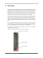
1
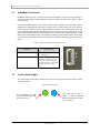
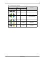
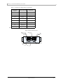
Third party information brought
to you courtesy of Dell.
InfiniScale® III 16+8 Port 20Gb/s InfiniBand
Switch for Dell PowerEdge M1000e-series
Blade Enclosures User Manual
PN: M2401G
Rev 1.7
Mellanox Technologies
2
Copyright 2008. Mellanox Technologies, Inc. All Rights Reserved.
Mellanox Technologies ConnectX, InfiniBlast, InfiniBridge, InfiniHost, InfiniRISC, InfiniScale,
and InfiniPCI are registered trademarks of Mellanox Technologies, Ltd. Virtual Protocol Interconnect is a trademark of Mellanox Technologies, Ltd. Dell and the Dell logo are trademarks of Dell
Inc. All other marks and names mentioned herein may be trademarks of their respective companies.
Third party information brought to you courtesy of Dell.
InfiniScale® III 16+8 Port 20Gb/s InfiniBand Switch for Dell PowerEdge M1000e-series Blade
Enclosures User Manual
Document Number: 2948
Mellanox Technologies, Inc.
350 Oakmead Parkway
Sunnyvale, CA 94086
U.S.A.
www.Mellanox.com
Tel: (408) 970-3400
Fax: (408) 970-3403
Mellanox Technologies Ltd
PO Box 586 Hermon Building
Yokneam 20692
Israel
Tel: +972-4-909-7200
Fax: +972-4-959-3245
NOTE:
THIS INFORMATION IS PROVIDED BY MELLANOX FOR INFORMATIONAL PURPOSES ONLY AND ANY
EXPRESS OR IMPLIED WARRANTIES, INCLUDING, BUT NOT LIMITED TO, THE IMPLIED WARRANTIES OF
MERCHANTABILITY AND FITNESS FOR A PARTICULAR PURPOSE ARE DISCLAIMED. IN NO EVENT SHALL
MELLANOX BE LIABLE FOR ANY DIRECT, INDIRECT, INCIDENTAL, SPECIAL, EXEMPLARY, OR CONSEQUENTIAL DAMAGES (INCLUDING, BUT NOT LIMITED TO, PROCUREMENT OF SUBSTITUTE GOODS OR
SERVICES; LOSS OF USE, DATA, OR PROFITS; OR BUSINESS INTERRUPTION) HOWEVER CAUSED AND ON
ANY THEORY OF LIABILITY, WHETHER IN CONTRACT, STRICT LIABILITY, OR TORT (INCLUDING NEGLIGENCE OR OTHERWISE) ARISING IN ANY WAY OUT OF THE USE OF THIS HARDWARE, EVEN IF ADVISED
OF THE POSSIBILITY OF SUCH DAMAGE.
Rev 1.7
Mellanox Technologies
M3601Q 16+16 Port 40Gb/s InfiniBand Switch User Manual
3
Contents
Contents
3
About this Manual
4
Revision History
5
Chapter 1
Overview
6
1.1
1.2
7
7
Chapter 2
Chapter 3
Chapter 4
InfiniBand Connectors
Switch Status Lights
Installation and Basic Operation
9
2.1
2.2
Installation Safety Warnings
Mechanical Installation
2.2.1 Removing an Old Switch From the Chassis
2.2.2 Removing a Blank Cover Plate From the Chassis
2.2.3 Installing the Mellanox M2401G Switch Into the Dell Chassis
2.3 Power Connections and Initial Power On
2.4 InfiniBand Cable Installation
10
11
11
12
12
12
13
Cluster Management and Firmware
14
3.1
3.2
14
14
14
Network Management and Clustering Software
Updating Firmware
3.2.1 Instructions for Reprogramming Over the InfiniBand Network
Troubleshooting
17
Appendix A
Specifications
18
Appendix B
Mechanical Drawing
19
Appendix C
EMC Certification Statements
20
Appendix D
InfiniBand Connector Pinout
22
Appendix E
Avertissements de sécurité d’installation
24
Appendix F
Installation - Sicherheitshinweise
26
Mellanox Technologies
Rev 1.7
4
About this Manual
This manual describes the installation and basic use of the Mellanox M2401G 16+8 Port 20Gb/s
InfiniBand Switch for Dell PowerEdge M1000e-series Blade Enclosures.
Intended Audience
This manual is intended for users and system administrators responsible for installing and setting
up the switch platforms listed above.
The manual assumes familiarity with the InfiniBand® Architecture Specification.
Related Documentation
The documentation set accompanying the Mellanox M2401G includes the following:
Table 1 - Reference Documents
InfiniBand Architecture Specification Volume 1 Release 1.2.1 and Volume 2 release
1.2.1
InfiniBand architecture specification descriptions
Mellanox OFED Stack
The Mellanox OFED stack provides a tool set to manage InfiniBand fabric clusters. The
stack with user’s manual can be downloaded at:
http://www.mellanox.com > Downloads > InfiniBand SW/Drivers,
Be sure to download the stack that matches your OS.
Mellanox Firmware Tools (MFT)
User’s Manual
Document # 2329
The MFT (Mellanox Firmware Tools) package is a set of firmware tools. The manual
supplied with this package provides an overview of the firmware its installation and
replacement. The MFT can be downloaded with its documentation at:
http://www.mellanox.com > Downloads > Firmware Tools
Online Resources
• Mellanox Technologies Web pages: http://www.mellanox.com
• Dell Support Web pages: http://support.dell.com
Conventions
Throughout this manual, the name M2401G and the term switch are used to describe the 16+8 port
20Gb/s InfiniBand switch for the Dell M1000e, unless explicitly indicated otherwise.
Rev 1.7
Mellanox Technologies
M3601Q 16+16 Port 40Gb/s InfiniBand Switch User Manual
5
Revision History
Table 2 - Revision History Table
Date
Revision
Description
Mar. 2009
Rev 1.7
Added Dell flat black Logo
Dec. 2008
Rev 1.6
Minor fixes to Rev 1.5
Dec. 2008
Rev 1.5
Minor fixes to Rev 1.4
Added Instructions for Reprogramming Over the InfiniBand Network
Nov. 2008
Rev 1.4
Added Dell logo and Dell 3rd party info statement
Replaced Mellanox address
Fixed Links to new web site
Aug. 2008
Rev 1.3
Added Certs and Link to FW
Aug. 2008
Rev 1.2
Added appendix with safety warnings in French for Canada Certification
July 2008
Rev 1.1
Fixed Max Ambient Temperature
June 2008
Rev 1.0
First Draft
Mellanox Technologies
Rev 1.7
6
1
Overview
The Mellanox M2401G 20Gb/s InfiniBand Switch Blade for Dell PowerEdge M1000e-series Blade
Enclosures provides a high bandwidth, low latency, low power fabric for Enterprise Data Center
and High-Performance Computing environments. Based on the third generation InfiniScale® III
InfiniBand switch device, the platform delivers an ideal balance between cost and performance.
When used in conjunction with ConnectX® InfiniBand dual port I/O cards clustered data bases,
parallelized applications and transactional services applications will achieve significant performance improvements resulting in reduced completion time and lower cost per operation.
The switch platform comes pre-installed with all necessary firmware, and configured for standard
operation within an InfiniBand fabric, and requires an InfiniBand compliant Subnet Manager running from one of the hosts. All that is required for normal operation is to follow the usual precautions for installation and connection from the switch to the HCAs or other switches. Once
connected, the Subnet Management software automatically configures and begins utilizing the
switch.
It is recommended that Mellanox OpenFabrics software package be installed on all nodes connected to the M2401G. The software package provides a subnet manager and network management
tools as well as connectivity software for servers and storage, and is available on the Mellanox web
site. See “Cluster Management and Firmware” on page 14. for more information.
Basic installation, hot-swapping components and hardware maintenance is covered in “Installation and Basic Operation” on page 9.
The M2401G switch has a Hot Swap controller and a PSOC Management IC.
Figure 1: Switch Front Panel and Locking Mechanism
Locking Mechanism
Switch Status Lights
Rev 1.7
Mellanox Technologies
M3601Q 16+16 Port 40Gb/s InfiniBand Switch User Manual
7
1.1
InfiniBand Connectors
InfiniBand connectivity has 8 microGiGa connectors through the front panel. The remaining 16
interfaces are through the AirMax Midplane Connector out the back of the switch. Figure 1 shows
the front 8 ports.
Each of the InfiniBand ports has two LEDs located next to the connector. The green LED, when lit,
indicates that a valid physical connection to the other system (switch or HCA port) exists. The yellow LED when lit, indicates that the Subnet Manager is running and a valid data link exists. The
yellow LED illuminates when the InfiniBand network is discovered over the physical link. A valid
data activity link without data transfer is designated by a constant yellow LED indication. A valid
data activity link with data transfer is designated by a blinking yellow LED indication. If the LEDs
are not active, either the physical link or the logical link (or both) connections have not been established.
Figure 2: Physical and Logical Link Indication LEDs
LED Name
1.2
Connection Status
Physical Link - Green
Off – No Physical Link
ON – Physical Link
Data Activity - Yellow
Blinking – indicates Data Transfer
Constant on – indicates Link exists
with no Data Transfer taking place
Off with green LED lit – indicates that
the Subnet Manager may not be
running
Switch Status Lights
The switch Status lights indicate whether the switch is receiving power from the chassis, and the
state of the switch.
Figure 3: Indicator LEDs
This LED can be blue or
amber. A fault is indicated
when the amber LED is blinking. See Table 3.
The I/O Module is on and
ready when both the blue and
green LEDs are lit.
Mellanox Technologies
Rev 1.7
8
Table 3 - IOM states and LED configurations:
LED
Switch Status
Indication
Green
Status
OFF
OFF
OFF
ON
OFF
Boot in Progress
Switch not ready
ON
BLINKING BLUE
The CMC is identifying
the newly installed switch
ON
ON BLUE
Switch is on and operating Normally
ON
ON or BLINKING
AMBER
Fault in System
Self-diagnosed
OFF
ON or BLINKING
AMBER
Fault in System
CMC-detected
Blinking Blue
Rev 1.7
Mellanox Technologies
M3601Q 16+16 Port 40Gb/s InfiniBand Switch User Manual
9
2
Installation and Basic Operation
Installation and initialization of the switch platform are straightforward processes, requiring attention to the normal mechanical, power, and thermal precautions for rack-mounted equipment. The
switch platform does not require any programming or configuration to operate as a basic InfiniBand switch and includes all of the necessary functionality to operate with external standard InfiniBand Subnet Management software.
This section describes the installation process and basic operation of the switch platform. Please
first read the warnings sub-section carefully before carrying on with installation procedures.
Suitable electrical, mechanical and fire enclosure shall be provided by the end user.
Mellanox Technologies
Rev 1.7
10
2.1
Installation Safety Warnings
1.
Installation Instructions
Read all installation instructions before connecting the equipment to the power source.
2.
Over-temperature
This equipment should not be operated in an area with an ambient temperature exceeding the maximum recommended: °C (°F). Moreover, to guarantee proper air flow, allow
at least 8cm (3 inches) of clearance around the ventilation openings.
3.
Stacking the Chassis
The chassis should not be stacked on any other equipment. If the chassis falls, it can
cause bodily injury and equipment damage.
4.
During Lightning - Electrical Hazard
During periods of lightning activity, do not work on the equipment or connect or disconnect cables.
5.
Copper InfiniBand Cable Connecting/Disconnecting
Copper InfiniBand cables are heavy and not flexible, as such they should be carefully
attached to or detached from the connectors. Refer to the cable manufacturer for special
warnings and instructions.
6.
Rack Mounting and Servicing
When this product is mounted or serviced in a rack, special precautions must be taken to
ensure that the system remains stable. In general you should fill the rack with equipment
starting from the bottom to the top.
7.
Equipment Installation
This equipment should be installed, replaced, or serviced only by trained and qualified
personnel.
Rev 1.7
Mellanox Technologies
M3601Q 16+16 Port 40Gb/s InfiniBand Switch User Manual
11
8.
Equipment Disposal
Disposal of this equipment should be in accordance to all national laws and regulations.
9.
Local and National Electrical Codes
This equipment should be installed in compliance with local and national electrical
codes.
2.2
Mechanical Installation
These switches are hot pluggable. It is not necessary to power down the Dell Chassis to install a
new switch or to replace an old switch with a new one.
Figure 4: Rear View of the Dell PowerEdge M1000e Chassis
Latch Release Buttons
Locking Arms
Channel 1 slots
A1 B1 C1
Channel 2 slots
C2 B2 A2
Note: M2401G blades are not allowed in the Fabric A slots.
2.2.1
Removing an Old Switch From the Chassis
1. Remove any locking cables or screws that secure the old switch into the chassis.
2. Disconnect all of the InfiniBand cables from the front of the switch to be removed.
Mellanox Technologies
Rev 1.7
12
3. Unlock the switch from the chassis by pushing the red latch release button.
4. Pull the locking arm down to a position perpendicular to the front of the chassis.
5. Pull the switch out of the chassis using the locking arm.
6. Install either a new switch or a blank IOM within one minute.
2.2.2
Removing a Blank Cover Plate From the Chassis
1. Remove any locking cables or screws that secure the blank cover plate into the chassis.
2. Unlock the blank cover plate by pushing the red latch release button.
3. Pull the locking arm down to a position perpendicular to the front of the chassis.
4. Pull the cover plate out of the chassis using the locking arm.
5. Install either a new switch or reinstall a blank IOM within one minute.
2.2.3
Installing the Mellanox M2401G Switch Into the Dell Chassis
Note: Make sure the Chassis is stable on a solid floor and that the Chassis is filled from the bottom up. This will keep the center of gravity as low as possible reducing risk of tipping.
Note: The M2401G IOMs are only to be installed in Fabric B or Fabric C slots, and at least one
blade must have a matching ConnectX I/O card installed to support data flow. Within each fabric
type, you must install a module in the fabric's channel 1 slot before installing a module in the
fabric's channel 2 slot. For example, you must install a module in slot C1 before installing a
module in slot C2. Modules may be installed in Fabric B and C independently (you do not need
to install modules in Fabric B before installing modules in Fabric C slots). Refer to the Dell
PowerEdge M1000e Hardware Owners Manual for more information.
1. Follow the instructions in Section 2.2.1 or Section 2.2.2 to remove an old switch or a Blank
cover plate.
2. On the new switch, push the red latch release button.
3. Pull the lever forward until the lever is perpendicular to the front panel.
4. Push the switch into the slot until the latching mechanism is against the bar.
5. Push the lever on the latching mechanism up, making sure that the latching mechanism catches
the locking bar. The lever should now be parallel to the front panel.
6. Check the indicator lights to make sure the switch has power.
The installer should use a rack cable to support the mechanical and environmental characteristics of
a fully populated switch platform Chassis.
The rack mounting is designed to fit the PowerEdge M1000e Chassis. Take precautions to guarantee proper ventilation for air intake at the front of the chassis and
exhaust at the rear in order to maintain good airflow at ambient temperature. Cable
routing in particular should not impede the air exhaust from the chassis.
2.3
Power Connections and Initial Power On
Caution: The switch platform will automatically power up when AC power is applied. There is no
power switch. Immediately upon closing the latching mechanism check to make sure that the
green switch LED is lit.
Rev 1.7
Mellanox Technologies
M3601Q 16+16 Port 40Gb/s InfiniBand Switch User Manual
13
2.4
InfiniBand Cable Installation
All cables can be inserted or removed with the unit power on. To insert a cable, press the connector
into the port receptacle until the connector is firmly seated. The green LED indicator below each
port will light when the physical connection is established (that is, when the unit is powered on and
a cable is plugged into the port with a functioning port plugged into the other end of the connector).
After plugging in a cable, lock the connector using the latching mechanism particular to the cable
vendor. The yellow LED will light if the subnet manager is running (non blinking indicating that no
data is being transferred yet). When a logical connection is made the yellow LED will blink signifying data is being transferred.
To remove, disengage the locks and slowly pull the connector away from the port receptacle. Both
LED indicators will turn off when the cable is unseated.
Care should be taken not to impede the air exhaust flow through the chassis.
Note: Cable lengths should be used which allow for routing horizontally around to the side of the
chassis before bending upward or downward in the rack.
Mellanox Technologies
Rev 1.7
14
3
Cluster Management and Firmware
3.1
Network Management and Clustering Software
Download and install, on all nodes, the Mellanox OpenFabric software package for Linux, Windows, or other operating systems from the Mellanox software website:
http://www.mellanox.com > Downloads > InfiniBand SW/Drivers
This software package provides connectivity for server and storage systems utilizing High Performance Computing (HPC) or enterprise data center (EDC) applications across an InfiniBand fabric.
It also provides a Subnet Manager for simple network configuration and network administration
and diagnostic tools for network management.
3.2
Updating Firmware
The switch is delivered with the latest Firmware available at the time of production. New firmware
versions will be posted on the Mellanox firmware download page. Firmware can be updated inband using the Mellanox Firmware Tools (MFT).
You will need the Mellanox Firmware Tools package available in MLNX_OFED to update firmware for this switch. It also can be downloaded from:
http://www.mellanox.com > Downloads > Firmware Tools
The latest firmware can be found at:
http://www.mellanox.com >Support >Dell
3.2.1
Instructions for Reprogramming Over the InfiniBand Network
To update an MT47396 InfiniScale III switch devices having a specific GUID (for example,
0x00000006660abcd0) or LID, the following are the recommended steps to update the device firmware.
1. Make sure all subnet ports are in the active state. One way to check this is to run opensm, the
Subnet Manager.
[root@mymach]> /etc/init.d/opensmd start
opensm start
[ OK ]
2. Make sure the local ports are active by running ‘ibv_devinfo’.
3. Obtain the device LID. There are two ways to do that:
I. Using the “mst ib add” command:
The “mst ib add” runs the ibdiagnet tool to discover the InfiniBand fabric and then lists the discovered IB
nodes as an mst device under /dev/mst/ directory. These devices can be used for access by other MFT
tools.
[root@mymach]> mst ib add
-I- Running ibdiagnet to discover the fabric ...
Loading IBDIAGNET from: /usr/local/lib/ibdiagnet1.2
-W- Topology file is not specified.
Rev 1.7
Mellanox Technologies
M3601Q 16+16 Port 40Gb/s InfiniBand Switch User Manual
15
Reports regarding cluster links will use direct routes.
Loading IBDM from: /usr/local/lib/ibdm1.2
-I- Using port 1 as the local port.
-I- Discovering ... 3 nodes (2 Switches & 1 CA-s) discovered.
-I---------------------------------------------------I- Bad Guids/LIDs Info
-I---------------------------------------------------I- skip option set. no report will be issued
-I---------------------------------------------------I- Links With Logical State = INIT
-I---------------------------------------------------I- skip option set. no report will be issued
-I---------------------------------------------------I- PM Counters Info
-I---------------------------------------------------I- skip option set. no report will be issued
-I---------------------------------------------------I- Fabric Partitions Report (see ibdiagnet.pkey for a full hosts list)
-I---------------------------------------------------I- skip option set. no report will be issued
-I---------------------------------------------------I- IPoIB Subnets Check
-I---------------------------------------------------32
-I- skip option set. no report will be issued
-I---------------------------------------------------I- Bad Links Info
-I---------------------------------------------------I- No bad link were found
----------------------------------------------------------------I- Stages Status Report:
STAGE
Errors Warnings
Bad GUIDs/LIDs Check
0
0
Link State Active Check
0
0
Performance Counters Report
0
0
Partitions Check
0
0
IPoIB Subnets Check
0
0
Please see /tmp/ibdiagnet.log for complete log
----------------------------------------------------------------I- Done. Run time was 1 seconds.
-I- Added 3 in-band devices
[root@mymach]>
To list the discovered mst inband devices run “mst status”.
[root@mymach]> mst status
MST modules:
-----------MST PCI module loaded
MST PCI configuration module loaded
...
Inband devices:
------------------/dev/mst/CA_MT25418_sw005_HCA-1_lid-0x0001
/dev/mst/SW_MT47396_lid-0x0011
/dev/mst/SW_MT48438_lid-0x0003
[root@mymach]>
Mellanox Technologies
Rev 1.7
16
II. Using the ibnetdiscover tool:
Run:
[root@mymach]# ibnetdiscover | grep 00000006660abcd0 | grep -w Switch
Switch 24 "S-00000006660abcd0" "MT47396 Infiniscale-III Mellanox Technologies"
base port 0 lid 17 lmc 0
Note: The resulting LID is given as a decimal number.
4. Run mlxburn with the LID retrieved in step #3 above to perform the In-Band burning operation.
Burn the InfiniScale III switch:
[root@mymach]> mlxburn -dev /dev/mst/SW_MT47396_lid-0x0011 -fw ./IS3FW.BIN
-I- Reading PSID from board
-I- Using auto detected configuration file ./MT34000LE-A00.INI (PSID =
MT_0070000001)
-I- Generating image ... MFT User’s Manual
33
Rev 1.01 Mellanox Technologies
- Checking primary image
- OK
Current FW Version: 1.0.0
New FW Version:
1.0.0
- Burning secondary image
- OK
- Verifying secondary image - OK
- Burning primary image
- OK
- Verifying primary image
- OK
-I- Image burn completed successfully.
Rev 1.7
Mellanox Technologies
M3601Q 16+16 Port 40Gb/s InfiniBand Switch User Manual
17
4
Troubleshooting
As soon as a switch is plugged in make sure that the power LED comes on.
The power LED for the switch does not come on:
1. Check that the chassis has power.
2. Remove and reinstall the switch.
The status LED for the switch is blinking amber:
1. remove the switch from the chassis and re-insert it (verify that the switch is all the way in the
chassis and the lever is firmly closed).
2. If the amber LED continues to blink, replace the switch.
The link LED for the InfiniBand connector does not come on:
1. Check that both ends of the cable are connected.
2. Check that the locks on the ends are secured.
3. Make sure that the latest FW version is installed on both the I/O card and the switch.
4. Make sure that at least one blade has a matching I/O card installed to support data flow.
5. If media adapters are used check that the all connections are good, tight, and secure.
The activity LED does not come on:
Check that the Subnet Manager has been started.
The power LED for the switch shuts off:
1. Check that the there is adequate ventilation.
2. Make sure that there is nothing blocking the front or rear ventilation openings of the chassis.
Mellanox Technologies
Rev 1.7
18
Appendix A: Specifications
Table 4 - M2401G Specification Data
Physical
Power and Environmental
H x W x D: 1.16 x 10.04 inches
272.50 x 29.45 x 255.20 mm
Weight: 1.5 Kg fully configured
Mounting: Vertically mounted rack
SerDes Speeds 10, 20 Gb/s per port
Connectors: microGiGaCN
8 external CX4 connectors
4x4 internal backplane connectors
Protocol Support
Maximum Power:
Dissipated Power:
Power through
connector:
Temperature:
Humidity:
Altitude:
Shock:
Vibration:
50W
33.5W
1.65 W per port
0o to 45o Celsius
10% - 90% non-condensing
Regulatory Compliance
InfiniBand: Auto-Negotiation of 10Gb/s or 20Gb/s
QoS: 8 InfiniBand Virtual Lanes for all ports
Management: Baseboard, Performance, and Device management Agents for full InfiniBand In-Band
Management
Safety: US/Canada: cTUVus
EU: IEC60950
International: CB
EMC: USA: FCC, Class A
Canada: ICES, Class A
EU: CE Mark (EN55022 Class A,
EN55024, EN61000-3-2,
EN61000-3-3)
Japan: VCCI, Class A
Korea: RRL (MIC), Class A
Australia/New Zealand: C-Tick
Class A
ENVIRONMENTAL EU: IEC 60068-2-64: Random
Vibration
EU: IEC 60068-2-29: Shocks,
Type I / II
EU: IEC 60068-2-32: Fall Test
Reliability, Availability and Serviceability
Features
Scalability and Performance
Switching Performance: Simultaneous wire-speed any port to any port
Addressing: 48K Unicast Addresses Max. per Subnet
16K Multicast Addresses per Subnet
Switching Capacity 960 Gb/s
Rev 1.7
Mellanox Technologies
M3601Q 16+16 Port 40Gb/s InfiniBand Switch User Manual
19
Appendix B: Mechanical Drawing
Figure 4 Mechanical Drawing of the Switch
Mellanox Technologies
Rev 1.7
20
Appendix C: EMC Certification Statements
C.1: FCC Statements (USA)
Class A Statements:
§ 15.21
Statement
Warning! Changes or modifications to this equipment not expressly approved by the party
responsible for compliance (Mellanox Technologies) could void the user's authority to operate
the equipment.
§15.105(a)
Statement
NOTE: This equipment has been tested and found to comply with the limits for a Class A digital
device, pursuant to Part 15 of the FCC Rules. These limits are designed to provide reasonable protection against harmful interference when the equipment is operated in a commercial environment.
This equipment generates, uses, and can radiate radio frequency energy and, if not installed and
used in accordance with the instruction manual, may cause harmful interference to radio communications. Operation of this equipment in a residential area is likely to cause harmful interference in
which case the user will be required to correct the interference at his own expense.
C.1.1 EN Statements (Europe)
EN55022 Class A Statement:
Warning! This is a class A product. In a domestic environment this product may cause radio
interference, in which case the user may be required to take adequate measures.
C.1.2 ICES Statements (Canada)
Class A Statement:
“This Class A digital apparatus complies with Canadian ICES-003.
Cet appareil numérique de la classe A est conforme à la norme NMB-003 du Canada.”
Rev 1.7
Mellanox Technologies
M3601Q 16+16 Port 40Gb/s InfiniBand Switch User Manual
21
C.1.3 VCCI Statements (Japan)
Class A Statement:
(Translation - "This is a Class A product based on the standard of the Voluntary Control
Council for Interference by Information Technology Equipment (VCCI). If this equipment is
used in a domestic environment, radio interference may occur, in which case the user may be
required to take corrective actions.")
C.1.4 MIC Certification (Korea)
Korea's "Regulation for Certification of Information and Communication Equipment," requires
EMC testing and certification for many electronic products. Korean EMC certifications are issued
by Radio Research Laboratory (RRL), which is organized under the Ministry of Information and
Communications (MIC). EMC testing includes electromagnetic emissions (EMI) and susceptibility (EMS). Certified equipment is labeled with the MIC mark and certification number.
Translation:
Class A Device
This device is registered for EMC requirements for industrial use. The seller or
buyer should be aware of this. If this type was sold or purchased by mistake, it should be
replaced with a residential-use type.
Mellanox Technologies
Rev 1.7
22
.
Appendix D: InfiniBand Connector Pinout
Figure 5: InfiniBand Connector
Pinout
Conn
1X
S10
S9
S12
S11
S14
S13
S16
IBtxIp(3)
IBtxOn(3)
IBtxIn(3)
IBtxOp(2)
IBtxIp(2)
IBtxOn(2)
IBtxIn(2)
IBtxOp(1)
IBtxIp(1)
IBtxOn(1)
IBtxIn(1)
IBtxOp(0)
IBtxIp(0)
IBtxOn(0)
IBtxIn(0)
H1
G1
G2
G3
G4
G5
G6
G7
G8
G9
H2
GND
GND
GND
GND
GND
GND
GND
Sense-3.3V
Vcc
GND
GND
S15
IBtxOp(3)
Table 5 - Connector Pin to Signal Name Correspondence
Rev 1.7
Connector Pin
Number
Connector Pin Name
Signal Name
S1
IBtxIp(0)
IB_Px_R1_P
S2
IBtxIn(0)
IB_Px_R1_N
S3
IBtxIp(1)
IB_Px_R2_P
S4
IBtxIn(1)
IB_Px_R2_N
S5
IBtxIp(2)
IB_Px_R3_P
S6
IBtxIn(2)
IB_Px_R3_N
S7
IBtxIp(3)
IB_Px_R4_P
S8
IBtxIn(3)
IB_Px_R4_N
S9
IBtxOn(3)
IB_Px_T4_N
S10
IBtxOp(3)
IB_Px_T4_P
S11
IBtxOn(2)
IB_Px_T3_N
Mellanox Technologies
S7
S8
S5
S6
S3
S4
S1
S2
M3601Q 16+16 Port 40Gb/s InfiniBand Switch User Manual
23
Table 5 - Connector Pin to Signal Name Correspondence
Connector Pin
Number
Connector Pin Name
Signal Name
S12
IBtxOp(2)
IB_Px_T3_P
S13
IBtxOn(1)
IB_Px_T2_N
S14
IBtxOp(1)
IB_Px_T2_P
S15
IBtxOn(0)
IB_Px_T1_N
S16
IBtxOp(0)
IB_Px_T1_P
G1-G6, G9, H1-H2
Signal Ground
G7
Sense-3.3V
G8
Vcc
Px in the signal name signifies Port # x. This switch has 8 external ports.
Figure 6: Pinout Connector View
S16
G9
S8
S2
G1
S1
S15
G8
G2
S9
Mellanox Technologies
Rev 1.7
24
Appendix E: Avertissements de sécurité d’installation
1.
Instructions d’installation
Lisez toutes les instructions d’installation avant de brancher le matériel à la source
d’alimentation électrique.
2.
Température excessive
Ce matériel ne doit pas fonctionner dans une zone avec une température ambiante
dépassant le maximum recommandé de 45°C (113°F). En outre, pour garantir un bon
écoulement de l’air, laissez au moins 8 cm (3 pouces) d’espace libre autour des ouvertures de ventilation.
3.
Empilage du châssis
Le châssis ne doit pas être empilé sur un autre matériel. Si le châssis tombe, il peut provoquer des blessures corporelles et des dégradations de biens.
4.
Orages – dangers électriques
Pendant un orage, il ne faut pas utiliser le matériel et il ne faut pas brancher ou
débrancher les câbles.
5.
Branchement/débranchement des câbles InfiniBand en cuivre
Les câbles InfiniBand en cuivre sont lourds et ne sont pas flexibles, il faut donc faire
très attention en les branchant et en les débranchant des connecteurs. Consultez le fabricant des câbles pour connaître les mises en garde et les instructions spéciales.
6.
Montage et entretien sur baie
Lorsque ce produit est monté ou entretenu sur baie, il faut prendre des précautions spéciales pour s’assurer que le système reste stable. En général, il faut remplir la baie avec
du matériel de bas en haut.
7.
Installation du matériel
Ce matériel ne doit être installé, remplacé ou entretenu que par du personnel formé et
qualifié.
Rev 1.7
Mellanox Technologies
M3601Q 16+16 Port 40Gb/s InfiniBand Switch User Manual
25
8.
Elimination du matériel
L’élimination de ce matériel doit s’effectuer dans le respect de toutes les législations et
réglementations nationales en vigueur.
9.
Codes électriques locaux et nationaux
Ce matériel doit être installé dans le respect des codes électriques locaux et nationaux.
Mellanox Technologies
Rev 1.7
26
Appendix F: Installation - Sicherheitshinweise
1.
Installationsanleitungen
Lesen Sie alle Installationsanleitungen, bevor Sie das Gerät an die Stromversorgung
anschließen.
2.
Übertemperatur
Dieses Gerät sollte nicht in einem Bereich mit einer Umgebungstemperatur über der
maximal empfohlenen Temperatur von 45°C (113°F) betrieben werden. Außerdem
sollten mindestens 8 cm (3 in.) Freiraum um die Belüftungsöffnungen sein, um einen
einwandfreien Luftstrom zu gewährleisten.
3.
Stapeln des Chassis
Das Chassis sollte nicht auf andere Geräte gestapelt werden. Wenn das Chassis herunterfällt, kann es zu Verletzungen und Beschädigungen an Geräten führen.
4.
Bei Gewitter - Elektrische Gefahr
Arbeiten Sie während eines Gewitters und Blitzschlag nicht am Gerät, schließen Sie
keine Kabel an oder ab.
5.
Anschließen/Trennen von InfiniBand-Kupferkabel
InfiniBand-Kupferkabel sind schwer und nicht flexible. Deshalb müssen sie vorsichtig
an die Anschlüsse angebracht bzw. davon getrennt werden. Lesen Sie die speziellen
Warnungen und Anleitungen des Kabelherstellers.
6.
Rack-Montage und Wartung
Wenn dieses Produkt in einem Rack montiert oder gewartet wird, sind besondere Vorsichtsmaßnahmen zu ergreifen, um die Stabilität des Systems zu gewährleisten. Im
Allgemeinen sollten Sie das Gestell von unten nach oben mit Geräten füllen.
7.
Geräteinstallation
Diese Gerät sollte nur von geschultem und qualifiziertem Personal installiert, ausgetauscht oder gewartet werden.
Rev 1.7
Mellanox Technologies
M3601Q 16+16 Port 40Gb/s InfiniBand Switch User Manual
27
8.
Geräteentsorgung
Die Entsorgung dieses Geräts sollte unter Beachtung aller nationalen Gesetze Bestimmungen erfolgen.
9.
Regionale und nationale elektrische Bestimmungen
Dieses Gerät sollte unter Beachtung der regionalen und nationalen elektrischen
Bestimmungen installiert werden.
Mellanox Technologies
Rev 1.7