1
Version 3.1
Produced in Sep. 2001
R
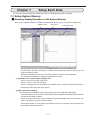
SLadder
logic programmning software
Model name
JW-100SP
Instruction Manual
Thank you for purchasing the ladder logic programming software JW-100SP.
Please read the instruction manual carefully in order to apply the software correctly by understanding its
functions and operations.
Please keep this instruction manual near you. It will certainly help you when you encounter problems.
Note
・This manual describes the version 5.10
2.0 of JW-100SP
Note
・Despite of our effort to create products with excellency, should you find any deficiency, please notify
the dealer where you obtained the software or our customer service companies.
・Users are not authorized to copy the whole or the part of this instruction manual and software without
our consent.
・Due to the amelioration of the product, please understand that the materials of this instruction manual
and software are subject to change without notification.
・We are not held responsible for any damages created as the result of using this software , nor
damages claimed by the third party as the result of using this software.
Ladder logic programming software JW-100SP
■ Instruction Manual
Chapter 1 Introduction
Chapter 2 Setup
Chapter 3 Basic operation
Chapter 4 Let’s create program
Chapter 5 Menu operation
Chapter 6 Program edit
Chapter 7 Setup each data
Chapter 8 Monitor
Chapter 9 Print
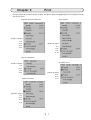
Table of Contents
Chapter 1 Introduction ・・・・・・・・・・・・・・・・・・・・・・・・・・・・・・・・・・・・・・・・・・・・・・・・・ 1・1∼9
1-1 Features 1•1
1-2 Compatible PC models 1•2
1-3 System requirements 1•2
1-4 Connection between the personal computer and the PC
■ Basic system organization 1•3
■ System organization using communication 1•4
1-5 Product organization 1•8
■ Ladder logic programming software (JW-100SP) 1•8
■ Communication adapter (JW-100SA) 1•8
1-6 Caution 1•8
■ On-line caution up on using the monitor 1•8
1-7 Conventions used in this manual 1•9
■ Display of menu, command, dialog box
1•9
■ Display of mouse operation 1•9
■ Display of key operation
1•3
1•9
Chapter 2 Setup ・・・・・・・・・・・・・・・・・・・・・・・・・・・・・・・・・・・・・・・・・・・・・・・・・・・・・・・ 2・1∼4
Chapter 3 Basic operation ・・・・・・・・・・・・・・・・・・・・・・・・・・・・・・・・・・・・・・・・・・・・・ 3・1∼27
3-1 Starting-up and quitting 3•1
■ Starting-up JW-100SP
3•1
■ Quitting JW-100SP 3•2
3-2 List of files about JW-100SP 3•3
3-3 Screen configuration 3•4
■ Screen when you create new file 3•4
■ Main toolbar 3•5
■ Sub toolbar
3•6
■ Message bar 3•7
■ Toolbar for editing ladder 3•8
■ Toolbar for editing mnemonic 3•9
■ Toolbar for editing data
3•10
3-4 Kinds of windows 3•11
■ Main window 3•11
■ Basic window 3•12
■ Other windows 3•15
3-5 Selection of commands
3•19
■ Click button of the oolbar 3•19
■ Select the command from the menu 3•19
■ Select a command from the shortcut menu 3•20
■ Using the shortcut keys 3•21
3-6 Function summary
3•22
■ File
3•22
■ Edit
3•23
■ Instruction 3•24
Table of Contents-1
■ Monitor
■ Display
■ Setup
■ PC
■ Tools
3•24
3•25
3•25
3•26
3•26
■ Window 3•27
■ Help
3•27
Chapter 4 Let's create program ・・・・・・・・・・・・・・・・・・・・・・・・・・・・・・・・・・・・・・・・・ 4・1∼21
4-1 Start-up JW-100SP
4•2
4-2 Create ladder program 4•4
■ Setup input type 4•4
■ Inputting A contact, B contact and coil 4•5
■ Inputting timer and counter
4•9
■ Inputting application instruction 4•10
■ Program check and conversion to mnemonic
4-3 PC transfer/monitor 4•16
4-4 Print
4•19
■ The print example 4•21
4•13
Chapter 5 Menu operation ・・・・・・・・・・・・・・・・・・・・・・・・・・・・・・・・・・・・・・・・・・・・・・ 5・1∼83
5-1 File 5•3
■ New
5•4
■ Open
5•6
■ Close
5•7
■ Save
5•8
■ Save as
5•8
■ FD Verify 5•9
■ Page Setup
5•9
■ Print Program
5•9
■ Print Preview
5•9
■ Printer Setup
5•9
■ Quit
5•9
■ Export Files (Data/Symbol)
■ Import Files (Data/Symbol)
5-2 Edit
5•12
■ Undo
5•13
■ Cut
5•13
■ Copy
5•13
■ Paste
5•13
■ Image Copy
5•13
■ Find
5•14
■ Find Previous
5•17
■ Find Next
5•17
■ Find Coil
5•17
■ Insert Cell
5•18
■ Insert Row
5•18
■ Delete Cell
5•18
■ Delete Row
5•18
5•10
5•11
Table of Contents-2
■ Create Line Comment 5•19
■ Zoom
5•20
■ Jump
5•21
■ Library
5•23
■ Program Check 5•24
■ Converts data in batch 5•25
■ Replacing Contacts
5•26
■ Assigns symbol 5•27
5-3 Instruction 5•29
5-4 Monitor
5•30
5-5 Display
5•31
■ Main toolbar /Sub toolbar /Status bar /Tree bar /Toolbar for editing ladder /Toolbar for editing
mnemonic /Toolbar for editing data /Message bar 5•33
■ Select address display type
5•34
■ View change
5•34
■ Select monitoring display type
5•35
■ Change segment file
5•36
■ Word wrap 5•37
■ Data list
5•38
■ Arrange ladder diagram 5•42
■ Displays in Symbol/Displays in comment/Displays in Symbol&Comment
5•43
■ Displays in binary notation/Displays in octal notation/Displays in decimal notation/Displays in decimal
notation(+/-)/Displays in hex notation /Displays in ASCII 5•43
■ Displays in byte/Displays in word/Displeys in double word
5•44
■ Displays in detail/Displays as a list 5•45
5-6 Setup
5•46
■ Select PC model 5•46
■ Select memory capacity
5•47
■ Setup communication 5•48
■ Memory clear
5•54
■ Setup input type 5•55
■ Setup display
5•56
■ Key assignment 5•57
■ Check input of same symbol 5•58
5-7 PC5•59
■ PC transfer
5•59
■ Run /Stop 5•62
■ PC operation
5•62
[1] I/O search
5•63
[2] Secret 5•64
[3] CU memory clear
5•65
[4] Parity check 5•66
[5] EEPROM
5•67
[6] I/O table automatic registration
5•68
■ PC monitor
5•69
[1] Error monitor 5•69
[2] Scan time monitor
5•70
[3] Clock monitor 5•71
Table of Contents-3
■ Modem Connection
5-8 Tool
5•73
■ Library
5•73
■ Multipoints monitor
■ Sampling Trace
■ Option parameter
■ CAD interface 5•74
5-9 Window
5•76
■ Open New Window
■ Overlap Display 5•78
■ Cascade Display
■ Arrange Icons 5•80
■ Window Name 1, 2, •••
5-10 Window 5•82
■ Find Topic
5•82
■ Version Data
5•83
5•72
5•73
5•73
5•73
5•77
5•79
5•81
Chapter 6 Program edit ・・・・・・・・・・・・・・・・・・・・・・・・・・・・・・・・・・・・・・・・・・・・・・・・・ 6・1∼47
6-1 Ladder programming 6•1
■ [Program:Ladder] window
6•1
■ Select address display type 6•2
■ Program Input method 6•4
[1] Direct input mode
6•4
[2] Dialog input mode
6•9
■ Setup input type
6•16
■ Edit circuit
6•18
[1] Over write/insert mode
6•18
[2] Modify circuit 6•18
[3] Delete circuit 6•22
[4] Insert circuit
6•22
[5] Copy circuit
6•23
[6] Move circuit
6•24
■ Copy circuit between windows
6•23
■ Library
6•26
[1] Register to library
6•26
[2] Read from library
6•31
■ Arrange ladder diagram
6•35
■ Converting ladder to mnemonic
6•38
■ Optimization of ladder 6•40
[1] Circuit by the optimization 6•40
[2] Optimization timing 6•41
6-2 Mnemonic programming
6•42
■ [Program:mnemonic] window
6•42
■ Input by mnemonic
6•42
■ Edit mnemonic 6•43
■ Converting mnemonic to ladder
6•44
6-3 Notes when editing a program
6•46
■ Notes for editing programs in several windows
6•46
Table of Contents-4
Chapter 7 Setup each data ・・・・・・・・・・・・・・・・・・・・・・・・・・・・・・・・・・・・・・・・・・・・・・ 7・1∼13
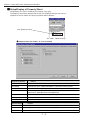
7-1 Setup system memory 7•1
■ Summary display /operation of system memory
■ Setup /display of property sheet
7•2
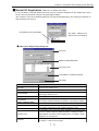
■ Manual I/O registration
7•3
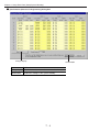
7-2 Setup data memory
7•5
■ Summary display /operation of data memory
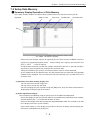
7-3 Setup symbol/comment
7•6
■ Summary display /operation of symbol/comment
■ Applying text file 7•7
7-4 Setup parameter 7•8
■ Summary display /operation of parameter 7•8
■ Setup model (special I/O module/option module)
■ Setup/display of property sheet
7•10
7-5 Setup other parameters
7•11
■ Summary display /operation of other parameters
■ Setup/display of property sheet
7•13
7•1
7•5
7•6
7•9
7•11
Chapter 8 Monitor ・・・・・・・・・・・・・・・・・・・・・・・・・・・・・・・・・・・・・・・・・・・・・・・・・・・・・・ 8・1∼31
8-1 Start monitoring, stop monitoring
8•1
[1] Monitor at the [Program:Ladder] window
8•1
[2] Monitor at the [Program:Mnemonic] window
8•3
[3] Monitor at the [System ] window 8•4
[4] Monitor at the [Data] window
8•5
[5] Monitor at the [Parameter] window
8•6
[6] Monitor several windows at the same time
8•7
8-2 Multipoints monitor
8•8
[1] Function
8•8
[2] Menu operation
8•11
8-3 Sampling trace 8•15
[1] Sampling trace order
8•16
[2] Menu of the [Sampling Trace] window
8•19
8-4 I/O forced processing 8•24
8-5 Edit program while monitoring
8•25
[1] Change address or values specified
8•25
[2] Edit circuit
8•26
Chapter 9 Print ・・・・・・・・・・・・・・・・・・・・・・・・・・・・・・・・・・・・・・・・・・・・・・・・・・・・・・・・ 9・1∼27
9-1 Page setup
9•3
[1] Setup page of program:ladder
9•3
[2] Setup page of program:mnemonic
9•5
[3] Setup page of system
9•6
[4] Setup page of data 9•7
[5] Setup page of symbol
9•8
[6] Setup page of parameter
9•9
[7] Setup page of other parameter
9•10
[8] Setup page of data list
9•11
9-2 HF editor 9•12
Table of Contents-5
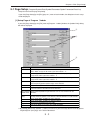
9-3 Print setup
9•18
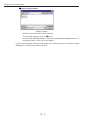
9-4 Print preview
9•20
9-5 Print
9•22
Table of Contents-6
Chapter 1 Introduction
Chapter 1
Introduction
JW-100SP is a ladder logic programming software that is capable of creating a program by ladder and
mnemonic of Sharp New Satellite JW Series PC (programmable controller), as well as setting up data
memory, system memory, symbol & comment, and the parameter.
Once created program or various data can be saved as file, or saved as document after having it printed.
By communicating with the JW Series PC, this software is capable of transferring the program or various
data as well as executing the monitor and debug functions.
This software works on Windows 95/98/Me or any other personal computer whose operating system is
Windows NT.
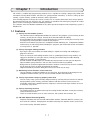
1-1 Features
(1) Variety of multi-window systems
・This software features independent windows for each item, like program, system memory or data
memory, so that you can change instantly to the desired window for editing.
・Several windows for one program can be opened at the same time so that you can easily create
the program by referring to other sections of the program.
・Since the list of contact-use(Data List), multipoints monitor and library are independent windows
and that they are most likely observed along the program, you will be able to refer and confirm
as many items as possible.
(2) Variety of program editing functions
・By using the full screen editor, the ladder editing is capable of creating and modifying the program at all times.
・There are variety of useful editing functions such as symbol input (like the relay number), cut/ copy/paste functions (by using the mouse), enlarging and contracting the ladder drawing,
adding line comment, jump and undo.
・Several methods of ladder inputs are available by using the mouse so that you can adjust the input method at your preference. You can also execute functions by keyboard.
・Being aware of a particular application instruction's number is not necessary since the available
list will help you select the input of application instruction.
・Sophisticated library functions allow you to create the similar circuit easily.
(3) Monitoring several windows at the same time
・You can monitor a number of windows at the same time. By registering the desired part in the
multipoints monitor window, you can use the monitor function more efficiently.
(4) Variety of parameter setups by property sheet form
・You can easily setup system memory and parameter by selecting the item from the list without
worrying about system memory, parameter address and data content. For this reason, the instruction manual of the product becomes compact, in concrete and simple fashion, to lessen
or avoid any setup errors.
(5) Variety of printing functions
・The software features an editor exclusively for creating header and footer so that you can freely
create the desired screen.
・There are useful functions such as cross reference, with symbol, with comment, etc.
(6) JW-50SP Upward Interchangeability
・Programs and data that were created under ladder software JW-50SP (IBM-PC versions) can
be used in this software. Also programs and data created by this software can be saved as file
that can be read by JW-50SP software.
1・1
Chapter 1 Introduction
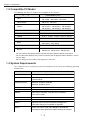
1-2 Compatible PC Model
The following JW series PC models are compatible to this software:
P
C
Control Module (CPU)
JW10
JW-1324K、JW-1424K、JW-1624K
JW-1342K、JW-1442K、JW-1642K
JW20,JW20H
JW-21CU、JW-22CU
JW30H
JW-31CUH、JW-32CUH、JW-33CUH
JW-31CUH1、JW-32CUH1、JW-32CUM1
JW-33CUH1、JW-33CUH2、JW-33CUH3
JW50/70/100
JW-50CU、JW-70CU、JW-100CU
JW50H/70H/100H
JW-50CUH、JW-70CUH、JW-100CUH
J-board
Z-311J、Z-312J、Z-313J、Z-511J、Z-512J
VME built-in controller
JW-32CV1、JW-32CV2
W100
ZW-1K0CU、ZW-1K1CU
ZW-1K2CU、ZW-1K3CU
W70H/100H
ZW-70CU、ZW-1HCU
W16/51
ZW-160CU
ZW-501CU、ZW-501CU2、ZW-501CU3
・You can connect your programmable controller to other optional modules than above.
・For the connection between the personal computer and the programmable controller, refer to
the next page.
・For the settings of each model, refer to page 5-5 and 5-46.
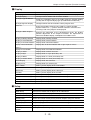
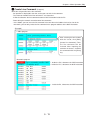
1-3 System Requirements
This software can be used by any personal computers that satisfy the following operating
environments:
System Requirements
Item
Personal computer
IBM PC personal computer or NEC PC-9800 series
CPU
More than 90MHz of Pentium (More than 200MHz of Pentium
recommended)
Operating system
Microsoft Windows 95/98/Me
Microsoft Windows NT4.0
Memory
More than 32M bytes (more than 64M bytes recommended)
Hard disk
30M bytes of the empty area
Monitor
More than SVGA (800×600 dots of the resolution,
more than16 color)
CD-ROM drive
One model
RS-232C port
More than 1 port
Mouse
Microsoft mouse or interchangeable pointing devise
(operations only by the keyboard are possible)
Printer
Printer that can be used under Windows 95/98/Me/NT
environment,when printing the ladder drawing, for example
1・2
Chapter 1 Introduction
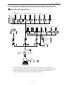
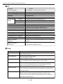
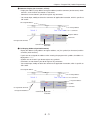
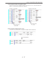
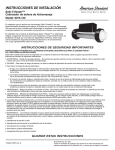
1-4 Connection between the Personal Computer and the PC
■ Basic System Organization
JW50/70/100
JW50H/70H/100H
control module
Network module
ZW-20CM
COMM
SD
RD
CD
LT
TEST
ERROR
FAULT
W16
W51, W100
W70H/100H
control module
SO
S1
S2
S3
S4
S5
S6
S7
Remote I/O
slave station module
ME-NET
COMM
SD
RD
CD
LT
TEST
COM.E
UNT.E
I/O bus
Serial interface
extension adapter module
Ethernet module
JW-108U
ZW-20RS
SO
S1
S2
S3
S4
S5
S6
S7
COMM
SD
RD
CD
LT
TEST
ERROR
FAULT
FL-net module
JW-50FL
JW-50CM
COMM
SD
RD
DC12V
DC
12V
10B5
TEST
SO
S1
S2
S3
S4
S5
S6
S7
LNK
TX
RX
DC12V
S0
S1
S2
S3
S4
S5
S6
S7
ERROR
FAULT
TEST
PER
HER
S0
S1
S2
S3
S4
S5
S6
S7
JW-20MN
P
R
O
G
R
A
M
M
E
R
P
R
O
G
R
A
M
M
E
R
89
67
MODE
23
MODE
STA.NO
×10
45
LINK FUNCTION
×1
×1
L1
LT
(ON)
→
01
MODE
STA.NO
×10
×1
LT
(ON)
→
EF
CD
AB
MODE
STA.NO
×10
LG
(ON)
→
10B5
10B5
LG
(ON)
→
LT
(ON)
→
LG
(ON)
→
L1
(ON)
→
L2
(ON)
→
L2
10B2
STATION NO.
10B-T
12VIN
(+)
(−)
FG
RESET
(+)
12VIN
(-)
STATION NO.
JW-50CU
JW-70CU
JW-100CU
JW-50CUH
JW-70CUH
JW-100CUH
ZW-20CM
ZW-30CM
JW-20CM
ZW-20CM2
JW-20MN
JW-2EA
ZW-20RS
JW-20RS
JW20/JW20H JW30H
Control module Control module
JW10
basic module
JW-50CM
JW-51CM
JW-10SU
Network module
ME-NET
module
JW-50FL
I/O bus
extension adapter
Ethernet module
FL-net module
JW-20FL5
JW-255CM
CMSDRD12V
T ERFT
LN TX RX 12V
456
456
456
23
456
23
456
23
78
901
78
901
78
901
23
901
456
901
78
901
78
T PE HE
S7 S6 S5 S4 S3 S2 S1 S0
S7S6S5S4S3S2S1S0
78
23
ZW-160CU
ZW-501CU3
ZW-1K0CU
ZW-1K1CU
ZW-1K2CU
ZW-1K3CU
ZW-70CU
ZW-1HCU
ME-NET
module
23
ON
ON
S
H
I
E
L
D
OFF
FG
RESET
JW-1324K/1342K
JW-1424K/1442K
JW-1624K/1642K
JW-21CU
JW-22CU
JW-22CM
JW-31CHU/H1
JW-32CUH/H1/M1
JW-33CUH/H1/H2/H3
JW-21MN
JW-32EA
JW-255CM
S
H
I
E
L
D
OFF
FG
RESET
JW-20FL5
JW-51FLT
J-board
Connection cable
Connection cable
Connection cable
JW-12KC(2m)
JW-22KC(2m)
JW-24KC(4m)
ZW-3KC (3m)
・CPU board
Z-311J,Z-312J,Z-313J
Z-511J,Z-512J
・Satellite net board
Z-335J
・ME-NET board
Z-334J
VME built-in controller
JW-32CV1
JW-32CV2
Communication adapter
JW-100SA
(9 pin connector)
Connection with
the IBM PC personal
computer
(25 pin connector)
Connection with
the NEC PC-9800 series
※ 1 ※ 2
Ladder logic
programming software
JW-100SP Personal computer
※ 1 You can only connect one IBM PC personal computer or one NEC PC-9800 series to the connector of your
personal computer (You cannot connect both 9pin connector of JW-100SA and 25 pin connector at the same time)
※ 2 Since the personal computer has the RS-232C port (half-pitched 14 pin), you need a conversion cable to
match the D-sub 25 pin (female) when connecting with the NEC PC9800 series.
1・3
Chapter 1 Introduction
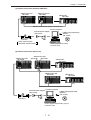
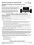
■ System Organization Using Communication
:Satellite net)
(1) Network connection (Standard:
JW50H/70H/100H
JW-20CM
JW50H/70H/100H
JW-20CM
JW20H/30H
JW-22CM
456
901
78
23
456
456
23
#01
23
#00
78
901
901
78
#77
Satellite net (data link function) maximum 64 stations, maximum 1km
Personal computer
Communication adapter
(JW-100SA)
Connection cable
(ZW-3KC)
When connected with
JW-22CM:JW-22KC/24KC
Ladder logic programming
software
(JW-100SP)
・Remote programming/monitor
・Parameter setup
:SUMINET-3200)
(2) Network connection (Standard:
Personal computer
Optical fiber cable
NSU NSU:Network service module
SUMINET-3200
maximum 126 stations
Line server
JW50H/70H/100H
ZW-30CM
JW50H/70H/100H
ZW-30CM
Personal computer
Communication adapter
(JW-100SA)
Ladder logic programming
software
(JW-100SP)
Connection cable
(ZW-3KC)
・Remote programming/monitor
・Parameter setup
1・4
Chapter 1 Introduction
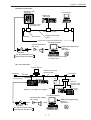
:ME-NET)
(3) Network connection (Standard:
JW50H/70H/100H
JW-20MN
JW50H/70H/100H
JW-20MN
JW20H/30H
JW-21MN
456
901
78
23
456
456
23
23
#01
#00
78
901
901
78
#77
ME-NET maximum 64 stations, maximum 1km
Personal computer
Communication adapter
(JW-100SA)
Connection cable
(ZW-3KC)
When connected with
JW-22CM: JW-22KC/24KC
Ladder logic programming
software
(JW-100SP)
・Remote programming /monitor
・Parameter setup
(4) Network connection (Expansion)
JW50H/70H/100H
JW-20CM
JW-20CM
JW50H/70H/100H
JW-20CM
JW20H/30H
JW-22CM
456
901
78
23
456
456
23
#01
23
#00
78
901
901
78
#77
#00
JW50H/70H/100H
JW-20CM
JW20H/30H
JW-22CM
456
901
78
23
456
23
456
78
901
901
78
23
#77
#01
Personal computer
Communication adapter
(JW-100SA)
Ladder logic programming
software
(JW-100SP)
Connection cable
(ZW-3KC)
・Remote programming/monitor (2 layers)
・Parameter setup
1・5
Chapter 1 Introduction
(5) Remote I/O connection
JW50H/70H/100H
JW-20CM
JW-20RS
JW-20RS
#01
#00
JW-20RS
#02
#77
Remote I/O maximum 63 stations, maximum 1km
Personal computer
Ladder logic programming
software
(JW-100SP)
Communication adapter
(JW-100SA)
Connection cable
(ZW-3KC)
・Remote programming /monitor
・Parameter setup
(6) Computer link connection (RS-485 connection)
Personal computer
Ladder logic programming
software
(JW-100SP)
JW50H/70H/100H JW50H/70H/100H
JW-10CM
JW-10CM
RS-232C/422 converter
Z-101HE
RS-232C
(less than 15m)
#01
JW20H/30H
JW-21CM
#02
RS-485 (cable maximum length:less than1km)
(7) Computer link connection (RS-232C connection)
Personal computer
Ladder logic programming
software
JW70H/100H
(JW-100SP)
Communication port
RS-232C (less than 15m)
1・6
#37
Chapter 1 Introduction
(8) Ethernet connection
JW50H/70H/100H
JW-50CM
Host computer
JW20H/30H
JW-255CM
J W -2 5 5 C M
CM SD RD12V
T ER FT
S7 S6 S5 S4 S3 S2 S1 S0
ON
S
H
I
E
L
D
OFF
FG
Transceiver cable
(maximum 50m)
Maximum 100 stations
Transceiver
Terminator
10BASE5 coaxial cable
(yellow)
Coaxial cable segment (maximum 500m)
Personal computer
Communication adapter
(JW-100SA)
Ladder logic programming
software
(JW-100SP)
Connection cable
(ZW-3KC)
Use JW-22KC/24KC when
connecting to JW-255CM
・Remote programming /monitor
・Parameter setup
(9) L-net connection
Personal computer
Terminator
10BASE5 coaxial cable
(maximum 500m)
Transceiver
FL-net
Transceiver cable
JW50H/70H
(maximum 50m) JW50H/70H
/100H
NC
JW-20H/30H
JW20H/30H
Hub
10BASE-T
twisted pair cable
(maximum 100m)
JW-20FL5
JW-20FL5
JW-50FL
JW20H/30H
J-board
OFF
1
2
Maximum 100 nodes per segment
JW50H/70H
JW-50H/70H
/100H
/100H
JW-20FLT
Z-336J
JW-50FL
Personal computer
Communication adapter
(JW-100SA)
Connection cable
(ZW-3KC)
Use JW-22KC/24KC when
connecting to JW-20FL5/T
・ Parameter setup
1・7
Ladder logic programming
software
(JW-100SP)
Chapter 1 Introduction
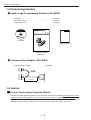
1-5 Product Organization
■ Ladder Logic Programming Software (JW-100SP)
CD-ROM ・・・・・・・・・・・・・・・・・・・・・・・・・・・・・・・・・・・・・・ 1 (quantity)
Instruction manual ・・・・・・・・・・・・・・・・・・・・・・・・・・・・・・ 1 (quantity)
Registration card ・・・・・・・・・・・・・・・・・・・・・・・・・・・・・・・ 1 (quantity)
初 版
1998年2月作成
®
JW-100SP
ラダー設計支援ソフト
ラダー設計支援ソフト
For Windows 95 / NT
形名
JW-100SP
取扱説明書
Copyright 1998 SHARP MANUFACTURING SYSTEMS CORPORATION.
All rights reser ve d.
Windows は、米国マイクロソフト社の米国およびその他の国における登録商標です。
CD-ROM
Registration card
Instruction manual
(Japanese)
■ Communication Adapter (JW-100SA)
Communication adapter ・・・・・・・・・・・・・・・ 1 (quantity)
80 mm
140 mm
1-6 Caution
■ On-line Caution upon Using the Monitor
When the personal computer and the PC are connected, use the on-line monitor after transferring the PC
program to the personal computer, or after transferring the personal computer program to the PC. If you
don't transfer the programs, you won't be able to have the correct calculation at the ladder monitor/
mnemonic monitor since the program of PC and personal computer may not be the same.
1・8
Chapter 1 Introduction
1-7 Conventions Used in This Manual
■ Display of Menu, Command, Dialog Box
Display Meaning
[
]
・Displayhe menu name, command name and button name in [
].
Example) [File] menu, [New] command, [OK] button
・Display the the name of the title bar of the dialog box displayed in [
Example) [Open File] dialog box
[
]-[
]
].
・Show the layers of menu,command.
Example) select [File]-[New].
(It means that [New] command is selected from the [file] menu)
Example) select [PC]-[PC Transfer]-[Write].
(It means that [PC Transfer] menu is selected from the [PC] menu, and
in addition, it means to select the [Write] command)
■ Display of Mouse Operations
Display Meaning
Click
・Press the mouse button once and release the button right after.
・Among the two buttons of the mouse, when only“click”is displayed, it is to
press the left button, and when“right click”is displayed, it means to press the
right button.
Double click
・Means to press the left button of the mouse quickly twice.
Drag
・Means to keep pressing the left button, then release the button after moving it to the desired position.
■ Display of Key Operations
Display Meaning
[
] ・Keys are displayed in [
].
Example) [Enter] key, [S] key
[
]+[
] ・ [+] means to press a number of keys at the same time.
Example) [Ctrl]+[S] key
Directional key ・The general name of [→] [←] [↑] [↓] keys
1・9
Chapter 2 Setup
Chapter 2 Setup
“Setup”
means the condition of the application/software that is ready to be operated by installing it into to the
personal computer. In this chapter, the setup order of the ladder logic programming software・JW-100SP is
explained.
JW-100SP operates under Windows 95/98/Me/NT, but the setup order of this software is explained for
Windows 98 environment.
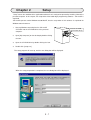
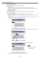
1. Start-up Windows 98, and place the JW-100SP
CD-ROM into the CD-ROM drive of the personal
computer.
2. Open [My Computer] on the desktop by double clicking
the icon.
3. Open the CD-ROM drive by double clicking the icon.
4. Double click [setup.exe].
The setup program will start-up, and the next dialog box will be displayed.
When the setup preparation is completed, the next dialog box will be displayed.
2・1
Place the CD-ROM,
with the label side up.
Chapter 2 Setup
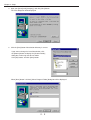
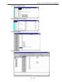
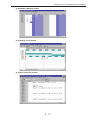
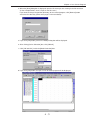
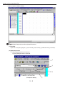
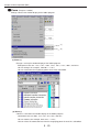
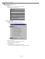
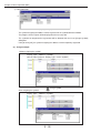
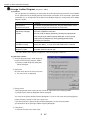
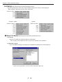
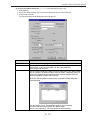
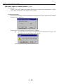
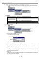
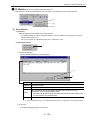
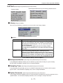
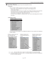
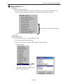
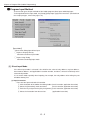
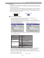
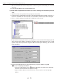
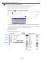
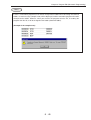
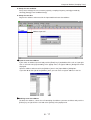
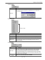
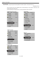
5.Input your [Name] and [Company], and click [Next] button.
The next dialog box will be displayed.
6.Click the [Next] button if destination directory is correct.
If you want to change the install destination, click
the [Browse] button to display the [Choose Folder]
dialog box, and assign the drive or folder.
Click [OK] button, and click [Next] button.
When [Next] button is clicked, [Select Program Folder] dialog box will be displayed.
2・2
Chapter 2 Setup
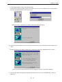
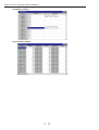
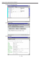
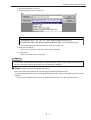
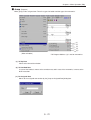
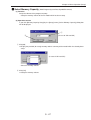
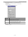
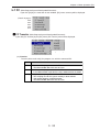
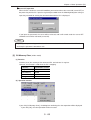
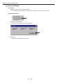
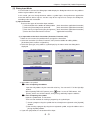
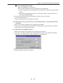
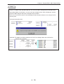
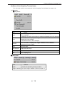
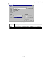
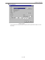
7.If the program folder is correct, click [Next] button.
If you want to change the folder, input the new folder name, or select the folder from the Existing Folder
list.Then, click [Next] button to start up the setup.
When the setup is completed, the following dialog box will be displayed.
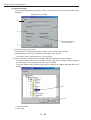
8.If you click [Finish] button, the same screen at the moment of the setup is displayed, and it completes the
setup.
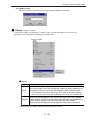
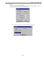
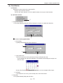
(Caution) Sometimes,the following dialog box is displayed instead of the dialog box which is shown
abobe.
In this case,click [Finish] button,and restart the computer.Then,the setup will be complete.
9.To start JW-100SP, click [Programs]-[Sms]-[JW100SP] on the start menu of Windows98. (Refer to
Chapter 3)
2・3
Chapter 3 Basic Operation (Starting-up and Quitting)
Chapter 3
Basic Operation
3-1 Starting-up and Quitting
How to start or quit JW-100SP will be explained.
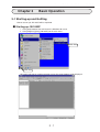
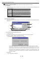
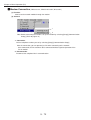
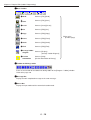
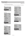
■ Starting-up JW-100SP
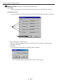
1.Click [Start] button of the task bar on the Windows 98 screen.
2.Click [Programs]-[Sms]-[JW100SP] on the start menu.
Click here
Click here
JW-100SP will start-up, and the principle screen (the main window) will be displayed.
3・1
Chapter 3 Basic Operation (Starting-up and Quitting)
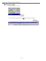
■ Quitting JW-100SP
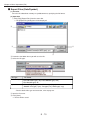
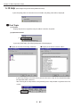
1.Click [File]-[Quit] on the menu bar.
Click here
You can also quit the operation by clicking [X] at the upper-right of the window.
Click here
3・2
Chapter 3 Basic Operation (List of files about JW-100SP)
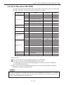
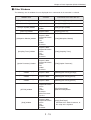
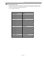
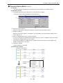
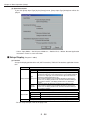
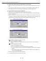
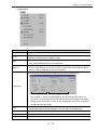
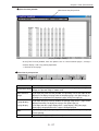
3-2 List of files about JW-100SP
JW-100SP opens program-related files and a variety of data at a time so that you can create or edit
files about JW-100SP. The list of JW-100SP related files is as follows:
Classification
Extension
Data memory related
Parameter related
Symbol /comment
related
Optional parameters
related
Data compatibility with
JW-50SP
File type *1
*.pgm
Program
Yes
●
*.lad
Ladder screen information
No
●
*.la2
Ladder screen information
(in case of more than 31.5K words)
No
●
*.ist
Mnemonic screen information
No
●
*.is2
Mnemonic screen information
(in case of more than 31.5K words)
No
●
*.lcm
Line comment
No
●
*.sys
System memory
Yes
●
*.dat
Data memory
Yes
●
*.dfi
Data memory,file memory
No
■
*.fil
File memory
Yes
■
*.prm
Parameter (JW20H/30H)
Yes
●
*.syc
Symbol/comment
No
●
*.sye
Symbol/comment
Yes (V5.0 or later)
■
Program related
System memory
related
Contents
*.sym
Symbol/comment
Yes (V4.0A or previous)
■
*.txt
Text
No
■
*.2rm
Remote I/O master station parameter
Yes
▲
*.2rs
Remote I/O slave station parameter
Yes
▲
*.2dm
Data link master station parameter
Yes
▲
*.2ds
Data link slave station parameter
Yes
▲
*.mem
ME-NET master station parameter
Yes
▲
*.mes
ME-NET slave station parameter
Yes
▲
*.3cm
SUMINET parameter
Yes
▲
*.2rd
Other parameter
Yes
▲
Multipoints monitor
related
*.mon
Multipoints monitor
(registered address)
No
▲
Sampling trace related
*.smp
Sampling trace
No
▲
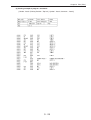
*1 About file type
●: Files you can save by selecting [File]-[Save]/[Save as] in JW-100SP.
■: Files you can save by selecting [File]-[Export Files] in JW-100SP.
You cannot open these files by selecting [File]-[Open]. Insert them into the file in operation
by selecting [File]-[Import Files].
▲: Files you can save by selecting [File]-[Save]/[Save as] in the window of [Option parameters],
[Multipoints monitor], or [Sampling trace].
Note
JW-100SP can read the file that carries the extension, "Data compatibility with JW-50SP: Yes," created
and saved by JW-50SP. To read JW-100SP files by JW-50SP, you need to save data in the file by the
extension, "Data compatibility with JW-50SP: Yes."
3・3
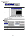
Chapter 3 Basic Operation (Screen Configuration)
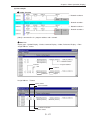
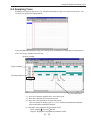
3-3 Screen Configuration
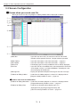
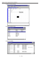
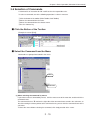
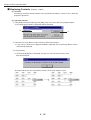
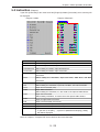
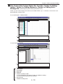
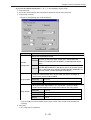
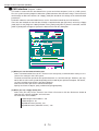
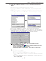
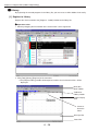
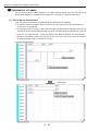
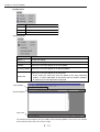
■ Screen when you create new file
When you create new file, the [Program: Ladder] windows will be displayed as follows:
①
②
⑦
③
Tab
⑤
⑥
④
①Menu Bar ②Main Toolbar
③Sub Toolbar ④Status Bar
⑤Tree Bar
⑥Message Bar
⑦Toolbar for Editing Ladder
:If you click the item name, the menu that calls for JW-100SP
functions will be opened. Refer to“Chapter 5 Menu Operation”
.
:If you click the button, it calls for that function. → page 3-5
:If you click the button, it calls for that function. → page 3-6
:Data display type or running condition of the PC will be displayed.
:If you click the tab, the window of the selected tab will be active.For
each window, refer to“3-4 Kinds of Windows”
According to a tab,
the tree display will be different.
:Display the operation-completed massage or the error message.
:Used when the ladder program is created. It is displayed when
[Program:Ladder] window is active.→ page 3-8
●Toolbars other than described above
⑧Toolbar for Editing Mnemonic :Used when mnemonic program is created. It is displayed when
⑨Toolbar for Editing Data
[Program:Mnemonic] window is active.→ page 3-9
:Used for the selection of data display types. It is
displayed when [System],[Data],[Parameter] and
[Other Parameter] windows are active.→ page 3-10
3・4
Chapter 3 Basic Operation (Screen Configration)
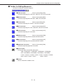
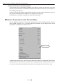
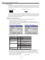
■ Main Toolbar
PC model name Program memory capacity Project name
◎
Same as [File]-[New]
◎New Create a new file (program, system memory, data memory, symbol/comment,
or parameter).
◎
Same as [File]-[Open]
◎Open
Open the existing file (program, system memory, data memory, symbol/comment,
parameter).
◎
Same as [File]-[Save]
◎Save Save the set of the files in operation (program, system memory, data memory, symbol/
comment, or parameter) under the current file names.
◎
Same as [Edit]-[Cut]
◎Cut Cut the selected area and saves it for the moment.
◎
Same as [Edit]-[Copy]
◎Copy Save the selected area and saves it for the moment.
◎
Same as [Edit]-[Paste]
◎Paste Paste the data that was cut or copied onto the position of the cursor.
◎Image Copy Same as [Edit]-[Image Copy]
Temporarily keep in the clipboard the selected area you are editing in the ladder program
window as an image data.
◎
Same as [Edit]-[Undo]
◎Undo It brings back the previous state of the operation.
◎
Same as [Display]-[Change Display]
◎Change Display
Change the window of the ladder and mnemonic.
◎
Same as [Display]-[Changes Segment Display]
◎Change Segment File
Change between file 8 and file 9 of the program area.
◎
◎Program Check
Execute the program check.
Same as [Edit]-[Program Check]
◎
Same as [Display]-[Arrange Ladder Diagram]
◎Arrange Ladder Diagram
Execute the connection of the disconnected circuit, adjustment of the display
position,adjustment of the MCS/JCS condition display, and optimize the ladder circuit.
◎
Same as [File]-[Print]
◎Print Print contents of the active window (ladder program, mnemonic program, system memory,
data memory, symbol /comment, parameter).
3・5
Chapter 3 Basic Operation (Screen Configuration)
◎Print Preview Display the printing image.
Same as [File]-[Print Preview] ◎Version
Same as [Help]-[Version Data (MMVIEW)]
Display the version of JW-100SP.
■ Sub Toolbar
Search history Ladder display magnifying power ◎
Same as [Edit]-[Find]
◎Find Find the mnemonic, address (relay, register etc..), character line (symbol, comment etc..).
◎
Same as [Edit]-[Find Previous]
◎Find Previous Find the mnemonic, address, character line that are selected from the find
character summary from the cursor position to the backward direction.
Same as [Edit]-[Find Next]
◎Find Next Find the mnemonic, address, character line that are selected from the find
character summary from the cursor position to the forward direction.
◎
Same as [Edit]-[Zoom]-[Zoom(−)]
◎Reduce Display Contract the program (ladder) display.
◎
Same as [Edit]-[Zoom]-[Zoom(+)]
◎Expand Display Enlarge the program (ladder) display.
◎Normal Display
◎
Same as [Display]-[Display Type]-[Nomal Display Type]
Display the ladder instruction only by its address in the ladder program window.
◎
Same as [Display]-[Display Type]-[Symbol Display Type]
◎Symbol Display
Display the ladder instruction only by its symbol in the ladder program window.
◎
◎Display of Comment (8 characters, 4 lines)
Same as [Display]-[Display Type]-[Comment Display Type(8C4R)]
Display the ladder instruction by its address and comment in the ladder program window.
◎
◎Display of Comment (16 characters, 2 lines)
Same as [Display]-[Display Type]-[Comment Display Type(16C2R)]
Display the ladder instruction by its address and comment in the ladder program window.
◎
Same as [Display]-[Display Type]-[Full Display Type]
◎Full Display Display the ladder instruction by its address, symbol and comment in the ladder program
window.
◎
Same as [Display]-[folding]-[Off]
◎One line View
Display each line in the ladder program unfolded in one line in the ladder program window.
3・6
Chapter 3 Basic Operation (Screen Configration)
◎Word-wrap View ◎
Same as [Display]-[folding]-[On]
Display each program line, which is longer than the window's width, folded in the ladder
program window.
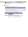
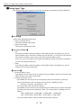
■ Message Bar
Display the operation completed message or the error message.
If you click the right side of the mouse on the message bar, the following menu will be displayed,
and you can erase the message if you select the command.
Clear All
:Erase all messages inside the message bar.
Clear One Column:Erase the message at the cursor row.
3・7
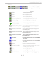
Chapter 3 Basic Operation (Screen Configuration)
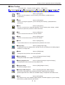
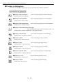
■ Toolbar for Editing Ladder
Use when creating ladder program.
◎A Contact ◎
Used when inputting A contact.
Same as [Instruction]-[A contact]
◎
Same as [Instruction]-[B contact]
◎B Contact Used when inputting B contact.
◎
Same as [Instruction]-[Vertical Line]
◎Vertical Line Used when inputting vertical line.
◎
Same as [Instruction]-[Horizontal Line]
◎Horizontal Line Used when inputting horizontal line.
◎OUT Instruction
◎
Same as [Instruction]-[OUT]
Used when inputting OUT instruction (coil).
◎
Same as [Instruction]-[TMR]
◎TMR Instruction
Used when inputting TMR instruction.
◎
Same as [Instruction]-[CNT]
◎CNT Instruction
Used when inputting CNT instruction.
◎
Same as [Instruction]-[FUN]
◎Application Instruction
Used when inputting application instruction.
◎F-45 Instruction ◎
Same as [Instruction]-[F45]
Used when inputting F-45 instruction (differential OFF).
◎
Same as [Instruction]-[F44]
◎F-44 Instruction Used when inputting F-44 instruction (differential ON).
◎
Same as [Instruction]-[F43]
◎F-43 Instruction Used when inputting F-43 instruction (revert bit).
◎Widen/Narrow Frame
Used when you need to extend the frame downward in result of the added OR circuit by,
for example, CNT instruction or multiple inputs of application instruction (F-60 etc..).
◎Eraser
◎
Used when erasing the circuit (cell unit).
◎
◎Convert
Convert the ladder circuit to mnemonic.
◎
◎Change Cursor Type
In case of direct input mode, it changes the instruction cursor to the mouse cursor with
arrow.
3・8
Chapter 3 Basic Operation (Screen Configration)
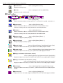
■ Toolbar for Editing Mnemonic
Use when creating the mnemonic program.
◎
Same as [Instruction]-[STR]
◎STR Instruction Used when inputting STR, STR NOT, AND STR, OR STR instruction.
◎
Same as [Instruction]-[AND]
◎AND Instruction Used when inputting AND, AND NOT, AND STR instruction.
◎
Same as [Instruction]-[OR]
◎OR Instruction Used when inputting OR, OR NOT, OR STR instruction.
◎
Same as [Instruction]-[NOT]
◎NOT Instruction Used when inputting STR NOT, AND NOT, OR NOT instruction.
◎
Same as [Instruction]-[OUT]
◎OUT Instruction Used when inputting OUT instruction.
◎
Same as [Instruction]-[TMR]
◎TMR Instruction Used when inputting TMR instruction and TMR contact.
◎
Same as [Instruction]-[CNT]
◎CNT Instruction
Used when inputting CNT instruction and CNT contact.
◎
Same as [Instruction]-[FUN]
◎Application Instruction Used when inputting application instruction.
◎
◎Convert Code
Change the kinds of instruction and register.
・TMR→DTMR(BCD)→DTMR(BIN)→UTMR(BCD)→UTMR(BIN)
・CNT→DCNT(BCD)→DCNT(BIN)→UCNT(BCD)→UCNT(BIN)
・F-XXX→F-XXXw→F-XXXd→FcXXX→FxXXX→FcXXXw→FxXXXw
・]0000→b0000→09000→19000→ ・・・・ →99000→E0000
◎
◎Convert
Convert mnemonic to ladder circuit.
3・9
Chapter 3 Basic Operation (Screen Configuration)
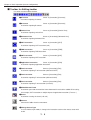
■ Toolbar for Editing Data
Used when selecting data display types of system memory, data memory, parameter.
◎
◎Displays in Binary Notation
Displays data in binary notation
Same as [Display]-[Display in Binary Notation]
◎
◎Displays in Octal Notation
Displays data in octal notation.
Same as [Display]-[Display in Octal Notation]
◎
◎Displays in Decimal Notation
Displays data in decimal notation.
Same as [Display]-[Display in Decimal Notation]
◎
◎Displays in Decimal Notation (with sign)
Same as [Display]-[Display in Decimal Notation (with +/-)]
Displays data in decimal notation with a sign of plus or minus.
Same as [Display]-[Display in Hex Notation]
◎
◎Displays in Hex Notation
Displays data in hexadecimal notation.
◎
◎Displays in ASCII
Displays data in ASCII character.
Same as [Display]-[Display in ASCII]
◎
Same as [Display]-[Display in Byte]
◎Displays in Byte
Displays data in 1 byte (8 bit data).
◎
Same as [Display]-[Display in Word]
◎Displays in Word
Displays data in 1 word (16 bit data).
◎
Same as [Display]-[Display in Double Word]
◎Displays in Double Word
Displays data in 2 word (32 bit data).
◎
◎Displays as a List
Displays data in summary list.
Same as [Display]-[Display in List]
◎
◎Displays in Detail
Displays data with comment.
Same as [Display]-[Detail Display]
3・10
Chapter 3 Basic Operation (Kinds of Windows)
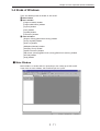
3-4 Kinds of Windows
There are following kinds of window in JW-100SP.
① Main window
② Basic window
[Program:Ladder] window
[Program:Mnemonic] window
[System] window
[Data] window
[Symbol] window
[Parameter] window
③ Other windows
[Register Library]/[Read from Library] window
[Assign Symbol] window
[Data List] window
[Multipoints Monitor] window
[Sampling Trace] window
[Option Parameter] window
[Edit Circuit (Change)]/[Edit Circuit (Insert)]/[Edit Circuit (Delete)] window
[HF Edit] window
[Help] window
■ Main Window
Main window is a window which is opened up at the starting-up of JW-100SP.
If you close the main window, JW-100SP will quit the system.
3・11
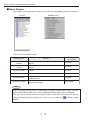
Chapter 3 Basic Operation (Kinds of Windows)
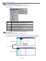
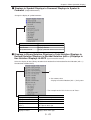
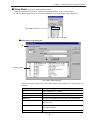
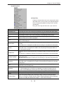
■ Basic Window
Basic window can be selected by clicking on the tree bar, or by the [Window] menu of the menu bar.
Tree Bar [Window] menu
There are six basic windows below:
Window Name
[Program:Ladder]
window
[Program:Mnemonic]
window
[System] window
[Data] window
[Symbol] window
[Parameter] window
Contents
Possible PC models
for selection
Create, save, monitor, print , etc... the ladder
program
All models
Create, save, monitor, print , etc...of the mnemonic
program
All models
Setup, save, monitor, print, etc... of the system
memory
All models
Setup, save, monitor, print, etc... of the data memory All models
Setup, save, monitor, print, etc... of the
symbol/comment
All models
Parameter setup, save, monitor, print, etc... of the
special/option module
JW20,JW30H
Note
If you click [Program] tab of the Tree Bar,[Program:Ladder] window will be active. To make
[Program:Mnemonic] window active, select [Program:Mnemonic] window from the [Window].
Also, you can interchange between [Program:Ladder] and [Program:Mnemonic] windows by
selecting [Display]-[Change Display] of the menu bar, or by clicking the
button of the Main
Toolbar.
3・12
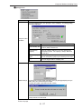
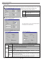
Chapter 3 Basic Operation (Kinds of Windows)
(1) [Program:Ladder] window
(2) [Program:Mnemonic] window
(3) [System] window
(4) [Data] window
3・13
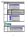
Chapter 3 Basic Operation (Kinds of Windows)
(5) [Symbol] window
(6) [Parameter] window
3・14
Chapter 3 Basic Operation (Kinds of Windows)
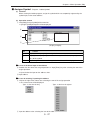
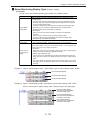
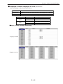
■ Other Windows
The followings are the windows that are displayed when "command" of the menu bar is selected.
Window name
Possible windows for
selection
Commands of the menu bar etc...
[Register Library] window
Program:Ladder
[Tool]-[Library]-[Register]
[Read from Library] window
Program:Ladder
[Tool]-[Library]-[Read]
[Assigns Symbol] window
Program:Ladder
Symbol
[Edit]-[Assign Symbol]
[Data List] window
Program:ladder
[Display]-[Data List]
[Multipoints Monitor] window
Main
Program:Ladder
Program:Mnemonic
System
Data
Symbol
Parameter
[Tool]-[Multipoints Monitor]
[Sampling Trace] window
Main
Program:Ladder
Program:Mnemonic
System
Data
Symbol
Parameter
[Tool]-[Sampling Trace]
[Option Parameter] window
Main
Program:Ladder
Program:Mnemonic
System
Data
Symbol
Parameter
[Tool]-[Option Parameter]
[Edit Circuit (Change)]
window
Program:Ladder
[Monitor]-[Edit Circuit]-[Change]
[Edit Circuit (Insent)]
window
Program:Ladder
[Monitor]-[Edit Circuit]-[Insent]
[Edit Circuit (Delete)]
window
Program:Ladder
[Monitor]-[Edit Circuit]-[Delete]
[HF Edit] window
Program:Ladder
Program:Mnemonic
System
Data
Symbol
Parameter
Option Parameter
Data List
[File]-[Page Setup][Boot HF Editor] button
[Help] window
Main
Program:Ladder
Program:Mnemonic
System
Data
Symbol
Parameter
[Help]-[Find Topic]Selection of the table of contents, or
the setup of the keyword.
3・15
Chapter 3 Basic Operation (Kinds of Windows)
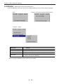
(1) [Register Library] window
(2) [Assign Symbol] window
(3) [Data List] window
3・16
Chapter 3 Basic Operation (Kinds of Windows)
(4) [Multipoints Monitor] window
(5) [Sampling Trace] window
(6) [Option Parameter] window
3・17
Chapter 3 Basic Operation (Kinds of Windows)
(7) [Edit Circuit (Change)] window
(8) [HF Edit] window
(9) [Help] window
3・18
Chapter 3 Basic Operation (Selection of Commands)
3-5 Selection of Commands
A command is an instruction for JW-100SP to take the responsible tasks.
To select a command, one of the following operations is taken in measure.
①Click the button of the toolbar (Main Toolbar, Sub Toolbar)
②Select the command from the menu.
③Select the command from the shortcut menu. ④Use the shortcut key.
■ Click the Button of the Toolbar
(Example:In case of [Find])
Click here
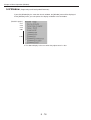
■ Select the Command from the Menu
Commands are grouped and stored in the menu.
Menu
Sub menu
▼
(1) When selecting the command by mouse
If you want to select a command by mouse, click the menu name of the menu bar, and then click the
command name.
The command that has
mark on the right side of the command name contains the sub menu, so
that after moving the mouse pointer to the command name, you can click the command name of the
sub menu.
To close the menu without selecting the command, click simply outside of the menu.
3・19
Chapter 3 Basic Operation (Selection of Commands)
(2) When selecting the command by keyboard
It you want to select a command by keyboard, press [Alt] key to make the menu bar active, and
press the key that matches the underlined characters just after the menu name. (for example, in
case of [Edit], press [E] key)
Then press the key that matches the underlined characters just after the command name, or the key
that matches the numbers (for example, in case of [Find], press [S] key)
By closing the menu without selecting a command, press [Esc] key.
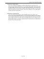
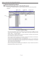
■ Select a Command from the Shortcut Menu
You can display the shortcut menu when the mouse pointer is on the window (Program, System,
Data, Symbol, Parameter, etc...) or the Message Bar. Commands that are objects of the current
operations are included in the shortcut menu.
Shortcut menu
To display the shortcut menu, move the mouse pointer on the objects of the operation, and click the
right button of the mouse. When the shortcut menu is displayed, click the command name. To close
the shortcut menu without selecting the command, click simply outside of the shortcut menu.
3・20
Chapter 3 Basic Operation (Selection of Commands)
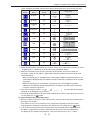
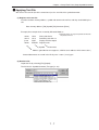
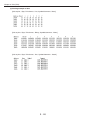
■ Use the Shortcut Key
Among commands, there are commands that can be selected by pressing the shortcut key which is
displayed at the right side of the command name when the menu is opened. For example, to create
a new file, press [N] key with [Ctrl] key being pressed.
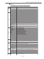
There are following shortcut keys.
Shortcut keys Function
[Ctrl] + [N] key
[Ctrl] + [O] key
[Ctrl] + [S] key
[Ctrl] + [P] key
[Ctrl] + [X] key
[Ctrl] + [C] key
[Ctrl] + [V] key
[Ctrl] + [Z] key
[Ctrl] + [F] key
[Ctrl] + [A] key
[Ctrl] + [I] key
[Ctrl] + [L] key
[Ctrl] + [H] key
[Ctrl] + [D] key
[Ctrl] + [G] key
[Ctrl] + [T] key
[Ctrl] + [B] key
[Ctrl] + [J] key
[Ctrl] + [M] key
[Ctrl] + [U] key
[Ctrl] + [K] key
[Shift] + [PageUp] key
[Shift] + [PageDown] key
New
Open
Save
Print
Cut
Copy
Paste
Undo
Find
Find Coil
Insert Cell
Insert Row
Delete Cell
Delete Row
Create Line Comment
Jumps to Top Row
Jumps to Unedited Row
Jumps to Assigned Row
Jumps to Address Mark
Jumps to Program Address
Program Check
Find Previous
Find Next
3・21
Chapter 3 Basic Operation (Function Summary)
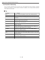
3-6 Function Summary
Here, the function (command) of the menu bar of the main window and the basic window is explained.
Depends of the window, the
“yes/no”
functions are different. In addition, refer to
“Chapter 5 Menu Operation”
for the detail of each function.
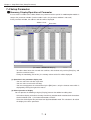
■ File
Command
Function
New
Create a new basic file (program, system, data, symbol, parameter).
Open
Open the existing basic file (program, system, data, symbol, parameter).
Close
Close the basic file you are editing (program, system, data, symbol,
parameter).
Save
Save the basic file you are editing (program, system, data, symbol,
parameter) under the current file name.
Save As
Save the basic file you are editing (program, system, data, symbol,
parameter) under a new file name.
Import Files
Import the data memory or symbol/comment file created with a ladder
software, JW-50SP.
Export Files
Export the data memory or symbol/comment file you are editing in the
file format of a ladder software such as JW-50SP.
FD Verify
Compare the existing files with files in the active window (program,
system, data, symbol, parameter).
Page Setup
Setup the format of the page that is to be printed.
Print
Print the contents of the active window (ladder, mnemonic, system, data,
symbol, parameter).
Print Preview
Display the image of the files in the active window (ladder, mnemonic,
system, data, symbol, parameter).
Printer Setup
Setup“select/connection”of the printer.
Quit
Quit the system of JW-100SP.
3・22
Chapter 3 Basic Operation (Function Summary)
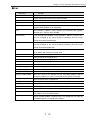
■ Edit
Command
Function
Undo
It brings back the previous state of the operation.
Cut
Cut the selected area and saves it for the moment.
Copy
Save the selected area and saves it for the moment.
Paste
Paste the data that was cut or copied onto the position of the cursor.
Image Copy
Temporarily keep in the clipboard the selected area you are editing in the
program ladder window as an image data.
Find
Find mnemonic, address (relay, register etc..),character line (symbol,
comment etc..) from the active window.
Find Previous
In the selected active window, search mnemonic, address, character line
(that are assigned in the search character summary) from the cursor
position to the backward direction.
Find Next
In the selected active window, search mnemonic, address, character line
(that are assigned in the search character summary) from the cursor
position to the forward direction.
Find Coil
Search the output (coil) in which the relay address of the cursor position
(on A contact and B contact) is being used.
Insert Cell
Insert the cell in the assigned area.
Insert Row
Insert the row in the assigned area.
Delete Cell
Delete the cell in the assigned area.
Delete Row
Delete the row in the assigned area.
Create Line Comment
Input the comment in the assigned line.
Zoom [Zoom(+)]
Enlarge the display of the ladder program
Zoom [Zoom(−)]
Contract the display of the ladder program
Jump [To Top Row]
Move the cursor to the front row of the window.
Jump [To Unedited Row]
Move the cursor to the unwritten row for the ladder program, and for
mnemonic program, the cursor is moved to the row of NOP instruction.
Jump [To Assigned Row]
Move the cursor to the assigned row.
Jump [To Address Mark]
Move the cursor to the line of address mark which has been setup.
Jump [To Program Address] Move the cursor to the specified address line.
Program Check
Check the grammar and format of the ladder program.
Converts Data in Batch
Convert the address number such as relay or register in batch.
Replacement NO and NC Replace A contact with B contact, or vice versa, at the point equal to the
relay address of the specified contact.
Assigns Symbol
[Assign Symbol] window is opened. Here, the symbol that was input by
the ladder program is assigned to the address.
3・23
Chapter 3 Basic Operation (Function Summary)
■ Instruction
Command
Function
A Contact
Used for inputting A contact when editing ladder.
B Contact
Used for inputting B contact when editing ladder.
Horizontal Line
Used for inputting horizontal line when editing ladder.
Vertical Line
Used for inputting vertical line when editing ladder.
STR
Used for inputting STR, STR NOT, AND STR, OR STR when editing
mnemonic.
NOT
Used for inputting STR NOT, AND NOT, OR NOT when editing mnemonic.
AND
Used for inputting AND, AND NOT, AND STR when editing mnemonic.
OR
Used for inputting OR, OR NOT, OR STR when editing mnemonic.
OUT
Used for inputting OUT instruction(coil)
TMR
Used for inputting TMR instruction.
Used also for inputting TMR contact when editing mnemonic.
CNT
Used for inputting CNT instruction.
Used also for inputting CNT contact when editing mnemonic.
FUN
Used for inputting application instruction.
F43
Used for inputting F-43 instruction(revert bit).
F44
Used for inputting F-44 instruction(differential ON).
F45
Used for inputting F-45 instruction(differential OFF).
F-20(MD)
Used for inputting F-20 instruction(MD).
■ Monitor
Command
Function
Start Monitoring
Start the monitoring.
Stop Monitoring
Stop the monitoring.
I/O Forced Processing
ON/OFF the relay of the PC with force.
Edit Circuit [Change]
Change the ladder circuit of the PC in the monitoring.
Edit Circuit [Insert]
Insert the ladder circuit of the PC in the monitoring.
Edit Circuit [Delete]
Delete the ladder circuit of the PC in the monitoring.
3・24
Chapter 3 Basic Operation (Function Summary)
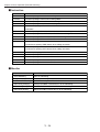
■ Display
Command
Function
Display Type
Select the display of the address/symbol inside the ladder program.
Change Display
Change between ladder and mnemonic window.
Changes Type of Monitor
Assign the monitoring type of the ladder program (notation display
yes/no),and the register display type (octal/decimal/hexadecimal)
Change Segment Display
Change between the file 8 and file 9 of the program area.
Data List
[Data List] window is opened. Here, address (contact number,
register number etc...), symbol, comment and cross reference that
are being used in the program are displayed.
Arrange Ladder Diagram
Execute the connection of the disconnected circuit, the display
position adjustment of the output instruction, the adjustment of
MCS/JCS condition display, and optimize the ladder circuit.
Display in Binary Notation
Displays data in binary notation.
Display in Octal Notation
Displays data in octal notation.
Display in Decimal Notation
Displays data in decimal notation.
Display in Decimal Notation
Display data in decimal notation with a sign of plus or minus.
(with +/-)
Displays in Hex Notation
Displays data in hexadecimal notation.
Display in ASCII
Displays data in ASCII character.
Display in Byte
Displays data in 1 byte (8 bit data) unit.
Display in Word
Displays data in 1 word (16 bit data) unit.
Display in Double Word
Displays data in 2 word (32 bit data) unit.
Detail Display
Displays data with comment.
Display in List
Displays data in a summary list.
Main Toolbar
Select“yes/no”display of the main toolbar.
Sub Toolbar
Select“yes/no”display of the sub toolbar.
Status Bar
Select“yes/no”display of the status bar.
Tree Bar
Select“yes/no”display of the tree bar.
Toolbar for Edit Data (L)
Select“yes/no”display of the toolbar for editing the ladder.
Toolbar for Edit Data ( I )
Select“yes/no”display of the toolbar for editing the mnemonic.
Toolbar for Edit Data (E)
Select“yes/no”display of the toolbar for editing the data.
Message Bar
Select“yes/no”display of the message bar.
■ Setup
Command
Function
Model Setup
Select the PC models that are objects of the edit/monitor.
Memory Capacity Setup Select the capacity of the program memory.
Communication Setup
Setup the communication methods with the PC.
Memory Clear
Initialize the internal memory of this personal computer using this software.
Setup Input Type
Setup the input type (input mode, continuous address input, etc...).
Setup Display
Setup the display position of coil, TMR/CNT instruction, application instruction.
Key Layout
Assign keys to input ladder mnemonic.
Check Input of Same
Symbol
Select "yes/ no" for checking "input of same symbol" when registering symbol.
3・25
Chapter 3 Basic Operation (Function Summary)
■ PC
Command
Function
PC Transfer [Write]
Write program, a variety of data to the PC.
PC Transfer [Read]
Read program, a variety of data to the PC.
PC Transfer [Verify]
Verify with the program and the variety of data of the PC.
Start/Stop
Run/stop the PC.
PC Operation [I/O Search]
Execute I/O search of the PC.
PC Operation
Register/Change
Password
Register/change the password of the PC.
[Secret]
Delete Password
Delete the password of the PC.
Secret : ON
Execute ON of the secret function of the PC.
PC Operation [CU Memory Clear]
Initialize the memory of the PC.
PC Operation [Parity Check]
Execute the parity check of the PC.
PC Operation [Read from EEPROM]
Read from the EEPROM/flash ROM of the PC.
PC Operation [Write to EEPROM]
Write to the EEPROM/flash ROM of thePC.
Create I/O Table
Register I/O table of the PC automatically.
PC Operation [Read I/O Table]
Read I/O table of the PC.
PC Monitor [Error Monitor]
Monitor the error condition of the PC.
PC Monitor [Scan Time Monitor]
Monitor the scan time of the PC.
PC Monitor [Clock Monitor]
Monitor the internal clock of the PC.
Modem Connection
Connect to the communication module of the PC through the
[Connect]
modem.
Modem Connection
Disconnect the modem communication with the
[Disconnect]
communication module of the PC.
■ Tools
Command
Function
Library [Read]
Opens the [Read from Library] window.
・You can read a library.
Library [Register]
Opens the [Register Library] window.
・You can register the library.
Multi Points Monitor
Opens the [Mltipoints Monitor] window.
・You can monitor any data in data memory or system memory.
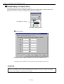
Sampling Trace
Opens the [Sampling Trace] window.
・You can see the ON/OFF information of the programmable controller's
relay or the registry information in the form of time chart.
Option Parameter
Opens the [Option Parameter] window.
・You can define the parameter settings of the model to save parameters in
the option module.
CAD I/F
Converts the ladder graphical information you are editing to an intermediate
language (ASCII code) corresponding to information exchange format.
・You can send the data through the communication port or can read/write
the data into external media.
3・26
Chapter 3 Basic Operation (Function Summary)
■ Window
Command
Function
Open New Window
Open the new window that carries the same content as the currently active Window .
Overlap Display
Display windows in piles.
Cascade Display
Display windows in a row.
Arrange Icons
Arrange icons under the window.
Window name1, 2, ...
Activate the assigned window.
■ Help
Command
Function
Find Topic
Display the table of contents, or“help”regarding the assigned item by the Keyword.
Version Data
(MMVIEW)
Displays the version of JW-100SP.
3・27
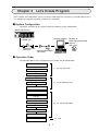
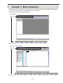
Chapter 4 Let's Create Program
Chapter 4
Let's Create Program
In this chapter, basic operations such as creating a ladder program, transferring a created program to the
PC, monitoring a program or printing a program, are explained.
■ System Configuration
Operations explained in this chapter require the following system configuration.
JW30H (JW-33CUH1)
Connection to
PG/COMM1 port
Personal computer
Windows 95
Ladder logic programming
software
(JW-100SP)
Connection cable
(JW-22KC)
Communication adapter
(JW-100SA)
■ Operation Order
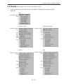
The operation orders that are explained in this chapter are described below.
Start-up JW-100SP
Create new files
4-1 Start-up JW-100SP
Setup model
Create ladder program
Check program
4-2 Create ladder program
Save files
Setup communication
Stop PC
Transfer program to PC
4-3 PC transfer/monitoring
Run PC
Start monitoring
Stop monitoring
Print ladder program
4-4 Print
4・1
Chapter 4 Let's Create Program
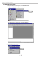
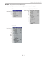
4-1 Start-up JW-100SP
1. Click [Start] button at the task bar on the screen of Windows 95/98.
2. Click [Programs]-[Sms]-[JW100SP] on the start menu.
Click here
JW-100SP will start-up, and the initial screen will be displayed.
3. Click [File]-[New] of the menu bar.
Click here
4・2
Chapter 4 Let's Create Program
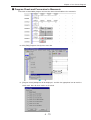
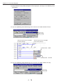
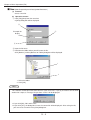
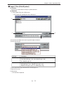
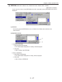
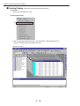
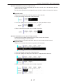
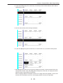
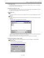
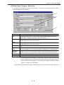
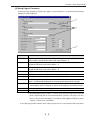
4. When the [New] dialog box is displayed, input the file name you are creating in the file name box.
(In the example below, "new" is input as the file name.)
If you want to change the position (directory) of the created program, click [Browse] button
and select the directory (Refer to the page 5-4 for more detail).
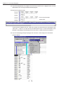
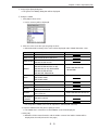
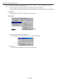
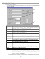
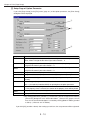
5. If you click [OK] button, [Select PC Model] Dialog box will be displayed.
6. After clicking [Series Selection] box, click [JW30H].
7. Click [JW-33CUH1] inside the [Model Selection] box.
8. If you click [OK] button, the input screen of ladder program will be displayed.
4・3
Chapter 4 Let's Create Program
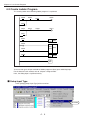
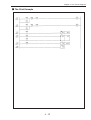
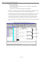
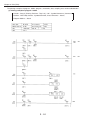
4-2 Create Ladder Program
The creating order of the following ladder programs is explained.
00000
00002
T0001
00020
00012
C0002
00021
00001
00010
00011
00003
TMR
0050
0001
00004
CNT
0010
0002
00005
00006
F-63
09100
INC
F-40
END
There are two types of input methods of ladder programs:direct input and dialog input.
For the detail of each method, refer to
“Chapter 6 Program Edit.”
Here, the dialog input is explained mainly.
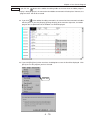
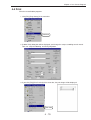
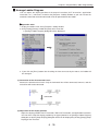
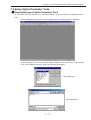
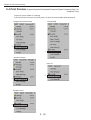
■ Setup Input Type
1.Click [Setup]-[Setup Input Type] of the menu bar.
Click here
4・4
Chapter 4 Let's Create Program
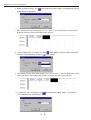
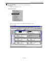
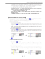
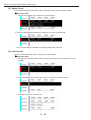
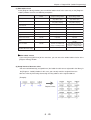
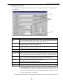
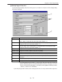
2. When [Setup Input Type] dialog box is displayed, setup the following, and click [OK] button.
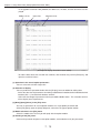
■ Inputting A Contact, B Contact and Coil
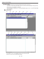
3. Move the mouse cursor to the cell that is at the left side up of the ladder display (column:0
row: 0), and click.
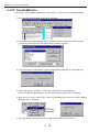
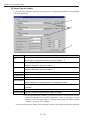
4. When inputting A contact, click [X] of the toolbar for editing ladder.
The following [A contact] dialog box will be displayed.
5. After inputting the relay number (No need of inputting when
“00000”
), click [OK] button. A
contact will be displayed, and the cell cursor will move to the right cell.
4・5
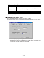
Chapter 4 Let's Create Program
6. When inputting B contact, click
of the toolbar for ediing ladder. The following [B contact]
dialog box will be displayed.
7. After inputting the relay number([2] in case of“00002”), click [OK] button. B contact will be
displayed and the cell cursor will move to the right cell.
8. To input TMR contact (A contact), first click
of the toolbar for ediing ladder. [A contact]
dialog box will be displayed, and press
inside the box.
9. After clicking [T0000], input TMR number ([1] in case of“0001”
), and click [OK] button. TMR
contact (A contact) will be displayed, and the cell cursor will move to the right cell.
10. To input coil (OUT instruction), click
[OUT] dialog box will be displayed.
4・6
of the toolbar for ediing ladder. The following
Chapter 4 Let's Create Program
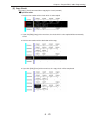
11. After inputting the relay number ([2] [0] in case of
“00020”
), click [OK] button. OUT instruction
will be displayed, and the cell cursor will move to the right cell.
12. Move the cell cursor to the row number 000001 , and after inputting A contact (00001) as the
same way as the order No.4 and No.5, move the cell cursor on the A contact (00001).
13. Click
. A contact (00001) will be connected by OR (OR connection).
14. Circuits between lines 2 and 3 are similar to the circuits of the lines between 0 and 1, so
create first the copy of the circuits between lines 0 and 1.
First, move the mouse cursor to the line number 000000, and drag the cursor to the line
000001.
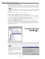
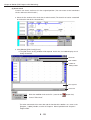
15. Click [Edit]-[Copy] of the menu bar.
Click here
4・7
Chapter 4 Let's Create Program
16. Move the mouse cursor to the row number 000002.
17. If you click [Edit]-[Paste] of the menu bar,
“copy”
is executed.
Click here
18. If you double click on the contact where a relay number is changed, input of the relay number
will be possible.
19. After inputting the relay number ([1] [0] in case of 00010), if you press [Enter] key, the relay
number will be changed, and the cell cursor will move to the next contact.
20. Input the relay number continuously, and complete the circuit. In addition, input [C] [2] in
case of CNT contact
“C0002.”
4・8
Chapter 4 Let's Create Program
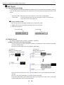
■ Inputting Timer and Counter
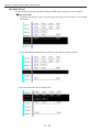
21. Input
“A contact 00003”
as the same way as the order No.3 to No.5.
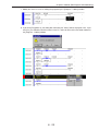
22. To input TMR instruction, click
of the toolbar for editing ladder. The following [TMR
Instruction] dialog box will be displayed.
23. Setup TMR type, TMR No. and setup value as the following.
24. If you click [OK] button, TMR instruction will be input.
25. After inputting
“A contact 00004”
and“A contact 00005”as the same way as the order No.3 to
No.5 ,move the cell cursor to right next to the count input
“A contact 00004”
.
26. When inputting CNT instruction, click
of the toolbar for ediing ladder.
The following [CNT Instruction] dialog box will be displayed.
4・9
Chapter 4 Let's Create Program
27. Setup CNT type, CNT No. and setup value as the following.
28. If you click [OK] button, CNT instruction will be input.
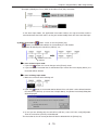
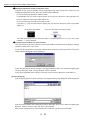
■ Inputting Application Instruction
29. Input“A contact 00006”as the same way as the order No.3 to No.5.
30. When inputting application instruction, click
of the toolbar for ediing ladder.
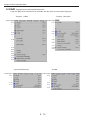
The following [Select Application Instruction] dialog box will be displayed.
31.There are two types of input methods for application instruction:a method to select the
instruction or a method to input the instruction number. Here, we input the instruction number.
First, input [F] [6] [3] at the instruction input.
4・10
Chapter 4 Let's Create Program
32. If you click [OK] button, [Timer/counter instruction] dialog box will be displayed.
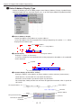
33. After clicking [
09100.
] , select [09000] and input [1] [0] [0]. Then you can assign the register
34. If you click [OK] button, F-63 (INC) instruction will be input.
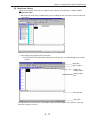
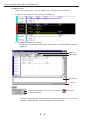
35. After moving the cell cursor to the next line, (the next position is optional), if you click
button, [Select Application Instruction] dialog box will be displayed. Here we input F-40 (END)
instruction by the method of selecting the instruction. First, double click [Execution condition
instruction] at the general classification chart.
Double click here
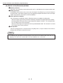
Reference
F-40 (END) instruction is automatically written to the final address “76777”
(
, in case of JW33CUH1) of the program memory. Therefore, the calculation is executed even without writing it in,
but if you write in F-40 (END) instruction right after a program has been created, the calculation
time will be short.
4・11
Chapter 4 Let's Create Program
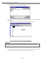
36. Double click [END] at the detail classification chart.
Double click here
37.If you double click [End instruction [F-40]], the instruction at the instruction input will be
displayed.
Double click here
38.If you click [OK] button, [Execution condition instruction] dialog box will be displayed.
39.If you click [OK] button, F-40 [END] instruction will be input.
4・12
Chapter 4 Let's Create Program
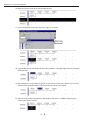
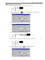
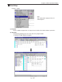
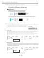
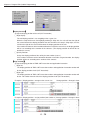
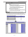
■ Program Check and Conversion to Mnemonic
Check the created ladder program and execute conversion of ladder to the mnemonic.
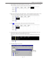
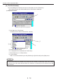
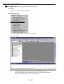
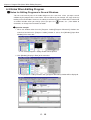
40. Click [Edit]-[Program Check] of the menu bar.
Click here
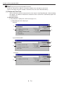
41. [Program Check] dialog box will be displayed, and click the appropriate item to mark the
check mark. Here all check marks are checked.
4・13
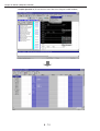
Chapter 4 Let's Create Program
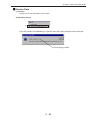
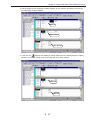
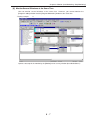
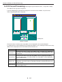
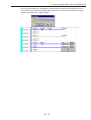
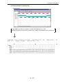
42. If you click [Start] button, the program check will start, and if there is a program error, an error
information at the message window will be displayed.
(Example of the program error)
←Over-using the output
00020 twice
If you execute the program check, it will also execute the conversion to the mnemonic at the
same time. If there is an error like the disconnected circuit, an error information at the
[Compile error] dialog will be displayed.If an error occurs, modify correctly the program.
43. If you click [Display]-[Change Display] of the menu bar, it will change to the mnemonic
program display.
Click here
4・14
Chapter 4 Let's Create Program
Reference If you click the
button of the toolbar for editing ladder at the time when the ladder program
display is being displayed, the conversion from ladder to mnemonic will take place. However, the
“program check”
will not be executed.
44. If you click
of the toolbar for editing mnemonic, the conversion from mnemonic to ladder
will take place. If you click [Display]-[Change Display] of the menu bar right after, the ladder
program that is optimized to fit the window size will be displayed.
45. If you click [File]-[Save] of the menu bar, the dialog box to save the file will be displayed. Click
[Save] to save the program you have created.
Click here
4・15
Chapter 4 Let's Create Program
4-3 PC Transfer//Monitor
Transfer the created ladder program to PC (JW-33CUH1), and execute the monitoring of data.
1. Click [Setup]-[Communication Setup] of the menu bar.
2. [Communication Setup] dialog box will be displayed, and select [PC itself]. Match the port
number of [COM.Port] to the port number of the personal computer.
3. If you click [Setup in Detail] button, [Setup COM Baud Rate] dialog box will be displayed.
4. Select
“high speed (115.2kbps)”. After clicking [OK] button, click [OK] button at
[Communication Setup] dialog box, and the setup communication will be completed.
5. When the PC is running, stop the PC. Click [PC]-[Start/Stop] of the menu bar, and the following
dialog box will be displayed.
Click here
6. Click [OK] button. Verify that it has been stopped at the RUN lamp of the PC.
4・16
Chapter 4 Let's Create Program
7. Click [PC]-[PC Transfer]-[Write] of the menu bar.
Click here
8. [PC Transfer Write] dialog box will be displayed, and check
“Program Memory”
. If you click
[OK] button, it will start the transfer (Here, only the program is being transferred.)
9. When the transfer is completed, the following dialog box will be displayed, and click [OK]
button.
10. Click [PC]-[Start/Stop] of the menu bar, the following dialog box will be displayed.
Click here
11. Click [OK] button. Verify that it has been running at the RUN lamp of the PC.
12. Click [Display]-[Changes Type of Monitor] of the menu bar.
Click here
4・17
Chapter 4 Let's Create Program
13. [Setup Monitor Display Mode] dialog box will be displayed, and setup as the following. Click
[OK] button.
14. If you click [Monitor]-[Start Monitoring] of the menu bar, the ladder monitor will start.
Click here
Thick line represents the condition
of running through.
Thin line represents the condition
of not running through.
Current value:BCD
Current value:decimal
15. If you click [Monitor]-[Stop Monitoring] of the menu bar, the ladder monitor will stop.
Click here
4・18
Chapter 4 Let's Create Program
4-4 Print
Print the created ladder programs. 1. Click [File]-[Page Setup] of the menu bar.
Click here
2. [Ladder Print] dialog box will be displayed, and change the setups according to each needs.
Here, we setup the following, and click [OK] button.
3. If you click [File]-[Print Preview] of the menu bar, the print image will be displayed.
Click here
4・19
Chapter 4 Let's Create Program
Clicking [Zoom In] button makes the display larger, and clicking [Zoom Out] button will make the
display smaller.
4. If you click [Print] button, [Print] dialog box will be displayed.
5. Click [Properties] button, and after changing the setup according to the need, click [OK] button.
6. If you click [OK] button at the [Print] dialog box, it starts printing.
4・20
Chapter 4 Let's Create Program
■ The Print Example
4・21
Chapter 5 Menu Operation (File)
Chapter 5 Menu Operation
The operation of each menu of the menu bar of the main window and the basic window (program:ladder/
program:mnemonic/system/data/symbol/parameter) are explained.
The menu bar varies according to the window.
・Main Window
Menu Bar
(Details in pages)
5-3
5-30
5-31
5-46
5-59
5-73
5-82
・[Program : Ladder] window
Menu Bar
(Details in pages)
5-3
5-12
5-29
5-30
5-31
5・1
5-46
5-59
5-73
5-76
5-82
Chapter 5 Menu Operation (File)
・ Menu bar of [Program : Mnemonic] window
(Details in pages) 5-3
5-12
5-29
5-30
5-31
5-46
5-59
5-73
5-76
5-82
・ Menu bar of [System/Data/Parameter] window
(Details in pages) 5-3
5-12
5-30
5-31
5-46
5-59
5-73
5-76
・ Menu bar of [Symbol] window
(Details in pages)
5-3
5-12
5-31
5-46
5-59
5・2
5-73
5-76
5-82
5-82
Chapter 5 Menu Operation (File)
5-1 File (Main/Program/System/Data/Symbol/Parameter)
If you click [File] at the menu bar of each window, [File] menu summary will be displayed.
・Program/System/Parameter
・Main
(Details in pages)
(Details in pages)
5-4
5-6
5-7
5-8
〃
5-4
5-6
5-9
〃
5-9
〃
〃
〃
〃
〃
・Data/Symbol
(Details in pages)
5-4
5-6
5-7
5-8
〃
5-11
5-10
5-9
〃
〃
〃
〃
〃
5・3
Chapter 5 Menu Operation (File)
■ New (Main/Program/System/Data/Symbol/Parameter)
(1) Function
Create a new file.
(2) Operation content
① Click [File]-[New] from the menu bar
⇒ [New] dialog box will be displayed.
②
③
Example for
display
④
② Input the file name.
③ Determine the folder where you will create the file.
Click [Browse]. and the [Browse for Folder] dialog box will be displayed.
1
2
1. Select the folder.
2. Click [OK].
Notes
・ This software cannot open more than one files at the same time. If you try to create a new file while
another file is open, a message "Do you close a File?" will be displayed.
⇒ If you click [No], JW-100SP starts.
⇒ If you click [Yes], the dialog box to save the current file will be displayed. After saving the file,
you can create a new file in the [New] dialog box.
5・4
Chapter 5 Menu Operation (File)
④ Click [OK] of [New] dialog box
⇒ The [Select PC Model] dialog box will be displayed.
⑤ Setup the model
1. Click [▼] of select series
⇒ series summary will be displayed.
2. Click the series name that you are going to select.
⇒ Selected model summary of the series will be displayed under "Model Selection" chart.
Series Selection Model Selection
JW20/20H
Remark
JW-21CU(H),JW-22CU(H)
JW50/70/100 JW-100CU,W-50CU,JW-70CU
JW50/70/100H
JW-100CUH,JW-100CUH (Expansion relay)
JW-50CUH,JW-70CUH
JW30H
JW-31CUH,JW-31CUH1
JW-32CUH,JW-32CUH1(15.5K)
JW-32CUH1(31.5K),JW-32CUM1
JW-33CUH,JW-33CUH1
JW-33CUH2,JW-33CUH3
JW10
JW-1324K/1342K
JW-1424K/1442K
JW-1624K/1642K
W100
ZW-1K0CU/1CU/2CU/3CU
W70/100H
ZW-1HCU,ZW-70CU
W16/51
ZW-160CU
ZW-501CU/CU2/CU3
J-board
Z-311J/312J/313J
Z-511J,Z-512J
VME Built-in
Controller
JW-32CV1/32CV2
All
All models (displayed above)
・Select JW-32CUH1 for
JW-32CUM1.
・Select JW-32CUH1 for Z-512J.
・The setup of the model at the time of shipment is JW100H(JW-100CUH).
3. Click the model name that you are going to select.
⇒ The model that is selected at "Current Model" chart will be displayed.
4. Click [OK]
⇒ Windows will be created in order, and the whole screen of the ladder window will be
displayed at the end.(refer to the next page)
5・5
Chapter 5 Menu Operation (File)
・ Display example of ladder window
■ Open (Main/Program/System/Data/Symbol/Parameter)
(1) Function
Open the existing file (program, system memory, data memory, symbol/comment, parameter).
(2) Operation content
① Click [File]-[Open] from the menu bar
⇒ [Open] dialog box will be displayed.
②
④
⑤
(Example for display)
5・6
③
Chapter 5 Menu Operation (File)
② Select the directory at "Look in"
③ Select the kind at "Files of type" box
File Type
JW100SPfile (*.pgm, *.syc, *.dfi, *.sys, *.prm), Program(*.pgm), System(*.sys),
Data(JW100SP type)(*.dfi), Symbol/Comment(JW100SP type)(*.syc), Parameter(*.prm)
・For classification and extension of the file, refer to the page 3-3.
④ Select the reading file
⇒ file that was selected at "File name" chart will be displayed.
⑤ Click [Open]
⇒ open the window of the selected file
Notes
・In JW-100SP, you can open only one file per file type: Program, System, Data, Symbol, and Parameter.
Also, by selecting the tab of the tree bar, you can change the windows.
■ Close (Program/System/Data/Symbol/Parameter)
Close the window of the opened file (Program/System/Data/Symbol/Parameter).
A conformation dialog box to save the file will be displayed before closing the window if the file has been
modified.
・If you close the window without saving, all modified content after it was last saved will be lost.
5・7
Chapter 5 Menu Operation (File)
■ Save (Program/System/Data/Symbol/Parameter)
Save the currently active file without changing its name or its saved place.
If the file has been modified after it was saved last time, the confirmation dialog box will be displayed.
・If you are saving by changing the name and the place of the saved file, use [Save As] of the [File] menu.
■ Save As (Program/System/Data/Symbol/Parameter)
(1) Function
Save the currently operating file by putting a new name.
(2) Operation content
① Click [File]-[Save As] from the menu bar.
⇒The [Save As] dialog box will be displayed.
②
⑤
③
④
② Determine the folder where you will save the file.
⇒Click [Browse]. and the [Browse for Folder] dialog box will be displayed.
1
2
1. Select the directory.
2. Click [OK].
③ Input the file name.
④ Select the file type.
⑤ Click [OK].
⇒The file will be saved.
5・8
Chapter 5 Menu Operation (File)
■ FD Verify (Program/System/Data/Symbol/Parameter)
Verify the files in operation with the files saved in the hard disk or floppy disk.
■ Page Setup (Program/System/Data/Symbol/Parameter)
Setup the format of the page for printing..
⇒ For details, refer to "Chapter 9 Print."
■ Print Program (Program/System/Data/Symbol/Parameter)
Print the content of the open window.
⇒ For details, refer to "Chapter 9 Print."
■ Print Preview (Program/System/Data/Symbol/Parameter)
Display the content of the open window as if printing.
⇒ For details, refer to "Chapter 9 Print."
■ Printer Setup (Main/Program/System/Data/Symbol/Parameter)
Setup the selection and the connection of the printer.
⇒ For details, refer to "Chapter 9 Print."
■ Quit (Main/Program/System/Data/Symbol/Parameter)
Quit JW-100SP.
A confirmation message will appear as to save the modified file before quitting the operation.
・If you close the window without saving, all contents that were modified since the last saving will be lost.
5・9
Chapter 5 Menu Operation (File)
■ Export Files (Data/Symbol)
(1) Function
Save the file about data memory or symbol/comment, specifying the file format.
(2) Operation
① Click [File]-[Export Files] from the menu bar.
⇒ The [Export Files] dialog box will be displayed.
②
④
⑤
③
② Determine the folder where you will save the file.
③ Select the file type.
File Type
Data memory
File Format
Data JW100SP type(*.dfi), Data JW50SP type(*.dat),
File JW50SP type(*.fil)
Symbol/Comment JW100SP type(*.syc), JW50SP V5.0 type(*.sye),
JW50SP V4.0 type(*.sym), Text type(*.txt), ZM70 type(*.mg)
- For the detail of file type and extension, refer to page 3-3.
④ Input the file name.
⑤ Click [Save].
⇒ The file will be saved.
5・10
Chapter 5 Menu Operation (File)
■ Import Files (Data/Symbol)
(1) Function
Import the file about data memory or symbol/comment.
(2) Operation
① Click [Import Files] of the [File] menu.
⇒ The [Import Files] dialog box will be displayed.
②
④
⑤
③
② Determine the folder where the file you will import is located.
③ Select the file type.
File Type
Data memory
File Format
(*.dfi, *.dat, *.fil)
Data JW100SP type(*.dfi), Data JW50SP type(*.dat),
File JW50SP type(*.fil)
Symbol/Comment (*.syc, *.sye, *.sym, *.txt, *.mg)
JW100SP type(*.syc), JW50SP V5.0 type(*.sye),
JW50SP V4.0 type(*.sym), text, ZM70 type(*.mg)
- For the detail of file type and extension, refer to page 3-3.
④ Input the file name.
⑤ Click [Save].
⇒ The file will be imported.
5・11
Chapter 5 Menu Operation (Edit)
5-2 Edit (Program/System/Data/Symbol/Parameter)
If you click [Edit] at the menu bar of each window, the edit menu summary will be displayed.
・Program:Ladder
・Program:Mnemonic
(Details in pages)
(Details in pages)
5-13
5-13
〃
〃
〃
〃
〃
〃
〃
5-14
5-17
〃
〃
5-14
5-17
〃
〃
5-18
〃
5-19
5-18
〃
〃
5-21
5-24
5-25
〃
5-19
5-20
5-21
5-24
5-25
5-26
5-27
・Symbol
・System/Data/Parameter
(Details in pages)
5-13
〃
〃
〃
(Details in pages)
5-13
〃
〃
〃
5-14
5-17
〃
5-27
5-14
5-17
〃
5・12
Chapter 5 Menu Operation (Edit)
■ Undo
(Program/System/Data/Symbol/Parameter)
Cancels the editing that has just been executed, and bring back the same cell /row as before.
・According to the operation content, there are items that you can not cancel.
■ Cut
(Program/System/Data/Symbol/Parameter)
Delete the selected cell/row and saves it momentary.
・Assign the cutting area before executing this operation.
・If you cut the cell/row, the content that was momentary saved will be replaced by the new content.
・In the program (ladder) window, the OR line (vertical) within the area will be out, but the OR line on the
area will remain.
Also, you can not cut the part of the instruction such as the application instruction that uses several
cells.
・In windows of system /data /parameter, only the data in the selected area will be 0 cleared. however, in
case of the system window, there is a part of the area you can not cut.
・In the symbol window, you can delete only the symbol/comment in the selected area.
・Refer to pages 6-24 to 6-25 (moving circuit) for the use example of the program (ladder) window.
■ Copy (Program/System/Data/Symbol/Parameter)
Copy the selected cell /row, and saves it momentary.
・Assign the copying area before executing this operation.
・If you copy the cell /row, the content that was momentary saved will be replaced by the new content.
・In the program (ladder) window, the OR line (vertical) within the area will be copied, but the OR line on
the area will not be copied.
Also, you can not copy the part of the instruction such as the application instruction that uses several
cells.
・In windows of system/data/parameter, only the data in the selected area will be saved momentary.
・In the symbol window, you can save only the symbol/comment momentary in the selected area.
・Refer to pages 6-23 (copying circuit) for the use example of the program (ladder) window.
■ Paste
(Program/System/Data/Symbol/Parameter)
Paste the momentary saved content from "cut"/"copy" operations to the assigned position.
・Complete "cut"/"copy" operations before executing this operation.
・When pasting, select "cell" if the saved content is cell, and select "row" if the saved content is row.
・In system /data /parameter window, data of the selected address will be replaced
withthe momentary saved data by "cut"/"copy" operations.
However, in case of the system window, there is a part of the area you can not paste.
・In the symbol window, the symbol/comment of the selected address will be replaced with the mo
mentary saved symbol/comment by "cut"/"copy" operations.
・Refer to pages 6-23 (copying circuit) for the use example of the program (ladder) window.
■ Image Copy (Program Ladder)
Save the ladder program as an image file of the bitmap format in the clipboard.
・You can paste it in the Excel or Word document.
5・13
Chapter 5 Menu Operation (Edit)
■ Find (Program/System/Data/Symbol/Parameter)
Assign the character line (address, instruction, symbol) in the selected file, and search.
There are two types of search methods: "Find for the first time" and "Find continuously."
[1] Find for the First Time
When searching a character string for the first time, input it in the [Find] dialog box. When the dialog
box appears, the address or data of the selected area of the current file is automatically input in the
[Find What] area.
(1) Operation content
① Click [Find] of the [Edit] menu. (Refer to the page 5-12)
⇒ [Find] dialog box will be displayed.
・Program
③
⑤
②
④
・System/Data/Symbol
③
⑤
②
④
・Parameter
③
⑤
②
④
5・14
Chapter 5 Menu Operation (Edit)
② Select of "Item to find"
According to the operation window, the object of search varies. (You cannot search the item other
than search objects.)
Data /Symbol
Program
System
Address,
Constant
Relay,Register
System memory Relay,Register
Instructions
STR, AND, etc.
Symbol/
Comment
Symbol, Comment,
Line comment
Distinguish the
uppercase and
lowercase
Symbol, Comment,
Line comment
File 8, 9
Search without
distinguishing file 8 and 9
Item to find
Parameter
Parameter
―
―
Symbol, Comment
―
―
Symbol, Comment
―
―
―
―
―
Comment
③ Input the strings
Item to find
The input content of the character line
Address
Constant
(Relay,
Register,
Setting value)
・When inputting the character line, there aren’t any distinctions between the
upper or lower case characters.
・When the high figure of the number is 0, like the relay address, you can omit
the zero..
(Example) 1. The valid character line when finding relay 00122
122, 00122
2. The valid character line when finding register ]0123
]123 (] of bracket)
3. The valid character line when finding register 89001
89001
Instructions
・When inputting the character line, there aren’t any distinctions between the
upper or lower case characters.
・When the high figure of the number is 0, like the relay address, you can omit
the zero..
(Example) 1. The valid character line when finding STR 00123
STR00123, str00123, Str123
2. The valid character line when finding application instruction
Fc012, Fc012, fc12
・In the window other than the program one, uppercase and lowercase
characters are always distinguished.
・In the program window, you can define whether to distinguish uppercase and
(Symbol,
lowercase characters.
Comment,
(Example) The valid character line (window other than program) when finding
Line comment)
symbol LS01
Program window: LS1, ls1, ls01
Other windows: LS1, LS01
Strings
④ Select search direction
From the beginning: Search from the beginning of the file.
To Top: Search from the cursor to the beginning of the file.
To Bottom: Search from the cursor to the end of the file.
⑤ Press the [Enter] key, or click [Find Next]
⇒ It starts finding, and the cursor moves to the found cell or row.
5・15
Chapter 5 Menu Operation (Edit)
[2] Find Continuously
In case of finding the character line that was once found, use the "Find history."
・Once found character line will be added to the "Find history" combo box.
(1) Operation content
①
(Display example of the program)
① Click [ ▼ ] of the "Find history."
⇒ Display the once found character line summary.
③
②
④
② Click the character to find
⇒ It is displayed on the combo box of "Find history."
③ Click (Find next) or ④ (Find previous)
⇒ It starts finding.
・ "Find" is also executed when you click [Find Next] or [Find Previous] of the [Edit] menu.
Notes
・There are no limit in the number of the character lines stored in "Find history." Also, once stored
character lines will not be deleted. When this software is terminated, all the character lines will
be cleared.
5・16
Chapter 5 Menu Operation (Edit)
■ Find Previous (Program/System/Data/Symbol/Parameter)
Find already assigned character lines towards forward in the selected file.
・Select the character line from "Find history" summary of the sub toolbar.
・Refer to the previous page for the operation method.
■ Find Next (Program/System/Data/Symbol/Parameter)
Find already assigned character lines backwards in the selected file.
・Select the character line from "Find historys" ummary of the sub toolbar.
・Refer to the previous page for the operation method.
■ Find Coil (Program)
Find the output (coil) that uses the relay address of the cursor position in the selected file.
・It starts finding from the cursor position towards the gaining direction of the program address, and
if nothing is found, it starts finding from the program address 0 to the cursor position.
(Find example)
Find coil
The cursor moves to the found coil.
5・17
Chapter 5 Menu Operation (Edit)
■ Insert Cell (Program:Ladder)
Insert the cell in the assigned position.
・You can select several cells.
・All cells that are right of the inserted position will move to the right direction the same amount of
columns of the cell inserted.
・Refer to the page 6-21 for the use example.
■ Insert Row
(Program)
Insert the row in the assigned position.
・All rows that are below the inserted position will move down the same amount of the inserted rows.
・If there is an instruction like the counter instruction /application instruction that occupy several rows,
you can not insert the row.
・Refer to the page 6-21 for the use example.
■ Delete Cell
(Program:Ladder)
Delete the cell of the assigned position.
・You can select several cells.
・All cells that are right of the deleted position will move to the left direction the same amount of columns
of the cell deleted.
・ Refer to the page 6-20 for the use example.
■ Delete Row
(Program)
Delete the assigned row.
・All rows that are below the deleted position will move upward the same amount of the deleted rows.
・If there is an instruction like the counter instruction /application instruction that occupy several rows,
you can not delete the row.
・ Refer to the page 6-22 for the use example.
5・18
Chapter 5 Menu Operation (Edit)
■ Create Line Comment (Program)
Make the assigned line to the line comment.
・An input box is displayed in the row, so that you can write in the comment.
・The character number of the line comment is 100 characters.
・A Row that become the line comment becomes NOP instruction inside the PC.
・Rows during the network can not become line comments.
・ In the ladder, you can insert the line comment in the row where the ladder circuit exists, but in the
mnemonic, you can only create the line comment in the program address of the NOP instruction.
(Example)
Ladder program
After selecting the row number
with the cursor, click [Edit][Create Line Comment]. Then,
the line comment will be
inserted. After inputting the
comment character, establish
the command with the [Enter]
key.
Mnemonic program
← Inside the PC, it becomes the NOP instruction.
← Inside the PC, it becomes the NOP instruction.
← Inside the PC, it becomes the NOP instruction.
5・19
Chapter 5 Menu Operation (Edit)
■ Zoom
(Program : Ladder)
Enlarge /contract the window display of the ladder program.
(1)
(2)
(1) Zoom (+)
Enlarge 1 rank up the window display of the ladder program.
・Enlargement rates are: 113%, 125%, 138%, 150%, 163%, 175%, 188%, and 200%.
・You can enlarge, for example, from 88% → 100%.
・You can select from the magnifying power chart of the sub toolbar.
(2) Zoom (–)
Contract 1 rank down the window display of the ladder program.
・Contraction rates are: 88%, 75%, 63%, 50%, 38%, and 25%.
・You can contract, for example, from 150% → 125%.
・You can select the contraction rate from the magnifying power chart of the sub toolbar.
5・20
Chapter 5 Menu Operation (Edit)
■ Jump (Program)
Move (jump) to the assigned row. There five types for ladder and four types for mnemonics.
(1)
(2)
(3)
(4)
(5) *
(Menu of ladder)
* "To Program Address" (5) is not for mnemonics.
(1) To Top Row
Move to the front of the window.
(2) To Unedited Row
In case of the ladder, it moves to the unwritten row, and in case of the mnemonic, it moves to the
NOP instruction.
(3) To Assigned Row
Moves to the assigned row number by the [Jump to Assigned Row] dialog box.
5・21
Chapter 5 Menu Operation (Edit)
(4) To Address Mark
If you select the address mark that was setup already by the [Go to Address Mark] dialog box , it
moves to the row where the address mark was added.
●About the address mark function
You can add address mark in the optional row of a window.
① Adding method
If you click in the area of row selection, the address mark will be displayed on the left of the row.
Address mark
Area of row selection
・If you double click in the row that contains the address mark, the address mark will be
deleted.
・You can also add the address mark to the row which was assigned as the line comment.
② Number of address marks
You can add maximum 256 address marks.
③ Using method
If you click [Jump]-[To Address Mark] by the [Edit] menu, [Go to Address Mark]
dialog box will be displayed.
・ If you click [Go to] after selecting the address mark, it moves to the row containing this
assigned mark.
・ The line comment is also displayed, so that it is useful to add the address mark to the line
comment.
5・22
Chapter 5 Menu Operation (Edit)
(5) To Address Mark
Move to the address specified in the [Jump to Program Address] dialog box.
■ Library (Program : Ladder)
In the library window, "Create library," "read file," and "save file" operations are executed. This
operation is executed under the [Library] of the [Edit] menu.
・Program:Ladder
● Library
Item
Content
Read
If you click [Library]-[Read], the library window will be displayed. In addition, in
the library window, if you click [File]-[Read], [Read from library] dialog box will
be displayed. The file is selected in this dialog box, and the file will be read.
・It can read the file that was setup in the same model as the library window.
Also, the file that can read is only the library file that carries the extension LB2.
Register
If you click [Library]-[Register] after selecting the register area at the program:
ladder window, the library window will be displayed under the condition of the
select area being copied. If you click [File]-[Save As] at this window,
[Register library file] dialog box will be displayed. Save it with the file name.
Refer to "Chapter 6 Program Edit" for more details on the library.
5・23
Chapter 5 Menu Operation (Edit)
■ Program Check (Program)
(1) Function
Check the grammar and the format of the program
The following are the check items.
Check item
Stack use condition
MCS /MCR use condition
JCS /JCR use condition
Double use of the output instruction
Double use of TMR /CNT /MD instruction
Use condition of ONLS /ONLR
Use condition of Label
Use condition of FOR /NEXT instruction
(2) Operation content
① Click [Edit]-[Program Check] of the menu bar.
⇒ [Program Check] dialog box will be displayed.
②
③
② Select the check item
Click the check box that contains the item to check.
⇒ The check mark will be displayed.
③ Click [Start] button
⇒ The program of the check item will be checked.
・The check result will be displayed at the message bar window.
5・24
Chapter 5 Menu Operation (Edit)
■ Converts Data in Batch (Program)
(1) Function
The whole program including relay /timer /register /label number are modified in batch.
(2) Operation content
① Click [Edit]-[Converts Data in Batch] of the menu bar of the program
⇒ [Converts Data in Batch] dialog box will be displayed.
③
④
②
⑤
② Select the item to convert
Select the kinds (Relay, TMR /CNT, Register, Label) for conversion data in batch.
③ Setup the address
Setup the start (front) address, end address, the front address of the destination address of the
relay /register, etc.
④ Select "Is Added /None" of the "Converts Symbol"
In case of changing the symbol/comment at the same time, select "Is Added", and in case of not
changing the symbol/comment, select "None."
If you setup "Is Added," the address of the symbol /comment that attaches to the address will
also be changed at the same time.
⑤ Click [Exec.] button.
⇒ Data in batch are changed.
(3) Conversion example
Before the Conversion
Converts data
in batch
After the Conversion
Items to convert :Relay
Start address :100
End address
:101
Destination
:200
Converts symbol :None
5・25
Chapter 5 Menu Operation (Edit)
■ Replacing Contacts
(Program : Ladder)
(1) Function
Interchange A contacts with B contacts in the specified relay address, and vice versa, about the
program in operation.
(2) Operation content
① Click [Replacement No and Nc] of the [Edit] menu in the menu bar of the program:ladder.
⇒ [A Contact
B Contact ] dialog box will be displayed.
②
③
② Determine the relay address whose contacts will be interchanged.
⇒ If you select a contact in the program window in operation, the related relay address will be
automatically displayed.
③ Click [Execute].
⇒ The [Result] dialog box is displayed, and you can see how many contacts have
been interchanged.
(Example) When you have replaced the contacts in the relay address 12000
5・26
Chapter 5 Menu Operation (Edit)
■ Assigns Symbol(Program : Ladder/Symbol)
(1) Function
When creating the ladder program, assign the symbol which was temporarily registered by the
symbol input, to the actual address.
(2) Operation content
① Click [Edit]-[Assign Symbol] of the menu bar
⇒ [Assign Symbol] dialog box will be displayed.
④
②
③
(Display example)
Item
Content
Symbol
Display the temporary registered symbol.
Type
Display the temporary registered data memory classification (relay /register,
etc.) of the symbol.
Address
If you assign the address to the symbol, the address will be displayed.
● In case of the direct input of the address
② "Double click the row of the assign operation" or "Input [Enter] key after selecting the row of the
assign operation"
⇒ Open the box for input on the address chart.
③ Input address
● In case of selecting / inputting the address
② Click to the right of the mouse after selecting the row of the assign operation
⇒ The select menu will be displayed.
・Type : at the time of register
・Type : at the time of relay
③ Input the address after selecting the item of the address
5・27
Chapter 5 Menu Operation (Edit)
④ Click [File]-[OK]
⇒
(Display example)
・ The symbol assigning the address will be registered in the symbol/comment window.
・ The progress of the register will be displayed at the message bar.
・ The symbol that completed the registration will be deleted from the list of [Assign Symbol]
dialog box.
・ Until you click [OK], the symbol assigning the address remain temporary registered.
(3) Assign example
Before assigning the symbol
Display Type=
“Address+Symbol”
(But the input symbol is: Display Type=at the“Symbol”)
Assign symbol
After assigning the symbol
Display Type=
“Address+Symbol”
5・28
Chapter 5 Menu Operation (Instruction)
5-3 Instruction (Program)
If you click [Instruction] at the menu bar of the [Program] window, [Instruction] menu summary will
be displayed.
・Program:Ladder
・Program:Mnemonic
Menu item
Content
A contact
When editing the ladder, Input A contract.
B contact
When editing the ladder, Input B contract.
Horizontal line
When editing the ladder, Input horizontal line.
Vertical line
When editing the ladder, Input vertical line.
STR
When editing the mnemonic, input STR, STR NOT, AND STR, OR STR
instruction.
NOT
When editing the mnemonic, input STR NOT, AND NOT, OR NOT
instruction.
AND
When editing the mnemonic, input AND, AND NOT, AND STR instruction.
OR
When editing the mnemonic, input OR, OR NOT, OR STR instruction.
Input OUT instruction (coil).
OUT
TMR
Input TMR instruction.
When editing the mnemonic, it's also used as the input of TMR contact.
CNT
Input CNT instruction.
When editing mnemonic, it's also used as the input of CNT contact.
FUN
Input the application instruction.
F43
Input F-43 instruction (reverse bit).
F44
Input F-44 instruction (differential ON).
F45
Input F-45 instruction (differential OFF).
Input F-20 instruction (MD).
F-20 (MD)
・If you click[F-20 (MD)],[Input F-20 (Maintenance display)]dialog
box will be displayed.
Refer to “Chapter 6 Program Edit” for the detail on the instruction input.
5・29
Chapter 5 Menu Operation (Monitor)
5-4 Monitor
(Main/Program/System/Data/Parameter)
If you click [Monitor] at the menu bar of each window, [Monitor] menu summary will be displayed.
・Main
・Program : Mnemonic/System/Data/Parameter
・Program : Ladder
Menu item
Content
Start Monitoring
Start the monitoring.
Stop Monitoring
Stop the monitoring.
I/O Force Processing
Select either ON/ OFF of the relay of the PC by force.
Edit Circuit
Modify, insert, or delete the program of the PC, or interchange
the contacts, during the monitoring.
Refer to "Chapter 8 Monitor" for the details on the monitor.
5・30
Chapter 5 Menu Operation (Display)
5-5 Display (Main /Program /System /Data /Symbol /Parameter)
If you click [Display] at the menu bar of each window, [Display] menu summary will be
displayed.
・Main
(Details in pages)
5-33
〃
〃
〃
〃
〃
・Program:Ladder
・Program:Mnemonic
(Details in pages)
(Details in pages)
5-34
〃
5-35
5-36
5-37
5-38
5-42
5-34
5-36
5-38
5-33
〃
〃
〃
〃
〃
5-33
〃
〃
〃
〃
〃
5-43
〃
〃
・Data
・System
(Details in pages)
5-43
〃
〃
〃
〃
(Details in pages)
5-43
〃
〃
〃
〃
5-44
〃
〃
5-44
〃
〃
5-45
〃
5-33
〃
〃
〃
〃
〃
5-45
〃
5-33
〃
〃
〃
〃
〃
5・31
Chapter 5 Menu Operation (Display)
・Parameter
・Symbol
(Details in pages)
5-43
〃
〃
〃
〃
(Details in pages)
5-44
〃
〃
5-45
〃
5-33
〃
〃
〃
〃
〃
5-33
〃
〃
〃
〃
〃
5・32
Chapter 5 Menu Operation (Display)
■ Main Toolbar /Sub Toolbar /Status Bar /Tree Bar / Toolbar for Editing
Ladder / Toolbar for Editing Mnemonic /Toolbar for Editing Data /
Message Bar (Main/Program/System/Data/Symbol/Parameter)
Select "yes /no" of the display of each bar at the window. When "yes" is selected, a check mark is displayed besides each bar name.
・In case of [Program : Ladder] window
①
②
⑤
④
⑥
③
・In case of [System] window
①
②
⑦
④
⑥
③
① : Main Toolbar
② : Sub Toolbar
③ : Status Bar
④ : Tree Bar
⑤ : Toolbar for Editing Ladder
In case of [Program : Mnemonic] window, the toolbar for editing
mnemonic will be displayed at this position.
⑥ : Message Bar
⑦ : Toolbar for Editing Data
5・33
Chapter 5 Menu Operation (Display)
■ Select Address Display Type (Program:Ladder)
Select display type of the address/symbol/comment at the ladder program.
・Program : Ladder
Item
Normal
Content
Only the address will be displayed.
"*****" will be displayed if it’s not input at the symbol, and the address is not
assigned. (Symbol assigning method⇒ refer to the page 5-27)
If the symbol is setup, the symbol will be displayed. Also, all address inputs are executed
Symbol
with the symbol. (Symbol input ⇒ refer to the pages 6-8, 6-15)
If the comment is set up, the comment will be displayed in 8 characters by 4 lines. You can
Comment (8c, 4l)
input the comment when inputting the address.
If the comment is set up, the comment will be displayed in 16 characters by 2 lines. You
Comment (16c, 2l)
can input the comment when inputting the address.
When it is set to Address, you can also see the symbol or comment. You can input the
Full (Address/
Symbol/Comment) symbol/comment when inputting the addres.
・Refer to the page 6-2 about the example for display.
■ View Change (Program)
Change between the ladder window and the mnemonic window.
・When changing, if one of the windows has been edited after the last transformation, a confirmation
message asking either "from ladder to mnemonic" or "from mnemonic to ladder" will be displayed.
Ladder window
View Change
Mnemonic window
5・34
Chapter 5 Menu Operation (Display)
■ Select Monitoring Display Type
(Program : Ladder)
(1) Function
Assign (select) the monitor type during the monitor at the ladder window.
Item
Content
Select the display type (simple display /detail display) of the application instruction.
◎Simple Display
Only the current value will be displayed at the register of the application instruction.
All current values of the register are displayed by the notation that was selected at
Type of Monitor
Display Mode
the "type of register display mode."
The current value of the byte /word treatment instruction will be displayed as byte
/word, but the current value of the double word treatment instruction will be
displayed in word. (only the lower words are displayed.)
◎Detail Display
Display the current value and the notation in the register of the application
instruction.
You can select the "effectire area of type of register display mode."
Type of Register
Display Mode
Effective Area of
Type of Register
Display
The current value at the byte /word /double word treatment instruction will be
displayed in byte /word /double word display.
Select the notation display type of the register during the application instruction from
HEX (hexadecimal notation), DCML(decimal notation), OCT(octal notation).
Select the effective area of the notation display which was selected at the "type of
register display mode." If the "tye of monitor display mode" is the "easy display," you
can not select. In this case, it will be "all registers."
◎All Registers
Display the current value by the notation selected at the "type of register display
mode" to all the registers during the application instruction.
◎Infinitive Register of Number Type
Only the register of the undecided value type during the application instruction will
display the current value by the notation selected at the "type of register display
mode."
The register during the instruction (F-08[transfer of octal notation]etc.) whose
value type has been established will display the current value by the notation of the
value type.
Example 1) Type of monitor display mode : simple display, type of register display mode : DCML
Decimal notation display
Decimal notation display
Decimal notation display
Example 2) Type of monitor display mode : detail display, type of register display mode : DCML,
effective area of type of register display mode : infinitive register of number type
Decinal notation display
(the register with undecided
numerical value type)
Decimal notation display
(the register with established
numerical value type)
Octal notation display
(the register with established
numerical value type)
5・35
Chapter 5 Menu Operation (Display)
(2) Operation content
① Click [Display]-[Changes Type of Monitor] of the menu bar of the program:ladder
⇒ [Setup Monitor Display Mode] dialog box will be displayed.
② Select type of monitor display mode. Select from
either "Simple Display" or "Detail Display."
②
③ Select type of register display mode
Select from "HEX" (hexadecimal notation),
③
"DCML" (decimal notation),"OCT" (octal notation).
④
④ Select effetive area of type of register display
When selecting "Detail Display," select either "All
Registers" or "The Infinitive Register of Number
Type."
⑤
⑤ Click [OK]
⇒ Selected content is registered.
■ Change Segment File
(Program)
Change the display of the program memory (file8/9).
・When the memory volume of the program exceeds 31.5K words, change the display between 00000
and 76777 (file8) and 100000 and after (file9) of the program address.
・File 9 is used as the destination of the divided branch created by the jump instruction (F-141,F-151), or
used as the hangar of the sub routine program created by the sub routine call instruction (F-142,F-148).
Address
File 8
000000
Address
100000
File 9
F-140
LB0000
LABL
JUMP
F-141
LB0000
JMP
076776
076777
Address
000000
176776
176777
END
File 8 Address
100000
END
File 9
F-140
LB0001
LABL
CALL
F-142
LB0001
CALL
076776
076777
END
F-143
RET
176776
176777
END
・Each function such as program check, change from ladder to mnemonic, change from mnemonic to
ladder, transfer to the main PC, save in the file, or print will be executed in batch at the file 8/9.
5・36
Chapter 5 Menu Operation (Display)
■ Word Wrap
・Program:Ladder
Note:
You cannot edit the program when it is
word-wrapped.
(1) Function
Display a ladder wrapped when it is longer than the width of the ladder window in operation.
(2) Operation
Click [Display]-[folding]-[On] in the menu bar of the program:ladder.
⇒ Display the ladder program wrapped.
5・37
Chapter 5 Menu Operation (Display)
■ Data List (Program)
(1) Function
Display/print the using-condition chart of the relay, timer・counter, register and label.
・The data list at the [Program : Ladder] window will be automatically changed to mnemonic
before the display. As a result, the circuit of the ladder program must be normal in order to
display the data list.
If you click [Display]-[Data List] by the menu bar of the [Program : Ladder]/ [Program : Mnemonic]
window, [Data List] dialog box will be displayed.
(Display example)
Item
Content
Used address will display※(××). ×× of (××) describes the number of
addresses.
Display of ※ Content
Address
Symbol
Comment
−
Use as Contact
*
Use as Coil
T
Use as Timer
C
Use as Counter
Displayed when the symbol/comment is registered at the address.
※××××× [−−−−] will be displayed.××××× describes the Program
address, and −−−− describes the network (circuit) number.
Cross reference
Display of※ Content
*
Use as output
/
Use as B contact
Note that the network number will not be displayed at the [Program :
Mnemonic] window.
5・38
Chapter 5 Menu Operation (Display)
(2) Operation content
Explain the menu operation of the [Data List] dialog box.
⇒ Refer to the
next page
● [File] menu
Item
Close
Page Setup
Print
Content
Close the data list file that is being displayed.
Setup the format of the page for printing the data list.
・If you click [Page Setup], [Setup Print of Data List] dialog box will be
displayed.
Print the data list.
Print Preview
Display the image data list as if printing.
Setup selection /connection of the printer.
Printer Setup
・If you click [Printer Setup], [Printer Setup] dialog box will be
displayed.
・For more details of printing data list, refer to "Chapter 9 Print."
5・39
Chapter 5 Menu Operation (Display)
● [View] menu
Item
Content
Assign the address to be displayed in the data list at the [Assign Address]
dialog box. [Assign Address] dialog box will be displayed when this
particular item is clicked.
Assign Address
・If you click [▼] and select the kinds of register, and click [OK] after
inputting the address, the data list of the assign area will be displayed.
You can also assign the address by "double click the left side of the
mouse" or by inputting the [Enter] key.
After selecting the program address of the cross reference display, if you
click [View]-[Jump], the cursor will move to the instruction of the program
address. Note that, you can also do the same operation by
"double click the left side of the mouse." the program address of the cross
reference display.
Displays Again Create again the data list for every program and display.
Assign the display type of the data list at the [Setup Display Type] dialog
box. [Setup Display Type] dialog box will be displayed when this particular
item is clicked.
Jump
Display Type
◎ Symbol Display
Select "Do / Undo" of the display of the symbol which is setup at
relay /register. Select the item by clicking.
◎ Comment Display
Select "Do / Undo" of the display of the comment which is setup at
relay /register. Select the item by clicking.
◎ Reference Display
1 Row
Detail
Undo
: After the assigned address, display the cross reference of the
continuous address by each row.
: Only the cross reference of the assigned address will be
displayed repeatedly inside the cross reference display area.
: Cross reference is not displayed.
5・40
Chapter 5 Menu Operation (Display)
(3) Use example
● Ladder Program
← Network number 0
← Network number 1
← Network number 2
← Network number 3
[Note] 1 comment line is 1 program address and 1 network.
● Data List
Display type−Symbol Display : "Undo", Comment Display : "Undo", Reference Display : 1 Row
Assign Address : 00000
Network number
Program address
2 contact
1 coil
A contact
B contact Assign Address:TC0000
2 timer contact
Timer instruction
1 counter instruction
1 counter contact
5・41
Output
Chapter 5 Menu Operation (Display)
■ Arrange Ladder Diagram (Program : Ladder)
(1) Function
You can optimize the following: the connection of the disconnected circuit of the created ladder
circuit, adjustment of the display position of the output instruction (OUT instruction, /application
instruction etc), re-arrangement of the MCS/JCS condition display,re-arrangement of the ladder
diagram’s layout.
Item
Content
Connection of
Re-connect the disconnected circuit. Only the horizontal line can be
Disconnected Circuit
connected, and you can not connect the vertical line.
Adjust the display position of the OUT instruction, TMR/CNT
Adjustment of Display
instruction, application instruction.
Position
You can setup the display position by selecting the [Open] button
inside the [Arrange Ladder Diagram] dialog box, or at the [Setup
Display Pattern] dialog box by clicking [Setup]-[Setup Display
Pattern] by the menu bar.
Arrangement of MCS JCS Check the valid area of the MCS(F-30), JCS(F-41)condition, and
Condition’s Display
display "M" (MCS), "J" (JCS) to the row number of the valid area.
Re-arrangement of Ladder Omit unnecessary horizontal lines of the ladder circuit, and gather
Diagram’s Layout
the ladder element to the left side.
・For more details of the display example etc., refer to the pages 6-35 to 37.
(2) Operation content
① Click [Display]-[Arrange Ladder Diagram]
by the menu bar of the program : ladder.
⇒ [Arrange Ladder Diagram] dialog box
will be displayed.
② Select item
Click the check box of the item to execute.
⇒ The check mark is displayed.
③ Setup screen
Click [Open] button when setting up the screen for adjustment of the display position.
⇒ [Setup Display Pattern] dialog box will be displayed.
The setup at the [Setup Display Pattern] dialog box is same as the setup at the [Setup]-[Setup
Display Pattern], so please refer to the page 5-57.
If you click [OK] at the [Setup Display Pattern] dialog box, or click [Cancel] button,
you will be back to the [Arrange Ladder Diagram] dialog box.
④ Click [Exec.]
⇒ Execute the item of the check mark.
5・42
Chapter 5 Menu Operation (Display)
■ Displays in Symbol/ Displays in Comment/ Displays in Symbol &
Comment (Program/Mnemonics)
Change the display of symbol/comment.
Item
Content
Add Symbol
Display symbol
Add Comment
Display comment
Add Symbol Comment
Display symbol and comment at the same time.
■ Displays in Binary Notation /Displays in Octal Notation /Displays in
Decimal Notation /Displays in Decimal Notation (with +-)/Displays in
Hex Notation /Displays in ASCII (System/Data/Parameter)
Select the display of data (Binary notation/Octal notation/Decimal notation/Decimal Notation (with +-)/
Hexadecimal notation/ASCII).
※
※ You cannot select
"Display in Decimal Notation (with +-) for System.
• The example on the left is in the case of "Data."
Item
Content
Displays in Binary Notation
Displays data in binary notation.
Displays in Octal Notation
Displays data in octal notation.
Displays in Decimal Notation
Displays data in decimal notation.
Displays in Decimal Notation
(with +-)
Displays in decimal notation
with a plus or minus sign.
Displays in Hex Notation
Displays data in hexadecimal notation.
Displays in ASCII
Displays data in ASCII type.
5・43
Chapter 5 Menu Operation (Display)
■ Displays in Byte /Displays in Word /Displays in Double Word
(System/Data/Parameter)
Select the display of data (Byte/Word/Double word).
Item
Content
Displays in Byte
Displays data in byte module.
Displays in Word
Displays data in word module.
Displays in Double Word Displays data in double word module.
5・44
Chapter 5 Menu Operation (Display)
■ Displays in Detail /Displays as a List (System/Data)
Select the display of data from the detail or list.
Menu item
Content
Detail Display
Displays in one row, and symbol /comment is also displayed by the window.
Displays in List
Displays maximum data that can be displayed in the window in several rows.
Window
System
Data
Menu Item
Display Content
Displays in Detail
Address, Data, Comment
Displays as a List
Address, Data
Displays in Detail
Address, Data, Symbol, Comment
Displays as a List
Address, Data
● Display example (example of data:
:relay)
・Displays in Detail
・Displays as a List
5・45
Chapter 5 Menu Operation (Setup)
5-6 Setup (Main/Program/System/Data/Symbol/Parameter)
If you click [Setup] by the menu bar at each window, [Setup] menu summy will be displayed.
・Main /Program : Mnemonic /System /Data /Parameter
(Details in pages)
5-46
5-47
5-48
5-54
・Program : Ladder
・Symbol
(Details in pages)
(Details in pages)
5-46
5-47
5-48
5-54
5-46
5-47
5-48
5-54
5-55
5-56
5-57
5-58
■ Select PC Model (Main/Program/System/Data/Symbol/Parameter)
(1) Function
Setup the PC model that will be the object of edit/monitor.
・You can only use one model at a time even you have opened several windows .
(2) Operation content
If you click [Model Setup] by the [Setup] menu, [Model Setup] dialog box will be displayed.
・Details on this operation is same as "New" (refer to the page 5-4).
5・46
Chapter 5 Menu Operation (Setup)
■ Select Memory Capacity (Main/Program/System/Data/Symbol/Parameter)
(1) Function
Setup the volume of the program memory.
・Setup the memory volume of the PC model which has been setup.
(2) Operation content
If you click [Memory Capacity Setup] by the [Setup] menu, [Select Memory Capacity] dialog box
will be displayed.
①
②
(In case of JW-100CUH)
① Click [▼]
⇒ Display the possible (for setup) memory volume summary of the model which has already been
setup.
(In case of JW-100CUH)
・Select the memory volume.
② Click [OK]
⇒ Setup the memory volume.
5・47
Chapter 5 Menu Operation (Setup)
■ Setup Communication (Main/Program/System/Data/Symbol/Parameter)
[1] Function
Setup the PC which will be the object of communication, or setup the communication port of the
personal computer.
Communication object Operation Method
PC itself
Network
Remote I/O
Modem
Ethernet
Operate the PC by connecting the unit between the personal computer and
the PC with the communication adapter(JW-100SA)and connection cable.
・When the model is JW30H, you can setup the communication baud rate.
Connect the personal computer to the network module/ ME-NET module , and
operate the PC which is connected to the satellite net /ME-NET/SUMI-NET.
Connect the personal computer to the remote I/O slave station module
(JW-20RS), and operate the master PC that is connected to the satellite net.
Connect the personal computer to the network module through modem, and
operate the PC.
Operate the PC connected to Ethernet.
[2] Operation Content
If you click [Communication Setup] by the [Setup] menu, [Communication Setup] dialog box will be
displayed.
④
①
③
②
・① to ④ will be compatible to the following ① to ④.
(1) In case of connecting with the PC itself
① Click [PLC itself].
② Set up the communication port and timeout duration of the personal computer.
③ When the model is JW30H, click [Setup in Detail].
⇒ [COM Baud Rate Setup] dialog box will be displayed.
・ Select either standard communication baud rate (19.2kbps) or high speed (115.2kbps).
The possible combinations of the communication during the high speed are the PC that
control module is JW-31CUH1/32CUH1/32CUM1/33CUH1/33CUH2/33CUH3, and it is limited to the personal computer that is compatible to 115.2kbps. If the personal computer is not
compatible to 115.2kbps, select the high speed (115.2kbps). You will be then able to communicate by 19.2kbps.
④ Click [OK]
⇒ The setup will be completed.
5・48
Chapter 5 Menu Operation (Setup)
(2) In case of network connection (① to ④ ⇒ corresponding to page 5-48)
① Click [Network]
② Set up the communication port and timeout duration of the personal computer.
③ Click [Setup in Detail]
⇒ [Setup in Detail] dialog box will be displayed.
Operation Item
Operation Content
Select from standard/expansion
Network
Configuration
Operate the PC of the other station that is connected to the
Standard SATELLITE-NET/ME-NET/SUMI-NET (remote operation of one
layer)
Relay the optional station that is connected to the SATELLITENET/ME-NET/SUMI-NET, and operate the PC of the other station
Expansion
that is connected to the SATELLITE-NET/ME-NET/SUMI-NET via
the relay station. (remote operation of two layers)
Setup the station number of the target station that will be the object of
communicate and the kind of module.
Target Station
Station No.
0 to 77(8)
Kind of Module
SATELLITE-NET/ME-NET/SUMI-NET
When the network organization is the "expansion," setup the station
number/kind of module/rack number/slot number of the relay station.
Relay Station
Station No.
0 to 77(8)
Kind of Module
SATELLITE-NET/ME-NET/SUMI-NET
Rack No.
0 to 7
Slot No.
0 to 15
・If you click [▼], the kind of module of the target station /relay station will be displayed in
summary.
④ Click [OK]
⇒ The setup will be completed.
5・49
Chapter 5 Menu Operation (Setup)
(3) In case of remote I/O connection (①∼④ ⇒ corresponding to page 5-48)
① Click [Remote I/O]
② Set up the communication port and timeout duration of the personal computer.
(The "setup detail" of ③ is not necessary)
④ Click [OK]
⇒ The setup will be completed.
5・50
Chapter 5 Menu Operation (Setup)
(4) In case of modem connection (①∼④ ⇒ corresponding to page 5-48)
① Click [Modem]
② Set up the communication port and timeout duration of the personal computer.
③ Click [Setup in Detail]
⇒ [Communication Setup] dialog box will be displayed.
Operation Item
Operation content
Contact
Input the name of company/person you will communicate, if necessary.
TEL Number
Input the telephone number of company/person/computer you will
communicate. If you are using PBX (e.g. dial 0 to outside line),
check the [Outside line] box.
Address book
You can register telephone numbers or other information in the address book.
You can register 100 contact numbers from #0 to #99. Information you have
registered is imported to the [Communication Setup] dialog box when you
select the telephone number and click [OK].
When you click the [Address book] button, the [Address book] dialog box
will be displayed.
Input the number, name, and telephone number, and click [Add].
The information will beregistered in the address book.
To delete the information, select the number and click [Delete].
5・51
Chapter 5 Menu Operation (Setup)
Operation Item
Operation content
Time Out Times
Set up the duration of communication timeout between the modem and
JW-100SP. The timeout duration varies, depending on conditions of the
personal computer and the telephone line. Set it up according to the situation.
Telephone circuit
Setup Network
Select the type of your telephone line (pulse or tone).
Refer to "Network Connection."
If you connect a new modem, set up the modem itself first.
When you click the [Setup Modem] button, the [Modem setting] dialog box
will be displayed.
Modem setting
You need to set up the modem of both the PC and the personal computer.
Connect the modem to the personal computer with a straight cable of
RS-232C (usually attached to modem).
To set up the modem of the PC, select [PLC side]; to set up the modem of
the personal computer, select [Computer side] and click [Sending]. To set up
the modem optionally, select [Data sending].
④ Click [OK]
⇒ The setup is completed.
5・52
Chapter 5 Menu Operation (Setup)
(5) In case of Ethernet connection (①∼④ ⇒ corresponding to page 5-48)
① Click [Ethernet]
(You do not have to use the communication port of ②. Its setting is disabled.)
③ Click [Setup in Detail].
⇒ [Communication Setup] dialog box will be displayed.
Operation Item
Operation content
IP Address
Specify the IP address set in the contact unit.
Port No
Specify the port number set in the contact unit.
Protocol
Specify the protocol set in the contact unit.
Set the contact unit to TCP_Passive or UDP. You cannot set it to TCP_Active.
Note: If you are using JW-50CM, only UDP is available.
Bind Port
Set up the port the personal computer is using.
If you do not specify, Windows automatically set it up.
④ Click [OK]
⇒ The setup is completed.
5・53
Chapter 5 Menu Operation (Setup)
■ Memory Clear (Program/System/Data/Symbol/Parameter)
(1) Function
Initialize files(Program/System/Data/Symbol/Parameter) you are editing with this software.
(2) Operation content
If you click [Memory Clear] at the [Setup] menu, [Memory Clear] dialog box will be dis played.
①
②
① Assign the object of "memory clear."
Click the check box of program memory, system memory, data memory, symbol/comment ,
parameter, and assign.
② Click [OK]
⇒ The confirmation dialog box of initialization will be displayed.
・If you click [OK], already setup object (file) will be memory cleared.
5・54
Chapter 5 Menu Operation (Setup)
■ Setup Input Type (Program : Ladder)
(1) Function
Setup the input mode at the time of creating a program, serial input of address input, double click,
enlarge/contract of the application instruction frame.
Operation Content
Operation Item
Select "direct input" or "dialog input."
Select item
Content
If you select the instruction from toolbar for editing ladder,
instruction menu, function key, the number of relay address
/register address /timer・counter address /application instruction will
Inputs at
be initialized, and then it will be written directly into the selected cell
Display Directly
position.
・It’s useful when inputting the relay address after writing the
drawing part of the ladder.
Input Mode
Inputs Using
Dialog
If you select the instruction from toolbar for editing ladder,
instruction menu, function key, the dialog box that inputs the relay
address /register address will be displayed.
・Instruction that does not require the input of address will not
display the dialog box, but it will be written onto the selected cell
position.
Select the condition after the inputting the relay address /register address etc.
Select item
Serial Input of
Address
Content
Do
The next element will automatically be on the waiting list for inputting
address.
Undo
The next element will not automatically be on the waiting list for inputting
address.
Select the condition after double clicking at the instruction cell.
Select item (content)
Double Click
Becomes Address Input.
Changes Instruction at Cell
Widen /Narrow
Application
Instruction’s
Frame
For the application instruction frame of several instructions, select several operation
contents at the time of enlarge/contract of the display frame to the vertical direction.
Select item (content)
Process with Row Data
Process Application Instruction only
・For more details, refer to the pages 6-4 to 17.
5・55
Chapter 5 Menu Operation (Setup)
(2) Operation content
If you click [Setup Input Type] by the [Setup] menu, [Setup Input Type] dialog box will be displayed.
・Select "Input Mode," "Serial Input of Address", "Double Click," "Widen /Narrow Application
Instruction’s Frame" at each check box.
■ Setup Display (Program : Ladder)
(1) Function
Assign the display position of the coil (OUT instruction), TMR /CNT instruction, application instruction.
Operation item
Operation Content
Assign the display position of the coil (OUT) instruction.
Select item
Content
If the setup of【align position】of the next chart is "align left," the fourth
cell from the right of the screen will become the screen display position of
the coil. If it is "align right", the first cell from the right of the screen will
Align
become the display position of the coil.
Display Position Display Size If the number of contacts of the horizontal direction are more than the
screen size, the display position of the coil will be decided according to
the number of contacts. (Coil display position will be set outside the
screen.)
Assign the display position of the coil with the row number (0 to 61).
Specity
If the number of contacts of the horizontal direction are more than the
screen size, the display position of the coil will be decided according to
Position
the number of contacts.
Assign the display position of TMR /CNT, application instruction number.
Select item
Align Position
Content
Align Left
Set at the display position of coil (OUT instruction).
Align Right
Set at the fourth position from the left of the display.
Character color Specify the color of symbol, comment (including line comments) or program address.
・For the setup example, refer to the page 6-36.
5・56
Chapter 5 Menu Operation (Setup)
(2) Operation content
If you click [Setup Display Pattern] at the [Setup] menu, [Setup Display Pattern] dialog box will be
displayed.
・Select either ""Display" or "Align" at each check box.
・If the "Display" is checked under "Specity Position",
input the row number (0 to 61).
・If you click the [Exchange] button of "Symbol,"
"Comment,"or "Program Address" under the Character
Color, the [Select of Colors] dialog box will be displayed.
Select the color you want to set, and click [OK].
■ Key Assignment (Program:Ladder)
(1) Function
Set up the short cut key assignment when the ladder mnemonics is input.
(2) Operation content
Click [Key Layout] in the [Setup] menu. The [Key Layout] dialog box will be displayed.
① Select the combo-box of the ladder mnemonics you will assign the key to, and input the character
or the key with the keyboard or select it in the drop-down list.
・The keys you can assign are A to Z (26 keys), 0 to 9 (10 keys), or F2 to F9 (8 keys).
② If you click the [Default] button, the setup information gets back to the default value (same as JW50SP).
③ Click [OK].
⇒ The setup is completed.
5・57
Chapter 5 Menu Operation (Setup)
■ Check Input of Same Symbol (symbol)
(1) Function
If there is the same symbol at the different data memory address when registering the symbol,
select either do /undo for "check input of same symbol."
(2) Operation content
If you click [Check Input’s of Same Symbol] by the [Setup] menu, [Check Input of Same Symbol]
dialog box will be displayed.
Select from the check box of "Check Input of Same Symbol."
Do :If you input the same symbol, the dialog box of the confirmation for register will
be displayed. Click [OK] button for the register.
Undo:Register the symbol no matter what.
5・58
Chapter 5 Menu Operation (PC)
5-7 PC (Main/Program/System/Data/Symbol/Parameter)
If you click [PC] by the menu bar of each window, [PC] menu summary will be displayed.
(Details in pages)
5-59
5-62
5-62
5-69
5-72
■ PC Transfer (Main/Program/System/Data/Symbol/Parameter)
If you click [PC Transfer] by the [PC] menu, [PC Transfer] menu will be displayed.
(1) Function
Transfer (write /read /verify) the program, etc, with the connected PC.
Item
Content
Write
Write data of the program, etc to the PC.
・The Main window does not have this item.
Read
Read data of the program, etc from the PC.
・In the Main window, input the file name, and determine the folder.
Verify
Verify data of the program, etc with the PC.
・The verifying area of the system memory is #200 to #256.
・You cannot compare symbol/comment.
・The Main window does not have this item.
5・59
Chapter 5 Menu Operation (PC)
(2) Operation content
If you click [Write], [Read] or [Verify] by the [PC Transfer] menu, [PC Transfer] dialog box will be
displayed.
Dialog box when writing
②
①
You cannot select in
case of "Verify".
③
① Assign the Target of PC transfer
If you click the check button of program memory, system memory, data memory,
symbol/comment, parameter, they become the targets of PC transfer.
・You cannot select symbol/comment in case of [Verify].
② Input the filename, and determine the folder (valid only in [Write] of the Main window)
・In the Main window (when a file is not open), when the [PC Transfer Read] dialog box appears
by selecting [PC Transfer]-[Read], the "File" item is enabled.
・If you click [Browse] on the right of [Directory], the [Browse for Folder] dialog box will be displayed.
1
2
1. Select the folder.
2. Click [OK].
5・60
Chapter 5 Menu Operation (PC)
③ Click [OK]
⇒ Start the PC transfer of the assigned object.
・If the object is the "data memory," [Select File] dialog box will be displayed before the transfer,
and you can assign the file number of the object of transfer.
・You can observe the progression of transfer in the transfer dialog box.
5・61
Chapter 5 Menu Operation (PC)
■ Run /Stop (Main/Program/System/Data/Symbol/Parameter)
(1) Function
Run /stop the connected PC.
・Check automatically the run /stop condition of the PC, and when the PC is "running," it stops,
and when the main PC is "stopping," it runs.
(2) Operation content
Click [Start /Stop] by the [PC] menu of each window.
Click here
⇒ When the PC is running /stopping, the following confirmation dialog box will be displayed.
Running
Stopping
If you click [OK] button, the PC will stop when "running," and the main PC will run when "stopping."
■ PC Operation (Main/Program/System/Data/Symbol/Parameter)
If you move the cursor to the [PC Operation] of PC menu, [PC Operation] menu will be displayed.
[1]
[2]
[3]
[4]
[5]
[6]
Model
JW20/20H
J-board (Z-311J/312J/313J)
JW50/70/100
JW50H/70H/100H
JW30H
J-board (Z-511J/512J)
JW10
W100
W70H/100H
W16/51
VME Built-in Controller
Item of PC operation
I/O search
Secret
−
−
○
○
○
○
○
○
−
−
○
○
○
○
○
○
−
−
−
○
○
−
○
○
−
−
−
−
−
○
−
−
−
○
○
○
○
○
○
−
○
○
○
−
○
−
−
−
○
−
−
−
−
○
CU Memory Clear Parity Check EEPROM I/O Table
○: model of the operation object
5・62
Chapter 5 Menu Operation (PC)
[1] I/O Search (JW50/70/100,JW50H/70H/100H)
(1) Function
Assign the rack number (the number of basic panel) /slot number and LED check the assigned
I/O module.
Also, it is possible to LED check the I/O module that corresponds to soon to be assigned data memory
address.
Setup content
Operation item
Assign methods
Rack / slot
Rack number, Slot number
Data memory address
Relay address or register address
(2) Operation content
If you click [I/O Search] by the [PC Operation] menu, [I/O Search] dialog box will be displayed.
①
②
③
※
① Select assignment type
Select "Rack/Slot" or "Data Memory Address"
② Setup "Assignment"
When the assignment type is "Rack/Slot," setup "Rack No., Slot No.", and when the
assignment type is "Data Memory Address," setup "Relay Address" or "Register Address."
③ Click [Search]
⇒ Start I/O search
※ SU Light Off
As the result of I/O search, lighted SU lamp of the I/O module will be turned off when [SU Light Off]
is clicked.
5・63
Chapter 5 Menu Operation (PC)
[2] Secret (JW10, JW30H, J-board(Z-511J/512J), VME Built-in Controller)
If you move the cursor to [Secret] of the [PC Operation] menu, [Secret] menu will be displayed.
(1) Function
Activate the register /change ,delete, secret ON of the password of the PC.
Item
Content
Register/change Password
Register the password that will be used as the secret function at
the PC. Also, change the registered password.
Delete Password
Delete the password used at the secret function from the PC.
Secret ON
Validate the secret function of the PC.
(2) Operation content
①
②
③
① Register/change password
1. Click [Register/change Password]
⇒ "Password Setup" dialog box will be displayed.
2
3
2. Input password
Use alphabetical 4-digit number for "Register/Change."
However in case of using the handy programmer, use the area of "0 to 9" and "A to F."
3. Click [OK].
⇒ password will be changed /registered.
② Delete password
If you click [Delete Password] , the dialog box confirming the erase will be displayed. If you click
[OK] , the password will be erased.
③ Secret ON
If you click [Secret ON] , the dialog box confirming the secret ON will be displayed. If you click [OK] ,
the secret function will be validated.
5・64
Chapter 5 Menu Operation (PC)
●Secret OFF operation
When the PC is under the secret ON condition, you need to release the secret ON (secret OFF) to
do processing with the PC. Input the registered password when the following dialog box asking to
input the password for starting the communication with the PC is displayed.
If you input the password, the secret will be released, and it will remain under the secret OFF
condition until it will be activated (secret ON).
Notes
・If you forget the password, you will not be able to communicate with the PC as a whole. Write down
and keep the password somewhere safe.
[3] CU Memory Clear (whole model)
(1) Function
Initialize (clear) the memory of the connected PC, and activate I/O register .
However, this function is valid when the PC is stopping.
Memory
Initialization Content
Program Memory
Clear
Data Memory
All 00
System Memory
Initial value
I/O register
On
(2) Operation content
If you click [CU Memory Clear], the dialog box confirming the clear operation will be displayed.
・ If you click [OK], the clear operation will be executed.
5・65
Chapter 5 Menu Operation (PC)
[4] Parity Check (JW20/20H, J-board(Z-311J/312J/313J), JW50/70/100, JW50H/70H/100H, W100,
W70H/100H, W16/51)
(1) Function
Execute the parity check of the connected PC, and confirm "yes/no" of the error.
(2) Operation content
①
① Click [Parity Check]
⇒ The [Parity Check] dialog box will be displayed.
Display chart of the
error address
②
② Click [Exec.]
⇒ The parity check will be executed (started).
・As the result of check, all the addresses in which errors occurred will be displayed.
5・66
Chapter 5 Menu Operation (PC)
[5] EEPROM (JW20/20H, JW50/70/100, JW50H/70H/100H, JW30H, JW10, J-board,
VME Built-in Controller)
If you move the cursor to the [EEPROM] of the [PC Operation] menu, [EEPROM] menu will be
displayed.
(1) Function
Activate the prepared EEPROM (in case of JW30H, flash ROM) and read/write to the
connected PC.
(2) Operation content
①
②
① Read from EEPROM
1. Click [Read from EEPROM]
⇒ The confirmation dialog box for "reading" will be displayed.
2. Click [OK]
⇒ Start "reading" from EEPROM
② Write to EEPROM
1. Click [Write to EEPROM]
⇒ The confirmation dialog box for "writing" will be displayed.
2. Click [OK]
⇒ Start "writing" to EEPROM.
5・67
Chapter 5 Menu Operation (PC)
[6] I/O Table Automatic Registration (JW20/20H, JW30H, J-board, VME Built-in Controller)
Read I/O register and registered I/O table information of the connected PC.
If you move the cursor to [I/O Table] of the [PC Operation] menu, [I/O Table] menu will be displayed.
(1) Function
Automatically register the I/O table of the connected PC.
(2) Operation
①
① Click [I/O Table Automatic Registration].
⇒ The dialog box confirming creation of the I/O table is displayed.
②
② Click [OK].
⇒ The I/O table is registered in the system memory of PC.
5・68
Chapter 5 Menu Operation (PC)
■ PC Monitor (Main/System/Data/Symbol/Parameter)
If you move the cursor to [PC Monitor] of the [PC] menu, [PC Monitor] menu will be displayed.
[1]
[2]
[3]
[1] Error Monitor
(1) Function
Monitor abnormal information of the connected PC.
・The monitor contents include: abnormal content, current condition, occurrence time, and the
number of occurred error.
・You can also clear the abnormal history that is stored in the PC.
(2) Operation content
①
① Click [Error Monitor]
⇒ [Error Monitor] dialog box will be displayed.
※
②
Item
Display content
Abnormal Abnormal content
Status
Currently "abnormality occurring" or "recovered from abnormality."
Time
The occurrence time of abnormality (displays the time of the very first
occurrence if several abnormalities occur)
・The time is displayed correctly only when the correct time was setup in the
PC that contains the calendar clock.
Times
The number of occurred error
※ If you click [Error Clear] , the abnormal history that is stored in the PC will be cleared.
② Click [OK]
⇒ The [Error Monitor] dialog box will close.
5・69
Chapter 5 Menu Operation (PC)
[2] Scan Time Monitor
(1) Function
Monitor the scan time of the connected PC.
・The monitor contents include: maximum value, minimum value, and current value.
(2) Operation content
①
① Click [Scan Time Monitor]
⇒ The [Scan Time] dialog box will be displayed.
②
② Click [OK]
⇒ The [Scan Time] dialog box will close.
5・70
Chapter 5 Menu Operation (PC)
[3] Clock Monitor
(1) Function
Monitor the internal clock to the connected PC.
・ display /setup the date and time.
・ You can not "clock monitor" in the PC model that does not carry the clock function.
(2) Operation content
①
① Click [Clock Monitor]
⇒ The [Clock Monitor] dialog box will be displayed, and you can monitor the date/time.
②
1
● In case of setting up date/time
1. Click [Setup]
⇒ [Setup Clock] dialog box will be displayed.
2
※
3
2. Setup Date/Time
Place the cursor at the item you want to change, and input the value.
・If you click ▼on the right of the date box, the calendar will be displayed, and you can
select the date.
・※If you click [Read from Computer], the date/time set in the computer will be input.
3. Click [Set]
⇒ The date/time set in the system memory of the PC will be written.
② Click [OK]
⇒ The [Clock Monitor] dialog box will close.
5・71
Chapter 5 Menu Operation (PC)
■ Modem Connection (JW50/70/100, JW50H/70H/100H, W70/100H)
(1) Function
Connect to the network module through the modem.
(2) Content
1
2
Note: Before connecting the modem, set up the modem by selecting [Setup]-[Communication
Setup]. (Refer to page 5-51)
1. Connection
Call the telephone number you set by selecting [Setup]-[Communication Setup].
After the connection, you can operate just like when connecting to the network.
・Once connected, the line continues to be connected without regard to operation of the
PC or monitor.
2. Disconnection
Disconnect the telephone line in communication.
5・72
Chapter 5 Menu Operation (Window)
5-8 Tool (Main/Program/Symbol/Data/System/Parameter)
・ Main/Program:Mnemonics/System/Data/Symbol/Parameter
・Program:Ladder
■ Library (Program:Ladder)
You can create the library, read the file, or save the file in the Library window.
● Library
Item
Display Content
Read
If you click [Library]-[Read], the Library window will be displayed.
If you click [File]-[Read] in the Library window, the [Read Library
File] dialog box will be displayed. You can select and read the
file in this dialog box.
You can read files of models you set in the Library window.
The expansion of readable files is the same with that of the LB2
library files.
Register
If you click [Library]-[Register] after selecting lines to be
registered in the Program:Ladder window, the Library windows
will be displayed with the selected lines copied. If you click [File]
-[Save As] in this window, the [Register Library Files] dialog box
will be displayed, and you can save file with an appropriate name.
For the detail of Library, refer to Chapter 6.
■ Multipoints Monitor (Main/Program/Symbol/Data/System/Parameter)
In the [Multipoints Monitor] window, you can monitor any data of data memory or system memory.
For the detail of multipoints monitor, refer to "Chapter 8 Monitor".
■ Sampling Trace (Main/Program/Symbol/Data/System/Parameter)
In the [Sampling Trace] window, you can see ON/OFF information of PC or contents of the register
by time charts. For the detail of sampling trace, refer to "Chapter 8 Monitor".
■ Option Parameter (Main/Program/Symbol/Data/System/Parameter)
In the [Option Parameter] window, you can set up parameters of models that save the parameters in the
option modules. For the detail of option parameter, refer to "Chapter 7 Setup Each Data".
5・73
Chapter 5 Menu Operation (Window)
■ CAD interface (Program : Ladder)
This mode is used to transfer data between the system and a host computer (such as a CAD system).
First, the system converts programs and/or the symbol comments into character strings. Then it transfers
them through an RS-232C interface or a floppy (hard) disk based on the settings of the communication
parameters.
For details about the communication format, see the instruction manual for the CAD interface.
There are two methods to transmit data: through a communication port (RS-232C) and using a floppy
(hard) disk. On the [Program: Ladder] window, select [Tools] and [CAD I/F] from the menu bar, and the
[CAD I/F] dialog box will appear. Operate the data transfer with this dialog box.
(1) When you use the communication port
Select "Communication Port" on the "Transfer" item and specify "Communication setting" as the
same as the settings in the CAD system.
The data transmission speed can be specified between 110 and 256,000 bps. However, you may
not be able to select some speeds depending on the model of your personal computer. For details,
see the instruction manual for the personal computer.
Select the RS-232C port for the communication port.
Specify each item of stop bit, parity, and data length appropriately.
(2) When you use a floppy (hard) disk
Select "File (FD, HD)" on the "Transfer" item. Enter a file name or click the "Reference" button to
show the files currently available, and select one.
File extensions are as follows:
Ladder diagram with address: .awl
Ladder diagram: .lac
Symbol/comment (normal): .cmt
Symbol/comment (JW-50SP Ver.4.0): .c40
5・74
Chapter 5 Menu Operation (Window)
(3) Read/write a ladder program
Select either "Reading Ladder diagram" or "Writing Ladder diagram" on the "Process" item.
When you select "Reading Ladder diagram," the system will read the ladder diagram from a CAD
system or a floppy (hard) disk. When you select the "Writing Ladder diagram," the system will write
the ladder diagram to the CAD system or the floppy (hard) disk. When you want to read or write
application instructions (specify numbers or symbols), specify without or with address, or if the memory
volume of the program exceeds 39.0 K-bytes, select the file number 8 or 9 of the ladder diagram
read/write, then click the [Run] button.
(4) Read/write a symbol/comment
Select either "Read Symbol/Comment" or "Write Symbol/Comment" on the "Process" item.
When you select the "Read Symbol/Comment," the system will read a symbol or comment from the
CAD system or the floppy (hard) disk. When you select the "Write Symbol/Comment," the system will
write a symbol or comment to the CAD system or the floppy (hard) disk. Select either the normal
format (symbol; one-byte 16 characters, comment; one-byte 28 characters) or JW-50SP Ver.4.0
format (symbol; one-byte six characters, comment; one-byte 24 characters) for the symbol/comment
file format. Then click the [Run] button.
5・75
Chapter 5 Menu Operation (Window)
5-9 Window (Program/System/Data/Symbol/Parameter)
If you click [Window] by the menu bar of each window, the [Window] menu will be displayed.
At the [Window] menu, you can operate the display method of several windows.
(Details in pages)
5-77
5-78
5-79
5-80
5-81
※ The above display is the case when the project name is "abc."
5・76
Chapter 5 Menu Operation (Window)
■ Open New Window (Program/System/Data/Symbol/Parameter)
(1) Function
Open an another window that display the same content as the active window.
・ You can open several windows for a file, and you can also display parts of
the file to each window.
・ If you modify the content of the file in a window, all the windows that display the file will reflect
the change. However, in the program (ladder/mnemonic) window, the change will be
reflected after the modification. (Refer to the page 6-46)
・ If you open the new window, the window becomes active, and it will be displayed in the front of
the screen.
(2) Operation Content
⇒
If you click [Open New Window], a new window that contains the same content of the displaying
window will open.
・ A display example of the case
when operated by the
program (ladder/mnemonic)
・A display example of the
case when operated by the
system.
※1
・A display example when the
window number exceeds
more than 10.
※1
※2
※1 "1,2,3,…" after the window names suggests the order number of every opening window.
※2 If the opened windows exceed more than 10, click [More Windows], and select the window from
the [Select Window] dialog box.
5・77
Chapter 5 Menu Operation (Window)
■ Overlap Display (Program/System/Data/Symbol/Parameter)
(1) Function
Display several windows in a pile.
(2) Operation content
⇒
If you click [Overlap Display Arrange], several windows will be displayed in pile.
・The active window will be displayed in the front.
(Display example)
5・78
Chapter 5 Menu Operation (Window)
■ Cascade Display (Program/System/Data/Symbol/Parameter)
(1) Function
Display several windows in a row.
(2) Operation content
⇒
If you click [Display in Row], several windows will be displayed in a row.
(Display example)
5・79
Chapter 5 Menu Operation (Window)
■ Arrange Icons (Program/System/Data/Symbol/Parameter)
(1) Function
Arrange icon at the below of the window.
(2) Operation content
⇒
If you click [Arrange Icons], the icons will be arranged.
(Display example)
・Iconized windows will be arranged at the bottom of the main window.
・If the basic window is open, and that this window is at the bottom of the main
window, you can not see the icon under this window.
5・80
Chapter 5 Menu Operation (Window)
■ Window Name 1,2,…
(1) Function
Display the assigned window.
・The list of currently open basic window will be displayed at the below of the [Window] menu.
・A check mark will be displayed besides the name of currently active basic window.
The list of currently open basic window
Check mark
(2) Operation content
Click the window name [1,2,… ] of the [Window] menu.
⇒ The assigned window will be displayed.
・If more than 10 windows are open, [More Windows] will be displayed.
(Display example)
Click [More Windows], and select from
[Select Window] dialog box.
5・81
Chapter 5 Menu Operation (Help)
5-10 Help (Main/Program/System/Data/Symbol/Parameter)
If you click [Help] from the menu bar of each window, the [Help] menu will be displayed.
■ Find Topic
(1) Function
Display help on the assigned item by the table of “contents /keyword”.
(2) Operation content
⇒
If you click [Find Topic], [Find Topic] dialog box will be displayed.
● Display at the time of selecting “Contents”.
● Display at the time of selectin “Index”.
・If you keep clicking on the item to find, you can refer to the “help” of the related information,
like operation order /reference.
・After referring to the help content, click [Contents] of the “help window” to go back to the first
screen.
⇒
5・82
Chapter 5 Menu Operation (Help)
■ Version Data
(1) Function
Display the version information of JW-100SP.
(2) Operation content
⇒
If you click [Version Data (MMVIEW)], the [Version Data (JW-100SP)] dialog box will be displayed.
Version display position
5・83
Chapter 6 Program Edit (Ladder Programming)
Chapter 6
Program Edit
There are two ways of creating a program: ladder and mnemonic.
Also, there are two ways to input a ladder program: direct input and dialog input.
Direct input
Ladder program
Dialog input
Program
Mnemonic program
6-1 Ladder Programming
■ [Program:
:Ladder] window
When creating a new program, or when opening a program that is saved in a file, the
[Program : Ladder] window will be displayed.
Row address number
Cell cursor
Toolbar for ladder editing
Vertical scroll
Cell
Horizontal
scroll
・The ladder display area is organized by the cell as the basic module.
・The group of cells that are lined perpendicularly is called the "column." The ladder display area is
organized from the 63rd columns, and use the horizontal scroll to display the column outside the
screen.
・The group of cells that are lined horizontally is called the "row." At the time of creating a new
program, there are 100 rows, the number of rows will increase by "Insert Row," [↓] key, or
of
the vertical scroll bar. Use the vertical scroll to display the line outside the screen.
・Editing operation of the adder input or the modification requires the cell, column, and row as the
module.
6・1
Chapter 6 Program Edit (Ladder Programming)
■ Select Address Display Type
Choose the display type of the ladder program from: Normal (Address) Display, Symbol Display,
Comment Display (8c. 4r), Comment Display (16c, 2r) or Full Display (Address/Symbol/Comment).
◎ Normal (Address) Display
・Display the address (relay address or register address).
・In case the address was not assigned when creating a program by the symbol, "*****" will be
displayed at the address part.
Un-assigned address
Relay address
Register address
◎ Symbol Display
・Display the symbol (16 characters).
・In case the symbol was not registered when creating a program at the address, the symbol will
not be displayed.
Symbol
Un-registered symbol
Symbol
◎ Comment Display (8 characters, 4 lines)
・Display the address (relay address or register address) and the comment (28 characters)
within four lines, each of which line can contain 8 characters.
・Comments are not shown if you do not register any comments.
・You cannot input, modify or delete the comments of application instruction, which is specific to
JW-100SP.
Un-assigned address
Relay address
Comment
Register address
Un-registered comment
Comment
Comment on application
instruction
6・2
Chapter 6 Program Edit (Ladder Programming)
◎ Comment Display (16 characters, 2 lines)
・Display the address (relay address or register address) and the comment (28 characters) within
two lines, each of which can contain 16 characters.
・Comments are not shown if you do not register any comments.
・You cannot input, modify or delete the comments of application instruction, which is specific to
JW-100SP.
Un-assigned address
Relay address
Comment
Register address
Comment
Un-registered comment
Comment on application
instruction
◎ Full Display (Address/Symbol/Comment)
・Display the address (relay address or register address, etc), the symbol (16 characters) and the
comment (28 characters).
・If you have not assigned the address when creating the program with symbols, the address is
displayed as "*****".
・Symbols are not shown if you do not register any symbols.
・Comments are not shown if you do not register any comments.
・You cannot input, modify or delete the comments of application instruction, which is specific to
JW-100SP.
Un-assigned address
Relay address
Comment
Register address
Symbol
Comment
Un-registered comment
Un-registered address
Comment on application
instruction
6・3
Chapter 6 Program Edit (Ladder Programming)
■ Program Input Method
There are two types of input methods of the ladder program: direct input and dialog input.
To change between the input mode, use [Setup]-[Setup Input Type] of the menu bar. (For details on
the setup input type, refer to the page 6-16)
【Input Mode】
Select either dialog input /direct input.
□ Inputs at Display Directry.
It becomes the direct input mode.
□ Inputs Using Dialog
It becomes the dialog input mode.
[1] Direct Input Mode
If the direct input mode is selected, it first initialize the value of relay address, register address,
timer/counter address, and application instruction number, and then, it writes them directly to the
selected cell position.
It is an useful mode especially when inputting, for example, the relay address after writing the part
of ladder drawing first.
(1) Input instruction
・There are four input methods of instruction.
① Click the button of the toolbar for editing ladder. (basic instruction, application instruction)
② Select the [Instruction] menu command. (basic instruction, application instruction)
③ Push the key assigned in the [Key Assignment] (basic instruction, application instruction)
④ Select the instruction from the tree bar. (application instruction)
6・4
Chapter 6 Program Edit (Ladder Programming)
Input method of instruction and the initial value of instruction cursor at the time of the input
Toolbar
Button
Instruction
Menu
Key assigned by
default
A contact
[S]
B contact
[D]
Horizontal
line
[F]
Vertical line
[G]
OUT
[X]
TMR
[V]
CNT
[C]
FUN
[B]
F43
[H]
F44
[J]
F45
[K]
Instruction
Cursor
Initial Value
(1)-1 The input order by the toolbar button.
1. Select the instruction of the toolbar by the mouse cursor. In case the mouse cursor is the arrow
-shaped cursor, it changes to the instruction cursor (described above).
2. Move the instruction cursor to where you input the instruction, and click it to input the
instruction. However, the address, application instruction number become the initial value
(described above).
・When the display type is "Symbol Display"/"Full Display (Address/Symbol/Comment)," the
symbol will be displayed only if the address of initial value of the symbol has been "symbol
registered."
・When the display type is Comment(8c, 4l)/Comment(16c, 2l)/Full(Address/Symbol/
Comment), the comment will be displayed only if the address of initial value of comment
has been "comment registered."
3. Only if the instruction cursor is
,
,
,
, you can input the instruction
continuously by dragging it on the screen.
4. To change the instruction cursor to the arrow-shaped cursor, click the right side of the mouse or
use the [ESC] key, or
button.
(1)-2 Input order by the [Instruction] menu
1. When the mouse cursor is the arrow-shaped cursor, move the cell cursor to the position where
you input the instruction.
If the mouse cursor is the instruction cursor, change the instruction cursor to the arrowshaped cursor by clicking the right side of the mouse or use the [ESC] key, or
button.
2. If you click the instruction of the [Instruction] menu, the instruction will be input. However,
the address, application instruction number become the initial value (described above).
The display of the symbols and comments is the same with the item 2 of (1)-1 above.
6・5
Chapter 6 Program Edit (Ladder Programming)
(1) -3 Input order by the Assigned key
1. When the mouse cursor is the arrow-shaped cursor, move the cell cursor to the position where
you input the instruction.If the mouse cursor is the instruction cursor, change the instruction
cursor to the arrow-shaped cursor by clicking the right side of the mouse or use the [ESC] key,
or
button.
2. If you press the assigned key, the instruction will be input. However, the address, application
instruction number become the initial value (see the previous page). The display of the
symbols and
comments is the same with the item 2 of (1)-1 above.
(1) -4 Input order of the application instruction by the tree bar
1.At the tree bar, the application instruction is classified according to the function . If you click
"+" of the tree, or double click the instruction, the instruction at the lower layer will be displayed.
2.Click "+" until the inputting instruction will be displayed at the tree bar.
3.If you click the inputting instruction, and move the cursor to the ladder display area, the
instruction cursor ( ) will be displayed.
4.Move the instruction cursor to the position of the inputting instruction. Click to input the
instruction. However, the address and the constant number become the initial value (relay:
00000, register: ]0000, constant:0). The display of the symbols and comments is the same with
the item 2 of (1)-1 above.
Initial value
(1)-5 Input order of the F-20 (MD) instruction
1. When the mouse cursor is the arrow-shaped cursor, move the cell cursor to the position where
you input the instruction.If the mouse cursor is the instruction cursor, change the instruction
cursor to the arrow-shaped cursor by clicking the right side of the mouse or use the [ESC] key,
or
button.
2. If you click F-20 (MD) instruction of the
[Instruction] menu or press the function
key ([Shift]+[F8]), [Input F-20 (Maintenance Display)] dialog box will be
displayed.
3. Here, you setup the number of input
lines, MD number and MD data, and
click [OK] button to input the instruction.
6・6
Chapter 6 Program Edit (Ladder Programming)
(2) Input Address ・When inputting the instruction by the direct input mode, the relay address, register address,
application instruction number, etc. will be setup at the initial value so that you need to modify
them with the correct value.
・To change from the instruction input mode to the address input mode, select the instruction cell
by the arrow-shaped cursor, and use "double click" or the [Enter] key. "Double click" by the
mouse is only valid when the "Becomes address input" at the setup of [Double Click] of the
[Setup Input Type] dialog box is selected.
(Instruction input mode) (Address input mode)
● In case of inputting the address
・When the display type is Normal(address)/Comment(8c, 4l)/Comment(16c, 2l)/
Full(Address/Symbol/Comment). (Refer to page 6-2)
In case the display type is Comment(8c, 4l)/Comment(16c, 2l)/Full(Address/Symbol/
Comment), the input dialog box is shown to input the address. You can also input the symbol
and the comment in that dialog box.
Comment(8c, 4l)/Comment(16c, 2l)
Full(Address/Symbol/Comment)
・Input the address in the numerical value key. You can omit "0’s" of the high digit number.
(Example of address input) Kind
Example
Input
Relay Address
00001
[1] [Enter]
Timer・Counter Number
Timer・Counter Setup
Value
0001
[1] [Enter]
0001
[1] [Enter]
F-000
]0001
[F]
[F]
or
[] ]
b0001
[B] [1] [Enter]
09001
[0] [9] [1] [Enter]
E0001
[E] [1] [Enter]
Application Instruction
Number
Register Address
Fc012w
@99000
Application Instruction
Constant Number
001
[0]
[C]
[C]
[1]
[Enter] or [0] [Enter]
[1] [2] [W] [Enter]
[1] [2] [W] [Enter]
[Enter]
[@] [9] [9] [0] [Enter]
[1] [Enter]
・There are no differences between upper and lower cases of [F], [C], [X], [W], [D], [B], [E].
Depends on the kind of application instruction, there is a case when the dialog box is
displayed instead of inputting the address directly. (the 3rd word of JW30H F-85, etc.)
・Select the cell in which the register is displayed, and if you input the [F1] key, the register area
will change in the following order.
]0000 → b0000 → 09000 → 19000 → ・・・・ → 99000→E0000
6・7
Chapter 6 Program Edit (Ladder Programming)
● In case of inputting the symbol
・When the display type is Symbol/Full(Address/Symbol/Comment). (Refer to the page 6-2)
・Input the symbol within 16 characters.
・There are two methods of creating a program by the symbol input.
① Create a program using the symbol that has already been registered at the [Symbol]
window.
② After creating a program by using the un-registered symbol, assign the address at the
[Assign Symbol] window .
6・8
Chapter 6 Program Edit (Ladder Programming)
[2] Dialog Input Mode
If an instruction is selected, the dialog input mode display the dialog box where the relay address
and the register address are input.
In this mode, you can change between address /symbol input, change between application
instruction indirect /direct register, and the setup of the register area setup at the dialog box,
according to the each instruction.
(1) Input Instruction
・There are four types of instruction input methods.
① Click the button of the toolbar for editing ladder.
② Select the [Instruction] menu command.
③ Push the key assigned in the [Key Assignment]
④ Select the instruction from the tree bar.
(basic instruction, application instruction)
(basic instruction, application instruction)
(basic instruction, application instruction)
(application instruction)
(1) -1 Input order of the basic instruction (A contact, B contact, OUT)
1. Move the cell cursor to the position where you input the instruction.
2. Select the instruction (A contact, B contact, OUT) from the toolbar for editing ladder,
[Instruction] menu, and the assigned key.
3. Select the input type (relay address /symbol input) by the mouse when the dialog box is
displayed.
[A contact] dialog box [B contact] dialog box [OUT] dialog box 4. Input address or symbol
●
● In case of inputting the address
・ Input the relay address by the numerical value key. You can omit
“0’
s”of the high digit
number.
・When inputting TMR /CNT contact, press button. In case of TMR contact, click
[T0000], and in case of CNT contact, click [C0000], and finally input the address.
●
● In case of inputting the symbol
・Input the symbol within 16 characters.
・There are two methods of creating a program by the symbol input.
① Create a program using the symbol that has already been registered at the [Symbol]
window.
② After creating a program by using the un-registered symbol, assign the address at the
[Assign Symbol] window .
5. If you click [OK] button, the instruction will be input.
6・9
Chapter 6 Program Edit (Ladder Programming)
(1)- 2 Input order of basic instruction (horizontal line, vertical line)
1. Move the cell cursor to the position where you input the instruction (horizontal line, vertical
line).
2. If you select instruction (horizontal line vertical line) from the toolbar for editing ladder, the
[Instruction] menu and the assigned key, horizontal line /vertical line will be input.
(1) - 3 Input order of basic instruction (TMR, CNT)
1. Move the cell cursor to the position where you input the instruction.
2. Select the instruction (TMR, CNT) from the toolbar for editing ladder, the [Instruction] menu
and the assigned key.
3. When the dialog box is displayed, select by mouse the TMR type, the numerical value type and
the input type (TMR No./Symbol) for TMR instruction, and select by mouse the CNT type, the
numerical value type and the input type (CNT No./Symbol) for CNT instruction. [TMR Instruction] dialog box [CNT Instruction] dialog box
4. Input the address (TMR No./CNT No.) or symbol.
●
● In case of inputting the address
・Input the address by the numerical value key. You can omit "0’s" of the high digit
number.
●
● In case of inputting the symbol
・Input the symbol within 16 characters.
・There are two methods of creating a program by the symbol input.
① Create a program using the symbol that has already been registered at the [Symbol]
window.
② After creating a program by using the un-registered symbol, assign the address at
the [Assign Symbol] window .
5. Input the setup value by the numerical value key.
6. If you click [OK] button, the instruction will be input.
6・10
Chapter 6 Program Edit (Ladder Programming)
(1)- 4 Input order of application instruction 1 (In case of selecting the instruction at the
dialog)
1. Move the cell cursor to the position where you input the instruction.
2. Select instruction (FUN) from the toolbar for editing ladder, the [Instruction] menu and the
assigned key.
3. When the [Select Application Instruction] dialog box is displayed, select the instruction to input
in the "General classification", "Detail classification" and "Instruction" by double clicking the
mouse in order.
([Select Application Instruction] dialog box)
4. If the instruction is displayed at the part of the "Inputs instruction," click [OK] button.
5. The dialog box of each instruction will be displayed, and select the input type (Address /
Symbol) by the mouse for the instruction that has the "setup register / relay." Also, if you want
to assign the address to the register indirectly, you can check it with the mouse.
6. For the instruction that has the "setup register /relay," input the address or symbol.
●
● In case of inputting the address
・In case of "setup register," press
button, and display the register area, and finally
select the area that contains the register to setup.
・Input the address by the numerical value key. You can omit "0’s" of the high digit
number.
●
● In case of inputting the symbol
・Input the symbol within 16 characters.
・There are two methods of creating a program by the symbol input.
① Create a program using the symbol that has already been registered at the [Symbol]
window.
② After creating a program by using the un-registered symbol, assign the address at the
[Assign Symbol] window.
6・11
Chapter 6 Program Edit (Ladder Programming)
7.
For the instruction that has been setup with the constant, input the constant by the numerical
value key.
8.
If you click [OK] button, the instruction will be input.
(1)-5 Input order of application instruction 2 (In case of selecting the instruction by the tree
bar.)
1. Move the cursor to the position where you input the instruction.
2. At the tree bar, the application instruction is classified according to the function. If you click "+"
of the tree, or double click the instruction, the instruction at the lower layer will be displayed.
3. Click "+" until the inputting instruction will be displayed at the tree bar.
4. If you click the inputting instruction, the dialog box of each instruction will be displayed, and
select the input type (Address /Symbol) by the mouse for the instruction that has the "setup
register /relay." Also, if you want to assign the address to the register indirectly, you can check
it with the mouse.
5. For the instruction that has the "setup register /relay," input the address or symbol.
● In case of inputting the address
●
・In case of "setup register," press
button, and display the register area, and finally
select the area that contains the register to setup.
・Input the address by the numerical value key. You can omit "0’s" of the high digit
number.
6・12
Chapter 6 Program Edit (Ladder Programming)
●
● In case of inputting the symbol
・Input the symbol within 16 characters.
・There are two methods of creating a program by the symbol input.
① Create a program using the symbol that has already been registered at the [Symbol]
window.
② After creating a program by using the un-registered symbol, assign the address at
the [Assign Symbol] window.
6. For the instruction that has been setup with the constant, input the constant
by the numerical value key.
7. If you click [OK] button, the instruction will be input.
(1)-6 Input order of F-43 (bit reverse), F-44 (ON differential), F-45 (OFF differential)
instruction
1. Move the cursor to the position where you input the instruction.
2. if you select each instruction from the toolbar for editing ladder, the [Instruction] menu and the
assigned key, the instruction will be input.
(1)-7 Input order of F-20 (MD) instruction
1. Move the cell cursor to the position where you input the instruction.
2. If you click F-20 (MD) instruction of the [Instruction] menu or press the function key ([Shift]+
[F8]), [Input F-20 (Maintenance Display)] dialog box will be displayed.
3. Setup the number of input lines, MD number and MD data.
4. Click [OK] button to input the instruction.
6・13
Chapter 6 Program Edit (Ladder Programming)
(2) Input Address
・When inputting the instruction in the dialog input mode, you normally input the relay address,
register address, application instruction number, etc. at the dialog box, but in case you want to
modify the once setup address, change the instruction input mode to the address input mode.
(Instruction input mode)
(Address input mode)
・ To change from the instruction input mode to the address input mode, select the instruction cell
by the arrow-shaped cursor, and use "double click" or the [Enter] key. "Double click" by the
mouse is only valid when the "Becomes address input" at the setup of [Double Click] of the
[Setup Input Type] dialog box is selected.
● In case of inputting the address
・When the display type is Normal(address)/Comment(8c, 4l)/Comment(16c, 2l)/
Full(Address/Symbol/Comment). (Refer to page 6-2)
In case the display type is Comment(8c, 4l)/Comment(16c, 2l)/Full(Address/Symbol/
Comment), the input dialog box is shown to input the address. You can also input the symbol
and the comment in that dialog box.
Comment(8c, 4l)/Comment(16c, 2l)
Full(Address/Symbol/Comment)
・Input the address in the numerical value key. You can omit "0’s" of the high digit number.
(Example of address input)
Kind
Example
Input
Relay Address
00001
[1] [Enter]
Timer・Counter Number
Timer・Counter Setup
Value
0001
[1] [Enter]
0001
[1] [Enter]
F-000
]0001
[F]
[F]
or
[] ]
b0001
[B] [1] [Enter]
09001
[0] [9] [1] [Enter]
E0001
[E] [1] [Enter]
Application Instruction
Number
Register Address
Fc012w
@99000
Application Instruction
Constant Number
001
[0]
[C]
[C]
[1]
[Enter] or [0] [Enter]
[1] [2] [W] [Enter]
[1] [2] [W] [Enter]
[Enter]
[@] [9] [9] [0] [Enter]
[1] [Enter]
・ There are no differences between upper and lower cases of [F], [C], [X], [W], [D], [B], [E].
Depends on the kind of application instruction, there is a case when the dialog box is
displayed instead of inputting the address directly. (the 3rd word of JW30H F-85, etc.)
・ Select the cell in which the register is displayed, and if you input the [F1] key, the register
area will change in the following order.
]0000 → b0000 → 09000 → 19000 → ・・・・ → 99000→E0000
6・14
Chapter 6 Program Edit (Ladder Programming)
● In case of inputting the symbol
・When the display type is Symbol/Full (Address/Symbol/Comment). (Refer to the page 6-2)
・Input the symbol within 16 characters.
・There are two methods of creating a program by the symbol input.
① Create a program using the symbol that has already been registered at the [Symbol]
window.
② After creating a program by using the un-registered symbol, assign the address at the
[Assign Symbol] window .
6・15
Chapter 6 Program Edit (Ladder Programming)
■ Setup Input Type
Click [Setup]-[Setup Input Type] of the menu bar, and display the [Setup Input Type] dialog box.
【Input Mode】
】
Select either dialog input /direct input
□ Inputs at Display Directry
It becomes the direct input mode.
□ Inputs Using Dialog
It becomes the dialog input mode.
【Serial Input of Address】
】
□ Do
If you input the address during the address input mode and press the [Enter] key, you can
input the address of the cell which is found just on the right side. (In case there is no cell on the
right side for the address input, move to the valid cell for the address input.)
In this case, you can change the instruction input mode by moving the cursor to the different
cell, or by selecting the [ESC] key.
□ Undo
If you input the address during the address input mode and press the [Enter] key, you can
change to the instruction input mode.
【Double Click】
】
□ Becomes Address Input
If you double click the mouse on the cell which accepts the address input, the instruction input
mode changes to the address input mode.
□ Changes Instruction at Cell
・If you double click the mouse on the cell displaying the basic instruction (A contact, B
contact,horizontal line, coil), the display will change to the following in order.
A contact→B contact→horizontal line→coil
The relay number does not change, however.
・ If you double click the mouse on the cell displaying the number of timer, counter instruction,
the display will change to the following in order. (The change differs according to the PC
model.)
TMR→DTMR (BCD)→DTMR (BIN) →UTMR (BCD) →UTMR (BIN)
CNT→DCNT (BCD)→DCNT (BIN) →UCNT (BCD) →UCNT (BIN)
The timer number and the counter number do not change, however.
6・16
Chapter 6 Program Edit (Ladder Programming)
・If you double click the mouse on the cell displaying the application instruction number, the
display will change to the following in order. (The change differs according to the PC model.)
F-XXX→F-XXXw→F-XXXd→FcXXX→FxXXX→FcXXXw→FxXXXw
The application instruction number does not change, however.
・In the direct input mode, if you double click the mouse on the cell which is not displaying
anything , the display will change to the following in order.
A contact→B contact→horizontal line→coil
・In the dialog input mode, you can not double click the mouse on the cell which is not
displaying anything.
・If you double the mouse on the vertical line input position, a vertical line will be input.
【Widen /Narrow Application Instruction's Frame】
】
Setup the button movement of the toolbar for editing ladder
by the application instruction (F60,F-61,F-62, etc.) waiting for the several inputs or by CNT instruction.
You can not narrow the instruction frame in the dialog input mode.
□ Process with Row Data
a) In case of direct input mode
If you click the
button, the mouse cursor changes to the enlarge/contract cursor. If you
drag the enlarge/contract cursor to the instruction frame area of the line where you want to
widen, the instruction will be widened /narrowed in vertical direction. At the same time, the
line of input contact will move.
b) In case of dialog input mode
If you click the
button when there is the cell cursor in the instruction frame of the line
where you want to widen, the instruction will be widened in vertical direction. At the same
time, the line of input contact will move.
□ Process Application Instruction Only
a) In case of direct input mode
If you click the
button, the mouse cursor changes to the enlarge/contract cursor. If you
drag the enlarge/contract cursor to the instruction frame area of the line where you want to
widen, the instruction will be widened /narrowed in vertical direction. The line of input contact
will not move.
b) In case of dialog input mode
If you click the A button when there is the cell cursor in the instruction frame of the line where
you want to enlarge, the instruction will be enlarged in vertical direction. The line of input
contact will not move.
6・17
Chapter 6 Program Edit (Ladder Programming)
■ Edit Circuit
[1] Over Write /Insert Mode
It's the mode when the another element was written over on the cell where the instruction (element)
such as A or B contact exist already. The movement is the same on the cell where the element is not
written.
Over write mode : Write over with a new element. (refer to the next paragraph)
Insert mode
: Insert the new element. There are two types of inserts : insert left and
insert right. (refer to the page 6-20)
● Change method of mode
There are tow types of changing methods of over write/insert mode
① Double click the [Over write]/[Insert] display part of the status bar.
② Press the [Insert] key.
Over write mode Insert mode [2] Modify Circuit
The editing method inside the circuit (1 network) is explained.
(1) Modify instruction (over write and modify)
・You can change the circuit by writing over another instruction on the cell in which an instruction
has been already written.
・Execute over write mode (refer to the previous paragraph)
(Example 1)
Modify the A contact to the
horizontal line→ delete A contact
(Example 2)
Modify TMR instruction to
the CNT instruction
・Since the CNT instruction uses 2 lines, the line below the CNT instruction will all move down
one line.
・After this, write the second input (reset input) of CNT instruction.
・In the direct input mode, CNT number and "setup value" become the initial values, so that you
need to modify them after the instruction input.
6・18
Chapter 6 Program Edit (Ladder Programming)
(Example 3) Modify the Fc210 (ADD) instruction to F-63 (INC) instruction
・In the direct input mode, the application instruction number, the register number and the
constant become the initial values, so that you need to modify them after the instruction input.
(2) Delete instruction 1(
button : eraser, or use the [Delete] key)
・
button (eraser) is used to delete the instruction by the cell module.
・It is useful for deleting the vertical line (OR line), etc.
Delete vertical line
(OR line)
● In case of direct input mode
button, the cursor changes to the [Eraser] cursor.
1. If you click
2. If you click on the instruction that is to be deleted (the vertical line in the display above), the
instruction will be deleted.
● In case of dialog input mode
1. Move the cell cursor to the deleting cell.
2. If you click
button, the instruction will be deleted. If the cell which is to be deleted contains
the vertical line (OR line) (in case of the example above), the [Delete instruction] dialog box
will be displayed.
3. In case you are deleting only the vertical line (OR line), select "OR Line," and [OK] button.
Then the vertical line (OR line) will be deleted.
・The instruction at the cell cursor position will also be deleted with the [Delete] key.
6・19
Chapter 6 Program Edit (Ladder Programming)
(3) Delete instruction 2 (use the [Delete Cell] command)
・If you use the [Delete Cell] command, you can delete several cells in the horizontal direction
(column direction) in batch.
・The area where you have deleted the cells becomes blank.
● Operation order
1.
Move the cell cursor to the cell that is to be deleted.
2.If you are deleting several cells, simply drag them.
3.
If you click [Edit]-[Delete Cell] of the menu bar, the instruction cell will be deleted.
・In case of canceling the deletion, click [Edit]-[Undo] of the menu bar.
(4)
)Insert instruction 1 (use insert mode)
・In the insert mode (refer to the page 6-18), you can inset another element on the cell where the
instruction (element) such as A or B contact exist already.
Insert mode ・There are two types of inserts: insert left and insert right.
◎ Insert Left
◎
In the direct input mode, if you click the instruction cursor (A contact, B contact, horizontal line, F43, F-44, F-45) on the inserting cell , the new element will be inserted in this cell.
In the dialog input mode, if you click the instruction cursor (A contact, B contact, horizontal line, F43, F-44, F-45) on the inserting cell , the new element will be inserted in this cell.
insert
◎ Insert Right
◎
In the direct input mode, if you click the instruction cursor (A contact, B contact, horizontal line, F43, F-44, F-45) by keep pressing the [Shift] key on the inserting cell , the new element will be
inserted on the right side of the cell.
Insert
In the dialog input mode, you can not inset on the right.
6・20
Chapter 6 Program Edit (Ladder Programming)
(5) Insert instruction 2 (use [Insert Cell] command)
・If you use the [Insert Cell] command, you can delete several cells in the horizontal direction
(column direction) in batch.
・The cells on the right of the inserted position move right in the number of inserted cell columns.
● Operation order
1. Move the cell cursor to the cell where you insert the instruction.
2. If you are inserting several cells, simply drag them.
3. If you click [Edit]-[Insert Cell] of the menu bar, an empty cell will be inserted.
4. Write the inserting instruction to the inserted cell position.
(6) Insert instruction 3 (use the [Insert Row] command)
・If you use the [Insert Row] command, you can insert several rows in batch.
・It is useful for inserting the OR instruction.
・All lines below the inserted line will move down the same number of rows inserted.
● Operation order
1. Move the cell cursor to the line where you insert the instruction.
2. If you are inserting several cells, simply drag them.
3. If you click [Edit]-[Insert Row] of the menu bar, an empty line will be inserted.
4. Write the inserting instruction to the inserted cell position.
6・21
Chapter 6 Program Edit (Ladder Programming)
[3] Delete Circuit
Use the [Delete Row] command when you are deleting by the circuit (network) module.
● Operation order
1.
Drag the line number of the circuit that is to be deleted.
2.If you click [Edit]-[Delete Row] of the menu bar, the circuit will be deleted.
・In case of canceling the deletion, click [Edit]-[Undo] of the menu bar.
[4] Insert Circuit
Use [Insert Row] command when inserting the circuit (network).
● Operation order
1. Drag only the amount of rows of the inserting circuit from the row number of the insert
position.
2. If you click [Edit]-[Insert Row] of the menu bar, empty lines will be inserted.
3. Write the circuit to the inserted row.
6・22
Chapter 6 Program Edit (Ladder Programming)
[5] Copy Circuit
Use [Copy], [Paste] command when copying the circuit (network).
● Operation order
1. Drag the line number of the circuit which is to be copied.
2. If you click [Edit]-[Copy] of the menu bar, the circuit which is to be copied will be momentarily
saved.
3. Click the row number of the destination of the copy.
4. If you click [Edit]-[Paste] of the menu bar, the "copy circuit" will be completed.
6・23
Chapter 6 Program Edit (Ladder Programming)
[6] Move Circuit
Use [Insert Row], [Cut], [Paste], [Delete Row] commands when moving the circuit (network).
● Operation order
1. Drag only the amount of lines of the moving circuit from the line number of the moving
destination.
2. If you click [Edit]-[Insert Row] of the menu bar, and empty line will be inserted.
3. Drag the row number of the moving circuit.
6・24
Chapter 6 Program Edit (Ladder Programming)
4. If you click [Edit]-[Cut] of the menu bar, the moving circuit will be deleted, and it will be
momentarily saved.
5. Click the row number of the moving destination.
6. If you click [Edit]-[Paste] of the menu bar, the circuit which was cut at No.4.will be pasted.
7. After dragging the empty row (the circuit line before the moving : 000002,000003) which has
already been moved, if you click [Edit]-[Delete Row] of the menu bar, the empty row will be
deleted, and the moving will be completed.
When changing ladder to mnemonic, however, the empty row will be ignored, so that it will
not affect the calculations at the PC even though you don't execute this operation.
6・25
Chapter 6 Program Edit (Ladder Programming)
■ Library
By registering the created programs in the library file, you can create a similar ladder circuit easily.
[1] Register to Library
Register the circuit created at the [Program : Ladder] window to the library file.
● Operation order
1. Select by dragging the line number of the circuit which is to be registered.
2. Click [Tool]-[Library]-[Register] of the menu bar.
⇒The [Register library] window will be opened, and the circuit selected at No.1. will be
displayed.
Menu Bar
Main Toolbar
Toolbar for
Editing Ladder
Ladder Display
Area
Increase/
Decrease
Value
Message Bar
Status Bar
6・26
Chapter 6 Program Edit (Ladder Programming)
■ Menu Bar
Menu
Command
Read
File
Edit
Save As
Save with a new name.
Used at the [Read from library] window. Save with the current file name.
Quit
Quit the library register or the reading.
Undo
Cancel the operation that has just been executed.
Cut
Cut the selected area and saves it momentarily.
Copy
Copy the selected area and saves it momentarily.
Paste
Paste the cut or copied data to the cursor position.
Insert Cell
Insert the cell to the assigned area.
Insert Row
Insert the Row to the assigned area.
Delete Cell
Delete the cell to the assigned area.
Delete Row
Delete the Row to the assigned are
Create Line Comment
Insert the comment to the assigned line.
Find
Find after assigning address (relay, register) ,mnemonic, character line (symbol).
Jump [To Top Row]
Move the cursor to the front row.
Jump
[To Unedited Row]
Move the cursor to the unedited row (empty row).
Jump
[To Assigned Row]
Move the cursor to the assigned row.
Jump
[To Address Mark]
Move the cursor to the address mark that has been setup.
A contact
Used when inputting A contact
B contact
Used when inputting B contact
Horizontal Line
Used when inputting horizontal line.
Vertical Line
Used when inputting vertical line.
OUT
Used when inputting OUT instruction (coil).
FUN
View
Setup
Help
Used at the [Read from library] window. Read the saved which has already been saved in
a file.
Save
TMR
Instruction
CNT
Insert
Content
Used when inputting TMR instruction.
Used when inputting CNT instruction.
Used when inputting application instruction.
F43
Used when inputting F-43 instruction (bit reverse).
F44
Used when inputting F-44 instruction (ON differential).
F45
Used when inputting F-43 instruction (OFF differential).
F-20 (MD)
Used when inputting F-20 instruction (MD).
Insert
Used at the [Read from library] . Read the library circuit to the [Program : Ladder] window.
Converts Variation In
Batch
Change in batch the "increase /decrease" value used at the repeating, to the optional
value.
All Clear
Erase ladder display area.
Arrange Ladder Diagram
Adjust the connection of the disconnected circuit, the display position adjustment of the
output instruction and MCS/JCS condition display.
Main Toolbar
Select "Yes/No" of the main toolbar display.
Status Bar
Select "Yes/No" of the status bar display.
Message Bar
Select "Yes/No" of the message bar display.
Toolbar
for Editing Ladder
Select "Yes/No" of the toolbar for editing ladder display.
Setup Input Type
Setup the input mode (direct input /dialog input) etc..., of the ladder. It's the same setup as
the [Program : Ladder] window, so for more details, refer to the pages 6-4 to 17.
Setup Display Pattern
Adjust the display position of coil, TMR /CNT instruction, application instruction.
Key Assignment
Assign the keys to input ladder instructions.
Change Target Model
Define the model to create or edit the program for.
Version Information of
Library
Show the version of the library.
6・27
Chapter 6 Program Edit (Ladder Programming)
■ Main Toolbar
◎Read
Same as [File]-[Read]
◎Save
Same as [File]-[Save]
◎Insert
Same as [Insert]-[Insert]
◎ Cut
Same as [Edit]-[Cut]
◎Copy
Same as [Edit]-[Copy]
◎Paste
Same as [Edit]-[Paste]
◎Undo
Same as [Edit]-[Undo]
◎Find
Same as [Edit]-[Find]
◎Arrange ladder
diagram
Same as [Display]-
◎Version
Information
Same as [Help][Version Information of Library]
(Refer to the
previous page)
[Arrange Ladder Diagram]
■ Toolbar for Editing Ladder
Same as the function of the toolbar for editing ladder of the [Program : Ladder] window.
Refer to the page 3-8.
■ Message Bar
Display the work completed message or the error message.
■ Status Bar
Display the input mode and the overwrite/insertion mode.
6・28
Chapter 6 Program Edit (Ladder Programming)
(1) Edit ladder circuit
At the [Register Library] window, you can edit the ladder circuit in the same way as the [Program :
Ladder] window, but there are following exceptions.
[Program : Ladder]
window
[Register Library] window
[Read Library] window
Input Symbol/Comment
Possible
Impossible
(only address input)
Impossible
(only address input)
Display Symbol/Comment
Possible
Impossible
(only address display)
Impossible
(only address display)
Input Application Instruction
by the Tree Bar
Possible
Impossible
Impossible
Find Continuously
Possible
Impossible
Impossible
Find Coil
Possible
Impossible
Impossible
Zoom
Possible
Impossible
Impossible
Program Check
Possible
Impossible
Impossible
Convert Data in Batch
Possible
Impossible
Impossible
Impossible
Possible
Possible
Select PC Model
Possible
Impossible
(becomes the model of the
[Progra : mLadder] window)
Possible
(The model started by JW100SP becomes the one of the
[Program : Ladder] window)
Change to
Mnemonic/Mnemonic Display
Possible
Impossible
Impossible
Setup Increase/Decrease
Value
● Clear whole screen
If you click [Insert]-[All Clear] of the menu bar, you can erase the whole ladder circuits of the
[Register Library] window.
(2) Setup increase /decrease value
You can read continuously (assigned times) the ladder circuit that was registered in the library, in
the [Program : Ladder] window. In this case, you can only read the assigned increase /
decrease value by increasing /decreasing the relay address or the register address.
(Example)
Repeat 5 times
6・29
Chapter 6 Program Edit (Ladder Programming)
● Modifying method of increase /decrease value
Depends of the setup of [Double Click] of [Setup]-[Setup Input Type] of the menu bar, the
modifying method of increase /decrease value becomes different.
・In case of setting up "Becomes address input."
If you double click the arrow-shaped cursor at the increase /decrease value position, the
increase /decrease value input mode will be set.
・In case of setting up "Changes instruction at cell."
If you press [↓] key after pressing the [Enter] key, the increase /decrease value input mode
will be set.
(Instruction input mode) (Increase /decrease value input mode)
The initial value of the increase /decrease value is 0, and the input area is -7777 to +7777 (octal
notation). "+" can be omitted.
● Change increase /decrease value in batch
You can change the increase /decrease value of the ladder circuit of the active [Register Library]
window in batch to the same value .
If you click [Insert]-[Converts Variation in Batch] of the menu bar, [Change Increase /Decrease
Value in Batch] dialog box will be displayed.
If you click [OK] button after checking the "Change to Manual Value" first, and then, inputting the
increase /decrease value, "change in batch" will be executed.
If you click [OK] button after checking "Clear All", all the increase /decrease value will be 0.
(3) Save library file
If you click [File]-[Save As] of the menu bar, the [Register library file] dialog box will be displayed.
If you click [Save] button after setting up the place (directory) to save first, and then inputting the
file name, it will be saved in a file. (file of the extension lb2)
Also, the line comment file is also created at the same time. (file of the extension lbc)
6・30
Chapter 6 Program Edit (Ladder Programming)
[2] Read from Library
Read out the ladder circuit that was registered at the library to the [Program : Ladder] window.
● Operation order
1. Move the cell cursor to the position where you are reading out the circuit that has been registered
at the library.
2. Click [Tool]-[Library]-[Read] of the menu bar.
⇒ The [Read from Library] window will be opened. At this time, the ladder display area is being
cleared.
Menu Bar
Main Toolbar
Toolbar for
Editing Ladder
Ladder Display
Area
Message Bar
Status Bar
For explanations on the menu bar, main toolbar, toolbar for editing ladder, message bar, status bar,
refer to the pages 6-27 to 28.
6・31
Chapter 6 Program Edit (Ladder Programming)
3. Click [File]-[Read] of the menu bar when reading out the library file that has already been saved.
⇒ [Read from library file] dialog box will be displayed.
4. Select the reading file name, and click [Open] button. Only file that you can read is the file with the
extension lb2.
⇒ The ladder circuit that has been saved in the library file will be displayed.
Notes
・The library file that you can read is the file of a model that carries the same current library
window.
5. Like the [Program : Ladder] window, to modify the ladder circuit, use the button of the toolbar for
editing ladder, the command of the [Instruction] menu, and the function key.
6・32
Chapter 6 Program Edit (Ladder Programming)
(1) Edit ladder circuit
The editing method of the ladder circuit at the [Read from Library] window is same as the [Register
library] window. Refer to the page 6-29.
(2) Setup increase /decrease value
The setup method of the increase /decrease value at the [Read from Library] window is same as
the [Register library] window. Refer to the pages 6-29 to 30.
(3) Save library file
●Save
To save the file with the same name as the library file that was read, click [File]-[Save] of the
menu bar.
●Save As
To save the file with the different name to the library file that was read, click [File]-[Save As] of the
menu bar.
⇒ [Register library file] dialog box will be displayed.
If you click [Save] button after setting up the place (directory) to save first, and then inputting the
file name, it will be saved in a file. (file of the extension lb2)
Also, the line comment file is also created at the same time. (file of the extension lbc)
(4) Read to the [Program : Ladder] window
Read the ladder circuit created at the [Read from Library] to the [Program : Ladder] window.
● Operation order
1. Click [Insert]-[Insert] of the menu bar.
⇒ [Insert Library] dialog box will be displayed.
6・33
Chapter 6 Program Edit (Ladder Programming)
2. Assign the reading position.
□ Insert to Cursor Position.
Read out to the row that contains the cell cursor of the [Program : Ladder] window.
□ Insert to Assigned Row.
Read out to the assigned row of the [Program : Ladder] window.
3. When there is a ladder circuit on the assigned line of the [Program : Ladder] window, select
either "over write" on the ladder circuit, or "insert" in front of the ladder circuit.
4. Setup the number of times of the ladder circuit being read continuously on the "repeat time."
In case you setup more than two times, read out by increasing /decreasing the relay
address or the register address , according to the number of increased/ decreased value.
If the number of repeat is one time, the increase /decrease value will not be affected.
5. If you click [OK] button, the reading of the ladder circuit to the [Program : Ladder] window will
start.
Example of the number of repeat being three times.
First reading
Second reading
Third reading
6・34
Chapter 6 Program Edit (Ladder Programming)
■ Arrange Ladder Diagram
You can adjust the display position of the output instruction (OUT instruction, /application
instruction, etc...) which was created at the [Program : Ladder] window, or you can execute the
automatic connection of the disconnected circuit or optimization of the ladder.
● Operation order
1. Display the ladder circuit at the [Program: Ladder] window.
2. Click [Display]-[Arrange Ladder Diagram] of the menu bar.
⇒ [Arrange Ladder Diagram] dialog box will be displayed.
3. If you click the [Exec.] button after checking the item to execute by the mouse, the ladder will
be arranged.
(1) Connection of the disconnected circuit
Connect the disconnected circuit. Only the horizontal line will be connected, however, and the
vertical line will not be connected.
Connection
(2) Adjustment of the display position
Adjust the display position of OUT instruction, TMR /CNT instruction, and application instruction.
You can either setup the display position by the [Open] button in the [Arrange Ladder Diagram]
dialog box, or by the [Setup Display] dialog box which can be displayed by clicking [Setup]-[Setup
Display] of the menu bar.
6・35
Chapter 6 Program Edit (Ladder Programming)
【Display Position】
】
Assign the display position of the coil (OUT instruction)
□ Align display
The coil display position is set according to the screen size.
When the setup of the next clause
【Align position 】is "Align left," the 4 th cell from the right of
the screen become the display position of the coil. And when the setup is "Align right," the first
cell from the right of the screen will become the display position of the coil.
If the number of contacts of the horizontal direction exceed the screen size, the display position
will be set according to the number of the contacts. (The display position of coil will be set
outside the screen)
□ Specify Position
Assign the display position of the coil by the row number (0 to 61).
If the number of contacts of the horizontal direction exceed the assigned number, the display
position will be set according to the number of the contacts.
【Align Position】
】
Assign the display position of TMR /CNT instruction and application instruction.
□ Align left
The display position of TMR /CNT instruction number and application instruction number will
be the display position of coil (OUT instruction).
□ Align right
The display position of TMR /CNT instruction number and application instruction number will
be the 4 th number from the left of the display position of coil (OUT instruction).
Example 1) Display position : arrange to the screen size
Arrange position : Arrange in front
Example 2) Display position : assign position (row number 5) Arrange position : Arrange in back
6・36
Chapter 6 Program Edit (Ladder Programming)
(3) Re-arranglment of MCS, JCS condition's display
Check the area where the condition of MCS (F-30) and JCS (F-41) is valid, and display "M"
(MCS), "J" (JCS) to the line number of the valid area.
Example 1) Using MCS Example 2) Using JCS
Nesting level
Nesting level
"J" mark
"M" mark
(4) Re-arrangement of ladder diagram's layout
Omit unnecessary horizontal lines, and gather the ladder elements towards left.
Re-arrangement
6・37
Chapter 6 Program Edit (Ladder Programming)
■ Converting Ladder to Mnemonic
Change the ladder diagram created at the [Program : Ladder] window to the mnemonic.
Converting Ladder to the Mnemonic is taken place in the following timing.
① When transferring the program to the PC (right before the transfer).
② When saving the program in the file (right before the saving).
③ When clicking the
button of the toolbar for editing ladder.
④ When the program check is executed by clicking [Edit]-[Program Check] of the menu bar, or by
clicking the
button of the main toolbar.
⑤ When clicking the [Display]-[Data List] of the menu bar.
⑥ When changing the window to the [Program: Mnemonic] window by clicking the [Display] [Change Display] of the menu bar ,or clicking the
button of the main toolbar after editing
the ladder.When this operation takes place, the following dialog box will be displayed.
If you click [Yes] button here, the window changes to the [Program : Mnemonic] window, and
the mnemonic program will be displayed. If you click [No] button here, the mnemonic program
before the creation or the modification of the ladder will be displayed.
⑦ Before word-wrapping.
⑧ Before changing the model.
(Example of the change to mnemonic)
Convert
Ladder program Mnemonic program
6・38
Chapter 6 Program Edit (Ladder Programming)
Notes
If there is a ladder circuit (disconnected line, etc.) that can not be changed to the mnemonic when
converting ladder to mnemonic, an error message (compile error) will be displayed, and this
particular ladder program will not be changed to the mnemonic.
In this case, the transfer to the PC or the printing will not take place, however, the saving in the file
will take place.
(Example of compile error)
(Attention) The ladder circuit will not become an
“error”even though it does not start from the
maternal line (0 column).
6・39
Chapter 6 Program Edit (Ladder Programming)
■ Optimization of Ladder
You can draw freely the ladder diagram in the ladder diagram display area, but when this freely
drawn ladder diagram is modified to be looked better, the ladder is said to be "optimized."
[1] Circuit by the Optimization
If you execute the optimization, the ladder diagram will become the following.
① All contacts will be crammed at upper and at the left side, and unnecessary horizontal lines・
vertical lines will be deleted.
② The position of OUT instruction, TMR /CNT instruction and application instruction will all move to
the position of the corresponding window size which was adjusted to the optimization. Depends
of the size, the horizontal line・vertical line will be either added or deleted. The actual display
position is at the fourth number from the right of the screen, but if there are many AND contacts,
the display position will be set outside the screen.
(Example of optimization)
Optimization
6・40
Chapter 6 Program Edit (Ladder Programming)
[2] Optimization Timing
The ladder optimization is executed at the time of "converting mnemonic to ladder."
Therefore, follow the following order when you are displaying the optimized ladder diagram which
had been already been created .
① Create ladder drawing at the [Program : Ladder] window.
② Change the window to the [Program : Mnemonic] window after clicking [Display]-[Change
Display] of the menu bar or
button of the main toolbar to change the ladder to the mnemonic.
③ Click
button of the toolbar for editing mnemonic, and change it to the ladder.
④ Click [Display]-[Change Display] of the menu bar, or click
button of the main toolbar, and
change the window to the [Program : Ladder] window.
Notes
When changing from mnemonic to ladder, the content (coil display position) that was setup by [Setup][Setup Display] of the menu bar are invalid. To validate this setup, execute [Display]-[Arrange Ladder
Diagram] of the menu bar at the [Program : Ladder] window.
6・41
Chapter 6 Program Edit (Mnemonic Programming)
6-2 Mnemonic programming
■ [Program : Mnemonic] window
If you click [Display]-[Change Display] of the menu bar when the [Program : Ladder] window is being
displayed, the [Program : Mnemonic] window will be displayed.
Program address
Mnemonic
Symbol
Toolbar for editing mnemonic
・The symbol which was registered at the [Symbol] window (the same file name as the [Program :
Mnemonic] window) will be displayed.
■ Input by Mnemonic
The input by the mnemonic is executed in the following order.
1. Select the program address that you want to input.
・Select the program address with [↑][↓] keys, or click by the mouse.
2. Select the instruction that you want to input.
・There are three methods to select the instruction.
① Select the [Instruction] menu command. (STR, AND, etc...)
② Click the toolbar for editing mnemonic.
③ Press the function key.
F2 : STR F3 : AND F4 : OR F5 : NOT
F6 : TMR F7 : CNT F8 : FUN F9 : OUT
・ The inputs of compound instructions (STR NOT, AND STR, STR TMR, OR NOT CNT,
etc...) will be executed by repeating the order described above.
6・42
Chapter 6 Program Edit (Mnemonic Programming)
・If you click the
button or the [F1] key after inputting TMR /CNT instructions, the display
will change to the following order.
TMR → DTMR (BCD) → DTMR (BIN) → UTMR (BCD) → UTMR (BIN)
CNT → DCNT (BCD) → DCNT (BIN) → UCNT (BCD) → UCNT (BIN)
・If you input an instruction, the spot where numerical values such as relay or register number,
timer /counter number and application instruction number will be waiting for the input.
3. Input relay or register number, timer・counter number, or application instruction number, and
then press the [Enter] key.
(Example of inputting address)
Kind
Example
Input
Relay Address
00001
[1] [Enter]
Timer・Counter Number
Timer・Counter Setup
Value
0001
[1] [Enter]
0001
[1] [Enter]
F-000
]0001
[F]
[F]
or
[] ]
b0001
[B] [1] [Enter]
09001
[0] [9] [1] [Enter]
E0001
[E] [1] [Enter]
Application Instruction
Number
Register Address
Fc012w
@99000
Application Instruction
Constant Number
001
[0]
[C]
[C]
[1]
[Enter] or [0] [Enter]
[1] [2] [W] [Enter]
[1] [2] [W] [Enter]
[Enter]
[@] [9] [9] [0] [Enter]
[1] [Enter]
・There are no differences between upper and lower cases of [F], [C], [X], [W], [D], [B], [E].
・Select the cell in which the register is displayed, and if you input the [F1] key, the register
area will change in the following order.
]0000 → b0000 → 09000 → 19000 → … → 99000 → E0000
■ Edit Mnemonic
・All mnemonic editing will be operated in program address module. You can select several
program addresses by the dragging operation.
・You can insert the NOP instruction by selecting the [Insert Row] command of the [Edit] menu, or
by selecting the [Insert] key.
・You can delete the instruction by selecting the [Delete Row] command of the [Edit] menu, or by
selecting the [Delete] key, However, you can not delete from the 2 nd to the fourth words of the
2 to 3-word instructions.
・You can copy or move the instruction by selecting the [Cut], [Copy], [Paste] commands of the
[Edit] menu.
6・43
Chapter 6 Program Edit (Mnemonic Programming)
■ Converting Mnemonic to Ladder
Convert the mnemonic program that was created at the [Program : Mnemonic] window to the ladder
diagram.
Converting mnemonic to ladder is executed in the following timings.
① At the time of transferring the program from the PC (right after the transfer)
② At the time of reading the program from the file (right after the reading)
③ When clicking the
button of the toolbar for editing mnemonic.
④ When changing the window to the [Program : Ladder] window by clicking the [Display]-[Change
Display] of the menu bar, or clicking the
button of the main toolbar after editing the mnemonic.
If you execute this operation, the following dialog box will be displayed.
If you click the [Yes] button here, the window will change to the [Program : Ladder] window, and
the ladder diagram will be displayed. If you click the [No] button here, the ladder diagram before
the creation or modification of the mnemonic program will be displayed.
In addition, if you display the ladder diagram after having the mnemonic changed to the ladder , the
ladder will be optimized and displayed. (Refer to the page 6-40 for "optimization of ladder.")
(Example of the change to the ladder)
Mnemonic program
Convert
Ladder program
6・44
Chapter 6 Program Edit (Mnemonic Programming)
Notes
If there is a mnemonic program that can not be changed to the ladder when converting mnemonic to
ladder, an error message (compile error) will be displayed, and the mnemonic program will not be
changed to the ladder. However, when you transfer the program from the PC, or reading the
program from the file, it will be changed to the ladder (abnormal ladder).
(Example of the compile error)
6・45
Chapter 6 Program Edit (Notes When Editing Program)
6-3 Notes When Editing Program
■ Notes for Editing Programs in Several Windows.
You can read several parts of the ladder diagram at the same time when you open several
windows by the program of the same name. You can edit easily, for example, the "copy circuit" by
looking at the two windows. However, the editing result from the active window will be reflected to
an another window when you change (when you press the
button, etc...) from ladder to
mnemonic, or change from mnemonic to ladder.
●Operation example
1. When the windows other than the [Program: Ladder]/[Program: Mnemonic] windows are
minimized and when the [Program: Ladder] window is active, click [Window]-[Open New
Window] of the menu bar.
⇒ The second [Program: Ladder] window will be opened.
2. Click [Window]-[Display in Row] of the menu bar.
⇒ Two [Program: Ladder] windows and a [Program: Mnemonic] window will be displayed.
6・46
Chapter 6 Program Edit (Notes When Editing Program)
3. Edit the program at the [Program: Ladder] window. At this moment, the editing result will not
be reflected to the other window.
Delete
Not deleted
Not deleted
4. If you click the
button of the toolbar for editing ladder when the edited [Program: Ladder]
window is active, the editing result will be reflected to the other window.
Deleted
Deleted
6・47
Chapter 7 Setup Each Data (Setup System Memory)
Chapter 7
Setup Each Data
The setup of system memory,data memory,parameter,symbol/comment will be explained.
7-1 Setup System Memory
■ Summary Display/Operation of the System Memory
At the system memory window, the address/data/comment of the system memory will be displayed.
Address chart
Data chart
Comment chart
・To edit the data, locate the area with the scroll bar, click the data cell, push the [Enter] key, and
input the numerical value.
・During the monitoring (PC on-line), the memory volume of the PC will be displayed.
・The comment will display the already setup content each time .
(1) Operation at the system memory display area
・You can select one cell with single click.
・You can select several cells with drag.
・You can cut/copy/paste the selected area by the [Edit] menu , or by the shortcut menu which is
displayed by clicking the right of the mouse.
(2) Select operation of display
You can operate the following using the [Display] menu or the toolbar for editing data.
・Select data display of the system memory from binary notation/octal notation/decimal notation
/hexadecimal notation, or ASCII.
・Select the data length of the system memory from byte/word/double word. This selection is all
valid in the display area of the system memory.
・Select either display as a list (display several data in one line) or display in detail (display one
data and its comment in one line.)
7・1
Chapter 7 Setup Each Data (Setup System Memory)
■ Setup/Display of Property Sheet
Setup/display the system memory by the property sheet type.
The property sheet will be displayed when you click [Property Sheet] of the tree bar.
Depends on the PC model, the setup item/content will be different.
Click [Property Sheet]
(PC mode : JW30H display)
● Property Sheet (PC model : in case of JW30H)
Setup Item (JW30H)
Content
Timer, Counter
Timer's reset condition, 10 ms timer function, Counter's reset condition
Area Setup
Latched relay area, Output hold address, Comment memory (kinds)
Communication Port
Error Processing
Port 1/2 (transfer rate, parity, stop bit, station numbe)
Continues operation (at fuse blown, at option module error, at I/O link master
station error), Allowable power interruption time
Interruption
Timer Interruption, Condition of input interruption
ROM Operation
ROM operation mode, Contents stored in ROM
Other Setup
Constant scan, Top address of rack
Operation Button
Content
OK
Data of system memory is modified, and the property sheet will be closed.
Renew
Data of system memory is modified, but the property sheet will not be closed.
Cancel
Teh Setup Content will not be modified, but the property sheet will be closed.
7・2
Chapter 7 Setup Each Data (Setup System Memory)
■ Manual I/O Registration (JW50/70/100,JW50H/70H/100H)
In case of JW50/70/100 and JW50H/70H/100H, you can setup the kind/points of the module that is to be
put on each rack/slot when using the JW input/output module.
You can do the setup at the displaying [Manual I/O Registration] dialog box after clicking the [Manual I/O
Registration] of the tree bar.
Click [Manual I/O Registration]
(PC model:JW50/70/100,
JW50H/70H/100H display)
● [Manual I/O Registration] dialog box
Rack tab
Module establishing button
Summary chart
Front address establishing button
OK button
Item/Button of Setup /Operation Content
Rack Tab
Select the rack number (0 to 7)
Slot No.
Type of Module
Select the slot number.
Select the kinds of module from "input, output, special I/O (input, output,
input /output), dummy, no I/O."
Points
Select the points in 16-point module.
Top address of Special I/O
Data Register
Setup top address of the register for changing data with the special I/O module.
Module establishing button
Top address of Rack
・The setup is valid when selecting the "special I/O" by the type of module.
The content of the setup unit will be displayed in the summary chart.
Setup the top address of rack
・The setup is valid when the rack number is between 1 and 7.
Front address establishing button The top address of the setup rack will be displayed in the summary chart.
If you click module establishing button/top address establishing button,
Summary Chart
setup/modified "slot number, kind of module, points, I/O address" will be
displayed in the selected rack.
OK button
Open the [Confirmation (Manual I/O Registration)] dialog box to confirm
the settings. ⇒ Refer to the next page.
7・3
Chapter 7 Setup Each Data (Setup System Memory)
● [Confirmation (Manual I/O Registration)] dialog box
Change display
Button
Confirmation
Function
Change display Switch the view between racks 0 to 3 and racks 4 to 7.
Confirmation
Realize the settings in the system memory.
7・4
Chapter 7 Setup Each Data (Setup Data Memory)
7-2 Setup Data Memory
■ Summary Display/Operation of Data Memory
At the data memory window, the address/data/symbol/comment of the data memory will be
displayed.
Address chart
Data chart Symbol chart
Comment chart
Tree
(PC model : JW-33CUH1 display)
・Select relay, timer /counter, register, file register by the tree of the tree bar. In addition, select the
register area (]0000,b0000,09000,19000 … 99000, E0000) at the register, and select file area
(FILE 1, FILE 2 … ) at the file register.
・To edit the data, locate the area with the scroll bar, and click the data cell. If you want to edit the
register data, push the [Enter] key, and input the numerical value.
・During the monitoring (PC on-line), the memory volume of the PC will be displayed.
・At the symbol chart or the comment chart, the data memory that was registered at the [Symbol]
window will be displayed. You can also input characters directly in the symbol chart or the
comment chart.
(1) Operation at the data memory display area
・You can select one cell with single click.
・You can select several cells with drag.
・You can cut/copy/paste the selected area by the [Edit] menu, or by the shortcut menu which is
displayed by clicking the right of the mouse.
(2) Select operation of display
You can operate the following using the [View] menu or the toolbar for editing data.
・Select data display of the data memory from binary notation/octal notation/decimal notation/
decimal notation (with +-)/ hexadecimal notation, or ASCII.
・Select the data length of the data memory from byte/word/double word. This selection is all valid
in the display area of the system memory
・Select either display as a list (display several data in one line) or display in detail (display one
data and its symbol/comment in one line.)
7・5
Chapter 7 Setup Each Data (Setup Symbol/Comment)
7-3 Setup Symbol/Comment
■ Summary Display/Operation of Symbol/Comment
At the symbol・comment window, the address/symbol/comment of the data memory will be
displayed.
Address chart
Symbol chart
Comment chart
Tree
(PC model : JW-33CUH1 display)
・Select relay, timer/counter, register, file register by the tree of the tree bar. In addition, select the
register area (]0000,b0000,09000,19000 … 99000, E0000) at the register, and select flie area
(FILE 1, FILE 2 … ) at the file register.
・To input or edit the symbol or comment, locate the area with the scroll bar, click the data cell,
push the [Enter] key, and input the characters.
・You can register maximum symbols at 16 characters, and maximum comments at 28 characters.
・Up to maximum 32000 symbol/comment s can be registered.
・If you setup "Input symbol check is done" at the [Setup]-[Check Input's Same Symbol] of the
menu bar, the confirmation dialog box will be displayed at the time of inputting the same symbol.
・You can select one cell with single click.
・You can select several cells with drag.
・You can cut /copy /paste the selected area by the [Edit] menu , or by the shortcut menu which is
displayed by clicking the right of the mouse.
7・6
Chapter 7 Setup Each Data (Setup Symbol/Comment)
■ Applying Text File
You can use the text file (file of the extension txt) as the user file of the symbol/comment.
(1) Register to the text file
Describe the data memory address, symbol and comment in one line, and they are divided by the
tab.
Data memory address [Tab] Symbol [Tab] Comment [Enter]
Example) An example when created by Microsoft Word 97 00000
00013
]0100
59000
LS00
Rising side limit 0
LS13
Retreating side limit 13
DISP Display machine output
ERROR Register error
*Microsoft Word is the registered product of Microsoft
Corporation, America.
Symbol Comment
Address (possible for zero suppress, valid for same address which comes after.)
Created documents are saved in the file by "text+return (*.txt) type."
(2) Read text file
Import the file by selecting [File]-[Import].
The file kind is "Symbol/Comment (Text type)(*.txt)."
7・7
Chapter 7 Setup Each Data (Setup Parameter)
7-4 Setup Parameter
■ Summary Display/Operation of Parameter
In case of the PC model series JW20/JW30H, the parameter of the special I/O module/option module is
setup at the parameter window. (In other model series, the parameter window is not used.)
At the parameter window, the address and data will be displayed.
Address chart
Data chart
(PC model : JW-33CUH1 display)
・To edit the data, locate the area with the scroll bar, click the data cell, push the [Enter] key, and
input the numerical values.
・During the monitoring (PC on-line), the memory volume of the PC will be displayed.
(1) Operation in the parameter display area
・You can select one cell with single click.
・You can select several cells with drag.
・You can cut/copy/paste the selected area by the [Edit] menu , or by the shortcut menu which is
displayed by clicking the right of the mouse.
(2) Select operation of display
You can operate the following using the [Display] menu or the toolbar for editing data.
・Select data display of the data memory from binary notation/octal notation/decimal notation/
decimal notation (with +-)/ hexadecimal notation, or ASCII.
・Select the data length of the parameter from byte/word/double word. This selection is all valid in
the display area of the parameter.
7・8
Chapter 7 Setup Each Data (Setup Parameter)
■ Setup Model (Special I/O module/option module)
Setup the model of the special I/O module and the option module at each switch number.
If you click [Model setup list] of the tree bar, the [Model Setup List] dialog box will be displayed.
Click [Model setup list]
(PC model : JW-30H display)
● [Model Setup List] dialog box
Tab
Summary chart
(PC model : JW30H display)
・"Select special I/O or option" and "select switch number and module name (model name)" are
executed.
Setup/Operation Item/Button Content
Tab
Select“special I/O”or“option.”
Switch No.
Select the number of the module No. switch.
Module name
Select the classification of the module in the module name.
Model name
Select the classification of the module in the model name.
Decide Button
Write the selected the module name/model name to the
summary chart.
Summary Chart
Display the module name/model name that were selected by
each switch number
Clear Setup
Clear all content that was setup in the summary chart.
7・9
Chapter 7 Setup Each Data (Setup Parameter)
■ Setup/Display of Property Sheet
Setup/display the parameter in property sheet type.
If you click [Property sheet] of the switch number (special I/O /option) which is to be assigned, the
property sheet that was setup at the [Model setup list] will be displayed.
Click [Property Sheet]
(PC model : JW30H display)
● Property Sheet
(Display PC model : JW30H, module name : JW-21HC (mode 0, 3, 5))
・Depends on each module, the setup content of the property sheet varies.
Notes
・The parameter that is setup by the property sheet is the parameter that will be stored in the main PC.
There is an module that stores the parameter inside the module. In this case, setup at the "Option
parameter tool" window. ⇒ Refer to the next page.
7・10
Chapter 7 Setup Each Data (Setup Option Parameter Tools)
7-5 Setup Option Parameter Tools
■ Display/Settings of Option Parameter Tools
For the model that saves parameters in the option module, set the parameters with option parameter
tools.
・Select [Tool]-[Option Parameter], and the [Option Parameter tool] windows is displayed.
・Select [File]-[New], and select the type of option module to set the parameters. If you already
have a file of option parameters, open it by selecting [File]-[Open].
[New] dialog box
[Open] dialog box
7・11
Chapter 7 Setup Each Data (Setup Option Parameter Tools)
・In the [Option Parameter Tool] window, the addresses, the data, and the comments are displayed.
Address chart
Data chart
Comment chart
(Example for display: Data link master station)
・To edit the data, locate the area with the scroll bar, click the data cell, push the [Enter] key, and
input the numerical values.
(1) Operation in the area of option parameters
You can select one cell with single click.
(2) Selection of display
You can perform the operations below with the [Display] menu or toolbar for editing data.
・Select the data view of parameters from binary notation/octal notation/decimal notation/decimal
notation (with +-)/ hexadecimal notation, or ASCII.
・Select the data length of parameters from bytes/words/double words. This selection works in
all the display area of parameters.
(3) [New]/[Open]/[Close] in the [File] menu
You can set parameters of several option modules in a single option parameter tool.
Select [File]-[New], open the [New] dialog box, and select the type of option module.
(4) Model selection in the [File] menu
Select the model of the CU unit you will equip with the option module.
(5) Sending of the [PC] menu
Connect the personal computer to the option module, and read/write/verify the parameters.
7・12
Chapter 7 Setup Each Data (Setup Option Parameter Tools)
(6) Operation settings of the [PC] menu
Item
Function
Start of Link
Start the link operation
Stop of Link
Stop the link operation
Start after writing
EEPROM
Stat the link operation after writing the parameters into EEPROM in the
option module.
Writing EEPROM
Write the parameters into EEPROM in the option module.
Parameter initialization Initialize the parameters in the option module.
(7) Start/Stop of the [PC] menu
Start or stop the PC.
■ Setup/Display of Property Sheet
You can set up or display the option parameters in the property sheet form.
Select [Display]-[Property Sheet]. The property sheet of the option module that is currently active is
displayed.
(Display example: Property Sheet of Data Link Master)
・Items in the property sheet vary according to the type of option module. For the details of the
parameter sheet, refer to the manuals of the option module.
7・13
Chapter 8 Monitor (Start Monitoring, Stop Monitoring)
Chapter 8
Monitor
By connecting the PC and the personal computer, you can monitor the ON/OFF condition of the relay, or
monitor the current value of the register. Before monitoring, execute the "communication setup" first. (Refer
to the page 5-48)
If you click [Monitor] of the menu bar at the main/program/system/data/parameter window, the [Monitor]
menu summary will be displayed.
(Details in pages)
・In the [Main] window, you can select
[I/O Forced Processing] only.
8-1
8-1
8-24
8-26
← Only the [Program : Ladder] window
8-1 Start Monitoring, Stop Monitoring
(Program/System/Data/Parameter)
Start/stop the monitor of the active window.
・Only start/stop the monitor of the active window, and it does not affect to the other window.
[1] Monitor at the [Program :Ladder] window
The [Program : Ladder] window is organized by the line number (address number) and the display
area of the ladder.
(1) Monitor Display
● Display relay/coils
When the circuit is running, a thick line is displayed, and when the circuit is not running, a thin line
is displayed.
● Display application instruction
Display the monitor by the monitor display type and the register display type that were setup at the
[Setup Monitor Display Mode] dialog box.
Display Content
When the input of the application instruction is running, a thick line is
Input line
displayed, and when the circuit is not running, a thin line is displayed.
The current value of the register by the notation type of the setup at the
Current Value
register display type will be displayed at the top of register.
When the setup of the monitor display type is the detail display, the notation
Notation Display
of the current value will be displayed.
・Display example
Not Running Condition
Running Condition
Notation of
the current
value
Current
value
(Simple display)
(Detail display)
8・1
Chapter 8 Monitor (Start Monitoring, Stop Monitoring)
Notes
・Before monitoring, read the program from the PC by the PC transfer (Refer to the page 5-59) or
write the program to the PC. If the program of both the PC and the personal computer is different, you can not monitor the right calculation.
(2) Set/ reset of the relay
Set/reset the relay of the cursor position.
● Operation method
① Move the cursor to the relay where you are going to set/ reset.
② Click the right side of the mouse.
⇒ The "set/ reset relay" menu will be displayed.
・If you click [Sets relay] or [Resets relay], the relay of the cursor position will be set/ reset.
8・2
Chapter 8 Monitor (Start Monitoring, Stop Monitoring)
[2] Monitor at [Program : Mnemonic] window
The [Program : Mnemonic] window is organized by the display area of the address number and the
mnemonic.
● Display relay/coil
When the circuit is running, a "*" will be displayed, and when the circuit is not running, a "−" will
be displayed.
● Application instruction display
Display Content
Current Value
The current value of the register will be displayed at the right side of the register.
Notation Display The notation of the current value will be displayed at the right side of the register .
Running condition
Not running condition
(Display example)
Notation of the
current value
Current value
Notes
・Before monitoring, read the program of the PC by the PC transfer (Refer to the page 5-59) or
write the program to the PC. If the program of both the PC and the personal computer is different, you can not monitor the right calculation.
8・3
Chapter 8 Monitor (Start Monitoring, Stop Monitoring)
[3] Monitor at the [System] window
● Monitor system memory
Data items are renewed by communicating with the PC, and following the assigned monitor type.
● Modify system memory
If you double-click the data cell, or select the cell and push the [Enter] key, the item will become
the input mode. If you input the [Enter] key after inputting an optional numerical value at the input
mode, the system memory value of the PC will be modified.
● Select display type
If you use the [Display] menu or the toolbar for editing data, you can select the display type of the
system memory from binary notation/octal notation/decimal notation/hexa decimal notation, or
ASCII. This selection is all valid in the display area of the system memory.
● Select data length
If you use the [Display] menu or the toolbar for editing data, you can select the data length of the
system memory from byte/word/double word. This selection is all valid in the display area of the
system memory.
● Displays as a list, Displays in detail
If you use the [Display] menu or the toolbar for editing data, you can select either summary display
(display several data in one row) or detail display (display one data and its comment in one row.)
● Edit operation
You can cut/copy/paste the selected area by the [Edit] menu , or by the shortcut menu which is
displayed by clicking the right side of the mouse.
Notes
・By the operations described above at the time of the monitor, the value of the connected PC will be
modified at the same time.
8・4
Chapter 8 Monitor (Start Monitoring, Stop Monitoring)
[4] Monitor at the [Data] window
● Monitor data memory
Data items are renewed by communicating with the PC, and following the assigned monitor type.
● Modify current value of the register
If you double-click the cell whose register is being monitored, or select the cell and push the
[Enter] key, the item will become the input mode. If you input the [Enter] key after inputting an
optional numerical value at the input mode, the data memory value of the PC will be modified.
● Set/reset of the timer/counter
if you click on the right side of the mouse on the line monitoring the timer・counter, the short cut
menu that carries set/reset as their items will be displayed. If you select set/reset by this menu, you
can set/reset the timer・counter.
● Set/reset of the relay
If you click on the right side of the mouse on the line monitoring the relay, the short cut menu that
carries set/reset as their items will be displayed. If you select set/reset by this menu, you can set/
reset the relay.
● Select display type
If you use the [Display] menu or the toolbar for editing data, you can select the display type of the
system memory from binary notation/octal notation/decimal notation/decimal notation (with a plus/
minus sign)/hexadecimal notation, or ASCII.
● Select data length
If you use the [Display] menu or the toolbar for editing data, you can select the data length of the
data memory in byte/word/double word. This selection is all valid in the display area of the data
memory.
● Displays as a list, Displays in detail
If you use the [Display] menu or the toolbar for editing data, you can select either summary display
(display several data in one row) or detail display (display one data and its symbol/comment in
one row.)
● Edit operation
You can cut/copy/paste the selected area by the [Edit] menu , or by the shortcut menu which is
displayed by clicking the right side of the mouse.
Notes
・By the operations described above at the time of the monitor, connected value of the main PC will be
modified at the same time.
8・5
Chapter 8 Monitor (Start Monitoring, Stop Monitoring)
[5] Monitor at the [Parameter] window
● Monitor parameter
Data items are renewed by communicating with the PC, and following the assigned monitor type.
● Modify parameter
If you double-click the data cell, or select the cell and push the [Enter] key, the item will become
the input mode. If you input the [Enter] key after inputting an optional numerical value at the input
mode, the parameter value of the PC will be modified.
● Select operation of display
You can operate the following using the [Display] menu or the toolbar for editing data.
・Select the display type of the parameter from binary notation/octal notation/decimal notation/
decimal notation (with a plus/minus sign)/hexadecimal notation, or ASCII. This selection works
in the all display area of the parameter.
・Select the data length of the parameter from byte/word/double word. This selection is all valid
in the display area of the parameter.
● Edit operation
You can cut/copy/paste the selected area by the [Edit] menu , or by the shortcut menu which is
displayed by clicking the right of the mouse.
Notes
・By modifying the operations described above at the time of the monitor (only when the PC is
stopping), the value of the connected PC will be modified at the same time.
8・6
Chapter 8 Monitor (Start Monitoring, Stop Monitoring)
[6] Monitor Several Windows at the Same Time
You can monitor several windows at the same time. However, you cannot monitor the
[Program:Ladder] window and the [Program:Mnemonic] window at the same time.
・Display example
※
Operate start/stop of the monitor by the [Monitor] menu at every window (described above※).
8・7
Chapter 8 Monitor (Multipoints Monitor)
8-2 Multipoints Monitor
[1] Function
You can monitor manual data in the data memory or system memory (maximum 128 items).
(Display example)
Data items are renewed by communicating with the PC, and following the assigned monitor type at
each row.
Item
Address
Content
Register the address to be monitored.
●Input method
・You can input the address to be monitored directly in the address cell. ・Right-click the address to be monitored in each of the
Program:Ladder/System/Data/Symbol windows of JW-100SP. In the short
cut menu, select [Send]-[Multipoints Monitor].
⇒ Refer to the Sample Operation 1.
・Select the cell including the address to be monitored in the Program:Ladder window of JW-100SP, and select [Tool]-[Multipoints Monitor] in the menu bar.
⇒ Refer to the Sample Operation 2.
Data
Data items are renewed by communicating with the PC, and following the
assigned monitor type at each line.You can modify the current value of the
register, set/ reset of the timer・counter, and set/ reset of the relay.
●Modify data of register
If you double-click the cell monitoring the register or select the cell and
push the [Enter] key, "data item will change to the input mode. If you input
the [Enter] key after inputting an optional numerical value at the input
mode, you can change data. During the monitoring, you can also change
data of the PC at the same time .
●Set/reset of the relay
if you click on the right side of the mouse on the line monitoring the relay,
the short cut menu that carries set/reset as their items will be displayed. If
you select set/reset by this menu, you can set/reset the relay.
(To next page)
8・8
Chapter 8 Monitor (Multipoints Monitor)
Item
Supplement
Content
Change the display type of the register, and set/reset the timer /counter
contact.
●Changing the display type of the register
Right-click the cell of the register address, and select the display type in
the short cut menu. The numerical value of the data cell of the register
address is displayed in the specified display form.
・You can select the display type of the system memory from binary
notation/octal notation/decimal notation/decimal notation (with a
plus/minus sign)/hexadecimal notation, or ASCII.
●Set/reset of the timer /counter contact
If you right-click the cell monitoring the timer counter, the short cut menu
that carries set/reset as their items will be displayed. If you select set/reset
in this menu, you can set/reset the timer /counter.
Symbol
Displayed when the symbol/comment is setup at the register data.
Comment
・Sample Operation 1 (To send from the data memory window to multipoints monitor)
If you right-click the address to be monitored in the Data Memory window of JW-100SP and
select [Send]-[Multipoints Monitor], the address will be displayed in the multipoints monitor.
8・9
Chapter 8 Monitor (Multipoints Monitor)
・Sample Operation 2 (To start with the menu bar of the Program:Ladder window)
8・10
Chapter 8 Monitor (Multipoints Monitor)
[2] Menu operation
The menu operation of the [Multipoints Monitor] window (cf. page 8-8) is explained.
(1) Menu bar
(Refer to:)
8-11
8-12
8-13
8-13
8-13
8-14
■ [File] menu
Item
Content
Open
Open an existing file(*.mon)
Save
Overwrite and save the current file.
Save As
Save the address registered in the [Multipoints Monitor] window, specifying
the filename and the folder.
Close the [Multipoints Monitor] window.
Note: Addresses that has been added, modified, or deleted after the
previous [Save] or [Save As] is not saved.
Quit
8・11
Chapter 8 Monitor (Multipoints Monitor)
■ [Edit] menu
Item
Cut
Content
Cut the selected area of the address cell, and save it in the clipboard.
Copy
Copy the selected area of the address cell, and save it in the clipboard.
Paste
Paste the data saved in the clipboard.
Repeat to forword
Register the 15 downward consecutive addresses from the selected cell.
Repeat to rewind
Register the 15 upward consecutive addresses from the selected cell.
Execute
[Downward sequence].
(After executing [Downward sequence])
Execute
[Upward sequence].
(After executing [Upward sequence])
8・12
See
below.
Chapter 8 Monitor (Multipoints Monitor)
■ [Display] menu
Item
Displays in Byte
Content
Display the value of system memory, register address, or timer /counter by bytes.
Displays in Word
Display the value of system memory, register address, or timer /counter by words.
Displays in
Double Word
Tool Bar
Display the value of system memory, register address, or timer /counter
by double words.
Select ON/OFF of the display of the tool bar.
Status Bar
Select ON/OFF of the display of the status bar.
■ [Monitor] menu
Item
Content
Start Monitoring
Start monitoring
Stop Monitoring
Stop monitoring
■ [Setup] menu
Item
Content
Define the model name of PC to be monitored.
Model setup
・If you start by selecting [Tool]-[Multipoints Monitor] or [Send][Multipoints Monitor] in JW-100SP, you cannot change the model.
(It will be the model in operation with JW-100SP.)
・Registered addresses are all deleted.
8・13
Chapter 8 Monitor (Multipoints Monitor)
■ [Help] menu
Item
Content
Display the version of the multipoints monitor.
Version data
(2) Tool bar
(See page)
◎
◎Open ◎
◎Save
◎
◎Cut Same as [File]-[Open] (8-11)
Same as [File]-[Save] (8-11)
Same as [Edit]-[Cut] (8-12)
◎
◎Copy ◎
◎Paste ◎
◎Repeat to forword Same as [Edit]-[Copy] (8-12)
Same as [Edit]-[Paste] (8-12)
Same as [Edit]-[Downward sequence] (8-12)
◎Repeat to rewind Same as [Edit]-[Upward sequence] (8-12)
◎
◎Start Monitoring ◎
◎Stop Monitoring
Same as [Monitor]-[Start Monitoring] (8-13)
◎
◎Displays in Byte
Same as [Display]-[Displays in Byte] (8-13)
◎
◎Displays in Word
Same as [Display]-[Displays in Word] (8-13)
◎
◎Displays in Double Word
Same as [Display]-[Displays in Double Word] (8-13)
Same as [Monitor]-[Stop Monitoring] (8-13)
◎
Same as [Help]-[Version Data] (above) ◎Version Information (3) Status bar
Display one-line help when a menu or toolbar icon is selected.
8・14
Chapter 8 Monitor (Sampling Trace)
8-3 Sampling Trace
Sampling trace displays data in PC (e.g. ON/OFF information of relay) in the form of time charts. You
can also save or print the displayed data.
If you click [Monitor]-[Sampling Trace] (refer to page 8-20) according to the procedure of sampling trace
on the next page, sampling trace will start.
(Display example)
Trigger condition
Trace data address
※1
※4
※2
※3
Trace data cursor
※ 1 Data at the previous position of the trace data cursor
※ 2 Data at the position of the trace data cursor
※ 3 Data at the next position of the trace data cursor
You can change the display type of ※ 1 to ※ 3 to binary notation/octal notation/
decimal notation/hexadecimal notation.
※ 4 Situation at the position of the trace data cursor
・Relay: Display
for ON, for OFF.
・Register: Display data in hexadecimal notation (fixed).
8・15
Chapter 8 Monitor (Sampling Trace)
[1] Sampling Trace order
The order to execute sampling trace will be explained.
1.. Setup PC model
・Setup the compatible PC model by the [Setup]-[Select PC Model] of the menu bar.
・If you start sampling trace in JW-100SP, you cannot change models. (It will be the model in
operation with JW-100SP.)
2.. Setup communication
Set up communication by selecting [Setup]-[Communication Setup] in the menu bar.
3.. Create trigger condition
Edit the trigger condition by selecting [Edit]-[Trigger Condition] in the menu bar.
・Create a ladder program to be the trigger condition. You do not have to create a coil (OUT
instruction).
・The ladder program that can be the trigger condition has maximum five contacts. You cannot
input ladder mnemonics in the highlighted area below.
You cannot input ladder mnemonics in the cell of the highlighted area.
(Program Example)
B
A
When the ladder mnemonic of A is input, the B cell is highlighted.
Switch to the Sampling
Condition window.
・Click [Switch to the Sampling Condition window] in the tool bar.
8・16
Chapter 8 Monitor (Sampling Trace)
4.. Setup of trace condition
Set up trace memory file, trace memory capacity, sampling frequency, and trigger mode by
selecting [Setup]-[Trace Condition Setup].
5.. Setup of trace data
Register the address to be traced in the input module of trace data address.
Address input cell
● Input of trace data address
If you select an address input cell and push the [Enter] key, if you double-click a cell, or if you rightclick a cell and select [Input/modify] in the popup menu, the [Input Address] dialog box will be
displayed.
Input the address to be traced in the [Address] area in the [Input Address] dialog box.
If you click ▼ on the right of the [Address] area, you can select a register address in the list.
● Deleting trace data address
To delete the address, select the cell containing the address you want to delete and push the
[Delete] key, or right-click the cell and select [Delete] in the popup menu.
8・17
Chapter 8 Monitor (Sampling Trace)
6.. Monitor Start
If you click [Monitor]-[Sampling Trace] in the menu bar, the [Sampling Trace Process] dialog
box will be displayed. If the trigger condition is not satisfied at this time, an arrow points “Wait
for trigger” in the dialog box. This state remains until the trigger condition is satisfied.
・When the trigger condition is satisfied, the arrow moves [Tracing]→[Transfer data]→[Convert
data] in the [Sampling Trace Process] dialog box. When the sampling trace processing is completed, sampling data is displayed in the display area.
(Program Example)
8・18
Chapter 8 Monitor (Sampling Trace)
[2] Menu of the [Sampling Trace] window
This subsection explains menu operation of the [Sampling Trace] window (See page 8-15).
(1) Menu bar
■ [File] menu
Item
Content
Open
Open an existing file(*.smp) of trace data of sampling trace, trigger condition,
or trace condition.
・Sampling trace will be executed for the model corresponding to the file you open. Save
Save trace data of sampling trace, trigger condition, or trace condition without
changing the name or folder.
・You cannot select if a file is not open.
Save As
Save trace data of sampling trace, trigger condition, or trace condition,
specifying the name or folder.
Print
Print trace data.
Print Preview
Display the print image.
Print Setup
Select and set up the printer.
Quit
Close sampling trace.
■ [Edit] menu
Item
Undo
Content
Disable the operation you have just done.
Trigger Condition Set up the trigger condition. (Refer to page 8-16)
8・19
Chapter 8 Monitor (Sampling Trace)
■ [Monitor] menu
Content
Item
Read the trace condition and trigger condition set in the PC.
Download
PC Data
Setup Data
・If you click [Setup], trace data of sampling trace, trace
condition, and trigger condition is set to the content read from the PC.
Traced Data Read sampling trace data saved in the file register of the PC.
Sampling Trace
Start tracing.
■ [Display] menu
Item
Content
Tool bar
Select the display of tool bar (appear/disappear).
Status bar
Select the display of status bar (appear/disappear).
Data Display
Type
Select the display type of the register value from binary notation/octal notation/
decimal notation/hexadecimal notation.
Zoom
Select the scale of the display area from standard/twice/four times.
8・20
Chapter 8 Monitor (Sampling Trace)
■ [Setup] menu
Item
Content
To set up sampling trace, click [Setup the Trace condition]. The [Setup] dialog
box will be displayed.
Setup the Trace
condition
Setup item
Content
Trace Memory File
Select the file register number to save the sampled data.
Use file F (2KB) in normal use.
Trace Memory
Capacity
Define the capacity (KB) to use as trace memory from
specified file register. The capacity is always 2KB when
you use file F.
Setup Sampling
Cycle
Define sampling frequency.
You can select [Every cycle] or [0 to 1000ms] in 10ms steps.
Trigger Mode
Select the trigger mode in sampling start.
Select the PC model name to execute sampling trace.
Model Change ・If you start by selecting [Tool]-[Sampling Trace] or [Send]-[Sampling Trace] in
JW-100SP, you cannot change the model.
(It will be the model in operation with JW-100SP.)
・Setup contents are all deleted.
↓
To the next page
8・21
Chapter 8 Monitor (Sampling Trace)
Item
Content
Set up communication between the personal computer and the PC.
Communication
Setup
Setup Item
Content
COM.Port
Select the communication port connected to the
communication adapter(JW-100SA).
Time Out
Define the timeout duration of communication.
Speed
Select the communication speed.
・Communication speed is determined by model.
Assign shortcut keys of ladder mnemonics (A contact and B contact) when
creating trigger condition.
Key Layout
■ [Help] menu
Item
Content
Display the version of sampling trace.
Version Data
(Sampling Trace)
8・22
Chapter 8 Monitor (Sampling Trace)
(2) Tool bar
← When sampling data is displayed
← When trigger condition is displayed
(See page)
◎Open
Same as [File]-[Open] (8-19)
◎Save
Same as [File]-[Save] (8-19)
◎Undo
Same as [Edit]-[Undo] (8-19)
◎Execute Sampling Trace
Same as [Monitor]-[Sampling Trace] (8-20)
◎Switch to Trigger
Condition Window
Same as [Edit]-[Trigger Condition] (8-19)
◎Switch to Sampling
Condition Window
◎Displays in Binary Notation
Switch to sampling condition window
Same as [Display]-[Data Display Type]-[Displays in
Binary Notation] (8-20)
◎Displays in Octal Notation Same as [Display]-[Data Display Type]-[Displays in
Octal Notation] (8-20)
◎Displays in Decimal Notation Same as [Display]-[Data Display Type]-[Displays in
Decimal Notation] (8-20)
◎Displays in Hexa Notation
Same as [Display]-[Data Display Type]-[Displays in
Hexa Notation] (8-20)
◎A Contact Used when inputting A contact in the trigger condition
setup window. ◎B Contact Used when inputting B contact in the trigger condition
setup window.
◎Eraser Used when erasing the circuit (cell unit).
◎Change Cursor Type Change the instruction cursor to the arrow cursor in
the trigger condition setup window.
◎Print
Same as [File]-[Print] (8-19)
◎Print Preview
Same as [File]-[Print Preview] (8-19)
◎Version Information
Same as [Help]-[Version Data (Sampling)] (8-22)
8・23
Chapter 8 Monitor (I/O Forced Processing)
8-4 I/O Forced Processing (Main/Program/System/Data/Parameter:except JW10 model)
Turn ON/OFF the rely of the PC by force.
If you click [Monitor]-[I/O Forced Processing] of the menu bar of each window, the [I/O Forced
Processing] dialog box will be displayed.
Editing box
(Display example)
Execute the force treatment of the relay address that is displayed in the central editing box.
It is displayed in the central editing box by
“inputting direct address”
or by
“clicking the mouse on the relay
address that is displayed at the list of forced set/list of forced reset.”
Button
Function
Forced Set
Execute the I/O force set of the relay address that is assigned in the editing box.
If the force set is executed normally, the relay address will be displayed in the list
of forced set.
Forced Reset
Execute the I/O force reset of the relay address that is assigned in the editing
box. If the force reset is executed normally, the relay address will be displayed in
the list of forced reset.
Cancel 1 pt.
Release the I/O forced processing of the relay address that is assigned in the
editing box. If the force release is normally executed, it is deleted from the list of
forced set/reset.
Cancel All pts. Release the whole relay addresses that are either force set /force reset from the
I/O forced processing.
8・24
Chapter 8 Monitor (Edit Program while Monitoring)
8-5 Edit Program while Monitoring
(Program)
You can edit program of the PC while monitoring. You can modify the part of a program of the PC
faster by using this function, it is useful, for example, at the time of debug during the test running.
Ladder Monitor
Mnemonic Monitor
PC Stopping PC Running PC Stopping PC Running
Change address or
values specified
※
Impossible
Impossible
※
※
Impossible
Impossible
Read
Possible
Possible
Possible
Possible
Write
Possible
Impossible
Possible
Impossible
Edit Circuit
Transfer PC
(Program)
※
※ "Change address or values specified" and "Edit Circuit" at the ladder monitor.
sa
Model name
W16/W51/W100
W70 H/W100H
JW series
Change address or
values specified
Possible
Possible
Edit Circuit
Impossible*
Possible
* Due to limited processing capacity, the W16/W51/W100 series may stop operating if you try
to modify the circuits during operation. Therefore, these models do not allow circuit modification during operation.
■ Precautions for editing circuits during operation
Modifying the circuits of a PLC while it is operating may cause serious accidents involving the
machines or facilities which are controlled by this PLC due to missing program steps or
inappropriate operation. Please be extremely careful when the PLC is operating.
Special precautions
・Do not modify the program for a PLC that is controlling equipment which can directly cause damage to
property or adversely affect human life.
・Do not modify the program while operating if the scan time is longer than 100 mS.
(In some circuit editing conditions the control module may temporarily halt operation.)
・Review the circuit and the address where you will insert a program step thoroughly. Simulate the
operation of the new program using another device before making the actual change.
[1] Change address or values specified
・You can modify the contact and the coil relay number of the PC program while monitoring.
・It can be executed at the [Program:Ladder] window.
● Operation order (Example)
1. Activate the [Program:Ladder] window.
2. Read program memory from the PC by the [PC Transfer]-[Read] command.
You can also write program created at JW-100SP to the program memory of the PC by the
[PC Transfer]-[Write] command.
3. Execute ladder monitor by the [Monitor]-[Start Monitoring] command.
4. After moving the cell cursor to the contact whose relay number is to be modified, or to the coil ,
press [Enter] key to make it to the address input mode.
5. If you press [Enter] key after inputting the relay number that is to be modified, the modification
of the relay number will be completed.
Change 00000 to 00002
8・25
Chapter 8 Monitor (Edit Program while Monitoring)
[2] Edit Circuit
・You can change, insert (add), delete the program (ladder circuit) of the PC during the ladder
monitoring.
● Operation order
1. Activate the [Program:Ladder] window
2. Read program memory from the PC by the [PC Transfer]-[Read] command.
You can also write program created at JW-100SP to the program memory of the PC by
the [PC Transfer]-[Write] command.
3. Execute ladder monitor by the [Monitor]-[Start Monitoring] command.
4. In case of changing the circuit → (1) Change circuit (to the following heads)
In case of inserting the circuit → (2) Insert circuit (to the page 8-28)
In case of deleting the circuit → (3) Delete circuit (to the page 8-30)
(1) Change circuit
You can modify the assigned circuit (network). (You can modify several continuous circuits in
batch.)
5. Select the line number of the circuit that is to be changed.
6. Click [Monitor]-[Edit Circuit]-[Change].
⇒ The [Edit Circuit (change)] window will be opened, and the selected ladder circuit will be
displayed.
Menu Bar
Main Toolbar
Toolbar for
Editing Ladder
Message Bar
Status Bar
8・26
Chapter 8 Monitor (Edit Program while Monitoring)
Write the changed circuit to the PC. (same for the
button also)
Cancel “Edit Circuit”
The other commands of the menu bar and the function of the toolbar are same as the [Program:
Ladder] window, so refer to
“Chapter 5 Menu Operation and Chapter 6 Program Edit.”
7. Change the circuit as same as editing the program by the [Program:Ladder] window.
add
8. If you click [File]-[Write In], the dialog box confirming the
“writing”
will be displayed. Here, if you
click [Yes], the edited circuit will be written in the PC, and it will turn back to the ladder monitor at
the [Program:Ladder] window.
8・27
Chapter 8 Monitor (Edit Program while Monitoring)
(2) Insert circuit
Create a new circuit, and insert it in the assigned position. (You can create several continuous
circuits and insert them in batch.)
5. Select the line number of the circuit that is to be inserted. (The circuit that is to be created will
be inserted in front of the selected Line.)
6. Click [Monitor]-[Edit Circuit]-[Insert]
⇒ The [Edit Circuit (Insert)] window will be opened. At this time, the ladder display area is
being cleared out.
Menu Bar
Main Toolbar
Toolbar for
Editing Ladder
Message Bar
Status Bar
Write the modified circuit to the PC. (same for the
button also)
Cancel“Edit Circuit”
The other commands of the menu bar and the function of the toolbar are same as the
[Program:Ladder] window, so refer to“Chapter 5 Menu Operation and Chapter 6
Program Edit.”
8・28
Chapter 8 Monitor (Edit Program while Monitoring)
7. Modify the circuit as same as editing the program by the [Program:Ladder] window.
8. If you click [File]-[Write In], the dialog box confirming the
“writing”
will be displayed. Here, if you
click [Yes], the edited circuit will be written in the PC, and it will turn back to the ladder monitor at
the [Program:Ladder] window.
8・29
Chapter 8 Monitor (Edit Program while Monitoring)
(3) Delete circuit
Delete the assigned circuit. (You can modify several continuous circuits in batch.)
5. Select the line number of the circuit that is to be deleted.
6. Click [Monitor]-[Edit Circuit] - [Delete]
⇒ The [Edit Circuit (Delete)] window will be opened, and the selected ladder circuit will be
displayed.
Menu Bar
Main Toolbar
Message Bar
Status Bar
Delete the assigned circuit to the PC. (same for the
button also)
Cancel“Edit Circuit”
The other commands of the menu bar and the function of the toolbar are same as the
[Program:Ladder] window, so refer to
“Chapter 5 Menu Operation.”
8・30
Chapter 8 Monitor (Edit Program while Monitoring)
7. If you click [File]-[Write In], the dialog box confirming the“deleting”will be displayed. Here, if
you click [Yes], the edited circuit will be deleted from the PC, and it will turn back to the ladder
monitor at the [Program:Ladder] window.
8・31
Chapter 9 Print (Page Setup)
Chapter 9 Print
Print the content of the active window. To print, you operate [Page Setup]/[Print]/[Print Preview]/[Print Setup]
of the [File] menu.
・Program /System /Parameter
・Data /Symbol
(Details in pages)
9-3
9-22
(Details in pages)
9-20
9-3
9-18
9-22
9-20
9-18
・Data List (program)
・Sampling Trace
(Details in pages)
9-3
9-22
9-20
9-18
(Details in pages)
9-22
9-20
9-18
・Option Parameter
(Details in pages)
9-3
9-22
9-20
9-18
9・1
Chapter 9 Print (Page Setup)
● Outline of "Print Setup"
・Print title
・Print program /system, etc.
Header
Window
(program, etc.)
Footer
Space
Items of setup /operation
Reference items /pages
Yes /No for the title
Page Setup (9-1)
Content of the title
HF Editor (9-2)
Size /position of the title
Page Setup
( [File] menu of HF editor:page 9-13)
Yes /No of the header /footer
Page Setup (9-1)
Content of the header /footer
HF Editor (9-2)
Size /position of the header
/footer
Page Setup
( [File] menu of HF editor:page 9-13)
Printing content of the window
Page Setup (9-1)
Space
Page Setup (9-1)
Selection /connection of the printer
Printer Setup (9-3)
Display while printing
Print Preview (9-4)
Print
Print (9-5)
9・2
Chapter 9 Print (Page Setup)
9-1 Page Setup (Program/System/Data/Symbol/Parameter/Option Parameter/Data List)
Setup the format of the page for printing.
If you click [Page Setup] by the [File] (page 9-1) menu of each window, the dialog box of each setup
will be displayed.
:Ladder
[1] Setup Page of Program:
If you click [Page Setup] by the [File] menu of [Program : Ladder] window, the [Ladder Print] dialog
box will be displayed.
③
①
②
Setup items
Content
Title
If you want to print the title, select "Attach," and if you don't want to print the title,
select "None." Assign the file name if you select "Attach." ※
Header
For each page, select "Attach/None" (as explained above) in printing the header.
Assign the file name if you select "Attach." ※
Footer
For each page, select "Attach/None" (as explained above) in printing the footer.
Assign the file name if you select "Attach." ※
Coil
Assign whether you want to add or not add the symbol /comment to the coil, and
select the printing position (bottom /right) of the comment.
Contact
Assign whether you want to add or not add the symbol/comment to the contact.
Zoom In/Out
Zoom in or out ladder image to be printed.
・You can select the rate from 50/75/100/150/200%.
Right Character Specify offset of position of right character such as cross reference or coil
Position Offset comment.
Max. No. of
String
Setup the maximum character numbers when you add symbol/comment to the coil /contact.
The setup area for the symbol is 0 to 16 characters, and for the comment it is 0 to 28 characters.
Cross Reference Select "Attach/None" in adding the cross reference.
Program Address Select "Attach/None" in adding the program address.
Margins
Setup spaces of top/bottom/left/right sides.
Boot HF Editor
Start-up "HF Editor" that creates title, header and footer.
※ By clicking [Reference] (number ① above) of each item, you can assign the file name by [Select
File] dialog box (next page) at the title/header/footer.
9・3
Chapter 9 Print (Page Setup)
● [Select File] dialog box
(Display example)
・Select the file name of title, header and footer.
The operation method is same as "■ Open."
Also the file for title/header/footer is created by clicking [Boot HF Editor] (number ② of
the previous page) (⇒Refer to "9-2 HF Editor" )
If you click [OK] (number 3 of the previous page) after setting up each item of the [Print Ladder]
dialog box, the setup content will be registered.
9・4
Chapter 9 Print (Page Setup)
:Mnemonic
[2] Setup Page of Program:
If you click [Page Setup] by the [File] menu (page 9-1) of program:mnemonic, the [Print Mnemonic] dialog box will be displayed.
③
①
②
Setup items
Content
Title
If you want to print the title, select "Attach," and if you don't want to print the title,
select "None." Assign the file name if you select "Attach." ※
Header
For each page, select "Attach/None" (as explained above) in printing the header.
Assign the file name if you select "Attach." ※
Footer
For each page, select "Attach/None" (as explained above) in printing the footer.
Assign the file name if you select "Attach." ※
Symbol ・Comment Assign whether you want to add or not add the symbol ・comment .
Max. No. of
String
Setup the maximum character numbers when you add symbol ・comment .The setup
area for the symbol is 0 to 16 characters, and for the comment it is 0 to 28 characters.
Max. No. of
Columns
Assign the number of columns that are to be printed in one page. If the assigned
number of columns can not be printed in a page, it will automatically be printed in the
Margines
Setup spaces of top/bottom/left /right sides.
Boot HF Editor Start-up "HF Editor" that creates title, header and footer.
※ By clicking [Reference] (number ①) of each item, you can assign the file name by
[Select File] dialog box at the title/header/footer. (Same as the pages 9-3 to 4)
Also, the file for title/header/footer is created by clicking [Boot HF Editor] (number
2 above) (⇒Refer to "9-2 HF Editor")
If you click [OK] (number 3 above) after setting up each item, the setup content will be registered.
9・5
Chapter 9 Print (Page Setup)
[3] Setup Page of System
If you click [Page Setup] by the [File] menu (page 9-1) of the system, the [System Print Setup] dialog
box will be displayed.
③
①
②
Setup items
Content
Title
If you want to print the title, select "Attach," and if you don't want to print the title,
select "None." Assign the file name if you select "Attach." ※
Header
For each page, select "Attach/None" (as explained above) in printing the header.
Assign the file name if you select "Attach." ※
Footer
For each page, select "Attach/None" (as explained above) in printing the footer.
Assign the file name if you select "Attach." ※
Start address
Assign the system memory address that starts the printing.
to print
・It is valid when selecting "None" at comment (described below),or when selecting the "Comment" at comment.
End address to Assign the system memory address that quits the printing.
print
・It is valid when selecting "None" at comment (described below),or when selecting the "Comment" at comment.
Unit to print
Select the unit (byte/word/double word) for printing system memory data.
・It is valid only when selecting the "Comment" at comment (described below).
Print format
Select the type(binary notation/octal notation/decimal notation/hexadecimal
notation/ASCII) for printing system memory data.
Comment
Select the "print comment" of the system memory from "None /Comment
/Property Sheet."
・If "None" is selected, the area to print in one page enlarges.
・If "Property Sheet" is selected the content of the property sheet will be printed.
Margins
Setup spaces of top/bottom/left/right sides.
Boot HF Editor
Start-up "HF Editor" that creates title, header and footer.
※ By clicking [Reference] (number ①) of each item, you can assign the file name by
[Select File] dialog box at the title/header/footer. (Same as the pages 9-3 to 4)
Also, the file for title/header/footer is created by clicking [Boot HF Editor] (number
2 above) (⇒Refer to "9-2 HF Editor")
If you click [OK] (number 3 above) after setting up each item, the setup content will be registered.
9・6
Chapter 9 Print (Page Setup)
[4] Setup Page of Data
If you click [Page Setup] by the [File] menu (page 9-1) of data, the [Data Print setup] dialog box will
be displayed.
③
①
②
Setup items
Content
Title
If you want to print the title, select "Attach," and if you don't want to print the title,
select "None." Assign the file name if you select "Attach." ※
Header
For each page, select "Attach/None" (as explained above) in printing the header.
Assign the file name if you select "Attach." ※
Footer
For each page, select "Attach/None" (as explained above) in printing the footer.
Assign the file name if you select "Attach." ※
Start address to print Assign data memory address that starts the printing.
End address to print
Assign data memory address that quits the printing.
Unit to print
Select the unit(byte/word/double word ) for printing data of memory data.
・It is valid only when selecting except "None" at comment(described below).
Print format
Select the type(binary notation/octal notation/decimal notation/decimal notation
(with +-)/hexadecimal notation/ASCII) for printing data of data memory.
Comment
Select "symbol/comment print" of data memory from
"None,Symbol,Comment,Symbol/Comment."
Margins
Setup spaces of top/bottom/left/right sides.
Boot HF Editor
Start-up "HF Editor" that creates title, header and footer.
※ By clicking [Reference] (number ①) of each item, you can assign the file name by
[Select File] dialog box at the title/header/footer. (Same as the pages 9-3 to 4)
Also, the file for title/header/footer is created by clicking [Boot HF Editor] (number
2 above) (⇒Refer to "9-2 HF Editor")
If you click [OK] (number 3 above) after setting up each item, the setup content will be registered.
9・7
Chapter 9 Print (Page Setup)
[5] Setup Page of Symbol
If you click [Page Setup] by the [File] menu (page 9-1) of symbol, the [Symbol Print Setup] dialog
box will be displayed.
③
①
②
Setup items
Content
Title
If you want to print the title, select "Attach," and if you don't want to print the title,
select "None." Assign the file name if you select "Attach." ※
Header
For each page, select "Attach/None" (as explained above) in printing the header.
Assign the file name if you select "Attach." ※
Footer
For each page, select "Attach/None" (as explained above) in printing the footer.
Assign the file name if you select "Attach." ※
Start address to print Assign data memory address that starts the printing.
End address to print Assign data memory address that quits the printing.
Unit to print
You cannot set up this item. (The unit is always byte.)
Unused Address You cannot set up this item.
(Only the address that symbol/comment is registered is printed.)
Comment
Select the printing of the symbol/comment from "Symbol/Comment, Symbol,
Comment."
Margins
Setup spaces of top/bottom/left/right sides.
Boot HF Editor Start-up "HF Editor" that creates title, header and footer.
※ By clicking [Reference] (number ①) of each item, you can assign the file name by
[Select File] dialog box at the title/header/footer. (Same as the pages 9-3 to 4)
Also, the file for title/header/footer is created by clicking [Boot HF Editor] (number
2 above) (⇒Refer to "9-2 HF Editor")
If you click [OK] (number 3 above) after setting up each item, the setup content will be registered.
9・8
Chapter 9 Print (Page Setup)
[6] Setup Page of Parameter
If you click [Page Setup] by the [File] menu (page 9-1) of the parameter , the [Parameter Print Setup]
dialog box will be displayed.
③
①
②
Setup items
Content
Title
If you want to print the title, select "Attach," and if you don't want to print the title,
select "None." Assign the file name if you select "Attach." ※
Header
For each page, select"Attach/None" (as explained above) in printing the header.
Assign the file name if you select "Attach." ※
Footer
For each page, select "Attach/None" (as explained above) in printing the footer.
Assign the file name if you select "Attach." ※
Start address to print Assign parameter memory address that starts the printing.
End address to print Assign parameter memory address that quits the printing.
Unit to print
The setup of this item is not possible.
Print format
Select the type(binary notation/octal notation/decimal notation/decimal notation
(with +-)/hexadecimal notation/ASCII) for printing data of parameter memory.
Comment
Select from "None/Property Sheet."
・If the property sheet is selected, the content of the property sheet will be printed.
Space
Setup spaces of top/bottom/left/right sides.
Boot HF Editor Start-up "HF Editor" that creates title, header and footer.
※ By clicking [Reference] (number ①) of each item, you can assign the file name by
[Select File] dialog box at the title/header/footer. (Same as the pages 9-3 to 4)
Also, the file for title/header/footer is created by clicking [Boot HF Editor] (number
2 above) (⇒Refer to "9-2 HF Editor")
If you click [OK] (number 3 above) after setting up each item, the setup content will be registered.
9・9
Chapter 9 Print (Page Setup)
[7] Setup Page of Option Parameter
If you click [Page Setup] in the [File] menu (page 9-1) of the option parameter, the [Print Setup]
dialog box will be displayed.
③
①
②
Setup items
Content
Title
If you want to print the title, select "Attach," and if you don't want to print the title,
select "None." Assign the file name if you select "Attach." ※
Header
For each page, select "Attach/None" (as explained above) in printing the header.
Assign the file name if you select "Attach." ※
Footer
For each page, select "Attach/None" (as explained above) in printing the footer.
Assign the file name if you select "Attach." ※
Start address to print Assign the address of option parameter memory that starts the printing.
End address to print Assign the address of option parameter memory that quits the printing.
Unit to print
Select the module (byte/ word/ double word) for printing data of option parameter
memory.
Print format
Select the type (binary notation/octal notation/decimal notation/decimal notation
(with +-)/hexadecimal notation/ASCII) for printing data of option parameter.
Comment
Select from "None/Property Sheet."
・If the property sheet is selected, the content of the property sheet will be printed.
Space
Setup spaces of top/bottom/left/right sides.
Boot HF Editor Start-up "HF Editor" that creates title, header and footer.
※ By clicking [Reference] (number ①) of each item, you can assign the file name by
[Select File] dialog box at the title/header/footer. (Same as the pages 9-3 to 4)
Also, the file for title/header/footer is created by clicking [Boot HF Editor] (number
2 above) (⇒Refer to "9-2 HF Editor")
If you click [OK] (number 3 above) after setting up each item, the setup content will be registered.
9・10
Chapter 9 Print (Page Setup)
[8] Setup Page of Data List
If you click [Page Setup] by the [File] menu (page 9-1) of data list, the [Dat List Print Setup] dialog
box will be displayed.
③
①
②
Setup items
Content
Title
If you want to print the title, select "Attach," and if you don't want to print the title,
select "None." Assign the file name if you select "Attach." ※
Header
For each page, select "Attach/None" (as explained above) in printing the header.
Assign the file name if you select "Attach." ※
Footer
For each page, select "Attach/None" (as explained above) in printing the footer.
Assign the file name if you select "Attach." ※
Start address to print Assign data memory address that starts the printing.
End address to print Assign data memory address that quits the printing.
Order
Assign the order of the printing. You only can select "In address order."
Unused Address Select either "Print/Not Print" of the address which has not setup symbol・comment.
Comment
Select the printing of the symbol・comment from "Symbol/comment,symbol,
comment."
Margins
Setup spaces of top/bottom/left/right sides.
Boot HF Editor Start-up "HF Editor" that creates title, header and footer.
※ By clicking [Reference] (number ①) of each item, you can assign the file name by
[Select File] dialog box at the title/header/footer. (Same as the pages 9-3 to 4)
Also, the file for title/header/footer is created by clicking [Boot HF Editor] (number
2 above) (⇒Refer to "9-2 HF Editor")
If you click [OK] (number 3 above) after setting up each item, the setup content will be registered.
9・11
Chapter 9 Print (HF Editor)
9-2 HF Editor (Program/System/Data/Symbol/Parameter/Other Parameters)
"HF Editor," that edits title/header/footer which are used at the time of printing at the page setup
([File] menu) of each window, is explained.
If you click [Boot HF Editor] by the "setup page dialog box"(pages 9-3 to 11), the [HF Edit] window
will be displayed.
● [HF Edit] window
(1)
(2)
(1)
(3)
(2)
(4)
(3)
(5)
(4)
(6)
(5)
※
(7)
(6)
(7)
・The numbers (1) to (7) are compatible to items that are after this page.
・If you click ※ part, the screen above will change.
9・12
※
Chapter 9 Print (HF Editor)
(1) [File] menu
Item
Content
New
Create a new file.
Open
Open the existing file.
・The file extension of the HF Editor is "HFD."
Save
Save the operating file.
・Save without modifying the name /saved place.
Save As
Save the operating file with a new name.
・If it was saved without the extension, the "HFD" extension will automatically be added.
・You can save by modifying the name /saved place.
Setup the format of the page for printing by the [Page Setup] dialog box.
Page Setup
1
2
・By the setup "1", the print size/print position for JW-100SP printing will be set.
・The setup "2" is useful when you want to confirm the printing image by the HF Editor.
Setting up the JW-100SP is useful for the margin/paper size of the created title
/header/footer by JW-100SP.
Print
Print the content of the active window.
・The [Print] dialog box will be displayed. If you click [OK], the printing starts.
Print Preview
Display the active file as if printing on the screen.
Printer Setup
Setup the selection /connection of the printer.
Quit
Quit HF Editor.
9・13
Chapter 9 Print (HF Editor)
(2) [Edit] menu
Item
Content
Cut
Cut the selected area and saves it.
Copy
Copy the selected area and saves it.
Paste
Paste the saved data.
(3) [View] menu
Item
Content
Zoom (+)
Enlarge the display.
Zoom (−)
Contract the display.
Toolbar
Select "yes /no" of the display of the main toolbar.
Drawing Toolbar Select "yes /no" of the display of the drawing toolbar.
Status Bar
Select "yes /no" of the display of the status bar.
・At the status bar, when you select the button of the menu command
/toolbar, a simple explanation of commands and the ON/OFF condition
of special keys of the keyboard are displayed.
Main Toolbar
Drawing Toolbar
Status Bar
The function of each button of the main toolbar and the drawing toolbar is the same as the function
of the menu bar (File, Edit, View, Select, Help).
9・14
Chapter 9 Print (HF Editor)
(4) [Select] menu
[Assign font]
Assign the character font such as the character line, date
and model name in the text box at the [Font] dialog box
which is displayed by double clicking inside each box
(quadrangle).
Here, you can assign the font name, style, and size.
Item
content
Horizontal Line
If you drag the mouse after clicking the [Horizontal Line], the horizontal line will be drawn.
Vertical Line
If you drag the mouse after clicking the [Vertical Line], the vertical line will be drawn.
Box
Text
If you drag the mouse after clicking the [Box], the quadrangle will be drawn.
If you drag the mouse after clicking the [Text], the quadrangle which permits the
input of character line will be displayed.
Date
If you drag the mouse after clicking the [Date], the quadrangle that displays the
date will be displayed.
Model Name
If you drag the mouse after clicking the [Model Name], the quadrangle that displays the model name will
be drawn.
At the editor screen, it is displayed as the "Model," but at the printing, the setup model name will be printed.
Address
If you drag the mouse after clicking the [Address], the quadrangle that displays the address will be drawn.
At the editor screen, it is displayed as the "Address," but at the printing, the front program address of
the same page will be printed.
Network No.
If you drag the mouse after clicking the [Network No.], the quadrangle that displays the network (circuit) number will be
drawn.
At the editor screen, it is displayed as the "Network No.," but at the printing, the network number of the same page will be printed.
Memory Capacity
If you drag the mouse after clicking the [Memory Capacity], the quadrangle that displays the memory
volume will be drawn.
At the editor screen, it is displayed as the "Memory Size," but at the printing, the setup memory capacity will be printed.
Page No.
If you drag the mouse after clicking the [Page No.], the quadrangle that displays the page number will be drawn.
At the editor screen, it is displayed as the "Page No.," but at the printing, the number of the same page
will be printed.
Grid
Grouping
Display/Not display the grid. You can setup the space between the grids by the
[Grid Size] of the [Setup] menu.
Group several selected drawings.
・If you [Grouping] after selecting several drawings, it becomes on group. You can
select several drawings by clicking the mouse while keep pressing the [Shift] key.
Reset Grouping
Return to the previous state of the "Grouping" drawings.
Select
Change the drawing- mode mouse to the drawing-select- mode mouse.
Change Object
If you click [Change Object] after selecting the object (vertical line /date described
above, for example), [Change Object] or [Object Property] dialog box will be displayed,
and you can modify the attribute of the object. ⇒ Refer to the next page.
9・15
Chapter 9 Print (HF Editor)
[Change Object]
If you click [Change Object] of the [Select] menu after selecting the object(vertical line /date, for example), the dialog box displayed below will be displayed, and the attribute of the object can be modified.
●[Change Object] dialog box (when selecting horizontal line/vertical line/box/text/model name/
address/network No./memory capacity)
Item
Content
Line
Assign yes /no (outer line) of the line,
kind, and weigh.
Position Assign the position (X/Ydirection) of the drawing.
Size
Assign the size (width/heigh) of the drawing.
● [Object Property] dialog box (date/when selecting the page No.)
・Setup line (date/page No.)
・The setup content is same as the [Change Object]
the dialog box (described above).
・Setup form (date)
Content
Item
Date
・Setup form (page No.)
Year to day
of week
Print yes/no of the year, month, day, week, and setup each form.
Type of Printing Setup the type of the whole date printing .
Form
Setup the form of "print page. ("only the page number" or "add total page
number")
Type of Printing
Add the assigned character to the page number, and print it. The actual
printing image will be displayed as the "Sample."
Page
Default
Value
Setup the default value of the page number from the first page.
Also, if you are printing the title by JW-100SP, the printing starts from the
second page with this setup.
If you select "ON" of the check box, "Not Print Less than Page 0," the page
number will not be printed when the page number is less than 0.
Page
number
9・16
Chapter 9 Print (HF Editor)
(5) [Setup] menu
Item
Content
Setup the space between the grids by 0.1 mm module.
・The setup is executed at the [Grid Size Setting] dialog box which is displayed by
clicking [Grid Size].
Grid Size
(6) [Window] menu
Display example
Item
Content
Overlap Display
Display several windows in pile.
Cascade Display Display several windows in line.
Arrange Icons
Arrange windows that are iconized at the below part of the [HF Edit] window.
Window Name
1, 2 ・・
The list of the open window will be displayed. Also, a check mark besides
the currently active window name will be displayed. Select (click) the
window to activate.
(7) [Help] menu
Item
Find Topic
Version Data
(HF Edit)
Content
The "help" screen for the HF Editor (Contents/Index) will be displayed.
・If you keep clicking (assigning) the item to find, you can refer to the
related help information such as "operation order/ reference of HF Editor."
・To go back to the original screen after referring to the help content, click
[Contents]
of the help window.
Display the version information of the "HF Editor."
9・17
Chapter 9 Print (Print Setup)
9-3 Print Setup (Main/Program/System/Data/Symbol/Parameter/Option Parameter/Data List/
Sampling Trace)
Setup selection/connection of the printer.
If you click [Printer Setup] of each [File] menu, the [Printer Setup] dialog box will be displayed.
・Main
・Program/System/Parameter
⇒
・Data/Symbol
⇒
・Data List
⇒
⇒
・Sampling Trace
・Option Parameter
⇒
⇒
9・18
Chapter 9 Print (Print Setup)
● [Print Setup] dialog box
(Display example)
Setup item
Content
Printer
Select the printer from the list of selection box.
Paper
Select the paper size and the paper-supplying method from the list of selection box.
Orientation
Setup either portrait or land scape.
・If you click [OK] after setting up each item, the setup content will be registered.
9・19
Chapter 9 Print (Print Preview)
9-4 Print Preview (Program/System/Data/Symbol/Parameter/Option Parameter/Data List/
Sampling Trace)
Display the active window as if printing.
If you click [Print Preview] of each [File] menu, the [Print Preview] window will be displayed.
・Program/System/Parameter
・Data/Symbol
⇒
⇒
⇒
・Option Parameter
・Data List
⇒
⇒
・Sampling Trace
⇒
9・20
Chapter 9 Print (Print Preview)
● [Print Preview] window
Menu bar of the print preview
(Display example of data)
・At the [Print Preview] window, there are options such as "move between pages", "enlarge /
contract display," and every printing operations.
⇒ Refer to the next page.
● Menu bar of print preview
1
2
3
4
5
6
7
Operation item
Content
Enlarge/contract display
If you click [Zoom In](5), the preview image is shown large; if you click [Zoom
Out](6), the preview image is shown small.
Move between
pages
If you open the [Print Preview] window, the operating view or the table will be
displayed. To display the page after the displaying page, click [Next Page] (2).
To display the page before the displaying page, click [Prev Page] (3).
1 page display /
2 page display
If you open the [Print Preview] window, the printing image of the 1 page will be
displayed normally. To display the 2 page, click [Two Page] (4).
To change from the 2 page display to the 1 page display, click [One page].
[One page] is displayed when the 2 page is being displayed.
Print
If you click [Print], the [Print] dialog box will be displayed, and if you click [OK],
it starts printing.
Close
If you click [Close] (7), the [Print Preview] window will be closed.
9・21
Chapter 9 Print (Print)
9-5 Print (Program/System/Data/Symbol/Parameter/Option Parameter/Data List
/Sampling Trace)
Print the content of the active window which was formatted by the setup (page 9-3 and after) at the
[Page Setup] of the [File] menu.
If you click [Print] of each [File] menu, the [Print] dialog box will be displayed.
・Program/System/Parameter
・Data/Symbol
⇒
⇒
・Option Parameter
・Data List
⇒
⇒
・Sampling Trace
⇒
9・22
Chapter 9 Print (Print)
● [Print] dialog box
(Display example)
・If you click [OK] after setting up the printer (Properties)/Print range/Number of Copies, the starts
the printing.
9・23
Chapter 9 Print (Print)
The printing examples of program : ladder, program : mnemonic, data, sampling trace are described below.
(1) Printing example of program : ladder
Header:Attach (Printing Position:Top Left), Coil:Symbol/Comment (Comment
Position:BOTTOM),Contact : Symbol/Comment, Cross Reference:Attach,
Program Address:Attach
9・24
Chapter 9 Print (Print)
(2) Printing example of program:mnemonic
[Header:Attach (Printing Position:Top Left), Symbol:Attach, Comment:Attach]
9・25
Chapter 9 Print (Print)
(3) Printing example of data
[Unit to print:Byte, Print format:Hex, Symbol/Comment:None]
[Unit to print:Byte, Print format:Binary, Symbol/Comment:None]
[Unit to print:Byte, Print format:Hex, Symbol/Comment:Attach]
9・26
Chapter 9 Print (Print)
(4) Printing example of sampling trace
(Screen display)
Trigger Mode: Start when the condition is satisfied, Trace Memory File F: 2KB,
Sampling Frequency: Every Scanning, Zoom: 100%, Display in Hex Notation, Cursor Position: 123
9・27
SHARP MANUFACTURING SYSTEMS CORPORATION
♦Information about Sharp programmable controller is available at our internet
homepage
http://sharp-world.com/sms/
3.1v 9.2001
Printed in Japan (0.1O.Y.S)