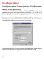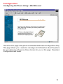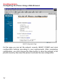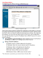
1
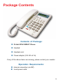
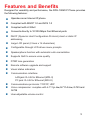
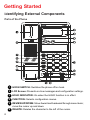
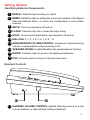
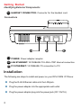
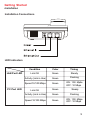
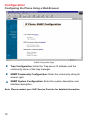
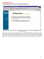
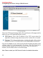
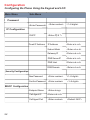
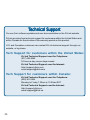
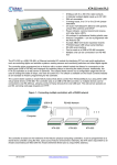
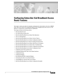
D-Link DPH-100M IP Phone Manual Version 1.10 Building Networks for People Contents Package Contents ................................................................................3 Introduction............................................................................................4 Features and Benefits ...........................................................................5 Getting Started ......................................................................................6 Configuration ......................................................................................10 Additional Features .............................................................................25 Technical Specifications ......................................................................28 Waranty ...............................................................................................30 Registration ........................................................................................33 Contacting Technical Support ..............................................................34 2 Package Contents Contents of Package: D-Link DPH-100M IP Phone Handset Handset cord Power adapter (12V DC at 1A) If any of the above items are missing, please contact your reseller. Operation Requirements: Internet connection (via ISP) Local power outlet 3 Introduction The DPH-100M is a fully featured IP telephone that allows both business and residential customers to benefit from IP telephony services. It reduces costs by providing access to local and long-distance voice and data services over a single network connection. This easy-to-use IP phone plugs directly into a local area network (LAN) through a standard Ethernet jack. The IP phone utilizes 10/100-Mbps Ethernet for connectivity and supports a full range of telephone network features. In addition, it provides access to a host of features for business applications, including hold, mute, and speakerphone operation. The DPH-100M is equipped with a LCD panel for easy configuration and use. 4 Features and Benefits Designed for versatility and performance, the DPH-100M IP Phone provides the following features: Operates as an Internet IP phone Compliant with MGCP 1.0 and NCS 1.0 Compliant with H.323v2 Connects directly to 10/100-Mbps Fast Ethernet ports DHCP (Dynamic Host Configuration Protocol) client or static IP addressing Large LCD panel (2 lines x 16 characters) Configurable through LCD-driven menu prompts Speakerphone function with automatic echo cancellation Supports QoS to ensure voice quality DTMF tone generation Remote software upgrade and support Visual status indicators Communication interface: LAN jack: RJ-45 for Ethernet (MDI-II) PC jack: RJ-45 for Ethernet (MDI-X) Communications protocols: TCIP/IP, UDP User-adjustable volume control Voice compression: complies with 6.711 µ -law,G.711 A-law, G.723 and G.729 5 Getting Started Identifying External Components Parts of the Phone 1 HOOK SWITCH: Switches the phone off/on hook. 2 LCD Screen: Presents on-line messages and configuration settings. 3 HOLD INDICATOR: On when the HOLD function is in effect. 4 FUNCTION: Selects configuration menus. 5 REVIEW UP/DOWN: Move foward and backward through menu items; move the cursor up and down. 6 DELETE: Deletes the character to the left of the cursor. 6 Getting Started Identifying External Components 7 REDIAL: Dials the last number you called. 8 MEMO: Shifts the state to editing the name and number of the Speed Dial and Address Book, or stores the configuration in non-volatile memory. MUTE: Turns sound pickup off and on. 9 10 FLASH: Transfers the call or clears the input string. 11 HOLD: Turns sound transmission and reception off and on. 12 DIAL PAD: 0, 1, 2, 3, 4, 5, 6, 7, 8, 9, *, #. 13 RING/SPEAKER VOLUME CONTROL: Increases or decreases ring volume or speakerphone volume during a call. 14 SPEAKER PHONE: Enables/disables the speakerphone function. 15 ENTER: Confirms input or goes to the displayed submenu. 16 ESC: Cancels input or returns to the previous menu. Handset Controls 17 HANDSET VOLUME CONTROL: Adjusts listening volume on a call to Low, Medium, or High (default setting is Medium). 7 Getting Started Identifying External Components 18 HANDSET CONNECTOR: Connector for the handset cord. Connectors 19 POWER: Power adapter receptor. 20 LAN ETHERNET: 10/100BASE-TX LAN to ITSP Internet connection. 21 PC ETHERNET: 10/100BASE-TX connection to PC. Installation The following are steps to install and power on your DPH-100M IP Phone: Plug the RJ-45 Ethernet cable into the LAN jack. Plug the power adapter into the appropriate wall outlet. Plug the power adapter plug into the power jack (DC 12V/1A). 8 Getting Started Installation Installation Connections LED Indicators LAN Port LED PC Port LED Condition Color Timing Link OK Green Steady Activity (Link in Use) Green Flashing Speed 10/100 Mbps Green ON: 100 Mpbs OFF: 10 Mbps Link OK Green Steady Activity (Link in Use) Green Flashing Speed 10/100 Mbps Green ON: 100 Mbps Mpbs OFF: 10 Mbps 9 Configuration Configuring the Phone Using a Web Browser Setting up the Connection In order to use a Web browser to configure the DPH-100M IP phone, you must make sure the phone has a valid Ethernet connection to a PC or LAN via its Ethernet port. We recommend using a recent version of any widely used browser. The browser must have JavaScript enabled. The phone comes with a default IP address of 10.1.1.100. You must make sure the computer is in the same IP domain as the IP phone. You can do this by changing the IP address of the computer as shown below. Once this is done, run any recent, JavaScript-enabled browser on the computer and point it to the default IP address of the phone as shown below: 10 Configuration Configuring the Phone Using a Web Browser This is the main page of the phone’s embedded Web-based configuration utility. This page shows you a welcome message and information about the phone for your reference. There are three choices for you on this page: Download, Configuration and Reset. 11 Configuration Configuring the Phone Using a Web Browser MGCP Configuration Page On this page you can set the network, security, MGCP, CODEC and clock configuration settings according to your requirements. After completing configuration, you must choose the Save button to store the settings in the phone’s memory, then reset the phone to activate the new configuration. 12 Configuration Configuring the Phone Using a Web Browser Network Configuration Page This is the IP phone network configuration web page. On this page, you can set the network parameters according to your network environment. These include the DHCP option and fixed-IP address/subnet/gateway settings. After adjusting the settings, you must click the Save button to save your new configuration. You can set the phone to get its IP address from a DHCP server or to use a fixed IP address. Using DHCP to get an IP address: When DHCP is chosen, the IP phone will attempt to obtain its IP settings from a DHCP server. Using a fixed IP address: IP Address: Enter a valid IP address for the phone. IP Netmask: Enter the correct subnet mask for the phone. IP Gateway: Enter an IP gateway for the phone. DNS Server: Enter a DNS server IP address.* DNS Host: Enter a DNS server host name.* DNS Domain: Enter a DNS server domain name.* *This information is provided by your Internet Service Provider (ISP). 13 Configuration Configuring the Phone Using a Web Browser Security Configuration Page This is the IP phone’s security password configuration page. It is recommended that you set a password to protect your IP phone’s configuration from unwanted tampering by other users. After changing the setting, you must click the Save button to save your new configuration. The default password shows empty fields for “New password” and “Confirm new password”. 14 Configuration Configuring the Phone Using a Web Browser MGCP Parameter Configuration Page This is the MGCP configuration page. You can set the endpoint domain name, call agent (i.e. the “Notify Entity”) IP address, and the call agent port (the default MGCP port number is 2427). After making any changes, you must click the Save button to save the new configuration. Endpoint Domain Name: This is the endpoint name your IP phone will be known as by the call agent (the default setting is “MGCP”)> Call Agent IP Address: Enter a Call Agent IP address for the IP phone. This IP address is the address of your VoIP Service Provider. Call Agent port: Enter the MGCP Call Agent service port (the default port number is 2427). 15 Configuration Configuring the Phone Using a Web Browser AUDIO/CODEC Configuration Page This is the codec (compression/decompression) configuration page. You can select the voice codecs G.711 µ -law, G.711 A-law, G.723 and G.729 on this page. After configuration, click the Save button. Send Telephone Events via RFC2833 signaling using payload type Enable: Enable RFC2833 out of band DTMF Disable: Disable RFC2833 out of band DTMF When this setting is enabled, the payload type will be used in RFC2833 event. Drop voice packets during RFC2833 Telephone Event packets Enable: Voice packets will not be transmitted when transmitting RFC2833 packets Disable: Voice packets will be transmitted when transmitting RFC2833 packets 16 Configuration Configuring the Phone Using a Web Browser Squelch inband DTMF Audio Enable: Inband DTMF will not be transmitted Disable: Inband DTMF will be transmitted Note: Please contact your VoIP Service Provider for detailed information. Clock Configuration Page This is the clock configuration page. You can specify an NTP (Network Time Protocol) server, select the time zone of your region, and enable or disable adjustment for Daylight Savings Time to ensure that the phone displays the correct local time. After configuration, click the “Save” button. NTP Server IP: Enter the IP address of the NTP server for the phone. The NTP Server IP may be provided by your ISP. Time Zone: Select the appropriate time zone from the scrollable list. 17 Configuration Configuring the Phone Using a Web Browser SNMP Configuration Page Trap Configuration: Enter the Trap server IP address and the community name of the trap manager. SNMP Community Configuration: Enter the community string for access right. SNMP System Configuration: Enter the system description and interface description. Note: Please contact your VoIP Service Provider for detailed information. 18 Configuration Configuring the Phone Using a Web Browser Download Page This page is used to upgrade the phone’s MGCP application software image. When you click this page’s single button, you will be taken to the TFTP download page, and the phone will be restarted in download mode (see below for details). 19 Configuration Configuring the Phone Using a Web Browser TFTP Download Page This is the TFTP download page. Both of the input boxes on this page must be filled in for the TFTP download function to work. TFTP Server: This is the IP address of the TFTP server where the application software image (also known as the “runtime file”) is located. Filename: This is the complete name, including the path, of the runtime image file on your TFTP server that is to be downloaded to the device. Fill in the IP address of your TFTP server and the full path and name of the software image file to be downloaded to the phone. Click Start Download to make the phone request the file from the server. When the download is finished, click the Reset button on the Reset page. Note: Please contact your VoIP Service Provider for detailed information. 20 Configuration Configuring the Phone Using a Web Browser Reset Page This is the IP phone reset system web page. You can reset the IP phone device through the web browser by clicking the “Reset” button. Configuring the Phone Using the Keypad and LCD After power is applied, the LCD panel will display the time on the first line and the phone’s name on the second line. To configure the phone, press the Function button, enter the password if one is set, and then press the Enter key. (The default password is Null <Empty>.) After successful password authentication, menu names will be displayed on the LCD panel, and you can step through them by pressing Review Tor S. Press the Enter button to access the named menu and modify the settings in it; press the ESC button to exit any menu but the main menu. The Function menu is hierarchical and similar to the Web page configuration, as shown below. 21 Configuration Configuring the Phone Using the Keypad and LCD Main Menu Sub-Menu Password <Enter Password> <Enter number> <1~8 digits> <1~8 digits> <1~8 digits> IP Configuration DHCP <Enter LK # *> IP Address <Enter a.b.c.d> Subnet Mask <Enter a.b.c.d> Gateway IP <Enter a.b.c.d> DNS Server IP <Enter a.b.c.d> DNS Host <Enter a.b.c.d> DNS Domain <Enter a.b.c.d> New Password <Enter number> <1~8 digits> Confirm Password <Enter number> <1~8 digits> Endpoint Name <Enter string> Call Agent IP <Enter a.b.c.d> Call Agent Port <Enter number> Fixed IP Address Security Configuration MGCP Configuration 22 <Default: 2427> <1~20 digits> <Enter number> Configuration Configuring the Phone Using the Keypad and LCD Codec Configuration None (Use default <Enter> G.711codec) G.723(G.711+G.723) <Enter> G.729(G.711+G.729) <Enter> Clock Configuration NTP Server address <Enter a.b.c.d> Time Zone Daylight Saving <Enter LK # *> Enable <Enter LK # *> Disable <Enter LK # *> After changing the settings, press “MEMO” to store the changes in the phone’s non-volatile memory, or the changes will disappear after a power reset. Note: The key buttons behave as shown below only when the configuration menu is active. (To activate the keypad configuration menu, press button <FUNCTION>.) 23 Configuration Configuring the Phone Using the Keypad and LCD FUNCTION: Inactivates the configuration menu. MEMO: Stores the configuration back to the Flash. FLASH: Clears user input string and resets the cursor to the beginning. DELETE: Deletes user input character; same as <Back Space>. REVIEW Enter <#>: Goes to the submenu or confirms user input. ESC <*>: Return to the upper menu or to ignore user input. T 24 : Scrolls menu items or option items. Additional Features Redial The IP phone remembers the last phone number dialed. To dial the same number again, take the handset off the hook or press the SPEAKER PHONE button, listen for a dial tone, and then press the REDIAL button. Memo Allows you to edit the names and numbers of the Speed Dial & Address Book. Edit Speed Dial Address Book And Make a Call via Speed Dial: Making a Call via Speed Dial Normal Key[1~10] * Display information For the Index Key[1~10] Off hook On hook Redial MEMO Calling Edit Name 25 Additional Features Memo Editing Speed Dial Addresses On Hook * Select Index * Key[1~10] Edit Name MEMO [1~10] * # Edit Number [1~10] MEMO 26 # Additional Features Mute Disables the voice packet transmission to the phone’s network interface. To enable/disable MUTE, press the MUTE button during a call. Flash Flash to transfer the call. To transfer the call, simply press the FLASH button. Hold Press the HOLD button to hold a call and press it again to release. Speakerphone Use to dial or talk without picking up the handset. To take advantage of the speakerphone, first press the Speaker Phone button and make sure the IN USE LED lights up. Next, enter the destination phone number via the dialing pad. Press the Speaker Phone button again when finished with the call. 27 Technical Specifications Call Control Protocols Compliance MGCP, H.323 Internet Protocol Compliance TCP/IP, UDP, ARP, TFTP, ICMP, Telnet, HTTP Available Audio Compression Schemes G.711 µ-law, G.711 A-law, G.723, G.729 Single Format: DTMF Echo Cancellation: G.165 DTMF tone detection/generation IEEE 802.3 10BASE-T Ethernet compliant IEEE 802.3u 100BASE-TX Ethernet compliant LEDs LAN: 10/100M, Link/Act PC: 10/100M, Link/Act Dimensions 162 mm (W) x 223 mm (D) x 82 mm (H) Number of Ports Two RJ-45 Ports: PC: NWay 10/100BASE-TX Fast Ethernet port (MDI-X) LAN: NWay 10/100BASE-TX Fast Ethernet port (MDI-II) Power Supply 28 AC-to-DC power adapter (provided) DC Input: 12VDC/1A Technical Specifications Operating Temperature 0 - 50 °C Storage Temperature -10 - 55 °C Humidity 5% - 95% non-condensing Safety UL/CUL Emission (EMI) FCC Class B CE Class B 29 Subject to the terms and conditions set forth herein, D-Link Systems, Inc. (“D-Link”) provides this Limited warranty for its product only to the person or entity that originally purchased the product from: • • D-Link or its authorized reseller or distributor and Products purchased and delivered within the fifty states of the United States, the District of Columbia, U.S. Possessions or Protectorates, U.S. Military Installations, addresses with an APO or FPO. Limited Warranty: D-Link warrants that the hardware portion of the D-Link products described below will be free from material defects in workmanship and materials from the date of original retail purchase of the product, for the period set forth below applicable to the product type (“Warranty Period”), except as otherwise stated herein. 1-Year Limited Warranty for the Product(s) is defined as follows: • • • Hardware (excluding power supplies and fans) One (1) Year Power Supplies and Fans One (1) Year Spare parts and spare kits Ninety (90) days D-Link’s sole obligation shall be to repair or replace the defective Hardware during the Warranty Period at no charge to the original owner or to refund at D-Link’s sole discretion. Such repair or replacement will be rendered by D-Link at an Authorized D-Link Service Office. The replacement Hardware need not be new or have an identical make, model or part. D-Link may in its sole discretion replace the defective Hardware (or any part thereof) with any reconditioned product that D-Link reasonably determines is substantially equivalent (or superior) in all material respects to the defective Hardware. Repaired or replacement Hardware will be warranted for the remainder of the original Warranty Period from the date of original retail purchase. If a material defect is incapable of correction, or if D-Link determines in its sole discretion that it is not practical to repair or replace the defective Hardware, the price paid by the original purchaser for the defective Hardware will be refunded by D-Link upon return to D-Link of the defective Hardware. All Hardware (or part thereof) that is replaced by D-Link, or for which the purchase price is refunded, shall become the property of D-Link upon replacement or refund. Limited Software Warranty: D-Link warrants that the software portion of the product (“Software”) will substantially conform to D-Link’s then current functional specifications for the Software, as set forth in the applicable documentation, from the date of original retail purchase of the Software for a period of ninety (90) days (“Warranty Period”), provided that the Software is properly installed on approved hardware and operated as contemplated in its documentation. D-Link further warrants that, during the Warranty Period, the magnetic media on which D-Link delivers the Software will be free of physical defects. D-Link’s sole obligation shall be to replace the non-conforming Software (or defective media) with software that substantially conforms to D-Link’s functional specifications for the Software or to refund at D-Link’s sole discretion. Except as otherwise agreed by D-Link in writing, the replacement Software is provided only to the original licensee, and is subject to the terms and conditions of the license granted by D-Link for the Software. Software will be warranted for the remainder of the original Warranty Period from the date or original retail purchase. If a material non-conformance is incapable of correction, or if D-Link determines in its sole discretion that it is not practical to replace the nonconforming Software, the price paid by the original licensee for the non-conforming Software will be refunded by D-Link; provided that the non-conforming Software (and all copies thereof) is first returned to D-Link. The license granted respecting any Software for which a refund is given automatically terminates. Non-Applicability of Warranty: The Limited Warranty provided hereunder for hardware and software of D-Link’s products will not be applied to and does not cover any refurbished product and any product purchased through the inventory clearance or liquidation sale or other sales in which D-Link, the sellers, or the liquidators expressly disclaim their warranty obligation pertaining to the product and in that case, the product is being sold “As-Is” without any warranty whatsoever including, without limitation, the Limited Warranty as described herein, notwithstanding anything stated herein to the contrary. 30 Submitting A Claim: The customer shall return the product to the original purchase point based on its return policy. In case the return policy period has expired and the product is within warranty, the customer shall submit a claim to D-Link as outlined below: • The customer must submit with the product as part of the claim a written description of the Hardware defect or Software nonconformance in sufficient detail to allow D-Link to confirm the same. • The original product owner must obtain a Return Material Authorization (“RMA”) number from the Authorized D-Link Service Office and, if requested, provide written proof of purchase of the product (such as a copy of the dated purchase invoice for the product) before the warranty service is provided. • After an RMA number is issued, the defective product must be packaged securely in the original or other suitable shipping package to ensure that it will not be damaged in transit, and the RMA number must be prominently marked on the outside of the package. Do not include any manuals or accessories in the shipping package. D-Link will only replace the defective portion of the Product and will not ship back any accessories. • The customer is responsible for all in-bound shipping charges to D-Link. No Cash on Delivery (“COD”) is allowed. Products sent COD will either be rejected by D-Link or become the property of D-Link. Products shall be fully insured by the customer and shipped to D-Link Systems, Inc., 17595 Mt. Herrmann, Fountain Valley, CA 92708. D-Link will not be held responsible for any packages that are lost in transit to D-Link. The repaired or replaced packages will be shipped to the customer via UPS Ground or any common carrier selected by D-Link, with shipping charges prepaid. Expedited shipping is available if shipping charges are prepaid by the customer and upon request. D-Link may reject or return any product that is not packaged and shipped in strict compliance with the foregoing requirements, or for which an RMA number is not visible from the outside of the package. The product owner agrees to pay D-Link’s reasonable handling and return shipping charges for any product that is not packaged and shipped in accordance with the foregoing requirements, or that is determined by D-Link not to be defective or non-conforming. What Is Not Covered: This limited warranty provided by D-Link does not cover: Products, if in D-Link’s judgment, have been subjected to abuse, accident, alteration, modification, tampering, negligence, misuse, faulty installation, lack of reasonable care, repair or service in any way that is not contemplated in the documentation for the product, or if the model or serial number has been altered, tampered with, defaced or removed; Initial installation, installation and removal of the product for repair, and shipping costs; Operational adjustments covered in the operating manual for the product, and normal maintenance; Damage that occurs in shipment, due to act of God, failures due to power surge, and cosmetic damage; Any hardware, software, firmware or other products or services provided by anyone other than DLink; Products that have been purchased from inventory clearance or liquidation sales or other sales in which D-Link, the sellers, or the liquidators expressly disclaim their warranty obligation pertaining to the product. Repair by anyone other than D-Link or an Authorized D-Link Service Office will void this Warranty. Disclaimer of Other Warranties: EXCEPT FOR THE LIMITED WARRANTY SPECIFIED HEREIN, THE PRODUCT IS PROVIDED “AS-IS” WITHOUT ANY WARRANTY OF ANY KIND WHATSOEVER INCLUDING, WITHOUT LIMITATION, ANY WARRANTY OF MERCHANTABILITY, FITNESS FOR A PARTICULAR PURPOSE AND NON-INFRINGEMENT. IF ANY IMPLIED WARRANTY CANNOT BE DISCLAIMED IN ANY TERRITORY WHERE A PRODUCT IS SOLD, THE DURATION OF SUCH IMPLIED WARRANTY SHALL BE LIMITED TO NINETY (90) DAYS. EXCEPT AS EXPRESSLY COVERED UNDER THE LIMITED WARRANTY PROVIDED HEREIN, THE ENTIRE RISK AS TO THE QUALITY, SELECTION AND PERFORMANCE OF THE PRODUCT IS WITH THE PURCHASER OF THE PRODUCT. Limitation of Liability: TO THE MAXIMUM EXTENT PERMITTED BY LAW, D-LINK IS NOT LIABLE UNDER ANY CONTRACT, NEGLIGENCE, STRICT LIABILITY OR OTHER LEGAL OR EQUITABLE THEORY FOR ANY LOSS OF USE OF THE PRODUCT, INCONVENIENCE OR DAMAGES OF ANY CHARACTER, WHETHER DIRECT, SPECIAL, INCIDENTAL OR CONSEQUENTIAL (INCLUDING, BUT NOT LIMITED TO, DAMAGES FOR LOSS OF GOODWILL, LOSS OF REVENUE OR PROFIT, WORK STOPPAGE, COMPUTER FAILURE OR MALFUNCTION, FAILURE OF OTHER EQUIPMENT OR COMPUTER PROGRAMS TO WHICH DLINK’S PRODUCT IS CONNECTED WITH, LOSS OF INFORMATION OR DATA CONTAINED IN, STORED ON, OR INTEGRATED WITH ANY PRODUCT RETURNED TO D-LINK FOR WARRANTY SERVICE) RESULTING FROM THE USE OF THE PRODUCT, RELATING TO WARRANTY SERVICE, OR ARISING OUT OF ANY BREACH OF THIS LIMITED WARRANTY, EVEN IF D-LINK HAS BEEN ADVISED OF THE POSSIBILITY OF SUCH DAMAGES. THE SOLE REMEDY FOR A BREACH OF THE FOREGOING LIMITED WARRANTY IS 31 REPAIR, REPLACEMENT OR REFUND OF THE DEFECTIVE OR NON-CONFORMING PRODUCT. THE MAXIMUM LIABILITY OF D-LINK UNDER THIS WARRANTY IS LIMITED TO THE PURCHASE PRICE OF THE PRODUCT COVERED BY THE WARRANTY. THE FOREGOING EXPRESS WRITTEN WARRANTIES AND REMEDIES ARE EXCLUSIVE AND ARE IN LIEU OF ANY OTHER WARRANTIES OR REMEDIES, EXPRESS, IMPLIED OR STATUTORY Governing Law: This Limited Warranty shall be governed by the laws of the State of California. Some states do not allow exclusion or limitation of incidental or consequential damages, or limitations on how long an implied warranty lasts, so the foregoing limitations and exclusions may not apply. This limited warranty provides specific legal rights and the product owner may also have other rights which vary from state to state. Trademarks: D-Link is a registered trademark of D-Link Systems, Inc. Other trademarks or registered trademarks are the property of their respective manufacturers or owners. Copyright Statement: No part of this publication or documentation accompanying this Product may be reproduced in any form or by any means or used to make any derivative such as translation, transformation, or adaptation without permission from D-Link Corporation/D-Link Systems, Inc., as stipulated by the United States Copyright Act of 1976. Contents are subject to change without prior notice. Copyright© 2002 by D-Link Corporation/D-Link Systems, Inc. All rights reserved. CE Mark Warning: This is a Class B product. In a domestic environment, this product may cause radio interference, in which case the user may be required to take adequate measures. FCC Statement: This equipment has been tested and found to comply with the limits for a Class B digital device, pursuant to part 15 of the FCC Rules. These limits are designed to provide reasonable protection against harmful interference in a residential installation. This equipment generates, uses, and can radiate radio frequency energy and, if not installed and used in accordance with the instructions, may cause harmful interference to radio communication. However, there is no guarantee that interference will not occur in a particular installation. If this equipment does cause harmful interference to radio or television reception, which can be determined by turning the equipment off and on, the user is encouraged to try to correct the interference by one or more of the following measures: • • • • Reorient or relocate the receiving antenna. Increase the separation between the equipment and receiver. Connect the equipment into an outlet on a circuit different from that to which the receiver is connected. Consult the dealer or an experienced radio/TV technician for help. For detailed warranty outside the United States, please contact corresponding local D-Link office. 32 Registration Register online your D-Link product at http://support.dlink.com/register/ 33 Techni cal Support echnical You can find software updates and user documentation on the D-Link website. D-Link provides free technical support for customers within the United States and within Canada for the duration of the warranty period on this product. U.S. and Canadian customers can contact D-Link technical support through our website, or by phone. Tech Support for customers within the United States: D-Link Technical Support over the Telephone: (877) 453-5465 24 hours a day, seven days a week. D-Link Technical Support over the Internet: http://support.dlink.com email:support@dlink.com Tech Support for customers within Canada: D-Link Technical Support over the Telephone: (800) 361-5265 Monday to Friday 7:30am to 12:00am EST D-Link Technical Support over the Internet: http://support.dlink.ca email:support@dlink.ca 34