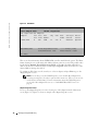
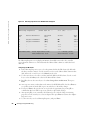
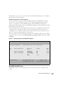
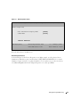
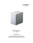
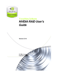
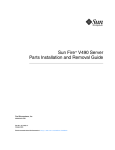
1
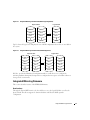
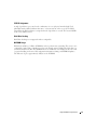
Dell™ PowerEdge™ Expandable RAID Controller 4/IM
Integrated RAID
User’s Guide
Model PERC 4/IM
www.dell .com | support.dell.com
____________________
Information in this document is subject to change without notice.
© 2004 Dell Inc. All rights reserved.
Reproduction in any manner whatsoever without the written permission of Dell Inc. is strictly forbidden.
Trademarks used in this text: Dell, the DELL logo and PowerEdge are trademarks of Dell Inc. Microsoft, Windows NT, MS-DOS,
and Windows are registered trademarks of Microsoft Corporation. LSI Logic, Fusion-MPT, and Integrated Mirroring, are
trademarks or registered trademarks of LSI Logic Corporation.
Other trademarks and trade names may be used in this document to refer to either the entities claiming the marks and names or
their products. Dell Inc. disclaims any proprietary interest in trademarks and trade names other than its own.
Model PERC 4/IM
October 2004
P/N W7487
Rev. A00
Preface
This user’s guide explains how to configure and use the components of the Dell PERC 4/IM
(Integrated Mirroring™) RAID Controller on the Dell PowerEdge 1855.
Audience
This user’s guide assumes that you have some familiarity with installing and configuring software
programs and that you are familiar with computer storage devices in general. The people who benefit
from this document are end users who are using the IM software product to configure mirrored
volumes.
Organization
This document has the following chapters:
Chapter 1, Introduction to Integrated RAID, provides an overview of Integrated RAID, its features,
and its benefits.
Chapter 2, Integrated Mirroring Overview, provides an overview of the IM feature.
Chapter 3, Setting Up Integrated Mirroring, describes how to set up IM using the BIOS-based
configuration utility.
Conventions Used in This Manual
The first time a word or phrase is defined in this manual, it is italicized.
Hexadecimal numbers are indicated by the prefix “0x” —for example, 0x32CF. Binary numbers are
indicated by the prefix “0b” —for example, 0b0011.0010.1100.1111.
Contents
1 Introduction to Integrated RAID
Introduction .
. . . . . . . . . . . . . . . . . . . . . . . . . . . . . . .
Integrated RAID Benefits and Features
Using this Manual
7
. . . . . . . . . . . . . . . . . . .
7
. . . . . . . . . . . . . . . . . . . . . . . . . . . . .
7
2 Integrated Mirroring Overview
Introduction .
Features .
. . . . . . . . . . . . . . . . . . . . . . . . . . . . . . .
9
. . . . . . . . . . . . . . . . . . . . . . . . . . . . . . . . .
9
Description
. . . . . . . . . . . . . . . . . . . . . . . . . . . . . . . .
Integrated Mirroring Firmware .
. . . . . . . . . . . . . . . . . . . . . .
Host Interface . . . . . . . . . . . . . . . . . . .
Resynchronization with Concurrent Host I/O Operation
Metadata Support . . . . . . . . . . . . . . . . . .
Hot Swap . . . . . . . . . . . . . . . . . . . . . .
SMART Support . . . . . . . . . . . . . . . . . . .
Media Verification . . . . . . . . . . . . . . . . .
SCSI ID Assignment . . . . . . . . . . . . . . . . .
Disk Write Caching . . . . . . . . . . . . . . . . .
NVSRAM Usage . . . . . . . . . . . . . . . . . .
10
11
. . . . . . . . .
11
12
12
12
12
12
13
13
13
. . . . . . . . . . . . . . . . . . . . . . . .
15
. . . . . . . . .
. . . . . . . . .
. . . . . . . . .
. . . . . . . . .
. . . . . . . . .
. . . . . . . . .
. . . . . . . . .
. . . . . . . . .
3 Setting Up Integrated Mirroring
IM Configuration Overview .
Configuring IM with the BIOS-Based CU
. . . . . . . . . . . . . . . . . .
Configuration Screen Overview . . .
Quick IM Configuration Procedure . .
Detailed IM Configuration Procedure.
Other BIOS-Based CU Screens . . .
How to... .
15
. . . . . . . . . . . . . . . . .
15
16
17
21
. . . . . . . . . . . . . . . . . . . . . . . . . . . . . . . . .
24
...Configure RAID-1/IM
. . . . . . . . . . . . . . . . .
. . . . . . . . . . . . . . . . .
. . . . . . . . . . . . . . . . .
. . . . . . . . . . . . . . . . . . . . . . . .
24
Contents
5
...Switch from IM to SCSI Mode . . . .
...Switch from SCSI to IM Mode . . . .
...Clone the OS Using the IM Controller .
...Upgrade to a Larger Volume . . . . .
Troubleshooting
6
Contents
. . . . . . . . . . . . . . . .
24
25
25
25
. . . . . . . . . . . . . . . . . . . . . . . . . . . . . .
25
. . . . . . . . . . . . . . . .
. . . . . . . . . . . . . . . .
. . . . . . . . . . . . . . . .
1
Introduction to Integrated RAID
This chapter provides an overview of Integrated RAID, its features, and its benefits. The chapter
includes these sections:
•
"Introduction" on page 7
•
"Integrated RAID Benefits and Features" on page 7
•
"Using this Manual" on page 7
Introduction
The Dell, Inc. Integrated RAID solution provides cost benefits for the server market where the
extra performance, storage capacity, and/or redundancy of a RAID configuration are required. The
solution is based on the Integrated Mirroring (IM) mode, which provides features of RAID-1, and
Embedded SCSI mode.
Integrated RAID Benefits and Features
•
Low cost single-volume RAID fills the needs of most internal RAID installations
•
Easy to use - installation and configuration are not complex
•
System can boot from an IM volume
•
No special OS-specific software required
•
High reliability and data integrity
•
Non-volatile write journaling
•
Physical disks not visible to OS or to application software
•
Low host CPU and PCI bus utilization
•
Fusion-MPT architecture provides processing power
•
160 MHz ARM966 processors provide maximum processing capacity
•
Shared memory architecture minimizes external memory requests
•
Functionality is contained in device hardware and firmware
Using this Manual
•
Chapters 2 and 3 of this User’s Guide explain how to configure an IM volume.
Introduction to Integrated RAID
7
w w w. d el l. c om | s upp ort . del l . com
•
8
Refer to the platform User’s Guide on http://support.dell.com for platform-specific
information.
Introduction to Integrated RAID
2
Integrated Mirroring Overview
This chapter provides an overview of the IM feature and includes these sections:
•
"Introduction" on page 9
•
"Features" on page 9
•
"Description" on page 10
•
"Integrated Mirroring Firmware" on page 11
Introduction
The IM feature provides simultaneous mirroring on a configuration of two disks, to assure fault
tolerant, high availability data. If a disk fails, the hot swap capability allows the system to be easily
restored by simply hot swapping disks. The system then automatically re-mirrors the swapped disk.
Features
This section lists the key features of IM.
•
Supports configurations of two mirrored disks
•
Mirrored volume runs in optimal mode or degraded mode (if one mirrored disk fails)
•
Provides hot swap capability
•
Presents a single virtual drive to the OS
•
Supports disks of different types and capacities
•
Fusion-MPT architecture encompasses firmware, multiple physical interfaces, and supporting
OS-level drivers
•
Uses BIOS-based configuration utility to select IM or SCSI mode
•
Provides error notification through OS-specific event log
•
Provides management of IM under Operating Systems through OpenManage Storage
Services (OMSS). Additional information can be found in the OMSS User Guide on
http://support.dell.com.
•
Supports SAF-TE drive status LEDs for IM disks
•
Write journaling allows automatic synchronization of potentially inconsistent data after
unexpected power-down situations
•
Uses metadata to store volume configuration on mirrored disks
Integrated Mirroring Overview
9
w w w. d el l. c om | s upp ort . del l . com
•
Provides automatic background resynchronization while host I/Os continue
•
Supports media verification
Description
The IM feature provides mirroring for the boot volume, as shown in Figure 2-1. This is
accomplished through the firmware of a PERC 4/IM controller that supports the standard FusionMPT interface. The runtime mirroring of the boot disk is transparent to the BIOS, drivers, and
operating system. Host-based status software monitors the state of the mirrored disks and reports
any error conditions. In Figure 2-1, the system is configured with a second disk as a mirror of the
first (primary) disk.
Figure 2-1.
Typical Mainboard Implementation
Two Disk Drives
Internal
SCSI
OS
Mirrored
OS
NVSRAM
(For Write Journaling)
PERC 4/IM
Controller
Memory
Bus
EEPROM
(For Configuration)
Figure 2-2 shows the logical view and physical view of the mirroring configuration when there are
two disks in the mirrored volume.
10
Integrated Mirroring Overview
Figure 2-2.
Integrated Mirroring with Two Disks (Mirroring Configuration)
Physical View
LBA 1
LBA 2
+
LBA 3
LBA N
Logical View
LBA 1’
LBA 1
LBA 2’
LBA 2
LBA 3’
LBA 3
LBA N’
LBA N
Fig 2-3 shows the logical view and physical view of SCSI configuration when there are two disks in
the system.
Figure 2-3.
Integrated Mirroring with Two Disks (SCSI Configuration)
Physical View
Logical View
LBA 1
LBA x
LBA 1
LBA 2
LBA x
LBA 2
LBA 3
LBA x
LBA 3
LBA N
LBA N
LBA N
LBA x
LBA x
+
LBA x
LBA N’
Dell, Inc. provides the BIOS-based configuration utility to enable the user to configure the
mirroring attributes during initial setup and to reconfigure them in response to hardware failures or
changes in the environment.
Integrated Mirroring Firmware
This section describes features of the PERC 4/IM firmware.
Host Interface
Through the Fusion-MPT interface, the host OS has access to the logical IM drive as well as the
physical disks. This allows support for domain validation and Ultra320 SCSI expander
configuration.
Integrated Mirroring Overview
11
w w w. d el l. c om | s upp ort . del l . com
Resynchronization with Concurrent Host I/O Operation
Resynchronization is attempted after the firmware has been reset, or after a “hot swap” has
occurred to one of the physical IM disks.
The IM volume can be partially resynchronized, if the logging information in NVSRAM indicates
that this is necessary. It usually takes less than a second for the firmware to complete a partial
resynchronization. Like full synchronization, partial resynchronization is performed in the
background.
Metadata Support
Metadata is the data on each member disk describing the IM logical drive configuration. When the
firmware is initialized, each member disk is queried to read the stored metadata for consistency
checking. The usable disk space for each IM member disk is adjusted down to leave room for this
data.
Hot Swap
The IM firmware supports hot swapping. The hot-swapped disk is automatically resynchronized in
the background, without any host or user intervention. The hot swapped disk must be at the same
physical SCSI ID as one of the physical disks configured in the IM volume. The firmware detects
“hot swap” removal and disk insertion.
Following a “hot swap” event, the firmware readies the new physical disk by spinning it up and
verifying that it has enough capacity for the IM volume. The IM firmware resynchronizes all hot
swapped disks that have been removed, even if the same disk is re-inserted. In a two-disk mirrored
volume, the IM firmware marks the hot-swapped disk as the secondary disk and marks the other
mirrored disk as the primary disk. The firmware resynchronizes all data from the primary disk onto
the new secondary disk.
SMART Support
The IM firmware enables Mode 6 SMART on the IM member disks. Mode 6 SMART requires each
physical disk to be polled once per minute. If a SMART ASC/ASCQ code is detected on a physical
IM disk, the firmware processes the SMART data, and the last received SMART ASC/ASCQ is
stored in non-volatile memory. The IM volume does not support SMART directly, since it is just a
logical representation of the physical disks in the volume.
Media Verification
The IM firmware supports a background media verification feature that runs once per minute when
the IM volume is in optimal mode. The media verification feature issues a SCSI Verify command
to a segment of the disk. If the command fails for any reason, the other disk’s data for this segment
is read and written to the failing disk in an attempt to refresh the data. The current Media
Verification Logical Block Address is written to non-volatile memory occasionally to allow Media
Verification to continue approximately where it left off prior to a power-cycle.
12
Integrated Mirroring Overview
SCSI ID Assignment
A single logical drive is presented as the combination of a set of physical member disks. Each
individual member disk is hidden and returns a “selection timeout” when accessed. The SCSI
Target ID of the IM logical drive is assigned when the logical drive is created. The lowest SCSI ID
of the selected disks is used.
Disk Write Caching
Disk Write Caching is not supported and not configurable.
NVSRAM Usage
IM firmware utilitizes a 32 Kbyte NVSRAM in order to perform write journaling. This is not a userconfigurable setting. Write journaling is used to verify that the mirrored disks in the IM volume are
synchronized with each other. The NVSRAM also stores additional code and data used for error and
exception handling, and it stores IM configuration information during serial EEPROM updates.
The disk write log uses approximately 4 Kbytes of the NVSRAM.
Integrated Mirroring Overview
13
14
Integrated Mirroring Overview
w w w. d el l. c om | s upp ort . del l . com
3
Setting Up Integrated Mirroring
This chapter describes how to set up IM using the BIOS-based configuration utility (CU). The
chapter includes these topics:
•
"IM Configuration Overview" on page 15
•
"Configuring IM with the BIOS-Based CU" on page 15
•
"How to..." on page 24
•
"Troubleshooting" on page 25
IM Configuration Overview
The following constraints were made in order to simplify the IM configuration:
•
The BIOS-based CU allows you to create one mirrored volume per PERC 4/IM controller.
•
Disks in an IM volume must be qualified by Dell to provide support for this platform.
•
Disks of different size are allowed in mirrored volumes, but the smallest disk determines the
“logical” size of each disk in the volume. The excess space of larger member disks is not used.
Configuring IM with the BIOS-Based CU
The BIOS-based CU is part of the Fusion-MPT BIOS. When the BIOS loads during boot and you
see the message about the BIOS Configuration Utility, press Ctrl-M to start the utility. After you
do this, the message changes to:
“Please wait, invoking LSI Logic Configuration Utility...”
Configuration Screen Overview
All of the BIOS-based CU screens are partitioned into the areas shown in Figure 3-1 on page 16.
Setting Up Integrated Mirroring
15
w w w. d el l. c om | s upp ort . del l . com
Figure 3-1.
Screen Field Definitions
Header Area
Menu Area
Main Area
Footer Area
•
Header Area: Shows the product title and version.
•
Menu Area: Shows the currently defined menu, if any. Press F2 to move to the menu area.
Select a menu item by moving the cursor to it with the right and left arrow keys and then
pressing Enter.
•
Main Area: Shows information about the PERC 4/IM controllers and attached devices. Some
of the characteristics can be configured. You can scroll horizontally and vertically to view and
select items that do not fit on one screen. Horizontal and vertical scroll bars are displayed
here.
•
Footer Area: Lists the valid keys that invoke actions. Items that allow you to change their
value have square brackets enclosing the value. Items that allow you to “execute an action”
are enclosed by angle brackets.
Quick IM Configuration Procedure
Follow the steps below to configure an IM volume with the BIOS-based CU. For a more complete
explanation of this procedure, including detailed descriptions of the configuration screens, see
"Detailed IM Configuration Procedure" on page 17.
The configuration procedure assumes that the system has hard disks. You can configure one IM
volume per blade.
16
1
On the Main menu screen of the BIOS-based CU, use the arrow keys to select an adapter.
2
Press Enter to go to the Adapter Properties screen.
3
On the Adapter Properties screen, use the arrow keys to select Mirroring Properties.
4
Press Enter to go to the Mirroring Properties screen. Continue with step 5 to configure a twodisk mirrored volume.
5
To configure a two-disk mirrored volume:
Setting Up Integrated Mirroring
a
In the Mirroring Properties screen, select the primary disk for the IM volume (the disk
with the data you want to mirror). Use the arrow keys to move to the Mirrored Pair
column for this disk, and use the + and - keys to select Primary as the value.
b
Use the arrow keys to select the secondary (mirrored) disk for the IM volume. Use the +
and - keys to select Secondary as the value for the Mirrored Pair column.
c
Press Esc, then use the arrow keys to select Save changes then exit this menu. Then press
Enter.
d
A message now warns you that data on the mirrored or SCSI disks will be lost. Press Enter
to accept data erasure from the disk, or press any other key to discard the changes.
e
If you press Enter in Step 5d, the next screen provides an opportunity (by pressing F3) to
confirm that data loss is OK. Or, press any other key to discard the changes.
f
After pressing F3, you are returned to the Main menu. To verify the change in mirroring
properties, use the arrow keys to select an adapter. Then press Enter to return to the
Adapter Properties screen.
g
Use the arrow keys to select Mirroring Properties, and press Enter.
The IM volume exists as soon as you save the changes, and the Mirroring Properties screen displays
the IM volume properties and status.
Detailed IM Configuration Procedure
This section provides more detail on the BIOS-based CU screens that are used to configure an IM
volume. See "Other BIOS-Based CU Screens" on page 21 for descriptions of the other BIOS-based
CU screens that are not used for this task.
NOTE: Your system may have a different version of the Fusion-MPT BIOS. Therefore, the
screens that you see may be slightly different from the examples shown here.
Main Menu
Figure 3-2 shows an example of the Main menu that appears when the BIOS-based CU starts.
Setting Up Integrated Mirroring
17
w w w. d el l. c om | s upp ort . del l . com
Figure 3-2.
Main Menu
PERC 4/IM| LSI Logic MPT SCSI Setup Utility Version MPTBIOS-IM-5.08.06
<Boot Adapter List>
<Global Properties>
LSI Logic Host Bus Adapters
Adapter
PCI
Bus
Dev/ Port
IRQ
Func Number
NVM
Boot
Order
LSI Logic
Control
Mirror
Status
<1020/1030
0
A0>
Yes
0
Enabled
Optimal
Esc=Abort/Exit
6100
15
Arrow Keys=Select Item
-/+ = Change [Item]
Home/End=Select Item
Enter=Execute <Item>
F2 =Menu
This screen shows information about all PERC 4/IM controllers installed in the system. The Mirror
Status column gives an overall status of the Mirrored volume, after it is created. The possible values
for this field are Optimal, Degraded, Resyncing, Failed, or No value. No value, indicated by a
dash, means there is no mirrored volume on this adapter. Degraded usually means that one of the
mirrored disks is missing or has failed.
To configure an IM volume, use the arrow keys to select an adapter, and press Enter to go to the
Adapter Properties screen.
NOTE: You can also access the Global Properties screen and the Boot Adapter List
screen by pressing F2 to select these options in the menu area. (These screens are not
used to define an IM volume.) For more information about the Global Properties
screen or the Boot Adapter List screen, see "Other BIOS-Based CU Screens" on
page 21.
Adapter Properties Screen
You access the Adapter Properties screen by selecting one of the adapters from the Main menu
screen (Figure 3-2). Figure 3-3 shows an example of the Adapter Properties screen.
18
Setting Up Integrated Mirroring
Figure 3-3.
Adapter Properties Screen
PERC 4/IM | LSI Logic MPT SCSI Setup Utility Version MPTBIOS-IM-5.08.06
Adapter Properties
Adapter
PCI
Bus
Dev/
Func
1020/1030
0
A0
<Device Properties>
<Mirroring Properties>
Host SCSI ID
SCSI Bus Scan Order
Removable Media Support
CHS Mapping
Spinup Delay (Secs)
Secondary Cluster Server
Termination Control
<Restore Defaults>
Esc=Abort/Exit
<Synchronize Whole Mirror>
[7]
[Low to High (0.. Max)]
[None]
[SCSI Plug and Play Mapping]
[2]
[No]
[Auto]
Arrow Keys=Select Item -/+ = Change [Item]
Home/End=Select Item
Enter=Execute <Item>
After an IM volume is configured, you can select Synchronize Whole Mirror on the Adapter
Properties screen to force a resynchronization of all blocks in the IM volume. The default is to
resynchronize only the blocks that are out of sync in the volume, as indicated by log entries.
NOTE: The following options are not supported and/or not configurable on this
platform: Secondary Cluster Server; CHS Mapping; Removable Media Support; Host
SCSI ID
On the Adapter Properties screen, use the arrow keys to select Mirroring Properties and then press
Enter to go to the Mirroring Properties screen, which is shown in Figure 3-4.
Mirroring Properties Screen
Figure 3-4 shows the Mirroring Properties screen as it appears before an IM volume is configured.
Setting Up Integrated Mirroring
19
w w w. d el l. c om | s upp ort . del l . com
Figure 3-4.
Mirroring Properties Screen: No IM Volume Configured
PERC 4/IM | LSI Logic MPT SCSI Setup Utility Version MPTBIOS-IM-5.08.06
Mirroring Properties
Volume SCSI ID: --
Size (MB): ------
SCSI
ID
Device Identifier
Mirrored
Pair
Status
Size
(MB)
0
Seagate xxxxxxxxx
[No]
OK
34678
1
Seagate xxxxxxxxx
[No]
OK
34678
2
-
---
----
-----
3
-
---
----
-----
4
-
---
----
-----
Esc=Abort/Exit
Arrow Keys=Select Item
-/+ = Change [Item]
Home/End=Select Item
Enter=Execute <Item>
The Mirroring Properties screen displays information about disks connected to the controller
selected from the Main screen. The fields under the Mirrored Pair column are enabled for hard
disks only.
Configuring an IM volume
20
1
In the Mirroring Properties screen, select the primary disk for the IM volume (the disk with
the data you want to mirror). Use the arrow keys to move to the Mirrored Pair column for this
disk, and use the + and - keys to select Primary as the value.
2
Use the arrow keys to select the secondary (mirrored) disk for the IM volume. Use the + and keys to select Secondary as the value for the Mirrored Pair column.
3
Press Esc, then use the arrow keys to select Save changes then exit this menu. Then press
Enter.
4
A message now warns you that data on the mirrored or SCSI disks will be lost. Press Enter to
accept data erasure from the disk, or press any other key to discard the changes.
5
If you press Enter in Step 4, the next screen provides an opportunity (by pressing F3) to
confirm that data loss is OK. Or, press any other key to discard the changes.
6
After pressing F3, you are returned to the Main menu. To verify the change in mirroring
properties, use the arrow keys to select an adapter. Then press Enter to return to the Adapter
Properties screen.
7
Use the arrow keys to select Mirroring Properties, and press Enter.
Setting Up Integrated Mirroring
The IM volume exists as soon as you save the changes, and the Mirroring Properties screen displays
the IM volume properties and status.
Other Mirroring Properties Screen Information
After the IM volume is created, the Volume SCSI ID field shows which SCSI ID the operating
system uses to access the IM volume (figure 3-5). This addressing information stays the same
unless you reconfigure the volume with disks that have different SCSI IDs. The IM volume
addressing information will also change if the SCSI ID is changed for the physical disk whose SCSI
ID is being used for the IM volume.
The Size field shows the capacity of the IM volume. The volume size is slightly less than half of the
combined capacity of the mirrored disks, because the utility rounds the size down to increase
compatibility in case a disk of the volume must be replaced. (Even if replacement disks are of the
same size class, they may differ slightly in actual capacity.)
The screen in figure 3-5 shows the properties and status of each disk in the IM volume. The Status
column may show any of these values: OK, disk missing, incompatible, offline, out of sync, or disk
initializing.
Figure 3-5. Mirroring Properties Screen: IM Volume Configured
PERC 4/IM | LSI Logic MPT SCSI Setup Utility Version MPTBIOS-IM-5.08.06
Mirroring Properties
Volume SCSI ID:0
Size (MB):34678
SCSI
ID
Device Identifier
Mirrored
Pair
Status
Size
(MB)
0
Seagate xxxxxxxxx
[Primary]
OK
34678
1
Seagate xxxxxxxxx
[Secondary]
OK
34678
[No]
-----
-----
2
Esc=Abort/Exit
Arrow Keys=Select Item
-/+ = Change [Item]
Home/End=Select Item
Enter=Execute <Item>
Other BIOS-Based CU Screens
The BIOS-based CU screens described in this section are not directly used to configure an IM
volume.
Setting Up Integrated Mirroring
21
w w w. d el l. c om | s upp ort . del l . com
Boot Adapter List Screen
The Boot Adapter List screen is invoked by selecting Boot Adapter List from the Main Menu
screen shown in Figure 3-2, or by pressing F2 to move to the menu area. Only devices connected to
one of the SCSI boot adapters can be used to boot. Figure 3-7 shows the Boot Adapter List screen.
Figure 3-6.
Boot Adapter List Screen
PERC 4/IM | LSI Logic MPT SCSI Setup Utility Version MPTBIOS-IM-5.08.06
Boot Adapter List
Insert=Add an adapter
Adapter
1020/1030
Delete=Remove an adapter
PCI
Bus
Dev/
Func
Boot
Order
Current
Status
Enabled/
Disabled
4
20
[0]
On
[On]
Hit Insert to select an adapter from this list
1020/1030
4
Esc=Abort/Exit
20
Arrow Keys=Select Item
-/+ = Change [Item]
Home/End=Select Item
Enter=Execute <Item>
The Boot Adapter List screen shows the boot adapter for informational purposes only. These
settings are not configurable on this platform.
Global Properties Screen
You use the Global Properties screen to modify global properties, such as the boot information
display mode, and to restore default settings. This screen is invoked by selecting Global Properties
from the Main screen (Figure 3-2). Figure 3-6 shows the Global Properties screen.
22
Setting Up Integrated Mirroring
Figure 3-7.
Global Properties Screen
PERC 4/IM | LSI Logic MPT SCSI Setup Utility Version MPTBIOS-IM-5.08.06
Global Properties
Boot Information Display Mode
[Terse]
Video Mode
[Color]
<Restore Defaults>
Esc=Abort/Exit
Arrow Keys=Select Item
-/+ = Change [Item]
Home/End=Select Item
Enter=Execute <Item>
Press the <Esc> key to exit this screen.
Device Properties Screen
As shown in Figure 3-8, the Device Properties screen displays virtual, as well as physical, device
identifiers for disks that are part of an IM volume (“DELL VIRTUAL DISK IM1998” is a virtual
identifier; “Seagate xxxxxxxxx” is a physical identifier.). To select this screen, use the arrow keys to
select Device Properties while in the Adapter Properties screen; then press Enter.
Setting Up Integrated Mirroring
23
w w w. d el l. c om | s upp ort . del l . com
Figure 3-8.
Device Properties Screen
PERC 4/IM | LSI Logic MPT SCSI Setup Utility Version MPTBIOS-IM-5.08.06
Device Properties
SCSI Device Identifier
ID
Restore
Defaults
Verify
0
DELL
VIRTUAL DISK IM1998
<Defaults>
<Verify> <Format>
[160]
1
DELL
VIRTUAL DISK IM1998
<Defaults>
<Verify> <Format>
[160]
2
------
<Defaults>
<Verify> <Format>
[160]
3
------
<Defaults>
<Verify> <Format>
[160]
Esc=Abort/Exit
Format
MT/sec
Arrow Keys=Select Item
-/+ = Change [Item]
Home/End=Select Item
Enter=Execute <Item>
Figure 3-8 shows the initial default options. Other device options can be accessed by scrolling the
screen horizontally. The additional options include MB/sec, Data Width, Scan ID, Scan LUNs>0,
Disconnect, SCSI Timeout, and Queue Tags.
How to...
This section addresses instructions for several specific procedures.
...Configure RAID-1/IM
Refer to "Quick IM Configuration Procedure" on pages 16-17.
...Switch from IM to SCSI Mode
You can use the Mirroring Properties screen to reconfigure the IM volume after it has been created
by changing the disks in the IM volume back to standard SCSI disks. Do this by changing the
values under the Mirrored Pair column to No. When you do this, the virtual IM volume is “turned
off” and the operating system can see the physical disks. Do this if you no longer want the mirrored
volume.
24
1
In the Mirroring Properties screen, use the arrow keys to select either disk of the current
mirrored pair. Use the + and - keys to select No as the value.
2
Press Esc, then use the arrow keys to select Save changes then exit this menu. Then press
Enter.
3
A message now warns you that data on the mirrored or SCSI disks will be lost. Press Enter to
accept data erasure from the disk, or press any other key to discard the changes.
Setting Up Integrated Mirroring
4
If you press Enter in Step 3, the next screen provides an opportunity (by pressing F3) to
confirm that data loss is OK. Or, press any other key to discard the changes.
5
After pressing F3, you are returned to the Main menu. To verify the change in mirroring
properties, use the arrow keys to select an adapter. Then press Enter to return to the Adapter
Properties screen.
6
Use the arrow keys to select Mirroring Properties, and press Enter.
You will now notice that the Volume SCSI ID value no longer exists, and that both devices are no
longer identified as part of a mirrored pair.
...Switch from SCSI to IM Mode
Refer to "Quick IM Configuration Procedure" on pages 16-17, or "Detailed IM Configuration
Procedure" on pages 17-21.
...Clone the OS Using the IM Controller
NOTE: This procedure cannot be accomplished using the Dell BIOS IM-5.08.06.
...Upgrade to a Larger Volume
If the user attempts to replace the secondary disk with a larger disk, the volume is created at the
same size as the original volume, and all data on the replaced disk is lost. If the user wishes to create
a larger volume, it is necessary to start from the beginning using larger disks. Refer to "Quick IM
Configuration Procedure" on pages 16-17.
Troubleshooting
Please refer to http://support.dell.com for troubleshooting information.
Setting Up Integrated Mirroring
25
26
Setting Up Integrated Mirroring
w w w. d el l. c om | s upp ort . del l . com
Index
C
Q
Configuration Screen
overview, 15
Quick IM Configuration
Procedure, 16
D
R
Detailed IM Configuration
Procedure, 17
Resynchronization with
Concurrent Host I/O
Operation, 12
Disk Write Caching, 13
H
Hot Swap, 12
I
Integrate RAID Benefits and
Features, 7
Integrated Mirroring with
Two Disks, 11
Introduction, 7
M
Main Menu, 18
S
Setting Up Integrated
Mirroring, 15
Support for Media
Verification, 12
T
Typical Mainboard
Implementation, 10
U
Using this Manual, 7
P
PERC
features, 9
Index
27
28
Index
28
Index
Printed in the U.S.A.
0W7487A00
w w w. d e l l . c o m | s u p p o r t . d e l l . c o m