1
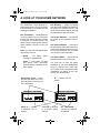
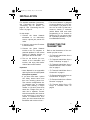
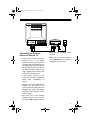
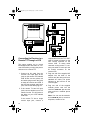
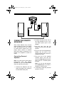
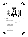
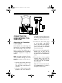
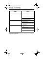
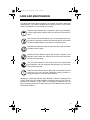
working.fm Page 1 Tuesday, July 13, 1999 12:39 PM
Cat. No. 15-1975
OWNER’S MANUAL
Please read before using this equipment.
Audio/Video
Home Network
working.fm Page 2 Tuesday, July 13, 1999 12:39 PM
INTRODUCTION
Your RCA Audio/Video Home Network delivers clear stereo sound and
sharp color video images up to 500
feet away from the A/V source. Because it transmits at a low frequency
(30 MHz), your Home Network can
share the same phone lines as voice
and data signals, so you can still use
your phone, fax, or modem while you
enjoy broadcast, recorded, or satellite
programming on a TV anywhere in
your home!
Just connect the Home Network’s
transmitter to AC power, a phone line,
and an audio or video source, and its
receiver to AC power, a phone line,
and a remote TV, audio receiver, or
powered speakers. When you turn on
the components you connected, the
transmitter sends the signals from the
source to the receiver, so you can:
• watch VCR or DVD movies on
any TV in your home without running costly cable, moving your
VCR, or buying another one
• watch cable or satellite programming on any TV in your home
• listen to stereo music on powered
speakers inside or outside your
home
• receive computer images and
sound on a remote TV (additional
equipment required)
• monitor your sleeping baby, playing children, or sick family members, or see who is outside your
door on your TV using a camcorder or miniature security camera
With additional equipment (not supplied), you can even use the Home
Network to show presentations from a
desktop or laptop computer on a TV
screen or view TV programming on a
computer’s monitor.
Your Home Network comes with an
infrared (IR) remote control emitter
that allows you to use an audio or video source’s remote control to control
the device from another room, even if
the device is not within line-of-sight of
the Home Network transmitter.
Note: This equipment complies with
the limits for a Class A digital device
as specified in Part 15 of FCC Rules.
These limits provide reasonable protection against radio and TV interference as long as you use the
equipment in a commercial area. The
equipment produces radio frequency
energy and can cause radio and TV
interference. If you use the equipment
in a residential area, you must correct
any interference problem at your own
expense.
© 1999 Tandy Corporation.
All Rights Reserved.
RadioShack is a registered trademark used by Tandy Corporation.
2
working.fm Page 3 Tuesday, July 13, 1999 12:39 PM
We have designed your Home Network to conform to federal regulations, and you can connect it to most
telephone lines. However, each device (such as a telephone or answering machine) that you connect to the
telephone line draws power from the
telephone line. We refer to this power
draw as the device’s ringer equivalence number, or REN. The REN is
on the bottom of your transmitter and
receiver.
If you use more than one phone or
other device on the line, add up all of
the RENs. If the total is more than five
(or three in rural areas), your telephones might not ring. If ringer operation is
impaired, remove a device from the
line.
Your Home Network complies with
Part 68 of FCC Rules. You must,
upon
request, provide the FCC registration
number and the REN to your telephone company. Both numbers are
on the bottom of the transmitter and
receiver.
Note: You must not connect your
Home Network to:
• coin-operated systems
Your Home Network is ETL listed to
UL standards and meets all applicable FCC standards.
WARNING:
To reduce the risk of fire or
shock hazard, do not expose this product to
rain or moisture.
CAUTION
RISK OF ELECTRIC
SHOCK. DO NOT OPEN.
!
CAUTION: TO REDUCE THE RISK
OF ELECTRIC SHOCK, DO NOT
REMOVE COVER OR BACK. NO USERSERVICEABLE PARTS INSIDE. REFER
SERVICING TO QUALIFIED PERSONNEL.
This symbol is intended to alert
you to the presence of uninsulated dangerous voltage within
the product’s enclosure that
might be of sufficient magnitude
to constitute a risk of electric
shock. Do not open the product’s case.
!
This symbol is intended to inform you that important operating
and
maintenance
instructions are included in the
literature accompanying this
product.
For residential use only. Manufactured and sold under license from Inline Connection Corporation.
• party-line systems
• most electronic key telephone
systems
• PBXs
3
working.fm Page 4 Tuesday, July 13, 1999 12:39 PM
A LOOK AT YOUR HOME NETWORK
The Audio/Video Home Network includes these items. Be sure you have
them all before you discard the box
and begin installation.
One Transmitter — sends audio/video (A/V) signals from an A/V source
through the Home Network receiver
to a remote TV or audio receiver, and
relays remote control signals from the
Home Network receiver to the A/V
source
Note: You can send A/V signals from
any of these sources:
• Audio — CD player, stereo
receiver or cassette deck
• Video — VCR, cable TV, laser
disc player, DVD, camcorder,
security camera, computer or satellite system
Audio/Video Jacks — stereo
left and right jacks and a single video jack to connect your
A/V components
PHONE
IN
LINE
OUT
One Receiver — relays A/V signals
from the Home Network transmitter to
the remote TV or audio receiver, and
sends remote control signals through
the transmitter to the A/V source
Two Power Adapters — provide 15V
DC power to the transmitter and receiver
One Infrared Emitter — connects to
the transmitter and sends infrared remote control signals from the receiver
to A/V sources which are not within
“line-of-sight” of the transmitter
Two Phone Wires — connect Home
Network units to your phone jacks
You need one or more AV cables
(available at your local RadioShack
store) to connect your Home Network. Refer to the instructions under
“Installation” on page 5 for the connection you need to make.
IR — connect the IR
emitter
OUT
DC15V
300mA
Left – AUDIO – Right
Phone In — connect
a telephone, fax, or
modem
4
LINE
OUT
DC15V
300mA
IN
OUT
VIDEO
PHONE
IN
IR
VIDEO
Line Out — connect
to a modular phone
line jack
Left – AUDIO – Right
DC 15V 300mA —
connect the supplied
AC adapter
working.fm Page 5 Tuesday, July 13, 1999 12:39 PM
INSTALLATION
For detailed installation instructions,
see “Connecting the Transmitter,”
“Connecting the IR Emitter” on
page 10, and “Connecting the Receiver” on page 10.
It’s this simple:
1. Connect the Home Network
transmitter to an audio/video
source, a phone jack, and an AC
outlet.
2. If desired, connect the IR emitter
to the transmitter.
3. Connect the Home Network
receiver to the TV, computer, or
powered speakers in the remote
viewing or listening location, a
phone jack and an AC outlet.
4. Turn on the devices you connected to the transmitter and
receiver, and enjoy clear audio/
video at the remote location!
Important:
• Home Network is not compatible
with Key Service Unit (KSU) multiline phone systems.
• If you have more than 1 phone
line: Many homes have more
than one incoming phone line.
Two common configurations are:
(1) separate lines on separate
jacks, each bearing a unique
number, or (2) two to three lines
wired into a single RJ11 jack. If
each line is separate, connect
both the transmitter and receiver
to the same line. If you have a
mixture of standard and RJ11
jacks, you must connect both the
transmitter and receiver to line 1.
• The Home Network is designed
to connect directly to a TV’s linelevel outputs. If you want to connect it to an older TV that has a
screw-on, coaxial “F” connector
(which allows VCR and cable
programming to be viewed on
channel 3 or 4), you need a video
RF modulator (available at your
local RadioShack store).
CONNECTING THE
TRANSMITTER
Refer to the illustrations of the connection you plan to use :
• “To Transmit Audio/Video from a
VCR” on page 7
• “To Transmit Audio/Video from a
Cable TV Hookup” on page 7
• “To Transmit Audio/Video from a
Satellite Receiver, DVD, or Laserdisc” on page 8
• “To Transmit Audio/Video from a
Camcorder” on page 8
• “To Transmit Audio/Video from an
A/V Receiver” on page 9
• “To Transmit Audio from a Stereo
Receiver” on page 9
• “To Transmit Audio from a CD
Player or Cassette Deck” on
page 9
5
working.fm Page 6 Tuesday, July 13, 1999 12:39 PM
1. Connect an A/V cable from the
transmitter’s A/V jacks to the A/V
jacks on the back of your audio/
video source labeled LINE OUT,
A/V, or A/V OUT. Be sure the yellow, red and white plugs match
the yellow, red and white jacks on
both the audio/video source and
the transmitter.
Notes:
• If your VCR or cable converter box has only one output
for audio (mono sound only),
connect the white plug to that
single audio output and to the
transmitter’s AUDIO LEFT jack.
• If your A/V source (VCR, satellite receiver, DVD, or laserdisc
player) has only one set of A/V
output jacks and you want to
use it with a nearby TV, connect a coaxial cable (available
at your local RadioShack
store) from the OUT port on
your A/V source to the VHF/
UHF IN port on your TV. To
view cable transmissions on
that TV, connect your incoming
cable TV source to the IN port
on your A/V source.
• With some camcorders, you
might need to use the camcorder’s
supplied
adapter
patch cord.
• You can connect the Home
Network
to
your
stereo
receiver to enjoy sound from a
CD player, cassette deck, or
radio. If you do this, you must
also connect either powered
speakers or another amplifier
6
to the Home Network receiver
at the remote site (see “Connecting Remote Speakers” on
page 13).
• The yellow video plug is not
used with audio components
such as CD players, stereo
receivers or cassette decks.
• To transmit audio/video from a
component connected to an A/
V receiver, select that component to be the A/V receiver’s
output. Refer to your A/V
receiver’s manual for instructions.
2. Plug one end of the
modular phone cord
transmitter’s LINE OUT
the other end into a
phone line jack.
supplied
into the
jack and
modular
Note: You can use the transmitter’s PHONE IN jack to connect a
telephone, modem or fax.
3. Plug one end of the supplied AC
adapter into the back of the transmitter and the other end into a
standard AC outlet. The power
indicator on the face of the transmitter lights.
Note: The other light-emitting
diodes (LEDs) on the transmitter’s face transmit infrared (IR)
signals to A/V source components. They never light.
working.fm Page 7 Tuesday, July 13, 1999 12:39 PM
To Transmit Audio/Video from a VCR
OUT
PHONE
IN
LINE
OUT
IN
DC15V
300mA
VIDEO
OUT
VIDEO
VCR1
IN
IR
VCR 1
AUDIO
Left – AUDIO – Right
LEFT
RIGHT
IN
IN
IN
OUT
OUT
OUT
To Transmit Audio/Video from a Cable TV Hookup
VIDEO
CABLE/ANT.
AUDIO
LEFT
RIGHT
IN
LINE OUT
CABLE/ANT.
OUT
CABLE/ANT. IN
VIDEO IN
AUDIO IN
OUT
LEFT
RIGHT
PHONE
IN
LINE
OUT
DC15V
300mA
IN
IR
VIDEO
Left – AUDIO – Right
7
working.fm Page 8 Tuesday, July 13, 1999 12:39 PM
To Transmit Audio/Video from a Satellite Receiver, DVD, or
Laserdisc
VIDEO
CABLE/ANT.
IN
AUDIO
LEFT
RIGHT
SATILLITE
LINE OUT 1
IN
CABLE/ANT.
OUT
CABLE/ANT. IN
VIDEO IN
LINE OUT 2
AUDIO IN
LEFT
RIGHT
OUT
PHONE
IN
IN
IR
VIDEO
Left – AUDIO – Right
To Transmit Audio/Video from a Camcorder
OUT
PHONE
IN
LINE
OUT
DC15V
300mA
IN
IR
VIDEO
Left – AUDIO – Right
VIDEO
LINE OUT
8
AUDIO
LINE
OUT
DC15V
300mA
working.fm Page 9 Tuesday, July 13, 1999 12:39 PM
To Transmit Audio/Video from an A/V Receiver
VIDEO
CABLE/ANT.
IN
AUDIO
LEFT
RIGHT
LINE IN
CABLE/ANT.
OUT
CABLE/ANT. IN
VIDEO IN
LINE OUT
AUDIO IN
LEFT
RIGHT
OUT
PHONE
IN
LINE
OUT
DC15V
300mA
IN
IR
VIDEO
Left – AUDIO – Right
To Transmit Audio from a Stereo Receiver
AUDIO
LEFT
OUT
PHONE
IN
LINE
OUT
RIGHT
LINE IN
DC15V
300mA
IN
IR
VIDEO
LINE OUT
Left – AUDIO – Right
To Transmit Audio from a CD Player or Cassette Deck
OUT
IN
IR
VIDEO
PHONE
IN
LINE
OUT
DC15V
300mA
AUDIO
LEFT
RIGHT
LINE OUT
Left – AUDIO – Right
9
working.fm Page 10 Tuesday, July 13, 1999 12:39 PM
CONNECTING THE IR
EMITTER
Your Home Network also allows you
to control the A/V source using an existing remote control. The Home Network receiver sends your remote
control’s IR signal through the phone
line to the Home Network transmitter,
which converts the signal back to the
original IR signal and beams it to the
audio/video source.
If you want to use an A/V source’s remote control to control a source
which is not within “line-of-sight” of
the Home Network transmitter, follow
these steps to connect the Home Network IR emitter.
1. Plug the IR emitter into the IR jack
on the back of the transmitter (to
the left of the yellow video jack).
2. Locate the IR sensor on the
source you want to control.
If the sensor is not clearly
labeled, consult the owner’s manual for that component, try pointing the remote control at different
areas on the front of the component from less than 1 inch away
and pressing ON or OFF. When
the component turns on or off,
you have found the approximate
location of the IR sensor.
3. Position the IR emitter so that it is
within “line-of-sight” of the IR sensors on the A/V sources you want
to control. Cut a piece of the supplied hook-and-loop tape to
secure the emitter In this position.
10
4. At the remote location, position
the receiver so the remote control
signal can strike the IR window
on the bottom front of the
receiver.
To use the remote control, point it
at the front of the receiver and
press the desired buttons.
CONNECTING THE
RECEIVER
To receive A/V signals on a remote
TV where you will watch the programming from your audio/video source,
you can:
• connect the Home Network
receiver directly to the remote TV
• connect the Home Network
receiver to the TV through a VCR
(so you can record the transmitted audio and video)
Notes:
• The signal indicator
receiver’s right face
show that A/V signals
transmitter are being
through the phone line.
on the
lights to
from the
received
• If the remote TV has picture-inpicture (PIP) capabilities, you can
view any image transmitted by
Home Network, such as your
sleeping baby, in a small inset
picture while enjoying other programming on the rest of the
screen. Consult your TV’s manual for instructions.
working.fm Page 11 Tuesday, July 13, 1999 12:39 PM
CABLE/ANT. IN
VIDEO IN
AUDIO IN
PHONE
IN
LEFT
RIGHT
Connecting the Receiver
Direct to a Remote TV
1. If the remote TV has A/V jacks,
connect a set of A/V cables
between the TV’s and receiver’s
A/V jacks. Be sure the yellow, red
and white plugs match the yellow,
red and white jacks on both the
TV and the receiver. If the TV has
only a single jack for audio input,
connect the white plug to it.
LINE
OUT
DC15V
300mA
OUT
VIDEO
Left – AUDIO – Right
other end into a modular phone
line jack.
Note: You can use the transmitter’s PHONE IN jack to connect a
telephone, modem or fax.
If the remote TV has no A/V
jacks, see the third “Important”
bullet under “Installation” on
page 5.
2. Plug one end of the supplied AC
adapter into the back of the
receiver and the other end into a
standard AC outlet. The power
indicator on the left face of the
receiver lights.
3. Plug one end of the supplied
modular phone cord into the
receiver’s LINE OUT jack and the
11
working.fm Page 12 Tuesday, July 13, 1999 12:39 PM
VIDEO
CABLE/ANT.
IN
AUDIO
LEFT
RIGHT
LINE IN
CABLE/ANT.
OUT
CABLE/ANT. IN
VIDEO IN
LINE OUT
AUDIO IN
LEFT
RIGHT
PHONE
IN
LINE
OUT
DC15V
300mA
OUT
VIDEO
Connecting the Receiver to a
Remote TV Through a VCR
This setup enables you to record
transmitted audio and video on a remote VCR while you enjoy the picture
and sound on a remote TV.
1. Connect an AV cable from the
receiver’s A/V input jacks to the
jacks on the remote VCR labeled
LINE IN. Be sure the yellow, red
and white plugs match the jacks
on both the receiver and VCR. If
the VCR has a single audio input
jack, connect the white plug to it.
2. If the remote TV has A/V input
jacks, connect another set of A/V
cables from the TV’s A/V jacks to
the jacks on your VCR labeled
LINE OUT.
If the remote TV has a single
coaxial input port, connect a
12
Left – AUDIO – Right
coaxial cable from the TV’s VHF/
UHF IN coaxial connector to the
OUT coaxial connector on the
remote VCR. To watch cable
channels on the remote TV, connect your cable TV hook-up to the
IN coaxial connector on the
remote VCR.
3. Plug one end of the supplied AC
adapter into the back of the
receiver and the other end into a
standard AC outlet. The power
indicator on the left face of the
receiver lights.
4. Plug one end of the supplied
modular phone cord into the
receiver’s LINE OUT jack and the
other end into a modular phone
line jack.
Note: You can use the transmitter’s PHONE IN jack to connect a
telephone, modem or fax.
working.fm Page 13 Tuesday, July 13, 1999 12:39 PM
PHONE
IN
LINE
OUT
DC15V
300mA
OUT
VIDEO
Left – AUDIO – Right
CONNECTING REMOTE
SPEAKERS
Since Home Network only receives
stereo signals and does not amplify
them, the speakers you use to listen
to remote stereo sound from a CD
player, stereo receiver or cassette
deck must either be powered or attached to an amplifier or stereo receiver.
Connecting Powered
Speakers
Note: You need a mini stereo phono
jack-to-stereo RCA plug adapter
(available at your local RadioShack
store) to make this connection.
1. Connect the adapter’s red and
white A/V plugs to the receiver’s
red and white audio jacks.
2. Connect the plug at the end of
the right speaker’s wire to the
mini stereo phono jack on the
adapter.
3. Plug the wire from the left
speaker into the back of the right
speaker.
4. Plug one end of the supplied AC
adapter into the back of the
receiver and the other end into a
standard AC outlet.
5. Plug one end of the supplied
modular phone cord into the
receiver’s LINE OUT jack and the
other end into a modular phone
line jack.
Note: You can use the transmitter’s PHONE IN jack to connect a
telephone, modem or fax.
6. If necessary, adjust the powered
speakers’ volume.
13
working.fm Page 14 Tuesday, July 13, 1999 12:39 PM
PHONE
IN
LINE
OUT
DC15V
300mA
OUT
VIDEO
PHONO
AUDIO
LEFT
RIGHT
TAPE/VCR/DAT
AUDIO
LEFT
Left – AUDIO – Right
LEFT
RIGHT
SPEAKER SPEAKER
RIGHT
LINE IN
LINE OUT
Connecting Nonpowered
Speakers
You can listen to remote stereo
sound without using powered speakers as long as you use an amplifier or
stereo receiver with a volume control
to boost the signal from the Home
Network receiver.
1. Connect the red and white plugs
on an A/V cable from the red and
white audio jacks on the Home
Network receiver to the IN 1 or IN
2 jacks on your stereo receiver or
amplifier. Be sure the red and
white plugs match the red and
white jacks on both the Home
Network receiver and the stereo
receiver or amplifier. (The yellow
video plug is not used.)
2. Run speaker wire from your stereo receiver or amplifier to your
speakers.
14
3. Plug one end of the supplied AC
adapter into the back of the
receiver and the other end into a
standard AC outlet.
4. Plug one end of the supplied
modular phone cord into the
receiver’s LINE OUT jack and the
other end into a modular phone
line jack.
Note: You can use the transmitter’s PHONE IN jack to connect a
telephone, modem or fax.
working.fm Page 15 Tuesday, July 13, 1999 12:39 PM
PHONE
IN
LINE
OUT
DC15V
300mA
OUT
VIDEO
Left – AUDIO – Right
CONNECTING THE
HOME NETWORK TO A
COMPUTER
converter) from the VGA port on
the back of your computer’s CPU
to the VGA IN plug on the converter.
Connecting the Transmitter
to a Computer
3. Connect the yellow video plugs
on an A/V cable to the VIDEO
jack on the back of the VGA-toTV converter and the VIDEO IN
jack on the back of the Home
Network transmitter.
Home Network can send images and
sounds from a computer equipped
with a sound card to any TV in the
home or office. This allows you to
send presentations from your desktop
or laptop computer to a large TV
screen.
Note: You need a VGA-to-TV converter (available through your local
RadioShack store) to make this connection.
1. Connect the monitor cable from
your computer’s monitor to the
VGA OUT plug on the VGA-to-TV
converter.
4. Plug one end of the supplied AC
adapter into the back of the
Home Network transmitter and
the other end into a standard AC
outlet.
5. Plug one end of the
modular phone cord
transmitter’s LINE OUT
the other end into a
phone line jack.
supplied
into the
jack and
modular
Note: You can use the transmitter’s PHONE IN jack to connect a
telephone, modem or fax.
2. Connect a VGA extension cable
(supplied with the VGA-to-TV
15
working.fm Page 16 Tuesday, July 13, 1999 12:39 PM
TROUBLESHOOTING
Problem
No picture or sound
Solution
Make sure power on the remote TV and video
source (VCR, DVD, satellite, etc.) is on.
Make sure power plugs are pushed in all the
way.
Check all cable connections.
Make sure the transmitter and receiver are
connected to the same phone line.
Remote control does not work
Remove any obstructions between the transmitter and the A/V source.
Make sure the IR emitter is connected and
pointing toward the sensor on the A/V source
you want to control.
Sound but no picture
Make sure A/V inputs and outputs are not
reversed.
Connect the AC adapter.
Connect the yellow A/V plug.
Make sure Home Network is receiving a video
signal.
If your Home Network is not operating as it should, take it to your local RadioShack store for assistance.
16
working.fm Page 17 Tuesday, July 13, 1999 12:39 PM
CARE AND MAINTENANCE
Your RCA Audio/Video Home Network is an example of superior design and
craftsmanship. The following suggestions will help you care for your Audio/
Video Home Network so you can enjoy it for years.
Keep the Home Network dry. If it gets wet, wipe it dry immediately.
Liquids might contain minerals that can corrode the electronic circuits.
Use and store the Home Network only in normal temperature environments. Temperature extremes can shorten the life of electronic
devices, damage batteries, and distort or melt plastic parts.
Keep the Home Network away from dust and dirt, which can cause
premature wear of parts.
Handle the Home Network gently and carefully. Dropping it can
damage circuit boards and cases and can cause the Home Network to work improperly.
Use only fresh batteries of the required size and recommended
type. Batteries can leak chemicals that damage your Home Network’s electronic parts.
Wipe the Home Network with a damp cloth occasionally to keep it
looking new. Do not use harsh chemicals, cleaning solvents, or
strong detergents to clean the Home Network.
Modifying or tampering with the Home Network’s internal components can
cause a malfunction and might invalidate its warranty and void your FCC authorization to operate it. If the trouble is affecting the telephone lines, the
phone company can ask you to disconnect your Home Network until you have
resolved the problem.
17
working.fm Page 18 Tuesday, July 13, 1999 12:39 PM
THE FCC WANTS YOU
TO KNOW
In the unlikely event that your phone
causes problems on the phone line,
the phone company can temporarily
discontinue your service. If this happens, the phone company attempts to
notify you in advance. If advance notice is not practical, the phone company notifies you as soon as possible
and advises you of your right to file a
complaint with the FCC.
Also, the phone company can make
changes to its lines, equipment, operations, or procedures that could affect
the operation of this telephone. The
telephone company notifies you of
these changes in advance, so you
can take the necessary steps to prevent interruption of your telephone
service.
18
LIGHTNING
Your telephone has built-in protection
circuits to reduce the risk of damage
from surges in telephone line and
power line current. These protection
circuits meet or exceed the FCC requirements. However, lightning striking the telephone or power lines can
damage your telephone.
Lightning damage is not common.
Nevertheless, if you live in an area
that has severe electrical storms, we
suggest that you unplug your phone
during storms to reduce the possibility
of damage.
working.fm Page 19 Tuesday, July 13, 1999 12:39 PM
SPECIFICATIONS
Power Supply:
Input ................................................................................ 120 VAC, 60 Hz, 11 W
Output .................................................. 15V DC, 300 mA (Class 2 Transformer)
Dimensions (HWD) ........................................................ 2.33 x 6.5 x 5.5 Inches
Weight:
Component ............................................................................................. 13.7 oz
Entire Contents of Package ..................................................................... 3.9 lbs
Operating Environment:
Temperature .................................................................. 50 to 95°F (10 to 35°C)
Relative Humidity ............................................................................... 15 to 70%
FCC Registration Number .............................................. 5MXUSA-32947-OT-N
Ringer Equivalence .................................................................................... 1.3 B
Specifications are typical; individual units might vary. Specifications are subject
to change and improvement without notice.
19
working.fm Page 20 Tuesday, July 13, 1999 12:39 PM
Limited Ninety-Day Warranty
This product is warranted by RadioShack against manufacturing defects in material and workmanship under normal use for ninety (90) days from the date of purchase from RadioShack companyowned stores and authorized RadioShack franchisees and dealers. EXCEPT AS PROVIDED
HEREIN, RadioShack MAKES NO EXPRESS WARRANTIES AND ANY IMPLIED WARRANTIES,
INCLUDING THOSE OF MERCHANTABILITY AND FITNESS FOR A PARTICULAR PURPOSE,
ARE LIMITED IN DURATION TO THE DURATION OF THE WRITTEN LIMITED WARRANTIES
CONTAINED HEREIN. EXCEPT AS PROVIDED HEREIN, RadioShack SHALL HAVE NO LIABILITY OR RESPONSIBILITY TO CUSTOMER OR ANY OTHER PERSON OR ENTITY WITH RESPECT TO ANY LIABILITY, LOSS OR DAMAGE CAUSED DIRECTLY OR INDIRECTLY BY USE
OR PERFORMANCE OF THE PRODUCT OR ARISING OUT OF ANY BREACH OF THIS WARRANTY, INCLUDING, BUT NOT LIMITED TO, ANY DAMAGES RESULTING FROM INCONVENIENCE, LOSS OF TIME, DATA, PROPERTY, REVENUE, OR PROFIT OR ANY INDIRECT,
SPECIAL, INCIDENTAL, OR CONSEQUENTIAL DAMAGES, EVEN IF RadioShack HAS BEEN ADVISED OF THE POSSIBILITY OF SUCH DAMAGES.
Some states do not allow the limitations on how long an implied warranty lasts or the exclusion of incidental or consequential damages, so the above limitations or exclusions may not apply to you.
In the event of a product defect during the warranty period, take the product and the RadioShack
sales receipt as proof of purchase date to any RadioShack store. RadioShack will, at its option, unless otherwise provided by law: (a) correct the defect by product repair without charge for parts and
labor; (b) replace the product with one of the same or similar design; or (c) refund the purchase
price. All replaced parts and products, and products on which a refund is made, become the property of RadioShack. New or reconditioned parts and products may be used in the performance of
warranty service. Repaired or replaced parts and products are warranted for the remainder of the
original warranty period. You will be charged for repair or replacement of the product made after the
expiration of the warranty period.
This warranty does not cover: (a) damage or failure caused by or attributable to acts of God, abuse,
accident, misuse, improper or abnormal usage, failure to follow instructions, improper installation or
maintenance, alteration, lightning or other incidence of excess voltage or current; (b) any repairs
other than those provided by a RadioShack Authorized Service Facility; (c) consumables such as
fuses or batteries; (d) cosmetic damage; (e) transportation, shipping or insurance costs; or (f) costs
of product removal, installation, set-up service adjustment or reinstallation.
This warranty gives you specific legal rights, and you may also have other rights which vary from
state to state.
RadioShack Customer Relations, 200 Taylor Street, 6th Floor, Fort Worth, TX 76102
We Service What We Sell
04/99
RadioShack
A Division of Tandy Corporation
Fort Worth, Texas 76102
07A99
Printed in China