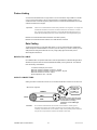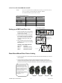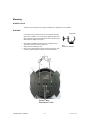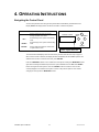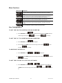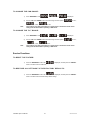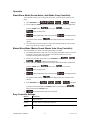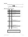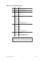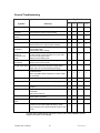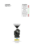
1
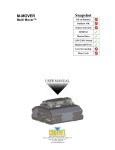
Snapshot
DMX-685
Intimidator Spot 2.0™
Ok on Dimmer
Outdoor OK
Sound Activated
DMX512
Master/Slave
115V/230V Switch
Replaceable Fuse
User Serviceable
Duty Cycle
USER MANUAL
Chauvet, 3000 N 29th Ct, Hollywood, FL 33020 U.S.A.
(800) 762-1084 – (954) 929-1115
FAX (954) 929-5560
www.chauvetlighting.com
TABLE OF CONTENTS
1. BEFORE YOU BEGIN....................................................................................................................................................... 3
WHAT IS INCLUDED .............................................................................................................................................................. 3
UNPACKING INSTRUCTIONS .................................................................................................................................................. 3
AC POWER ......................................................................................................................................................................... 3
CONTACT US ...................................................................................................................................................................... 3
SAFETY INSTRUCTIONS ........................................................................................................................................................ 4
2. INTRODUCTION ............................................................................................................................................................... 5
FEATURES .......................................................................................................................................................................... 5
DMX CHANNEL SUMMARY ................................................................................................................................................... 5
PRODUCT OVERVIEW .......................................................................................................................................................... 6
3. SETUP ............................................................................................................................................................................... 7
LAMP .................................................................................................................................................................................. 7
Lamp Replacement....................................................................................................................................................... 7
Lamp Alignment How-To .............................................................................................................................................. 8
FUSE REPLACEMENT ........................................................................................................................................................... 8
REPLACING GOBOS ............................................................................................................................................................. 9
FIXTURE LINKING ............................................................................................................................................................... 10
Data Cabling ............................................................................................................................................................... 10
DMX Data Cable.................................................................................................................................................. 10
Cable Connectors ................................................................................................................................................ 10
3-Pin to 5-Pin Conversion Chart .......................................................................................................................... 11
SETTING UP A DMX SERIAL DATA LINK .............................................................................................................................. 11
STAND-ALONE/MASTER/SLAVE FIXTURE LINKING ............................................................................................................... 11
MOUNTING ........................................................................................................................................................................ 12
Orientation ........................................................................................................................................................... 12
Rigging................................................................................................................................................................. 12
4. OPERATING INSTRUCTIONS........................................................................................................................................ 13
NAVIGATING THE CONTROL PANEL ..................................................................................................................................... 13
MENU MAP........................................................................................................................................................................ 14
Menu Functions .......................................................................................................................................................... 15
User Configurations .................................................................................................................................................... 15
To set the pan to inverting or non-inverting: ........................................................................................................ 15
To set the tilt to inverting or non-inverting: .......................................................................................................... 15
To reverse the display: ........................................................................................................................................ 15
To set the fixture to 16-bit or 8-bit mode:............................................................................................................. 15
To change the pan range: ................................................................................................................................... 16
To change the tilt range: ...................................................................................................................................... 16
Service Functions ....................................................................................................................................................... 16
To reset the fixture:.............................................................................................................................................. 16
To restore all settings to their factory defaults: .................................................................................................... 16
OPERATION ....................................................................................................................................................................... 17
Stand-Alone Mode (Sound-Active, Auto Mode, Easy Controller): .............................................................................. 17
Master/Slave Mode (Master Sound, Master Auto, Easy Controller): .......................................................................... 17
Easy Controller Settings ............................................................................................................................................. 17
DMX Mode .................................................................................................................................................................. 18
DMX Channel Values (16-bit mode) ........................................................................................................................... 18
DMX Channel Values (8-bit mode) ............................................................................................................................. 19
GENERAL TROUBLESHOOTING ........................................................................................................................................... 20
TECHNICAL SUPPORT ........................................................................................................................................................ 21
5. APPENDIX....................................................................................................................................................................... 21
DMX PRIMER .................................................................................................................................................................... 21
GENERAL MAINTENANCE ................................................................................................................................................... 21
RETURNS PROCEDURE ...................................................................................................................................................... 22
CLAIMS ............................................................................................................................................................................. 22
TECHNICAL SPECIFICATIONS .............................................................................................................................................. 23
Intimidator Spot 2.0 User Manual
2
2007-01-29/10:32
1. BEFORE YOU BEGIN
What is included
¾
¾
¾
¾
¾
1 x Intimidator Spot 2.0™
250W EHJ Lamp
Power Cord
Warranty Card
User Manual
Unpacking Instructions
Immediately upon receiving a fixture, carefully unpack the carton, check the contents to ensure that
all parts are present, and have been received in good condition. Notify the shipper immediately and
retain packing material for inspection if any parts appear damaged from shipping or the carton itself
shows signs of mishandling. Save the carton and all packing materials. In the event that a fixture
must be returned to the factory, it is important that the fixture be returned in the original factory box
and packing.
AC Power
To determine the power requirements for a particular fixture, see the label affixed to the back plate of
the fixture or refer to the fixture’s specifications chart. A fixture’s listed current rating is its average
current draw under normal conditions. All fixtures must be powered directly off a switched circuit and
cannot be run off a rheostat (variable resistor) or dimmer circuit, even if the rheostat or dimmer
channel is used solely for a 0% to 100% switch. Before applying power to a
Figure 1 - AC Voltage Switch
fixture, check that the source voltage matches the fixture’s requirement.
Check the fixture or device carefully to make sure that if a voltage selection
switch exists that it is set to the correct line voltage you will use.
Warning!
Verify that the voltage select switch on your unit matches the
line voltage applied. Damage to your fixture may result if the
line voltage applied does not match the voltage indicated on
the voltage selector switch. All fixtures must be connected to
circuits with a suitable Earth Ground.
Not all fixtures have a voltage
select switch. Please be sure to
connect to the proper voltage.
Contact Us
World Wide
General Information
Chauvet Lighting
th
3000 North 29 Court
Hollywood, FL 33020
voice: 954.929.1115
fax:
954.929.5560
toll free: 800.762.1084
Technical Support
Chauvet Lighting
th
3000 North 29 Court
Hollywood, FL 33020
voice: 954.929.1115 (Press 4)
fax:
954.929.5560 (Attention: Service)
World Wide Web
www.chauvetlighting.com
Intimidator Spot 2.0 User Manual
3
2007-01-29/10:32
Safety Instructions
Please read these instructions carefully, which includes important
information about the installation, usage and maintenance of this
product.
•
•
•
•
•
•
•
•
•
•
•
•
•
Caution!
Please keep this User Guide for future consultation. If you sell the unit to another user, be sure that
they also receive this instruction booklet.
Always make sure that you are connecting to the proper voltage, and that the line voltage you are
connecting to is not higher than that stated on the decal or rear panel of the fixture.
This product is intended for indoor use only!
To prevent risk of fire or shock, do not expose fixture to rain or moisture. Make sure there are no
flammable materials close to the unit while operating.
The unit must be installed in a location with adequate ventilation, at least 20in (50cm) from adjacent
surfaces. Be sure that no ventilation slots are blocked.
Always disconnect from power source before servicing or replacing lamp or fuse and be sure to
replace with same lamp source.
Secure fixture to fastening device using a safety chain. Never carry the fixture solely by its head. Use
its carrying handles.
Maximum ambient temperature (Ta) is 104°F (40°C). Do not operate fixture at temperatures higher
than this.
In the event of a serious operating problem, stop using the unit immediately. Never try to repair the
unit by yourself. Repairs carried out by unskilled people can lead to damage or malfunction. Please
contact the nearest authorized technical assistance center. Always use the same type spare parts.
Don’t connect the device to a dimmer pack.
Make sure the power cord is never crimped or damaged.
Never disconnect the power cord by pulling or tugging on the cord.
Avoid direct eye exposure to the light source while it is on.
There are no user serviceable parts inside the unit. Do not open the housing or
attempt any repairs yourself. In the unlikely event your unit may require service,
please contact CHAUVET at: 954-929-1115.
Intimidator Spot 2.0 User Manual
4
2007-01-29/10:32
2. INTRODUCTION
Features
•
•
•
•
6 to 8-channel DMX-512 moving yoke
Pan: 540o / tilt: 270o
Variable strobe/shutter
Color wheel:
7 colors + white
Rainbow color spin effect
• Rotating gobo wheel:
7 interchangeable, rotating gobos + open
5 metal, 2 dichroic gobos
Gobo wheel spin effect
• Variable motorized dimmer (0 – 100%)
Ad d i t i o n a l F e a t u r e s
• Gobo size: 23.5mm outside, 17.5mm image, 0.2mm max thickness
• Round base design for flush mounting
• User-selectable pan/tilt ranges
Pan: 540°, 360°, 180°
Tilt: 270°, 180°, 90°
• Built-in automatic programs via master/slave
• Built-in sound activated programs via master/slave
• User-selectable 16bit or 8bit pan/tilt resolution
• Compact and lightweight
• Electronic transformer
• LED display menu with invert
• Display auto on/off
• Pan/tilt invert option
• Thermal switch
• Fan cooled
Optional Controllers
•
CA-9 Easy Controller
DMX Channel Summary
CHANNEL FUNCTION (16-BIT MODE)
CHANNEL
FUNCTION (8-BIT MODE)
1
Pan
1
Pan
2
Pan Fine
2
Tilt
3
Tilt
3
Shutter
4
Tilt Fine
4
Color
5
Shutter
5
Gobo
6
Color
6
Gobo Rotation
7
Gobo
8
Gobo Rotation
Intimidator Spot 2.0 User Manual
5
2007-01-29/10:32
Product Overview
Head
Focusing
Lens
Yoke
Control
Panel
Base
Rear of Base
Easy
Controller
Connector
AC Power Input
& Fuse Holder
DMX Input
Connector
DMX Output
Connector
Voltage
Selector
Switch
Intimidator Spot 2.0 User Manual
6
2007-01-29/10:32
3. SETUP
Lamp
You will need to install a lamp prior to the initial operation of the fixture. A 250W EHJ lamp is
included.
Warning!
When replacing the lamp, please wait 15 minutes after powering down to allow the
unit to cool down! Always disconnect from main power prior to lamp replacement.
Do not touch the envelope (glass area) of the bulb with bare hands. If this happens, clean the lamp
with alcohol and wipe it with a lint free cloth before installation.
Lamp Replacement
1)
Lamp Access Screws
Remove the four screws indicated in
Figure A to access the lamp.
2)
Hold the lamp with a lint-free cloth,
Figure A
and pull the lamp directly out of the
socket as shown in Figure B.
3)
Hold the new lamp with a lint-free
cloth, and insert directly into the
socket.
4)
Reinsert the lamp housing into the
fixture, and tighten the four screws
removed in step 1.
Note:
The lamp may need to be aligned. If
so, follow the lamp alignment
Figure B
procedures on the following page.
Intimidator Spot 2.0 User Manual
7
2007-01-29/10:32
Lamp Alignment How-To
Often, after a new installation of a lamp, you will find that there is an uneven field of light or what is
refered to as a hot spot. This is due to the most intense point of the lamp source not being positioned
optimally within the reflector.
Lamp alignment screws
There are three lamp alignment screws provided at the base of
the fixture. Turning these screws allow you to optimize the
projection quality of the spot as well as the overall intensity of the
beam.
1)
Project a white spot against any flat surface. Preferably the
surface should be white or pastel in color.
2)
Turning the lamp alignment screws, try to position the hot spot in the center of the beam as best
as possible. This could require many attempts on your part. It is advisable to even out the
screws prior to lamp alignment as described in the illustration.
3)
Once the hot spot is in the center of the spot, do your best to turn all screws equally as to affect
movement up or down within the reflector.
4)
As you move in and out of optimum lamp focus, you will see the hot spot either get wider or
narrower. The goal is to either totally diminish the hot spot by having it widen and spread across
the entire spot or moving the hot spot so that it covers as much of the beam spot area as
possible.
Disconnect the power cord before replacing a fuse and always
replace with the same type fuse.
Fuse Replacement
With a flat head screwdriver wedge the fuse
holder out of its housing. Remove the damaged
fuse from its holder and replace with exact
same type fuse. Insert the fuse holder back in
its place and reconnect power.
Intimidator Spot 2.0 User Manual
8
The fuse is located
inside this
compartment.
Remove using a flat
head screwdriver.
2007-01-29/10:32
Replacing Gobos
1)
Remove the four screws indicated in
figure 1 to remove the back of the
head.
2)
Remove the four screws indicated in
Figure A
figure 2 to remove the front of the
head.
3)
Orient the fixture so that it looks like
the fixture in figure 3.
4)
Remove the glue from the gobo
(figure 4) using tweezers.
5)
Remove the retaining spring from the
gobos.
6)
Remove the existing gobo, and
replace with a new gobo.
7)
Replace the retaining spring.
8)
If desired, add three small dabs of
Figure B
high-temperature silicone glue to the
retaining spring.
9)
Repeat steps 4-8 as many times as
necessary to replace all desired
gobos.
10) Replace the front cover and retighten
the four screws removed in step 2.
11) Replace the back cover and retighten
the four screws removed in step 1.
Figure C
Figure D
Intimidator Spot 2.0 User Manual
9
2007-01-29/10:32
Fixture Linking
You will need a serial data link to run light shows of one or more fixtures using a DMX-512 controller
or to run synchronized shows on two or more fixtures set to a master/slave operating mode. The
combined number of channels required by all the fixtures on a serial data link determines the number
of fixtures the data link can support.
Fixtures on a serial data link must be daisy chained in one single line. To comply with
Important:
the EIA-485 standard no more than 32 devices should be connected on one data
link. Connecting more than 32 fixtures on one serial data link without the use of a
DMX optically-isolated splitter may result in deterioration of the digital DMX signal.
Maximum recommended serial data link distance: 500 meters (1640 ft.)
Maximum recommended number of fixtures on a serial data link: 32 fixtures
Data Cabling
To link fixtures together you must obtain data cables. You can purchase CHAUVET-certified DMX
cables directly from a dealer/distributor or construct your own cable. If you choose to create your own
cable please use data-grade cables that can carry a high quality signal and are less prone to
electromagnetic interference.
D MX DA TA CAB LE
Use a Belden© 9841 or equivalent cable which meets the specifications for EIA RS-485 applications.
Standard microphone cables cannot transmit DMX data reliably over long distances. The cable will
have the following characteristics:
2-conductor twisted pair plus a shield
Maximum capacitance between conductors – 30 pF/ft.
Maximum capacitance between conductor and shield – 55 pF/ft.
Maximum resistance of 20 ohms / 1000 ft.
Nominal impedance 100 – 140 ohms
CAB LE C ONN ECTORS
Cabling must have a male XLR connector on one end and a female XLR connector on the other end.
1
3
2
DMX connector configuration
COMMON
INPUT
1
3
2
CAUTION
1
3
2
DMX +
DMX
-
RESISTANCE 120
OHM 1/4W BETWEEN
PIN 2 (DMX -) AND
PIN 3 (DMX +) OF
THE LAST FIXTURE.
OUTPUT
Termination reduces signal errors and
to avoid signal transmission problems
and interference, it is always
advisable to connect a DMX signal
terminator.
Do not allow contact between the common and the fixture’s chassis ground.
Grounding the common can cause a ground loop, and your fixture may perform
erratically. Test cables with an ohm meter to verify correct polarity and to make sure
the pins are not grounded or shorted to the shield or each other.
Intimidator Spot 2.0 User Manual
10
2007-01-29/10:32
3-PIN TO 5- PIN CON VER SION CHAR T
Note!
If you use a controller with a 5 pin DMX output connector, you will need to use a 5
pin to 3 pin adapter. CHAUVET Model No: DMX5M, or DMX5F.
The chart below details a proper cable conversion:
3 PIN TO 5 PIN CONVERSION CHART
Conductor
3 Pin Female (output)
5 Pin Male (Input)
Ground/Shield
Pin 1
Pin 1
Data ( - ) signal
Pin 2
Pin 2
Data ( + ) signal
Pin 3
Pin 3
Do not use
Do not use
Do not use
Do not use
Universal DMX Controller
Setting up a DMX Serial Data Link
1. Connect the (male) 3 pin connector side of
the DMX cable to the output (female) 3 pin
connector of the controller.
2. Connect the end of the cable coming from
the controller which will have a (female) 3
pin connector to the input connector of the
next fixture consisting of a (male) 3 pin
connector.
This drawing provides a
general illustration of the
DMX Input/Output panel of
a lighting fixture.
3. Then, proceed to connect from the output
as stated above to the input of the following
fixture and so on.
CHAUVET Certified DMX Data Cables
Order Code
Description
DMX1.5
DMX Cable 1.5m/4.9ft
DMX4.5
DMX Cable 4.5m/14.8ft
DMX10
DMX Cable 10m/32.8ft
Continue the link
Stand-Alone/Master/Slave Fixture Linking
1. Connect the (male) 3 pin connector side of the DMX cable to the output (female) 3 pin connector
of the first fixture.
2. Connect the end of the cable coming from the first fixture which will have a (female) 3 pin
connector to the input connector of the next fixture consisting of a (male) 3 pin connector. Then,
proceed to connect from the output as stated above to the input of the following fixture and so on.
Often, the setup for Master-Slave
and Standalone operation requires
that the first fixture in the chain be
initialized for this purpose via either
settings in the control panel or DIPswitches. Secondarily, the fixtures
that follow may also require a slave
setting. Please consult the
“Operating Instructions” section in
this manual for complete instructions
for this type of setup and
configuration.
Intimidator Spot 2.0 User Manual
11
2007-01-29/10:32
Mounting
ORIENTATION
This fixture may be mounted in any position provided there is adequate room for ventilation.
R IG G IN G
Hanging Clamp
It is important never to obstruct the fan or vents pathway. Mount the
fixture using, a suitable “C” or “O” type clamp. Adjust the angle of the
fixture by loosening both knobs and tilting the fixture. After finding the
desired position, retighten both knobs.
•
•
•
When selecting installation location, take into consideration lamp
replacement access and routine maintenance.
Safety cables must always be used.
Never mount in places where the fixture will be exposed to rain, high
humidity, extreme temperature changes or restricted ventilation.
NOTE!
CLAMP IS SOLD SEPARATELY.
Safety Cable
Attachment Points
Intimidator Spot 2.0 Manual
12
2007-01-29/10:32
4. OPERATING INSTRUCTIONS
Navigating the Control Panel
Access control panel functions using the four panel buttons located directly underneath the LCD
Display. NOTE: The display will turn off after 30 seconds if no buttons are pushed.
Button
<MODE/ESC>
Function
UP
Used to access the menu or to scroll
through top-level menu items.
<UP>
Scrolls through menu options in ascending
order
<DOWN>
Scrolls through menu options in descending
order
<ENTER>
Used to select and store the current menu
or option within a menu
CONTROL PANEL
MODE
/ESC
ENTER
DOWN
DMX Signal Indicator
The Control Panel LED Display shows the menu items you select from the menu map on page 13.
When a menu function is selected, the display will show immediately the first available option for the
selected menu function. To select a menu item, press <ENTER>.
Press the <MODE/ESC> button once to activate the control panel. Pressing the <MODE/ESC> button
again will scroll through the different top-level menu options available. Use the <UP> and <DOWN>
buttons to navigate the menu options. Press the <ENTER> button to access the menu function
currently displayed or to enable a menu option. To return to the previous option or menu without
changing the value, press the <MODE/ESC> button.
Intimidator Spot 2.0 Manual
13
2007-01-29/10:32
Menu Map
Intimidator Spot 2.0 Manual
14
2007-01-29/10:32
Menu Functions
MENU OPTION DESCRIPTION
DMX: The fixture will be controlled by a DMX signal coming from a DMX controller.
The starting address must be selected, and can be set using the up and down
buttons.
Automatic – Master Unit: Sets the fixture to Master status for Master-Slave
operation and the built in programs will be triggered automatically. No data link is
required; all fixtures can be set to this mode for Stand-alone operation.
Sound Active – Master Unit: Sets the fixture to Master status for Master-Slave
operation and the built in programs will be triggered by the sound. No data link is
required; all fixtures can be set to this mode for Stand-alone operation.
Easy Controller – Master Unit: Sets the fixture to Master status for Master-Slave
operation and the built in programs will be triggered by the setting on the easy
controller.
Slave Unit: Sets the fixture to run in sync with the Master. You must set the first
fixture in the data link to “Master” otherwise nothing will happen.
User Configurations
T O SET T H E P A N T O I N V ER T ING OR NON- IN VERT ING:
1)
Press <MODE/ESC> until
is displayed. Use the <UP> and <DOWN> buttons to
scroll through the two options.
is non-inverting;
is inverting.
T O SET THE T I LT TO I N V ERTING OR NON- IN VERTING:
1)
Press <MODE/ESC> until
is displayed.
2)
Use the <UP> and <DOWN> buttons to scroll through the two options.
is non-
is inverting.
inverting;
T O R EV ER S E T H E D IS P L A Y:
1)
Press <MODE/ESC> until
or
is displayed.
2)
Use the <UP> and <DOWN> buttons to scroll through the two options.
is normal;
is reversed.
T O SET THE F I X TU R E T O 16 - B IT OR 8-B IT M OD E:
1)
Press <MODE/ESC> until
or
<DOWN> buttons to scroll through the two options.
is displayed. Use the <UP> and
is 16-bit;
is 8-
bit.
Intimidator Spot 2.0 Manual
15
2007-01-29/10:32
TO CHANGE TH E PAN RANGE:
1)
Press <MODE/ESC> until
,
2)
Use the <UP> and <DOWN> buttons to scroll through the three options.
is 360°;
Note:
, or
is displayed..
is 540°;
is 180°
These settings only apply if the fixture is in master/slave or stand-alone modes. These
settings will not affect a fixture operating in DMX mode.
TO CHANGE TH E TILT RA NGE :
1)
Press <MODE/ESC> until
,
2)
Use the <UP> and <DOWN> buttons to scroll through the three options.
is 180°;
Note:
, or
is displayed..
is 270°;
is 90°
These settings only apply if the fixture is in master/slave or stand-alone modes. These
settings will not affect a fixture operating in DMX mode.
Service Functions
T O R ES E T T H E F I XTU R E:
1)
Press the <MODE/ESC> button until
is displayed, and then press the <ENTER>
button. The fixture will now reset itself.
T O R ES T O R E A L L SET T IN G S T O T H E IR F A C T O R Y D E F A U L T S:
1)
Press the <MODE/ESC> button until
is displayed, and then press the <ENTER>
button. The fixture will now load all factory default settings.
Intimidator Spot 2.0 Manual
16
2007-01-29/10:32
Operation
Stand-Alone Mode (Sound-Active, Auto Mode, Easy Controller):
This mode allows a single unit to run to the beat of the music, or the unit will auto change in Auto
Mode.
1)
Press <MODE/ESC> until
2)
Use the <UP> and <DOWN> buttons to scroll through until the desired mode is displayed and
,
press the <ENTER> button.
,
, or
is auto mode;
is displayed.
is sound-active,
is easy controller mode.
will be displayed when auto mode is selected;
3)
will be displayed when
will be displayed when easy controller mode is
sound-active mode is selected;
selected.
4)
The unit will react to the low frequencies of music via the internal microphone in Sound Active
mode, or the unit will auto change in Auto Mode.
Master/Slave Mode (Master Sound, Master Auto, Easy Controller):
This mode will allow you to link up to 32 units together without a controller.
1)
Use standard DMX cables to daisy chain your units together via the DMX connector on the rear
of the units. For longer cable runs we suggest a terminator at the last fixture. For more
information about terminators, see page 10.
2)
Choose a unit to function as the master. Press <MODE/ESC> until
3)
Use the <UP> and <DOWN> buttons to scroll through until the desired mode is displayed and
, or
,
,
is displayed on the master unit.
is auto mode;
press the <ENTER> button.
is sound-active,
is easy controller mode.
4)
will be displayed when auto mode is selected;
sound-active mode is selected,
will be displayed when
will be displayed when easy controller mode is
selected.
4)
,
Press <MODE/ESC> until
,
, or
on the slave units. Use the <UP> and <DOWN> buttons to scroll through until
is displayed
is
displayed and press the <ENTER> button.
5)
will be displayed when slave mode is selected.
Easy Controller Settings
BUTTON
DESCRIPTION
Stand By
Blacks out the unit.
Function
First click: strobe on. Second click: strobe off.
Mode
First click: sound-active mode (LED will be on). Second click: auto mode (LED will be
off).
Intimidator Spot 2.0 Manual
17
2007-01-29/10:32
DMX Mode
This mode allows the unit to be controlled by any universal DMX controller. If you are unfamiliar with
DMX, please read the DMX Primer on page 21.
is displayed.
1)
Press <MODE/ESC> until
2)
Use the <UP> and <DOWN> buttons to select the desired address and press the <ENTER>
button.
DMX Channel Values (16-bit mode)
CHANNEL VALUE
FUNCTION
Pan
0 – 540 (128 = halfway point)
1
000 Ù 255
2
000 Ù 255 Pan Fine
3
000 Ù 255
4
000 Ù 255 Tilt Fine
5
000 Ù 108
109 Ù 133
134 Ù 249
250 Ù 255
Shutter and Dimmer
Closed > Open (0 – 100%)
Open
Strobe (Fast > Slow)
Open
6
000 Ù 015
016 Ù 031
032 Ù 047
048 Ù 063
064 Ù 079
080 Ù 095
096 Ù 111
112 Ù 127
128 Ù 191
192 Ù 255
Color Wheel
White (Open)
UV
Pink
Green
Red
Blue
Yellow
Magenta
Scroll counter-clockwise (Slow > Fast)
Scroll clockwise (Slow > Fast)
7
000 Ù 015
016 Ù 031
032 Ù 047
048 Ù 063
064 Ù 079
080 Ù 095
096 Ù 111
112 Ù 127
128 Ù 191
192 Ù 255
Gobo Wheel
Open
Gobo 1
Gobo 2
Gobo 3
Gobo 4
Gobo 5
Gobo 6
Gobo 7
Scroll counter-clockwise (Slow > Fast)
Scroll clockwise (Slow > Fast)
8
000 Ù 009
010 Ù 116
117 Ù 244
245 Ù 255
Gobo Rotation
Stop
Rotate counter-clockwise (Slow > Fast)
Rotate clockwise (Slow > Fast)
Boomerang gobo rotation* (Fast > Slow)
Tilt
0 – 270 (128 = halfway point)
*Boomerang gobo rotation automatically rotates the
gobo in one direction, and then automatically rotates
it in the opposite direction an equal number of times.
Intimidator Spot 2.0 Manual
18
2007-01-29/10:32
DMX Channel Values (8-bit mode)
CHANNEL VALUE
FUNCTION
1
000 Ù 255
Pan
0 – 540 (128 = halfway point)
2
000 Ù 255
Tilt
0 – 270 (128 = halfway point)
3
000 Ù 108
109 Ù 133
134 Ù 249
250 Ù 255
Shutter and Dimmer
Closed > Open
Open
Strobe (Fast > Slow)
Open
4
000 Ù 015
016 Ù 031
032 Ù 047
048 Ù 063
064 Ù 079
080 Ù 095
096 Ù 111
112 Ù 127
128 Ù 191
192 Ù 255
Color Wheel
White (Open)
UV
Pink
Green
Red
Blue
Yellow
Magenta
Scroll counter-clockwise (Slow > Fast)
Scroll clockwise (Slow > Fast)
5
000 Ù 015
016 Ù 031
032 Ù 047
048 Ù 063
064 Ù 079
080 Ù 095
096 Ù 111
112 Ù 127
128 Ù 191
192 Ù 255
Gobo Wheel
Open
Gobo 1
Gobo 2
Gobo 3
Gobo 4
Gobo 5
Gobo 6
Gobo 7
Scroll counter-clockwise (Slow > Fast)
Scroll clockwise (Slow > Fast)
6
000 Ù 009
010 Ù 116
117 Ù 244
245 Ù 255
Gobo Rotation
Stop
Rotate counter-clockwise (Slow > Fast)
Rotate clockwise (Slow > Fast)
Boomerang gobo rotation* (Fast > Slow)
*Boomerang gobo rotation automatically rotates the
gobo in one direction, and then automatically rotates
it in the opposite direction an equal number of times.
Intimidator Spot 2.0 Manual
19
2007-01-29/10:32
General Troubleshooting
Applies to
Symptom
Solution(s)
Lights
Foggers
& Snow
Controllers
Dimmers
& Chaser
Auto shut off
Check fan thermal switch reset
9
Beam is very dim or
not bright
Clean optical system or replace lamp
Check 220/110v switch for proper setting
9
Breaker/Fuse keeps
blowing
Check total load placed on device
Chase is too slow
Check users manual for speed adjustment
9
9
9
Device has no power
Check for power on Mains.
Check device’s fuse. (internal and/or external)
9
9
9
Fixture is not
responding
Check DMX Dip switch settings for correct addressing
Check DMX cables
Check polarity switch settings
9
Fixture is on but
there is no
movement to the
audio
Make sure you have the correct audio mode on the
control switches. If audio provided via ¼” jack, make
sure a live audio signal exists
Adjust sound sensitivity knob
9
9
9
Lamps cuts off
sporadically
Possible bad lamp or fixture is overheating.
Lamp may be at end of its life.
9
Light will not come
on after power failure
Some discharge lamps require a cooling off period
before the electronics in the fixture can kick start it
again, wait 5 to 10 minutes before powering up
9
Loss of signal
Use only DMX cables
Install terminator
Note: Keep DMX cables separated from power cables
or black lights.
9
9
9
Moves slow
Check 220/110v switch for proper setting
9
No flash
Re-install bulb, may have shifted in shipping
9
No laser output
Bounce mirror motor may have shifted during shipping,
readjust
9
No light output
Check slip ring & brushes for contact
Install bulb
Call service technician
9
Relay will not work
Check reset switch
Check cable connections
Remote does not
work
Make sure connector is firmly connected to device
9
Stand alone mode
All Chauvet lighting fixtures featuring stand-alone
functions do not require additional settings, simply
power the fixture and it will automatically enter into this
mode
9
9
9
9
9
If you still have a problem after trying the above solutions, please contact CHAUVET Technical
Support at the location on the next page.
Intimidator Spot 2.0 Manual
20
2007-01-29/10:32
Technical Support
Address: Service Dept.
3000 N 29th Ct, Hollywood, FL 33020 (U.S.A.)
Support (Email): tech@chauvetlighting.com
Telephone: (954) 929-1115 - (Press 4)
Fax: (954) 929-5560 - (Attention: Service)
Website: http://www.chauvetlighting.com
5. APPENDIX
DMX Primer
There are 512 channels in a DMX-512 connection. Channels may be assigned in any manner. A
fixture capable of receiving DMX 512 will require one or a number of sequential channels. The user
must assign a starting address on the fixture that indicates the first channel reserved in the controller.
There are many different types of DMX controllable fixtures and they all may vary in the total number
of channels required. Choosing a start address should be planned in advance. Channels should
never overlap. If they do, this will result in erratic operation of the fixtures whose starting address is
set incorrectly. You can however, control multiple fixtures of the same type using the same starting
address as long as the intended result is that of unison movement or operation. In other words, the
fixtures will be slaved together and all respond exactly the same.
DMX fixtures are designed to receive data through a serial Daisy Chain. A Daisy Chain connection is
where the DATA OUT of one fixture connects to the DATA IN of the next fixture. The order in which
the fixtures are connected is not important and has no effect on how a controller communicates to
each fixture. Use an order that provides for the easiest and most direct cabling. Connect fixtures
using shielded two conductor twisted pair cable with three pin XLR male to female connectors. The
shield connection is pin 1, while pin 2 is Data Negative (S-) and pin 3 is Data positive (S+). CHAUVET
carries 3-pin XLR DMX compliant cables, DMX-10 (33’), DMX-4.5 (15’) and DMX-1.5 (5’)
General Maintenance
To maintain optimum performance and minimize wear fixtures should be cleaned frequently. Usage
and environment are contributing factors in determining frequency. As a general rule, fixtures should
be cleaned at least twice a month. Dust build up can cause overheating. This can lead to increased
mechanical wear. Be sure to power off fixture before conducting maintenance.
Unplug fixture from power. Use a vacuum or air compressor and a soft brush to remove dust
collected on external vents and internal components.
Cleaning frequency depends on the environment in which the fixture operates: damp, smoky or
particularly dirty surrounding can cause greater accumulation of dirt in the unit. Clean with soft cloth
using normal glass cleaning fluid. Always dry the parts carefully.
Intimidator Spot 2.0 Manual
21
2007-01-29/10:32
Returns Procedure
Returned merchandise must be sent prepaid and in the original packing, call tags will not be issued.
Package must be clearly labeled with a Return Merchandise Authorization Number (RA #). Products
returned without an RA # will be refused. Call CHAUVET and request RA # prior to shipping the
fixture. Be prepared to provide the model number, serial number and a brief description of the cause
for the return. Be sure to properly pack fixture, any shipping damage resulting from inadequate
packaging is the customer’s responsibility. CHAUVET reserves the right to use its own discretion to
repair or replace product(s). As a suggestion, proper UPS packing or double-boxing is always a safe
method to use.
Note:
If you are given an RA #, please include the following information on a piece of paper
inside the box:
1)
Your name
2)
Your address
3)
Your phone number
4)
The RA #
5)
A brief description of the symptoms
Claims
Damage incurred in shipping is the responsibility of the shipper; therefore the damage must be
reported to the carrier upon receipt of merchandise. It is the customer's responsibility to notify and
submit claims with the shipper in the event that a fixture is damaged due to shipping. Any other claim
for items such as missing component/part, damage not related to shipping, and concealed damage,
must be made within seven (7) days of receiving merchandise.
Intimidator Spot 2.0 Manual
22
2007-01-29/10:32
Technical Specifications
WEIGHT & DIMENSIONS
Length.............................................................................................................................. 16 in (406 mm)
Width ............................................................................................................................... 10 in (254 mm)
Height .................................................................................................................................9 in (229 mm)
Weight ................................................................................................................................ 22 lbs (10 kg)
POWER
Switch-selectable power settings ....................................................120V 50/60Hz AC or 230V 50/60Hz
Fuse....................................................................................................20mm Glass 10A 250V Fast Blow
Power Consumption .................................................................................................. 420W at 120V Max
Inrush Power ..................................................................................................................... 564W at 120V
LIGHT SOURCE
Lamp....................................................................................................................................... EHJ 250W
PHOTO OPTIC
Beam Angle ..................................................................................................................................... 14.5°
Pan ................................................................................................................................................... 540°
Tilt..................................................................................................................................................... 270°
Illuminance at 1m ....................................................................................................... 931 fc (10,018 lux)
GOBOS
Outside diameter ........................................................................................................................23.5 mm
Image diameter (maximum) .......................................................................................................17.5 mm
Thickness .....................................................................................................................................0.2 mm
THERMAL
Maximum ambient temperature...........................................................................................104°F (40°C)
CONTROL & PROGRAMMING
Data input ................................................................................................ locking 3-pin XLR male socket
Data output ........................................................................................... locking 3-pin XLR female socket
Data pin configuration ..............................................................................pin 1 shield, pin 2 (-), pin 3 (+)
Protocols........................................................................................................................ DMX-512 USITT
DMX Channels ....................................................................................................................................6-8
ORDERING INFORMATION
Intimidator Spot 2.0 ...................................................................................................................DMX-685
WARRANTY INFORMATION
Warranty .............................................................................................................. 2-year limited warranty
Intimidator Spot 2.0 Manual
23
2007-01-29/10:32