1
AR SERIES ROUTER
HARDWARE REFERENCE
2
AR Router
AR Router Hardware Reference
Document Number C613-03058-00 REV A.
Copyright © 1999-2002 Allied Telesyn International, Corp.
19800 North Creek Parkway, Suite 200, Bothell, WA 98011, USA.
All rights reserved. No part of this publication may be reproduced without prior written
permission from Allied Telesyn.
Allied Telesyn International, Corp. reserves the right to make changes in specifications
and other information contained in this document without prior written notice. The
information provided herein is subject to change without notice. In no event shall Allied
Telesyn be liable for any incidental, special, indirect, or consequential damages
whatsoever, including but not limited to lost profits, arising out of or related to this
manual or the information contained herein, even if Allied Telesyn has been advised of,
known, or should have known, the possibility of such damages.
All trademarks are the property of their respective owners.
C613-03058-00 REV A
Hardware Reference
3
Contents
Introduction ...................................................................................................... 5
Models Covered By This Reference .................................................................... 6
Where To Find More Information ...................................................................... 6
Using Windows Terminal and Windows Hyperterminal ...................................... 7
Router Start-up ............................................................................................... 10
Online Documentation .................................................................................... 15
To Access Online Documentation .............................................................. 15
AT-TFTP Server ................................................................................................. 15
Memory .......................................................................................................... 17
AR300 Series Routers ...................................................................................... 18
Front and Rear Panels ............................................................................... 19
The Main System ...................................................................................... 25
Hardware Features ................................................................................... 26
AR400 Series Routers ...................................................................................... 34
AR410 and AR410S Routers ..................................................................... 34
AR700 Series Routers ...................................................................................... 37
AR720 Router .......................................................................................... 38
AR725 Router .......................................................................................... 40
AR740 Router .......................................................................................... 43
AR745 Router .......................................................................................... 48
AT-RPS 740 ..................................................................................................... 54
DC supply cables ...................................................................................... 55
Specifications ........................................................................................... 56
LEDs ......................................................................................................... 57
Mini Accelerator Cards (MACs) ....................................................................... 58
How MACs work ...................................................................................... 58
Compression ............................................................................................ 59
Encryption ................................................................................................ 59
Dual Mode ............................................................................................... 60
PCI Accelerator Cards (PACs) ........................................................................... 60
How PACs work ....................................................................................... 60
Compression ............................................................................................ 61
Encryption ................................................................................................ 62
Dual Mode ............................................................................................... 62
Flash Memory ................................................................................................. 63
Onboard flash .......................................................................................... 63
Testing Onboard Flash Memory ................................................................ 63
CompactFlash .......................................................................................... 65
Testing CompactFlash ............................................................................... 66
Interfaces ........................................................................................................ 67
Asynchronous Interfaces ........................................................................... 67
Synchronous Interfaces ............................................................................. 69
Modems and NTUs ................................................................................... 70
Ethernet Interfaces ................................................................................... 70
Ethernet Dual 10BASE-T/AUI Interfaces ..................................................... 71
Basic Rate ISDN Interfaces ........................................................................ 71
Primary Rate ISDN Interfaces ..................................................................... 72
Voice Ports ............................................................................................... 72
Test Facility ..................................................................................................... 73
Asynchronous Interface Tests .................................................................... 74
Ethernet LAN Interface Tests ..................................................................... 74
WAN Port Tests ......................................................................................... 74
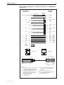
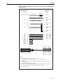
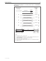
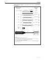
Cables And Loopback Plugs ............................................................................ 75
Transition Cables for Network Interfaces ................................................... 75
ISDN Interface Cables ............................................................................... 83
Terminal and Modem Cables .................................................................... 84
Transceivers and AUI Cables ..................................................................... 88
C613-03058-00 REV A
4
AR Router
Loopback Plugs for Testing Interfaces ....................................................... 90
PICs and NSMs ............................................................................................... 93
Restricted Procedures ...................................................................................... 94
Installing a MAC ....................................................................................... 94
Installing a PAC ........................................................................................ 98
Installing a Flash SIMM ........................................................................... 104
AT-AR720 Dip Switch Settings ................................................................ 105
Diagnostics ............................................................................................. 106
Replacing Boot EPROMs ......................................................................... 108
Contacting Us ............................................................................................... 110
C613-03058-00 REV A
Hardware Reference
5
Introduction
This Hardware Reference describes the hardware features of all AR300, AR400,
and AR700 Series router models, including information on Mini Accelerator
Cards (MACs) and PCI Accelerator Cards (PACs). Hardware and installation
information for Port Interface Cards (PICs) and Network Service Modules
(NSMs) can be found in their respective Quick Install Guides and Hardware
References.
This Reference does not cover software configuration or software installation
procedures. For information on software, refer to your router’s Software Reference.
This Reference does not cover AR100 Series routers. For information on AR100 Series
routers, refer to the AR100 Series Internet Router User Guide or AR100 Series Internet
Router Software Reference. These documents can be found on the CD-ROM packaged
with your AR100 Series router, or at www.alliedtelesyn.co.nz/support/ar100/
index.html.
AR300 Series routers have fixed interface configurations and do not have
expansion capabilities. Some AR400 Series routers and all AR700 Series routers
have expansion bays that accommodate Port Interface Cards (PICs), which
provide additional or new interfaces. The AT-AR740 and AT-AR745 routers
also have an expansion bay to accommodate a Network Service Module (NSM),
which either directly provides further interfaces, or provides multiple slots
where additional PIC interfaces can be added.
AR300 Series routers, AR400 Series routers, AR720 and AR740 routers have a
dedicated Mini Accelerator Card (MAC) slot that accommodates special
purpose MAC coprocessor cards. MAC cards provide additional functionality
or performance, such as compression or encryption, but do not add extra
interfaces.
In addition to a MAC slot, AR740 routers also have a PCI Accelerator Card
(PAC) slot. This slot accommodates PACs. Like MACs, PACs provide
additional compression and encryption functionality, but do so through a high
performance PCI bus.
The AR725 and AR745 routers have a PAC slot only.
C613-03058-00 REV A
6
AR Router
Models Covered By This Reference
This Hardware Reference includes information on the following models:
■
AR300L(S)
■
AR300(S)
■
AR310(S)
■
AR320
■
AR330
■
AR350
■
AR370(S)
■
AR370(U)
■
AR390
■
AR395
■
AR410
■
AR410S
■
AR720
■
AR725
■
AR740
■
AR745
Hardware Reference updates can be found at www.alliedtelesyn.co.nz/
documentation/documentation.html.
Where To Find More Information
The Documentation and Tools CD-ROM bundled with each router contains the
complete Document Set for your router and, where applicable, its expansion
options. The CD-ROM also includes tools for managing your router.
The Document Set includes:
■
The Safety Booklet for your router, which provides safety and statutory
information.
■
The Quick Install Guide for your router, which outlines how to install the
router.
■
The Quick Start Guide or User Guide for your router, which describes basic
configuration procedures.
■
The AR Router Hardware Reference for your router, which provides detailed
information on the hardware features of AR routers.
■
The Software Reference for your router, which provides detailed information
on configuring the router and its software.
■
AT-TFTP Server for Windows, for downloading software releases.
■
Adobe Acrobat Reader, for viewing online documentation.
■
Microsoft Internet Explorer.
C613-03058-00 REV A
Hardware Reference
7
The following documents are included if your router has PIC bays or an NSM
bay:
■
The Port Interface Card Quick Install Guide, which outlines the procedure for
installing PICs; and the Port Interface Card Hardware Reference, which
provides detailed information on PICs.
The following documents are included if your router has an NSM bay:
■
The Network Service Module Quick Install Guide, which outlines the
procedure for installing an NSM; and the Network Service Module Hardware
Reference, which provides detailed information on NSMs.
These documents can also be downloaded from the AR Router Support Site at
www.alliedtelesyn.co.nz/documentation/documentation.html.
For information on AR100 Series routers, refer to the AR100 Series Internet Router
User Guide or AR100 Series Internet Router Software Reference. These documents can
be found on the CD-ROM shipped with your AR100 Series router, or at
www.alliedtelesyn.co.nz/support/ar100/index.html.
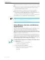
Using Windows Terminal and Windows
Hyperterminal
You can use a PC running terminal emulation software as the manager console,
instead of a terminal. There are many terminal emulation applications
available for the PC, but the most readily available are the Terminal and
HyperTerminal applications included in Microsoft Windows 95, 98, 2000, and
Windows NT 4.0. In standard Windows installations, HyperTerminal is located
in the Start > Programs > Accessories menu.
The key to successful use of terminal emulation software with the router is to
configure the software and router with matching communications parameters.
The following procedures describe how to configure Windows Terminal and
HyperTerminal for the default RS-232 Terminal Port settings on the router, but
the same principles apply to other terminal emulation programs.
To configure Windows HyperTerminal for Windows 95, 98, 2000, & NT 4.0.
1.
2.
C613-03058-00 REV A
In Windows, select:
•
Programs > Accessories > HyperTerminal.
•
Double-click the Hypertrm.exe icon.
In the Connection Description dialog box:
•
Enter a name for the connection (e.g., AR300LS)
•
Select an icon from the scrolling list.
•
Click “OK”.
8
AR Router
3.
In the Phone Number dialog box:
From the “Connect using:” drop-down list, select:
4.
•
“Direct to Com n” Where “COM n” is the COM port on the PC used to
connect to the router.
•
Click “OK”.
In the COMn Properties dialog box, set:
•
“Bits per second” to 9600.
•
“Data bits” to 8.
•
“Parity” to None.
•
“Stop bits” to 1.
•
“Flow control” to Hardware.
•
Click “OK”.
C613-03058-00 REV A
Hardware Reference
9
5.
From the File menu, select:
•
“Properties”
In the Connection Properties dialog box, click the Settings tab and set:
6.
•
“Function, arrow, and ctrl keys act as” to “Terminal keys”
•
“Emulation” to VT100.
Click “ASCII Setup” to display the ASCII Setup dialog box. Uncheck:
•
“Echo typed characters locally”.
•
“Append line feeds to incoming line ends”.
Set other parameters as required.
•
C613-03058-00 REV A
Click “OK” twice to close all dialog boxes.
10
AR Router
7.
Save the current session. From the File menu, select:
•
“Save”.
This creates a connection icon with the name you assigned in the
HyperTerminal group. To use the configuration:
•
Double-click the connection icon in the HyperTerminal group.
When the HyperTerminal window appears, press:
•
[Enter] a couple of times.
The router’s log in prompt will appear.
Router Start-up
At start-up, the manager can choose to run either the software release stored in
EPROM or flash (depending on the model of router), or the software release
specified by the INSTALL parameters previously set using the SET INSTALL
command. (AR300 Series routers, AR720, and AR740 routers boot from
EPROM, while AR400 Series routers, AR725 and AR745 routers boot from
flash.)
All code is executed out of system DRAM. At power-up the boot code is loaded
from EPROM (or flash for AR400s, the AR725 and AR745) to DRAM. The boot
code checks the INSTALL information then reloads DRAM with the selected
temporary, preferred, or default install release (which is stored in flash) and runs
this code.
If the install release is a compressed release, the release is uncompressed as it
loads to DRAM. This may take 20–30 seconds. At this point, any required
patches are loaded from flash. If a patch is compressed, it is uncompressed as it
loads to DRAM. This procedure ensures that the code runs at maximum speed
(DRAM is faster than EPROM), and allows updates to be made to the code.
Updates can be downloaded over the network from a TFTP server and stored
in flash until required at power-up.
See the Software Reference (Chapter 1, Operation), for a description of the downline
loading method. The code can also be loaded from the flash memory, under user control.
The Operation chapter also has a detailed description of flash memory.
All router software, patches, and configuration settings are stored as files in
flash memory. Typically, the following files will be present in flash:
■
The current installed software release. Additional software releases may
also be present.
■
The current installed patch, if any. Additional patches may also be present.
■
The online help file. All online help is stored in a language independent
text file. Users can create and install their own online help file, to support
different languages or to provide site-specific information.
■
The boot script boot.cfg. The boot script contains standard router
commands (executed on start-up to configure the router).
■
Additional user-defined configuration scripts containing commands to
configure the router for different functions. These scripts are created using
the built-in editor, the ADD SCRIPT command, Scripting, or the CREATE
CONFIG command.
C613-03058-00 REV A
Hardware Reference
11
All configuration information is stored in flash memory as configuration scripts. these
scripts contain standard router commands. When a configuration command is entered
at the command prompt from a terminal, terminal emulation program, or Telnet session,
the command only alters the dynamic configuration. This is not saved over a power
cycle. To ensure that configuration changes resulting from such commands are retained
across a power cycle, the dynamic configuration must be saved as a configuration script,
using the CREATE CONFIG command.
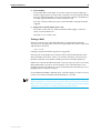
When the router starts up following either a power cycle or an operatorinitiated reboot (using the RESTART command), the following sequence of
operations is performed:
1.
Perform start-up self tests.
2.
Load the EPROM release as the INSTALL boot into the router’s RAM.
3.
Prompt the manager for changes to the default start-up procedure:
Force EPROM download (Y)?
The manager may press one of the keys listed in Table 1 on page 12 to
override the default installation procedure.
4.
Check the INSTALL information to determine which release to load and
run, according to the INSTALL parameters, and the manager’s response to
the previous prompt. If none of the keys in Table 1 on page 12 are pressed,
the INSTALL parameters determine which release and patch are loaded and
run.
5.
Load the required EPROM or flash release specified by the INSTALL
parameters as the main boot.
6.
Start the router.
7.
Execute the boot script (boot.scp), if one has been configured.
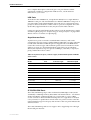
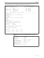
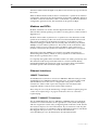
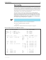
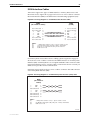
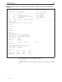
A series of start-up messages is sent to Port 0 (The console or terminal port).
Figure1: Router start-up messages.
INFO:
INFO:
PASS:
INFO:
PASS:
PASS:
INFO:
INFO:
Force
INFO:
INFO:
INFO:
Self tests beginning.
RAM test beginning.
RAM test, 4096k bytes found.
BBR tests beginning.
BBR test, 128k bytes found.
BBR test. Battery OK.
Self tests complete
Downloading router software.
EPROM download (Y) ?
Initial download succeeded
Executing configuration script <boot.cfg>
Router startup complete
Manager >
C613-03058-00 REV A
12
AR Router
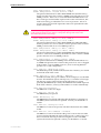
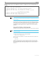
After the self tests are complete, the manager is given the option of forcing a
mandatory boot from the EPROM release. The message:
Force EPROM download (Y)?
is displayed on the terminal connected to the console port (port 0) and the
router pauses. If a key is not pressed within a few seconds, the start-up process
continues and all steps in the start-up sequence are executed. Pressing selected
keys on the terminal immediately after the “Force EPROM download” message
is displayed will change the router start-up process (Table 1 on page 12).
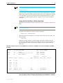
Table 1: Router start-up sequence keystrokes.
Pressing key...
Forces the router to...
(no key pressed) After a few seconds, the router start up process continues.
[Y]
Load the release, without any patches, from EPROM onto the RAM, and
run the full release. Go to step 6.
[S]
Load and run the release and patch determined by the INSTALL
parameters from flash, ignoring any boot script or any previous
configuration stored in NVS.
[N]
Load from flash to RAM the release and patch determined by the INSTALL
parameters, and run using the current configuration stored in NVS (if
any), ignoring any boot script.
[Ctrl/D]
Authorised
service engineers
only
Enter diagnostics mode.
Warning. Using this option may cause the router to cease functioning,
may invalidate the product warranty, and may be a breach of the product
licence agreement (“Diagnostics” on page A-15).
During the start-up process the router will generate four different types of
messages. All messages are preceded by one of the words INFO, PASS, FAIL,
or ERROR. The meaning of these words in the context of the messages is
shown in Table 2 on page 12.
Table 2: Router start-up message classes.
Message
Meaning
INFO
An informational message that an action has been taken by the system.
PASS
An informational message that a test has been completed successfully.
ERROR
An error message that a test has failed, but the system will continue to
operate.
FAIL
An error message that a fatal error condition has caused the system to
halt in an unrecoverable fashion.
The possible messages and their meanings are:
INFO: Self tests beginning.
The code loader tests are about to begin.
INFO: RAM test beginning.
The RAM tests are about to begin.
C613-03058-00 REV A
Hardware Reference
13
FAIL: RAM presence, invalid PD bits, SIMM 0.
ERROR: RAM presence, invalid PD bits, SIMM 1.
The presence detect bits for either RAM SIMM stick (Flash memory)
had an invalid value. This is fatal for SIMM position 0 and an error for
SIMM position 1. If this error occurs then the RAM SIMM stick is not
the correct type and should be replaced. The router will function, but
with less memory, provided the error occurs in position 1. Errors in
position 0 are fatal and will require the stick to be replaced before the
router will function.
Unauthorised opening of the router lid may expose you to live components and
a risk of injury from electric shock, it may also damage the router and
invalidate the product warranty.
FAIL: RAM presence, memory too slow, SIMM 0.
ERROR: RAM presence, memory too slow, SIMM 1.
The presence detect bits for either RAM SIMM stick indicated 100ns
memory, which is too slow for effective router operation. This is fatal for
SIMM position 0 and an error for SIMM position 1.
FAIL: RAM presence, memory too small, SIMM 0.
ERROR: RAM presence, memory too small, SIMM 1.
The presence detect bits for either RAM SIMM stick indicated memory
that is too small to be handled by the hardware. This is fatal for SIMM
position 0 and an error for SIMM position 1.
FAIL: RAM presence, no memory present, SIMM 0.
The presence detect bits for SIMM position 0 indicated that there was
no SIMM stick present. This is fatal for this position. No error is flagged
if this pattern occurs in SIMM position 1, since not having RAM in
position 1 is a valid configuration.
PASS: RAM test, 2048k bytes found.
The RAM test passed, and the indicated amount of memory was found
and will be used in the router.
ERROR: RAM test 5. Error address = 00345678.
A RAM test failed, at the given address. In the example, it was the fifth
test run. The RAM test repeats until it passes, so a number of messages
like this may appear. This fault means that the memory system
(probably the SIMM stick) is faulty. The SIMM stick should be replaced.
If the fault continues, contact your distributor or reseller immediately.
INFO: BBR tests beginning.
The BBR tests are about to begin.
PASS: BBR test. Battery OK.
The BBR battery test passed.
ERROR: BBR Battery low.
The BBR battery test failed, indicating that the battery is running low.
The BBR system will need to be replaced. Contact your distributor or
reseller.
PASS: BBR test, 256k bytes found.
The BBR size/location test passed, with the indicated amount of BBR
found.
FAIL: BBR test. Error address = 12345678.
The BBR size/location test failed at the given location. The test at this
location failed, indicating the end of memory, but a valid location was
discovered in the 255 long words following this location. The BBR
system will need to be replaced. Contact your distributor or reseller.
C613-03058-00 REV A
14
AR Router
FAIL: BBR test, only 16k bytes found.
The BBR size/location test completed, but only the displayed amount
of memory was found. This amount is less than the minimum required
to run the router software.
INFO: Self tests complete.
The start-up tests have finished.
INFO: Downloading router software.
The process of downloading the router software and vector table from
ROM is about to begin.
ERROR: Code load retried.
FAIL: Code load failed.
The load of the code from ROM to RAM failed. The load is retried a
number of times. Each time a failure occurs the ERROR message is
displayed. If the maximum number of attempts is reached, the FAIL
message is displayed.
ERROR: Vector load retried.
FAIL: Vector load failed.
The load of the vector table from ROM to RAM failed. The load is
retried a number of times. Each time a failure occurs the ERROR
message is displayed. If the maximum number of attempts is reached,
the FAIL message is displayed. Contact your authorised Allied Telesyn
distributor or reseller.
INFO: Initial download succeeded.
The start-up tests and download are complete, and the router software
is about to be started. If the default install is a compressed release, the
release will now be decompressed. This may take a few seconds.
INFO: Downloading compressed release. This may take up to 1
minute...
INFO: Loading software into memory. This may take up to 1
minute...
The main router software is about to be loaded into RAM. If the release
is a compressed release, the release will be decompressed.
FAIL: Unexpected exception. Offset = 40, Addr = 0100045e.
An unexpected exception occurred while the start-up was executing.
The vector offset and the program counter when the exception occurred
are given in the message. Contact your distributor or reseller.
INFO: Executing configuration script <script-name>
The configuration commands stored in <script-name> are being
executed. If an error is found in the script, one or more ERROR
messages will be displayed.
INFO: Router startup complete.
The start-up process is complete and the router is now operational.
C613-03058-00 REV A
Hardware Reference
15
Online Documentation
This section provides a step-by-step guide to accessing online documentation.
Adobe Acrobat Reader must be installed to view the online documentation.
To Access Online Documentation
To use the CD-ROM, follow these steps:
1.
Insert your router’s Documentation and Tools CD-ROM in the CD-ROM drive.
2.
If the Welcome screen does not appear.
Select "Run" from the Start Menu (Windows 95, 98, 2000 or NT 4.0).
Type d:\start.exe (where d: is the CD-ROM drive letter) and click OK.
3.
To view a document.
Click on the document title.
4.
To navigate around PDF documents.
Use the toolbar buttons, keyboard shortcuts, or commands from the
Document menu to page through the document.
Click on a bookmark, thumbnail or hypertext link to jump to a specific
section or topic.
Use the Search command to search for keywords or phrases.
For more information about using the Adobe Acrobat Reader, select
"Reader Guide" from the Help menu.
5.
To install any of the tools included on the CD-ROM.
Click on a link in the Welcome screen.
AT-TFTP Server
This section provides information on how to access and use AT-TFTP Server.
AT-TFTP Server can be used to transfer configuration files as well as to
download software patches and releases.
To use AT-TFTP Server, follow these steps:
1.
If AT-TFTP Server has not yet been installed.
Install it now from the your router’s Documentation and Tools CD-ROM.
To install AT-TFTP server:
Choose AT-TFTP Server from the Start > Programs > Allied Telesyn > ATTFTP Server menu.
2.
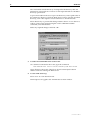
To set preferences for the AT-TFTP Server.
Select "Options" from the File menu to display the "Set Preferences" dialog
box.
C613-03058-00 REV A
16
AR Router
The "Default file transfer directory" field specifies the directory that ATTFTP Server will read from or write to for file requests that do not include a
directory specification.
To prevent unauthorised access to private directories, enter a path name in
the "Restrict to directory" field. AT-TFTP Server will use only the specified
directory, even if file requests contain references to other directories.
Select "Read only" to prevent files being written to the PC. To use the PC to
archive router scripts created using the router's CREATE CONFIG
command, select "Read Write".
Make any required changes and click "OK".
3.
To load a file from AT-TFTP Server to the router.
On a terminal connected to the router, type the command:
LOAD METHOD=TFTP FILE=filename SERVER=ipadd DEST=FLASH
where filename is the name of the file to download and ipadd is the IP
address of the PC running AT-TFTP Server.
4.
To save a TFTP Server log.
Select "Save As" from the File menu.
TFTP requests are logged to the AT-TFTP Server main window.
C613-03058-00 REV A
Hardware Reference
17
Memory
All AR300 Series routers, except the AR390 and AR395, have 8MB of fixed
(non-expandable) DRAM. The AR390, AR395, AR410, AR410S, AR720, and
AR740 routers have 16MB of fixed (non-expandable) DRAM.
The AR725 and AR745 routers have 128MB of SDRAM DIMMs. Other sizes are
supported, e.g. 256 and 512MB, see your authorised Allied Telesyn distributor
or reseller for upgrade options. Other supplier’s DIMMs are not approved, and
therefore not supported, but may function correctly. AR725 and AR745 routers
also have a slot for compact flash cards. See “Flash Memory” on page 63 for
more information on flash memory.
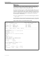
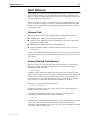
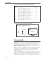
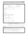
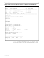
The amount of DRAM present in a router can be checked using the command:
SHOW SYSTEM
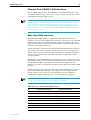
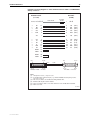
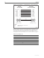
This will produce a display like that shown in Figure 2 on page 17. The DRAM
and FLASH fields show the amounts of DRAM and flash memory, respectively.
Figure2: Example output from the SHOW SYSTEM command.
Router System Status
Time 17:10:06 Date 25-Sep-1999.
Board
ID Bay Board Name
Rev
Serial number
-------------------------------------------------------------------------------Base
62
AR720
M1-0 6845218
IC Module 40
0 AR022 PIC Eth
M2-0 6844595
IC Module 38
1 AR023 PIC Sync
M1-1 6844715
MAC
67
AR012 CMAC
M2-0 33636409
-------------------------------------------------------------------------------Memory DRAM : 16384 kB
FLASH : 4096 kB
-------------------------------------------------------------------------------SysDescription
CentreCOM AR720 version 1.8.1-00 08-Sep-1999
SysContact
David Johns, ext 8331
SysLocation
Laboratory, First Floor, Head Office Building
SysName
LAB
SysUpTime
250074 ( 00:41:40 )
Software Version: 1.8.1-00 08-Sep-1999
Release Version : 1.8.1-00 08-Sep-1999
Patch Installed : NONE
Territory
: europe
Help File
: help.hlp
Boot configuration file: load.cfg (exists)
Current configuration: load.cfg
Security Mode
: Disabled
Patch files
Name
Device
Size
Version
-------------------------------------------52772-02.paz
flash
94856
7.7.2-2
--------------------------------------------
C613-03058-00 REV A
18
AR Router
AR300 Series Routers
The AR300 Series comprises a family of fixed function routers. Models are
distinguished by the type of WAN port on the base CPU card and the number
of analogue voice ports supported (Tabl e3 on page 18).
Table 3: Interface configurations for AR300 Series routers.
AR300 Series
Model
Ethernet LAN Asynchronous
Ports
Ports
ISDN Ports
Synchronous
Ports1
Analogue
Voice Ports
Expansion
Capabilities
AT-AR300L(S)
1
1
1 BRI S/T
(2 B + 1 D)
-
-
1 MAC card slot
AT-AR300(S)
1
1
1 BRI S/T
(2 B + 1 D)
-
2
1 MAC card slot
AT-AR310(S)
1
1
1 BRI S/T
(2 B + 1 D)
-
4
1 MAC card slot
AT-AR320
2
2
-
-
-
1 MAC card slot
AT-AR330
2
2
-
1
-
1 MAC card slot
AT-AR350
1
2
-
1
-
1 MAC card slot
AT-AR370(S)
1
2
2 BRI S/T
(2 B + 1 D)2
1
-
1 MAC card slot
AT-AR370(U)
1
2
1 BRI U
(2 B + 1 D)
1
-
1 MAC card slot
AT-AR390
1
2
1 G.7033
-
-
1 MAC card slot
AT-AR395
1
2
1 PRI
(30 B + 1 D)
-
-
1 MAC card slot
1. Universal AMPLIMITE connector supports RS-232/V.28, V.25 and X.21 standards in both DTE and DCE modes.
2. BRI interfaces are daisy-chained to allow multiple ISDN devices to be connected to the S/T bus.
3. 1 × 2048Kbps or n × 64Kbps.
AR300 Series routers have the following standard interfaces:
■
0, 1, or 2 WAN ports. All models except the AT-AR320 have an ISDN Basic
Rate S/T or U port and/or a synchronous port, or a G.703/Primary Rate
ISDN port. The AT-AR320 has no WAN ports.
■
1 or 2 asynchronous ports with DB9 connectors. The AT-AR300L(S),
AT-AR300(S) and AT-AR310(S) have female connectors. All other models
have male connectors.
■
1 Ethernet LAN 10BASE-T port (except the AT-AR320 and AT-AR330 ,
which have two Ethernet LAN 10BASE-T ports).
■
Voice ports, on the AT-AR300(S) and AT-AR310(S).
In addition, AR300 Series routers have a dedicated MAC slot which can
accommodate any of the following MACs:
■
AT-AR010 EMAC, Encryption MAC.
■
AT-AR011 ECMAC Compression/Encryption MAC
■
AT-AR011 V2 ECMAC Compression/Encryption MAC.
■
AT-AR012 CMAC, Compression MAC.
C613-03058-00 REV A
Hardware Reference
19
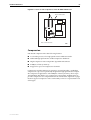
Front and Rear Panels
The following figures and tables show the front and rear panels, and the
functions of the front panel LEDs, for each AR300 Series router.
AR300 Series Model
Front and Rear Panel View
LED Functions
AT-AR300L(S)
AT-AR300(S)
AT-AR310(S)
Figure 3 on page 19
Table 4 on page 20
AT-AR320
AT-AR330
Figure 4 on page 20
Table 5 on page 21
AT-AR350
Figure 5 on page 21
Table 6 on page 22
AT-AR370(S)
Figure 6 on page 22
Table 7 on page 23
AT-AR370(U)
Figure 7 on page 23
Table 8 on page 24
AT-AR390
AT-AR395
Figure 8 on page 24
Table 9 on page 25
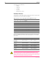
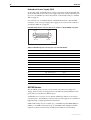
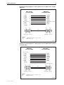
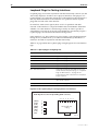
The AT-AR300L(S), AT-AR300(S), and AT-AR310(S) are identical except for the
number of voice ports. The AT-AR300L(S) has no voice ports. The AT-AR300(S)
has two voice ports. And the AT-AR310(S) has four voice ports.
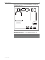
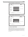
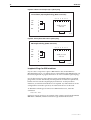
The AT-AR320 and AT-AR330 router are identical, except that the AT-AR330
has a synchronous port.
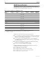
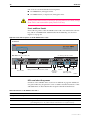
Figure3: Front and rear panels of the AT-AR300L(S)/AT-AR300(S)/AT-AR310(S) router.
B1
AC
TIV
B2
AR310
Access Router
E
Model name
LINK
TRA
NSM
IT
CO
LLIS
REC ION
EIV
E
Front Panel
SYSTEM
10BASE-T
RUN
POWER
ISDN
LEDs
Rear Panel
VOICE 3
VOICE 2
100–240 VAC, 50–60Hz, 300mA.
PORT 1 (RS232)
AR310
ETHERNET 0
PORT 0 (RS232)
BRI 0
CONFIG
MDX
1
VOICE 1
VOICE 0
Voice (PBX) ports
HUB
2
3
4
PC
Ethernet port
DISCONNECT MAINS SUPPLY BEFORE REMOVING LID
NO USER SERVICEABLE PARTS
Asynchronous
ports
DIP
switch
Basic Rate ISDN
interface
Power inlet
310FRP
C613-03058-00 REV A
20
AR Router
Table 4: Functions of the front panel LEDs on the AT-AR300L(S)/AT-AR300(S)/
AT-AR310(S) router.
LED
Function
LAN Link
Lit when the Ethernet interface is connected to a device (e.g., a hub),
which is generating link pulses. This LED is normally lit.
LAN Txd
Lit when data is being transmitted over the Ethernet interface.
LAN Coll (yellow) Lit when a collision is detected on the Ethernet interface.
LAN Rxd
Lit when data is being received on the Ethernet interface.
ISDN B2
Lit when data or voice calls are being transmitted over the B2 channel
of the ISDN interface.
ISDN B1
Lit when data or voice calls are being transmitted over the B1 channel
of the ISDN interface.
ISDN Active
Lit when the BRI has successfully completed the exchange of INFO 1 and
INFO 2 signals, and INFO 3 and INFO 4 signals are present on the link.
This means that the ISDN interface is correctly connected to a working
NT device.
System (red)
This LED is not normally lit. It is used to signal various system conditions
(e.g., when the processor executes the reboot sequence). Generally it
signals a possible fault condition, but it will light briefly during powerup and operator initiated reboot.
Run
Lit when the internal processor is executing code. If the processor stops
for any reason (a fault condition), then the LED will not be lit.
Power
Lit when power is supplied and the router is switched on.
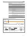
Figure4: Front and rear panels of the AT-AR320/AT-AR330 router.
E
TXD
AC
TIV
AR330
Access Router
RXD
DAT
A1
LINK
1
DAT
A0
LIN
K0
Model name
Front Panel
SYSTEM
10BASE-T
RUN
POWER
WAN
LEDs
Rear Panel
AR330
ETHERNET 1
100–240 VAC, 50–60Hz, 300mA.
PORT 1 (RS232)
SYNCHRONOUS 0
PORT 0 (RS232)
MDX
ETHERNET 0
CONFIG
MDX
1
HUB
Ethernet port
PC
HUB
Asynchronous
ports
Ethernet port
2
3
4
PC
DISCONNECT MAINS SUPPLY BEFORE REMOVING LID
NO USER SERVICEABLE PARTS
DIP
switch
Synchronous port
Power inlet
330FRP
C613-03058-00 REV A
Hardware Reference
21
Table 5: Functions of the front panel LEDs on the AT-AR320/AT-AR330 router .
LED
Function
LAN Data 1
Lit when data is being transmitted over the Ethernet 1 interface.
LAN Link 1
Lit when the Ethernet 1 interface is connected to a device (e.g., a hub),
which is generating link pulses. This LED is normally lit.
LAN Data 0
Lit when data is being transmitted over the Ethernet 0 interface.
LAN Link 0
Lit when the Ethernet 0 interface is connected to a device (e.g., a hub),
which is generating link pulses. This LED is normally lit.
WAN Rxd
Lit when data is being received over the synchronous interface.
WAN Txd
Lit when data is being transmitted over the synchronous interface.
WAN Active
Lit when a higher layer module (e.g., PPP) has attached to the interface
and DCD or its analog (“I” for X.21) is active. This usually indicates that
the NTU or DSU/CSU is connected to a correctly provisioned data circuit.
System (red)
This LED is not normally lit. It is used to signal various system conditions
(e.g., when the processor executes the reboot sequence). Generally it
signals a possible fault condition, but it will light briefly during powerup and operator initiated reboot.
Run
Lit when the internal processor is executing code. If the processor stops
for any reason (a fault condition), then the LED will not be lit.
Power
Lit when power is supplied and the router is switched on.
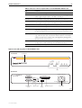
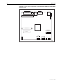
Figure5: Front and rear panels of the AT-AR350 router.
TXD
AC
TIV
RXD
AR350
Access Router
E
Model name
LINK
TRA
NSM
IT
CO
LLIS
REC ION
EIV
E
Front Panel
SYSTEM
10BASE-T
RUN
POWER
WAN
LEDs
Rear Panel
AR350
100–240 VAC, 50–60Hz, 300mA.
PORT 1 (RS232)
SYNCHRONOUS 0
PORT 0 (RS232)
ETHERNET 0
CONFIG
MDX
1
HUB
Asynchronous
ports
Ethernet port
2
3
4
PC
DISCONNECT MAINS SUPPLY BEFORE REMOVING LID
NO USER SERVICEABLE PARTS
DIP
switch
Synchronous port
Power inlet
350FRP
C613-03058-00 REV A
22
AR Router
Table 6: Functions of the front panel LEDs on the AT-AR350 router .
LED
Function
LAN Link
Lit when the Ethernet interface is connected to a device (e.g., a hub),
which is generating link pulses. This LED is normally lit.
LAN Txd
Lit when data is being transmitted over the Ethernet interface.
LAN Coll (yellow) Lit when a collision is detected on the Ethernet interface.
LAN Rxd
Lit when data is being received on the Ethernet interface.
WAN Rxd
Lit when data is being received over the synchronous interface.
WAN Txd
Lit when data is being transmitted over the synchronous interface.
WAN Active
Lit when a higher layer module (e.g., PPP) has attached to the interface
and DCD or its analog (“I” for X.21) is active. This usually indicates that
the NTU or DSU/CSU is connected to a correctly provisioned data circuit.
System (red)
This LED is not normally lit. It is used to signal various system conditions
(e.g., when the processor executes the reboot sequence). Generally it
signals a possible fault condition, but it will light briefly during powerup and operator initiated reboot.
Run
Lit when the internal processor is executing code. If the processor stops
for any reason (a fault condition), then the LED will not be lit.
Power
Lit when power is supplied and the router is switched on.
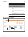
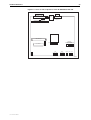
Figure6: Front and rear panels of the AT-AR370(S) router.
E
ISD
N
AC
TIV
AR370
Access Router
SYN
LINK
TRA
NSM
IT
CO
LLIS
REC ION
EIV
E
Model name
Front Panel
SYSTEM
10BASE-T
RUN
POWER
WAN
LEDs
Rear Panel
AR370
100–240 VAC, 50–60Hz, 300mA.
PORT 1 (RS232)
SYNCHRONOUS 0
ISDN
BRI 0
S/T BUS
PORT 0 (RS232)
ETHERNET 0
CONFIG
MDX
1
To Network
HUB
Other Devices
BRI ISDN Port
Asynchronous
ports
Ethernet port
2
3
4
PC
DISCONNECT MAINS SUPPLY BEFORE REMOVING LID
NO USER SERVICEABLE PARTS
DIP
switch
Synchronous port
Power inlet
370SFRP
C613-03058-00 REV A
Hardware Reference
23
Table 7: Functions of the front panel LEDs on the AT-AR370(S) router .
LED
Function
LAN Link
Lit when the Ethernet interface is connected to a device (e.g., a hub),
which is generating link pulses. This LED is normally lit.
LAN Txd
Lit when data is being transmitted over the Ethernet interface.
LAN Coll (yellow) Lit when a collision is detected on the Ethernet interface.
LAN Rxd
Lit when data is being received on the Ethernet interface.
WAN Syn
Lit when data is being transmitted or received over the synchronous
interface.
WAN ISDN
Lit when data is being transmitted or received over the ISDN interface.
WAN Active
Lit when the BRI has successfully completed the exchange of INFO 1 and
INFO 2 signals, and INFO 3 and INFO 4 signals are present on the link.
This means that the ISDN interface is correctly connected to a working
NT device.
System (red)
This LED is not normally lit. It is used to signal various system conditions
(e.g., when the processor executes the reboot sequence). Generally it
signals a possible fault condition, but it will light briefly during powerup and operator initiated reboot.
Run
Lit when the internal processor is executing code. If the processor stops
for any reason (a fault condition), then the LED will not be lit.
Power
Lit when power is supplied and the router is switched on.
Figure7: Front and rear panels of the AT-AR370(U) router.
E
ISD
N
AC
TIV
AR370
Access Router
SYN
LINK
TRA
NSM
IT
CO
LLIS
REC ION
EIV
E
Model name
Front Panel
SYSTEM
10BASE-T
RUN
POWER
WAN
LEDs
Rear Panel
AR370
ISDN-U BRI 0
100–240 VAC, 50–60Hz, 300mA.
PORT 1 (RS232)
SYNCHRONOUS 0
PORT 0 (RS232)
ETHERNET 0
CONFIG
MDX
1
HUB
BRI-U ISDN Port
Asynchronous
ports
Ethernet port
2
3
4
PC
DISCONNECT MAINS SUPPLY BEFORE REMOVING LID
NO USER SERVICEABLE PARTS
DIP
switch
Synchronous port
Power inlet
370UFRP
C613-03058-00 REV A
24
AR Router
Table 8: Functions of the front panel LEDs on the AT-AR370(U) router .
LED
Function
LAN Link
Lit when the Ethernet interface is connected to a device (e.g., a hub),
which is generating link pulses. This LED is normally lit.
LAN Txd
Lit when data is being transmitted over the Ethernet interface.
LAN Coll (yellow) Lit when a collision is detected on the Ethernet interface.
LAN Rxd
Lit when data is being received on the Ethernet interface.
WAN Syn
Lit when data is being transmitted or received over the synchronous
interface.
WAN ISDN
Lit when data is being transmitted or received over the ISDN interface.
WAN Active
Lit when the U interface is in the Activated state (i.e., it is fully
operational at layer 1).
System (red)
This LED is not normally lit. It is used to signal various system conditions
(e.g., when the processor executes the reboot sequence). Generally it
signals a possible fault condition, but it will light briefly during powerup and operator initiated reboot.
Run
Lit when the internal processor is executing code. If the processor stops
for any reason (a fault condition), then the LED will not be lit.
Power
Lit when power is supplied and the router is switched on.
Figure8: Front and rear panels of the AT-AR390 and AT-AR395 routers.
E
TXD
AC
TIV
AR390
Access Router
RXD
LINK
TRA
NSM
IT
CO
LLIS
REC ION
EIV
E
Model name
Front Panel
SYSTEM
10BASE-T
RUN
POWER
WAN
LEDs
Rear Panel
100–240 VAC, 50–60Hz, 300mA.
AR390
CONFIG
PORT 1 (RS232)
ETHERNET 0
PRI 0
MDX
1
2
3
4
PORT 0 (RS232)
DIP
switch
Asynchronous
ports
HUB
Ethernet port
PC
120Ω
75Ω Tx
120Ω
G.703/PRI ISDN port
75Ω Rx
DISCONNECT MAINS SUPPLY BEFORE REMOVING LID
NO USER SERVICEABLE PARTS
Power inlet
AR390FRP
C613-03058-00 REV A
Hardware Reference
25
Table 9: Functions of the front and rear panel LEDs on the AT-AR390 and AT-AR395
routers.
LED
Function
LAN Link
Lit when the Ethernet interface is connected to a device (e.g., a hub),
which is generating link pulses. This LED is normally lit.
LAN Txd
Lit when data is being transmitted over the Ethernet interface.
LAN Coll (yellow) Lit when a collision is detected on the Ethernet interface.
LAN Rxd
Lit when data is being received on the Ethernet interface.
WAN Rxd
Lit when data is being transmitted over the G.703/PRI ISDN interface.
WAN Txd
Lit when data is being transmitted over the G.703/PRI ISDN interface.
WAN Active
Lit whenever operational (i.e., no RAI or AIS set) frames are being
received on the G.703/PRI ISDN interface.
System (red)
This LED is not normally lit. It is used to signal various system conditions
(e.g., when the processor executes the reboot sequence). Generally it
signals a possible fault condition, but it will light briefly during powerup and operator initiated reboot.
Run
Lit when the internal processor is executing code. If the processor stops
for any reason (a fault condition), then the LED will not be lit.
Power
Lit when power is supplied and the router is switched on.
120Ω (rear panel) Lit when the 120Ω interface type is selected via the push button.
The Main System
The main features of the AR300 Series base CPU card are:
■
68360 processor.
■
512K of EPROM.
■
8 MBytes of DRAM.
■
2 MBytes of flash memory.
■
1 or 2 Ethernet LAN 10BASE-T ports.
■
1 or 2 RS-232 asynchronous serial ports.
■
1 Basic Rate ISDN S/T port, on models AT-AR300L(S), AT-AR300(S) and
AT-AR310(S).
■
1 Basic Rate ISDN U interface port on model AT-AR370(U).
■
1 G.703/Primary Rate ISDN port, on models AT-AR390 and AT-AR395.
■
1 high speed synchronous serial port, on models AT-AR350, AT-AR370(S),
and AR370(U).
■
0, 2, or 4 analogue voice ports.
■
1 MAC compression/encryption card slot.
The asynchronous serial ports can be used as general purpose ports for
terminals, printers, or modems. Port 0 can optionally be used for diagnostics or
can automatically output the router start-up messages, by altering the DIP
switch settings described in Table 10 on page 26.
C613-03058-00 REV A
26
AR Router
Set asynchronous port default to:
•
9600 bps
•
8 data bits
•
1 stop bit
•
No parity
•
Hardware flow control.
Hardware Features
All models have a DIP switch, which is located on the router’s rear panel. DIP
switch functions are shown in Table 10 on page 26.
Table 10: Functions of the rear panel DIP switch on AR300 Series routers .
DIP Switch Settings
1
2
3
4
Function
Any
Any
Any
On
Diagnostics
Off
Off
Off
Off
Normal boot (default)
On
Off
Off
Off
Reserved
Off
On
Off
Off
Remote configuration
On
On
Off
Off
Reserved
Off
Off
On
Off
Factory test mode
On
Off
On
Off
Remote configuration if no configuration script
Off
On
On
Off
Factory test mode
On
On
On
Off
Reserved
The following figures and tables show the layout of the base CPU board, and
the locations and functions of the board-mounted jumpers, for each AR300
Series router:
AR300 Series Model
CPU Board Layout
Jumper Functions
AT-AR300L(S)
AT-AR300(S)
AT-AR310(S)
Figure 9 on page 27
Table 11 on page 27
AT-AR320
AT-AR330
Figure 10 on page 28
No user-configurable jumpers.
AT-AR350
Figure 11 on page 29
No user-configurable jumpers.
AT-AR370(S)
Figure 12 on page 30
Table 12 on page 30
AT-AR370(U)
Figure 13 on page 31
Table 13 on page 31
AT-AR390
AT-AR395
Figure 14 on page 32
Table 14 on page 32
All jumpers should be left in the factory default positions unless you are
advised otherwise by your authorised Allied Telesyn distributor or reseller.
Jumpers should only be replaced by authorised service personnel. Unauthorised
opening of the router lid may cause danger of injury from electric shock, damage
to the router, and invalidation of the product warranty.
C613-03058-00 REV A
Hardware Reference
27
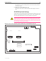
Figure9: Location of main components on the AT-AR300L(S), AT-AR300(S), and
AT-AR310(S) base CPU cards.
DB9
RJ45
CONFIG
J1
BRI 0
J2
ISDN TX
TERMINATION
RJ45
PC
ASYNCHRONOUS
PORT 0
RJ11
RJ11
VOICE 0
VOICE 1
HUB
MDX
ETHERNET 0
ISDN RX TERMINATION
M1
M2
REV
S/N
MAC CARD SLOT
WARNING:
LITHIUM BATTERY
DO NOT DISPOSE IN FIRE
BOOT EPROM
System
Run
Power
LED
LED
LED
LED
LED
LED
LED
LED
B1 Active
LED
ISDN
B2
LED
LAN
Link Txd Coll Rxd
300CPU
Table 11: Functions of the jumpers on the AT-AR300L(S), AT-AR300(S), and
AT-AR310(S) base CPU cards.
C613-03058-00 REV A
Jumper
Function
Factory Default
J1
BRI Tx termination.
Not installed (no termination).
J2
BRI Rx termination
Not installed (no termination).
28
AR Router
Figure10: Location of main components on the AT-AR320, AT-AR320, and AT-AR330
base CPU cards.
AMPLIMITE 50 WAY
SYNCHRONOUS 0
CONFIG
HUB
RJ45
ASYNCHRONOUS
PORTS 0 & 1
MDX
ETHERNET 0
ETHERNET 1
S/N
REV
SYNCHRONOUS 0 CONNECTOR
DB9
RJ45
PC
MAC CARD SLOT
WARNING:
LITHIUM BATTERY
DO NOT DISPOSE IN FIRE
BOOT EPROM
LAN
Power
LED
LED
Run
LED
Link 0
LED
System
LED
Data 0
LED
LED
Link 1
LED
LED
Data 1
LED
WAN
Rxd Txd Active
330CPU
C613-03058-00 REV A
Hardware Reference
29
Figure11: Location of main components on the AT-AR350 base CPU card.
AMPLIMITE 50 WAY
SYNCHRONOUS 0
DB9
RJ45
PC
CONFIG
HUB
ASYNCHRONOUS
PORTS 0 & 1
MDX
SYNCHRONOUS 0 CONNECTOR
ETHERNET 0
MAC CARD SLOT
WARNING:
LITHIUM BATTERY
DO NOT DISPOSE IN FIRE
S/N
BOOT EPROM
System
Run
Power
LED
LED
LED
LED
LED
LED
LED
LED
WAN
Rxd Txd Active
LED
LAN
Link Txd Coll Rxd
LED
REV
350CPU
C613-03058-00 REV A
30
AR Router
Figure12: Location of main components on the AT-AR370(S) base CPU card.
AMPLIMITE 50 WAY
SYNCHRONOUS 0
CONFIG
DB9
RJ45
PC
HUB
MDX
SYNCHRONOUS 0 CONNECTOR
RJ45
RJ45
ISDN
S/T BUS
ISDN
BRI 0
ASYNCHRONOUS
PORTS 0 & 1
ETHERNET 0
MAC CARD SLOT
REV
S/N
BOOT EPROM
System
Run
Power
LED
LED
LED
LED
LED
LED
LED
LED
WAN
Syn ISDN Active
LED
LAN
Link Txd Coll Rxd
LED
WARNING:
LITHIUM BATTERY
DO NOT DISPOSE IN FIRE
370SCPU
Table 12: Functions of the jumpers on the AT-AR370(S) base CPU cards .
Jumper
Function
Factory Default
J1
BRI Tx termination
Not installed (no termination).
J2
BRI Rx termination
Not installed (no termination).
C613-03058-00 REV A
Hardware Reference
31
Figure13: Location of main components on the AT-AR370(U) base CPU card.
CONFIG
HUB
RJ45
ASYNCHRONOUS
PORTS 0 & 1
MDX
ISDN
BRI 0
ETHERNET 0
S/N
SYNCHRONOUS 0 CONNECTOR
DB9
RJ45
PC
REV
AMPLIMITE 50 WAY
SYNCHRONOUS 0
J1 (NT MODE)
MAC CARD SLOT
BOOT EPROM
System
Run
Power
LED
LED
LED
LED
LED
LED
LED
LED
WAN
Syn ISDN Active
LED
LAN
Link Txd Coll Rxd
LED
WARNING:
LITHIUM BATTERY
DO NOT DISPOSE IN FIRE
370UCPU
Table 13: Functions of the jumpers on the AT-AR370(U) base CPU card .
C613-03058-00 REV A
Jumper
Function
Factory Default
J1
Selects NT mode (installed) or TE
mode (not installed).
Not installed (TE mode).
32
AR Router
RJ45
LED
Figure14: Location of main components on the AT-AR390 and AT-AR395 base CPU
cards.
120Ω
J2 J3
120Ω
75Ω
J4
TX
J5
RX
DB9
RJ45
PC
HUB
MDX
G.703/PRI
ISDN 0
ETHERNET 0
ASYNCHRONOUS
PORTS 0 & 1
CONFIG
S/N
REV
GND CAP
J1
(TE/NT MODE)
MAC CARD SLOT
BOOT EPROM
System
Run
Power
LED
LED
LED
LED
LED
LED
LED
LED
WAN
Syn ISDN Active
LED
LAN
Link Txd Coll Rxd
LED
WARNING:
LITHIUM BATTERY
DO NOT DISPOSE IN FIRE
390CPU
Table 14: Functions of the jumpers on the AT-AR390, and AT-AR395 base CPU
cards.
Jumper
Function
Factory Default
J1
Selects NT mode (installed) or TE mode
(not installed).
Not installed (TE mode)
J2
PRI Tx Termination (120Ω or 75Ω)
75Ω
J3
PRI Rx Termination (120Ω or 75Ω)
75Ω
J4
Coax Tx grounding: CAP (grounded via
100nF capacitor) or GND (grounded).
GND
J5
Coax Rx grounding: CAP (grounded via
100nF capacitor) or GND (grounded)
CAP
Analogue Voice Ports
The AT-AR300(S) and AT-AR310(S) have two and four analogue voice ports,
respectively. The analogue voice ports provide full PABX functionality,
including the ability to transfer calls from one port to another. Each analogue
voice port can be individually configured to meet specific requirements,
including fully programmable ringing tones.
C613-03058-00 REV A
Hardware Reference
33
For a complete description of the analogue voice port features and the
commands available to configure the PABX services, see the Software
Reference for your router.
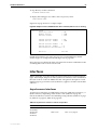
LAN Ports
All models in the AR300 Series, except the AT-AR330, have a single Ethernet
10BASE-T LAN port. The AT-AR330 has two Ethernet 10BASE-T LAN ports. A
rear panel slide switch (labelled MDX) allows the user to configure the LAN
port(s) for direct connection to either a hub or a personal computer. The same
RJ-45 cable (supplied with the router) may be used in either situation.
LAN ports operate in half duplex mode and can easily be tested using a simple
external loopback plug. See “Loopback Plugs for Testing Interfaces” on page 90 for
details of how to construct a loopback plug.
Asynchronous Ports
Asynchronous ports are wired as standard DB9 connectors, and can be
connected to most PCs using a standard DB9-to-DB9 cable. An approved DB9to-DB9 cable and DB9-to-DB25 adapter are shipped with each AR300 Series
router. The connector type and maximum speed varies from model to model
(Table 15 on page 33). All standard modem control lines are provided. By
default, the asynchronous ports operate at 9600 bps, 8 data bits, 1 stop bit, no
parity, and hardware flow control.
Table 15: Asynchronous ports, connector types, and maximum speeds on AR300
Series routers.
AR300 Series
Model
Asynchronous
Ports
Connector Type
Maximum Speed
AT-AR300L(S)
1
DB9 female
19.2Kbps
AT-AR300(S)
1
DB9 female
19.2Kbps
AT-AR310(S)
1
DB9 female
19.2Kbps
AT-AR320
2
DB9 male
115.2Kbps
AT-AR330
2
DB9 male
115.2Kbps
AT-AR350
2
DB9 male
115.2Kbps
AT-AR370(S)
2
DB9 male
115.2Kbps
AT-AR370(U)
2
DB9 male
115.2Kbps
AT-AR390
2
DB9 male
115.2Kbps
AT-AR395
2
DB9 male
115.2Kbps
G.703/PRI ISDN Ports
The G.703/PRI ISDN port provides unchannelised 2048 kbps G.703 (model
AT-AR390) or 2048 kbps Primary Rate ISDN with 30 B channels + 1 D channel
(model AT-AR395). Unbalanced 75Ω coax is supported via a pair of BNC
coaxial connectors. Balanced 120Ω twisted pair is also supported via an RJ-45
8-way connector. A push button switch on the rear panel is used to select the
required interface type for the port, and an LED on the rear panel indicates the
current selection.
The G.703/PRI ISDN port does not support “Telco supplied power” through
the twisted pair interface.
C613-03058-00 REV A
34
AR Router
Several grounding options are available for coaxial connectors. The factory
default should suit all countries, but the jumper selection in Tabl e14 on page
32 provides flexibility. Normal practice is to ground one end only of each cable,
usually the Tx cable. The other end should be left floating or connected via a
100nF capacitor.
AR400 Series Routers
AR400 Series routers are high-performance broadband routers based around
10BASE-T/100BASE-TX ports. The AR410 and AR410S include a Port Interface
Card (PIC) bay.
PIC bays add expansion flexibility by allowing the installation of PIC cards,
which are available with ISDN (PRI E1/T1, BRI S/T, or BRI U), Ethernet,
synchronous, or asynchronous ports.
There are no user-selectable jumpers or DIP switches on AR400 Series routers.
AR410 and AR410S Routers
AR410 and AR410S routers consist of a base CPU card, enclosure, and power
supply. The base CPU card supports:
■
Four 10/100 Ethernet switch ports.
■
One 10/100 Eth 0 port.
■
One asynchronous RS-232 (ASYN 0) configuration port.
■
One Port Interface Card (PIC) bay.
■
One internal MAC slot (an AT-AR011V2 MAC card is factory fitted in the
AR410S router).
The PIC bay can accommodate any of the following PICs:
•
AT-AR020 PRI E1/T1 PIC, one Primary Rate E1/T1 port.
•
AT-AR021(S) BRI-S/T PIC, one Basic Rate ISDN S/T port.
•
AT-AR021(U) BRI-U PIC, one Basic Rate ISDN U port.
•
AT-AR022 ETH PIC, one Ethernet LAN AUI/10BASE-T port.
•
AT-AR023 SYN PIC, one Synchronous port with universal 50-way
AMPLIMITE connector.
•
AT-AR024 ASYN4 PIC, four Asynchronous ports with RJ-45
connectors.
•
AT-AR026 4ETH PIC, four 10BASE-T/100 BASE-TX auto-negotiating
ports with RJ-45 connectors.
When installed in an AR410 or AR410S router and operating in V.35 mode,
synchronous PICs have full V.35 functionality, but their output voltages may not be
within the voltage range set by theV.35 specification.
Synchronous PICs installed in an AR410 or AR410S cannot be fully tested with
Syntester.
C613-03058-00 REV A
Hardware Reference
35
The MAC slot can accommodate any one of the following MACs:
•
AT-AR010 EMAC, Encryption MAC.
•
AT-AR011 ECMAC, Compression/Encryption MAC
•
AT-AR011 V2 ECMAC, Compression/Encryption MAC (factory fitted
in the AR410S router).
•
AT-AR012 CMAC, Compression MAC.
MACs should only be installed by authorised service personnel. Unauthorised
opening of the router lid may cause danger of injury from electric shock, damage
to the router, and invalidation of the product warranty.
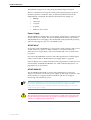
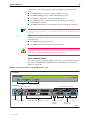
Front and rear panels of the AT-AR410 router, with a PIC installed, are shown
in Figure 15 on page 35. Apart from a different model name, the AR410S is
externally identical to the AR410.
Figure15: Front and rear panels of the AT-AR410 Series router.
AR410
PIC BAY0
STATUS
Branch Office Router
10BASE-T/100BASE-TX SWITCH PORTS
FULL DUP
FULL DUP
LINK/ACT
POWER
ENABLED
SYSTEM
ETH0
LINK/ACT
100M
100M
1
2
3
4
Tx
PIC BAY0
SYN
Rx
10BASE-T/100BASE-TX SWITCH PORTS
3X
2X
1X
4
ETH0
CONSOLE RS-232
ASYN0
X PC
POWER
= HUB
AC Power Inlet
AC Power Switch
10/100 Switch Ports
ETH 0
Console Port
PIC Bay (with optional
AT-AR023 SYN PIC)
LEDs and what they mean
Functions of AR410 and AR410S LEDs are shown in Table 16 on page 36.
Additional LEDs may be present if a PIC is installed. Functions of PIC LEDs
are described in the Port Interface Card Hardware Reference.
C613-03058-00 REV A
36
AR Router
Table 16: AR410 and AR410S System LEDs
LED
State
Function
Power
Green
The router is receiving power and the power
switch is in the ON position
System
Amber
The Router is malfunctioning
Off
Normal operation
Green
A PIC card is correctly installed and has been
detected by the router
Off
No card is installed
Green
The corresponding port is operating at fullduplex
Off
The corresponding port is operating at halfduplex
Green
A link has been established through the
corresponding port
Flashing
Data is being transmitted through the
corresponding port
Off
No link is present through the corresponding
port
Green
The corresponding port is operating at
100Mbps
Off
The corresponding port is operating at 10Mbps
Enabled
(PIC Bay 0)
Full
Link/ACT
100M
The Main System
Main features of AT-AR410 and AR410S routers are:
■
66 MHz RISC processor.
■
16 MBytes of synchronous DRAM.
■
8 MBytes of flash memory (1 MByte reserved for boot code).
■
4 x 10/100 Mbps full duplex Ethernet LAN ports.
■
1 x 10/100 Mbps full duplex Ethernet WAN port.
■
1 RS-232 asynchronous serial port (maximum speed 115200 bps).
■
1 PIC bay.
■
1 MAC slot for a MAC compression/encryption card (an AT-AR011V2
MAC card is factory fitted in the AR410S router).
■
Universal AC power supply.
C613-03058-00 REV A
Hardware Reference
37
The RS-232 asynchronous serial port (ASYN 0) can be used as a general
purpose port for terminals, printers or modems. The default communications
settings are:
•
9600 bps
•
8 data bits
•
1 stop bit
•
no parity
•
hardware flow control
Power Supply
AT-AR410 and AT-AR410S routers have a universal AC input connector and a
power switch on their rear panel. The routers require a power input of
100-240 VAC and 50–60Hz.
Some interfaces that may be installed in the router are not transformer isolated.
This means they will be referenced to the frame ground of the equipment and
may be damaged if connected to an interface on another piece of equipment
which is at a different ground potential.
AR700 Series Routers
All AR700 Series routers include PIC bays. PIC bays add expansion flexibility
by allowing the installation of PIC cards, which are available with ISDN (PRI
E1/T1, BRI S/T, or BRI U), Ethernet, synchronous, or asynchronous ports.
AR700 Series models are distinguished by the number of ports and presence or
absence of an NSM bay and PAC card slot. Where present, an NSM bay allows
the installation of an NSM, which may have additional ports or up to four PIC
bays. A PAC slot (found on the AR725, AR740, and AR745) allows the
installation of optional compression and or encryption cards, which connect to
the router through a high performance PCI bus
.
Table 17: Interface configurations for AR700 Series routers.
AR700 Series
Model
Ethernet LAN Asynchronous
Ports
Ports
PIC
Bays
(Base Unit)
NSM
Bays
MAC
Card Slot
PAC
Card Slot
AT-AR720
1
2
2
-
1
-
AT-AR725
2
2
2
-
-
1
AT-AR740
2
2
2
1
1
1
AT-AR745
2
2
2
1
-
1
C613-03058-00 REV A
38
AR Router
AR720 Router
The AT-AR720 router consists of a base CPU card, enclosure and power supply.
The base CPU card supports a single 10/100 autosensing Ethernet LAN port
and two asynchronous RS-232 ports. The chassis has two Port Interface Card
(PIC) bays, which can accommodate any combination of the following PICs:
■
AT-AR020 PRI E1/T1 PIC, one Primary Rate E1/T1 port.
■
AT-AR021(S) BRI-S/T PIC, one Basic Rate ISDN S/T port.
■
AT-AR021(U) BRI-U PIC, one Basic Rate ISDN U port.
■
AT-AR022 ETH PIC, one Ethernet LAN AUI/10BASE-T port.
■
AT-AR023 SYN PIC, one Synchronous port with universal 50-way
AMPLIMITE connector.
■
AT-AR024 ASYN4 PIC, four Asynchronous ports with R-J45 connectors.
■
AT-AR026 4ETH PIC, four 10BASE-T/100BASE-TX ports with RJ-45
connectors.
In addition, the AT-AR720 router has a dedicated MAC slot, which can
accommodate any of the following MACs:
■
AT-AR010 EMAC, Encryption MAC.
■
AT-AR011 ECMAC Compression/Encryption MAC.
■
AT-AR011 V2 ECMAC, Compression/Encryption MAC.
■
AT-AR012 CMAC, Compression MAC.
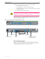
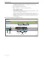
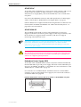
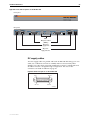
Front and Rear Panels
The AT-AR720 router’s front and rear panels (with a PIC installed in each PIC
bay) are shown in Figure on page 38.
Table 18 on page 39 lists functions of the AT-AR720’s LEDs. Additional rear
panel LEDs may be present if PICs are installed. Functions of LEDs on PICs are
described in the Port Interface Card Quick Install Guide and Port Interface Card
Hardware Reference.
C613-03058-00 REV A
Hardware Reference
39
Figure16: Front and rear panels of the AR720 Series router.
Front Panel
Model name
AR720
STATU
POWE
RUN
SYSTE
CLEA
SECURIT
Multi-Functional Remote Router
LEDs
Two PIC bays
Rear
ETHERNE
PORT
INTERFACE
ENGIN
ER
CLR
PW RUN SY
SE
100 COL
Tx
T
SYN
Rx
F
LNK
E1/T1
STATU
ACT DAT
PRI
DISCONNECT MAINS SUPPLY BEFORE
REMOVING
B
ACT
N
R
BAS
0
LEDs
Ethernet Port
1
0
BAY 1
BAY 0
POWE
Power switch Fuse Power inlet
Asynchronous ports
AR720FRP
Table 18: Functions of LEDs of the AT-AR720 router .
LED
Front panel
Function
Rear panel
ETH
These LEDs give indications about the Ethernet interfaces.
Col
Lit when a collision is detected on the Ethernet interface.
Lnk
Lit when the Ethernet interface is connected to a device (e.g., a hub),
which is generating link pulses.
Tx
Lit when data is being transmitted over the Ethernet interface.
Rx
Lit when data is being received on the Ethernet interface.
FD
Lit when the Ethernet interface is in full duplex mode.
100
Lit when the Ethernet interface is in 100 Mbps mode.
BASE
These LEDs indicate the state of the main router unit.
Power
PWR
Lit when power is supplied and the router is switched on.
Run
RUN
Lit when the internal processor is executing code. If the processor stops
for any reason (a fault condition), then the LED will not be lit.
System
SYS
This LED is not normally lit. It is used to signal various system conditions
(e.g., when the processor executes the reboot sequence). Generally it
signals a possible fault condition, but it is lit during a power-up or
operator initiated reboot, and remains lit until a release has been loaded
from flash memory.
Security
SEC
Lit when a user is logged in with SECURITY OFFICER privilege and the
router is in SECURITY MODE.
ENGINE
These LEDs give indications about a MAC (Mini Accelerator Card), which
can be installed for encryption and/or compression purposes.
ACT
Lit when a MAC card is installed in the MAC slot.
DAT
Lit when data is transferred to or from the MAC card.
ERR
Lit when there is an error in the data transmission to or from the MAC
card.
CLR
Lit when a secure router has enabled PPP interfaces or Frame Relay
circuits that are configured to send clear text.
Clear
C613-03058-00 REV A
40
AR Router
The Main System
Main features of the AT-AR720 base CPU card are:
■
50 MHz RISC processor.
■
1 MByte of EPROM.
■
16 MBytes of synchronous DRAM.
■
4 MBytes of flash memory, expandable to 8 MBytes for early models.
■
128 KBytes of battery backed SRAM.
■
A high performance 10/100 Fast Ethernet LAN port.
■
2 RS-232 asynchronous serial ports.
■
2 PIC bays.
■
A MAC compression/encryption card slot.
The Ethernet LAN port is an autosensing 10/100 full duplex interface. The
router auto-senses which interface type is in use.
The two asynchronous serial ports can be used as general purpose ports for
terminals, printers, or modems. They are effectively identical and can be
independently configured. The default communications settings are:
•
9600 bps
•
8 data bits
•
1 stop bit
•
No parity
•
Hardware flow control
Port 0 can optionally be used for diagnostics or can automatically output the
router start-up messages, by altering the internal DIP switch settings described
in “Diagnostics” on page 106.
AR725 Router
The AT-AR725 router consists of a base CPU card, enclosure and power supply.
The base CPU card supports dual 10/100 autosensing Ethernet LAN ports and
two asynchronous RS-232 ports. The chassis has two Port Interface Card (PIC)
bays, which can accommodate any combination of the following PICs:
■
AT-AR020 PRI E1/T1 PIC, one Primary Rate E1/T1 port.
■
AT-AR021(S) BRI-S/T PIC, one Basic Rate ISDN S/T port.
■
AT-AR021(U) BRI-U PIC, one Basic Rate ISDN U port.
■
AT-AR022 ETH PIC, one Ethernet LAN AUI/10BASE-T port.
■
AT-AR023 SYN PIC, one Synchronous port with universal 50-way
AMPLIMITE connector.
■
AT-AR024 ASYN4 PIC, four Asynchronous ports with R-J45 connectors.
■
AT-AR026 4ETH PIC, four 10BASE-T/100BASE-TX ports with RJ-45
connectors.
C613-03058-00 REV A
Hardware Reference
41
In addition, the AT-AR725 router has a dedicated PAC slot, which can
accommodate the following PACs:
■
AT-AR060 EPAC, Encryption PAC.
■
AT-AR061 ECPAC, Compression/Encryption PAC.
Front and Rear Panels
The AT-AR725 router’s front and rear panels (with a PIC installed in each PIC
bay) are shown in Figure 17 on page 41.
Table 19 on page 42 lists functions of the AT-AR725’s LEDs. Additional rear
panel LEDs may be present if PICs are installed. Functions of LEDs on PICs are
described in the Port Interface Card Quick Install Guide and Port Interface Card
Hardware Reference.
Figure17: Front and rear panels of the AR725 Series router.
Front Panel
AR725
STATUS
POWER
RUN
SYSTEM
COMPACT FLASH
CLEAR
SECURITY
ACTIVITY
Base LEDs
Rear Panel DC Power inlet for RPS
Link
Data
ETH
Data
Link
DISCONNECT POWER BEFORE INSTALLING/REMOVING PIC
PIC 1
AC POWER
100-240 VAC
50-60 Hz
1.0 A
Compact Flash
Two PIC bays with PICs installed
ETH
RPS DC POWER
5V/5.5A
12V/1.0A
-12V/0.1A
Enterprise Router
L /A
L /A
PIC 1
PIC 0
ACT DAT ER CLR
ENGINE
BASE
100M
Power switch
AC Power inlet
ETHERNET 1
100M
ETHERNET 0
Ethernet Ports
and LEDs
PIC 0
PWR RUN SYS SEC
PORT 1
Asynchronous
ports
Mac engine LEDs
and Base LEDs
C613-03058-00 REV A
PORT 0
725FRP
42
AR Router
Table 19: Functions of LEDs of the AT-AR725 router.
LED
Front panel
Function
Rear panel
ETH
These LEDs give indications about the Ethernet interfaces.There are two LEDs for
each Eth port.
L/A (Link/Activity)
Lit green when the Ethernet interface is connected to a device (e.g., a hub), which
is generating link pulses. Blinks yellow when data is being transmitted or received
on the Ethernet interface.
100M
Lit when the Ethernet interface is in 100 Mbps mode.
PIC0/PIC1
Lit when a PIC is inserted in either PIC bay 0 or PIC bay 1 (one LED for each PIC).
BASE
These LEDs indicate the state of the main router unit.
Power
PWR
Lit when power is supplied and the router is switched on.
Run
RUN
Lit when the internal processor is executing code. If the processor stops for any
reason (a fault condition), then the LED will not be lit.
System
SYS
This LED is not normally lit. It is used to signal various system conditions (e.g.,
when the processor executes the reboot sequence). Generally it signals a possible
fault condition, but it is lit during a power-up or operator initiated reboot, and
remains lit until a release has been loaded from flash memory.
Security
SEC
Lit when a user is logged in with SECURITY OFFICER privilege and the router is in
SECURITY MODE.
Activity
(Compact Flash)
Clear
Lit when the compact flash card is accessed.
Do not remove the compact flash card when the LED is lit.
ENGINE
These LEDs give indications about a MAC (Mini Accelerator Card), which can be
installed for encryption and/or compression purposes.
ACT
Lit when a MAC card is installed in the MAC slot.
DAT
Lit when data is transferred to or from the MAC card.
ERR
Lit when there is an error in the data transmission to or from the MAC card.
CLR
Lit when a secure router has enabled PPP interfaces or Frame Relay circuits that are
configured to send clear text.
The Main System
Main features of the AT-AR725 base CPU card are:
■
80 MHz RISC processor.
■
1 MByte of EPROM.
■
128 MBytes of synchronous DRAM (DIMM module).
■
16 MBytes of flash memory.
■
128 KBytes of battery backed SRAM.
■
2 high performance 10/100 Fast Ethernet LAN ports.
■
2 RS-232 asynchronous serial ports.
■
2 PIC bays.
■
A PAC compression/encryption card slot.
The Ethernet LAN ports are autosensing 10/100 full duplex interfaces. The
router auto-senses which interface type is in use.
C613-03058-00 REV A
Hardware Reference
43
The two asynchronous serial ports can be used as general purpose ports for
terminals, printers, or modems. They are effectively identical and can be
independently configured. The default communications settings are:
•
9600 bps
•
8 data bits
•
1 stop bit
•
No parity
•
Hardware flow control
AR740 Router
The AT-AR740 router consists of a base CPU card, enclosure, and power
supply. The base CPU card supports two 10/100 autosensing Ethernet LAN
ports and two asynchronous RS-232 ports.
AT-AR740s have a Network Service Module (NSM) bay and two Port Interface
Card (PIC) bays. The NSM bay is PCI based to provide support for a number of
higher density or higher performance interfaces.
NSMs with fixed ports are available (e.g., AT-AR041 and AT-AR042 BRI S/T
NSMs) as are NSMs with PIC bays (e.g., AT-AR040 4 PIC NSM) for flexible
expansion options. The PIC bays and the 4-PIC NSM can accommodate
combinations of the following PICs (with a maximum of two E1/T1/PRI
cards):
■
AT-AR020 PRI E1/T1 PIC, one Primary Rate E1/T1 port.
■
AT-AR021(S) BRI-S/T PIC, one Basic Rate ISDN S/T port.
■
AT-AR021(U) BRI-U PIC, one Basic Rate ISDN U port.
■
AT-AR023 SYN PIC, one Synchronous port with universal 50-way
AMPLIMITE connector.
■
AT-AR024 ASYN4 PIC, four Asynchronous ports with RJ-45 connectors.
AT-AR022 ETH PICs and AT-AR026 4ETH PICs are not recommended for use in the
NSM PIC bays, as performance of these interfaces is likely to be reduced and packet loss
may occur.
AT-AR740 routers have dedicated MAC and PAC slots. The MAC slot can
accommodate any one of the following MACs:
■
AT-AR010 EMAC, Encryption MAC card.
■
AT-AR011 ECMAC, Compression/Encryption MAC card.
■
AT-AR011 V2 ECMAC, Compression/Encryption MAC card.
■
AT-AR012 CMAC, Compression MAC card.
MACs should only be installed by authorised service personnel. Unauthorised
opening of the router lid may cause danger of injury from electric shock, damage
to the router, and invalidation of the product warranty.
C613-03058-00 REV A
44
AR Router
PAC slots can accommodate the following PACs:
■
AT-AR060 EPAC, Encryption PAC.
■
AT-AR061 ECPAC, Compression/Encryption PAC.
PACs should only be installed by authorised service personnel. Unauthorised
opening of the router lid may cause danger of injury from electric shock, damage
to the router, and invalidation of the product warranty.
Front and Rear Panels
Front and rear panels of the AT-AR740 router with a PIC installed in each PIC
bay, and an AT-AR040 4-PIC NSM installed in the NSM bay, are shown in
Figure 18 on page 44.
Figure18: Front and rear panels of the AT-AR740 Series router.
Front Panel
STATUS
Modular Branch Office Router
POWER
RUN
SYSTEM
CLEAR
SECURITY
Base LEDs
Rear Panel DC Power inlet for RPS
ETH
2
PIC 1
AC Power
100-240 VAC
50-60 Hz
1.0 A
Tx
SYN
Tx
SYN
1
NSM 0
DISCONNECT POWER BEFORE INSTALLING/REMOVING PIC
Swap
LNK
/ACT
LNK
/ACT
Rx
ENGINE
Hot
Swap
BASE
In Use
100
100
Ethernet 1
Power switch
AC Power inlet
NSM Bay with AT-AR040 4 PIC NSM and PICs installed
PIC 0
ACT DAT ERR CLR
0
Rx
Link
Link
Data
0
Data
3
ASYN
0
ASYN
3
3
ETH
RPS
Power
Two PIC bays with PICs installed
PWR RUN SYS SEC
Ethernet 0
Ethernet Ports
and LEDs
NSM Hot
Swap button
and LEDs
Port 1
Port 0
Asynchronous
ports
Base LEDSs and
MAC engine LEDs
740frac
LEDs and what they mean
Functions of the AR740’s LEDs are shown in Table 20 on page 44. Additional
rear panel LEDs may be present if a PIC or NSM is installed. Functions of PIC
and NSM LEDs are described in their respective Hardware References.
Table 20: Functions of AT-AR740 router LE D s .
LED
Front panel
Function
Rear panel
ETH
These LEDs give indications about the Ethernet interfaces.
LNK/ACT
Lit green when the Ethernet interface is connected to a device (e.g., a hub) which is
generating link pulses. Lit yellow indicates transmission or reception activity.
100M
Lit when the Ethernet interface is in 100 Mbps mode.
BASE
These LEDs indicate the state of the main router unit.
C613-03058-00 REV A
Hardware Reference
45
Table 20: Functions of AT-AR740 router LEDs. (Continued)
LED
Function
Power
PWR
Lit when power is supplied and the router is switched on.
Run
RUN
Lit when the internal processor is executing code. If the processor stops for any reason
(a fault condition), then the LED will not be lit.
System
SYS
Lit when the router or management software is malfunctioning. Flashes to indicate fan,
PSU, and RPS faults.
1 Flash: A router fan has failed.
2 Flashes: If an RPS is connected and RPS monitoring is enabled, an RPS fan has failed.
3 Flashes: If an RPS is connected, the router’s PSU (Power Supply Unit) has failed.
4 Flashes: If RPS monitoring is enabled, the RPS PSU has failed.
5 Flashes: If RPS monitoring is enabled, an RPS is not connected or is not operational
Security
Clear
SEC
Lit when a user is logged in with SECURITY OFFICER privilege and the router is in
SECURITY MODE.
ENGINE
These LEDs give indications about a MAC card, which can be installed for encryption
and/or compression purposes.
ACT
Lit when a MAC card is installed in the MAC slot.
DAT
Lit when data is transferred to or from the MAC card.
ERR
Lit when there is an error in the data transmission to or from the MAC card.
CLR
Lit when a secure router has enabled PPP interfaces or Frame Relay circuits that are
configured to send clear text.
NSM
These LEDs give indications about an NSM installed in the router.
Swap
Lit when the NSM and its PICs are powered down and can be hot swapped. Only lights
if the Hot Swap button has been pressed and the software release supports hot
swapping1.
In Use
Lit when an NSM is correctly installed. If the software release supports hot swapping,
it indicates that the NSM and its PICs are powered up and may not be swapped.
1. Hot swapping is supported by Software Release 2.3.1 or later. AT-AR021 (S) BRI-S/T, AT-AR021 (U) BRI-U, AT-AR022 ETH, AT-AR023 SYN,
and AT-AR026 4ETH PICs can be hot swapped.
The AT-AR740 router automatically monitors its own power supply and fan,
and has the option of a redundant power supply. If a redundant power supply
(RPS) is attached, the AT-AR740 software can detect the presence of the RPS
and the state of its output voltages and fan. RPS monitoring, turned off by
default, can be turned on or off using the command:
SET SYSTEM RPSMONITOR={ON|OFF}
The SHOW SYSTEM command displays the state of the main power supply
and fan, and whether or not the RPS is being monitored. If RPS monitoring is
enabled, it also shows whether an RPS is connected, and the state of its output
voltage and fan.
When a fault occurs in the main power supply or fan, system LEDs on the
AT-AR740’s front and back panels are flashed in a pattern that identifies the
fault (Table 20 on page 44). If RPS monitoring is enabled, the system LEDs also
flash to indicate failures in the RPS connection, power supply or fan. Multiple
faults are indicated by cycling through each error code.
C613-03058-00 REV A
46
AR Router
The Main System
Main features of the AT-AR740 base CPU card are:
■
80 MHz RISC processor.
■
1 MByte of EPROM.
■
16 MBytes of synchronous DRAM.
■
6 MBytes of flash memory.
■
128 KBytes of battery backed SRAM.
■
2 x 10/100 Mbps autosensing Ethernet LAN ports.
■
2 RS-232 asynchronous serial ports.
■
2 PIC bays.
■
1 hot swappable Network Service Module (NSM) bay.
■
1 MAC slot for a MAC compression/encryption card.
■
1 PAC slot for PAC compression and/or encryption cards.
■
Redundant power supply (RPS) and -48V DC power supply options.
Figure 19 on page 46 shows the location of the main components on the ATAR740 base unit. There are no user-selectable jumpers or DIP switches.
Clr Err D Act
Sec Sys Run Pwr
PORT 1
STATUS LEDs
ETHERNET 0
LNK/ Swap
ACT In
100 Use
Hot
Swap
Button
ETHERNET 1
SLIDE-IN BAY 0
SLIDE-IN BAY 1
PIC BAY 1
BOOT EPROM 0
PIC BAY 0
BOOT EPROM 1
PORT 0
LNK/
ACT
100
LED
RJ45
LED
LED
LED
LED
RJ45
LED
LED
Figure19: Location of main components on the AT-AR740 base CPU card.
NSM BAY
MAC CARD SLOT
NSM CONNECTOR
CLEAR
SECURITY
-12V
0V
0V
+5V
+5V
+12V
THREAD MOUNTS FOR PAC PILLARS
LED
LED
LED
LED
SYSTEM
LED
RUN
POWER
PAC SLOT
PAC SLOT
LITHIUM BATTERY
DO NOT
DISPOSE IN FIRE
-12V
0V
0V
0V
+5V
+5V
+12V
740CPU
C613-03058-00 REV A
Hardware Reference
47
The Ethernet LAN ports are autosensing 10/100 full duplex interfaces.
The two asynchronous serial ports can be used as general purpose ports for
terminals, printers or modems. They are effectively identical and can be
independently configured. The default communications settings are:
•
9600 bps
•
8 data bits
•
1 stop bit
•
no parity
•
hardware flow control.
Power Supply
The AT-AR740 is available in two power supply configurations: a universal AC
model and a 48V DC model. The AC model includes an inlet for the AT-RPS
740 (Redundant Power Supply). The AT-RPS 740 can be purchased separately,
and each unit supports up to two AT-AR740 routers.
AT-AR740 AC
AC models of the AT-AR740 have a universal AC input connector and a power
switch on their rear panels. A DB25 connector for an optional external
Redundant Power Supply (RPS), such as the AT-RPS 740, is also located on the
rear panel.
Pin outs for the DB25 RPS connector, and cable specifications for RPS supply
cables, can be found in “Redundant Power Supply (RPS)” on page 45.
Software Release 2.0 or higher includes monitoring functions for the PSU and
fan in both the AT-AR740 and the RPS. See “LEDs and what they mean” on
page 40, for more information.
AT-AR740-80 DC
The AT-AR740-80, designed for use by telecommunication carrier sites,
supports connection to a 48V DC power supply (in the range 39-59V DC). The
DC model does not support an RPS connection, and does not support
monitoring of the main PSU or fan.
Instructions outlining how to connect an AT-AR740-80 to a DC power supply can be
found in the AR700 Series Router Quick Install Guide. You should read these
instructions and your router’s Safety Information before attempting to connect the
router to a DC power supply
Some interfaces that may be installed in the router are not transformer isolated.
This means they will be referenced to the frame ground of the equipment and
may be damaged if connected to an interface on another piece of equipment
which is at a different ground potential.
C613-03058-00 REV A
48
AR Router
Redundant Power Supply (RPS)
AC models of the AT-AR740 can be used in conjunction with the AT-RPS 740.
Each AT-RPS 740 can provide power supply and mains circuit redundancy for
up to two AT-AR740s. For more information on the AT-RPS 740, see “AT-RPS
740” on page 54.
For connection to an AT-RPS 740, the AT-AR740 Router has a female DB25
connector on its rear panel (Figure 20 on page 48). Pin outs for the connector
are listed in Table 21 on page 48.
Figure20: DB25 female connector pinout for an RPS on the AT-AR740 rear panel
Pin 13
Pin 25
Pin 1
Pin 14
A740db25
Table 21: DB25 RPS power connector pin out on the AT-AR74 0 .
Pin
Function
Direction
1, 25
Keying
-
2, 14
+12V
input
3-5, 15-17
+5V
input
6-8, 18-20
0V
input
9
-12V
input
10
VCC
output
11
Main PSU error
output
12
Main fan error
output
13
RPS disconnected
input
21
Sense 0V
output
22
Sense +5V
output
23
RPS PSU error
output
24
RPS fan error
input
AR745 Router
The AT-AR745 router consists of a base CPU card, enclosure, and power
supply. The base CPU card supports two 10/100 autosensing Ethernet LAN
ports and two asynchronous RS-232 ports.
AT-AR745s have a Network Service Module (NSM) bay and two Port Interface
Card (PIC) bays. The NSM bay is PCI based to provide support for a number of
higher density or higher performance interfaces.
NSMs with fixed ports are available (e.g., AT-AR041 and AT-AR042 BRI S/T
NSMs) as are NSMs with PIC bays (e.g., AT-AR040 4 PIC NSM) for flexible
expansion options. The PIC bays and the 4-PIC NSM can accommodate
C613-03058-00 REV A
Hardware Reference
49
combinations of the following PICs (with a maximum of two E1/T1/PRI
cards):
■
AT-AR020 PRI E1/T1 PIC, one Primary Rate E1/T1 port.
■
AT-AR021(S) BRI-S/T PIC, one Basic Rate ISDN S/T port.
■
AT-AR021(U) BRI-U PIC, one Basic Rate ISDN U port.
■
AT-AR023 SYN PIC, one Synchronous port with universal 50-way
AMPLIMITE connector.
■
AT-AR024 ASYN4 PIC, four Asynchronous ports with RJ-45 connectors.
AT-AR022 ETH PICs and AT-AR026 4ETH PICs are not recommended for use in the
NSM PIC bays, as performance of these interfaces is likely to be reduced and packet loss
may occur.
AT-AR745 routers have a dedicated PAC slot. PAC slots can accommodate the
following PACs:
■
AT-AR060 EPAC, Encryption PAC.
■
AT-AR061 ECPAC, Compression/Encryption PAC.
PACs should only be installed by authorised service personnel. Unauthorised
opening of the router lid may cause danger of injury from electric shock, damage
to the router, and invalidation of the product warranty.
Front and Rear Panels
Front and rear panels of the AT-AR745 router with a PIC installed in each PIC
bay, and an AT-AR040 4-PIC NSM installed in the NSM bay, are shown in
Figure 21 on page 49.
Figure21: Front and rear panels of the AT-AR745 Series router.
Front Panel
AR745
STATUS
RUN
SYSTEM
CLEAR
SECURITY
ACTIVITY
LEDs
Compact Flash
Rear Panel DC Power inlet for RPS
Data
0
Link
3
Data
ETH
2
ETH
0
ASYN
3
3
ASYN
RPS DC POWER
5V/5.5A
12V/1.0A
-12V/0.1A
Two PIC bays with PICs installed
DISCONNECT POWER BEFORE INSTALLING/REMOVING PIC
PIC 1
AC POWER
100-240 VAC
50-60 Hz
1.0 A
Tx
SYN
Tx
SYN
1
NSM 0
SWAP
Rx
L /A
PIC 1
NSM Bay with AT-AR040 4-PIC NSM and PICs installed
PIC 0
ACT DAT ER CLR
ENGINE
HOT
SWAP
BASE
IN
Power switch
AC Power inlet
L /A
0
Rx
Link
POWER
Modular Enterprise Router
COMPACT FLASH
100M
ETHERNET 1
100M
ETHERNET 0
Ethernet Ports
and LEDs
NSM Hot
Swap button
and LEDs
PIC 0
PWR RUN SYS SEC
PORT 1
PORT 0
Asynchronous
ports
MAC engine
and Base LEDs
745FRP
C613-03058-00 REV A
50
AR Router
LEDs and what they mean
Functions of the AR745’s LEDs are shown in Table 22 on page 50. Additional
rear panel LEDs may be present if a PIC or NSM is installed. Functions of PIC
and NSM LEDs are described in their respective Hardware References.
Table 22: Functions of AT-AR745 router LE D s .
LED
Front panel
Function
Rear panel
ETH
These LEDs give indications about the Ethernet interfaces.
LNK/ACT
Lit green when the Ethernet interface is connected to a device (e.g., a hub) which is
generating link pulses. Lit yellow indicates transmission or reception activity.
100M
Lit when the Ethernet interface is in 100 Mbps mode.
PIC0/PIC1
Lit when a PIC is inserted in either PIC bay 0 or PIC bay 1 (one LED for each PIC).
BASE
These LEDs indicate the state of the main router unit.
Power
PWR
Lit when power is supplied and the router is switched on.
Run
RUN
Lit when the internal processor is executing code. If the processor stops for any reason
(a fault condition), then the LED will not be lit.
System
SYS
Lit when the router or management software is malfunctioning. Flashes to indicate fan,
PSU, and RPS faults.
1 Flash: A router fan has failed.
2 Flashes: If an RPS is connected and RPS monitoring is enabled, an RPS fan has failed.
3 Flashes: If an RPS is connected, the router’s PSU (Power Supply Unit) has failed.
4 Flashes: If RPS monitoring is enabled, the RPS PSU has failed.
5 Flashes: If RPS monitoring is enabled, an RPS is not connected or is not operational
Security
SEC
Activity
(Compact Flash)
Clear
Lit when a user is logged in with SECURITY OFFICER privilege and the router is in
SECURITY MODE.
Lit when the compact flash card is accessed.
Do not remove the compact flash card when the LED is lit.
ENGINE
These LEDs give indications about a MAC card, which can be installed for encryption
and/or compression purposes.
ACT
Lit when a MAC card is installed in the MAC slot.
DAT
Lit when data is transferred to or from the MAC card.
ERR
Lit when there is an error in the data transmission to or from the MAC card.
CLR
Lit when a secure router has enabled PPP interfaces or Frame Relay circuits that are
configured to send clear text.
NSM
These LEDs give indications about an NSM installed in the router.
Swap
Lit when the NSM and its PICs are powered down and can be hot swapped. Only lights
if the Hot Swap button has been pressed and the software release supports hot
swapping1.
In Use
Lit when an NSM is correctly installed. If the software release supports hot swapping,
it indicates that the NSM and its PICs are powered up and may not be swapped.
1. Hot swapping is supported by Software Release 2.3.1 or later. AT-AR021 (S) BRI-S/T, AT-AR021 (U) BRI-U, AT-AR022 ETH, AT-AR023 SYN,
and AT-AR026 4ETH PICs can be hot swapped.
C613-03058-00 REV A
Hardware Reference
51
The AT-AR745 router automatically monitors its own power supply and fan,
and has the option of a redundant power supply. If a redundant power supply
(RPS) is attached, the AT-AR745 software can detect the presence of the RPS
and the state of its output voltages and fan. RPS monitoring, turned off by
default, can be turned on or off using the command:
SET SYSTEM RPSMONITOR={ON|OFF}
The SHOW SYSTEM command displays the state of the main power supply
and fan, and whether or not the RPS is being monitored. If RPS monitoring is
enabled, it also shows whether an RPS is connected, and the state of its output
voltage and fan.
When a fault occurs in the main power supply or fan, system LEDs on the
AT-AR745’s front and back panels are flashed in a pattern that identifies the
fault (Table 22 on page 50). If RPS monitoring is enabled, the system LEDs also
flash to indicate failures in the RPS connection, power supply or fan. Multiple
faults are indicated by cycling through each error code.
The Main System
Main features of the AT-AR745 base CPU card are:
■
80 MHz RISC processor.
■
1 MByte of EPROM.
■
128 MBytes of synchronous DRAM (DIMM module).
■
16 MBytes of flash memory.
■
128 KBytes of battery backed SRAM.
■
2 x 10/100 Mbps autosensing Ethernet LAN ports.
■
2 RS-232 asynchronous serial ports.
■
2 PIC bays.
■
1 hot swappable Network Service Module (NSM) bay.
■
1 PAC slot for PAC compression and/or encryption cards.
■
Redundant power supply (RPS) and -48V DC power supply options.
Figure 22 on page 52 shows the location of the main components on the
AT-AR745 base CPU card. There are no user-selectable jumpers or DIP
switches.
C613-03058-00 REV A
52
AR Router
Clr Err Dat Act
Sec Sys Run Pwr
LNK/
ACT
100
PORT 0
PORT 1
STATUS LEDs
ETHERNET 0
LED
PIC1
PIC0
RJ45
LED
LED
LED
LED
LED
RJ45
LED
LED
Figure22: Location of main components on the AT-AR745 base CPU card.
LNK/ Swap
NSM
ACT In
Hot Swap
100 Use
Button
ETHERNET 1
SLIDE-IN BAY 0
SLIDE-IN BAY 1
PIC BAY 1
PIC BAY 0
LITHIUM BATTERY
DO NOT
DISPOSE IN FIRE
LOGIC
NSM BAY
NSM CONNECTOR
-12V
0V
0V
0V
+5V
+5V
+12V
CPU
LED
CLEAR
ACTIVITY
SECURITY
LED
LED
LED
LED
SYSTEM
LED
RUN
POWER
PAC SLOT
PAC SLOT
SDRAM DIMM
COMPACT FLASH
745CPU
The Ethernet LAN ports are autosensing 10/100 full duplex interfaces.
The two asynchronous serial ports can be used as general purpose ports for
terminals, printers or modems. They are effectively identical and can be
independently configured. The default communications settings are:
•
9600 bps
•
8 data bits
•
1 stop bit
•
no parity
•
hardware flow control.
Power Supply
The AT-AR745 is available in two power supply configurations: a universal AC
model and a 48V DC model. The AC model includes an inlet for the AT-RPS
745 (Redundant Power Supply). The AT-RPS 745 can be purchased separately,
and each unit supports up to two AT-AR745 routers.The AT-RPS 745 is
compatible with the AR725, AR740, and AR745 routers.
C613-03058-00 REV A
Hardware Reference
53
AT-AR745 AC
AC models of the AT-AR745 have a universal AC input connector and a power
switch on their rear panels. A DB25 connector for an optional external
Redundant Power Supply (RPS), such as the AT-RPS 745, is also located on the
rear panel.
Pin outs for the DB25 RPS connector, and cable specifications for RPS supply
cables, can be found in “Redundant Power Supply (RPS)” on page 48.
Software Release 2.0 or higher includes monitoring functions for the PSU and
fan in both the AT-AR745 and the RPS. See “LEDs and what they mean” on
page 50 for more information.
AT-AR745-80 DC
The AT-AR745-80, designed for use by telecommunication carrier sites,
supports connection to a 48V DC power supply (in the range 39-59V DC). The
DC model does not support an RPS connection, and does not support
monitoring of the main PSU or fan.
Instructions outlining how to connect an AT-AR745-80 to a DC power supply can be
found in the AR700 Series Router Quick Install Guide. You should read these
instructions and your router’s Safety Information before attempting to connect the
router to a DC power supply
Some interfaces that may be installed in the router are not transformer isolated.
This means they will be referenced to the frame ground of the equipment and
may be damaged if connected to an interface on another piece of equipment
which is at a different ground potential.
Redundant Power Supply (RPS)
AC models of the AT-AR745 can be used in conjunction with the AT-RPS 740.
Each AT-RPS 740 can provide power supply and mains circuit redundancy for
up to two AT-AR740s, AT-AR725s, or AT-AR745s. For more information on the
AT-RPS 740, see “AT-RPS 740” on page 54.
For connection to an AT-RPS 740, the AT-AR745 router has a female DB25
connector on its rear panel (Figure 23 on page 53). Pin outs for the connector
are listed in Table 23 on page 54.
Figure23: DB25 female connector pinout for an RPS on the AT-AR745 rear panel
Pin 13
Pin 25
Pin 1
Pin 14
A740db25
C613-03058-00 REV A
54
AR Router
Table 23: DB25 RPS power connector pin out on the AT-AR74 5.
Pin
Function
Direction
1, 25
Keying
-
2, 14
+12V
input
3-5, 15-17
+5V
input
6-8, 18-20
0V
input
9
-12V
input
10
VCC
output
11
Main PSU error
output
12
Main fan error
output
13
RPS disconnected
input
21
Sense 0V
output
22
Sense +5V
output
23
RPS PSU error
output
24
RPS fan error
input
AT-RPS 740
Each AT-RPS 740 can provide power supply and mains circuit redundancy for
up to two AT-AR740 AC routers. The AT-RPS 740 cannot be used with DC
versions of the router.
Installation instructions for the AT-RPS 740 can be found in the AR740 Router
Quick Start Guide. This guide is packed with each AT-RPS 740, or can be
downloaded from www.alliedtelesyn.co.nz/documentation/
documentation.html.
Figure 24 on page 55 shows the AT-RPS 740 front and rear panels.
C613-03058-00 REV A
Hardware Reference
55
Figure24: Front and rear panels of the AT-RPS 740.
Front panel
Rear panel
AC POWER 1
AC POWER 2
RPS DC OUTPUT 1
AC Power
100-240 VAC
50-60Hz
1.5A
RPS STATUS
AC Power
On
5V/6.5A
12V/1.0A
-12V/0.2A
ROUTER STATUS
RPS Fan
Fault
Main PSU
Fault
RPS PSU
Fault
RPS DC OUTPUT 2
Main Fan
Fault
5V/6.5A
12V/1.0A
-12V/0.2A
1
2
AC Power
100-240 VAC
50-60Hz
1.5A
LEDs
DC power outlets
(DB25s)
AC power
supply inlets
AC power
supply switches
DC supply cables
Two DC supply cables are packed with each AT-RPS 740. If making your own
cable, use a cable that conforms to UL2464, and has at least twenty-three
24AWG cores. The cables will need a DB25 male connector on both ends and
should be wired in a straight-through configuration. Pin outs for the
connectors are listed in Table 24 on page 56.
Figure25: DB25 male pinout on the AT-RPS 740
Pin 1
Pin 14
Pin13
Pin 25
A740rpsp
C613-03058-00 REV A
56
AR Router
Table 24: DB25 RPS power connector pin out on AT-RPS 740 .
Pin
Function
Direction
1, 25
Keying
-
2, 14
+12V
output
3-5, 15-17
+5V
output
6-8, 18-20
0V
output
9
-12V
output
10
VCC
input
11
Main PSU error
input
12
Main fan error
input
13
0V
output
21
Sense 0V
input
22
Sense +5V
input
23
RPS PSU error
input
24
RPS fan error
output
Specifications
Dimensions
•
Height = 44 mm (plus 5.5 mm if the rubber feet are used)
•
Width = 440 mm (excluding rack-mounting brackets)
•
Depth = 315 mm
•
Weight = 3.75 kg
Mounting System
•
1.5U rack mounting
Environmental Conditions
•
Operating temperature range: 0 to 40º C (32 to 104º F)
•
Storage temperature range: -25 to 70º C (-13 to 158º F)
•
Relative humidity range: 5 to 95% non-condensing
Regulatory Standards
•
EMC: CISPR22 class A, FCC class A, and VCCI class I
•
Immunity testing to EN50082 levels 2 (ESD), 3 (susceptibility), 4 (fast
transients), 5 (power surge), and 6 (RF immunity)
•
Safety: UL1950, CSA22.2, EN60950 and CE
C613-03058-00 REV A
Hardware Reference
57
LEDs
•
AC power supply
•
RPS fan fault
•
Router PSU fault
•
RPS PSU fault
•
Main (router) fan fault
AC Power Supply
•
Universal 110/240 VAC 50/60 Hz input
DC Output
•
5V/6.5A
•
12V/1.0A
•
-12V/0.2A
LEDs
LEDs on the rear panel indicate the RPS’s operational status.
Table 25: AT-RPS 740 LEDs.
LED
State
Function
Power
Green
The RPS unit is receiving AC power and the
voltage is within an acceptable range.
RPS Fan Fault
Amber
The RPS is switched OFF.
Mains power to the RPS has failed.
An RPS fan has failed.
Main PSU Fault
Off
Normal operation.
Amber
The corresponding router is switched OFF or its
PSU has failed.
Mains power to the router has failed.
The DC cable between the router and RPS is
not connected.
The RPS is supplying power to the router.
RPS PSU Fault
Off
Normal operation.
Amber
The RPS is switched OFF or its PSU has failed.
Mains power to the RPS has failed.
The DC cable between the corresponding
router and RPS is not connected.
Main Fan Fault
Off
Normal operation.
Amber
The DC cable between the corresponding
router and RPS is not connected.
A main router fan has failed.
Off
C613-03058-00 REV A
Normal operation.
58
AR Router
Mini Accelerator Cards (MACs)
Mini Accelerator Cards (MACs) provide additional processing features or
performance, but do not add extra physical interfaces to the router. A MAC can
be installed in the dedicated MAC slot (labelled Coprocessor Interface) on all
AR300 Series, AR400 Series, and AR720/AR740 routers.
MACs should only be installed by authorised service personnel. Unauthorised
opening of the router lid may cause danger of injury from electric shock, damage
to the router, and invalidation of the product warranty.
Three MACs are available:
■
AT-AR010 EMAC, Encryption MAC.
■
AT-AR011 V2 ECMAC, Encryption/Compression MAC.
■
AT-AR012 CMAC, Compression MAC.
See “Restricted Procedures” on page 94 for more information on the MAC
installation procedure.
How MACs work
MACs provide AR routers with high performance hardware-based encryption
and/or compression services. MACs have a DMA slave processor, which
operates independently of the base system. This processor is responsible for
the transfer of data between the base system and the MAC, and the control of
local high speed encryption and compression data processing devices.
This architecture allows data encoding to be performed off-line without
involving the base router processor in the process, thereby maximising MAC
performance while at the same time minimising impact on the router.
The MAC is a single card. Figure 26 on page 58 shows the layout of the board
for the AT-AR011 V2 ECMAC.
Figure26: Location of main components on the AT-AR011 V2 ECMAC.
MAC CARD CONNECTOR
CEMACCPU
C613-03058-00 REV A
Hardware Reference
59
Compression
MAC-based compression has the following features:
■
Local 32-bit processor for high speed control and data transfer.
■
Dedicated high performance 32-bit compression hardware.
■
High compression ratio Lempel-Ziv algorithm in hardware.
■
2 MBytes of history memory.
■
Support for up to 127 compression channels.
Compression and decompression operations are performed by a 32-bit data
compression coprocessor specifically designed for high-performance LempelZiv compression applications. The 2 MBytes of history memory allows up to
127 individual data links to use compression concurrently, enabling MACs to
provide compression for complicated network architectures. Figure 27 on page
59 shows typical compression ratios achieved by a MAC for a representative
set of file types.
Figure27: Typical hardware compression ratios by file type.
Compression Ratio
7
6
5
4
3
2
1
0
Font
Program Window
Text
Object
Spread C source
sheet
EPS
Bitmap
TIFF
File Type
CMPRATIO
Encryption
MAC-based encryption has the following features:
■
Local 32-bit processor for high speed control and data transfer.
■
Dedicated high performance 32-bit Data Encryption Standard (DES)
hardware.
■
Optional key access control.
■
Support for up to 127 encryption channels.
MAC DES encryption is based on a fast 32-bit device that complies with FIPS
PUB 46, ISO DEA-1 and ANSI X3.92 standards.
C613-03058-00 REV A
60
AR Router
Dual Mode
Throughput of an encrypted link can be dramatically increased by using data
compression. To support this, ECMACs support both encryption and
compression to provide a dual mode which allows combined compression and
encryption operations. So that the compression phase will have the best
opportunity at finding non-random data, compression occurs before
encryption, in the order:
compression → encryption →//→ decryption → decompression
Adding compression to an encrypted link increases line throughput. Once
compression has been carried out there is less data requiring encryption,
passing back to the base system, and transferring across the network, so less
base system bus and network link bandwidth is required for a given amount of
data. This results in the dual operation being very effective where encryption is
required.
PCI Accelerator Cards (PACs)
PCI Accelerator Cards (PACs) provide additional processing features or
performance, but do not add extra physical interfaces to the router. A PAC can
be installed in the dedicated PAC slot on AT-AR725, AT-AR740, and AT-AR745
routers.
Where a MAC and PAC are installed in the same router, only the PAC will
function.
PACs should only be installed by authorised service personnel. Unauthorised
opening of the router’s lid may cause danger of injury from electric shock,
damage to the router, and invalidation of the product warranty.
Two PACs are available:
■
AT-AR060 EPAC, Encryption PAC.
■
AT-AR061 ECPAC, Encryption/Compression PAC.
See “Restricted Procedures” on page 94 for more information on the PAC
installation procedure.
How PACs work
PACs provide AR725, AR740, and AR745 routers with high performance
hardware-based encryption and/or compression services. PACs have a DMA
slave processor, which operates independently of the base system. This
processor is responsible for the transfer of data between the base system and
the PAC, and the control of local high speed encryption and compression data
processing devices.
This architecture allows data encoding to be performed off-line without
involving the base router processor, thereby maximising PAC performance
while at the same time minimising impact on the router.
The PAC is a single card. Figure 28 on page 61 shows the layout of the board for
an AT-AR061 ECPAC.
C613-03058-00 REV A
Hardware Reference
61
Figure28: Location of main components on the AT-AR061 ECPAC card.
PAC Connector
Hole for PAC fastner
Holes for PAC fasteners
PAC
Compression
PAC-based compression has the following features:
■
Local 32-bit processor for high speed control and data transfer.
■
Dedicated high performance 32-bit compression hardware.
■
High compression ratio Lempel-Ziv algorithm in hardware.
■
2 MBytes of history memory.
■
Support for up to 127 compression channels.
Compression and decompression operations are performed by a 32-bit data
compression coprocessor specifically designed for high-performance LempelZiv compression applications. The 2 MBytes of history memory allows up to
127 individual data links to use compression concurrently, enabling PACs to
provide compression for complicated network architectures. Figure 29 on page
62 shows typical compression ratios achieved by a PAC for a representative set
of file types.
C613-03058-00 REV A
62
AR Router
Figure29: Typical hardware compression ratios by file type.
Compression Ratio
7
6
5
4
3
2
1
0
Font
Program Window
Text
Object
Spread C source
sheet
EPS
Bitmap
TIFF
File Type
CMPRATIO
Encryption
PAC-based encryption has the following features:
■
Local 32-bit processor for high speed control and data transfer.
■
Dedicated high performance 32-bit Data Encryption Standard – DES and
Triple DES (3DES) – hardware.
PAC DES and triple DES encryption are based on a fast 32-bit device that
complies with FIPS PUB 46, ISO DEA-1 and ANSI X3.92 standards.
Dual Mode
Throughput of an encrypted link can be dramatically increased by using data
compression. To support this, ECPACs support both encryption and
compression, providing a dual mode that allows combined compression and
encryption operations. So that the compression phase will have the best
opportunity at finding non-random data, compression occurs before
encryption, in the order:
compression → encryption →//→ decryption → decompression
Adding compression to an encrypted link increases line throughput. Once
compression has been carried out there is less data requiring encryption,
passing back to the base system, and transferring across the network, so less
base system bus and network link bandwidth is required for a given amount of
data. This results in the dual operation being very effective where encryption is
required.
C613-03058-00 REV A
Hardware Reference
63
Flash Memory
Flash memory is a nonvolatile reprogrammable memory storage device for
router software releases, allowing upgrades to be remotely loaded from any
WAN or LAN port. Flash memory is also used to store other types of data such
as patches, logs and configurations.
There are two types of flash — onboard flash (flash connected directly to the
router’s PCB and available on all routers), and CompactFlash (flash provided
by removable compact flash cards). AR725 and AR745 routers have a slot for
compact flash cards.
Onboard flash
AR Series routers have the following quantities of onboard flash memory:
■
AR300 routers, 2 MB of fixed, non-expandable flash
■
AR720 routers, 4 MB of fixed, non-expandable flash (early models can be
upgraded to 8 MB of flash)
■
AR740 routers, 6 MB of fixed, non-expandable flash
■
AR725 and AR745 routers, 16 MB of fixed flash (and a slot for compact
flash cards)
An AR router with 2 MB of flash memory can have at least one software release
upgrade stored at any time, while 4 MB of flash memory allows up to 3 releases
to be stored.
Testing Onboard Flash Memory
There are several ways to check that onboard flash memory is installed and
operating correctly. First, check that the router has recognised the flash
memory, using the command:
SHOW SYSTEM
to display system information (Figure 30 on page 64). The second part of the
display shows the types and sizes of memory installed in the router. If the flash
memory size is lower than expected, then the router’s boot process has not
correctly detected or recognised the flash memory’s presence. If recognition
fails, contact your authorised Allied Telesyn distributor or reseller.
If the flash is recognised, enter the command:
SHOW FLASH PHYSICAL
to display flash memory size, device type and location. A typical display is
shown in Figure 31 on page 64.
Lastly, the Flash File System (FFS) can be checked to ensure that it has
successfully formatted the flash, using the command:
SHOW FILE
If flash memory has been used in the past then it may already be formatted and
contain files. With erased or new flash memory that has been correctly
formatted, an 80 byte hidden system file is present. A typical display for an FFS
is shown in Figure 32 on page 65.
C613-03058-00 REV A
64
AR Router
Figure30: Example output from the SHOW SYSTEM command for the AT-AR720 router.
Router System Status
Time 17:10:06 Date 25-Sep-1999.
Board
ID Bay Board Name
Rev
Serial number
-------------------------------------------------------------------------------Base
62
AR720
M1-0 6845218
IC Module 40
0 AR022 PIC Eth
M2-0 6844595
IC Module 38
1 AR023 PIC Sync
M1-1 6844715
MAC
67
AR012 CMAC
M2-0 33636409
-------------------------------------------------------------------------------Memory DRAM : 16384 kB
FLASH : 4192 kB
-------------------------------------------------------------------------------SysDescription
CentreCOM AR720 version 1.8.1-00 08-Sep-1999
SysContact
Mr Squiggles
SysLocation
Laboratory, First Floor, Head Office Building
SysName
LAB
SysUpTime
250074 ( 00:41:40 )
Software Version: 1.8.1-00 08-Sep-1999
Release Version : 1.8.1-00 08-Sep-1999
Patch Installed : NONE
Territory
: europe
Help File
: help.hlp
Boot configuration file: load.cfg (exists)
Current configuration: load.cfg
Security Mode
: Disabled
Patch files
Name
Device
Size
Version
-------------------------------------------52772-02.paz
flash
94856
7.7.2-2
--------------------------------------------
Figure31: Example output from the SHOW FLASH PHYSICAL command for an
AT-AR720.
total size ............
device type ...........
devices ...............
location ..............
programming power .....
block erase time ......
total erase blocks ....
erase block size ......
erase bit state .......
page buffers ..........
size of page buffer ...
4 MBytes
28F008
8
SIMM stick and built in
off
1600 milliseconds
64
128 kBytes
1
0
0 bytes
C613-03058-00 REV A
Hardware Reference
65
Figure32: Example output from the SHOW FILE command for an AT-AR720.
dev
creator name
type
size
file date & time
address check
----------------------------------------------------------------------------flash inst
release
lic
64 15-Oct-1999 10:23:08 02723B20
flash load
52772
pat
300236 15-Oct-1999 10:11:47 02559AC4
flash load
52-181
rez
1575696 15-Oct-1999 10:21:48 025A2FD0
flash load
52-772
rez
1415624 15-Oct-1999 10:09:17 0240005C
----------------------------------------------------------------------------flash use:
files .....
3291968 bytes (4 files)
garbage ...
96 bytes
free ......
902516 bytes
total .....
4194304 bytes
-----------------------------------------------------------------------------
A complete test of flash memory may also be carried out using the router’s
built-in diagnostics. See “Diagnostics” on page 106 for more information.
The diagnostics flash memory test will erase the entire flash contents.
CompactFlash
AR725 and AR745 routers have a CompactFlash slot on their front panel.
Compact flash cards increase the flash memory available for file storage.
CompactFlash files can be manipulated using the command line interface. Any
type of data, including releases, patches, GUIs and configurations can be stored
on compact flash cards. However, release, patch, and GUI files cannot be run
directly from CompactFlash. These files must be loaded into either NVS or
onboard Flash.
Data contained on compact flash cards can be read with any compliant reader.
Do not keep sensitive data, for example keys, on compact flash cards.
CompactFlash functionality is supported by software Release 2.5.1 and later.
Three compact flash cards have been approved for use with AR725 and AR745
routers:
■
AT-CF032A-00 COMPFLASH 32MB
■
AT-CF064A-00 COMPFLASH 64MB
■
AT-CF128A-00 COMPFLASH 128MB
For the latest list of approved compact flash cards, visit
www.alliedtelesyn.co.nz/products/options.html.
C613-03058-00 REV A
66
AR Router
Installing and removing a compact flash card
Compact flash cards can be inserted into the CompactFlash slot at any time.
CLI messages are displayed when a card is inserted or removed. It takes
approximately two seconds for an inserted card to be initialised. Messages
notify the user when a card has been inserted:
Info (1106257): Compact flash card inserted.
and when the card is ready for use:
Info (1106268): Compact flash card initialisation successful.
A message notifies the user if the compact flash card is not compatible with the
router:
Info (3106300): Compact flash card initialisation
unsuccessful.
When CompactFlash is in use, the CompactFlash Activity LED on the front
panel of the router is green.
Do not remove the compact flash card when it is being written to (that is, when
the CompactFlash Activity LED is lit). Doing so will corrupt data on the file
being written.
Testing CompactFlash
To display information about the basic state of a compact flash card, including
card size, file count and serial number, insert the card and enter the command:
SHOW CFLASH
To display cluster ranges on a card, insert the card and enter:
SHOW CFLASH TEST
Figure 33 on page 66 shows a sample output.
Figure33: Output from the SHOW CFLASH TEST command, when no test is running.
Clusters available for testing
Ranges:
[42645--61944]
Number of free clusters
Number of ranges
Number of used clusters
= 19300
= 1
= 42645
To test a card, insert the card and enter:
ENABLE CFLASH TEST START=startnumber END=endnumber
where startnumber and endnumber are positive integers within a cluster range.
The endnumber must be higher than the startnumber. Cluster ranges are
displayed in the output of the SHOW CFLASH TEST command (Figure 33 on
page 66).
The test software will read the file allocation table and display a list of free
sectors. Sectors can be tested as single sectors or as a range. The test will consist
of a write/read/verify cycle.
C613-03058-00 REV A
Hardware Reference
67
To stop the test, use the command:
DISABLE CFLASH TEST
To display the testing process while a test is in process, enter:
SHOW CFLASH TEST
Figure 34 on page 67 shows a sample output.
Figure34: Output from the SHOW CFLASH TEST command, when a test is running.
Test Progress
Starting cluster
Ending cluster
Current cluster
Passed clusters number
Passed sectors number
= 700
= 1700
= 1185
= 485
= 1940
Failed clusters number = 0
Failed sectors number
= 0
Used Clusters encountered = 0
Duration................
4417 ms
If used when testing is not active, the previous command displays blank
cluster ranges on a compact flash card (Figur e33 on page 66).
Error messages are displayed when a file write fails. Failure could be due to the
card being removed or an error in the card.
Interfaces
Where applicable, all routers in the AR router family share common interface
types. For example, the pinout of the synchronous interface on the AT-AR350 is
the same as those on the AT-AR023 SYN PIC. The general description of each
interface type is given in this section, therefore, applies to all AR router models
and PICs.
Asynchronous Interfaces
Asynchronous interfaces use DB9 female connectors, DB9 male connectors, or
RJ-45 connectors, depending on the model or PIC (Table 26 on page 67).
Pinouts match those used for most building wiring schemes (Table 27 on page
68, Table 28 on page 68, Table 29 on page 69).
Table 26: Asynchronous interface connectors by model.
C613-03058-00 REV A
Router Model/Option
Connector
Pinouts
AT-AR300L(S)
AT-AR300(S)
AT-AR310(S)
AT-AR410
AT-AR410S
DB9 female
Table 27 on page 68
68
AR Router
Table 26: Asynchronous interface connectors by model. (Continued)
Router Model/Option
Connector
Pinouts
AT-AR320
AT-AR330
AT-AR350
AT-AR370(S)
AT-AR370(U)
AT-AR390
AT-AR395
DB9 male
Table 28 on page 68
AT-AR024 ASYN4 PIC
RJ-45
Table 29 on page 69
Table 27: Pinout of the DB9 female connectors on asynchronous interfaces (pins
are numbered from left to right) .
Pin
Function
Signal Direction
1
Not connected
2
TXD
Output from router
3
RXD
Input to router
4
DCD
Input to router
5
GND
6
DTR
Output from router
7
CTS
Input to router
8
RTS
Output from router
9
RING
Input to router (only available on expansion card interfaces)
Table 28: Pinout of the DB9 male connectors on asynchronous interfaces (pins are
numbered from left to right) .
Pin
Function
Signal Direction
1
DCD
Input to router
2
RXD
Input to router
3
TXD
Output from router
4
DTR
Output from router
5
GND
6
Not connected
7
RTS
Output from router
8
CTS
Input to router
9
Not connected
C613-03058-00 REV A
Hardware Reference
69
Table 29: Pinout of the RJ-45 connectors on asynchronous interfaces (pins are
numbered from left to right) .
Pin
Function
Signal Direction
1
RING
Input to router (only available on expansion card interfaces)
2
DCD
Input to router
3
DTR
Output from router
4
GND
5
RXD
Input to router
6
TXD
Output from router
7
CTS
Input to router
8
RTS
Output from router
Asynchronous interfaces follow the RS-232 standard. A range of speeds is
selectable using the SET PORT command from the Interfaces chapter of your
router’s Software Reference.
Not all signals need to be connected. In particular, both DCD and CTS are not
required unless the interface has been specifically set up to use them. See the
Terminal Server chapter of your router’s Software Reference for more details. A
typical terminal connection will only require RXD, TXD and GND, but refer to
the equipment manual for the connected device for more specific data.
If LPD-based printer ports are required, then the router may expect to ‘see’ the DTR
signal from the printer connected to the DCD pin of the router. This is used to detect
both the fact that the printer is ‘online’ and that it is ‘powered-on’. This prevents print
jobs from being sent to a disconnected printer and lost. See the Printer Server chapter of
your router’s Software Reference for more details.
Synchronous Interfaces
Synchronous interfaces use an AMPLIMITE 50-way connector wired as a
universal connector for RS-232/V.28, V.35 and X.21 interface standards in both
DTE and DCE modes. A transition cable is required to convert the
AMPLIMITE to the correct physical interface for the standard required (e.g.,
DB15 for X.21). The transition cable can be ordered from your supplier, or you
can construct your own cable.
Transition cables do more than simply change the physical connector. The
router hardware reads the cable type from the AMPLIMITE plug and enables
or disables the internal driver electronics as required. To function correctly, the
cables must be identical to the cables described in “Cables And Loopback Plugs”
on page 75.
DCE cable types reverse the direction of data lines as well as clock lines. This cable is
intended to be used when the router supplies the clock for the attached device. This is
commonly used when the router is connected to the synchronous interface of another
router or a host, without using an intermediate modem or NTU (Network Terminating
Unit). Therefore, the DCE cable must only be connected to a router interface which is
set to generate the clock. See the Interfaces chapter of your router’s Software Reference
for more information.
C613-03058-00 REV A
70
AR Router
Transition cables can be changed at any time. It is not necessary to power-down
the router.
When an RS-232 DCE transition cable is connected to a synchronous interface
configured to generate clocks, the maximum clock speed is 38400 bps. When an
X.21 DCE or V.35 DCE transition cable is connected to a synchronous interface
configured to generate clocks, the maximum clock speed is 2 Mbps.
Modems and NTUs
Modems and NTUs are used to transfer digital information over wide area
Telecom links. Strictly speaking, a modem is an analog device, while an NTU is
digital device.
Modems can be either asynchronous or synchronous. The distinction is that
synchronous modems provide a bit clock for both transmitted and received
data, while asynchronous modems don’t require a clock and rely on the
inherent framing provided by the start and stop bits. Normally, any modem
9600 bps or faster will be synchronous. The router can be connected to other
remote routers to form a wide area network (WAN), using synchronous
modems connected to the synchronous interfaces on the router’s rear panel.
WAN links faster than 9600 bps are normally provided using Network
Terminating Units (NTUs), which are always synchronous. The interface to
these devices is generally X.21 or V.35.
Good quality data grade cables should be used for all cables, particularly X.21.
This must be made from paired cable with an overall foil shield. Ideally,
metalised backshells should also be used. Poor quality cables will limit the
maximum speed or the maximum length of the cable, or both.
Ethernet Interfaces
10BASE-T Interfaces
All AR300 Series routers have at least one 10BASE-T Ethernet LAN port. The
AT-AR330 has two 10BASE-T Ethernet LAN ports. A rear panel slide switch
(labelled MDX) allows the user to configure the LAN port for a direct
connection to either a hub or personal computer. The same RJ-45 cable
(supplied with the router) may be used in either situation.
The LAN ports can easily be tested using a simple external loopback plug. See
“Cables And Loopback Plugs” on page 75 for details of how to construct a
loopback plug.
10BASE-T/100BASE-TX Interfaces
The AT-AR026 4ETH PIC has four 10BASE-T/100BASE-TX ports with RJ-45
connectors. Port characteristics such as speed, flow control, half/full duplex,
and auto-negotiation can be set by configuring links on the PIC’s PCB. See the
PIC Hardware Reference for more information. If your router has a PIC bay, the
PIC Hardware Reference is included on the Documentation and Tools CD-ROM
that shipped with your router, or it can be downloaded from
www.alliedtelesyn.co.nz/documentation/documentation.html.
C613-03058-00 REV A
Hardware Reference
71
Ethernet Dual 10BASE-T/AUI Interfaces
The AT-AR022 ETH PIC has a dual 10BASE-T/AUI Ethernet interface. Only
one Ethernet interface type can be active at any one time. The PIC auto-senses
which Ethernet interface type is in use.
The AUI interface is able to supply the required +12 Volts to attached transceivers. The
+12 Volts is fused to prevent any transceiver faults from causing problems with the
router. See the description of the appropriate router series in this Reference for the
location of the fuse. The fuse must be a 500 mA type. If the fuse fails, LEDs on any
attached transceiver will not be lit. The AUI cable should be checked for continuity
problems if the fuse blows.
Basic Rate ISDN Interfaces
Basic Rate ISDN (BRI) interfaces support two 64K B channels and one D
channel. On some routers and expansion cards the operational mode of the BRI
ISDN interface (TE or NT) is determined by jumpers mounted on the CPU or
expansion card. Other models and expansion cards—in particular those with U
interfaces—only support TE mode.
See the description of the relevant router model in this Reference for details of
the locations and names of jumpers. See the Integrated Services Digital Network
(ISDN) chapter of your router’s Software Reference for a detailed description
of the two operational modes. The router should be configured as a TE for
normal operation.
The jumpers used to determine interface termination are normally removed as
the building wiring will provide the correct termination for an ISDN TE-to-NT
circuit. When the BRI is connected in a point-to-point configuration, the
jumpers may need to be installed to terminate the line pairs with internal 100Ω
resistors.
See the description of the relevant router series (in this Reference) for details of
the locations and names of jumpers. The Integrated Services Digital Network
(ISDN) chapter of your router’s Software Reference also has additional
information. The BRI interface pin out is shown in Tabl e30 on page 71.
If you are unsure of whether to terminate the line or not, contact your ISDN service
provider or your authorised Allied Telesyn distributor or reseller.
Table 30: Pinout of the Basic Rate ISDN interface .
C613-03058-00 REV A
Pin
S/T Interface Functions
U Interface Functions
1
-
-
2
-
-
3
TX+
-
4
RX+
positive (+)
5
RX-
negative (-)
6
TX-
-
7
-
-
8
-
-
72
AR Router
Primary Rate ISDN Interfaces
Primary Rate ISDN interfaces on the AT-AR390 and AT-AR395 support
connection to either 75Ω or 120Ω networks. The 75Ω interfaces conform to the
standard BNC method of connection to 75Ω coaxial cable (Table 31 on page 72).
Since there is currently no official international standard for “pluggable”
connection to a 120Ω system, 120Ω interfaces employ the RJ-45 method of
connection used by most other manufacturers (Table 32 on page 72).
Primary Rate ISDN interfaces on the AT-AR020 PRI E1/T1 PIC and AT-AR025
PRI/G.703 PIC support connection to 120Ω networks using the RJ-45 method
of connection used by most other manufacturers (Table 32 on page 72). An
external balun is required to connect to a 75Ω network.
Table 31: Connection standard for Primary Rate ISDN BNC 75Ω connectors.
Signal
Connection
TX-/RX-
Outer conductor (i.e., shield)
TX+/RX+
Inner conductor
Table 32: Connection standard for Primary Rate ISDN RJ-45 120Ω connectors (from
left to right, with latch down, as viewed from the rear) .
Pin
Signal
1
RX+
2
RX-
3
RX ground selection from jumper
4
TX+
5
TX-
6
TX ground selection from jumper
7
Not connected
8
Not connected
Voice Ports
Voice ports on the AT-AR300(S) and AT-AR310(S) use a standard RJ11
telephone socket that provides a Tip and Ring A/B pair (Tabl e33 on page 72).
An RJ11-to-BT adaptor cable can be used to connect telephones with BT-style
plugs to RJ11 ports (Figure 52 on page 89).
Table 33: Pinout of the voice port RJ11 connectors .
Pin
Function
1
Not connected
2
Not connected
3
RING
4
TIP
5
SHUNT
6
Not connected
C613-03058-00 REV A
Hardware Reference
73
Test Facility
A Test Facility designed to test the router’s physical interfaces is built into all
AR router software. The test Facility can be thought of as a specialised interface
module like PPP or Frame Relay. Although the router can continue to operate
normally during specific tests, any interfaces being tested are dedicated to the
Test Facility. For more information on the Test Facility’s operation, see the Test
Facility chapter of your router’s Software Reference.
AR routers support a wide range of interface types, including Ethernet,
asynchronous, synchronous, Basic Rate ISDN and Primary Rate ISDN. Each
interface type (except Ethernet interfaces on the AT-AR026 PIC) can be tested
independently using the Test Facility software. Most tests, however, will also
require the use of a loopback plug. For more information on loopback plugs,
see “Loopback Plugs for Testing Interfaces” on page 90.
The Test Facility will not test AT-AR026 PICs.
The following examples show how to test specific interfaces.
Test results are displayed with the command:
SHOW TEST
which produces a display like that shown in Figure 35 on page 73.
Figure35: Example output from the SHOW TEST command.
Board
ID Bay Board Name
Rev
Serial number
---------------------------------------------------------------------------Base
62
AR720
M1-0 6845181
IC Module 38
0 AR023 PIC Sync
M1-1 5917086
IC Module 44
1 AR025 PIC E1 PRI
M1-0 6843626
MAC
68
AR011 ECMAC
P1-1 6804365
Duration
Details
Interface State
Result
Type (minutes) Data( %OK ) Control
---------------------------------------------------------------------------eth0
halted
* Active LAN
trans
< 1
BAD ( 0.0)
TP
0
ENDEC
0
MAC
0
port0
port1
complete
complete
good
good
syn0
testing
wait continuous
PRI0
halted
RS-232dte
dce
X.21 dte
dce
V.35 dte
dce
-
1000
1000
good( 99.0)
good( 99.0)
good
good
355
355
354
0
354
0
good(100.0)
good(100.0)
good(100.0)
good(100.0)
-
good
good
good .
good
-
< 1
BAD (
0.0)
-
mac0
complete good
DES
4
good(100.0)
mac1
complete good
STAC
4
good(100.0)
mac2
complete good
ALL
4
good(100.0)
----------------------------------------------------------------------------
C613-03058-00 REV A
74
AR Router
Asynchronous Interface Tests
Asynchronous interfaces require a loopback plug to be installed before the test
will operate. See “Cables And Loopback Plugs” on page 75 for details of how to
make a loopback plug. To start a test of an asynchronous interface, use the
command:
ENABLE TEST INT=PORTn
where n is the interface number. This will run the test for 4 minutes. Use the
SHOW TEST command (from the Test Facility chapter of your router’s Software
Reference), to observe the test progress.
Ethernet LAN Interface Tests
The Test Facility will not test Ethernet interfaces on AT-AR026 PICs.
A loopback plug is required to run the first part of the Ethernet LAN test. See
“Cables And Loopback Plugs” on page 75 for details of how to make a loopback
plug. To start a test of an Ethernet interface, use the command:
ENABLE TEST INT=ETHn
where n is the Ethernet interface number. This will run the test for 4 minutes.
Use the SHOW TEST command (from the Test Facility chapter of your router’s
Software Reference), to observe the test progress.
WAN Port Tests
To fully test synchronous interfaces, an external tester (available from your
authorised Allied Telesyn distributor or reseller) is required. A loopback plug
is not required to test BRI interfaces.
To start a WAN interface test, use the command:
ENABLE TEST INT=SYNn
or
ENABLE TEST INT=BRIn
where n is the WAN interface number. This will run the test for 4 minutes. Use
the SHOW TEST command (from the Test Facility chapter of your router’s
Software Reference), to observe the test progress.
If a test fails, please contact your authorised Allied Telesyn distributor or reseller.
C613-03058-00 REV A
Hardware Reference
75
Cables And Loopback Plugs
This section describes how to make cables for connecting the AR router to
networks, terminals, and printers. It also describes loopback plugs, which are
required for testing most AR router interfaces.
Transition Cables for Network Interfaces
AR router synchronous ports use AMPLIMITE 50-way connectors wired as
universal connectors to supp/rt RS-232/V.28, V.35 and X.21 interface
standards. DTE and DCE modes are supported.
A transition cable is required to convert the AMPLIMITE to the correct
physical interface for the standard required (e.g., DB15 for X.21). The transition
cable can be ordered from your authorised Allied Telesyn distributor or
reseller, or you can construct your own cable by following the wiring diagrams
in this section.
The transition cable does more than simply change the physical connector. The
router hardware ‘reads’ the cable type from the AMPLIMITE plug and enables
or disables the internal driver electronics as required. To function correctly, the
cables must be identical to the cables described in this section.
The DCE cable type reverses the direction of data lines as well as clock lines. This cable
is intended to be used when the router supplies the clock for an attached device. This is
commonly used when the router is connected to the synchronous port of another router
or a host, without using an intermediate modem or NTU (Network Terminating Unit).
Therefore, the DCE cable must only be connected to a router port that is set to generate
the clock. See the Interfaces chapter of your router’s software Reference for more
information. The AMPLIMITE connector supports both DTE and DCE modes for all
three physical standards.
Please pay particular attention to V.35 connections. The router interface is fully
compliant to V.35 but many DCE (DSU/CSU) devices are not. Because of the low signal
levels used for V.35 (500mV point-to-point), issues such as ground loops and excess
cable length become more important than with X.21. In particular, some DCE devices
connect the cable ground to chassis or safety ground. This can create an earth loop
condition through the shield wire of the V.35 interface. The symptom of this condition is
unexpectedly high received packet errors (CRC, Abort, etc.) as seen in the SHOW SYN=n
COUNT command’s output. In these cases the suggested remedy is to break the earth
loop by disconnecting (and isolating) pin A inside the M34 connector. This action does
not compromise the safety of the product in any way.
Transition cables can be changed at any time. It is not necessary to power-down
the router.
Good quality data grade cables should be used for all cables. All transition cables must
be made from paired cable with an overall foil shield. Metalised backshells must also be
used. Poor quality cables will limit the maximum speed or the maximum length of the
cable, or both.
C613-03058-00 REV A
76
AR Router
It is very important that the cables do not degrade EMC emission standards of the router
(e.g., FCC, CISPR). The cable foil shield must be connected to the AMPLIMITE
metalised backshell with a 360 degree ferrule. In addition, on specified cables, a clip-on
cable ferrite must be attached to the cable at the AMPLIMITE end, no more than 25 mm
from the rear of the backshell of the AMPLIMITE connector. Contact your authorised
Allied Telesyn distributor or reseller for a list of approved ferrites.
Table 34 on page 76 lists the wiring diagrams to follow when constructing
transition cables for each physical interface standard.
Table 34: Transition cable pin wiring diagrams.
Physical Interface Standard
Pin Wiring Diagram
RS-232 DTE
Figure 36 on page 77
RS-232 DCE
Figure 37 on page 78
V.35 DTE
Figure 38 on page 79
V.35 DCE
Figure 39 on page 80
X.21 DTE
Figure 40 on page 81
X.21 DCE
Figure 41 on page 82
C613-03058-00 REV A
Hardware Reference
77
Figure36: Pin wiring diagram for an RS-232 DTE transition cable to an AMPLIMITE
50-way connector.
D50 SCSI-2 Male
(to router)
D25 Male
(to DCE)
Connect to backshell
→
←
→
←
←
←
←
←
→
→
→
Pin 1
Cable Shield
1
Shield
TD
RD
RTS
CTS
DSR
12
2
14
3
4
2
3
4
5
6
TD
RD
RTS
CTS
DSR
(103)
(104)
(105)
(106)
(107)
SG
1
7
SG
(102)
CD
TC
RC
LL
DTR
RL
FGND
FSELA
5
10
8
16
13
15
21
22
8
15
17
18
20
21
CD
TC
RC
LL
DTR
RL
(109)
(114)
(115)
(141)
(108)
(140)
FGND
FSELB
46
47
Pin 1
Pin 25
Ferrite
Pin 26
Insulating
Sheath
Pin 50
D50 SCSI-2 Male — Pin View
Pin 13
Cable
Pin 14
Pin 25
D25 Male — Pin View
Notes:
(1) → Output from router; ← Input to router.
(2) Use shielded cable with twisted pairs, e.g. UL2789 28AWG. Twisted pairing must be
1-26, 2-27, 3-28, etc.
(3) D25 connector shells to be metallised and fully shielded 360°.
(4) Standard cable length is 2.05m ± 0.05m.
(5) Ferrite to be fitted to cable no more than 25mm from rear of D50 SCSI-2 backshell.
(6) Cable version 4.0.
A50R232T
C613-03058-00 REV A
78
AR Router
Figure37: Pin wiring diagram for an RS-232 DCE transition cable to an AMPLIMITE
50-way connector.
D50 SCSI-2 Male
(to router)
D25 Female
(to DTE)
Connect to backshell
←
→
←
→
→
Cable Shield
Insulating
Sheath
1
Shield
→
RD
TD
CTS
RTS
DTR
SG
RL
2
12
3
14
13
1
15
2
3
4
5
6
7
8
TD
RD
RTS
CTS
DSR
SG
CD
(103)
(104)
(105)
(106)
(107)
(102)
(109)
→
TCG
20
15
TC
(114)
17
RC
(115)
20
DTR
(108)
←
Pin 1
DSR
4
FGND
FSELA
21
22
Pin 13
Pin 25
Ferrite
Pin 26
Pin 50
D50 SCSI-2 Male — Pin View
Pin 1
Cable
Pin 25
Pin 14
D25 Female — Pin View
Notes:
(1) → Output from router; ← Input to router.
(2) Use shielded cable with twisted pairs, e.g. UL2789 28AWG. Twisted pairing must be
1-26, 2-27, 3-28, etc.
(3) D25 connector shells to be metallised and fully shielded 360°.
(4) Standard cable length is 2.05m ± 0.05m.
(5) Ferrite must be fitted to cable no more than 25mm from rear of D50 SCSI-2 backshell.
(6) Cable version 4.0.
A50R232C
C613-03058-00 REV A
Hardware Reference
79
Figure38: Pin wiring diagram for a V.35 DTE transition cable to an AMPLIMITE 50way connector.
D50 SCSI-2 Male
(to router)
M34 Male
(to DCE)
Connect to backshell
Insulating
Sheath
Cable Shield
A
Shield
B
SIG G
A
P
S
SDA
SDB
(103)
1
→
TD
←
TC
10
35
B
Y
AA
TCA
TCB
(114)
←
RD
2
27
B
R
T
RDA
RDB
(104)
←
RC
8
33
B
V
X
RCA
RCB
(115)
→
←
←
→
←
→
→
RTS
CTS
CD
DTR
DSR
LL
RL
14
3
5
13
4
16
15
C
D
F
H
E
L
N
RTS
CTS
DCD
DTR
DSR
LL
RL
(105)
(106)
(109)
(108)
(107)
(141)
(140)
FGND
FSELB
46
47
12
37
(−5V) 25
200R
180R
105R
180R
Network A
Network B
300R
300R
200R
Pin 1
Pin A
Pin 25
Ferrite
Pin 26
Pin 50
D50 SCSI-2 Male — Pin View
Notes:
(1) → Output from router; ← Input to router.
(2) Use shielded cable with twisted pairs,
e.g. UL2919 28AWG. Twisted pairing
must be 1-26, 2-27, 3-28, etc.
(3) M34 connector shells must be metal.
Connect braid to connector shells to
make a 360° connection.
(4) Standard cable length is
2.05m ± 0.05m.
Pin C Pin KK
Pin MM
Cable
Pin B
Pin D Pin LL
Pin NN
M34 Male — Pin View
(5) Ferrite must be fitted to cable no more
than 25mm from rear of D50 SCSI-2
backshell.
(6) Resistors are 1% tolerance.
(7) See accompanying text for information
about earth loop conditions.
(8) Cable version 2.0.
A50V35T
C613-03058-00 REV A
80
AR Router
Figure39: Pin wiring diagram for a V.35 DCE transition cable to an AMPLIMITE 50way connector.
D50 SCSI-2 Male
(to router)
M34 Female
(to DTE)
Insulating
Sheath
Cable Shield
A
Shield
1
B
SIG G
Connect to backshell
←
TD
12
37
R
T
RDA
RDB
(104)
→
TC
20
45
Y
AA
TCA
TCB
(114)
→
RD
2
27
P
S
SDA
SDB
(103)
V
X
RCA
RCB
(115)
C
H
D
E
F
RTS
DTR
CTS
DSR
DCD
(105)
(108)
(106)
(107)
(109)
←
←
→
→
→
Pin 1
CTS
DSR
RTS
DTR
RL
FGND
FSELB
FGND
FSELC
3
4
14
13
15
46
47
21
23
Pin MM
Pin 25
Ferrite
Pin 26
Pin 50
D50 SCSI-2 Male — Pin View
Pin KK Pin C
Pin A
Cable
Pin NN
Pin LL Pin D
Pin B
M34 Female — Pin View
Notes:
(1) → Output from router; ← Input to router.
(2) Use shielded cable with twisted pairs. Twisted pairing must be 1-26, 2-27,
3-28, etc.
(3) M34 connector shells must be metallised. Connect braid to connector shells to make a
360° connection.
(4) Standard cable length is 2.05m ± 0.05m.
(5) Ferrite must be fitted to cable no more than 25mm from rear of D50 SCSI-2 backshell.
(6) See accompanying text for information about earth loop conditions.
(7) Cable version 2.0.
A50V35C
C613-03058-00 REV A
Hardware Reference
81
Figure40: Pin wiring diagram for an X.21 DTE transition cable to an AMPLIMITE 50way connector.
D50 SCSI-2 Male
(to router)
D15 Male
(to DCE)
Connect to backshell
Insulating
Sheath
Cable Shield
1
Shield
1
8
Ground
→
TD
12
37
2
9
Transmit
(A)
(B)
→
RTS
14
39
3
10
Control
(A)
(B)
←
RD
2
27
4
11
Receive
(A)
(B)
←
CD
5
30
5 Indication
12
(A)
(B)
←
RXC
8
33
6
13
(A)
(B)
Pin 1
Pin 25
Pin 1
Ferrite
Pin 26
Pin 50
D50 SCSI-2 Male — Pin View
S (Clock)
Pin 8
Cable
Pin 9
Pin 15
D15 Male — Pin View
Notes:
(1) → Output from router; ← Input to router.
(2) Use shielded cable with twisted pairs, e.g. UL2789 28AWG. Twisted pairing must be
1-26, 2-27, 3-28, etc.
(3) D15 connector shells to be metallised and fully shielded 360°.
(4) Standard cable length is 2.05m ± 0.05m.
(5) Ferrite must be fitted to cable no more than 25mm from rear of D50 SCSI-2 backshell.
(6) Cable version 3.0.
A50X21T
C613-03058-00 REV A
82
AR Router
Figure41: Pin wiring diagram for an X.21 DCE transition cable to an AMPLIMITE 50way connector.
D50 SCSI-2 Male
(to router)
D15 Female
(to DTE)
Connect to backshell
Insulating
Sheath
Cable Shield
1
Shield
1
8
Ground
Receive
←
TD
12
37
4
11
←
RTS
14
39
5 Indication
12
(A)
(B)
→
RD
2
27
2
9
Transmit
(A)
(B)
→
CD
5
30
3
10
Control
(A)
(B)
→
TXC
20
45
6
13
S (Clock)
(A)
(B)
FGND
FSELC
21
23
Pin 1
Pin 25
Pin 8
Ferrite
Pin 26
Pin 50
D50 SCSI-2 Male — Pin View
(A)
(B)
Pin 1
Cable
Pin 15
Pin 9
D15 Female — Pin View
Notes:
(1) → Output from router; ← Input to router.
(2) Use shielded cable with twisted pairs. Twisted pairing must be 1-26, 2-27, 3-28, etc.
(3) D15 connector shells to be metallised and fully shielded 360°.
(4) Standard cable length is 2.05m ± 0.05m.
(5) Ferrite must be fitted to cable no more than 25mm from rear of D50 SCSI-2 backshell.
(6) Cable version 1.1.
A50X21C
C613-03058-00 REV A
Hardware Reference
83
ISDN Interface Cables
AR routers support two types of ISDN interface—Primary Rate Access and
Basic Rate Access. Figure 42 on page 83 shows how to wire a cable to connect a
Basic Rate Interface (BRI) to the ISDN network terminating equipment (NT).
Figure42: Pin wiring diagram for an ISDN Basic Rate Interface cable.
RJ45
(to switch or router)
Not
Not
→
→
←
←
Not
Not
connected
connected
TX+
TXRXRX+
connected
connected
Notes:
(1)
(2)
(3)
(4)
1
2
3
6
4
5
7
8
RJ45
(to NT)
1
2
3
6
4
5
7
8
Not connected
Not connected
RX+
→
RX→
TX←
TX+
←
Not connected
Not connected
→ Output from switch or router; ← Input to switch or router.
Use twisted pair cable, with pairs 3 and 6, and 4 and 5.
Each wire is connected to the same pins at each end.
Cable version 1.0.
BRI1NT
For Primary Rate Access there are two cabling options. Figure 43 on page 83
shows how to wire a cable to connect to the 120Ω connector of a Primary Rate
Interface (PRI). Currently there is no accepted standard for the connector at the
network termination end, so only the cable’s router end is shown. Consult you
ISDN service provider for more information.
Figure 44 on page 84 shows how to wire a cable to connect to the 75Ω connector
of a Primary Rate Interface (PRI).
Figure43: Pin wiring diagram for an ISDN Primary Rate Interface (120Ω) cable.
RJ45
(to switch or
router)
←
RX+
←
RXNot connected
→
TX+
→
TXNot connected
Not connected
Not connected
Notes:
(1)
(2)
(3)
1
2
3
4
5
6
7
8
→ Output from switch or router; ← Input to switch or router.
Use Grade 5 twisted pair cable, with pairs 1 and 2, and 4 and 5.
Cable version 1.0.
PRI120NT
C613-03058-00 REV A
84
AR Router
Figure44: Pin wiring diagram for an ISDN Primary Rate Interface (75Ω) cable.
BNC
(to router)
BNC
(to NT)
Cable Shield
→ TX
RX
Cable Shield
← RX
TX
Notes:
(1) → Output from router; ← Input to router.
(2) Use 75 ohm coaxial cable.
(3) Cable version 1.0.
PRI75NT
Terminal and Modem Cables
Table 35 on page 84 lists the wiring diagrams to follow when constructing
terminal and modem cables for various connector and port combinations.
Table 35: Terminal and modem cables.
Cable
Figure
RJ-45 (router) to DB25 female (terminal) cable
Figure 45 on page 85
DB9 female (router/DTE) to DB9 female (PC/terminal/DTE) cable
Figure 46 on page 85
DB9 male (router/DCE) to DB9 female (PC/terminal/DTE) cable
Figure 47 on page 86
DB9 female (router/DTE) to DB9 male (modem/DCE) cable
Figure 48 on page 87
DB9 male (router/DCE) to DB9 male (modem/DCE) cable
Figure 49 on page 87
RJ-45 (router) to DB25 male (modem) cable
Figure 50 on page 88
R-J45 (router) to MiniDin (Macintosh)
Figure 51 on page 88
The RING input is only available on asynchronous ports on expansion cards. It is not
available on asynchronous ports on base CPU boards.
An alternative method, for both terminal and modem cables, is to wire an R-45
patch cord (a straight pin-to-pin cable with RJ-45 connectors on both ends) and
then use an RJ-45-to-DB25 adaptor wired internally as a crossed cable. These
adaptors are available in both DB25 female and male versions from data
cabling suppliers, and are supplied with wires terminated on the RJ-45 socket
and pins on the free ends. The pins are inserted into the appropriate positions
in the DB25 shell.
C613-03058-00 REV A
Hardware Reference
85
Figure45: Pin wiring diagram for a standard RJ-45 terminal cable.
RJ45
(to switch or router)
←
→
←
→
(RXD)
(TXD)
(CTS)
(RTS)
→ (GND)
← (DTR)
← (DCD)
(RING)
Notes:
(1)
(2)
DB25
Female
1 Not connected
2
3
4
5
6 Not connected
7
8
20
22
5
6
7
8
4
3
2
1
→ Output from switch or router; ← Input to switch or router.
Cable version 1.0.
TERMINAL
Figure46: Pin wiring diagram for a standard DB9 male terminal cable.
DB9 Female
(to router/DTE)
← (DCD)
1
← (RXD)
→ (TXD)
→ (DTR)
Not Connected
(GND)
(RTS)
→ (CTS)
Not Connected
2
3
4
6
5
7
8
9
Pin 5
DB9 Female
(to PC/terminal/DTE)
4
6
3
2
1
5
8
7
9
Pin 1
Pin 5
Pin 1
Cable
Pin 9
Pin 6
DB9 Female — Pin View
Pin 9
Pin 6
DB9 Female — Pin View
Notes:
(1) → Output from router; ← Input to router.
(2) Cable version 1.0.
DB9FDB9F
C613-03058-00 REV A
86
AR Router
Figure47: Pin wiring diagram for a standard DB9 male to female terminal cable.
DB9 Male
(to router/DCE)
Not connected
→ (TXD)
← (RXD)
← (CD)
(GND)
→ (DTR)
← (CTS)
→ (RTS)
← (RING)
Pin 1
DB9 Female
(to PC/terminal/DTE)
1
2
3
4
5
6
7
8
9
1
2
3
4
5
6
7
8
9
Pin 5
Pin 5
(DCD)
(RXD)
(TXD)
(DTR)
(GND)
(DSR)
(RTS)
(CTS)
(RING)
Pin 1
Cable
Pin 6
Pin 9
Pin 9
DB9 Male Pin View
Notes:
(1)
(2)
Pin 6
DB9 Female Pin View
→ Output from router; ← Input to router.
Cable version 1.0.
DB9MDB9F
While the asynchronous port (on router models with one asynchronous port)
has a DCE female socket, the router’s internal electronics regard the port as
DTE. Signals displayed using the SHOW PORT command therefore have a
DTE perspective. The internal DTE pin roles are listed in Table 36 on page 86.
Table 36: Internal DTE pin roles
Pin
Role
2
TXD
3
RXD
4
CD
5
GND
6
DTR
7
CTS
8
RTS
C613-03058-00 REV A
Hardware Reference
87
Figure48: Pin wiring diagram for a DTE asynchronous port (DB9 male) to modem
(DCE) cable.
DB9 Female
(to router/DTE)
← (DCD)
← (RXD)
→ (TXD)
→ (DTR)
(GND)
Not connected
→ (RTS)
← (CTS)
(RING)
Pin 5
DB9 Male
(to modem/DCE)
1 (DCD)
2 (RXD)
3 (TXD)
4 (DTR)
5 (GND)
6 (DSR) Not needed
7 (RTS)
8 (CTS)
1
2
3
4
5
6
7
8
9
Pin 1
Pin 5
Pin 1
Cable
Pin 9
Pin 6
Pin 9
DB9 Female Pin View
Notes:
(1)
(2)
Pin 6
DB9 Male Pin View
→ Output from router; ← Input to router.
Cable version 1.0.
DB9MDB9F
Figure49: Pin wiring diagram for a DCE asynchronous port (DB9 female connector)
to modem cable.
DB9 Male
(to router/DCE)
Not connected
→ (TXD)
← (RXD)
← (CD)
(GND)
→ (DTR)
← (CTS)
→ (RTS)
(RING)
Pin 1
DB9 Male
(to modem/DCE)
1
2
3
4
5
6
7
8
9
3 (TXD)
2 (RXD)
1 (DCD)
5 (GND)
4 (DTR)
8 (CTS)
7 (RTS)
9
6 Not connected
Pin 5
Pin 5
Pin 1
Cable
Pin 6
Pin 9
DB9 Male Pin View
Notes:
(1)
(2)
Pin 9
Pin 6
DB9 Male Pin View
→ Output from router; ← Input to router
Cable version 1.0.
DB9MDB9F
C613-03058-00 REV A
88
AR Router
Figure50: Pin wiring diagram for a standard modem cable.
DB25
Male
RJ45
(to switch or router)
→
←
→
←
(TXD)
(RXD)
(RTS)
(CTS)
← (GND)
→ (DCD)
← (DTR)
(RING)
Notes:
(1)
(2)
6
5
8
7
4
2
3
1
1 Not connected
2
3
4
5
6 Not connected
7
8
20
22
→ Output from switch or router; ← Input to switch or router.
Cable version 1.0.
MODEM
Figure51: Pin wiring diagram for a Macintosh serial cable.
RJ45
(to switch or router)
←
→
←
→
←
→
(RING)
(DCD)
(RTS)
(RXD)
(GND)
(TXD)
(CTS)
(DTR)
Notes:
(1)
(2)
1
2
8
5
4
6
7
3
MiniDin
(to Macintosh)
1
2
3
4
5
6 Not connected
7
8
→ Output from switch or router; ← Input to switch or router.
Cable version 1.0.
MINIDIN
Transceivers and AUI Cables
There are four types of Ethernet transceiver available (Table 37 on page 89). The
10BASE-5 thick Ethernet transceiver will be remote from the router, due to the
nature of the coaxial cable, and will therefore require an AUI cable. The other
types of transceiver may be connected using an AUI cable or, if the transceiver
is small and lightweight, it may be connected directly to the AUI port on the
back of the router. If this is done, care must be taken to avoid strain on the AUI
port connector.
C613-03058-00 REV A
Hardware Reference
89
Table 37: Ethernet transceivers, media, and connector type s.
Type
Media
Connector
10BASE-2
Thin Ethernet coaxial cable
BNC
10BASE-T
Twisted pair (category 3 or better)
RJ-45
10BASE-F
Fibre optic (dual)
ST or SMA
10BASE-5
Thick Ethernet coaxial cable
Vampire TAP or “N” type
AR routers may also be connected to a network via an AUI fanout. This device
has multiple AUI ports wired as transceiver AUIs and a single standard AUI
for connection of a transceiver. This arrangement allows several Ethernet
devices to share a single transceiver. An AUI cable is required if this method is
used.
Transceivers have a switch or a jumper to enable or disable SQE (Signal Quality
Error, also known as heartbeat). AR routers do not require SQE, so it should be
disabled.
AUI cables (sometimes known as drop or transceiver cables) are available from
data cabling suppliers in a variety of lengths up to a maximum of 40 metres,
but are typically between one and five metres in length. AUI cables always
have one female and one male DB15 connector and are fitted with slide lock
retaining clips to ensure a secure attachment.
Voice Ports and Adaptor Cables
Voice ports use a standard RJ11 connector. To connect telephones with a BTstyle connector, use an RJ11-to-BT adaptor cable (Figure 52 on page 89).
Figure52: Pin wiring diagram for an RJ11 to BT adaptor cable.
RJ11 Plug
BT Socket
3
4
5
Pin 1
5
2
3
Pin 6
Cable
RJ11 — Router end view
Pin 6
Pin 1
BT Socket — Pin view
Notes:
(1) The SHUNT line (RJ11 pin 5/BT jack pin 3) is only required by some phones. If not
connected they will not ring.
RJ11BT
C613-03058-00 REV A
90
AR Router
Loopback Plugs for Testing Interfaces
Loopback plugs are used in conjunction with the Test Facility software (see the
Test Facility chapter) to test the router’s physical interfaces. The purpose of a
loopback plug is to connect the output pins on the interface to the input pins so
that any data transmitted over the interface is looped back (hence loopback
plug) and received at the same interface.
On interfaces with control signals, these are also looped back. The data
received on the interface is compared with the data transmitted to determine
whether or not the interface is functioning correctly. In order to produce a
comprehensive test report, most tests performed by the Test Facility require a
loopback plug to be inserted in the interface being tested.
Some interfaces (e.g., the synchronous ports) require a specially built external
testing device (available from your authorised Allied Telesyn distributor or
reseller) to be used in conjunction with the Test Facility.
Table 38 on page 90 lists the loopback plug wiring diagrams for each interface
type.
Table 38: Loopback plug pin wiring diagrams.
Physical Interface
Loopback Method/Pin Wiring Diagram
RJ-45 asynchronous interface
Figure 53 on page 90
DB9 Male
Figure 54 on page 91
DB9 Female
Figure 55 on page 91
Ethernet AUI interface
Figure 56 on page 91
Ethernet TP interface
Figure 57 on page 92
Basic Rate ISDN interface
Figure 60 on page 93. Most BRI interfaces are
tested without a loopback plug. See “Loopback
Plugs for BRI Interfaces” on page 92 for
instructions on how to determine if a loopback
plug is required.
Primary Rate 75Ω interface
Use a length of terminated cable as a loopback
cable on the interface.
Primary Rate 120Ω interface
Figure 58 on page 92
Figure53: RJ-45 loopback plug for testing asynchronous interfaces.
RJ45 Asynchronous Port Loopback Plug (RJ45 connector)
8 7 6 5 4 3 2 1
(RING)
(DCD)
(DTR)
(GND)
(RXD)
(TXD)
(CTS)
(RTS)
1
2
3
4
5
6
7
8
Router end view
of plug
RJ45LOOP
C613-03058-00 REV A
Hardware Reference
91
Figure54: DB9 female loopback plug for testing asynchronous ports with DB9 male
connectors.
DB9 Male Asynchronous Port Loopback Plug (DB9 female connector)
1
2
3
4
5
6
7
8
9
Pin 5
Pin 1
Pin 9
Pin 6
DB9 Female — Pin View
DB9FLOOP
Figure55: DB9 male loopback plug for testing asynchronous ports with DB9 female
connectors.
DB9 Male Asynchronous Port Loopback Plug (DB9 female connector)
1
2
3
4
5
6
7
8
9
Pin 5
Pin 9
Pin 1
Pin 6
DB9 Female — Pin View
DB9FLOOP
Figure56: Ethernet AUI loopback plug.
AUI Loopback Plug (Female D15 connector)
1
2
3
4
5
6
7
8
9
10
11
12
13
14
15
C1 = 100nF ceramic capacitor
C2 = 100nF ceramic capacitor
R1 = 1K resistor
C1
C2
R1
LED
Note
The LED and resistor provide
optional power feed checking.
They are not required for
loopback testing.
AUILOOP
C613-03058-00 REV A
92
AR Router
Figure57: Ethernet twisted pair (TP) loopback plug.
Twisted Pair (TP) Loopback Plug (RJ45 connector)
8 7 6 5 4 3 2 1
TX+
TXRX+
RX-
1
2
3
4
5
6
7
8
Switch or router
end view
Not
connected
Not
connected
•Not
TPLOOP
Figure58: Primary Rate ISDN 120Ω loopback plug.
PRI Loopback Plug (RJ45 connector)
8 7 6 5 4 3 2 1
TX+
TXRX+
RX-
1
2
3
4
5
6
7
8
Switch or router
end view
P120LOOP
Loopback Plugs for BRI Interfaces
If your router or expansion option’s BRI interface has an MC145474 or
MC145574 transceiver, a loopback plug is required before the BRI interface can
be tested. (Figure 60 on page 93 shows how to wire a suitable loopback plug.)
For all other transceiver types the test can be performed without a loopback
plug. In this case the Test Facility will still perform an internal loopback test,
but this will not test the complete physical interface. To fully test these
interfaces, an external NT mode device is required. Or, if the interface can be
configured for NT mode operation, an external TE device can be used.
To determine which type of transceiver a BRI interface uses, enter the
command:
SHOW BRI TEST
Figure 59 on page 93 shows an example of the output screen from the SHOW
BRI TEST command, with the transceiver type listed in the first line.
C613-03058-00 REV A
Hardware Reference
93
Figure59: Example output from the SHOW BRI TEST command.
Test switches for BRI instance 0 (MC145574 transceiver):
Number
Action
Status
-----------------------------------------------------1
Transceiver B1 GCI Transp Loop ........... no
2
Transceiver B2 GCI Transp Loop ........... no
3
Transceiver 2B+D GCI Transp Loop ......... no
4
Transceiver B1 GCI Non-Transp Loop ....... no
5
Transceiver B2 GCI Non-Transp Loop ....... no
6
Transceiver B1 S/T Transp Loop ........... no
7
Transceiver B2 S/T Transp Loop ........... no
8
Transceiver B1 S/T Non-Transp Loop ....... no
9
Transceiver B2 S/T Non-Transp Loop ....... no
10
Transceiver External S/T Loop ............ no
11
Transceiver 96kHz Test Tone .............. no
12
Transceiver Force Activation ...... ...... no
13
Transceiver Ignore D Channel Procs ....... no
14
Transceiver Map E Channel to GCI ......... no
15
Transceiver GCI Free Run ................. no
Figure60: Basic Rate ISDN loopback plug wiring diagram.
BRI Loopback Plug (RJ45 connector)
8 7 6 5 4 3 2 1
TX+
RX+
RXTX-
1
2
3
4
5
6
7
8
Not connected
Not connected
Router end view
of plug
Not connected
Not connected
BRILOOP
PICs and NSMs
PICs (Port Interface Cards) can be installed in some AR400 Series routers and
all AR700 Series routers. The sections describing each router model (earlier in
this Reference) list which PICs can be installed in each model of router.
Installation information for PICs can be found in the Port Interface Card Quick
Install Guide. Detailed PIC hardware information can be found in the Port
Interface Card Hardware Reference.
NSMs can be installed in AR740 and AR745 routers. Installation information
for NSMs can be found in the Network Service Module Quick Install Guide.
Detailed NSM hardware information can be found in the Network Service
Module Hardware Reference.
The PIC and NSM Quick Install Guides and Hardware References are included
on the Documentation and Tools CD-ROM bundled with all AR400 Series and
AR700 Series routers. They can also be downloaded from the AR Router
Support Site at www.alliedtelesyn.co.nz/documentation/documentation.html.
C613-03058-00 REV A
94
AR Router
Restricted Procedures
This section contains procedures that should only be performed by authorised
service personnel. Unauthorised use of procedures in this section may cause
danger of injury from electric shock, damage to the router, and invalidation of
the product warranty.
If you would like to know more about the procedures outlined in this section,
please contact your authorised Allied Telesyn distributor or reseller.
Installing a MAC
MACs can be installed in all AR300 and AR400 series routers, and AR740
routers, one MAC per router.
MACs should only be installed by authorised service personnel. Unauthorised
opening of the router lid may cause danger of injury from electric shock, damage
to the router, and invalidation of the product warranty.
Before installing a MAC:
1.
Check that you have the correct tools and equipment.
You will need a medium-sized posidrive screwdriver.
2.
Avoid injury by working in a safe environment.
The workspace should be free of hazards, and there should be sufficient
room to lay out the router, the MAC, and the tools.
3.
Unpack the MAC in an antistatic environment.
Do not attempt to install any hardware option without observing correct
antistatic procedures. Failure to do so may damage the router or hardware
option. If you are unsure what the ‘correct’ procedures are, contact your
authorised Allied Telesyn distributor or reseller.
To install a MAC:
1.
If connected, disconnect the router’s RPS power supply.
2.
Turn off the router and remove the mains power cord.
Before removing the router’s lid, the power cord and, if connected, RPS power
cord should be disconnected to reduce risk of electrical shock.
3.
Remove all interface cables.
4.
Remove the router lid.
The router lid is secured by posidrive screws. Remove the screws and lift
the lid off the chassis.
The router may need to be removed from any racking system before the lid
can be removed.
C613-03058-00 REV A
Hardware Reference
95
5.
Insert the MAC.
Position the MAC in the MAC slot on the router base card, making sure
that the support pillars located on the router base card are aligned with the
holes provided on the MAC. This ensures that the connector on the MAC is
correctly aligned with the slot on the router base card.
Press the connector firmly into place. Secure the MAC using the fasteners
supplied.
6.
Replace the router lid and the power cord.
Secure the router’s lid. If you disconnected an RPS supply or interface
cables, reconnect them now.
The MAC is now ready to test.
Testing a MAC
There are several ways to check that the MAC is installed and operating
correctly. First, check that the router has recognised the card. Turn on the router
and enter the command:
SHOW SYSTEM
to display system information (Figure 61 on page 96).
The first part of the display shows details of the cards installed in the router.
There should be at least two entries, one for the router base card and one for
the MAC. Both the serial number and the part name should be displayed.
If there is no entry for the MAC then the router’s boot process has not correctly
detected the MAC’s presence. The most likely cause is that the MAC is not
plugged into the slot on the base card correctly. Repeat the installation process,
paying particular attention to Step 5.
Use the SHOW SYSTEM command again, and if the display is still not correct,
contact your authorised Allied Telesyn distributor or reseller.
If you have any difficulty with the MAC at any time, contact your authorised Allied
Telesyn distributor or reseller and quote the serial numbers of both the base card and the
MAC. The serial number and revision details can be read using the SHOW SYSTEM
command. It’s a good idea to record this information for later reference.
C613-03058-00 REV A
96
AR Router
Figure61: Example output from the SHOW SYSTEM command for an AR720 router with an AT-AR011 V2 ECMAC
installed.
Router System Status
Time 06:58:43 Date 15-Jun-2001.
Board
ID Bay Board Name
Rev
Serial number
-------------------------------------------------------------------------------Base
62
AR720
M1-0 40272628
PIC
75
0 AT-AR020-00 PIC E1/T1 PRI
M1-0 42189364
MAC
155
AR011 ECMAC v2
M2-0 33636408
-------------------------------------------------------------------------------Memory DRAM : 16384 kB
FLASH : 4096 kB
-------------------------------------------------------------------------------SysDescription
CentreCOM AR720 version 2.2.2-00 18-May-2001
SysContact
SysLocation
SysName
SysDistName
SysUpTime
1482 ( 00:00:14 )
Software Version:
Release Version :
Release built
:
Patch Installed :
Territory
:
Help File
:
2.2.2-00 18-May-2001
2.2.2-00 18-May-2001
Jun 6 2001 at 00:54:54
NONE
japan
help.hlp
Boot configuration file: mike.cfg (exists)
Current configuration: mike.cfg
Security Mode
: Disabled
Patch files
Name
Device
Size
Version
-------------------------------------------52203.paz
flash
8428
2.0-1
52203pac.paz
flash
12988
2.0-1
--------------------------------------------
Next, check the MAC’s status using the command:
SHOW LOG
to display a log of MAC events. A typical display is shown in Figure 62 on page
96.
Figure62: Example output from the SHOW LOG command for an AR720 router with an AT-AR011 V2 ECMAC
card installed.
Date/Time
S Mod Type SType Message
------------------------------------------------------------------------------15 06:58:28 4 ENCO ENCO MAC
7711 Found. Initialisation started
15 06:58:28 4 ENCO ENCO MAC
7711 Initialisation Successful
15 06:58:28 7 SYS REST NORM Router startup, ver 2.2.2-00, 18-May-2001, Clock
Log: 12:52:42 on 08-Jun-2001
15 06:58:28 6 PRI PINT WARN pri<0>: interface reset
15 06:58:31 6 PRI PINT UP
pri<0>: Interface is now operational
-------------------------------------------------------------------------------
C613-03058-00 REV A
Hardware Reference
97
If any MAC tests fail, check that the MAC is correctly installed in its slot and repeat the
tests. Contact your authorised Allied Telesyn distributor or reseller if the MAC does not
operate correctly.
Once the MAC is operating, its functionality can be tested either by using the
Test Facility software, which is built into the router, or by configuring a module
to use the MAC. For more information about configuring interfaces, see the
“Compression and Encryption Services” chapter of your router’s Software
Reference.
Using the Test Facility to Verify Operation
The built-in Test Facility software is the easiest way to verify the operation of a
MAC.
See the Test Facility chapter of your router’s Software Reference for more information
about the Test Facility.
To run the Test Facility for a MAC, use the command:
ENABLE TEST INTERFACE=MAC
The test will run for 4 minutes. To view the results of the test at any time, use
the command:
SHOW TEST
Figure 63 on page 97 shows a typical output. The status of the test will be
shown in the right-hand column. For further information on the meanings of
the other figures, see the “Test Facility” chapter of your router’s Software
Reference.
Figure63: Example output from the SHOW TEST command for an AR720 router with an AT-AR011 V2 ECMAC
installed.
Board
ID Bay Board Name
Rev
Serial number
---------------------------------------------------------------------------Base
62
AR720
M1-0 40272628
PIC
75
0 AT-AR020-00 PIC E1/T1 PRI
M1-0 42189364
MAC
155
AR011 ECMAC v2
M2-0 33636408
Duration
Details
Interface State
Result
Type (minutes) Data( %OK ) Control
---------------------------------------------------------------------------eth0
no test
-
-
-
-
-
-
asyn0
asyn1
no test
no test
-
-
-
-
-
-
PRI0
no test
-
-
-
-
-
-
enco0
complete good
DES
4
good(100.0)
enco1
complete good
STAC
4
good(100.0)
----------------------------------------------------------------------------
If you are unsure about running the Test Facility, or have difficulty evaluating
the results then contact your authorised Allied Telesyn distributor or reseller.
C613-03058-00 REV A
98
AR Router
Installing a PAC
PACs can be installed in AR725, AR740, and AR745 routers, one PAC per
router.
PACs should only be installed by authorised service personnel. Unauthorised
opening of the router’s lid may cause danger of injury from electric shock,
damage to the router, and invalidation of the product warranty.
Before installing a PAC:
1.
Check that you have the correct tools and equipment.
You will need a medium-sized posidrive screwdriver.
2.
Avoid injury by working in a safe environment.
The workspace should be free of hazards, and there should be sufficient
room to lay out the router, PAC, and tools.
3.
Unpack the PAC in an antistatic environment.
Do not attempt to install any hardware without observing correct antistatic
procedures. Failure to do so may damage the router or PAC. If you are unsure
what the ‘correct’ procedures are, contact your authorised Allied Telesyn
distributor or reseller.
To install a PAC:
1.
If connected, disconnect the router’s RPS power supply.
2.
Turn off the router and remove the mains power cord.
Before removing the router’s lid, the power cord and, if connected, RPS power
cord should be disconnected to reduce risk of electrical shock.
3.
Remove all interface cables.
4.
Remove the router’s lid.
The router lid is secured by four posidrive screws, two on each side, plus
two on top of the case.
The router may need to be removed from any rack mounting system before
the lid can be removed.
5.
If not already installed, install the PAC pillars.
PAC mounting pillars are normally installed when the router is
manufactured. If the pillars aren’t installed, use the metal pillars that ship
with each PAC (not the plastic pillars).
Carefully screw the pillars into the three threaded pillar mounts on the
router’s base board. The pillars should be firm but not overtight.
Figure 64 on page 99 shows the PAC pillar mounts on an AR740 base
board.
C613-03058-00 REV A
Hardware Reference
99
Clr Err D Act
Sec Sys Run Pwr
PORT 1
STATUS LEDs
ETHERNET 0
LNK/ Swap
ACT In
100 Use
Hot
Swap
Button
ETHERNET 1
SLIDE-IN BAY 0
SLIDE-IN BAY 1
PIC BAY 1
BOOT EPROM 0
PIC BAY 0
BOOT EPROM 1
PORT 0
LNK/
ACT
100
LED
RJ45
LED
LED
LED
LED
RJ45
LED
LED
Figure64: Location of PAC slot and pillar mounts on an AR740 base board.
NSM BAY
MAC CARD SLOT
NSM CONNECTOR
-12V
0V
0V
+5V
+5V
+12V
THREAD MOUNTS FOR PAC PILLARS
CLEAR
SECURITY
LED
LED
LED
LED
SYSTEM
LED
RUN
POWER
PAC SLOT
PAC SLOT
LITHIUM BATTERY
DO NOT
DISPOSE IN FIRE
-12V
0V
0V
0V
+5V
+5V
+12V
740CPU
6.
Insert the PAC.
Position the PAC over the PAC slot on the router base card, making sure
that the support pillars located on the router base card are aligned with the
holes provided on the PAC. This ensures that the connector on the PAC is
correctly aligned with the slot on the router base card.
Press the connector firmly into place. Secure the PAC to its three pillars
using the fasteners supplied.
Figure 64 on page 99 shows the PAC slot on an AR740 base board.
7.
Replace the router’s lid and the power cord.
Secure the router’s lid. If you disconnected an RPS supply, reconnect it
now.
8.
If you disconnected interface cables to install the PAC, reconnect them.
The PAC is now ready to test.
C613-03058-00 REV A
100
AR Router
Testing a PAC
There are several ways to check that the PAC is installed and operating
correctly. First, check that the router has recognised the card. Turn on the router
and enter the command:
SHOW SYSTEM
to display system information (Figure 61 on page 96).
The first part of the display shows details of the cards installed in the router.
There should be at least two entries, one for the router base card and one for
the PAC. Both the serial number and the part name should be displayed.
If there is no entry for the PAC then the router’s boot process has not correctly
detected the PAC’s presence. The most likely cause is that the PAC is not
correctly plugged into the slot on the router’s base board. Repeat the
installation process, paying particular attention to Step 6.
Use the SHOW SYSTEM command again, and if the display is still not correct,
contact your authorised Allied Telesyn distributor or reseller.
If you have any difficulty with the PAC at any time, contact your authorised Allied
Telesyn distributor or reseller and quote the serial numbers of both the base card on the
router and the PAC. The serial numbers and revision details can be read using the
SHOW SYSTEM command. It’s a good idea to record this information for later
reference.
C613-03058-00 REV A
Hardware Reference
101
Figure65: Example output from the SHOW SYSTEM command for an AR740 router with an AT-AR061 ECPAC
installed.
Router System Status
Time 09:28:27 Date
15-Jun-2001.
Board
ID Bay Board Name
Rev
Serial number
-------------------------------------------------------------------------------Base
78
AR740
M1-15 46689862
PIC
40
0 AT-AR022-00 PIC Eth
M4-0 40239075
PIC
152
1 AT-AR026-00 PIC 10/100 Eth
P1-0 40846780
PAC
153
AR061 ECPAC
P3-16 6845158
-------------------------------------------------------------------------------Memory DRAM : 16384 kB
FLASH : 4096 kB
-------------------------------------------------------------------------------SysDescription
CentreCOM AR740 version 2.2.2-00 18-May-2001
SysContact
SysLocation
SysName
SysDistName
SysUpTime
6490 ( 00:01:04 )
Software Version:
Release Version :
Release built
:
Patch Installed :
Territory
:
Help File
:
Main PSU
RPS Monitor
2.2.2-00 18-May-2001
2.2.2-00 18-May-2001
Jun 14 2001 at 00:55:17
NONE
japan
help.hlp
: ***OFF***
: Off
Main Fan
: ***OFF***
Boot configuration file: boot.cfg (exists)
Current configuration: boot.cfg
Security Mode
: Disabled
Patch files
Name
Device
Size
Version
-------------------------------------------52202tst.paz
flash
6036
2.0-1
52203pac.paz
flash
10636
2.0-1
--------------------------------------------
Next, check the PAC’s status using the command:
SHOW LOG
to display a log of PAC events. A typical display is shown in Figur e62 on page
96.
C613-03058-00 REV A
102
AR Router
Figure66: Example output from the SHOW LOG command for an AR740 router with an AT-AR061 ECPAC card
installed.
Date/Time
S Mod Type SType Message
-------------------------------------------------------------------------15 00:05:50 4 ENCO ENCO PAC
7751 Found. Initialisation started
15 00:05:50 4 ENCO ENCO PAC
7751 Initialisation Successful
15 00:05:50 7 SYS REST NORM Router startup, ver 2.2.2-00, 18-May-2001,
Clock
Log: 00:04:40 on 15-Jun-2001
15 00:05:53 3 USER USER 00011 manager login failed on port0
15 00:05:58 3 USER USER LON
manager login on port0
15 00:05:59 3 CH
MSG
WARN No patches found
--------------------------------------------------------------------------
If any PAC tests fail, check that the PAC is correctly installed in its slot and repeat the
tests. Contact your authorised Allied Telesyn distributor or reseller if the PAC does not
operate correctly.
Once the PAC is operating, its functionality can be tested either by using the
Test Facility software, which is built into the router, or by configuring a module
to use the PAC. For more information about configuring interfaces, see the
“Compression and Encryption Services” chapter of your router’s Software
Reference.
Using the Test Facility to Verify Operation
The built-in Test Facility software is the easiest way to verify a PAC’s operation.
See the Test Facility chapter of your router’s Software Reference for more information
about the Test Facility.
To run the Test Facility for a PAC, use the command:
ENABLE TEST INTERFACE=PAC
The test will run for 4 minutes. To view the results of the test at any time, use
the command:
SHOW TEST
Figure 67 on page 103 shows a typical output. The status of the test will be
shown in the right-hand column. For further information on the meanings of
the other figures, see the “Test Facility” chapter of your router’s Software
Reference.
C613-03058-00 REV A
Hardware Reference
103
Figure67: Example output from the SHOW TEST command for an AR740 router with an AT-AR061 ECPAC
installed.
Router System Status
Time 09:28:27 Date
15-Jun-2001.
Board
ID Bay Board Name
Rev
Serial number
-------------------------------------------------------------------------------Base
78
AR740
M1-15 46689862
PIC
40
0 AT-AR022-00 PIC Eth
M4-0 40239075
PIC
152
1 AT-AR026-00 PIC 10/100 Eth
P1-0 40846780
PAC
153
AR061 ECPAC
P3-16 6845158
-------------------------------------------------------------------------------Memory DRAM : 16384 kB
FLASH : 4096 kB
-------------------------------------------------------------------------------SysDescription
CentreCOM AR740 version 2.2.2-00 18-May-2001
SysContact
SysLocation
SysName
SysDistName
SysUpTime
6490 ( 00:01:04 )
Software Version:
Release Version :
Release built
:
Patch Installed :
Territory
:
Help File
:
Main PSU
RPS Monitor
2.2.2-00 18-May-2001
2.2.2-00 18-May-2001
Jun 14 2001 at 00:55:17
NONE
japan
help.hlp
: ***OFF***
: Off
Main Fan
: ***OFF***
Boot configuration file: boot.cfg (exists)
Current configuration: boot.cfg
Security Mode
: Disabled
Patch files
Name
Device
Size
Version
-------------------------------------------52202tst.paz
flash
6036
2.0-1
52203pac.paz
flash
10636
2.0-1
--------------------------------------------
If you are unsure about running the Test Facility, or have difficulty evaluating
the results then contact your authorised Allied Telesyn distributor or reseller.
C613-03058-00 REV A
104
AR Router
Installing a Flash SIMM
Early models of AT-AR720 routers can be upgraded from the factory default
4MB of flash memory to 8MB of flash memory by installing a 4MB 80-way
Single Inline Memory Module (SIMM) stick.
SIMMs should only be installed by authorised service personnel. Unauthorised
opening of the router lid may cause danger of injury from electric shock, damage
to the router, and invalidation of the product warranty.
Before installing a flash SIMM:
1.
Check that you have the correct tools and equipment.
You will need a medium-sized posidrive screwdriver.
2.
Avoid injury by working in a safe environment.
The work space should be free of hazards, and there should be sufficient
room to lay out the router, the flash SIMM stick, and the tools.
3.
Unpack the flash SIMM stick in an antistatic environment.
Flash memory, like most electronic devices, is highly sensitive to electrostatic
damage. This can be particularly acute in the dry atmosphere of computer
rooms and offices. Before commencing work, ensure that you have an approved
antistatic wrist strap connected to an earthing point. Wear the strap at all
times during this procedure. Failure to follow the correct antistatic procedures
may result in damage to the router or the flash SIMM stick. If you have any
queries about antistatic procedures, contact your authorised Allied Telesyn
distributor or reseller.
To install a flash SIMM:
1.
Turn off the router and remove the mains and, if connected, RPS power cord.
Do not take risks with mains electricity. Although the router is fully shielded
internally, the power should always be removed to reduce the risk of electrical
shock. Always disconnect the power cord and, if connected, the RPS power cord
before attempting to remove the lid of the router.
2.
Remove the router lid.
The router lid is secured by posidrive screws. Remove the screws and lift
the lid off the chassis.
The router may need to be removed from any racking system before the lid
can be removed.
3.
Insert the new SIMM.
The SIMM stick is polarised by a notch located at one end of the stick and a
half circular notch located in the middle of the stick. When the stick is
installed correctly its socket, the half circular notch will align with a bulge
in the socket.
Insert the new stick into the SIMM socket at an angle of about 60 degrees,
ensuring it is inserted fully into the socket along its entire length. Rotate
C613-03058-00 REV A
Hardware Reference
105
the stick down onto the retaining latches and ensure the latches hold the
stick firmly in place.
4.
Replace the router lid and the power cord.
Secure the router’s lid. If you disconnected an RPS supply, reconnect it
now.
AT-AR720 Dip Switch Settings
A DIP switch is used to change functional characteristics of the base CPU card.
Figure 68 on page 105 shows the DIP switch’s location on the AT-AR720’s base
CPU card. DIP switch functions are shown in Table 39 on page 106.
All DIP switches should be left in the factory default positions unless advised
by your distributor or reseller that they need to be changed. Jumpers should
only be replaced by authorised service personnel. Unauthorised opening of the
router lid may cause danger of injury from electric shock, damage to the router,
and invalidation of the product warranty.
SLIDE-IN BAY 0
RJ45
RJ45
PORT 0
PORT 1
RJ45
Tx Col 100
Rx Lnk FD
LED
LED
LED
LED
LED
LED
LED
Figure68: Location of main components, jumpers and DIP switch on the AT-AR720 base CPU card.
Clr Err D Act
Sec Sys Run Pwr
ETHERNET 0
SLIDE-IN BAY 1
PIC SLOT
PIC SLOT
FLASH SIMM
LITHIUM BATTERY
DO NOT
DISPOSE IN FIRE
BOOT EPROM 1
MAC CARD SLOT
BOOT EPROM 0
-12V
0V
0V
0V
0V
+5V
+5V
+5V
+12V
DIP SW
CLEAR
SECURITY
S/N
LED
LED
LED
LED
SYSTEM
LED
RUN
POWER
720CPU
C613-03058-00 REV A
106
AR Router
Table 39: Functions of the DIP switch on the AT-AR720 base CPU card .
DIP Switch
Function
Default
SW1-1
Reserved (should be OFF)
OFF
SW1-2
Enable startup messages (ON=enable)
ON
SW1-3
Reserved (should be OFF)
OFF
SW1-4
Enable show cycles (ON=enable)
OFF
SW1-5
Disable data cache (ON=disable)
OFF
SW1-6
Disable instruction cache (ON=disable)
OFF
SW1-7
Enable diagnostic mode (ON=enable)
OFF
SW1-8
Reserved (should be OFF)
OFF
Diagnostics
The router software includes a set of diagnostic programs. These programs
perform basic level checks of all system components. They do not run in
conjunction with the normal operating code, and require that the system be
totally dedicated to their use. A detailed knowledge of the way your router
hardware functions is necessary if diagnostics are to be used effectively.
Diagnostic mode is only to be used by authorised service personnel.
Unauthorised use of diagnostic mode may cause the router to cease functioning,
may invalidate the product warranty, and may be a breach of the product
licence agreement.
The router will not function as a router if diagnostic mode is running.
Diagnostics will not perform checks on AT-AR026 PICs.
To enable diagnostics mode:
1.
Connect a terminal to the console port.
Connect a terminal to the console port (port 0) on the router’s rear panel,
and set the terminal communications parameters to:
2.
•
9600bps
•
8 data bits
•
1 stop bit
•
No parity
•
Hardware flow control.
Restart the router.
Restart the router, either by switching it off and on again using the power
switch on the rear panel, or by using the terminal to login and enter the
command:
RESTART REBOOT
C613-03058-00 REV A
Hardware Reference
107
3.
Enable diagnostics mode during start-up.
During the router start-up process, at the prompt:
Force EPROM download (Y)?
press [Ctrl/D] on the terminal to enter diagnostics mode. A banner page will
be displayed on the terminal (Figure 69 on page 107). This can be used to
check that the terminal is correctly connected.
Figure69: AR router diagnostics banner page.
* * * Diagnostic Mode * * *
version 06-Mar-95
Main
1.
2.
3.
4.
5.
6.
7.
P.
Menu:
Full RAM test
ROM checksum test
Battery backed RAM battery test
Battery backed RAM test
Watchdog test
Full Flash Test
Totally Erase FLASH
Go to Probe
R Enter selection ==>
To run a diagnostic program, enter the corresponding letter or number. There
are several sub-menus to cover all the different options. Table 40 on page 107
lists the keys that control the basic operation of the diagnostics.
Table 40: Basic commands for running diagnostic s .
Key
Function
Q
Quits any running tests and displays the banner page.
S
Prints a summary of test results so far.
Diagnostics are designed to be used with all models of the router, and therefore
some instances of particular tests will not be appropriate for some models. A
reasonable level of understanding of the system structure is needed to operate
diagnostics and interpret the results. Diagnostics only require the base CPU
board to be installed in the system.
To restore the router to normal operation, perform a restart by switching its
power switch (rear panel) OFF and ON.
This manual is not intended as a guide to diagnostics. Diagnostics are designed to be
run by service personnel only. For more information, contact your authorised Allied
Telesyn distributor or reseller.
Running the battery-backed RAM test, Full Flash test, or Totally Erase Flash
option will cause important system files to be deleted. These will need to be
reinstalled before the router can function normally.
C613-03058-00 REV A
108
AR Router
Replacing Boot EPROMs
AR300 Series routers have one boot EPROM and AR720/AR740 routers have
two boot EPROMs. Boot EPROMs contain bootstrap code, which loads the
main code from a software release file in flash memory. In rare circumstances
the boot EPROM(s) may need to be changed. AR725 and AR745 routers do not
have boot EPROMs.
Boot EPROMs do not need to be replaced, except in rare circumstances. Boot
EPROMs should only be replaced by authorised service personnel. Contact
your authorised Allied Telesyn distributor or reseller. Unauthorised opening of
the router lid may expose you to live components and a risk of injury from
electric shock, it may also damage the router and invalidate the product
warranty.
To change the boot EPROMs:
1.
Check that you have the correct tools and equipment available.
You will need a medium sized posidrive screwdriver and an EPROM
extraction tool (or a small flat bladed screwdriver). In addition, adequate
antistatic precautions must be observed.
EPROMs, like most electronic equipment, are highly sensitive to electrostatic
damage. This can be particularly acute in the dry atmosphere normally
associated with computer rooms and typical offices. Before commencing work,
ensure that you have used an approved antistatic wrist strap to discharge any
buildup of static electricity. Wear the strap at all times during the following
procedure.
2.
Avoid injury by working in a safe environment.
The workspace should be free of hazards, and there should be sufficient
room to lay out the router, the expansion card and the tools.
3.
Turn OFF the router and remove the mains power cord.
Do not take risks with mains electricity. Do not attempt to remove the lid of a
router unless the power cord has been removed from the router.
4.
Remove the router lid.
The router lid is secured by posidrive screws. Remove the screws and lift
the lid off the chassis.
The router may need to be removed from any racking system before the lid
can be removed.
5.
Remove any MAC card (AR300 Series only).
On AR300 Series routers, if a MAC card is installed then it must be
removed to gain access to the boot EPROM. See “Installing a MAC” on
page A-69 for instructions.
6.
Remove the existing boot EPROMs.
The boot EPROM(s) should now be visible on the CPU board. Table 41 on
page 109 lists diagrams showing the location of boot EPROMs on each
C613-03058-00 REV A
Hardware Reference
109
router base CPU board. Remove the boot EPROMs using the extraction
tool. Alternatively, a small flat-bladed screwdriver can be used. If so,
gently lever each end of a particular boot EPROM a few millimetres at a
time until it comes free.
Table 41: Diagrams showing the locations of EPROMs for each router model.
Router Model
Diagram showing Boot EPROM location
AT-AR300L(S)
AT-AR300(S)
AT-AR310(S)
Figure 9 on page 27
AT-AR320
AT-AR330
Figure 10 on page 28
AT-AR350
Figure 11 on page 29
AT-AR370(S)
Figure 12 on page 30
AT-AR370(U)
Figure 13 on page 31
AT-AR390
AT-AR395
7.
Figure 14 on page 32
AT-AR720
Figure 68 on page 105
AT-AR740
Figure 19 on page 46
Insert the new boot EPROMs.
Insert the new boot EPROMs one at a time, using as a reference the location
number and the relevant location diagram. Check that the boot EPROMs
are firmly seated.
Install the boot EPROMs the correct way up! Failure to do so will almost certainly
destroy them. The ‘top’ end of the EPROM has a notch. This should be positioned so that
the notched end of the EPROM is orientated as shown in the relevant location diagram.
8.
Replace any MAC card (AR300 Series only).
Replace any MAC card removed in step 5. See “Installing a MAC” on
page 94 for instructions.
9.
Replace the router lid and the power cord.
Replace the router lid and secure it with the four posidrive screws. Connect
the power cord, and switch the router ON.
10. Check that the router is operating correctly.
Check that the router boots up correctly. See “Router Start-up” on page 10
for a list of start-up messages. Verify that the new software version is
installed by typing the command:
SHOW INSTALL
which will produce a display like that shown in Figure 70 on page 110. The
boot EPROM software release number is shown in the “Default” field.
Check that this is correct.
C613-03058-00 REV A
110
AR Router
Figure70: Example output from the SHOW INSTALL command.
Install
Release
Patch
-----------------------------------------------------------Temporary
Preferred
flash:load\8-181.rez
Default
EPROM (8-1.8.1)
-----------------------------------------------------------Current install
-----------------------------------------------------------Preferred
flash:load\8-181.rez
-----------------------------------------------------------Install history
-----------------------------------------------------------No Temporary install selected
Preferred install selected
Preferred release successfully installed
------------------------------------------------------------
Troubleshooting
If the router fails to reboot or functions incorrectly, then the most likely cause is
that there is a problem with the way the boot EPROMs were installed. Repeat
the procedure. Check that the boot EPROMs are in the correct locations and
oriented correctly, using the relevant location diagram as a guide. Check for
bent pins. These should be carefully straightened. Replace the boot EPROMs
and complete the remaining steps.
If the router still fails to reboot, replace the new boot EPROMs with the original
set and contact your distributor or reseller.
Contacting Us
With locations covering all of the established markets in North America, Latin
America and Europe, Allied Telesyn provides localized sales and technical
support worldwide. To find our representative nearest you, visit Allied Telesyn
on the web at: http://www.alliedtelesyn.com.
C613-03058-00 REV A